Embed Size (px)
Citation preview

Michigan Department of Transportation Regional ITS Architectures and Deployment Plans
TCRPC
Final Regional ITS Architecture and Deployment Plan
Prepared for:
Prepared by:
In association with:
June 2011

TABLE OF CONTENTS
FINAL REGIONAL ITS ARCHITECTURE AND DEPLOYMENT PLAN – TCRPC
Final Regional ITS Architecture and Deployment Plan June 2011
TCRPC i
1 INTRODUCTION................................................................................................................................ 1
1.1 Project Overview ........................................................................................................................ 1 1.2 Document Overview .................................................................................................................. 1 1.3 Assessment .................................................................................................................................. 2 1.4 The TCRPC Region ................................................................................................................... 3
1.4.1 Geographic Overview ........................................................................................................... 3 1.4.2 Transportation Infrastructure ............................................................................................... 3 1.4.3 TCRPC Regional ITS Plans .................................................................................................. 6 1.4.4 Stakeholders .......................................................................................................................... 6
2 REGIONAL ITS ARCHITECTURE DEVELOPMENT PROCESS ......................................................... 9
3 CUSTOMIZATION OF THE NATIONAL ITS ARCHITECTURE FOR THE TCRPC REGION ........... 11
3.1 Systems Inventory .................................................................................................................... 11 3.2 Regional Needs ......................................................................................................................... 11 3.3 Element Customization ........................................................................................................... 11
3.3.1 Subsystems and Terminators ............................................................................................... 12 3.3.2 ITS Inventory by Stakeholder .............................................................................................. 13 3.3.3 Top Level Regional System Interconnect Diagram ............................................................. 24
3.4 Market Packages ...................................................................................................................... 26 3.4.1 Selection and Prioritization of Regional Market Packages ................................................ 26 3.4.2 Customized Market Packages ............................................................................................. 29 3.4.3 Regional ITS Needs and Customized Market Packages ...................................................... 29
3.5 Architecture Interfaces ............................................................................................................ 31 3.5.1 Element Connections ........................................................................................................... 31 3.5.2 Data Flows between Elements ............................................................................................ 32
4 APPLICATION OF THE REGIONAL ITS ARCHITECTURE ............................................................. 36
4.1 Functional Requirements ........................................................................................................ 36 4.2 Standards .................................................................................................................................. 36 4.3 Operational Concepts .............................................................................................................. 38 4.4 Potential Agreements ............................................................................................................... 46 4.5 Phases of Implementation ....................................................................................................... 48 4.6 Incorporation into the Regional Planning Process ............................................................... 49
5 USE AND MAINTENANCE PLAN FOR THE REGIONAL ITS ARCHITECTURE ............................... 51
5.1 Maintenance Process ............................................................................................................... 51 5.1.1 ITS Architecture Changes between Scheduled Updates ..................................................... 52
5.2 Process for Determining and Documenting Architecture Conformity ............................... 54 5.3 Relevant Standard Use ............................................................................................................ 57
6 DEPLOYMENT PLAN ...................................................................................................................... 58
6.1 Benefit/Cost Analysis Methodology ........................................................................................ 63 6.1.1 IDAS Description ................................................................................................................ 63 6.1.2 IDAS Inputs and Default Values ......................................................................................... 65 6.1.3 Estimation of ITS Alternative Costs .................................................................................... 69
6.2 Deployment Plan Results ......................................................................................................... 71
APPENDIX A – NATIONAL ITS ARCHITECTURE MARKET PACKAGE DEFINITIONS
APPENDIX B – CUSTOMIZED MARKET PACKAGES
TABLE OF CONTENTS
FINAL REGIONAL ITS ARCHITECTURE AND DEPLOYMENT PLAN – TCRPC
Final Regional ITS Architecture and Deployment Plan June 2011
TCRPC ii
APPENDIX C – ELEMENT FUNCTIONAL REQUIREMENTS
APPENDIX D – STAKEHOLDER DATABASE
APPENDIX E – ARCHITECTURE CONFORMANCE AND MAINTENANCE DOCUMENTATION FORM
APPENDIX F – COMMENTS SUMMARY
TABLE OF CONTENTS
FINAL REGIONAL ITS ARCHITECTURE AND DEPLOYMENT PLAN – TCRPC
Final Regional ITS Architecture and Deployment Plan June 2011
TCRPC iii
LIST OF FIGURES
Figure 1 – TCRPC Regional Boundaries ................................................................................................... 5 Figure 2 – TCRPC Regional ITS Architecture and Deployment Plan Development Process ................... 9 Figure 3 – National ITS Architecture Physical Subsystem Interconnect Diagram .................................. 13 Figure 4 – TCRPC Regional System Interconnect Diagram .................................................................... 25 Figure 5 – Example Market Package Diagram: ATMS03 – Surface Street Control ................................ 29 Figure 6 – Example Interconnect Diagram: MDOT Mi Drive ................................................................. 31 Figure 7 – Example Flow Diagram: ATMS03 – City of Lansing ............................................................ 32 Figure 8 – Example Flow Diagram: ATMS06 – City of Lansing ............................................................ 33 Figure 9 – Example Two Element Flow Diagram .................................................................................... 34 Figure 10 – Example Context Flow Diagram: MDOT STOC.................................................................. 35 Figure 11 – TCRPC Committee Structure ............................................................................................... 50 Figure 12 – Process for Documenting Architecture Performance ............................................................ 53 Figure 13 – Life of an ITS Project (excerpt from the Basis of Design Document (BODD) .................... 54 Figure 14 – Steps to Determine Architecture Conformity ....................................................................... 55 Figure 15 – TCRPC Regional Deployments ............................................................................................ 61 Figure 16 – TCRPC Region ITS Deployments – Lansing Area Blowup ................................................. 62 Figure 17 – IDAS Model Structure .......................................................................................................... 64 Figure 18 – IDAS Representation of RWIS Deployment in the Lower Peninsula .................................. 68 Figure 19 – Ranking Categories for TCRPC Projects .............................................................................. 72
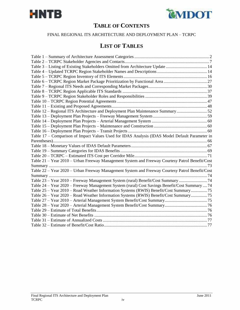
TABLE OF CONTENTS
FINAL REGIONAL ITS ARCHITECTURE AND DEPLOYMENT PLAN – TCRPC
Final Regional ITS Architecture and Deployment Plan June 2011
TCRPC iv
LIST OF TABLES
Table 1 – Summary of Architecture Assessment Categories ..................................................................... 2 Table 2 – TCRPC Stakeholder Agencies and Contacts .............................................................................. 7 Table 3 – Listing of Existing Stakeholders Omitted from Architecture Update ...................................... 14 Table 4 – Updated TCRPC Region Stakeholder Names and Descriptions .............................................. 14 Table 5 – TCRPC Region Inventory of ITS Elements ............................................................................. 16 Table 6 – TCRPC Region Market Package Prioritization by Functional Area ........................................ 27 Table 7 – Regional ITS Needs and Corresponding Market Packages ...................................................... 30 Table 8 – TCRPC Region Applicable ITS Standards .............................................................................. 37 Table 9 – TCRPC Region Stakeholder Roles and Responsibilities ......................................................... 39 Table 10 – TCRPC Region Potential Agreements ................................................................................... 47 Table 11 – Existing and Proposed Agreements ........................................................................................ 48 Table 12 – Regional ITS Architecture and Deployment Plan Maintenance Summary ............................ 52 Table 13 – Deployment Plan Projects – Freeway Management System .................................................. 59 Table 14 – Deployment Plan Projects – Arterial Management System ................................................... 60 Table 15 – Deployment Plan Projects – Maintenance and Construction ................................................. 60 Table 16 – Deployment Plan Projects – Transit Projects ......................................................................... 60 Table 17 – Comparison of Impact Values Used for IDAS Analysis (IDAS Model Default Parameter in
Parentheses) .............................................................................................................................................. 66 Table 18 – Monetary Values of IDAS Default Parameters ...................................................................... 67 Table 19 – Summary Categories for IDAS Benefits ................................................................................ 69 Table 20 – TCRPC – Estimated ITS Cost per Corridor Mile ................................................................... 71 Table 21 – Year 2010 – Urban Freeway Management System and Freeway Courtesy Patrol Benefit/Cost
Summary .................................................................................................................................................. 73 Table 22 – Year 2020 – Urban Freeway Management System and Freeway Courtesy Patrol Benefit/Cost
Summary .................................................................................................................................................. 74 Table 23 – Year 2010 – Freeway Management System (rural) Benefit/Cost Summary .......................... 74 Table 24 – Year 2020 – Freeway Management System (rural) Cost Savings Benefit/Cost Summary .... 74 Table 25 – Year 2010 – Road Weather Information Systems (RWIS) Benefit/Cost Summary ............... 75 Table 26 – Year 2020 – Road Weather Information Systems (RWIS) Benefit/Cost Summary ............... 75 Table 27 – Year 2010 – Arterial Management System Benefit/Cost Summary....................................... 75 Table 28 – Year 2020 – Arterial Management System Benefit/Cost Summary....................................... 76 Table 29 – Estimate of Total Benefits ...................................................................................................... 76 Table 30 – Estimate of Net Benefits ........................................................................................................ 76 Table 31 – Estimate of Annualized Costs ................................................................................................ 77 Table 32 – Estimate of Benefit/Cost Ratio ............................................................................................... 77
LIST OF ACRONYMS
Final Regional ITS Architecture and Deployment Plan June 2011
TCRPC v
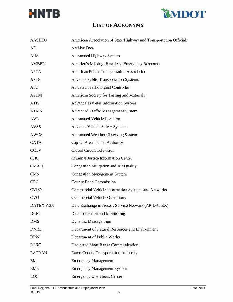
AASHTO American Association of State Highway and Transportation Officials
AD Archive Data
AHS Automated Highway System
AMBER America’s Missing: Broadcast Emergency Response
APTA American Public Transportation Association
APTS Advance Public Transportation Systems
ASC Actuated Traffic Signal Controller
ASTM American Society for Testing and Materials
ATIS Advance Traveler Information System
ATMS Advanced Traffic Management System
AVL Automated Vehicle Location
AVSS Advance Vehicle Safety Systems
AWOS Automated Weather Observing System
CATA Capital Area Transit Authority
CCTV Closed Circuit Television
CJIC Criminal Justice Information Center
CMAQ Congestion Mitigation and Air Quality
CMS Congestion Management System
CRC County Road Commission
CVISN Commercial Vehicle Information Systems and Networks
CVO Commercial Vehicle Operations
DATEX-ASN Data Exchange in Access Service Network (AP-DATEX)
DCM Data Collection and Monitoring
DMS Dynamic Message Sign
DNRE Department of Natural Resources and Environment
DPW Department of Public Works
DSRC Dedicated Short Range Communication
EATRAN Eaton County Transportation Authority
EM Emergency Management
EMS Emergency Management System
EOC Emergency Operations Center
LIST OF ACRONYMS
Final Regional ITS Architecture and Deployment Plan June 2011
TCRPC vi
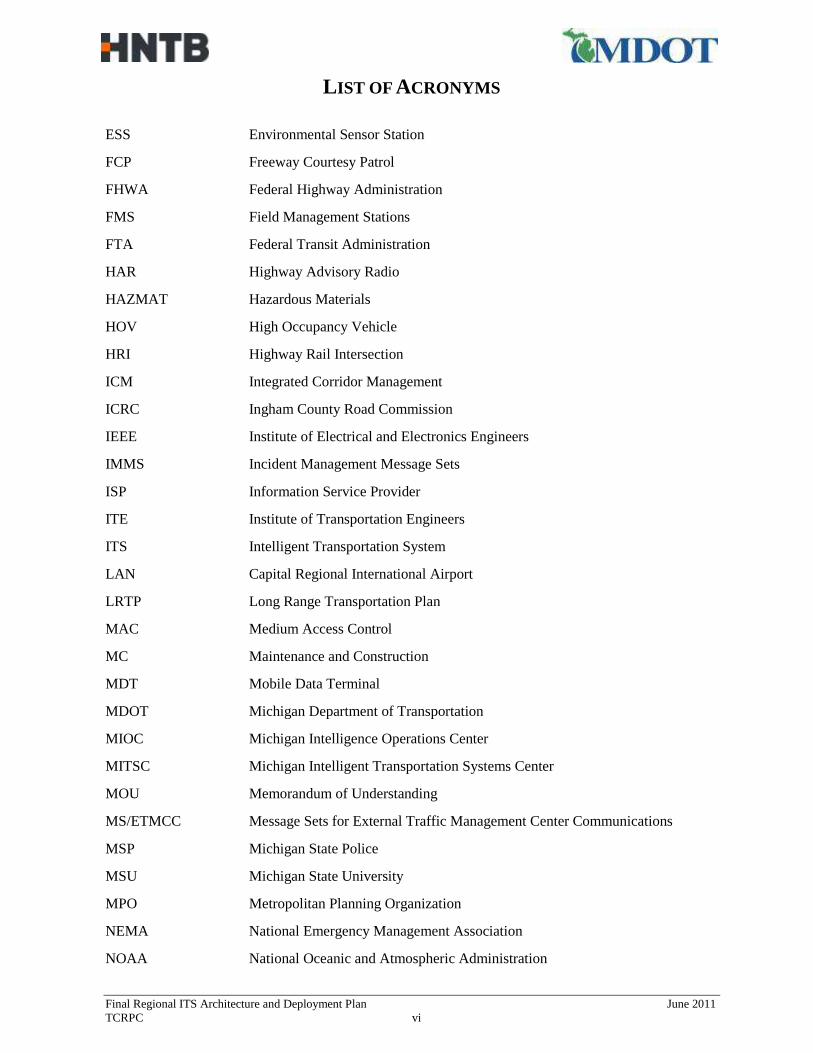
ESS Environmental Sensor Station
FCP Freeway Courtesy Patrol
FHWA Federal Highway Administration
FMS Field Management Stations
FTA Federal Transit Administration
HAR Highway Advisory Radio
HAZMAT Hazardous Materials
HOV High Occupancy Vehicle
HRI Highway Rail Intersection
ICM Integrated Corridor Management
ICRC Ingham County Road Commission
IEEE Institute of Electrical and Electronics Engineers
IMMS Incident Management Message Sets
ISP Information Service Provider
ITE Institute of Transportation Engineers
ITS Intelligent Transportation System
LAN Capital Regional International Airport
LRTP Long Range Transportation Plan
MAC Medium Access Control
MC Maintenance and Construction
MDT Mobile Data Terminal
MDOT Michigan Department of Transportation
MIOC Michigan Intelligence Operations Center
MITSC Michigan Intelligent Transportation Systems Center
MOU Memorandum of Understanding
MS/ETMCC Message Sets for External Traffic Management Center Communications
MSP Michigan State Police
MSU Michigan State University
MPO Metropolitan Planning Organization
NEMA National Emergency Management Association
NOAA National Oceanic and Atmospheric Administration
LIST OF ACRONYMS
Final Regional ITS Architecture and Deployment Plan June 2011
TCRPC vii
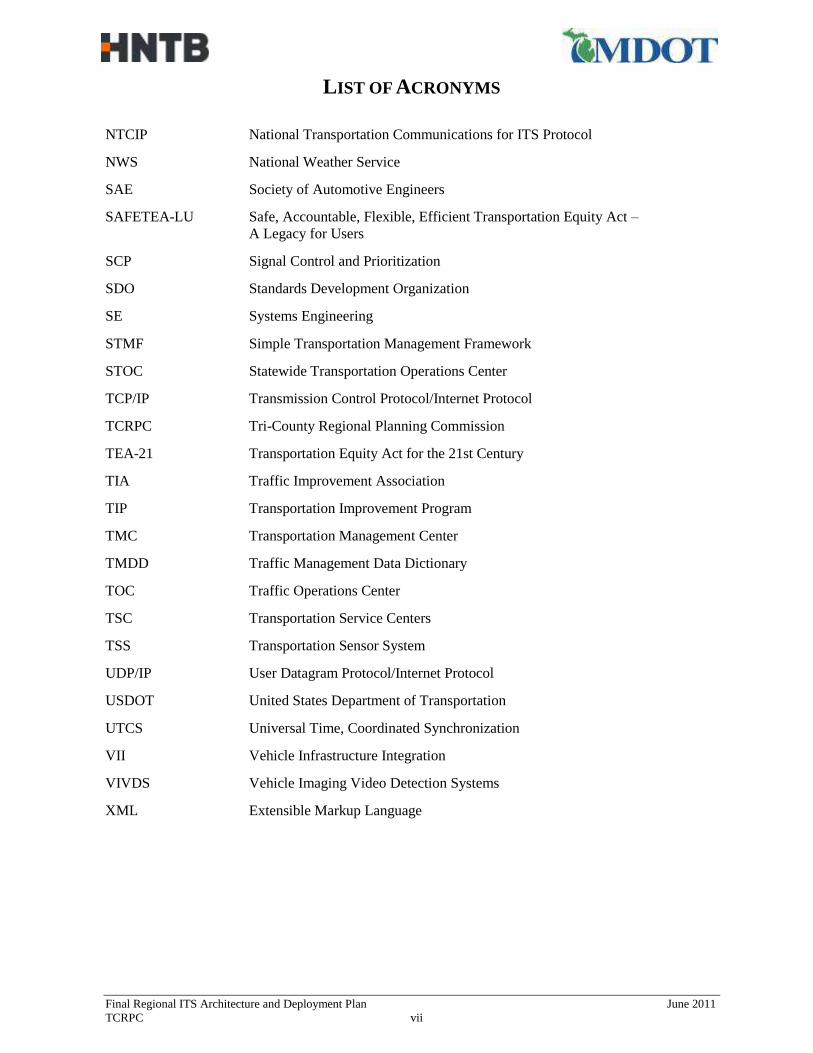
NTCIP National Transportation Communications for ITS Protocol
NWS National Weather Service
SAE Society of Automotive Engineers
SAFETEA-LU Safe, Accountable, Flexible, Efficient Transportation Equity Act –
A Legacy for Users
SCP Signal Control and Prioritization
SDO Standards Development Organization
SE Systems Engineering
STMF Simple Transportation Management Framework
STOC Statewide Transportation Operations Center
TCP/IP Transmission Control Protocol/Internet Protocol
TCRPC Tri-County Regional Planning Commission
TEA-21 Transportation Equity Act for the 21st Century
TIA Traffic Improvement Association
TIP Transportation Improvement Program
TMC Transportation Management Center
TMDD Traffic Management Data Dictionary
TOC Traffic Operations Center
TSC Transportation Service Centers
TSS Transportation Sensor System
UDP/IP User Datagram Protocol/Internet Protocol
USDOT United States Department of Transportation
UTCS Universal Time, Coordinated Synchronization
VII Vehicle Infrastructure Integration
VIVDS Vehicle Imaging Video Detection Systems
XML Extensible Markup Language
Final Regional ITS Architecture and Deployment Plan June 2011
TCRPC 1
1 Introduction
1.1 Project Overview
Development of a regional intelligent transportation system (ITS) architecture is one of the most
important steps in planning for and implementing ITS in a region. ITS architectures provide a
framework for implementing ITS projects, encourage interoperability and resource sharing
among agencies, identify applicable standards to apply to projects, and allow for cohesive long-
range planning among regional stakeholders. The ITS architecture allows stakeholders to plan for
what they want their system to look like in the long-term, and then divide the system into smaller,
more modular pieces that can be implemented over time as funding permits.
ITS architectures satisfy the conformity requirements first established in the Transportation
Equity Act for the 21st Century (TEA-21) highway bill and continued in the Safe, Accountable,
Flexible, Efficient Transportation Equity Act: A Legacy for Users (SAFETEA-LU) bill passed in
2005. In response to Section 5206(e) of TEA-21, the Federal Highway Administration (FHWA)
issued a final rule and the Federal Transit Administration (FTA) issued a final policy that
required regions implementing any ITS projects using federal funds to have an ITS architecture in
place by April 2005. After this date, any ITS project must show conformance with their regional
ITS architecture to be eligible for funding from FHWA or FTA. Regions that had not yet
deployed ITS were given four years to develop an ITS architecture after their first ITS project
proceeded to final design.
In July 2010, the Michigan Department of Transportation (MDOT) began an update of the Tri-
County Regional Planning Commission (TCRPC) Regional ITS Architecture. The regional ITS
architecture has the same geographic boundaries of the TCRPC Region and focuses on a 10- to
15-year vision of ITS for the Region. In addition, a separate ITS Deployment Plan was developed
to identify and prioritize specific ITS projects recommended for the Region in order to implement
the ITS architecture. The update for the TCRPC was completed in tandem with an update for the
Grand Valley Metro Council (GVMC) of Governments. These updates successfully align all of
the ITS architectures and deployment plans into a consistent format for the state of Michigan.
This not only provides a consistent ITS vision for the state, but also provides a consistent
benefit/cost analysis for all ITS projects that can be used for prioritizing projects at the statewide
level.
The update of the regional ITS architecture and the development of the ITS deployment plan
were assembled with significant input from local, state, and federal officials. A series of
workshops have been held to solicit input from stakeholders and ensure that the plans reflect the
unique needs of the Region. This draft report was provided to all stakeholders for comment. The
regional ITS architecture and deployment plan reflects an accurate snapshot of existing ITS
deployments and future ITS plans in the Region. The needs and priorities of the Region will
change over time; to remain effective this plan should be reviewed and updated periodically.
1.2 Document Overview
The TCRPC Regional ITS Architecture report is organized into five key sections:
Section 1 – Introduction
This section provides an overview of the National ITS Architecture requirements, the TCRPC
Regional ITS Architecture, and the key features and stakeholders in the TCRPC Region.
Section 2 – Regional ITS Architecture Development Process
Final Regional ITS Architecture and Deployment Plan June 2011
TCRPC 2
An overview of the key steps involved in updating the regional ITS architecture for the TCRPC
Region is provided in this section. It includes a discussion of stakeholder involvement,
architecture workshops, and the architecture update process.
Section 3 – Customization of the National ITS Architecture for the TCRPC Region
This section contains a summary of regional needs and details the customization of the National
ITS Architecture to meet the ITS vision for the Region. The market packages that were selected
for the Region are included in this section. Additionally, the interconnect diagram, or “sausage
diagram,” is presented to show the relationships of the key subsystems and elements in the
Region.
Section 4 – Application of the Regional ITS Architecture
Functional requirements and standards that apply to the Region, as indicated by the regional ITS
architecture, are presented in Section 4. Operational concepts identifying stakeholder roles and
responsibilities have been prepared and potential agreements to support the data sharing and
resources will be identified. Based on feedback received at the Architecture Workshop, this
section provides some “next step” guidelines for agencies that wish to take a market package
forward and implement a project.
Section 5 – Maintaining the Regional ITS Architecture
A use and maintenance plan was developed for the TCRPC Regional ITS Architecture and is
included in this section. The plan outlines the procedure for updating the regional ITS
architecture over time.
The TCRPC Regional ITS Architecture also contains five appendices.
Appendix A – National ITS Architecture Market Package Definitions
Appendix B – Customized Market Packages
Appendix C – Element Functional Requirements
Appendix D – Stakeholder Database
Appendix E – Architecture Conformance and Maintenance Documentation Form
1.3 Assessment
The TCRPC Regional ITS Architecture and Deployment Plan has been assessed based on twelve
items derived from both the April 8, 2001 USDOT ITS Architecture and Standards Conformity
Rule/Policy and from the architecture development process described in the Regional ITS
Architecture Guidance Document. A listing of these items is shown in Table 1.
Table 1 – Summary of Architecture Assessment Categories
Content Criteria
1. Architecture Scope
2. Stakeholder Identification
3. System Inventory
4. Needs and Services
5. Operational Concept
6. Functional Requirements
7. Interfaces/Flows
Architecture Implementation Criteria
8. Implementation Plan (use)
9. Maintenance Plan
10. Agreements
11. Standards Identification
12. Project Sequencing
Final Regional ITS Architecture and Deployment Plan June 2011
TCRPC 3
1.4 The TCRPC Region
1.4.1 Geographic Overview
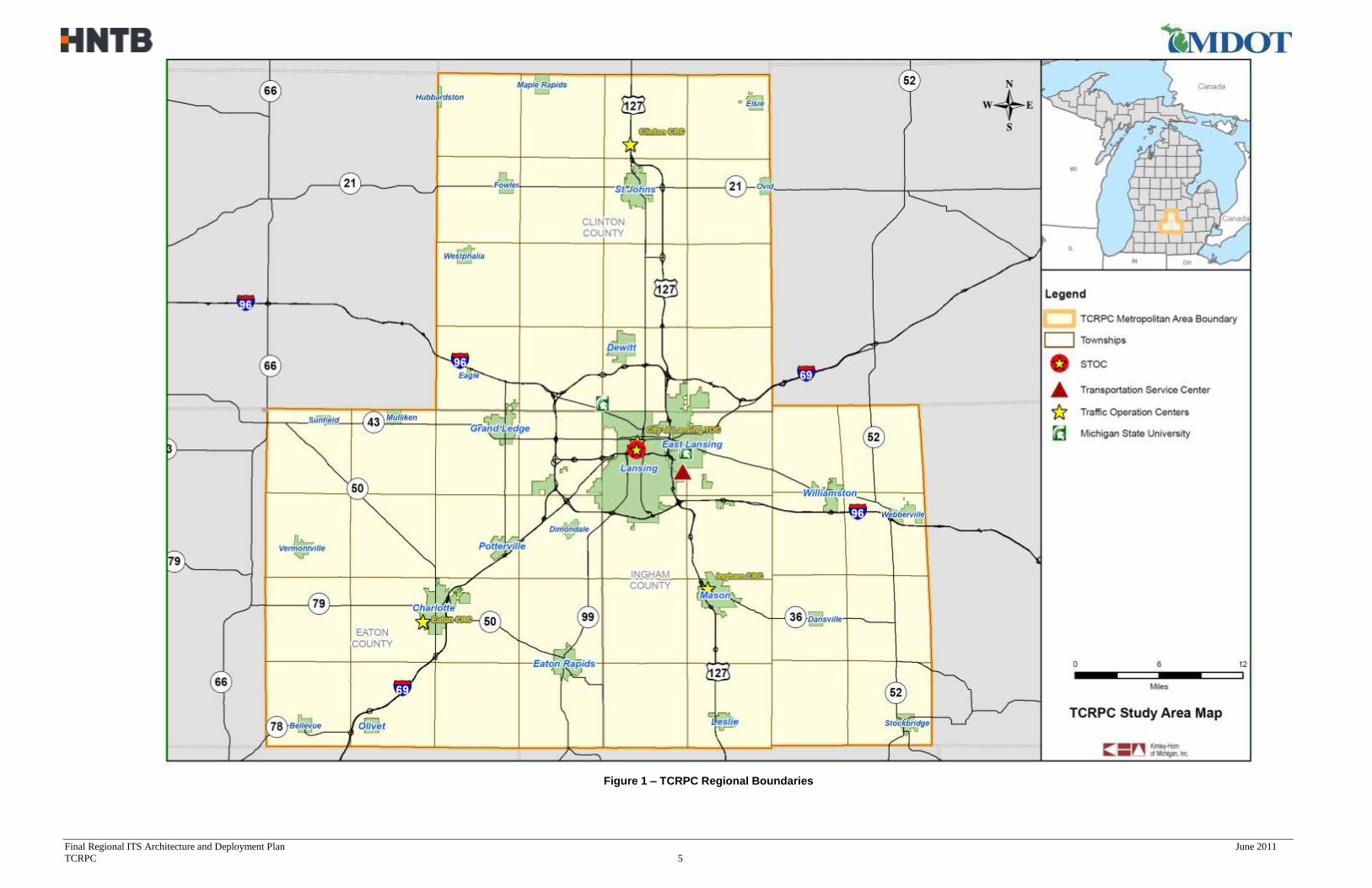
The TCRPC Regional ITS Architecture geographic area is defined by the boundaries of the
TCRPC MPO, which includes Ingham County, Eaton County, and Clinton County. The
largest city within the Region is Lansing, which is the capital of Michigan and has an
estimated 2009 population of 113,810 according to the US Census. Other cities and
townships within the Region include Meridian, Delta, and East Lansing, the home of
Michigan State University. A map of the TCRPC Region is included in Figure 1.
To update the TCRPC Regional ITS Architecture, the project team coordinated with MDOT
and TCRPC to identify and invite the appropriate cities, townships, state and federal
agencies, and transit providers. Stakeholders included representatives from transportation,
transit, and public safety agencies throughout the Region.
As part of the TCRPC Regional ITS Architecture update, a 10- to 15-year vision for ITS in
the Region was documented. In the ITS Deployment Plan, the 10- to 15-year time frame
was divided into smaller time periods to prioritize and sequence the projects. The naming
convention used for elements in the TCRPC Regional ITS Architecture is consistent with
the naming convention that is used in the Grand, SEMCOG, Superior, Bay, North, and
Southwest Regions as well as the Statewide ITS Architecture. This consistency provides
seamless connections to those architectures without requiring that they be specifically
identified. Statewide initiatives, such as statewide commercial vehicle operations and 511
traveler information service, are referenced in the TCRPC Regional ITS Architecture, but
are addressed in further detail in the Statewide ITS Architecture.
1.4.2 Transportation Infrastructure
The TCRPC Region is served by a number of significant federal and state highways,
including I-69, I-96, I-496, and US 127. The I-496 corridor runs straight through the
Lansing metropolitan area providing freeway access from I-69/I-96 into downtown Lansing.
For a portion of the freeway, it runs concurrently with US 127. Based on MDOT average
daily traffic (ADT) counts for 2009, the I-496 corridor through downtown and the I-69/I-96
corridor west of downtown have the heaviest volumes of traffic with some segments of each
corridor experiencing ADTs over 60,000. The US 127/I-496 corridor that runs north and
south through downtown has ADTs over 50,000 as does the I-96 corridor to the east of
Lansing. Other key corridors with high ADTs in the TCRPC Region include Business 69
and M-43, both of which are east-west corridors that travel through Lansing and East
Lansing. There currently are no toll roads or high occupancy vehicle lanes in the Region.
The key corridors through the TCRPC Region for intrastate and interstate travel include
I-69, I-96, and US 127. I-96 is an east-west corridor and serves as the primary route to
connect the Tri-County area with Grand Rapids to the west and with Detroit and Windsor,
Canada to the east. I-69 connects the Tri-County area with Indianapolis to the south and
with Flint and Port Huron at the Canadian border to the northeast. US 127 provides the
primary route for travelers heading north towards the Upper Peninsula.
Transit is provided by several different service providers depending on the county. In
Clinton and Eaton Counties, demand response curb-to-curb public transportation is
available. Clinton Transit is the provider in Clinton County and EATRAN is the provider in
Eaton County and Delta and Bath Townships. EATRAN also provides a connector bus
service from Eaton County to downtown Lansing that operates during the morning and
afternoon commute period.
Final Regional ITS Architecture and Deployment Plan June 2011
TCRPC 4
The Capital Area Transportation Authority (CATA) provides service in Clinton, Eaton, and
Ingham Counties. CATA offers fixed-route, demand response, and paratransit service as
well as a rural service that operates in outlying areas of Ingham County. CATA’s fixed-
route service includes limited express services into Lansing and multiple routes serving
Michigan State University in East Lansing. Cities and townships serviced by CATA’s fixed
routes include Lansing, East Lansing, Delhi, Meridian, Williamston, Webberville, Mason,
and Dansville. CATA also provides car and vanpooling matching programs.
Final Regional ITS Architecture and Deployment Plan June 2011
TCRPC 5
Figure 1 – TCRPC Regional Boundaries
Final Regional ITS Architecture and Deployment Plan June 2011
TCRPC 6
1.4.3 TCRPC Regional ITS Plans
The MDOT partnered with TCRPC and other regional stakeholders to initiate the update of
the existing TCRPC Regional ITS Architecture in 2010. The TCRPC Regional ITS
Architecture provides a vision for deployment and operations of ITS and establishes how
future systems in the Region will be integrated. Version 6.1 of the National ITS
Architecture and Version 5.0 of Turbo Architecture were used to complete the regional ITS
architecture updates.
Since the first regional ITS architecture was completed in 2001, the TCRPC has moved
forward with several local and regional ITS programs and deployments. These have come
from a number of different agencies and cover multiple system types such as freeways,
arterial streets, transit, and public safety. A brief summary highlighting some of the ITS
programs and deployments in the TCRPC Region is provided below.
MDOT Statewide Transportation Operations Center (STOC) – MDOT is
completing the first step of the construction of the STOC, located in downtown
Lansing. The STOC will serve as the center of operations for MDOT staff to
monitor and operate the CCTV cameras, DMS, variable speed limit signs, and
vehicle detectors from a statewide perspective. This includes the primary operations
of devices not located within the jurisdictions of the MDOT West Michigan
Transportation Operations Center (WMTOC) in Grand Rapids or MDOT Michigan
Intelligent Transportation Service Center (MITSC), in Detroit. It also will serve as a
back-up for these facilities and provide interregional coordination for incidents with
multi-regional impacts.
Ingham County 911 Joint Dispatch Center – East Lansing and the City of
Lansing have agreed to combine services for the new joint dispatch center in
Ingham County. The new center will combine East Lansing, Meridian, and Ingham
County dispatch centers with the City of Lansing and will handle calls throughout
the county. Additionally, the facility will receive calls for Michigan State
University (MSU). Construction is scheduled to begin in 2011.
City of Lansing TOC – The City of Lansing is completing a new center to serve as
the Traffic Operations Center for the City. It currently is in the planning and design
phase.
MDOT Device Implementation – MDOT is in the process of implementing
several devices, including dynamic message signs (DMS) and closed-circuit
television (CCTV) cameras, along US 127 and I-96 east of Lansing. The devices
will be controlled by the STOC.
AVL for Demand Response Operations – CATA, EATRAN, and Clinton Transit
either have technology integrated on their vehicles or will have it on their vehicles
in the near future. CATA and Clinton Transit currently are in the process of
installing AVL equipment. EATRAN has established funding to implement it in the
near future.
1.4.4 Stakeholders
Stakeholder involvement is one of the key elements necessary for the successful
development of a regional ITS architecture and deployment plan. The vision for how ITS
will be deployed, integrated, and operated needs to be developed with input from all
stakeholder agencies within the Region in order for the plan to truly reflect regional needs
and priorities. Because ITS incorporates much more than traditional surface transportation
Final Regional ITS Architecture and Deployment Plan June 2011
TCRPC 7
infrastructure, it is important that other transportation system stakeholders are brought into
the regional ITS architecture development process. Stakeholder agencies in the TCRPC
Region include transit and public safety agencies in addition to transportation agencies.
Stakeholders at the local, county, and state levels were invited and encouraged to
participate.
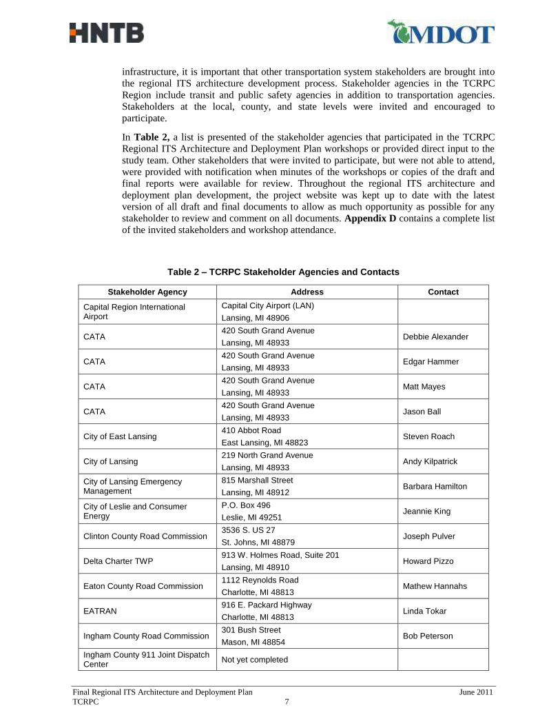
In Table 2, a list is presented of the stakeholder agencies that participated in the TCRPC
Regional ITS Architecture and Deployment Plan workshops or provided direct input to the
study team. Other stakeholders that were invited to participate, but were not able to attend,
were provided with notification when minutes of the workshops or copies of the draft and
final reports were available for review. Throughout the regional ITS architecture and
deployment plan development, the project website was kept up to date with the latest
version of all draft and final documents to allow as much opportunity as possible for any
stakeholder to review and comment on all documents. Appendix D contains a complete list
of the invited stakeholders and workshop attendance.
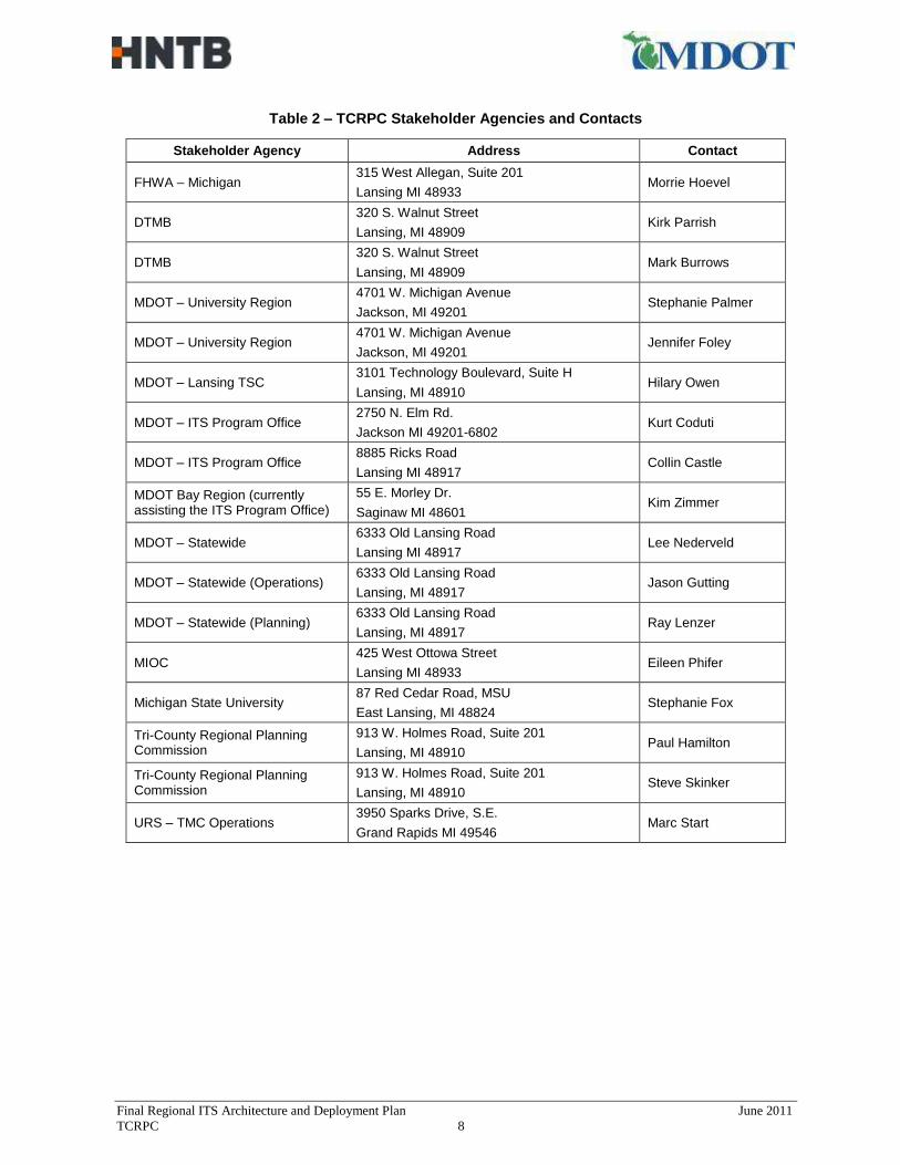
Table 2 – TCRPC Stakeholder Agencies and Contacts
Stakeholder Agency Address Contact
Capital Region International Airport
Capital City Airport (LAN)
Lansing, MI 48906
CATA 420 South Grand Avenue
Lansing, MI 48933 Debbie Alexander
CATA 420 South Grand Avenue
Lansing, MI 48933 Edgar Hammer
CATA 420 South Grand Avenue
Lansing, MI 48933 Matt Mayes
CATA 420 South Grand Avenue
Lansing, MI 48933 Jason Ball
City of East Lansing 410 Abbot Road
East Lansing, MI 48823 Steven Roach
City of Lansing 219 North Grand Avenue
Lansing, MI 48933 Andy Kilpatrick
City of Lansing Emergency Management
815 Marshall Street
Lansing, MI 48912 Barbara Hamilton
City of Leslie and Consumer Energy
P.O. Box 496
Leslie, MI 49251 Jeannie King
Clinton County Road Commission 3536 S. US 27
St. Johns, MI 48879 Joseph Pulver
Delta Charter TWP 913 W. Holmes Road, Suite 201
Lansing, MI 48910 Howard Pizzo
Eaton County Road Commission 1112 Reynolds Road
Charlotte, MI 48813 Mathew Hannahs
EATRAN 916 E. Packard Highway
Charlotte, MI 48813 Linda Tokar
Ingham County Road Commission 301 Bush Street
Mason, MI 48854 Bob Peterson
Ingham County 911 Joint Dispatch Center
Not yet completed
Final Regional ITS Architecture and Deployment Plan June 2011
TCRPC 8
Table 2 – TCRPC Stakeholder Agencies and Contacts
Stakeholder Agency Address Contact
FHWA – Michigan 315 West Allegan, Suite 201
Lansing MI 48933 Morrie Hoevel
DTMB 320 S. Walnut Street
Lansing, MI 48909 Kirk Parrish
DTMB 320 S. Walnut Street
Lansing, MI 48909 Mark Burrows
MDOT – University Region 4701 W. Michigan Avenue
Jackson, MI 49201 Stephanie Palmer
MDOT – University Region 4701 W. Michigan Avenue
Jackson, MI 49201 Jennifer Foley
MDOT – Lansing TSC 3101 Technology Boulevard, Suite H
Lansing, MI 48910 Hilary Owen
MDOT – ITS Program Office 2750 N. Elm Rd.
Jackson MI 49201-6802 Kurt Coduti
MDOT – ITS Program Office 8885 Ricks Road
Lansing MI 48917 Collin Castle
MDOT Bay Region (currently assisting the ITS Program Office)
55 E. Morley Dr.
Saginaw MI 48601 Kim Zimmer
MDOT – Statewide 6333 Old Lansing Road
Lansing MI 48917 Lee Nederveld
MDOT – Statewide (Operations) 6333 Old Lansing Road
Lansing, MI 48917 Jason Gutting
MDOT – Statewide (Planning) 6333 Old Lansing Road
Lansing, MI 48917 Ray Lenzer
MIOC 425 West Ottowa Street
Lansing MI 48933 Eileen Phifer
Michigan State University 87 Red Cedar Road, MSU
East Lansing, MI 48824 Stephanie Fox
Tri-County Regional Planning Commission
913 W. Holmes Road, Suite 201
Lansing, MI 48910 Paul Hamilton
Tri-County Regional Planning Commission
913 W. Holmes Road, Suite 201
Lansing, MI 48910 Steve Skinker
URS – TMC Operations 3950 Sparks Drive, S.E.
Grand Rapids MI 49546 Marc Start
Final Regional ITS Architecture and Deployment Plan June 2011
TCRPC 9
June 2010 August 2010 January 2011 March 2011
2 Regional ITS Architecture Development Process The update of the TCRPC Regional ITS Architecture and Deployment Plan relies heavily on
stakeholder input to ensure that the architecture reflects local needs. A series of two workshops were
held with stakeholders to gather input, and draft documents were made available to stakeholders for
review and comment. The workshops were conducted with stakeholders over nine months and included:
TCRPC Regional ITS Architecture Development Workshop, August 26, 2010; and
TCRPC ITS Deployment Plan Workshop January 18, 2011.
The process followed for the TCRPC Region was designed to ensure that stakeholders could provide
input and review for the update of the Region’s ITS Architecture and development of the Deployment
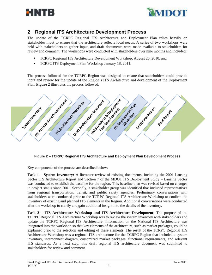
Plan. Figure 2 illustrates the process followed.
Figure 2 – TCRPC Regional ITS Architecture and Deployment Plan Development Process
Key components of the process are described below:
Task 1 – System Inventory: A literature review of existing documents, including the 2001 Lansing
Sector ITS Architecture Report and Section 7 of the MDOT ITS Deployment Study – Lansing Sector
was conducted to establish the baseline for the region. This baseline then was revised based on changes
in project status since 2001. Secondly, a stakeholder group was identified that included representatives
from regional transportation, transit, and public safety agencies. Preliminary conversations with
stakeholders were conducted prior to the TCRPC Regional ITS Architecture Workshop to confirm the
inventory of existing and planned ITS elements in the Region. Additional conversations were conducted
after the workshop to clarify and gain additional insight into the details of the inventory.
Task 2 – ITS Architecture Workshop and ITS Architecture Development: The purpose of the
TCRPC Regional ITS Architecture Workshop was to review the system inventory with stakeholders and
update the TCRPC Regional ITS Architecture. Information on the National ITS Architecture was
integrated into the workshop so that key elements of the architecture, such as market packages, could be
explained prior to the selection and editing of these elements. The result of the TCRPC Regional ITS
Architecture Workshop was a regional ITS architecture for the TCRPC Region that included a system
inventory, interconnect diagram, customized market packages, functional requirements, and relevant
ITS standards. As a next step, this draft regional ITS architecture document was submitted to
stakeholders for review and comment.
Final Regional ITS Architecture and Deployment Plan June 2011
TCRPC 10
Task 3 – ITS Deployment Plan Workshop and ITS Deployment Plan Development: A draft project
listing for the TCRPC Region along with the process taken to develop costs and rankings of the
projected projects was presented to stakeholders at the TCRPC Regional ITS Deployment Plan
Workshop. Additionally, the results from the IDAS analysis were presented for feedback and comment.
Stakeholders were asked to provide input on the recommended projects, responsible agencies,
associated costs, and deployment timeframe. Incorporating feedback from the workshop, the IDAS
results and project priorities were refined and the summarized within the Deployment Plan.
Task 4 – Draft Final and Final Report: Comments received from the Architecture and Deployment
Plan Workshops were integrated into the documents and compiled into the Draft Final report. After a
brief review period, all comments were addressed and the Final Regional ITS Architecture and
Deployment Plan Report was assembled and submitted to the stakeholders.
Final Regional ITS Architecture and Deployment Plan June 2011
TCRPC 11
3 Customization of the National ITS Architecture for the TCRPC Region
3.1 Systems Inventory
An important initial step in the architecture update process is to establish an inventory of existing
ITS elements. Through subsequent discussions with agency representatives, TCRPC Region
stakeholders provided the team with information about existing and planned systems that would
play a role in the Region’s ITS Architecture.
The National ITS Architecture has eight groups of ITS service areas. Existing, planned, and
future systems in the Region were identified in the following service areas:
Traffic Management – example includes the West Michigan Transportation Operations
Center (WMTOC) located in Grand Rapids as well as the Statewide Transportation
Operations Center (STOC) in Lansing, the Michigan Intelligent Transportation System center
(MITSC) in Detroit, and local agency traffic operations centers (TOCs); surveillance
equipment such as detection systems and closed circuit television (CCTV) cameras; fixed and
portable dynamic message signs (DMS), and other related technologies.
Emergency Management – example includes emergency operations/management centers,
improved information sharing among traffic and emergency services, automated vehicle
location (AVL) on emergency vehicles, traffic signal preemption for emergency vehicles, and
wide-area alerts.
Maintenance and Construction Management – example includes work zone management,
roadway maintenance and construction information and environmental sensor stations (ESS).
Public Transportation Management – example includes transit and para-transit AVL, transit
travel information systems, electronic fare collection, and transit security.
Commercial Vehicle Operations – example includes coordination with Commercial Vehicle
Information Systems and Networks (CVISN) efforts, and hazardous material (HAZMAT)
management.
Traveler Information – example includes broadcast traveler information such as MiDrive, or
obtaining information through personal computers.
Archived Data Management – example includes electronic data management and archiving
systems.
Vehicle Safety – example includes collision avoidance and automated highway systems.
3.2 Regional Needs
Needs from the Region were identified by stakeholders at the Regional ITS Architecture
Workshop held in August of 2010. The needs identified provided guidance for determining which
market packages should be included in the architecture. Needs were identified in all service areas
except for vehicle safety.
Section 3.4.3 contains additional information about the specific needs identified and relates those
needs to the market packages that document the corresponding ITS service.
3.3 Element Customization
The inventory and needs documented through the first phase of this process are the starting point.
The identified user services, including ITS systems and the associated components, are used to
Final Regional ITS Architecture and Deployment Plan June 2011
TCRPC 12
customize the National ITS Architecture and update the regional ITS architecture specific to the
TCRPC Region.
When developing customized elements, the stakeholder group agreed not to establish individual
traffic, maintenance, and emergency management elements for individual cities within the
TCRPC Region. City of Lansing, East Lansing, Michigan State University (MSU), and Ingham
County Road Commission (ICRC), were the only local agencies individually identified and
documented. The smaller communities in the Region were documented as part of the local agency
stakeholder names and the elements for those agencies are captured accordingly. For ease in
maintenance of the regional ITS architecture, the stakeholders agreed to this collective grouping
under “Local Agencies”. This documentation allows the communities to be included in the
TCRPC Regional ITS Architecture, and therefore eligible to use federal monies on ITS
deployments. As individual communities or counties deploy user services, the Architecture can be
updated to uniquely capture those agencies and their flows.
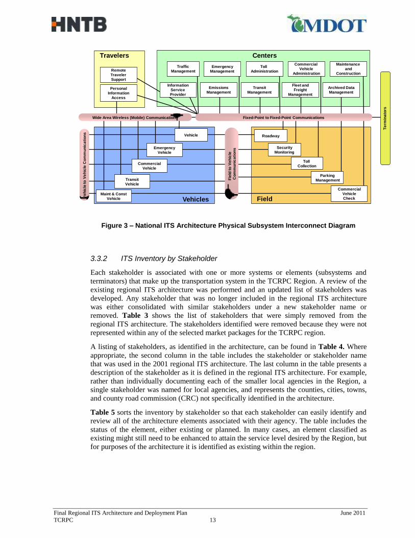
3.3.1 Subsystems and Terminators
Each identified system or component in the TCRPC Regional ITS inventory was mapped to
a subsystem or terminator in the National ITS Architecture. Subsystems and terminators are
the entities that represent systems in ITS. Subsystems are the highest level building blocks
of the physical architecture; the National ITS Architecture groups them into four major
classes: centers, field, vehicles, and travelers. Each of these major classes includes various
components that represent a set of transportation functions (or processes). Each set of
functions is grouped under one agency, jurisdiction, or location, and corresponds to physical
elements such as: traffic operations centers, traffic signals, or vehicles.
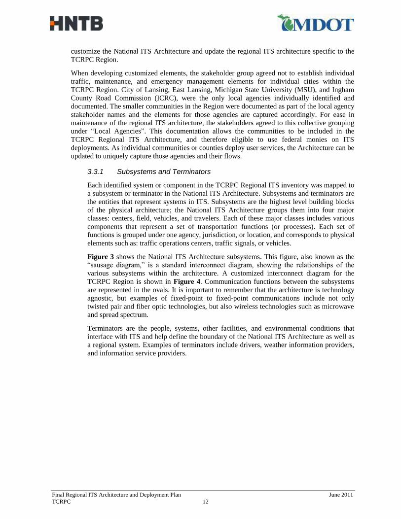
Figure 3 shows the National ITS Architecture subsystems. This figure, also known as the
“sausage diagram,” is a standard interconnect diagram, showing the relationships of the
various subsystems within the architecture. A customized interconnect diagram for the
TCRPC Region is shown in Figure 4. Communication functions between the subsystems
are represented in the ovals. It is important to remember that the architecture is technology
agnostic, but examples of fixed-point to fixed-point communications include not only
twisted pair and fiber optic technologies, but also wireless technologies such as microwave
and spread spectrum.
Terminators are the people, systems, other facilities, and environmental conditions that
interface with ITS and help define the boundary of the National ITS Architecture as well as
a regional system. Examples of terminators include drivers, weather information providers,
and information service providers.
Final Regional ITS Architecture and Deployment Plan June 2011
TCRPC 13
Travelers
Vehicles Field
Centers
Maintenance and
Construction
Archived DataManagement
PersonalInformation
Access
Commercial Vehicle
Administration
Toll Administration
EmergencyManagement
Fleet andFreight
Management
TransitManagement
EmissionsManagement
RemoteTravelerSupport
Wide Area Wireless (Mobile) Communications
InformationServiceProvider
TrafficManagement
CommercialVehicle
EmergencyVehicle
Vehicle
TransitVehicle
Ve
hic
le to
Ve
hic
le C
om
mu
nic
ati
on
s
Maint & ConstVehicle
Fie
ld t
o V
eh
icle
Co
mm
un
ica
tio
ns
Toll Collection
CommercialVehicleCheck
Roadway
ParkingManagement
SecurityMonitoring
Te
rmin
ato
rs
Fixed-Point to Fixed-Point Communications
Figure 3 – National ITS Architecture Physical Subsystem Interconnect Diagram
3.3.2 ITS Inventory by Stakeholder
Each stakeholder is associated with one or more systems or elements (subsystems and
terminators) that make up the transportation system in the TCRPC Region. A review of the
existing regional ITS architecture was performed and an updated list of stakeholders was
developed. Any stakeholder that was no longer included in the regional ITS architecture
was either consolidated with similar stakeholders under a new stakeholder name or
removed. Table 3 shows the list of stakeholders that were simply removed from the
regional ITS architecture. The stakeholders identified were removed because they were not
represented within any of the selected market packages for the TCRPC region.
A listing of stakeholders, as identified in the architecture, can be found in Table 4. Where
appropriate, the second column in the table includes the stakeholder or stakeholder name
that was used in the 2001 regional ITS architecture. The last column in the table presents a
description of the stakeholder as it is defined in the regional ITS architecture. For example,
rather than individually documenting each of the smaller local agencies in the Region, a
single stakeholder was named for local agencies, and represents the counties, cities, towns,
and county road commission (CRC) not specifically identified in the architecture.
Table 5 sorts the inventory by stakeholder so that each stakeholder can easily identify and
review all of the architecture elements associated with their agency. The table includes the
status of the element, either existing or planned. In many cases, an element classified as
existing might still need to be enhanced to attain the service level desired by the Region, but
for purposes of the architecture it is identified as existing within the region.
Final Regional ITS Architecture and Deployment Plan June 2011
TCRPC 14
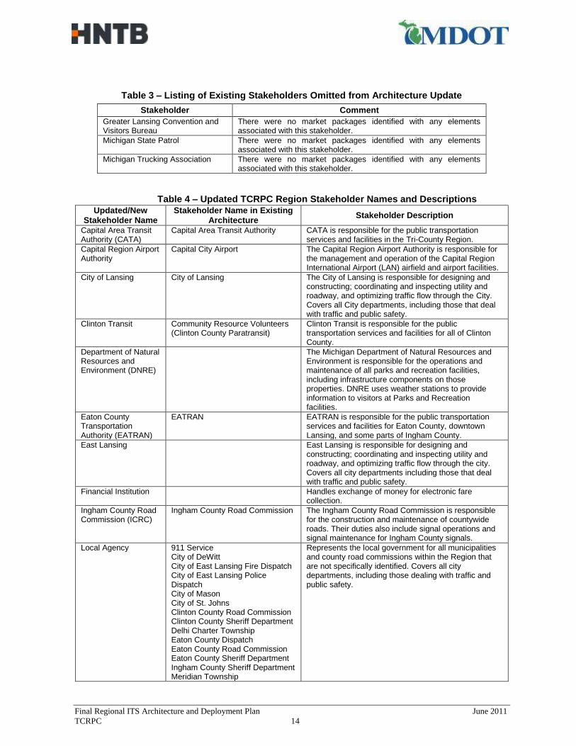
Table 3 – Listing of Existing Stakeholders Omitted from Architecture Update
Stakeholder Comment
Greater Lansing Convention and Visitors Bureau
There were no market packages identified with any elements associated with this stakeholder.
Michigan State Patrol There were no market packages identified with any elements associated with this stakeholder.
Michigan Trucking Association There were no market packages identified with any elements associated with this stakeholder.
Table 4 – Updated TCRPC Region Stakeholder Names and Descriptions
Updated/New Stakeholder Name
Stakeholder Name in Existing Architecture
Stakeholder Description
Capital Area Transit Authority (CATA)
Capital Area Transit Authority CATA is responsible for the public transportation services and facilities in the Tri-County Region.
Capital Region Airport Authority
Capital City Airport The Capital Region Airport Authority is responsible for the management and operation of the Capital Region International Airport (LAN) airfield and airport facilities.
City of Lansing City of Lansing The City of Lansing is responsible for designing and constructing; coordinating and inspecting utility and roadway, and optimizing traffic flow through the City. Covers all City departments, including those that deal with traffic and public safety.
Clinton Transit Community Resource Volunteers (Clinton County Paratransit)
Clinton Transit is responsible for the public transportation services and facilities for all of Clinton County.
Department of Natural Resources and Environment (DNRE)
The Michigan Department of Natural Resources and Environment is responsible for the operations and maintenance of all parks and recreation facilities, including infrastructure components on those properties. DNRE uses weather stations to provide information to visitors at Parks and Recreation facilities.
Eaton County Transportation Authority (EATRAN)
EATRAN EATRAN is responsible for the public transportation services and facilities for Eaton County, downtown Lansing, and some parts of Ingham County.
East Lansing East Lansing is responsible for designing and constructing; coordinating and inspecting utility and roadway, and optimizing traffic flow through the city. Covers all city departments including those that deal with traffic and public safety.
Financial Institution Handles exchange of money for electronic fare collection.
Ingham County Road Commission (ICRC)
Ingham County Road Commission The Ingham County Road Commission is responsible for the construction and maintenance of countywide roads. Their duties also include signal operations and signal maintenance for Ingham County signals.
Local Agency 911 Service City of DeWitt City of East Lansing Fire Dispatch City of East Lansing Police Dispatch City of Mason City of St. Johns Clinton County Road Commission Clinton County Sheriff Department Delhi Charter Township Eaton County Dispatch Eaton County Road Commission Eaton County Sheriff Department Ingham County Sheriff Department Meridian Township
Represents the local government for all municipalities and county road commissions within the Region that are not specifically identified. Covers all city departments, including those dealing with traffic and public safety.
Final Regional ITS Architecture and Deployment Plan June 2011
TCRPC 15
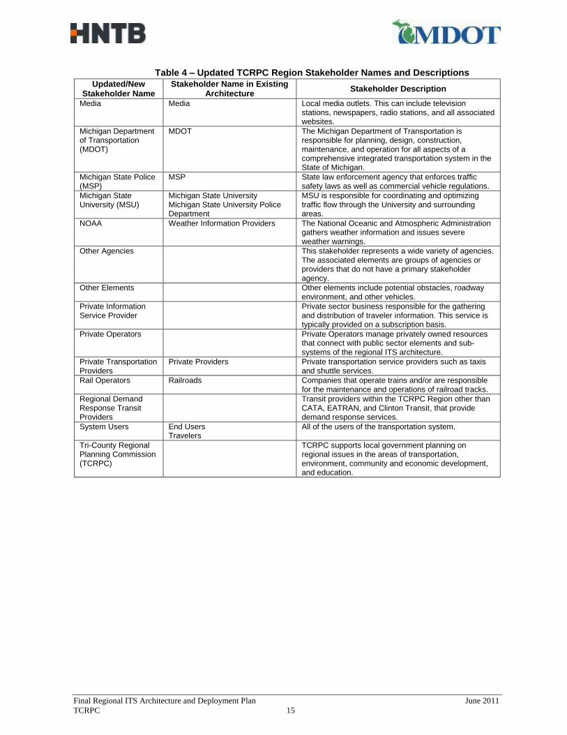
Table 4 – Updated TCRPC Region Stakeholder Names and Descriptions
Updated/New Stakeholder Name
Stakeholder Name in Existing Architecture
Stakeholder Description
Media Media Local media outlets. This can include television stations, newspapers, radio stations, and all associated websites.
Michigan Department of Transportation (MDOT)
MDOT
The Michigan Department of Transportation is responsible for planning, design, construction, maintenance, and operation for all aspects of a comprehensive integrated transportation system in the State of Michigan.
Michigan State Police (MSP)
MSP State law enforcement agency that enforces traffic safety laws as well as commercial vehicle regulations.
Michigan State University (MSU)
Michigan State University Michigan State University Police Department
MSU is responsible for coordinating and optimizing traffic flow through the University and surrounding areas.
NOAA Weather Information Providers The National Oceanic and Atmospheric Administration gathers weather information and issues severe weather warnings.
Other Agencies This stakeholder represents a wide variety of agencies. The associated elements are groups of agencies or providers that do not have a primary stakeholder agency.
Other Elements Other elements include potential obstacles, roadway environment, and other vehicles.
Private Information Service Provider
Private sector business responsible for the gathering and distribution of traveler information. This service is typically provided on a subscription basis.
Private Operators Private Operators manage privately owned resources that connect with public sector elements and sub-systems of the regional ITS architecture.
Private Transportation Providers
Private Providers Private transportation service providers such as taxis and shuttle services.
Rail Operators Railroads Companies that operate trains and/or are responsible for the maintenance and operations of railroad tracks.
Regional Demand Response Transit Providers
Transit providers within the TCRPC Region other than CATA, EATRAN, and Clinton Transit, that provide demand response services.
System Users End Users Travelers
All of the users of the transportation system.
Tri-County Regional Planning Commission (TCRPC)
TCRPC supports local government planning on regional issues in the areas of transportation, environment, community and economic development, and education.
Final Regional ITS Architecture and Deployment Plan June 2011
TCRPC 16
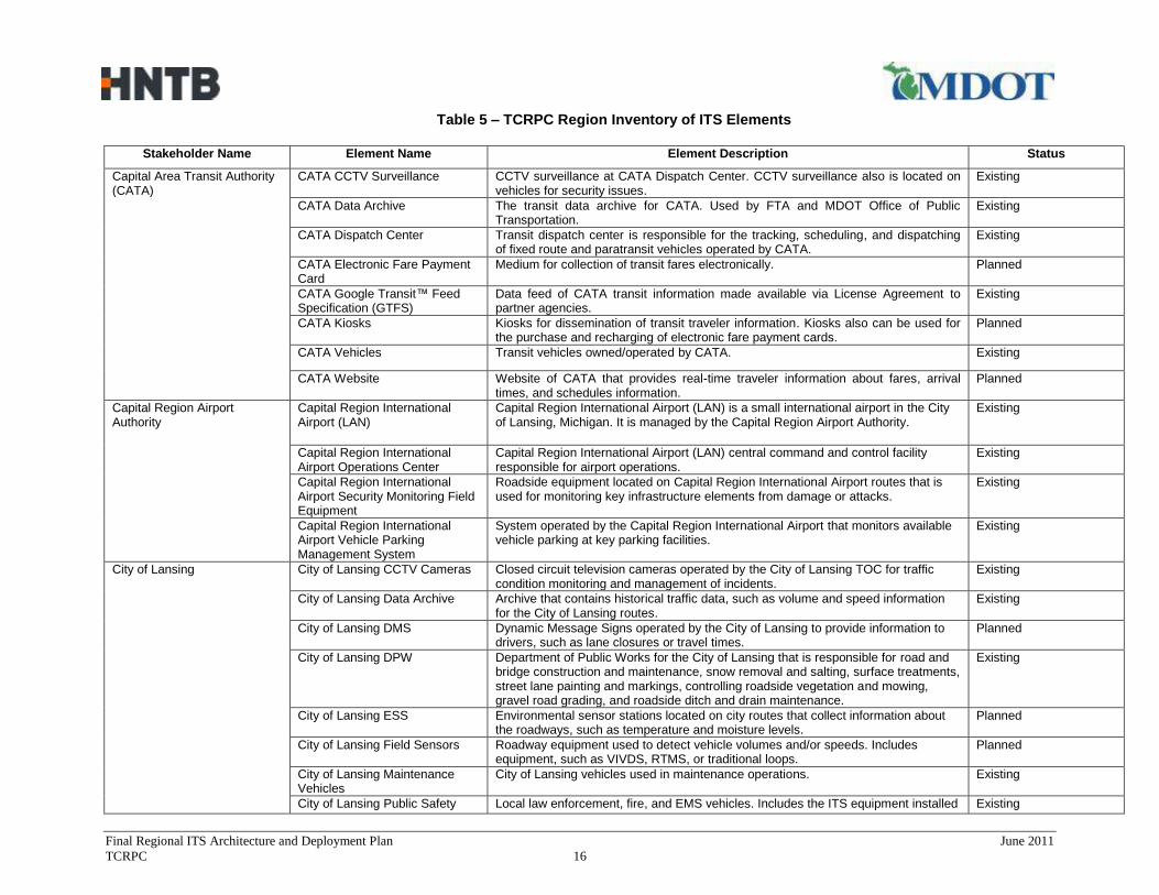
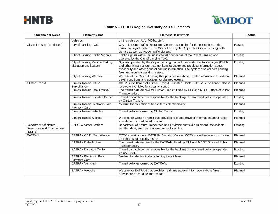
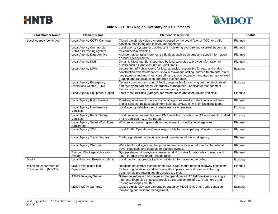
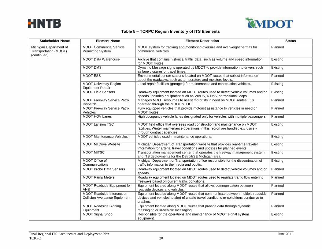
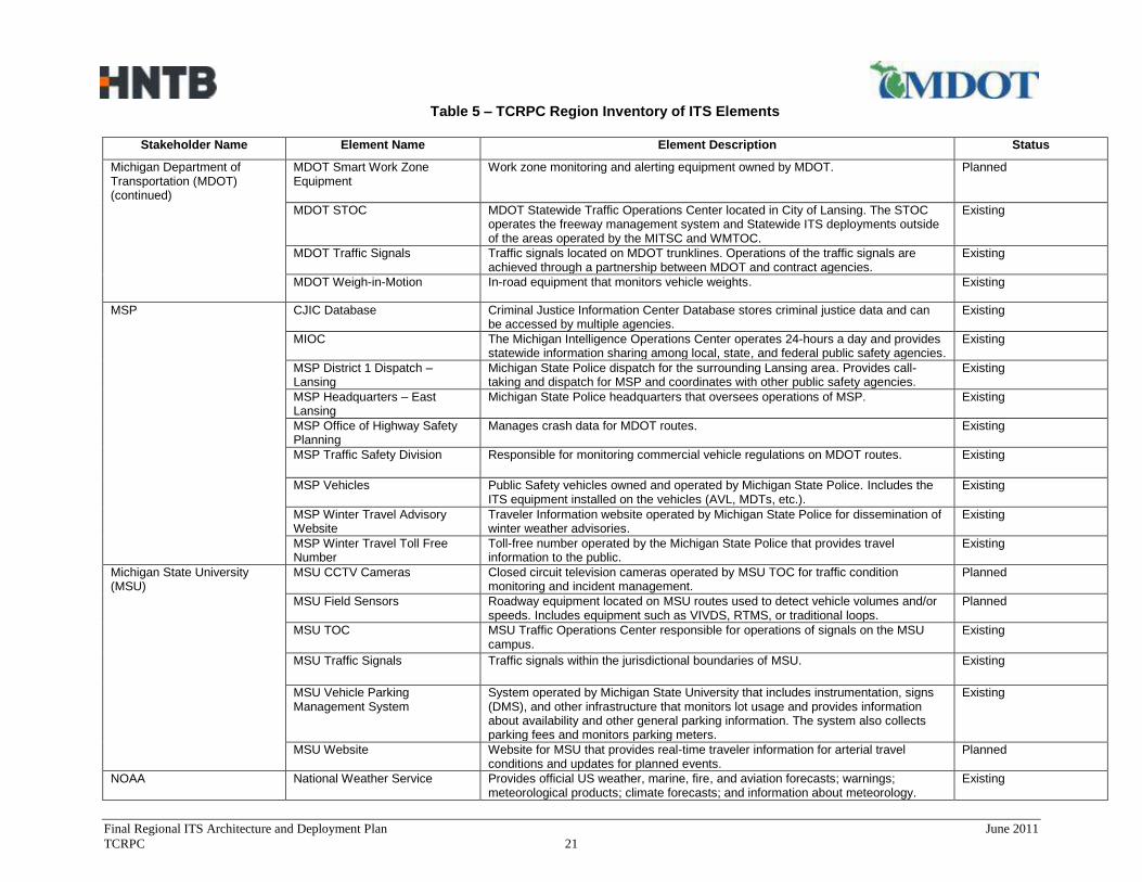
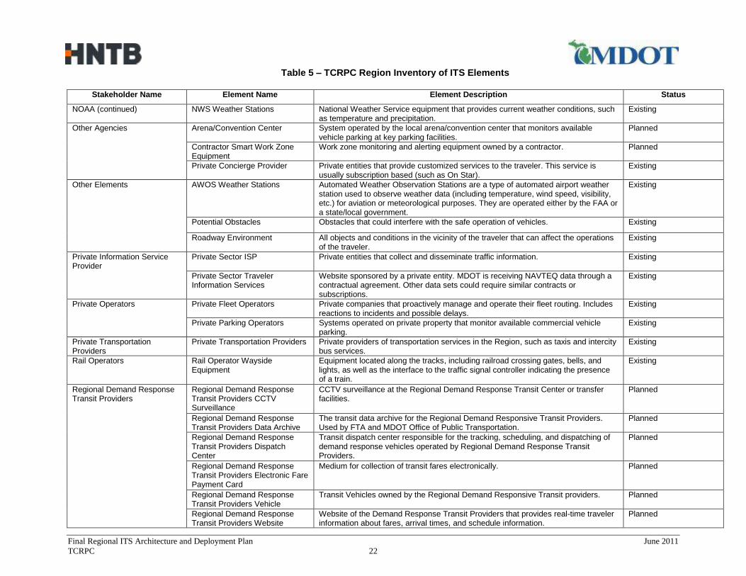
Table 5 – TCRPC Region Inventory of ITS Elements
Stakeholder Name Element Name Element Description Status
Capital Area Transit Authority (CATA)
CATA CCTV Surveillance CCTV surveillance at CATA Dispatch Center. CCTV surveillance also is located on vehicles for security issues.
Existing
CATA Data Archive The transit data archive for CATA. Used by FTA and MDOT Office of Public Transportation.
Existing
CATA Dispatch Center Transit dispatch center is responsible for the tracking, scheduling, and dispatching of fixed route and paratransit vehicles operated by CATA.
Existing
CATA Electronic Fare Payment Card
Medium for collection of transit fares electronically. Planned
CATA Google Transit™ Feed Specification (GTFS)
Data feed of CATA transit information made available via License Agreement to partner agencies.
Existing
CATA Kiosks Kiosks for dissemination of transit traveler information. Kiosks also can be used for the purchase and recharging of electronic fare payment cards.
Planned
CATA Vehicles Transit vehicles owned/operated by CATA. Existing
CATA Website Website of CATA that provides real-time traveler information about fares, arrival times, and schedules information.
Planned
Capital Region Airport Authority
Capital Region International Airport (LAN)
Capital Region International Airport (LAN) is a small international airport in the City of Lansing, Michigan. It is managed by the Capital Region Airport Authority.
Existing
Capital Region International Airport Operations Center
Capital Region International Airport (LAN) central command and control facility responsible for airport operations.
Existing
Capital Region International Airport Security Monitoring Field Equipment
Roadside equipment located on Capital Region International Airport routes that is used for monitoring key infrastructure elements from damage or attacks.
Existing
Capital Region International Airport Vehicle Parking Management System
System operated by the Capital Region International Airport that monitors available vehicle parking at key parking facilities.
Existing
City of Lansing City of Lansing CCTV Cameras Closed circuit television cameras operated by the City of Lansing TOC for traffic condition monitoring and management of incidents.
Existing
City of Lansing Data Archive Archive that contains historical traffic data, such as volume and speed information
for the City of Lansing routes. Existing
City of Lansing DMS Dynamic Message Signs operated by the City of Lansing to provide information to
drivers, such as lane closures or travel times. Planned
City of Lansing DPW Department of Public Works for the City of Lansing that is responsible for road and bridge construction and maintenance, snow removal and salting, surface treatments, street lane painting and markings, controlling roadside vegetation and mowing, gravel road grading, and roadside ditch and drain maintenance.
Existing
City of Lansing ESS Environmental sensor stations located on city routes that collect information about
the roadways, such as temperature and moisture levels. Planned
City of Lansing Field Sensors Roadway equipment used to detect vehicle volumes and/or speeds. Includes
equipment, such as VIVDS, RTMS, or traditional loops. Planned
City of Lansing Maintenance Vehicles
City of Lansing vehicles used in maintenance operations. Existing
City of Lansing Public Safety Local law enforcement, fire, and EMS vehicles. Includes the ITS equipment installed Existing
Final Regional ITS Architecture and Deployment Plan June 2011
TCRPC 17
Table 5 – TCRPC Region Inventory of ITS Elements
Stakeholder Name Element Name Element Description Status
Vehicles on the vehicles (AVL, MDTs, etc.).
City of Lansing (continued) City of Lansing TOC City of Lansing Traffic Operations Center responsible for the operations of the municipal signal system. The City of Lansing TOC operates City of Lansing traffic signals as well as MDOT traffic signals.
Existing
City of Lansing Traffic Signals Traffic signals within the jurisdictional boundaries of the City of Lansing and
operated by the City of Lansing TOC. Existing
City of Lansing Vehicle Parking Management System
System operated by the City of Lansing that includes instrumentation, signs (DMS), and other infrastructure that monitors lot usage and provides information about availability and other general parking information. The system also collects parking fees and monitors parking meters.
Existing
City of Lansing Website Website of the City of Lansing that provides real-time traveler information for arterial
travel conditions and updates for planned events. Planned
Clinton Transit Clinton Transit CCTV Surveillance
CCTV surveillance at Clinton Transit Dispatch Center. CCTV surveillance also is located on vehicles for security issues.
Planned
Clinton Transit Data Archive The transit data archive for Clinton Transit. Used by FTA and MDOT Office of Public Transportation.
Planned
Clinton Transit Dispatch Center Transit dispatch center responsible for the tracking of paratransit vehicles operated by Clinton Transit.
Existing
Clinton Transit Electronic Fare Payment Card
Medium for collection of transit fares electronically. Planned
Clinton Transit Vehicles Transit vehicles owned by Clinton Transit. Existing
Clinton Transit Website Website for Clinton Transit that provides real-time traveler information about fares, arrivals, and schedule information.
Planned
Department of Natural Resources and Environment (DNRE)
DNRE Weather Stations Department of Natural Resources and Environment field equipment that collects weather data, such as temperature and visibility.
Existing
EATRAN EATRAN CCTV Surveillance CCTV surveillance at EATRAN Dispatch Center. CCTV surveillance also is located on vehicles for security issues.
Planned
EATRAN Data Archive The transit data archive for the EATRAN. Used by FTA and MDOT Office of Public Transportation.
Planned
EATRAN Dispatch Center Transit dispatch center responsible for the tracking of paratransit vehicles operated by EATRAN.
Existing
EATRAN Electronic Fare Payment Card
Medium for electronically collecting transit fares. Planned
EATRAN Vehicles Transit vehicles owned by EATRAN. Existing
EATRAN Website Website for EATRAN that provides real-time traveler information about fares, arrivals, and schedule information.
Planned

Final Regional ITS Architecture and Deployment Plan June 2011
TCRPC 18
Table 5 – TCRPC Region Inventory of ITS Elements
Stakeholder Name Element Name Element Description Status
East Lansing East Lansing Data Archive Archive that contains historical traffic data, such as volume and speed information for the East Lansing routes.
Planned
East Lansing TOC The City of East Lansing Traffic Operations Center responsible for the operating the municipal signal system. The East Lansing TOC operates East Lansing traffic signals only.
Existing
East Lansing Traffic Signals Traffic signals within the jurisdictional boundaries of East Lansing and operated by the East Lansing TOC.
Existing
East Lansing Vehicle Parking Management System
System operated by East Lansing that includes instrumentation, signs (DMS), and other infrastructure that monitors lot usage and provides information about availability and other general parking information. The system also collects parking fees and monitors parking meters.
Existing
Financial Institution Financial Service Provider Handles exchange of money for electronic fare collection. Existing
Service Agency Agency responsible for payment of transit fares for medical transportation as part of
government subsidized medical care. This includes Medicare and VA programs. Existing
Ingham County Road Commission (ICRC)
ICRC Traffic Signals Traffic signals within the jurisdictional boundaries of the Ingham County Road Commission and operated by the ICRC TOC.
Existing
ICRC TOC Ingham County Road Commission Traffic Operations Center responsible for the operations of the municipal signal system.
Existing
Local Agency County CCTV Cameras Closed circuit television cameras operated by County TOC for traffic condition monitoring and incident management.
Planned
County Commercial Vehicle Permitting System
County system for tracking and monitoring oversize and overweight permits for commercial vehicles.
Planned
County Data Archive Archive that contains historical traffic data, such as volume and speed information for County Road Commission routes.
Planned
County Road Commission Duties include road and bridge construction and maintenance, snow removal and salting, surface treatments, street lane painting and markings, controlling roadside vegetation and mowing, gravel road grading, and roadside ditch and drain maintenance on County routes. The County Road Commission can be a contract agency with MDOT responsible for MDOT routes within the County. Includes Clinton, Eaton, and Ingham Counties.
Existing
County Road Commission Maintenance Vehicles
Vehicles operated by the County Road Commission for maintenance operations. Includes Clinton, Eaton, and Ingham Counties.
Existing
County TOC County Road Commission Traffic Operations Center responsible for signal system operations on County routes. Includes Clinton and Eaton Counties only.
Planned
County Traffic Signals Traffic signals within the County jurisdictional boundaries. These signals usually are operated by the County TOC. Includes Clinton and Eaton Counties only.
Planned
County Website Website for County Road Commission that provides real-time traveler information for arterial travel conditions and updates for planned events.
Planned
Ingham County 911 Joint Dispatch Center
Joint facility combining dispatches from East Lansing, Lansing, Meridian, and Ingham County. Answers all 911 calls made within the local area and coordinates with other dispatch facilities. This includes counties and municipalities.
Existing
Local Agency 911 Dispatch Answers all 911 calls made from within the local area and coordinates with other
dispatch facilities. This includes counties and municipalities. Existing
Final Regional ITS Architecture and Deployment Plan June 2011
TCRPC 19
Table 5 – TCRPC Region Inventory of ITS Elements
Stakeholder Name Element Name Element Description Status
Local Agency (continued) Local Agency CCTV Cameras Closed circuit television cameras operated by the Local Agency TOC for traffic condition monitoring and incident management.
Planned
Local Agency Commercial Vehicle Permitting System
Local agency system for tracking and monitoring oversize and overweight permits for commercial vehicles.
Planned
Local Agency Data Archive Archive that contains historical traffic data, such as volume and speed information
on local agency routes. Planned
Local Agency DMS Dynamic Message Signs operated by local agencies to provide information to
drivers such as lane closures or travel times. Planned
Local Agency DPW Department of Public Works for local agencies responsible for road and bridge construction and maintenance, snow removal and salting, surface treatments, street lane painting and markings, controlling roadside vegetation and mowing, gravel road grading, and roadside ditch and drain maintenance.
Existing
Local Agency Emergency Operations Center (EOC)
Central command and control facility responsible for carrying out the principals of emergency preparedness, emergency management, or disaster management functions at a strategic level in an emergency situation.
Existing
Local Agency Equipment Repair Local repair facilities (garages) for maintenance and construction vehicles. Planned
Local Agency Field Sensors Roadway equipment operated by local agencies used to detect vehicle volumes
and/or speeds. Includes equipment such as VIVDS, RTMS, or traditional loops. Planned
Local Agency Maintenance Vehicles
Local agency vehicles used in maintenance operations. Existing
Local Agency Public Safety Vehicles
Local law enforcement, fire, and EMS vehicles. Includes the ITS equipment installed on the vehicles (AVL, MDTs, etc.).
Existing
Local Agency Smart Work Zone Equipment
Work zone monitoring and alerting equipment owned by local agencies. Planned
Local Agency TOC Local Traffic Operations Center responsible for municipal signal system operations. Planned
Local Agency Traffic Signals Traffic signals within the jurisdictional boundaries of the local agency. Planned
Local Agency Website Website of local agencies that provides real-time traveler information for arterial
travel conditions and updates for planned events. Planned
Railroad Blockage Notification System
System shares highway-rail intersection (HRI) status for at-grade crossings with users through traveler information tools.
Planned
Media Local Print and Broadcast Media Local media that provide traffic or incident information to the public. Existing
Michigan Department of Transportation (MDOT)
MDOT Anti-Icing Field Equipment
Roadside equipment located along MDOT routes that monitor roadway conditions for freezing conditions and automatically applies chemical or other anti-icing treatment as predetermined thresholds are met.
Planned
ATMS Gateway Server Statewide software that integrates the operations of ITS field devices via a single interface. Examples of access provide view and control of CCTV cameras and posting messages on DMS.
Existing
MDOT CCTV Cameras Closed circuit television cameras operated by MDOT STOC for traffic condition monitoring and incident management.
Existing
Final Regional ITS Architecture and Deployment Plan June 2011
TCRPC 20
Table 5 – TCRPC Region Inventory of ITS Elements
Stakeholder Name Element Name Element Description Status
Michigan Department of Transportation (MDOT) (continued)
MDOT Commercial Vehicle Permitting System
MDOT system for tracking and monitoring oversize and overweight permits for commercial vehicles.
Planned
MDOT Data Warehouse Archive that contains historical traffic data, such as volume and speed information for MDOT routes.
Existing
MDOT DMS Dynamic Message signs operated by MDOT to provide information to drivers such as lane closures or travel times.
Existing
MDOT ESS Environmental sensor stations located on MDOT routes that collect information about the roadways, such as temperature and moisture levels.
Planned
MDOT University Region Equipment Repair
Local repair facilities (garages) for maintenance and construction vehicles. Existing
MDOT Field Sensors Roadway equipment located on MDOT routes used to detect vehicle volumes and/or speeds. Includes equipment such as VIVDS, RTMS, or traditional loops.
Existing
MDOT Freeway Service Patrol Dispatch
Manages MDOT resources to assist motorists in need on MDOT routes. It is operated through the MDOT STOC.
Planned
MDOT Freeway Service Patrol Vehicles
Fully equipped vehicles that provide motorist assistance to vehicles in need on MDOT routes.
Planned
MDOT HOV Lanes High occupancy vehicle lanes designated only for vehicles with multiple passengers. Planned
MDOT Lansing TSC MDOT field office that oversees road construction and maintenance on MDOT facilities. Winter maintenance operations in this region are handled exclusively through contract agencies.
Existing
MDOT Maintenance Vehicles MDOT vehicles used in maintenance operations. Existing
MDOT MI Drive Website Michigan Department of Transportation website that provides real-time traveler information for arterial travel conditions and updates for planned events.
Existing
MDOT MITSC Transportation management center that operates the freeway management system and ITS deployments for the Detroit/SE Michigan area.
Existing
MDOT Office of Communications
Michigan Department of Transportation office responsible for the dissemination of traffic information to the media and public.
Existing
MDOT Probe Data Sensors Roadway equipment located on MDOT routes used to detect vehicle volumes and/or speeds.
Planned
MDOT Ramp Meters Roadway equipment located on MDOT routes used to regulate traffic flow entering freeways based on current traffic conditions.
Planned
MDOT Roadside Equipment for AHS
Equipment located along MDOT routes that allows communication between roadside devices and vehicles.
Planned
MDOT Roadside Intersection Collision Avoidance Equipment
Equipment located along MDOT routes that communicate between multiple roadside devices and vehicles to alert of unsafe travel conditions or conditions conducive to crashes.
Planned
MDOT Roadside Signing Equipment
Equipment located along MDOT routes that provide data through dynamic messaging or in-vehicle messaging.
Planned
MDOT Signal Shop Responsible for the operations and maintenance of MDOT signal system equipment.
Existing
Final Regional ITS Architecture and Deployment Plan June 2011
TCRPC 21
Table 5 – TCRPC Region Inventory of ITS Elements
Stakeholder Name Element Name Element Description Status
Michigan Department of Transportation (MDOT) (continued)
MDOT Smart Work Zone Equipment
Work zone monitoring and alerting equipment owned by MDOT. Planned
MDOT STOC MDOT Statewide Traffic Operations Center located in City of Lansing. The STOC operates the freeway management system and Statewide ITS deployments outside of the areas operated by the MITSC and WMTOC.
Existing
MDOT Traffic Signals Traffic signals located on MDOT trunklines. Operations of the traffic signals are achieved through a partnership between MDOT and contract agencies.
Existing
MDOT Weigh-in-Motion In-road equipment that monitors vehicle weights. Existing
MSP
CJIC Database Criminal Justice Information Center Database stores criminal justice data and can be accessed by multiple agencies.
Existing
MIOC The Michigan Intelligence Operations Center operates 24-hours a day and provides
statewide information sharing among local, state, and federal public safety agencies. Existing
MSP District 1 Dispatch – Lansing
Michigan State Police dispatch for the surrounding Lansing area. Provides call-taking and dispatch for MSP and coordinates with other public safety agencies.
Existing
MSP Headquarters – East Lansing
Michigan State Police headquarters that oversees operations of MSP. Existing
MSP Office of Highway Safety Planning
Manages crash data for MDOT routes. Existing
MSP Traffic Safety Division Responsible for monitoring commercial vehicle regulations on MDOT routes. Existing
MSP Vehicles Public Safety vehicles owned and operated by Michigan State Police. Includes the
ITS equipment installed on the vehicles (AVL, MDTs, etc.). Existing
MSP Winter Travel Advisory Website
Traveler Information website operated by Michigan State Police for dissemination of winter weather advisories.
Existing
MSP Winter Travel Toll Free Number
Toll-free number operated by the Michigan State Police that provides travel information to the public.
Existing
Michigan State University (MSU)
MSU CCTV Cameras Closed circuit television cameras operated by MSU TOC for traffic condition monitoring and incident management.
Planned
MSU Field Sensors Roadway equipment located on MSU routes used to detect vehicle volumes and/or speeds. Includes equipment such as VIVDS, RTMS, or traditional loops.
Planned
MSU TOC MSU Traffic Operations Center responsible for operations of signals on the MSU campus.
Existing
MSU Traffic Signals Traffic signals within the jurisdictional boundaries of MSU. Existing
MSU Vehicle Parking Management System
System operated by Michigan State University that includes instrumentation, signs (DMS), and other infrastructure that monitors lot usage and provides information about availability and other general parking information. The system also collects parking fees and monitors parking meters.
Existing
MSU Website Website for MSU that provides real-time traveler information for arterial travel
conditions and updates for planned events. Planned
NOAA National Weather Service Provides official US weather, marine, fire, and aviation forecasts; warnings; meteorological products; climate forecasts; and information about meteorology.
Existing
Final Regional ITS Architecture and Deployment Plan June 2011
TCRPC 22
Table 5 – TCRPC Region Inventory of ITS Elements
Stakeholder Name Element Name Element Description Status
NOAA (continued) NWS Weather Stations National Weather Service equipment that provides current weather conditions, such as temperature and precipitation.
Existing
Other Agencies
Arena/Convention Center System operated by the local arena/convention center that monitors available vehicle parking at key parking facilities.
Planned
Contractor Smart Work Zone Equipment
Work zone monitoring and alerting equipment owned by a contractor. Planned
Private Concierge Provider Private entities that provide customized services to the traveler. This service is
usually subscription based (such as On Star). Existing
Other Elements AWOS Weather Stations Automated Weather Observation Stations are a type of automated airport weather station used to observe weather data (including temperature, wind speed, visibility, etc.) for aviation or meteorological purposes. They are operated either by the FAA or a state/local government.
Existing
Potential Obstacles Obstacles that could interfere with the safe operation of vehicles. Existing
Roadway Environment All objects and conditions in the vicinity of the traveler that can affect the operations
of the traveler. Existing
Private Information Service Provider
Private Sector ISP Private entities that collect and disseminate traffic information. Existing
Private Sector Traveler Information Services
Website sponsored by a private entity. MDOT is receiving NAVTEQ data through a contractual agreement. Other data sets could require similar contracts or subscriptions.
Existing
Private Operators Private Fleet Operators Private companies that proactively manage and operate their fleet routing. Includes reactions to incidents and possible delays.
Existing
Private Parking Operators Systems operated on private property that monitor available commercial vehicle
parking. Existing
Private Transportation Providers
Private Transportation Providers Private providers of transportation services in the Region, such as taxis and intercity bus services.
Existing
Rail Operators Rail Operator Wayside Equipment
Equipment located along the tracks, including railroad crossing gates, bells, and lights, as well as the interface to the traffic signal controller indicating the presence of a train.
Existing
Regional Demand Response Transit Providers
Regional Demand Response Transit Providers CCTV Surveillance
CCTV surveillance at the Regional Demand Response Transit Center or transfer facilities.
Planned
Regional Demand Response Transit Providers Data Archive
The transit data archive for the Regional Demand Responsive Transit Providers. Used by FTA and MDOT Office of Public Transportation.
Planned
Regional Demand Response Transit Providers Dispatch Center
Transit dispatch center responsible for the tracking, scheduling, and dispatching of demand response vehicles operated by Regional Demand Response Transit Providers.
Planned
Regional Demand Response Transit Providers Electronic Fare Payment Card
Medium for collection of transit fares electronically. Planned
Regional Demand Response Transit Providers Vehicle
Transit Vehicles owned by the Regional Demand Responsive Transit providers. Planned
Regional Demand Response Transit Providers Website
Website of the Demand Response Transit Providers that provides real-time traveler information about fares, arrival times, and schedule information.
Planned
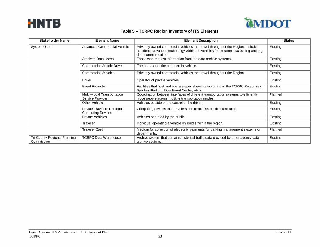
Final Regional ITS Architecture and Deployment Plan June 2011
TCRPC 23
Table 5 – TCRPC Region Inventory of ITS Elements
Stakeholder Name Element Name Element Description Status
System Users Advanced Commercial Vehicle Privately owned commercial vehicles that travel throughout the Region. Include additional advanced technology within the vehicles for electronic screening and tag data communication.
Existing
Archived Data Users Those who request information from the data archive systems. Existing
Commercial Vehicle Driver The operator of the commercial vehicle. Existing
Commercial Vehicles Privately owned commercial vehicles that travel throughout the Region. Existing
Driver Operator of private vehicles. Existing
Event Promoter Facilities that host and operate special events occurring in the TCRPC Region (e.g. Spartan Stadium, Dow Event Center, etc.).
Existing
Multi-Modal Transportation Service Provider
Coordination between interfaces of different transportation systems to efficiently move people across multiple transportation modes.
Planned
Other Vehicle Vehicles outside of the control of the driver. Existing
Private Travelers Personal Computing Devices
Computing devices that travelers use to access public information. Existing
Private Vehicles Vehicles operated by the public. Existing
Traveler Individual operating a vehicle on routes within the region. Existing
Traveler Card Medium for collection of electronic payments for parking management systems or
departments. Planned
Tri-County Regional Planning Commission
TCRPC Data Warehouse Archive system that contains historical traffic data provided by other agency data archive systems.
Existing
Final Regional ITS Architecture and Deployment Plan June 2011
TCRPC 24
3.3.3 Top Level Regional System Interconnect Diagram
A system interconnect diagram, or “sausage diagram” (shown previously in Figure 3),
shows the systems and primary interconnects in the Region. The National ITS Architecture
interconnect diagram has been customized for the TCRPC Region based on the system
inventory and information gathered from the stakeholders.
Figure 4 summarizes the existing and planned ITS elements for the TCRPC Region in the
context of a physical interconnect diagram. Subsystems and elements specific to the Region
are identified in the boxes surrounding the main interconnect diagram; these are color-
coded to the subsystem with which they are associated.
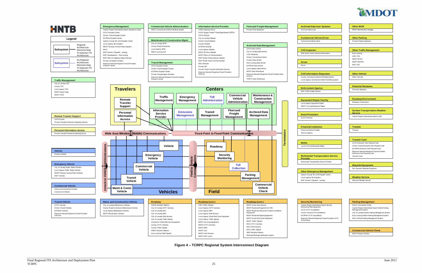
Final Regional ITS Architecture and Deployment Plan June 2011
TCRPC 25
Security Monitoring
Capital Region International Airport Security Monitoring Field Equipment
CATA CCTV Surveillance
Clinton Transit CCTV Surveillance
EATRAN CCTV Surveillance
Regional Demand Response Transit Providers CCTV Surveillance
Traffic Management
City of Lansing TOC
County TOC
Local Agency TOC
MDOT Signal Shop
MDOT STOC
Emergency Management
Capital Region International Airport Operations Center
CATA Dispatch Center
Clinton Transit Dispatch Center
EATRAN Dispatch Center
Ingham County 911 Joint Dispatch Center
Local Agency 911 Dispatch
MDOT Freeway Service Patrol Dispatch
MIOC
MSP District 1 Dispatch - Lansing
MSP Headquarters – East Lansing
MSP Office of Highway Safety Planning
Private Concierge Providers
Regional Demand Response Transit Providers Dispatch Center
Transit Management
CATA Dispatch Center
Clinton Transit Dispatch Center
EATRAN Dispatch Center
Private Transportation Providers
Regional Demand Response Transit Providers Dispatch Center
Maintenance & Construction Mgmt.
City of Lansing DPW
County Road Commission
Local Agency DPW
MDOT Lansing TSC
Information Service Provider
ATMS Gateway Server
CATA Google Transit™ Feed Specification (GTFS)
CATA Website
City of Lansing Website
Clinton Transit Website
County Website
EATRAN Website
Local Agency Website
MDOT MI Drive Website
MDOT Office of Communications
MSP Winter Travel Advisory Website
MSP Winter Travel Toll Free Number
MSU Website
Private ISP
Private Sector Traveler Information Services
Regional Demand Response Transit Providers Website
Archived Data Management
CATA Data Archive
City of Lansing Data Archive
CJIC Database
Clinton Transit Data Archive
County Data Archive
East Lansing Data Archive
EATRAN Data Archive
Local Agency Data Archive
MDOT Data Warehouse
Regional Demand Response Transit Providers Data Archive
TCRPC Data Warehouse
Travelers
Vehicles Field
Centers
Maintenance &ConstructionManagement
Archived DataManagement
PersonalInformation
Access
Commercial Vehicle
Administration
Toll Administration
EmergencyManagement
Fleet andFreight
Management
TransitManagement
EmissionsManagement
RemoteTravelerSupport
Wide Area Wireless (Mobile) Communications
InformationServiceProvider
TrafficManagement
CommercialVehicle
EmergencyVehicle
Vehicle
TransitVehicle
Ve
hic
le to
Ve
hic
le C
om
mu
nic
ati
on
s
Maint & ConstVehicle
Fie
ld t
o V
eh
icle
Co
mm
un
ica
tio
ns
Toll Collection
CommercialVehicleCheck
Roadway
ParkingManagement
SecurityMonitoring
Te
rmin
ato
rs
Fixed-Point to Fixed-Point Communications
Subsystem
Subsystem
Regional
Architecture
Elements Map
To National ITS
Architecture
No Regional
Architecture
Elements Map
To National ITS
Architecture
Legend
Fleet and Freight Management
Private Fleet Operations
Parking Management
Arena / Convention Center
Capital Region International Airport Vehicle Parking Management System
City of Lansing Vehicle Parking Management System
East Lansing Vehicle Parking Management System
MSU Vehicle Parking Management System
Roadway (cont.)
MDOT Probe Data Sensors
MDOT Roadside Equipment for AHS
MDOT Roadside Intersection Collision Avoidance Equipment
MDOT Roadside Signing Equipment
MDOT Smart Work Zone Equipment
MDOT Traffic Signals
MSU CCTV Cameras
MSU Field Sensors
MSU Traffic Signals
NWS Weather Stations
Railroad Blockage Notification System
Commercial Vehicle Check
MDOT Weigh-in-Motion
Commercial Vehicle Administration
MDOT Commercial Vehicle Permitting System
Transit Vehicle
CATA Vehicles
Clinton Transit Vehicles
EATRAN Vehicles
Regional Demand Response Transit Providers Vehicles
Maint. and Construction Vehicle
City of Lansing Maintenance Vehicles
County Road Commission Maintenance Vehicles
Local Agency Maintenance Vehicles
MDOT Maintenance Vehicles
Emergency Vehicle
City of Lansing Public Safety Vehicles
Local Agency Public Safety Vehicles
MDOT Freeway Service Patrol Vehicles
MSP Vehicles
Vehicle
Private Vehicles
Commercial Vehicle
Advanced Commercial Vehicles
Commercial Vehicles
Remote Traveler Support
CATA Kiosks
Private Travelers Personal Computing Devices
Personal Information Access
Private Traveler Personal Computing Device
Archived Data User Systems
Archived Data Users
CVO Information Requestor
County Commercial Vehicle Permitting System
Local Agency Commercial Vehicle Permitting System
Commercial Vehicle Driver
Commercial Vehicle Driver
CVO Inspector
MSP Motor Carrier Division Enforcement
Financial Institution
Financial Service Provider
Service Agency
Event Promoters
Event Promoter
Driver
Driver
Enforcement Agency
MSP Traffic Safety Division
Media
Local Print and Broadcast Media
Other MCM
MDOT Maintenance Garages
Other Traffic Management
East Lansing
ICRC TOC
MDOT MITSC
MDOT WMTOC
MSU TOC
Other Emergency Management
Ingham County 911 Joint Dispatch Center
Local Agency 911 Dispatch
MSP District 1 Dispatch - Lansing
Other Vehicle
Other Vehicles
Other Parking
Private Parking Operators
Traveler Card
CATA Electronic Fare Payment Card
Clinton Transit Electronic Fare Payment Card
EATRAN Electronic Fare Payment Card
Regional Demand Response Transit Providers Electronic Fare Payment Card
Traveler Card
Weather Service
National Weather Service
Potential Obstacles
Potential Obstacles
Roadway Environment
Roadway Environment
Traveler
Traveler
Wayside Equipment
Rail Operator Wayside Equipment
Surface Transportation Weather
Service
Capital Region International Airport (LAN)
Roadway
AWOS Weather Stations
City of Lansing CCTV Cameras
City of Lansing ESS
City of Lansing DMS
City of Lansing Field Sensors
City of Lansing Traffic Signals
Contractor Smart Work Zone Equipment
County CCTV Cameras
County Traffic Signals
DNRE Weather Stations
East Lansing Traffic Signals
Roadway (cont.)
ICRC Traffic Signals
Local Agency CCTV Cameras
Local Agency DMS
Local Agency Field Sensors
Local Agency Smart Work Zone Equipment
Local Agency Traffic Signals
MDOT Anti-Icing Equipment
MDOT CCTV Cameras
MDOT DMS
MDOT ESS
MDOT Field Sensors
MDOT HOV Lanes
Equipment Repair Facility
Local Agency Equipment Repair
MDOT Lansing Equipment Repair
Multimodal Transportation Service
Provider
Multimodal Transportation Service Provider
Figure 4 – TCRPC Regional System Interconnect Diagram
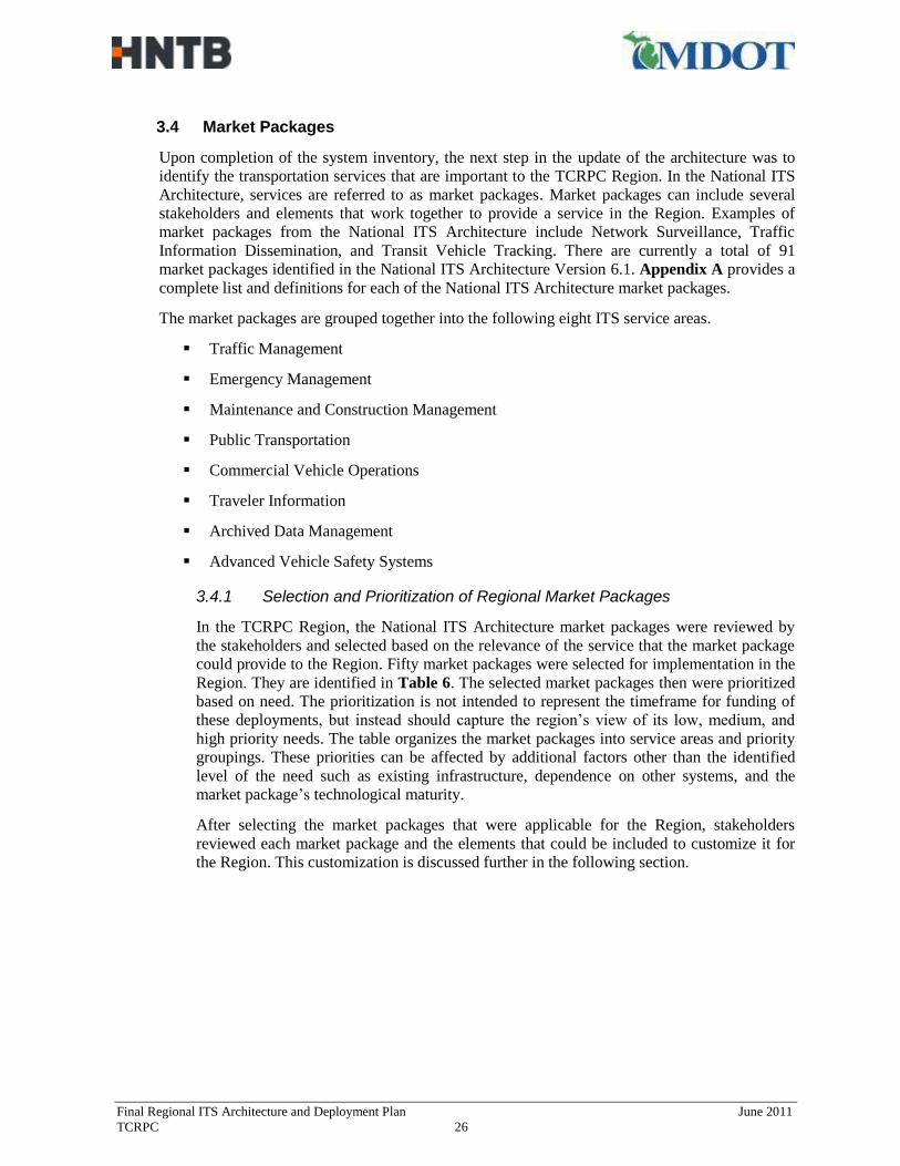
Final Regional ITS Architecture and Deployment Plan June 2011
TCRPC 26
3.4 Market Packages
Upon completion of the system inventory, the next step in the update of the architecture was to
identify the transportation services that are important to the TCRPC Region. In the National ITS
Architecture, services are referred to as market packages. Market packages can include several
stakeholders and elements that work together to provide a service in the Region. Examples of
market packages from the National ITS Architecture include Network Surveillance, Traffic
Information Dissemination, and Transit Vehicle Tracking. There are currently a total of 91
market packages identified in the National ITS Architecture Version 6.1. Appendix A provides a
complete list and definitions for each of the National ITS Architecture market packages.
The market packages are grouped together into the following eight ITS service areas.
Traffic Management
Emergency Management
Maintenance and Construction Management
Public Transportation
Commercial Vehicle Operations
Traveler Information
Archived Data Management
Advanced Vehicle Safety Systems
3.4.1 Selection and Prioritization of Regional Market Packages
In the TCRPC Region, the National ITS Architecture market packages were reviewed by
the stakeholders and selected based on the relevance of the service that the market package
could provide to the Region. Fifty market packages were selected for implementation in the
Region. They are identified in Table 6. The selected market packages then were prioritized
based on need. The prioritization is not intended to represent the timeframe for funding of
these deployments, but instead should capture the region’s view of its low, medium, and
high priority needs. The table organizes the market packages into service areas and priority
groupings. These priorities can be affected by additional factors other than the identified
level of the need such as existing infrastructure, dependence on other systems, and the
market package’s technological maturity.
After selecting the market packages that were applicable for the Region, stakeholders
reviewed each market package and the elements that could be included to customize it for
the Region. This customization is discussed further in the following section.
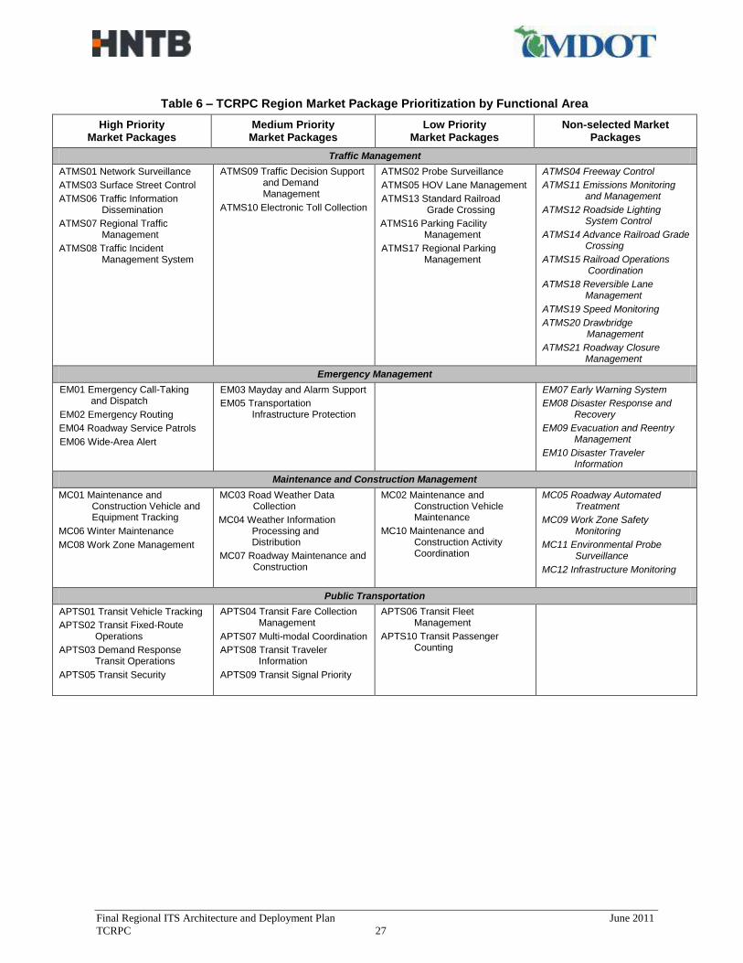
Final Regional ITS Architecture and Deployment Plan June 2011
TCRPC 27
Table 6 – TCRPC Region Market Package Prioritization by Functional Area
High Priority Market Packages
Medium Priority Market Packages
Low Priority Market Packages
Non-selected Market Packages
Traffic Management
ATMS01 Network Surveillance
ATMS03 Surface Street Control
ATMS06 Traffic Information Dissemination
ATMS07 Regional Traffic Management
ATMS08 Traffic Incident Management System
ATMS09 Traffic Decision Support and Demand Management
ATMS10 Electronic Toll Collection
ATMS02 Probe Surveillance
ATMS05 HOV Lane Management
ATMS13 Standard Railroad Grade Crossing
ATMS16 Parking Facility Management
ATMS17 Regional Parking Management
ATMS04 Freeway Control
ATMS11 Emissions Monitoring and Management
ATMS12 Roadside Lighting System Control
ATMS14 Advance Railroad Grade Crossing
ATMS15 Railroad Operations Coordination
ATMS18 Reversible Lane Management
ATMS19 Speed Monitoring
ATMS20 Drawbridge Management
ATMS21 Roadway Closure Management
Emergency Management
EM01 Emergency Call-Taking and Dispatch
EM02 Emergency Routing
EM04 Roadway Service Patrols
EM06 Wide-Area Alert
EM03 Mayday and Alarm Support
EM05 Transportation Infrastructure Protection
EM07 Early Warning System
EM08 Disaster Response and Recovery
EM09 Evacuation and Reentry Management
EM10 Disaster Traveler Information
Maintenance and Construction Management
MC01 Maintenance and Construction Vehicle and Equipment Tracking
MC06 Winter Maintenance
MC08 Work Zone Management
MC03 Road Weather Data Collection
MC04 Weather Information Processing and Distribution
MC07 Roadway Maintenance and Construction
MC02 Maintenance and Construction Vehicle Maintenance
MC10 Maintenance and Construction Activity Coordination
MC05 Roadway Automated Treatment
MC09 Work Zone Safety Monitoring
MC11 Environmental Probe Surveillance
MC12 Infrastructure Monitoring
Public Transportation
APTS01 Transit Vehicle Tracking
APTS02 Transit Fixed-Route Operations
APTS03 Demand Response Transit Operations
APTS05 Transit Security
APTS04 Transit Fare Collection Management
APTS07 Multi-modal Coordination
APTS08 Transit Traveler Information
APTS09 Transit Signal Priority
APTS06 Transit Fleet Management
APTS10 Transit Passenger Counting
Final Regional ITS Architecture and Deployment Plan June 2011
TCRPC 28
Table 6 – TCRPC Region Market Package Prioritization by Functional Area
High Priority Market Packages
Medium Priority Market Packages
Low Priority Market Packages
Non-selected Market Packages
Commercial Vehicle Operations
CVO06 Weigh-in-Motion CVO04 Administrative Processes
CVO10 HAZMAT Management CVO01 Fleet Administration
CVO02 Freight Administration
CVO03 Electronic Clearance
CVO05 International Border Electronic Clearance
CVO07 Roadside CVO Safety
CVO08 On-board CVO and Freight Safety and Security
CVO09 CVO Fleet Maintenance
CVO11 Roadside HAZMAT Security Detection and Mitigation
CVO12 CV Driver Security Authentication
CVO13 Freight Assignment Tracking
Traveler Information
ATIS01 Broadcast Traveler Information
ATIS06 Transportation Operations Data Sharing
ATIS02 Interactive Traveler Information
ATIS05 ISP Based Trip Planning and Route Guidance
ATIS08 Dynamic Ridesharing
ATIS09 In Vehicle Signing
ATIS10 VII Traveler Information
ATSI03 Autonomous Route Guidance
ATIS04 Dynamic Route Guidance
ATIS07 Yellow Pages and Reservations
Archived Data Management
AD1 ITS Data Mart
AD3 ITS Virtual Data Warehouse
AD2 ITS Data Warehouse
Advanced Vehicle Safety Systems
AVSS10 Intersection Collision Avoidance
AVSS11 Automated Highway System
AVSS01 Vehicle Safety Monitoring
AVSS02 Driver Safety Monitoring
AVSS03 Longitudinal Safety Warning
AVSS04 Lateral Safety Warning
AVSS05 Intersection Safety Warning
AVSS06 Pre-Crash Restraint Deployment
AVSS07 Driver Visibility Improvement
AVSS08 Advance Vehicle Longitudinal Control
AVSS09 Advance Vehicle Lateral Control
AVSS12 Cooperative Vehicle Safety Systems
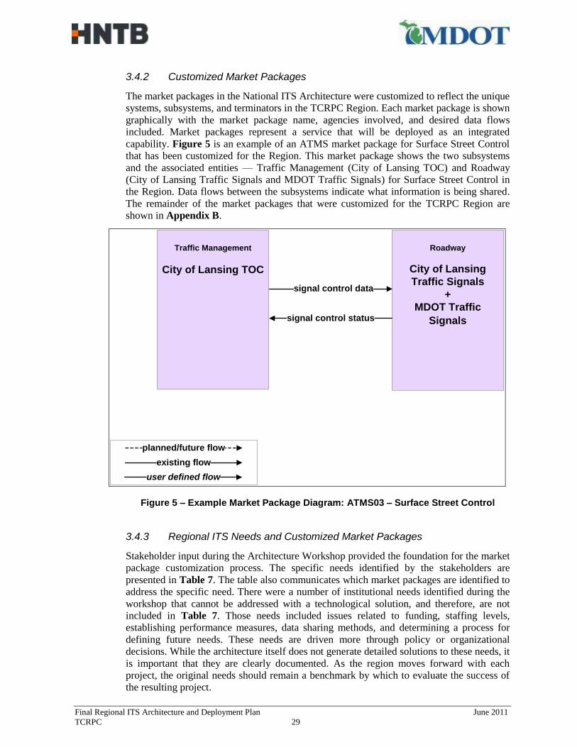
Final Regional ITS Architecture and Deployment Plan June 2011
TCRPC 29
3.4.2 Customized Market Packages
The market packages in the National ITS Architecture were customized to reflect the unique
systems, subsystems, and terminators in the TCRPC Region. Each market package is shown
graphically with the market package name, agencies involved, and desired data flows
included. Market packages represent a service that will be deployed as an integrated
capability. Figure 5 is an example of an ATMS market package for Surface Street Control
that has been customized for the Region. This market package shows the two subsystems
and the associated entities — Traffic Management (City of Lansing TOC) and Roadway
(City of Lansing Traffic Signals and MDOT Traffic Signals) for Surface Street Control in
the Region. Data flows between the subsystems indicate what information is being shared.
The remainder of the market packages that were customized for the TCRPC Region are
shown in Appendix B.
Traffic Management
City of Lansing TOC
Roadway
City of Lansing
Traffic Signals
+
MDOT Traffic
Signals
planned/future flow
existing flow
user defined flow
signal control data
signal control status
Figure 5 – Example Market Package Diagram: ATMS03 – Surface Street Control
3.4.3 Regional ITS Needs and Customized Market Packages
Stakeholder input during the Architecture Workshop provided the foundation for the market
package customization process. The specific needs identified by the stakeholders are
presented in Table 7. The table also communicates which market packages are identified to
address the specific need. There were a number of institutional needs identified during the
workshop that cannot be addressed with a technological solution, and therefore, are not
included in Table 7. Those needs included issues related to funding, staffing levels,
establishing performance measures, data sharing methods, and determining a process for
defining future needs. These needs are driven more through policy or organizational
decisions. While the architecture itself does not generate detailed solutions to these needs, it
is important that they are clearly documented. As the region moves forward with each
project, the original needs should remain a benchmark by which to evaluate the success of
the resulting project.

Final Regional ITS Architecture and Deployment Plan June 2011
TCRPC 30
Table 7 – Regional ITS Needs and Corresponding Market Packages
ITS Need Market Package
Traffic Management
Need improved multi-modal coordination for road network conditions during winter weather conditions and special events (e.g. snow removal plan, MSU football games, etc.)
ATMS07
ATMS08
ATMS16
ATMS17
MC04
MC06
MC10
APTS07
ATIS06
Need real-time data collection ATMS01
ATMS02
ATMS10
MC01
MC03
APT01
APTS10
CVO06
Need to provide real-time back-up when the system fails ATMS07 APTS07
Need to provide wayfinding information (static/dynamic) ATMS06
ATMS08
ATMS16
ATMS17
Public Transportation
Need to integrate fare system with MSU APTS04
Need to incorporate bus priority lanes and/or signal priority APTS02 APTS09
Traveler Information
Need to provide real-time traveler information (transit, traffic, and weather) ATIS01
ATIS02
ATMS06
APTS08
Archive Data Management
Need to provide improved data management AD1 AD3
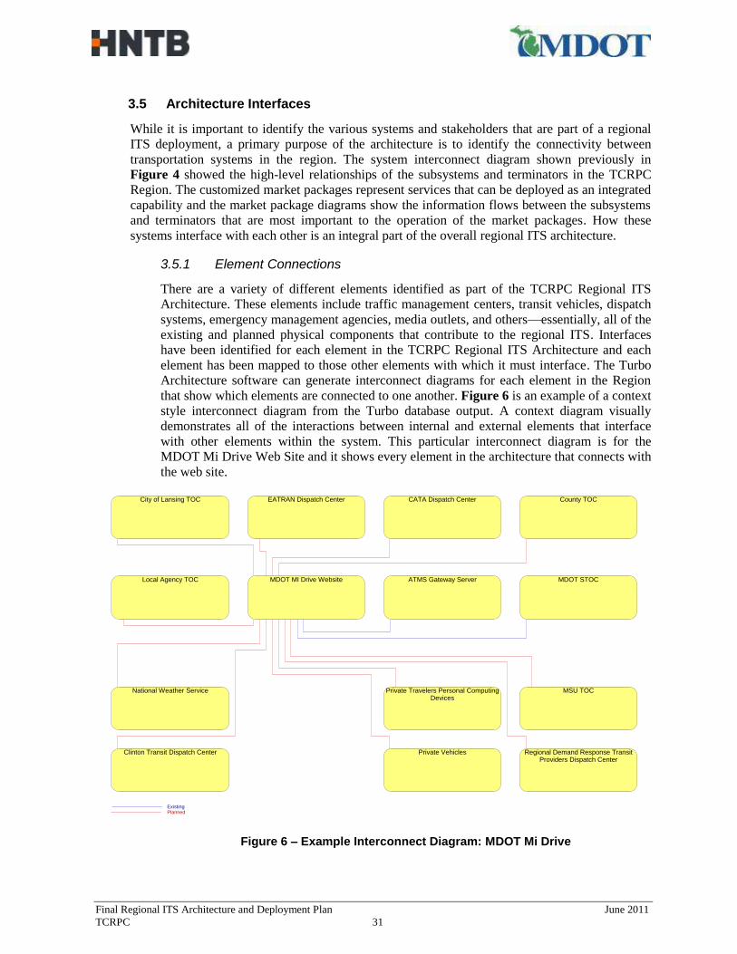
Final Regional ITS Architecture and Deployment Plan June 2011
TCRPC 31
3.5 Architecture Interfaces
While it is important to identify the various systems and stakeholders that are part of a regional
ITS deployment, a primary purpose of the architecture is to identify the connectivity between
transportation systems in the region. The system interconnect diagram shown previously in
Figure 4 showed the high-level relationships of the subsystems and terminators in the TCRPC
Region. The customized market packages represent services that can be deployed as an integrated
capability and the market package diagrams show the information flows between the subsystems
and terminators that are most important to the operation of the market packages. How these
systems interface with each other is an integral part of the overall regional ITS architecture.
3.5.1 Element Connections
There are a variety of different elements identified as part of the TCRPC Regional ITS
Architecture. These elements include traffic management centers, transit vehicles, dispatch
systems, emergency management agencies, media outlets, and others—essentially, all of the
existing and planned physical components that contribute to the regional ITS. Interfaces
have been identified for each element in the TCRPC Regional ITS Architecture and each
element has been mapped to those other elements with which it must interface. The Turbo
Architecture software can generate interconnect diagrams for each element in the Region
that show which elements are connected to one another. Figure 6 is an example of a context
style interconnect diagram from the Turbo database output. A context diagram visually
demonstrates all of the interactions between internal and external elements that interface
with other elements within the system. This particular interconnect diagram is for the
MDOT Mi Drive Web Site and it shows every element in the architecture that connects with
the web site.
MDOT MI Drive Website
City of Lansing TOC EATRAN Dispatch Center CATA Dispatch Center County TOC
Local Agency TOC ATMS Gateway Server MDOT STOC
National Weather Service
Clinton Transit Dispatch Center
MSU TOC
Regional Demand Response TransitProviders Dispatch Center
Private Travelers Personal ComputingDevices
Private Vehicles
ExistingPlanned
Figure 6 – Example Interconnect Diagram: MDOT Mi Drive
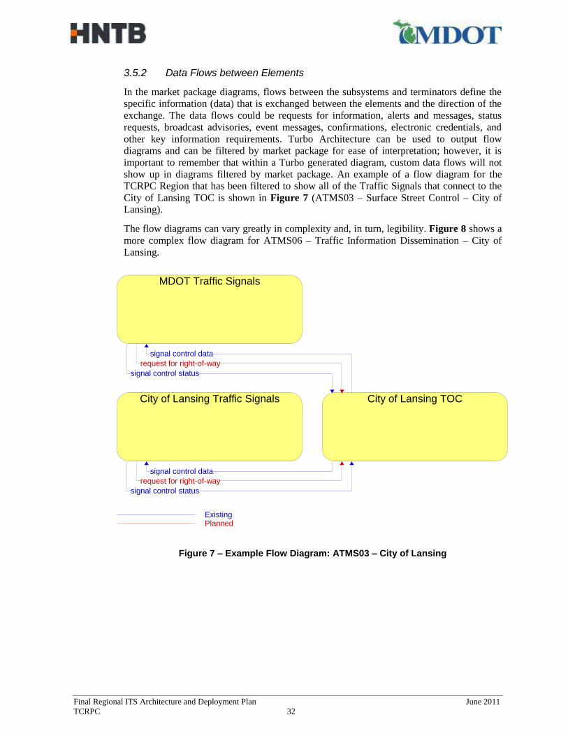
Final Regional ITS Architecture and Deployment Plan June 2011
TCRPC 32
3.5.2 Data Flows between Elements
In the market package diagrams, flows between the subsystems and terminators define the
specific information (data) that is exchanged between the elements and the direction of the
exchange. The data flows could be requests for information, alerts and messages, status
requests, broadcast advisories, event messages, confirmations, electronic credentials, and
other key information requirements. Turbo Architecture can be used to output flow
diagrams and can be filtered by market package for ease of interpretation; however, it is
important to remember that within a Turbo generated diagram, custom data flows will not
show up in diagrams filtered by market package. An example of a flow diagram for the
TCRPC Region that has been filtered to show all of the Traffic Signals that connect to the
City of Lansing TOC is shown in Figure 7 (ATMS03 – Surface Street Control – City of
Lansing).
The flow diagrams can vary greatly in complexity and, in turn, legibility. Figure 8 shows a
more complex flow diagram for ATMS06 – Traffic Information Dissemination – City of
Lansing.
City of Lansing TOC
MDOT Traffic Signals
City of Lansing Traffic Signals
signal control data
request for right-of-way
signal control status
signal control data
request for right-of-way
signal control status
ExistingPlanned
Figure 7 – Example Flow Diagram: ATMS03 – City of Lansing
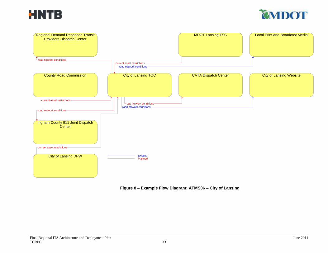
Final Regional ITS Architecture and Deployment Plan June 2011
TCRPC 33
City of Lansing TOC
Regional Demand Response TransitProviders Dispatch Center
MDOT Lansing TSC Local Print and Broadcast Media
County Road Commission CATA Dispatch Center City of Lansing Website
Ingham County 911 Joint DispatchCenter
City of Lansing DPW
road network conditions
current asset restrictions
road network conditions
current asset restrictions
road network conditions
road network conditions
road network conditions
current asset restrictions
ExistingPlanned
Figure 8 – Example Flow Diagram: ATMS06 – City of Lansing

Final Regional ITS Architecture and Deployment Plan June 2011
TCRPC 34
In addition to market package style flow diagrams, Turbo Architecture has the ability to
create flow diagrams that show only the connections between two or three specific elements
or context diagrams that show all of the flows that involve an element. For example, Figure
9 shows a simple flow between two elements, MDOT Mi Drive Website and MDOT STOC.
While this is a portion of the planned interactions, it also could be useful to use a context
diagram for the element, as shown in Figure 10, to view all of the other interactions with
the MDOT STOC so that the project can be designed with the future in mind. However,
context style flow diagrams can get very large and complicated for elements with a larger
number of connections.
MDOT STOC
MDOT MI Drive Website
incident information
road network conditions
ExistingPlanned
Figure 9 – Example Two Element Flow Diagram
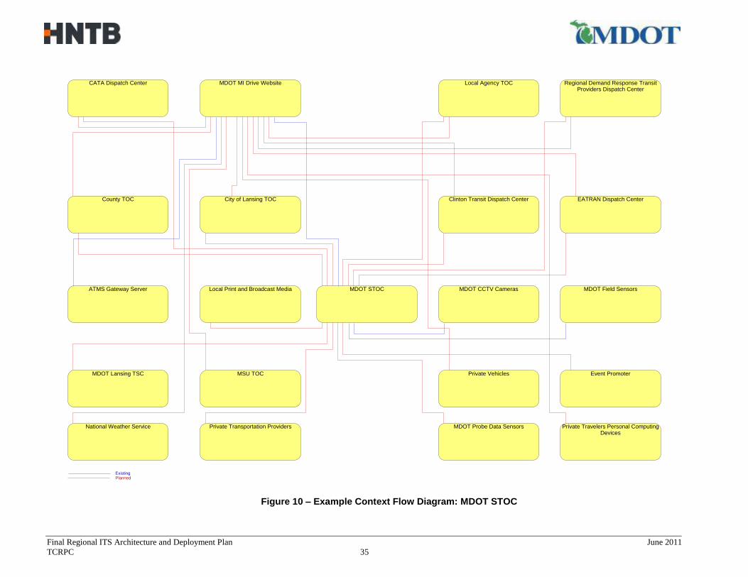
Final Regional ITS Architecture and Deployment Plan June 2011
TCRPC 35
MDOT STOC
MDOT MI Drive Website
City of Lansing TOC
CATA Dispatch Center
County TOC
Local Agency TOC
Clinton Transit Dispatch Center
Regional Demand Response TransitProviders Dispatch Center
EATRAN Dispatch Center
Local Print and Broadcast MediaATMS Gateway Server MDOT CCTV Cameras MDOT Field Sensors
MDOT Lansing TSC
National Weather Service
MSU TOC
Private Transportation Providers
Event Promoter
Private Travelers Personal ComputingDevices
Private Vehicles
MDOT Probe Data Sensors
ExistingPlanned
Figure 10 – Example Context Flow Diagram: MDOT STOC
Final Regional ITS Architecture and Deployment Plan June 2011
TCRPC 36
4 Application of the Regional ITS Architecture Detailed guidance for the stakeholders on the use and maintenance of the regional ITS architecture is
provided in Section 5. This section presents some insight into some of the data that is available to
support implementation of the services identified by the stakeholders. Some of the data that can be
derived from the National ITS Architecture includes recommendations for standards and functional
requirements for ITS elements. In addition, the operational concepts that define the roles and
responsibilities of stakeholders were updated within the regional ITS architecture and document the
stakeholders’ concepts related to the services identified.
It is likely that the implementation of ITS in the TCRPC Region will require interagency agreements.
Potential agreements are identified within this section based on the desired data flows identified in the
regional ITS architecture. Additionally, an integration approach founded within the existing TCRPC
planning processes is outlined within this section. The information provided in this section—combined
with the application guidance in Section 5—should allow stakeholders to take projects identified in the
architecture, document conformance to ensure the use of federal funds, and move forward with
implementation of the identified ITS solutions.
4.1 Functional Requirements
Functions are a description of what the system has to do. In the National ITS Architecture,
functions are defined at several different levels, ranging from general subsystem descriptions
through somewhat more specific equipment package descriptions to process specifications that
include substantial detail. Guidance from the USDOT on developing a regional ITS architecture
recommends that each region determine their own level of detail for the functional requirements.
For the TCRPC Regional ITS Architecture, functional requirements have been identified at two
levels. The customized market packages, discussed previously in Section 3.4.2, describe the
services that ITS needs to provide in the Region and the architecture flows between the elements.
These market packages and data flows describe what systems in the TCRPC Region have to do
and the data that needs to be shared among elements.
At a more detailed level, functional requirements for the TCRPC Region are described in terms of
functions that each element in the architecture performs or will perform in the future. Appendix
C contains a table that summarizes the functions by element relative to the needs identified by the
stakeholders. It is recommended that the development of detailed functional requirements, such as
the “shall” statements included in a system’s process specifications, be developed at the project
level. These detailed “shall” statements identify all functions that a project or system needs to
perform.
4.2 Standards
Standards are an important tool that will allow efficient implementation of the elements in the
TCRPC Regional ITS Architecture over time. Standards facilitate deployment of interoperable
systems at local, regional, and national levels without impeding innovation as technology
advances, vendors change, and as new approaches evolve. The USDOT’s ITS Joint Program
Office is supporting Standards Development Organizations (SDOs) with an extensive, multi-year
program of accelerated, consensus-based standards development to facilitate successful ITS
deployment in the United States. Table 8 identifies each of the ITS standards that apply to the
TCRPC Regional ITS Architecture. These standards are based on the physical subsystem
architecture flows previously identified in Section 3.5.2.
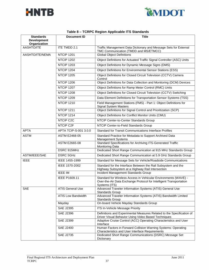
Final Regional ITS Architecture and Deployment Plan June 2011
TCRPC 37
Table 8 – TCRPC Region Applicable ITS Standards
Standards Development Organization
Document ID Title
AASHTO/ITE ITE TMDD 2.1 Traffic Management Data Dictionary and Message Sets for External TMC Communication (TMDD and MS/ETMCC)
AASHTO/ITE/NEMA NTCIP 1201 Global Object Definitions
NTCIP 1202 Object Definitions for Actuated Traffic Signal Controller (ASC) Units
NTCIP 1203 Object Definitions for Dynamic Message Signs (DMS)
NTCIP 1204 Object Definitions for Environmental Sensor Stations (ESS)
NTCIP 1205 Object Definitions for Closed Circuit Television (CCTV) Camera Control
NTCIP 1206 Object Definitions for Data Collection and Monitoring (DCM) Devices
NTCIP 1207 Object Definitions for Ramp Meter Control (RMC) Units
NTCIP 1208 Object Definitions for Closed Circuit Television (CCTV) Switching
NTCIP 1209 Data Element Definitions for Transportation Sensor Systems (TSS)
NTCIP 1210 Field Management Stations (FMS) - Part 1: Object Definitions for Signal System Masters
NTCIP 1211 Object Definitions for Signal Control and Prioritization (SCP)
NTCIP 1214 Object Definitions for Conflict Monitor Units (CMU)
NTCIP C2C NTCIP Center-to-Center Standards Group
NTCIP C2F NTCIP Center-to-Field Standards Group
APTA APTA TCIP-S-001 3.0.0 Standard for Transit Communications Interface Profiles
ASTM ASTM E2468-05 Standard Practice for Metadata to Support Archived Data Management Systems
ASTM E2665-08 Standard Specifications for Archiving ITS-Generated Traffic Monitoring Data
DSRC 915MHz Dedicated Short Range Communication at 915 MHz Standards Group
ASTM/IEEE/SAE DSRC 5GHz Dedicated Short Range Communication at 5.9 GHz Standards Group
IEEE IEEE 1455-1999 Standard for Message Sets for Vehicle/Roadside Communications
IEEE 1570-2002 Standard for the Interface Between the Rail Subsystem and the Highway Subsystem at a Highway Rail Intersection
IEEE IM Incident Management Standards Group
IEEE P1609.11 Standard for Wireless Access in Vehicular Environments (WAVE) - Over-the-Air Data Exchange Protocol for Intelligent Transportation Systems (ITS)
SAE ATIS General Use Advanced Traveler Information Systems (ATIS) General Use Standards Group
ATIS Low Bandwidth Advanced Traveler Information Systems (ATIS) Bandwidth Limited Standards Group
Mayday On-board Vehicle Mayday Standards Group
SAE J2395 ITS In-Vehicle Message Priority
SAE J2396 Definitions and Experimental Measures Related to the Specification of Driver Visual Behavior Using Video Based Techniques
SAE J2399 Adaptive Cruise Control (ACC) Operating Characteristics and User Interface
SAE J2400 Human Factors in Forward Collision Warning Systems: Operating Characteristics and User Interface Requirements
SAE J2735 Dedicated Short Range Communications (DSRC) Message Set Dictionary
Final Regional ITS Architecture and Deployment Plan June 2011
TCRPC 38
4.3 Operational Concepts
An operational concept documents each stakeholder’s current and future roles and responsibilities
across a range of transportation services. Those services are grouped in the Operational Concepts
section of Turbo Architecture. The services covered are:
Surface Street Management – The development of signal systems that react to changing
traffic conditions and provide coordinated intersection timing over a corridor, an area, or
multiple jurisdictions.
Freeway Management – The development of systems to monitor freeway (or tollway)
traffic flow and roadway conditions, and to provide strategies such as ramp metering or
lane access control to improve the flow of traffic on the freeway. Includes systems to
provide information to travelers on the roadway.
Incident Management – The development of systems to provide rapid and effective
response to incidents. Includes systems to detect and verify incidents, along with
coordinated agency response to the incidents.
Emergency Management – The development of systems to provide emergency call
taking, public safety dispatch, and emergency operations center operations.
Maintenance and Construction Management – The development of systems to manage
the maintenance of roadways in the Region, including winter weather maintenance
operations. Includes the management of construction operations.
Transit Services – The development of systems to more efficiently manage fleets of
transit vehicles or transit rail. Includes systems to provide transit traveler information both
before and during the trip.
Parking Management – The development of systems to provide vehicle parking
management for use by the driver, traveler, and other agencies.
Commercial Vehicle Operations – The development of systems to facilitate the
management of commercial vehicles (e.g., electronic clearance).
Traveler Information – The development of systems to provide static and real-time
transportation information to travelers.
Archived Data Systems – The development of systems to collect transportation data for
use in non-operational purposes (e.g., planning and research).
Table 9 identifies the roles and responsibilities of key stakeholders for a range of transportation
services. The roles and responsibilities contained within the regional ITS architecture are focused
at the regional level and do not include the level of detail associated with a project
implementation. Once a project is identified for deployment, the stakeholders involved still must
develop a more detailed Concept of Operations that is specific to technology and geographic
boundaries of that deployment.
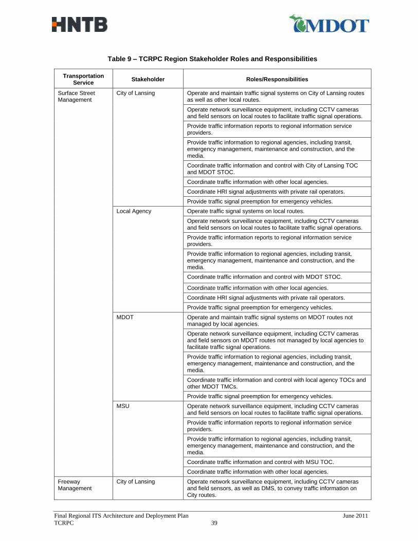
Final Regional ITS Architecture and Deployment Plan June 2011
TCRPC 39
Table 9 – TCRPC Region Stakeholder Roles and Responsibilities
Transportation Service
Stakeholder Roles/Responsibilities
Surface Street Management
City of Lansing Operate and maintain traffic signal systems on City of Lansing routes as well as other local routes.
Operate network surveillance equipment, including CCTV cameras and field sensors on local routes to facilitate traffic signal operations.
Provide traffic information reports to regional information service providers.
Provide traffic information to regional agencies, including transit, emergency management, maintenance and construction, and the media.
Coordinate traffic information and control with City of Lansing TOC and MDOT STOC.
Coordinate traffic information with other local agencies.
Coordinate HRI signal adjustments with private rail operators.
Provide traffic signal preemption for emergency vehicles.
Local Agency Operate traffic signal systems on local routes.
Operate network surveillance equipment, including CCTV cameras and field sensors on local routes to facilitate traffic signal operations.
Provide traffic information reports to regional information service providers.
Provide traffic information to regional agencies, including transit, emergency management, maintenance and construction, and the media.
Coordinate traffic information and control with MDOT STOC.
Coordinate traffic information with other local agencies.
Coordinate HRI signal adjustments with private rail operators.
Provide traffic signal preemption for emergency vehicles.
MDOT Operate and maintain traffic signal systems on MDOT routes not managed by local agencies.
Operate network surveillance equipment, including CCTV cameras and field sensors on MDOT routes not managed by local agencies to facilitate traffic signal operations.
Provide traffic information to regional agencies, including transit, emergency management, maintenance and construction, and the media.
Coordinate traffic information and control with local agency TOCs and other MDOT TMCs.
Provide traffic signal preemption for emergency vehicles.
MSU Operate network surveillance equipment, including CCTV cameras and field sensors on local routes to facilitate traffic signal operations.
Provide traffic information reports to regional information service providers.
Provide traffic information to regional agencies, including transit, emergency management, maintenance and construction, and the media.
Coordinate traffic information and control with MSU TOC.
Coordinate traffic information with other local agencies.
Freeway Management
City of Lansing Operate network surveillance equipment, including CCTV cameras and field sensors, as well as DMS, to convey traffic information on City routes.
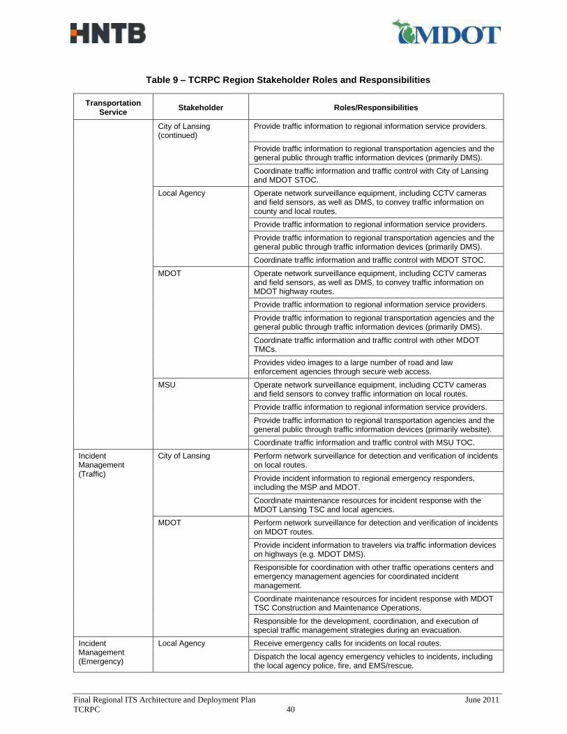
Final Regional ITS Architecture and Deployment Plan June 2011
TCRPC 40
Table 9 – TCRPC Region Stakeholder Roles and Responsibilities
Transportation Service
Stakeholder Roles/Responsibilities
City of Lansing (continued)
Provide traffic information to regional information service providers.
Provide traffic information to regional transportation agencies and the general public through traffic information devices (primarily DMS).
Coordinate traffic information and traffic control with City of Lansing and MDOT STOC.
Local Agency Operate network surveillance equipment, including CCTV cameras and field sensors, as well as DMS, to convey traffic information on county and local routes.
Provide traffic information to regional information service providers.
Provide traffic information to regional transportation agencies and the general public through traffic information devices (primarily DMS).
Coordinate traffic information and traffic control with MDOT STOC.
MDOT Operate network surveillance equipment, including CCTV cameras and field sensors, as well as DMS, to convey traffic information on MDOT highway routes.
Provide traffic information to regional information service providers.
Provide traffic information to regional transportation agencies and the general public through traffic information devices (primarily DMS).
Coordinate traffic information and traffic control with other MDOT TMCs.
Provides video images to a large number of road and law enforcement agencies through secure web access.
MSU Operate network surveillance equipment, including CCTV cameras and field sensors to convey traffic information on local routes.
Provide traffic information to regional information service providers.
Provide traffic information to regional transportation agencies and the general public through traffic information devices (primarily website).
Coordinate traffic information and traffic control with MSU TOC.
Incident Management (Traffic)
City of Lansing Perform network surveillance for detection and verification of incidents on local routes.
Provide incident information to regional emergency responders, including the MSP and MDOT.
Coordinate maintenance resources for incident response with the MDOT Lansing TSC and local agencies.
MDOT Perform network surveillance for detection and verification of incidents on MDOT routes.
Provide incident information to travelers via traffic information devices on highways (e.g. MDOT DMS).
Responsible for coordination with other traffic operations centers and emergency management agencies for coordinated incident management.
Coordinate maintenance resources for incident response with MDOT TSC Construction and Maintenance Operations.
Responsible for the development, coordination, and execution of special traffic management strategies during an evacuation.
Incident Management (Emergency)
Local Agency Receive emergency calls for incidents on local routes.
Dispatch the local agency emergency vehicles to incidents, including the local agency police, fire, and EMS/rescue.
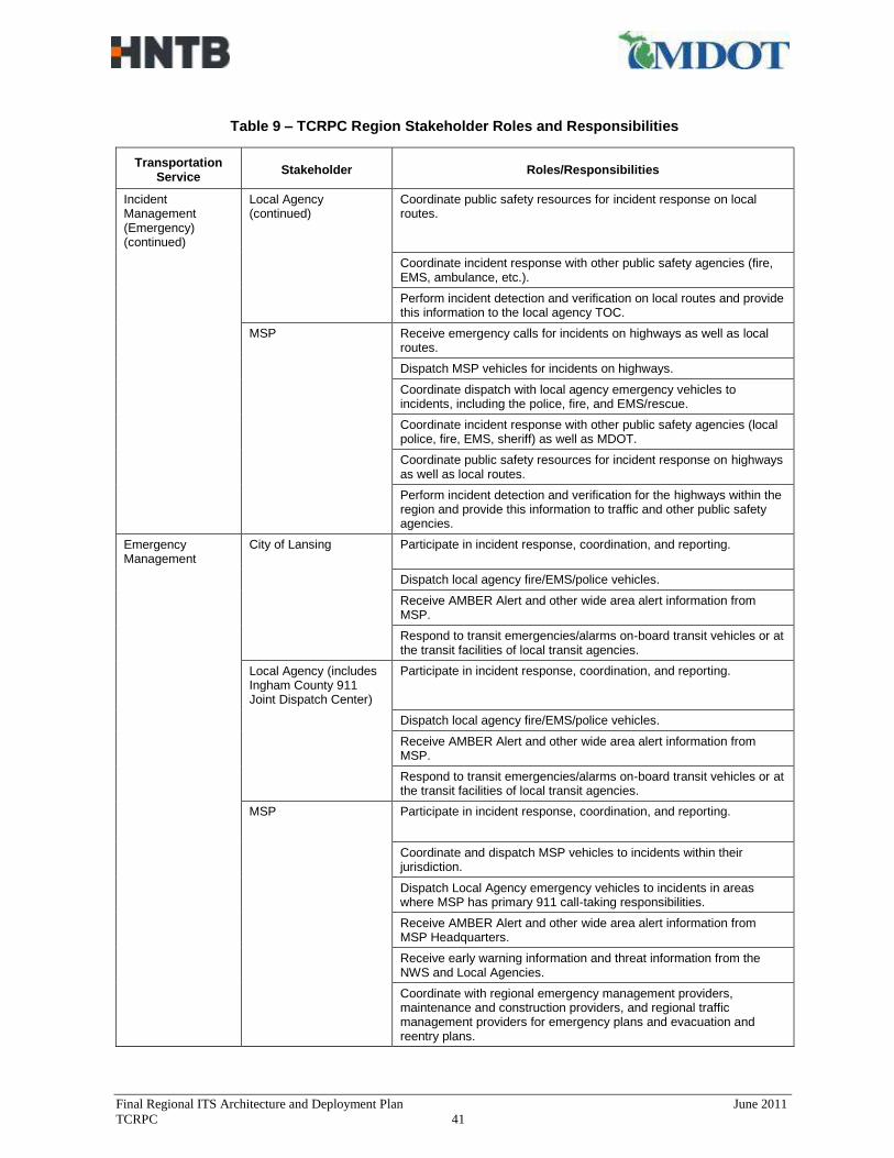
Final Regional ITS Architecture and Deployment Plan June 2011
TCRPC 41
Table 9 – TCRPC Region Stakeholder Roles and Responsibilities
Transportation Service
Stakeholder Roles/Responsibilities
Incident Management (Emergency) (continued)
Local Agency (continued)
Coordinate public safety resources for incident response on local routes.
Coordinate incident response with other public safety agencies (fire, EMS, ambulance, etc.).
Perform incident detection and verification on local routes and provide this information to the local agency TOC.
MSP Receive emergency calls for incidents on highways as well as local routes.
Dispatch MSP vehicles for incidents on highways.
Coordinate dispatch with local agency emergency vehicles to incidents, including the police, fire, and EMS/rescue.
Coordinate incident response with other public safety agencies (local police, fire, EMS, sheriff) as well as MDOT.
Coordinate public safety resources for incident response on highways as well as local routes.
Perform incident detection and verification for the highways within the region and provide this information to traffic and other public safety agencies.
Emergency Management
City of Lansing Participate in incident response, coordination, and reporting.
Dispatch local agency fire/EMS/police vehicles.
Receive AMBER Alert and other wide area alert information from MSP.
Respond to transit emergencies/alarms on-board transit vehicles or at the transit facilities of local transit agencies.
Local Agency (includes Ingham County 911 Joint Dispatch Center)
Participate in incident response, coordination, and reporting.
Dispatch local agency fire/EMS/police vehicles.
Receive AMBER Alert and other wide area alert information from MSP.
Respond to transit emergencies/alarms on-board transit vehicles or at the transit facilities of local transit agencies.
MSP
Participate in incident response, coordination, and reporting.
Coordinate and dispatch MSP vehicles to incidents within their jurisdiction.
Dispatch Local Agency emergency vehicles to incidents in areas where MSP has primary 911 call-taking responsibilities.
Receive AMBER Alert and other wide area alert information from MSP Headquarters.
Receive early warning information and threat information from the NWS and Local Agencies.
Coordinate with regional emergency management providers, maintenance and construction providers, and regional traffic management providers for emergency plans and evacuation and reentry plans.
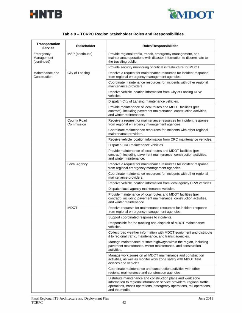
Final Regional ITS Architecture and Deployment Plan June 2011
TCRPC 42
Table 9 – TCRPC Region Stakeholder Roles and Responsibilities
Transportation Service
Stakeholder Roles/Responsibilities
Emergency Management (continued)
MSP (continued) Provide regional traffic, transit, emergency management, and maintenance operations with disaster information to disseminate to the traveling public.
Provide security monitoring of critical infrastructure for MDOT.
Maintenance and Construction
City of Lansing Receive a request for maintenance resources for incident response from regional emergency management agencies.
Coordinate maintenance resources for incidents with other regional maintenance providers.
Receive vehicle location information from City of Lansing DPW vehicles.
Dispatch City of Lansing maintenance vehicles.
Provide maintenance of local routes and MDOT facilities (per contract), including pavement maintenance, construction activities, and winter maintenance.
County Road Commission
Receive a request for maintenance resources for incident response from regional emergency management agencies.
Coordinate maintenance resources for incidents with other regional maintenance providers.
Receive vehicle location information from CRC maintenance vehicles.
Dispatch CRC maintenance vehicles.
Provide maintenance of local routes and MDOT facilities (per contract), including pavement maintenance, construction activities, and winter maintenance.
Local Agency Receive a request for maintenance resources for incident response from regional emergency management agencies.
Coordinate maintenance resources for incidents with other regional maintenance providers.
Receive vehicle location information from local agency DPW vehicles.
Dispatch local agency maintenance vehicles.
Provide maintenance of local routes and MDOT facilities (per contract), including pavement maintenance, construction activities, and winter maintenance.
MDOT Receive requests for maintenance resources for incident response from regional emergency management agencies.
Support coordinated response to incidents.
Responsible for the tracking and dispatch of MDOT maintenance vehicles.
Collect road weather information with MDOT equipment and distribute it to regional traffic, maintenance, and transit agencies.
Manage maintenance of state highways within the region, including pavement maintenance, winter maintenance, and construction activities.
Manage work zones on all MDOT maintenance and construction activities, as well as monitor work zone safety with MDOT field devices and vehicles.
Coordinate maintenance and construction activities with other regional maintenance and construction agencies.
Distribute maintenance and construction plans and work zone information to regional information service providers, regional traffic operations, transit operations, emergency operations, rail operations, and the media.
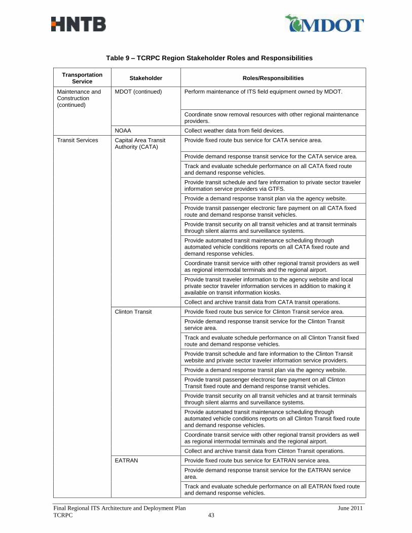
Final Regional ITS Architecture and Deployment Plan June 2011
TCRPC 43
Table 9 – TCRPC Region Stakeholder Roles and Responsibilities
Transportation Service
Stakeholder Roles/Responsibilities
Maintenance and Construction (continued)
MDOT (continued) Perform maintenance of ITS field equipment owned by MDOT.
Coordinate snow removal resources with other regional maintenance providers.
NOAA Collect weather data from field devices.
Transit Services Capital Area Transit Authority (CATA)
Provide fixed route bus service for CATA service area.
Provide demand response transit service for the CATA service area.
Track and evaluate schedule performance on all CATA fixed route and demand response vehicles.
Provide transit schedule and fare information to private sector traveler information service providers via GTFS.
Provide a demand response transit plan via the agency website.
Provide transit passenger electronic fare payment on all CATA fixed route and demand response transit vehicles.
Provide transit security on all transit vehicles and at transit terminals through silent alarms and surveillance systems.
Provide automated transit maintenance scheduling through automated vehicle conditions reports on all CATA fixed route and demand response vehicles.
Coordinate transit service with other regional transit providers as well as regional intermodal terminals and the regional airport.
Provide transit traveler information to the agency website and local private sector traveler information services in addition to making it available on transit information kiosks.
Collect and archive transit data from CATA transit operations.
Clinton Transit Provide fixed route bus service for Clinton Transit service area.
Provide demand response transit service for the Clinton Transit service area.
Track and evaluate schedule performance on all Clinton Transit fixed route and demand response vehicles.
Provide transit schedule and fare information to the Clinton Transit website and private sector traveler information service providers.
Provide a demand response transit plan via the agency website.
Provide transit passenger electronic fare payment on all Clinton Transit fixed route and demand response transit vehicles.
Provide transit security on all transit vehicles and at transit terminals through silent alarms and surveillance systems.
Provide automated transit maintenance scheduling through automated vehicle conditions reports on all Clinton Transit fixed route and demand response vehicles.
Coordinate transit service with other regional transit providers as well as regional intermodal terminals and the regional airport.
Collect and archive transit data from Clinton Transit operations.
EATRAN Provide fixed route bus service for EATRAN service area.
Provide demand response transit service for the EATRAN service area.
Track and evaluate schedule performance on all EATRAN fixed route and demand response vehicles.
Final Regional ITS Architecture and Deployment Plan June 2011
TCRPC 44
Table 9 – TCRPC Region Stakeholder Roles and Responsibilities
Transportation Service
Stakeholder Roles/Responsibilities
Transit Services (continued)
EATRAN (continued) Provide transit schedule and fare information to the EATRAN website and private sector traveler information service providers.
Provide a demand response transit plan via the agency website.
Provide transit passenger electronic fare payment on all EATRAN fixed route and demand response transit vehicles.
Provide transit security on all transit vehicles and at transit terminals through silent alarms and surveillance systems.
Provide automated transit maintenance scheduling through automated vehicle conditions reports on all EATRAN fixed route and demand response vehicles.
Coordinate transit service with other regional transit providers as well as regional intermodal terminals and the regional airport.
Collect and archive transit data from EATRAN operations.
Regional Demand Response Transit Providers
Provide demand response transit service for the Regional Demand Response Transit Providers.
Track and evaluate schedule performance on all Regional Demand Response Transit Providers’ transit vehicles.
Provide transit schedule and fare information to the Regional Demand Response Transit Providers website and private sector traveler information service providers.
Provide transit passenger electronic fare payment on all Regional Demand Response Transit Providers’ transit vehicles.
Provide transit security on all transit vehicles and at transit terminals through silent alarms and surveillance systems.
Provide automated transit maintenance scheduling through automated vehicle conditions reports on all Regional Demand Response Transit Providers’ demand response vehicles.
Collect and archive transit data from Regional Demand Response Transit Providers transit operations.
Parking Management
Capital Region Airport Authority
Manage airport DMS to display messages to travelers (number of spaces, entrance location, current charges, etc.).
Maintain parking lot information (static and dynamic).
City of Lansing Manage City of Lansing DMS to display messages to travelers (number of spaces, entrance location, current charges, etc.).
Maintain parking lot information (static and dynamic).
East Lansing Manage City of East Lansing DMS to display messages to travelers (number of spaces, entrance location, current charges, etc.).
Maintain parking lot information (static and dynamic).
Other Agencies Manage local DMS to display messages to travelers (number of spaces, entrance location, current charges, etc.).
Maintain parking lot information (static and dynamic).
Commercial Vehicle Operations
MDOT Provide credential information, safety status information, driver records, and citations to roadside check facilities.
Provide automated weigh-in-motion inspections for private fleet operations.
Provide data concerning commercial vehicle safety and credentials into profiles.
Traveler Information
City of Lansing Collect traffic information (road network conditions), work zone information, travel times, and weather information.
Final Regional ITS Architecture and Deployment Plan June 2011
TCRPC 45
Table 9 – TCRPC Region Stakeholder Roles and Responsibilities
Transportation Service
Stakeholder Roles/Responsibilities
Traveler Information (continued)
City of Lansing (continued)
Coordinate and share traveler information with all other traveler information providers within the region.
Local Agency Collect traffic information (road network conditions), work zone information, travel times, and weather information.
Coordinate and share traveler information with all other traveler information providers within the region.
MDOT Collection, processing, storage, and broadcast dissemination of traffic, transit, maintenance and construction, and weather information to travelers via MI Drive website.
Provide traveler information to private travelers through in vehicle and personal computing devices upon request.
Provide traveler information to the media.
Archived Data Management
MDOT Collect and archive asset status information from all MDOT maintenance offices and MDOT asset management systems.
Collect and archive traffic information from regional traffic management providers and centers, emergency information from MSP and Local Agency Police, and transit information from regional transit agencies for planning purposes.
Coordinate with MDOT Transportation Planning Division.
TCRPC Collect and archive traffic information from regional traffic management providers and centers, emergency information from MSP and Local Agency Police, and transit information from regional transit agencies for planning purposes.
Coordinate with MDOT Transportation Planning Division.
Collect and archive emergency and incident information from MSP and the region’s emergency responders.
Final Regional ITS Architecture and Deployment Plan June 2011
TCRPC 46
4.4 Potential Agreements
The TCRPC Regional ITS Architecture has identified many agency interfaces, information
exchanges, and integration strategies that would be needed to provide the ITS services and
systems identified by the stakeholders in the Region. Interfaces and data flows among public and
private entities in the Region will require agreements among agencies that establish parameters
for sharing agency information to support traffic management, incident management, provide
traveler information, and perform other functions identified in the regional ITS architecture.
Integrating systems from two or more agencies combined with the anticipated level of
information exchange identified in the architecture will require the implementation of ITS
technologies along with subsequent formal agreements between agencies. These agreements,
while perhaps not requiring a financial commitment from agencies in the Region, should outline
specific roles, responsibilities, data exchanges, levels of authority, and other facets of regional
operations. Some agreements also will outline specific funding responsibilities, where appropriate
and applicable.
Agreements should avoid being specific with regards to technology when possible. Technology is
likely to change rapidly and changes to technology could require an update of the agreement if
the agreement was not technology neutral. The focus of the agreement should be on the
responsibilities of the agencies and the high level information that needs to be exchanged.
Depending on the type of agreement being used, agencies should be prepared for the process to
complete an agreement to take several months or years. Agencies must first reach consensus on
what should be in an agreement and then proceed through the approval process. The approval
process for formal agreements varies by agency and can often be quite lengthy, so it is
recommended that agencies plan ahead to ensure that the agreement does not delay the project.
When implementing an agreement for ITS, it is recommended that, as a first step, any existing
agreements are reviewed to determine whether they can be amended or modified to include the
additional requirements that will come with deploying a system. If there are no existing
agreements that can be modified or used for ITS implementation, then a new agreement will need
to be developed. The formality and type of agreement used is a key consideration. If the
arrangement will be in effect for an extended duration or involve any sort of long term
maintenance, then written agreements should be used. Often during long term operations, staff
may change and a verbal agreement between agency representatives may be forgotten by new
staff.
Common agreement types and potential applications include:
Handshake Agreement: Handshake agreements are often used in the early stage of a
project. This type of informal agreement depends very much on relationships between
agencies and may not be appropriate for long term operations where staff is likely to
change.
Memorandum of Understanding (MOU): A MOU demonstrates general consensus or
willingness to participate as part of a particular project, but is not typically very detailed.
Interagency and Intergovernmental Agreements: These agreements between public
agencies can be used for operation, maintenance, or funding of its projects and systems.
They can include documentation on the responsibility of each agency, functions they will
provide, and liability.
Funding Agreements: Funding agreements document the funding arrangements for ITS
projects. At a minimum, funding agreements include a detailed scope, services to be
performed, and a detailed project budget.
Final Regional ITS Architecture and Deployment Plan June 2011
TCRPC 47
Master Agreements: Master agreements include standard contract language for an
agency and serve as the main agreement between two entities which guides all business
transactions. Use of a master agreement can allow an agency to do business with another
agency or private entity without having to go through the often lengthy development of a
formal agreement each time.
Table 10 provides a list of existing and potential agreements for the TCRPC Region based on the
interfaces identified in the regional ITS architecture. It is important to note that as ITS services
and systems are implemented in the Region, part of the planning and review process for those
projects should include a review of potential agreements that would be needed for
implementation or operations.
Table 10 – TCRPC Region Potential Agreements
Status Agreement and
Agencies Agreement Description
Future Joint Operations/Shared Control Agreements (Public-Public or Public-Private)
These agreements would allow joint operations or control of certain systems and equipment. The agreement should define such items as hours of operation and time of day/day of week when shared control would take effect, circumstances, or incidents when shared control would take effect, notification procedures between the agencies agreeing to share control arrangements, overriding capabilities of owning agency, etc. Private agencies, such as information service providers that provide traffic reports, could also be part of this agreement.
Future Data Sharing and Usage (Public-Public)
These agreements would define the parameters, guidelines, and policies for inter- and intra-agency ITS data sharing. This data sharing would support regional activities related to traffic management, incident management, traveler information, and other functions. The terms of this agreement should generally address such items as types of data and information to be shared, how the information will be used (traffic incident information to be shared, displayed on web site for travel information, distributed to private media, etc.), and parameters for data format, quality, and security.
Future Data Sharing and Usage (Public-Private)
These agreements would define the parameters, guidelines, and policies for private sector (such as the media or other information service providers) use of ITS data. This type of agreement is recommended to define terms of use for broadcasting public-agency information regarding traffic conditions, closures, restrictions, as well as video images. Agreements also can include requirements for the media to ‘source’ the information (i.e., using the providing agency’s logo on all video images broadcast.
Future Mutual Aid Agreements (Public-Public)
Mutual aid agreements often exist as either formal or informal arrangements. They are a routine practice among many public safety and emergency services agencies. Formal mutual aid agreements will become more important as agencies integrate systems and capabilities, particularly automated dispatch and notification. Formalized agreements should be considered as ITS or other electronic data sharing systems are implemented in the Region.
Table 11 presents a summary of existing and proposed agreements for the TCRPC region. These
agreements either exist and are maintained by the partnering agencies or are identified as needed
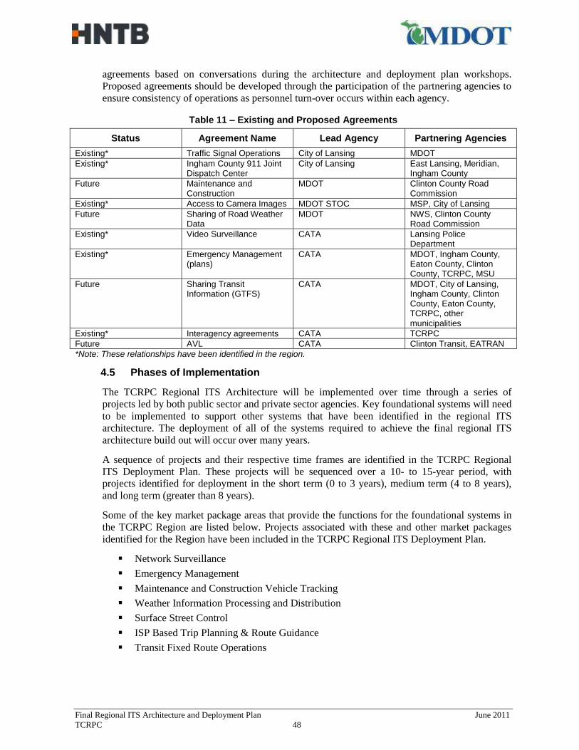
Final Regional ITS Architecture and Deployment Plan June 2011
TCRPC 48
agreements based on conversations during the architecture and deployment plan workshops.
Proposed agreements should be developed through the participation of the partnering agencies to
ensure consistency of operations as personnel turn-over occurs within each agency.
Table 11 – Existing and Proposed Agreements
Status Agreement Name Lead Agency Partnering Agencies
Existing* Traffic Signal Operations City of Lansing MDOT
Existing* Ingham County 911 Joint Dispatch Center
City of Lansing East Lansing, Meridian, Ingham County
Future
Maintenance and Construction
MDOT Clinton County Road Commission
Existing* Access to Camera Images MDOT STOC MSP, City of Lansing
Future Sharing of Road Weather Data
MDOT NWS, Clinton County Road Commission
Existing* Video Surveillance CATA Lansing Police Department
Existing* Emergency Management (plans)
CATA MDOT, Ingham County, Eaton County, Clinton County, TCRPC, MSU
Future Sharing Transit Information (GTFS)
CATA MDOT, City of Lansing, Ingham County, Clinton County, Eaton County, TCRPC, other municipalities
Existing* Interagency agreements CATA TCRPC
Future AVL CATA Clinton Transit, EATRAN
*Note: These relationships have been identified in the region.
4.5 Phases of Implementation
The TCRPC Regional ITS Architecture will be implemented over time through a series of
projects led by both public sector and private sector agencies. Key foundational systems will need
to be implemented to support other systems that have been identified in the regional ITS
architecture. The deployment of all of the systems required to achieve the final regional ITS
architecture build out will occur over many years.
A sequence of projects and their respective time frames are identified in the TCRPC Regional
ITS Deployment Plan. These projects will be sequenced over a 10- to 15-year period, with
projects identified for deployment in the short term (0 to 3 years), medium term (4 to 8 years),
and long term (greater than 8 years).
Some of the key market package areas that provide the functions for the foundational systems in
the TCRPC Region are listed below. Projects associated with these and other market packages
identified for the Region have been included in the TCRPC Regional ITS Deployment Plan.
Network Surveillance
Emergency Management
Maintenance and Construction Vehicle Tracking
Weather Information Processing and Distribution
Surface Street Control
ISP Based Trip Planning & Route Guidance
Transit Fixed Route Operations
Final Regional ITS Architecture and Deployment Plan June 2011
TCRPC 49
4.6 Incorporation into the Regional Planning Process
As an MPO, TCRPC is responsible for coordinating transportation planning and programming
activities among the variety of transportation agencies and stakeholders involved in the Tri-
county metropolitan area. To date, TCRPC has been active in the development and administration
of the region’s ITS Architecture and has been involved in ITS on a variety of levels. The TCRPC
has established the Management and Operations Task Force to oversee the identification,
selection, and implementation of ITS solutions in the region. This Task Force reviews project
requests to ensure consistency with the TCRPC Regional ITS Architecture. Figure 11 shows the
task force within the overall TCRPC Committee structure.
The TCRPC adopted the Regional 2035 Transportation Plan on January 21, 2010. This plan has
clearly outlined the process of strategic planning and implementation of ITS in the Tri-county
region. In lieu of creating multiple locations that document the ITS Planning Process in place for
the Tri-county stakeholders, the regional ITS architecture references Chapter 13 of the Plan.
Beginning with page 13-219, the Plan provides a very in-depth overview of the process required
to fund and implement a project in the Region.
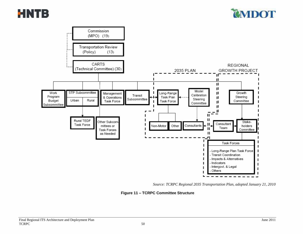
Final Regional ITS Architecture and Deployment Plan June 2011
TCRPC 50
Source: TCRPC Regional 2035 Transportation Plan, adopted January 21, 2010
Figure 11 – TCRPC Committee Structure
Final Regional ITS Architecture and Deployment Plan June 2011
TCRPC 51
5 Use and Maintenance Plan for the Regional ITS Architecture The update of the TCRPC Regional ITS Architecture addresses the Region’s vision for ITS
implementation at the time the document was completed. As the Region grows, needs will change, and,
as technology progresses, new ITS opportunities will arise. Shifts in regional needs and focus, as well as
changes in the National ITS Architecture, will necessitate that the regional ITS architecture be
maintained and updated to remain a useful resource for the Region.
This section provides guidance for maintaining and using the regional ITS architecture for implementing
projects; where appropriate, this section references the ITS deployment plan. Further detailed guidance
on the maintenance of the ITS deployment plan is presented within that document. It is recommended
that a comprehensive update to the regional ITS architecture occur concurrently with an update of the
ITS deployment plan since the success of both of these documents relies on stakeholder involvement and
regional ITS goals. However, it is important to note, that even though an ITS deployment plan provides
great value to the ITS investment in the Region, only the ITS architecture is a federal requirement.
Updates to the TCRPC Regional ITS Architecture will occur on a regular basis as described in Section
5.1 to maintain the regional ITS architecture as a useful planning tool. Between complete plan updates,
smaller modifications likely will be required to accommodate ITS projects in the Region. Section 5.2
provides a step-by-step process to guide stakeholders in determining whether or not a project requires
regional ITS architecture modifications.
5.1 Maintenance Process
MDOT’s ITS Program Office will work closely with TCRPC to maintain the TCRPC Regional
ITS Architecture. Maintenance includes the oversight and management of modifications submitted
by stakeholders as well as complete updates of the regional ITS architecture. Documenting
modifications occurring between major updates will improve their efficiency. As element names or
flows change due to the implementation of projects, simply documenting these impacts to the
regional ITS architecture addresses the federal requirement for maintenance. It is recommended
that complete updates to the regional ITS architecture occur in tandem with a complete update to
the ITS Deployment Plan to capture the potential influences newly identified projects could
introduce to the architecture. Additionally, concurrent updates of both documents help
stakeholders to appropriately capture projects based on regional needs. Table 12 summarizes the
maintenance process for both the architecture and deployment plan.
Complete updates to the regional ITS architecture will occur approximately every five to seven
years and will be led by the MDOT ITS Program Office with support from TCRPC and other
regional stakeholders. The entire stakeholder group that was engaged to update this revision of the
regional ITS architecture should be reconvened for the complete updates.
Final Regional ITS Architecture and Deployment Plan June 2011
TCRPC 52
Table 12 – Regional ITS Architecture and Deployment Plan Maintenance Summary
Maintenance Details
Regional ITS Architecture Regional ITS Deployment Plan
Modification Complete
Update Modification
Complete Update
Timeframe for Updates
As needed Every 5-7 years As needed Every 5-7 years
Scope of Update
Update market packages to
satisfy architecture conformance
requirements of projects or to
document other changes that impact the
Regional ITS Architecture
Entire Regional ITS Architecture
Update project status and add or remove projects
as needed
Entire Regional ITS Deployment
Plan
Lead Agency MDOT ITS Program Office/TCRPC MDOT ITS Program Office/TCRPC
Participants
Stakeholders impacted by
market package modifications
Entire stakeholder group
Stakeholders impacted by
project modifications
Entire stakeholder group
Results
Market package or other change(s) documented for next complete
update
Updated Regional ITS Architecture
document, Appendices, and
Turbo Architecture database
Updated project tables
Updated Regional ITS Deployment Plan document
* Transit related projects will be supported by MDOT’s Bureau of Passenger Transportation
5.1.1 ITS Architecture Changes between Scheduled Updates
For situations where a change is required, a Regional ITS Architecture Conformance and
Maintenance Documentation Form was developed and is included in Appendix E. This form
should be completed and submitted to the MDOT ITS Program Office and to the TCRPC
Office whenever a change to the regional ITS architecture is proposed.
Noted on the form are additional agencies that need to be copied in specific instances. If the
project is located within the TCRPC region, then TCRPC also should receive a copy of the
form. If the project has a transit related component, MDOT’s Bureau of Passenger
Transportation also should be copied.
The Regional ITS Architecture Conformance and Maintenance Documentation Form
identifies three levels of modifications.
Level 1 – Basic changes that do not affect the structure of the architecture.
Examples include: Changes to the name or status of a stakeholder or element, or the
status of a data flow.
Level 2 – Structural changes that impact only one agency.
Examples include: Addition of a new market package or modifications to an existing
market package that affects only one agency.
Final Regional ITS Architecture and Deployment Plan June 2011
TCRPC 53
Level 3 – Structural changes that have the potential to impact multiple agencies.
Examples include: New market package additions or existing market package
modifications that involve multiple agencies or incorporate a new stakeholder into the
architecture.
MDOT’s ITS Program Office and TCRPC will review and accept the proposed changes. All
changes will be documented for incorporation during the next complete regional ITS
architecture update performed by MDOT’s ITS Program Office. Figure 12 illustrates this
process.
Project Manager Evaluates
Conformance to Regional ITS
Architecture
Project Manager Completes
Regional ITS Architecture
Conformance and Maintenance
Documentation Form and Submits
to ITS Program Office and TCRPC
ITS Program Office Submits
Approved Form to FHWA,
Regional Contact, and Project
Manager
ITS Program Office
Coordinates with the Project
Manager and Regional
Coordinator
APPROVED
Yes
No
Figure 12 – Process for Documenting Architecture Performance
Final Regional ITS Architecture and Deployment Plan June 2011
TCRPC 54
5.2 Process for Determining and Documenting Architecture Conformity
The life of an ITS project includes numerous steps from concept to reality. As the project moves
from an idea to implementation following an MDOT process, it parallels the federally required
systems engineering (SE) process. One of the first steps within the SE process is aligning the
project with the architecture and identifying regional ITS architecture components. As Figure 13
shows, these steps occur very early for both the MDOT and SE processes.
TIME
Sy
ste
ms
En
gin
ee
rin
g
Pro
ce
ss
Lif
e o
f a
n IT
S
Pro
jec
t
Construction AcceptanceProject
Scope
IPO 3-Year Call for Projects
System
Design
Phase
Requirements Testing
ITS
Standards
Regional
Deployment
Plan
Operations
and
Maintenance
ITS Regional
ArchitectureRoles &
Responsibilities
Concept of
Operations
Definition of
Requirements
Analysis of
Alternative
Configurations
LETTING
Procurement
OptionsID Regional
Architecture
Components
Figure 13 – Life of an ITS Project (excerpt from the Basis of Design Document (BODD)
This section provides stakeholders with step-by-step guidance through the development of a
project to ensure it is in conformance with the regional ITS architecture. The stakeholders should
work with the MDOT IPO, TCRPC, and any additional agencies involved in the project or its
update.
Figure 14 illustrates steps the stakeholders will need to follow to determine the regional ITS
architecture’s conformity. For stakeholders that are less familiar with documenting the conformity,
a checklist has been developed for guidance. The content for the Regional ITS Architecture
Conformance and Maintenance Documentation Form can come directly from the checklist
information. Both the checklist and form can be found in Appendix E.
Final Regional ITS Architecture and Deployment Plan June 2011
TCRPC 55
Identify ALL
components
in the project
Are ALL market
packages and
components in the
architecture?
Stakeholder name
or status change?
Flow status
change?
Element name or
status change?
No updates
are needed,
the project is
in
conformance
Yes or No?
Indicate the
components for
updates
Level I update – refer to
Regional ITS Architecture
Conformance and
Maintenance Documentation
FormAdditional agencies
affected?
Indicate all updates:
New stakeholder
New element
New flow
New Market
Package
Level II update – refer to
Regional ITS Architecture
Conformance and
Maintenance Documentation
Form
Affected
stakeholders
contacted?
Indicate all updates:
New stakeholder
New element
New flow
New Market
Package
Level III update – refer to
Regional ITS Architecture
Conformance and
Maintenance Documentation
Form
Contact those
affected by the
update – they
will need to be
in agreement
with the
identified
changes
Fill out the Regional ITS Architecture
Conformance and Maintenance Documentation
Form based on which level update is needed
New Project with
federal funds
Identify ALL
relevant
market
packages
Any market
packages need
modification?
Yes
Yes
Yes
No
No
No
No
Yes
NoYes
Indicate any new market
packages and/or
modifications to existing
market packages
Indicate
components
not in the
architecture
Figure 14 – Steps to Determine Architecture Conformity
Final Regional ITS Architecture and Deployment Plan June 2011
TCRPC 56
The checklist is divided into four main categories that guide the stakeholder through evaluating
and documenting conformance.
Identify ALL market packages (MPs) and ITS components relevant to the project.
Verify that ALL MPs and ITS components are contained within the architecture.
Identify modifications or additions related to MPs or ITS components.
Document the necessary changes to the regional ITS architecture to ensure conformance.
The checklist provides a set of questions and directions that should help the stakeholders establish
the information needed to complete the Regional ITS Architecture Conformance and Maintenance
Documentation Form. The following section provides additional detailed guidance on where to
find the information needed for each step of the process.
Identify ALL relevant market packages and ITS components in the project
Referencing Appendix A and Appendix B of the regional ITS architecture document, the
stakeholder will need to identify all market packages that are relevant to their project, regardless if
they are existing or new. Secondly, the stakeholder should identify all of the components within
the project, including the stakeholders, elements, and the flows between elements. Background
regarding the elements in the regional ITS architecture is presented in Section 3.3. Table 4 and
Table 5 provide information for reference regarding the stakeholders. These tables include all
existing components and their status presented in the regional ITS architecture. They also
demonstrate the information needed for any newly identified components.
Verify Whether ALL MPs and ITS components are in the Architecture
Once the stakeholder has identified all MPs and ITS components, they then will need to verify
whether or not they are included in the regional ITS architecture. The verification can be done by
comparing the result either with Turbo or by using Table 4, Table 5, or Table 6. The stakeholder
should mark those that are not included in the architecture on the checklist for Question 1.
Identify Modifications/Updates to Market Packages or ITS Components
As a next step, the stakeholder should identify whether or not any of the MPs or ITS components
require modification from their current form in the regional ITS architecture. A modification
would include a name change, a flow change or a status change (from planned to existing). Table 5
provides the existing components, descriptions, and status. Projects sometimes introduce new
elements or flows between elements or even new market packages within the architecture. The
stakeholder can reference Appendix B while developing new MPs, elements, and/or flows.
Document Required Changes
If any changes are needed to accommodate the project under review, these changes need to be
submitted using the Regional ITS Architecture Conformance and Maintenance Documentation
Form, found in Appendix E. The checklist provides guidance on assembling information required
for the form. Once the documentation of architecture changes are transferred to the form, it then is
sent to MDOT IPO. The MDOT IPO will coordinate with TCRPC on implementing and
maintaining records of changes to the regional ITS architecture. If there is a transit component to
the update, then it needs to be sent to MDOT – Bureau of Passenger Transportation and the
Federal Transit Authority (FTA). As a reminder for the stakeholder, if an existing MP is updated
or a new market package is introduced, a sketch of the modification/update needs to be attached to
the form when it is submitted.
Final Regional ITS Architecture and Deployment Plan June 2011
TCRPC 57
5.3 Relevant Standard Use
The regional ITS architecture identifies National Standards that are applicable at a regional level
based on the market packages and flows identified by the stakeholders. These standards provide a
starting point for the implementation of integrated solutions, but do not always provide an
adequate level of guidance for the individual stakeholder agency. As each market package or
solution is implemented in the region, it is important for all of the identified and potential
stakeholders to be involved. Even though some stakeholders may not be funding or implementing
current components of the project, their buy-in and support of the selected solution is integral to
the success of the project on a regional level. When those stakeholders decide to implement
expansions of a system or systems of their own that should integrate, they need to agree to the
standards identified during the initial phase.
The National Architecture does not provide specific guidance on conformance to local standards,
but this can be achieved through mutual agreements between the involved agencies. Additionally,
continuous conversations between the stakeholders through standing ITS committees provide
support and guidance to stakeholders new to ITS. The committee meetings also include newer
stakeholders in conversations around the established local standards that may already exist. As the
MDOT IPO and TCRPC review architecture and maintenance forms for the TCRPC Region, it is
important that consideration be given to the solutions identified for the project and the standards
that are selected. Close management of these standards can improve operations costs on systems
and improve the interoperability of the regional deployment of ITS, which is the goal of the
regional ITS architecture.
Final Regional ITS Architecture and Deployment Plan June 2011
TCRPC 58
6 Deployment Plan The last ITS plan developed for the Tri-County Regional Planning Commission (TCRPC) are was
developed as part of a larger MDOT Deployment Plan effort that was completed in 2002. The report
documented a wide range of ITS concepts including freeway management, arterial management and
transit ITS deployment. Since that time there have been several deployments in the region and a number
currently in the planning stage, including:
Deployment of extensive ITS technology on the Capital Area Transit Authority (CATA) system;
Development of a Traffic Management Center for the Lansing arterial system;
Deployment of a freeway management system on I-496 and I-96 east of Lansing
Ongoing deployment of a Statewide Traffic Operations Center that will serve Lansing and all
ITS deployments in Michigan outside of the Detroit and Grand Rapids regions; and
A temporary ITS system that was deployed as part of the reconstruction of I-496 through Lansing
in 2001.
These active deployment activities were discussed in more detail in Chapter 1 of this report. Chapter 1
also documents the stakeholder process that was used to generate proposed deployments for this study.
The first stakeholder meeting focused on the ITS architecture and general summary of need, while the
second focused on specific projects. Table 13 through Table 16 show the final list of projects that were
agreed upon after the second stakeholder meeting. The final set of projects were evaluated using the ITS
Deployment Analysis (IDAS) system, a package developed for FHWA for evaluating benefits and costs
of a wide range of ITS deployments. IDAS incorporates travel demand models from regional and State
agencies, which means that basic assumptions regarding the transportation network, trip generation and
trip distribution as those used by the regional and State agencies for their planning projects. A more
detailed description of the IDAS model is found later in this section. In this update, the TCRPC regional
model was incorporated into IDAS and analysis conducted year the base year of 2010 and the future year
2020. TCRPC models were not available for year 2020 so 2025 forecast models were used and the results
interpolated back to 2020. ITS analysis is generally done over a shorter timeframe than capital planning
due to several factors:
Projects usually require less lead time
The life of key ITS equipment such as CCTV and DMS is generally in the 8-15 year timeframe,
much less than that of major capital investments; and
Rapid changes in technology make any forecast beyond 10 years potentially obsolete, Connected
Vehicle technology, for example, has the potential to replace much of the current ITS technology
within in the next 10-20 years.
An important caveat on the modeling effort is that the TCRPC is a national leader in the integration of
transportation and land use planning. Their long-range planning models (2030 and 2035) include
alternatives that concentrate growth closer to urban and town centers, thus reducing trip lengths and
VMT. TCRPC has a number of initiatives ongoing with local communities in its service regions to
implement these policies. The IDAS analysis conducted for this project is only using a 10-year horizon
the model assumptions do not reflect these policy initiatives or their impacts. Because these policies
would reduce travel times and probably lead to more use of transit and non-motorized modes, they would
result in a lower level of benefits than those estimated in this study for highway ITS alternatives.
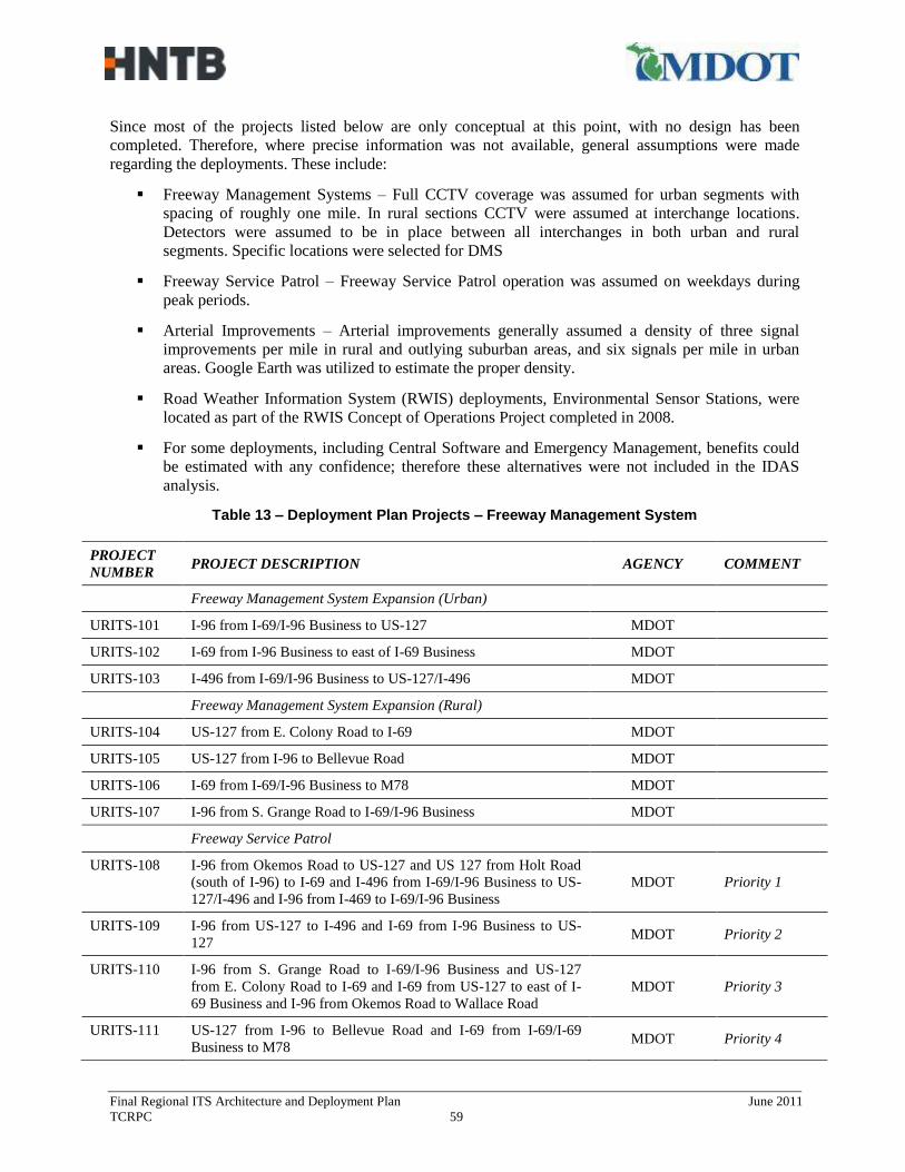
Final Regional ITS Architecture and Deployment Plan June 2011
TCRPC 59
Since most of the projects listed below are only conceptual at this point, with no design has been
completed. Therefore, where precise information was not available, general assumptions were made
regarding the deployments. These include:
Freeway Management Systems – Full CCTV coverage was assumed for urban segments with
spacing of roughly one mile. In rural sections CCTV were assumed at interchange locations.
Detectors were assumed to be in place between all interchanges in both urban and rural
segments. Specific locations were selected for DMS
Freeway Service Patrol – Freeway Service Patrol operation was assumed on weekdays during
peak periods.
Arterial Improvements – Arterial improvements generally assumed a density of three signal
improvements per mile in rural and outlying suburban areas, and six signals per mile in urban
areas. Google Earth was utilized to estimate the proper density.
Road Weather Information System (RWIS) deployments, Environmental Sensor Stations, were
located as part of the RWIS Concept of Operations Project completed in 2008.
For some deployments, including Central Software and Emergency Management, benefits could
be estimated with any confidence; therefore these alternatives were not included in the IDAS
analysis.
Table 13 – Deployment Plan Projects – Freeway Management System
PROJECT
NUMBER PROJECT DESCRIPTION AGENCY COMMENT
Freeway Management System Expansion (Urban)
URITS-101 I-96 from I-69/I-96 Business to US-127 MDOT
URITS-102 I-69 from I-96 Business to east of I-69 Business MDOT
URITS-103 I-496 from I-69/I-96 Business to US-127/I-496 MDOT
Freeway Management System Expansion (Rural)
URITS-104 US-127 from E. Colony Road to I-69 MDOT
URITS-105 US-127 from I-96 to Bellevue Road MDOT
URITS-106 I-69 from I-69/I-96 Business to M78 MDOT
URITS-107 I-96 from S. Grange Road to I-69/I-96 Business MDOT
Freeway Service Patrol
URITS-108 I-96 from Okemos Road to US-127 and US 127 from Holt Road
(south of I-96) to I-69 and I-496 from I-69/I-96 Business to US-
127/I-496 and I-96 from I-469 to I-69/I-96 Business
MDOT Priority 1
URITS-109 I-96 from US-127 to I-496 and I-69 from I-96 Business to US-
127 MDOT Priority 2
URITS-110 I-96 from S. Grange Road to I-69/I-96 Business and US-127
from E. Colony Road to I-69 and I-69 from US-127 to east of I-
69 Business and I-96 from Okemos Road to Wallace Road
MDOT Priority 3
URITS-111 US-127 from I-96 to Bellevue Road and I-69 from I-69/I-69
Business to M78 MDOT Priority 4
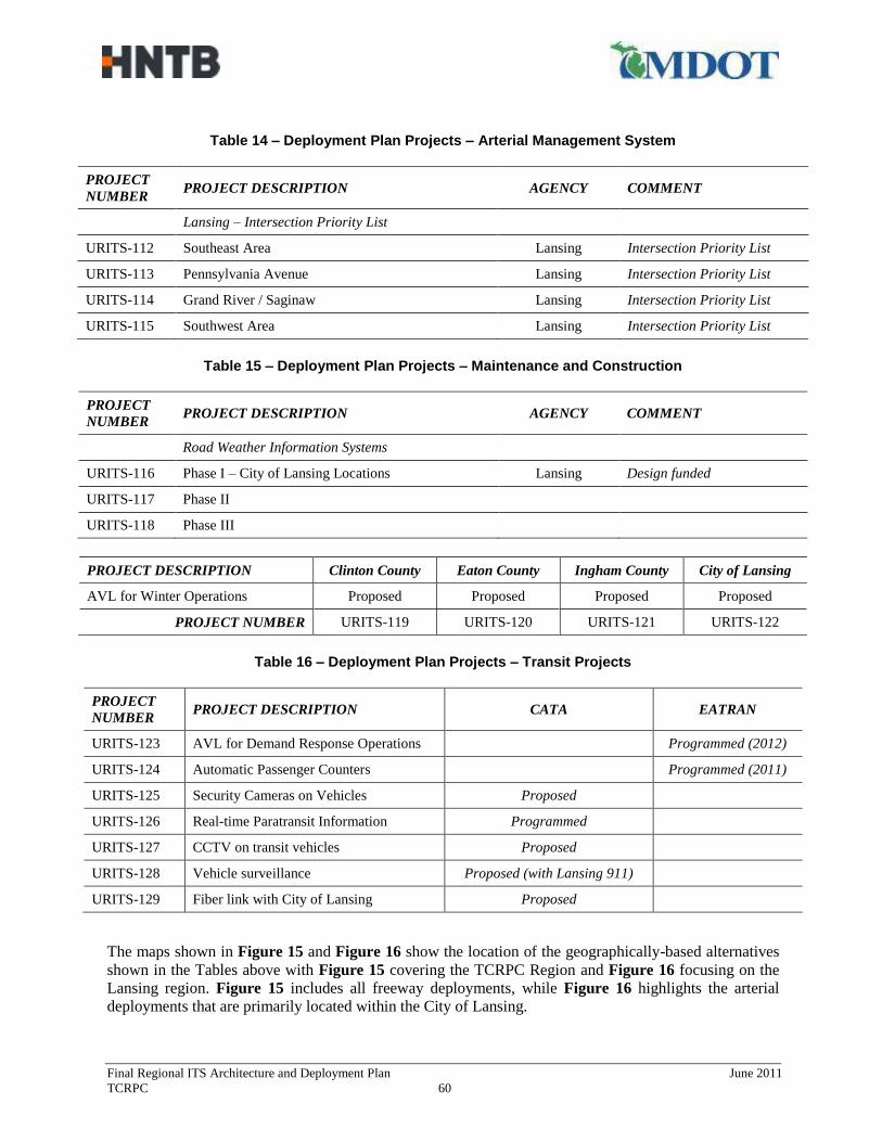
Final Regional ITS Architecture and Deployment Plan June 2011
TCRPC 60
Table 14 – Deployment Plan Projects – Arterial Management System
PROJECT
NUMBER PROJECT DESCRIPTION AGENCY COMMENT
Lansing – Intersection Priority List
URITS-112 Southeast Area Lansing Intersection Priority List
URITS-113 Pennsylvania Avenue Lansing Intersection Priority List
URITS-114 Grand River / Saginaw Lansing Intersection Priority List
URITS-115 Southwest Area Lansing Intersection Priority List
Table 15 – Deployment Plan Projects – Maintenance and Construction
PROJECT
NUMBER PROJECT DESCRIPTION AGENCY COMMENT
Road Weather Information Systems
URITS-116 Phase I – City of Lansing Locations Lansing Design funded
URITS-117 Phase II
URITS-118 Phase III
PROJECT DESCRIPTION Clinton County Eaton County Ingham County City of Lansing
AVL for Winter Operations Proposed Proposed Proposed Proposed
PROJECT NUMBER URITS-119 URITS-120 URITS-121 URITS-122
Table 16 – Deployment Plan Projects – Transit Projects
PROJECT
NUMBER PROJECT DESCRIPTION CATA EATRAN
URITS-123 AVL for Demand Response Operations Programmed (2012)
URITS-124 Automatic Passenger Counters Programmed (2011)
URITS-125 Security Cameras on Vehicles Proposed
URITS-126 Real-time Paratransit Information Programmed
URITS-127 CCTV on transit vehicles Proposed
URITS-128 Vehicle surveillance Proposed (with Lansing 911)
URITS-129 Fiber link with City of Lansing Proposed
The maps shown in Figure 15 and Figure 16 show the location of the geographically-based alternatives
shown in the Tables above with Figure 15 covering the TCRPC Region and Figure 16 focusing on the
Lansing region. Figure 15 includes all freeway deployments, while Figure 16 highlights the arterial
deployments that are primarily located within the City of Lansing.
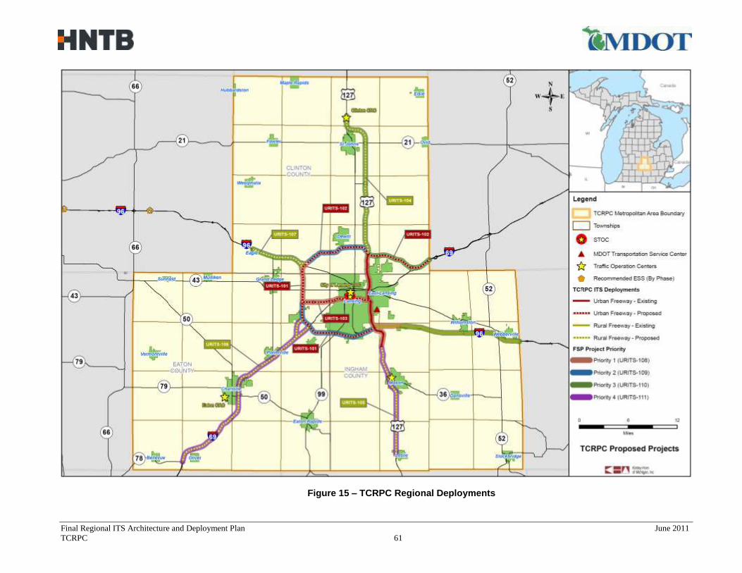
Final Regional ITS Architecture and Deployment Plan June 2011
TCRPC 61
Figure 15 – TCRPC Regional Deployments

Final Regional ITS Architecture and Deployment Plan June 2011
TCRPC 62
Figure 16 – TCRPC Region ITS Deployments – Lansing Area Blowup
Final Regional ITS Architecture and Deployment Plan June 2011
TCRPC 63
6.1 Benefit/Cost Analysis Methodology
6.1.1 IDAS Description
The most important quantitative tool used in the evaluation was the ITS Deployment
Analysis System (IDAS). This software package was used to conduct the benefit-cost
analysis of identified ITS improvements. IDAS is a sketch-planning software and analysis
methodology developed by Cambridge Systematics for the Federal Highway Administration
(FHWA).
IDAS was developed to assist state, regional, and local agencies in integrating ITS into the
transportation planning process. Planners and others can use IDAS to calculate relative costs
and benefits of ITS investments. IDAS currently predicts costs, benefits, and impacts for
more than 60 types of ITS investments.
In order to be consistent with current transportation planning processes, IDAS operates as a
post-processor to travel demand models used by Metropolitan Planning Organizations
(MPO) and by state DOTs. IDAS, although a sketch-planning tool, can implement the modal
split and/or traffic assignment steps associated with a traditional planning model. These are
key steps in estimating the changes in modal, route, and temporal decisions of travelers
resulting from ITS technologies.
The set of impacts evaluated by IDAS included changes in user mobility, travel time/speed,
travel time reliability, fuel costs, operating costs, accident costs, emissions, and noise. The
performance of selected ITS options can be viewed by market sector, facility type, and
district. Given the diverse types of performance measures that may be impacted by ITS and
the desirability of providing a comprehensive analysis tool, IDAS is comprised of five
different analysis modules as shown in Figure 17.
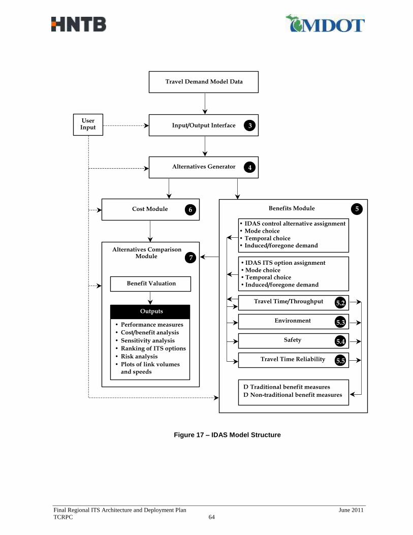
Final Regional ITS Architecture and Deployment Plan June 2011
TCRPC 64
Figure 2.25 IDAS Model Structure
Benefits Module
• IDAS control alternative assignment • Mode choice • Temporal choice • Induced/foregone demand
• IDAS ITS option assignment • Mode choice • Temporal choice • Induced/foregone demand
Travel Time/Throughput
Environment
Safety
D Traditional benefit measures
D Non-traditional benefit measures
User Input
Alternatives Generator 4
Alternatives Comparison Module
Cost Module
Outputs
• Performance measures
• Cost/benefit analysis
• Sensitivity analysis
• Ranking of ITS options
• Risk analysis
• Plots of link volumes and speeds
6
7
5
5.2
5.3
5.4
Input/Output Interface 3
Travel Demand Model Data
Benefit Valuation
Travel Time Reliability 5.5
Figure 17 – IDAS Model Structure
Final Regional ITS Architecture and Deployment Plan June 2011
TCRPC 65
6.1.2 IDAS Inputs and Default Values
For this evaluation, data outputs were obtained from the TCRPC model to use as inputs into
the IDAS model. The model data included both network files and travel demand files (trip
tables) representing daily volumes for 2010 and the forecast year 2020. As discussed in the
introduction, the TCRPC network files used for 2025, and the results interpolated back to
2020. Only highway facilities, including automobile and truck trips, were evaluated using
the models.
Other parameters, such as baseline travel time skims (zone to zone), turn prohibitors,
volume-delay curves, in- and out-of-vehicle travel times, and vehicle occupancies from the
model were incorporated into IDAS.
IDAS estimates the impacts of the various ITS deployments by drawing on a database of
default impacts for each separate ITS component. These defaults were developed by
assembling and analyzing observed impacts and evaluation results for similar deployments
across the United States.
The default impacts form the basis for the estimation of impacts on traffic, such as travel
time and speed, in the IDAS software. Impact values are applied to the model runs to
estimate the changes that occur as a result of ITS deployments. These are generally applied
to travel times or volumes in the model. For example, DMS sign parameters contain three
components:
The percentage of time that the sign is active regarding an event that impacts
downstream traffic;
The percentage of motorists who react to the information on the sign and change
their route; and
The estimated number of minutes saved by the diversion.
Parameters were derived primarily from surveys taken of commuters in the Detroit and
Lansing regions. Detroit commuters did have permanent signs available at the time of the
survey while Lansing commuters did not. Lansing commuters did have temporary signs
associated with construction however and thus were familiar with the concept. Adjustments
are made in different regions to the travel time savings estimate based on the availability of
alternative routes.
Implementation of the impacts parameters occurs in the model. Links that have a DMS are
designated and the parameters are applied to the total travel time that is experienced on the
link (number of vehicle x average travel time). The time savings calculated are then
monetized using the values shown in Table 18. IDAS incorporated delay functions into the
model which is incorporated into some deployments such as freeway service patrols. Other
impacts values are used as follows:
Crash rates are calculated by link based on volume and type of facility, and then
crash reduction rates are applied depending on the deployment;
Fuel consumption is calculated in the model based on volume and speed and then
benefit parameters applied; and
Emissions are calculated using the MOBILE 5 model, which has is utilized in many
travel demand models.
The project team used a combination of default values and values developed for a series
MDOT ITS deployment studies conducted between 2006 and 2009 in the Superior, North,
Final Regional ITS Architecture and Deployment Plan June 2011
TCRPC 66
Bay, Southwest and Grand (excluding GVMC) regions, as well as the SEMCOG region
which included Metro and part of the University region. Some of the benefit parameters
were derived from a commuter survey of both the Detroit and Lansing regions in an earlier
deployment study (2002). In general, a conservative approach to estimation of benefits was
taken. In some cases, the national default values were used for this analysis, while in others,
default values produced very high impact estimates. Modifications were made based on
Michigan specific data. Table 17 presents the adjusted impact values used for this study and
the recent series of MDOT deployment studies.
Table 17 – Comparison of Impact Values Used for IDAS Analysis (IDAS Model Default Parameter in Parentheses)
Deployment Benefit Parameter
Freeway Service Patrols
Reduction in incident duration 20% (55%)
Reduction in fuel consumption 1% (42%)
Reduction in fatality rate 1% (10%)
Traffic Signal Progression
Capacity improvement on impacted links 6% (8%)
DMS Signs Percent of time significant events occur 10% (10%)
Percent of drivers saving time 20% (20%)
Time saved 5 minutes (3 min)
Freeway and Arterial Management Systems (CCTV and Detection) – Benefits from improved incident response
Reduction in incident duration 5% (ND)
Reduction in crashes 1% (ND)
Reduction in operating cost 1% (ND)
Reduction in emissions 1% (ND)
Freeway and Arterial Management Systems (CCTV and Detection) – Benefits from Improved Traveler Information
Percent of time significant events occur 10% (10%)
Percent of drivers saving time 10% (20%)
Time saved per traveler 5 minutes (3 min)
APTS CAD and AVL
Operating Cost Savings 5% (5%)
Winter Maintenance AVL
Operating Cost Savings 5% (5%)
Table 18 includes the monetized values of the benefit parameters used in this analysis. The
parameters were developed by FHWA in 1995 and have been inflated to 2010 using a 3%
annual inflation rate. The one exception was the price of fuel, which significantly exceeded
the 3% inflation rate. This cost was raised to $3/gallon. Gasoline prices have jumped to
nearly $4/gallon between the time the analysis was conducted and the writing of this report.
It can therefore be assumed the fuel consumption benefits of ITS will be higher. However,
the increase will not necessarily be proportional to the increase in prices. Traffic levels may
be reduced as result and the elasticity of demand in relation to price is uncertain given
economic conditions and ongoing changes in the vehicle fleet.
Final Regional ITS Architecture and Deployment Plan June 2011
TCRPC 67
Table 18 – Monetary Values of IDAS Default Parameters
Benefit Parameters
Parameter Values
Number of travel days in a year 247
Year of $ values 2010
Inflation Rate 3%
Value of In-vehicle time $15.00
Value of In-vehicle time (commercial) $26.42
Value of Out-of-vehicle time (commercial) $26.49
Value of time multiplier for Emergency Vehicle 30.0
Value of Out-of-vehicle time $26.49
Value of reduced delay time $45.03
Fuel Costs (gallon) $3.00
Emissions Costs ($/ton)
HC/ROG $2,763.83
NOX $5,812.78
CO $6,058.94
PM10 $17,240.47
CO2 $5.55
SO2 $5.55
GW $0.00
Accident Costs Internal
Fatality $3,610,430.58
Injury $79,082.43
Property damage $4,399.70
External
Fatality $637,133.89
Injury $13,956.27
Property damage $775.87
Non-Fuel operating costs ($/mile) $0.10
Noise Damage Costs ($/mile) $0.0011
Other mileage based ($/mile) $0.00
Other non-mileage based ($/mile) $0.00
Cost of winter Maintenance ($/mile) $2,000.00
Figure 18 shows how individual elements of the ITS systems are deployed on links of the
network in IDAS. In this case, proposed RWIS stations for the Lower Peninsula regions are
shown. It should be noted that these are conceptual only since planning studies to select
locations have not yet been initiated. Other ITS deployments are added to the transportation
network in this fashion in order to create an alternative that can be modeled in IDAS.

Final Regional ITS Architecture and Deployment Plan June 2011
TCRPC 68
Figure 18 – IDAS Representation of RWIS Deployment in the Lower Peninsula
Once an alternative is defined, the analysis procedures are initiated to estimate the
incremental costs and benefits of ITS improvements. These benefit-cost results can then be
compared with other alternatives defined and analyzed in the IDAS software. Summaries of
project benefits and costs for each deployment package are shown in Section 4. In order to
simplify the results, impacts were collapsed into four categories for purposes of
presentation. These are shown below in Table 19.
Final Regional ITS Architecture and Deployment Plan June 2011
TCRPC 69
Table 19 – Summary Categories for IDAS Benefits
Summary Category IDAS Subcategories Included
Travel Time Savings Change in User Mobility
Change in User Travel Time
In-vehicle travel time
Out-of-vehicle travel time
Travel time reliability
Fuel/Operating Cost Savings Change in Costs Paid by Users
Fuel Costs
Non-fuel operating costs
Accident Reduction Change in Costs Paid by Users
Accident Costs (Internal Only)
Change in External Costs
Accident Costs (External Only)
Air Quality/Environmental Change in External Costs
Emissions
- HC/ROG
- NOx
- CO
- PM10
- CO2
- Global Warming
Noise
Other Mileage-based External Costs
Other Trip-Based External Costs
6.1.3 Estimation of ITS Alternative Costs
Development of cost estimates for the various ITS alternatives required full consideration of
the unique characteristics and requirements of ITS strategies that impact the costs, funding,
and implementation of improvements. Planning of ITS improvements requires an increased
effort on operational planning that is not generally considered in planning for traditional
transportation infrastructure projects. ITS strategies typically require that a greater
proportion of resources be expended for ongoing O&M activities than do traditional
improvements. A “rule of thumb” based on general experience is that annual operations and
maintenance expenditures are about 15-20 percent of the original capital cost. However, this
figure can vary depending on the size and complexity of the operation. A lower percentage
may indicate that there is a lack of investment that will require premature replacement of
equipment. The replacement cycles of equipment also must be carefully considered as ITS
equipment does not have as long a life cycle as traditional transportation agency assets.
Failure to account for these continuing costs and funding responsibilities may result in
future shortfalls in funding, personnel, or resources.
IDAS software can generate default values for a wide range of cost elements, in a manner
similar to that used to calculate benefits. For this project, however, two separate efforts
were undertaken in order to develop costs that better reflect the operating conditions in
Final Regional ITS Architecture and Deployment Plan June 2011
TCRPC 70
northern Michigan. MDOT cost data for operations and maintenance of the Detroit and
Grand Rapids systems were reviewed, as well as costs for recent ITS capital purchases.
These sources were used to develop data for input into the IDAS cost module. IDAS
provides information, such as assumed equipment life, that is used to develop life-cycle
costs for the identified projects. Preliminary estimates of life-cycle costs and resource
requirements were developed for the initial IDAS runs and then modified based on a review
of the results. While preliminary design work is essential to refine cost estimates, the results
of this study provide a reasonable initial estimate for up-front capital and ongoing O&M
costs required for successful deployment of identified alternatives.
Table 20 shows the unit costs assumed for the deployments analyzed for the TCRPC region
and a parallel study for the Grand Valley Metropolitan Commission (GVMC) serving the
Grand Rapids area. These are based primarily on procurements in Michigan but
supplemented with information from the IDAS database and anecdotal information from the
project team. This includes both capital items, which were amortized based on the number
of years and a 3% interest rate and operations and maintenance costs. As discussed earlier,
costs were allocated to projects primarily on a per mile basis.
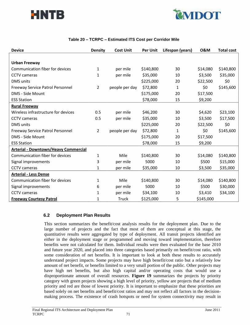
Final Regional ITS Architecture and Deployment Plan June 2011
TCRPC 71
Table 20 – TCRPC – Estimated ITS Cost per Corridor Mile
Device Density Cost Unit Per Unit Lifespan (years) O&M Total cost
Urban Freeway Communication fiber for devices 1 per mile $140,800 30 $14,080 $140,800
CCTV cameras 1 per mile $35,000 10 $3,500 $35,000
DMS units
$225,000 20 $22,500 $0
Freeway Service Patrol Personnel 2 people per day $72,800 1 $0 $145,600
DMS - Side Mount
$175,000 20 $17,500 ESS Station
$78,000 15 $9,200
Rural Freeway Wireless infrastructure for devices 0.5 per mile $46,200 30 $4,620 $23,100
CCTV cameras 0.5 per mile $35,000 10 $3,500 $17,500
DMS units
$225,000 20 $22,500 $0
Freeway Service Patrol Personnel 2 people per day $72,800 1 $0 $145,600
DMS - Side Mount
$175,000 20 $17,500 ESS Station
$78,000 15 $9,200
Arterial - Downtown/Heavy Commercial Communication fiber for devices 1 Mile $140,800 30 $14,080 $140,800
Signal improvements 3 per mile 5000 10 $500 $15,000
CCTV cameras 1 per mile $35,000 10 $3,500 $35,000
Arterial - Less Dense Communication fiber for devices 1 Mile $140,800 30 $14,080 $140,800
Signal improvements 6 per mile 5000 10 $500 $30,000
CCTV cameras 1 per mile $34,100 10 $3,410 $34,100
Freeway Courtesy Patrol 1 Truck $125,000 5 $145,000
6.2 Deployment Plan Results
This section summarizes the benefit/cost analysis results for the deployment plan. Due to the
large number of projects and the fact that most of them are conceptual at this stage, the
quantitative results were aggregated by type of deployment. All transit projects identified are
either in the deployment stage or programmed and moving toward implementation, therefore
benefits were not calculated for them. Individual results were then evaluated for the base 2010
and future year 2020, and placed into three categories based primarily on benefit/cost ratio, with
some consideration of net benefits. It is important to look at both these results to accurately
understand project impacts. Some projects may have high benefit/cost ratio but a relatively low
amount of net benefit, or benefits limited to a very small portion of the public. Other projects may
have high net benefits, but also high capital and/or operating costs that would use a
disproportionate amount of overall resources. Figure 19 summarizes the projects by priority
category with green projects showing a high level of priority, yellow are projects that of medium
priority and red are those of lowest priority. It is important to emphasize that these priorities are
based solely on net benefits and benefit/cost ratios and may not reflect all factors in the decision-
making process. The existence of crash hotspots or need for system connectivity may result in
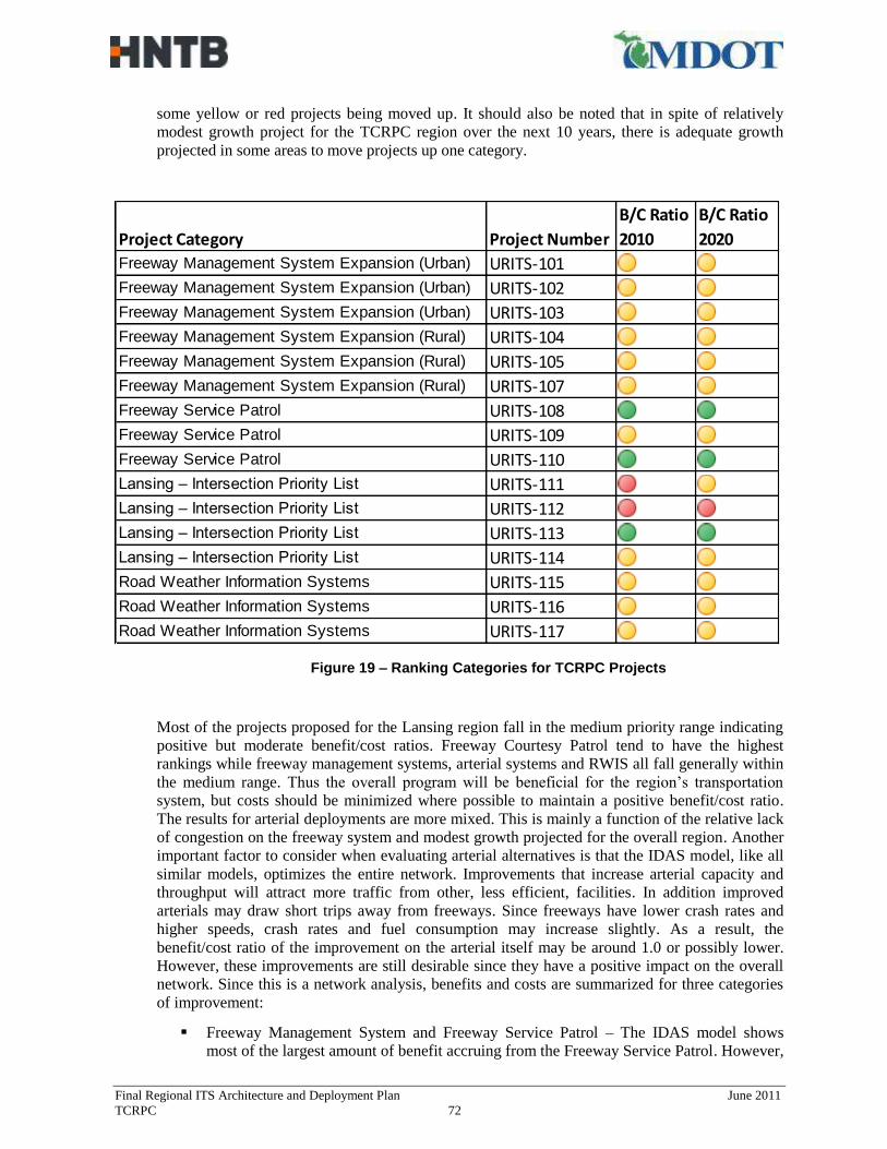
Final Regional ITS Architecture and Deployment Plan June 2011
TCRPC 72
some yellow or red projects being moved up. It should also be noted that in spite of relatively
modest growth project for the TCRPC region over the next 10 years, there is adequate growth
projected in some areas to move projects up one category.
Project Category Project Number
B/C Ratio
2010
B/C Ratio
2020
Freeway Management System Expansion (Urban) URITS-101 2.6 2.7
Freeway Management System Expansion (Urban) URITS-102 1.2 1.3
Freeway Management System Expansion (Urban) URITS-103 3.5 3.9
Freeway Management System Expansion (Rural) URITS-104 3.1 3.2
Freeway Management System Expansion (Rural) URITS-105 2.6 2.7
Freeway Management System Expansion (Rural) URITS-107 3.4 3.7
Freeway Service Patrol URITS-108 9.9 11.5
Freeway Service Patrol URITS-109 3.2 3.7
Freeway Service Patrol URITS-110 7.2 8.0
Lansing – Intersection Priority List URITS-111 0.2 3.7
Lansing – Intersection Priority List URITS-112 0.1 0.2
Lansing – Intersection Priority List URITS-113 11.5 11.5
Lansing – Intersection Priority List URITS-114 3.7 3.7
Road Weather Information Systems URITS-115 2.4 2.2
Road Weather Information Systems URITS-116 2.1 2.1
Road Weather Information Systems URITS-117 3.1 4.0
Figure 19 – Ranking Categories for TCRPC Projects
Most of the projects proposed for the Lansing region fall in the medium priority range indicating
positive but moderate benefit/cost ratios. Freeway Courtesy Patrol tend to have the highest
rankings while freeway management systems, arterial systems and RWIS all fall generally within
the medium range. Thus the overall program will be beneficial for the region’s transportation
system, but costs should be minimized where possible to maintain a positive benefit/cost ratio.
The results for arterial deployments are more mixed. This is mainly a function of the relative lack
of congestion on the freeway system and modest growth projected for the overall region. Another
important factor to consider when evaluating arterial alternatives is that the IDAS model, like all
similar models, optimizes the entire network. Improvements that increase arterial capacity and
throughput will attract more traffic from other, less efficient, facilities. In addition improved
arterials may draw short trips away from freeways. Since freeways have lower crash rates and
higher speeds, crash rates and fuel consumption may increase slightly. As a result, the
benefit/cost ratio of the improvement on the arterial itself may be around 1.0 or possibly lower.
However, these improvements are still desirable since they have a positive impact on the overall
network. Since this is a network analysis, benefits and costs are summarized for three categories
of improvement:
Freeway Management System and Freeway Service Patrol – The IDAS model shows
most of the largest amount of benefit accruing from the Freeway Service Patrol. However,
Final Regional ITS Architecture and Deployment Plan June 2011
TCRPC 73
the FSP cannot work effectively without detection, surveillance and traveler information
systems, supported by the Traffic Management Center, that locate incidents and let the
traveling public know about them. Therefore the most realistic summary combines both
when looking at benefits.
Road Weather Information Systems
Arterial Improvement Systems – As discussed above, the model can show negative
impacts for arterial projects in the area of safety and fuel consumption. This was not the
case in the Lansing analysis although benefits in these areas were minimal.
Table 21 through Table 28 show the benefits and costs by project grouping with urban freeway
and freeway courtesy patrol combined for 2010 and 2020. The highest levels of net benefit and
benefit/cost ratio are realized for the Urban Freeway Management and Freeway Courtesy Patrols
option although all the categories show a positive benefit. Travel time savings constitute by far
the majority of the benefits. Total benefits for the Urban Freeway Management System and
Freeway Courtesy Patrol are projected to increase by over 15% during the 10-year forecast
period, but due to low projected growth rates increases in the other categories are somewhat
lower. Future success of TCRPC’s land use initiative would result in a lower level of benefit for
the freeway alternatives. If future growth is concentrated more in the urban portions of the region,
the arterial and transit ITS alternatives would gain a greater share of the benefits.
In looking at the costs for the TCRPC plan it is important to note that the freeway management
system elements will be operated by the MDOT Statewide Traffic Operations Center (STOC)
while the arterial system will be operated by the City of Lansing. Approximately 80% of the
operating cost estimated for this program ($1.3 million out of $1.5 million) would be allocated to
the rural and urban freeway management systems and the freeway courtesy patrol. Since the full
scope of the STOC is still in development it is not clear what resources would be allocated to
Lansing as opposed to other systems across the State. It is likely that economies of scale can be
gained as new systems are brought on line in the STOC. Therefore estimation of O&M costs is
difficult.
Table 21 – Year 2010 – Urban Freeway Management System and Freeway Courtesy Patrol Benefit/Cost
Summary
Benefits and Costs Monetary Values
Travel Time Savings $9,493,207
Crash Reduction $166,314
Operating Costs $698,106
Environmental $142,993
Total Annual Benefits $10,500,620
Annualized Cost $1,847,713
Net Benefits $8,652,907
Benefit/Cost Ratio 5.7
Capital Cost $8,903,839
Annual O & M Cost $1,018,956
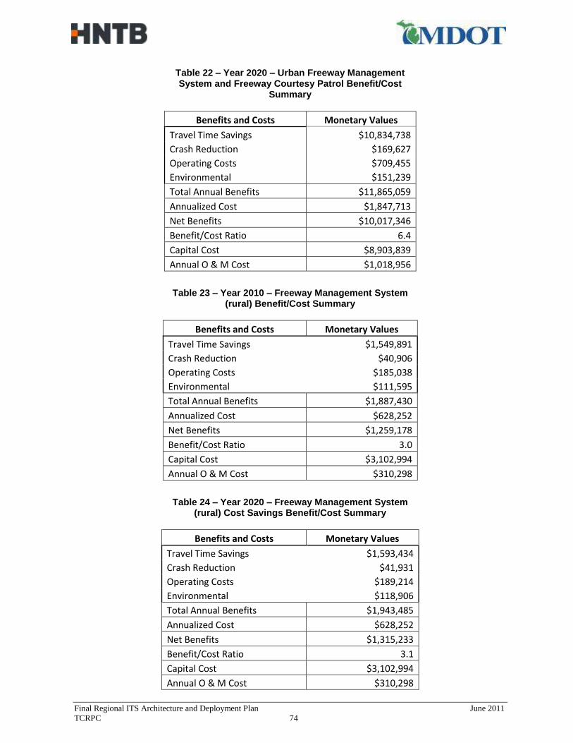
Final Regional ITS Architecture and Deployment Plan June 2011
TCRPC 74
Table 22 – Year 2020 – Urban Freeway Management System and Freeway Courtesy Patrol Benefit/Cost
Summary
Benefits and Costs Monetary Values
Travel Time Savings $10,834,738
Crash Reduction $169,627
Operating Costs $709,455
Environmental $151,239
Total Annual Benefits $11,865,059
Annualized Cost $1,847,713
Net Benefits $10,017,346
Benefit/Cost Ratio 6.4
Capital Cost $8,903,839
Annual O & M Cost $1,018,956
Table 23 – Year 2010 – Freeway Management System (rural) Benefit/Cost Summary
Benefits and Costs Monetary Values
Travel Time Savings $1,549,891
Crash Reduction $40,906
Operating Costs $185,038
Environmental $111,595
Total Annual Benefits $1,887,430
Annualized Cost $628,252
Net Benefits $1,259,178
Benefit/Cost Ratio 3.0
Capital Cost $3,102,994
Annual O & M Cost $310,298
Table 24 – Year 2020 – Freeway Management System (rural) Cost Savings Benefit/Cost Summary
Benefits and Costs Monetary Values
Travel Time Savings $1,593,434
Crash Reduction $41,931
Operating Costs $189,214
Environmental $118,906
Total Annual Benefits $1,943,485
Annualized Cost $628,252
Net Benefits $1,315,233
Benefit/Cost Ratio 3.1
Capital Cost $3,102,994
Annual O & M Cost $310,298
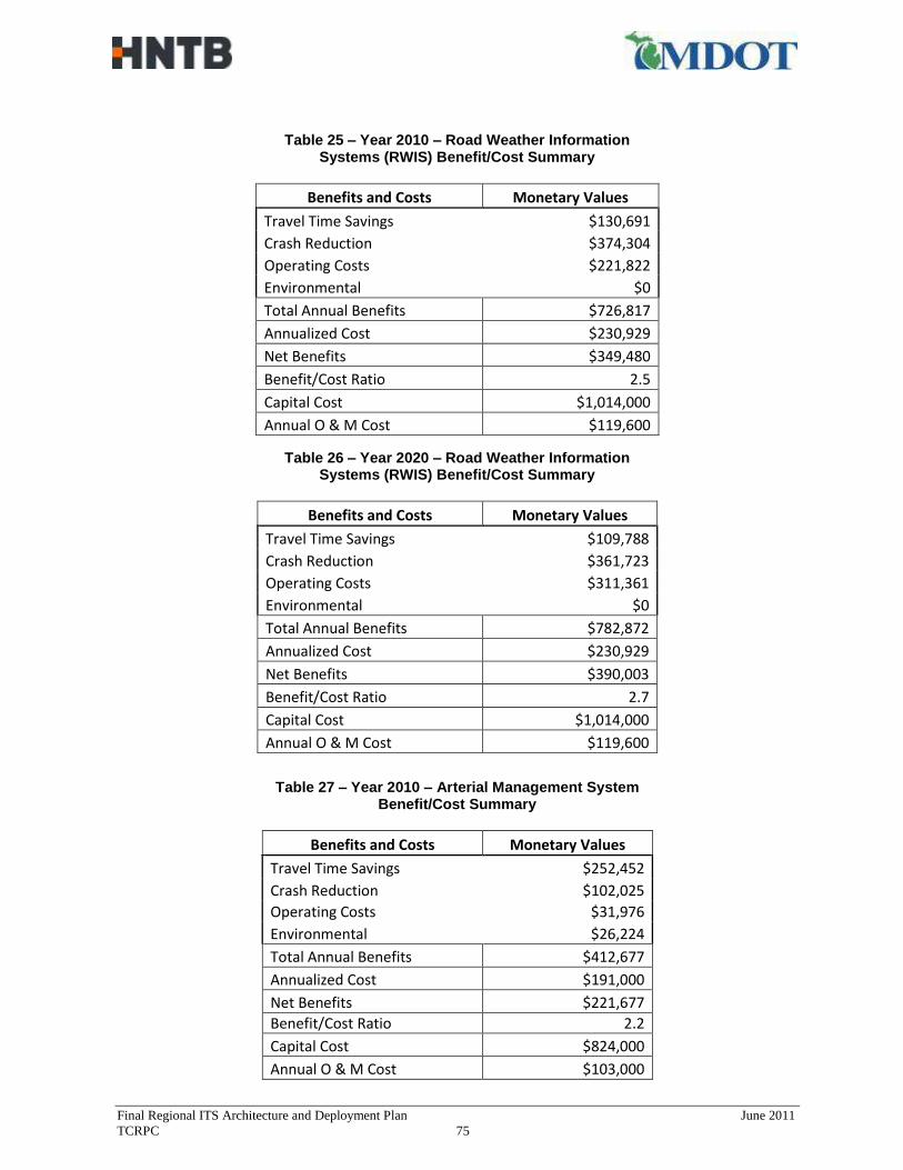
Final Regional ITS Architecture and Deployment Plan June 2011
TCRPC 75
Table 25 – Year 2010 – Road Weather Information Systems (RWIS) Benefit/Cost Summary
Benefits and Costs Monetary Values
Travel Time Savings $130,691
Crash Reduction $374,304
Operating Costs $221,822
Environmental $0
Total Annual Benefits $726,817
Annualized Cost $230,929
Net Benefits $349,480
Benefit/Cost Ratio 2.5
Capital Cost $1,014,000
Annual O & M Cost $119,600
Table 26 – Year 2020 – Road Weather Information Systems (RWIS) Benefit/Cost Summary
Benefits and Costs Monetary Values
Travel Time Savings $109,788
Crash Reduction $361,723
Operating Costs $311,361
Environmental $0
Total Annual Benefits $782,872
Annualized Cost $230,929
Net Benefits $390,003
Benefit/Cost Ratio 2.7
Capital Cost $1,014,000
Annual O & M Cost $119,600
Table 27 – Year 2010 – Arterial Management System Benefit/Cost Summary
Benefits and Costs Monetary Values
Travel Time Savings $252,452
Crash Reduction $102,025
Operating Costs $31,976
Environmental $26,224
Total Annual Benefits $412,677
Annualized Cost $191,000
Net Benefits $221,677
Benefit/Cost Ratio 2.2
Capital Cost $824,000
Annual O & M Cost $103,000
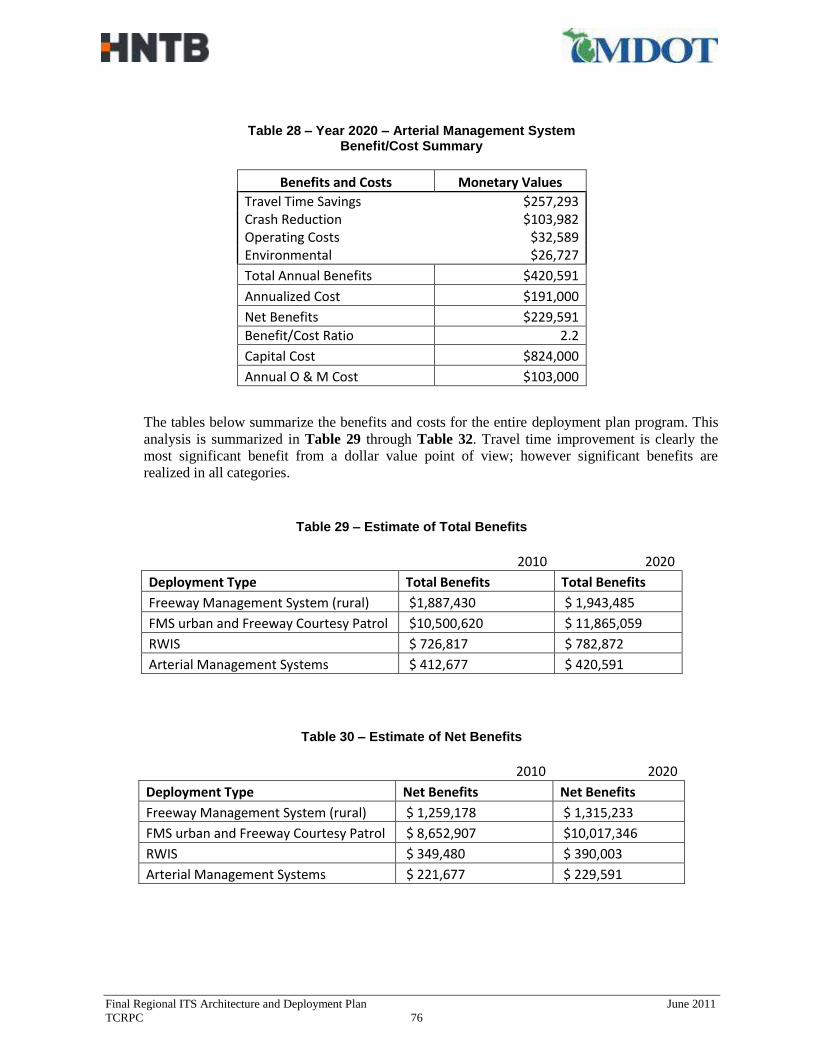
Final Regional ITS Architecture and Deployment Plan June 2011
TCRPC 76
Table 28 – Year 2020 – Arterial Management System Benefit/Cost Summary
Benefits and Costs Monetary Values
Travel Time Savings $257,293 Crash Reduction $103,982 Operating Costs $32,589 Environmental $26,727
Total Annual Benefits $420,591
Annualized Cost $191,000
Net Benefits $229,591
Benefit/Cost Ratio 2.2
Capital Cost $824,000
Annual O & M Cost $103,000
The tables below summarize the benefits and costs for the entire deployment plan program. This
analysis is summarized in Table 29 through Table 32. Travel time improvement is clearly the
most significant benefit from a dollar value point of view; however significant benefits are
realized in all categories.
Table 29 – Estimate of Total Benefits
2010 2020
Deployment Type Total Benefits Total Benefits
Freeway Management System (rural) $1,887,430 $ 1,943,485
FMS urban and Freeway Courtesy Patrol $10,500,620 $ 11,865,059
RWIS $ 726,817 $ 782,872
Arterial Management Systems $ 412,677 $ 420,591
Table 30 – Estimate of Net Benefits
2010 2020
Deployment Type Net Benefits Net Benefits
Freeway Management System (rural) $ 1,259,178 $ 1,315,233
FMS urban and Freeway Courtesy Patrol $ 8,652,907 $10,017,346
RWIS $ 349,480 $ 390,003
Arterial Management Systems $ 221,677 $ 229,591
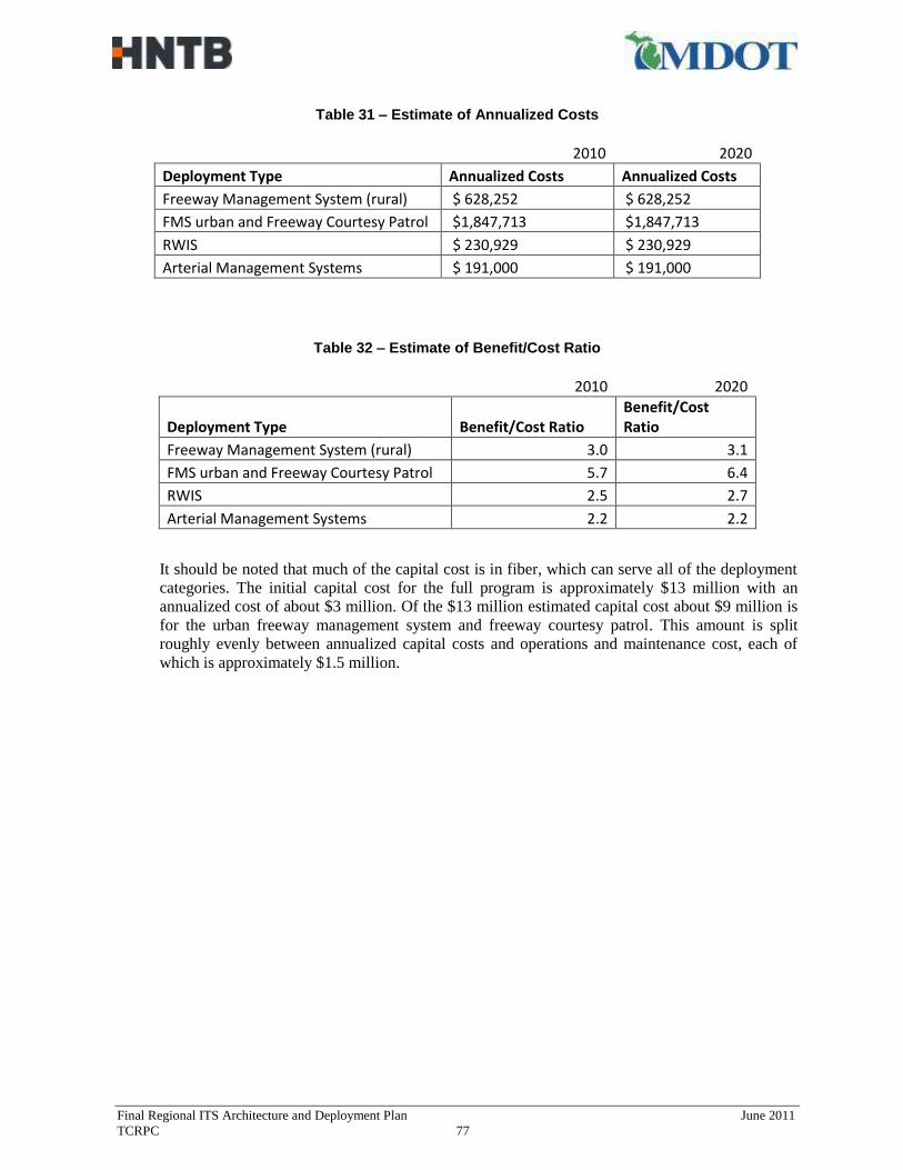
Final Regional ITS Architecture and Deployment Plan June 2011
TCRPC 77
Table 31 – Estimate of Annualized Costs
2010 2020
Deployment Type Annualized Costs Annualized Costs
Freeway Management System (rural) $ 628,252 $ 628,252
FMS urban and Freeway Courtesy Patrol $1,847,713 $1,847,713
RWIS $ 230,929 $ 230,929
Arterial Management Systems $ 191,000 $ 191,000
Table 32 – Estimate of Benefit/Cost Ratio
2010 2020
Deployment Type Benefit/Cost Ratio Benefit/Cost Ratio
Freeway Management System (rural) 3.0 3.1
FMS urban and Freeway Courtesy Patrol 5.7 6.4
RWIS 2.5 2.7
Arterial Management Systems 2.2 2.2
It should be noted that much of the capital cost is in fiber, which can serve all of the deployment
categories. The initial capital cost for the full program is approximately $13 million with an
annualized cost of about $3 million. Of the $13 million estimated capital cost about $9 million is
for the urban freeway management system and freeway courtesy patrol. This amount is split
roughly evenly between annualized capital costs and operations and maintenance cost, each of
which is approximately $1.5 million.