Embed Size (px)
Citation preview
H250 /M40H250 /M40H250 /M40H250 /M40 Technical DatasheetTechnical DatasheetTechnical DatasheetTechnical Datasheet
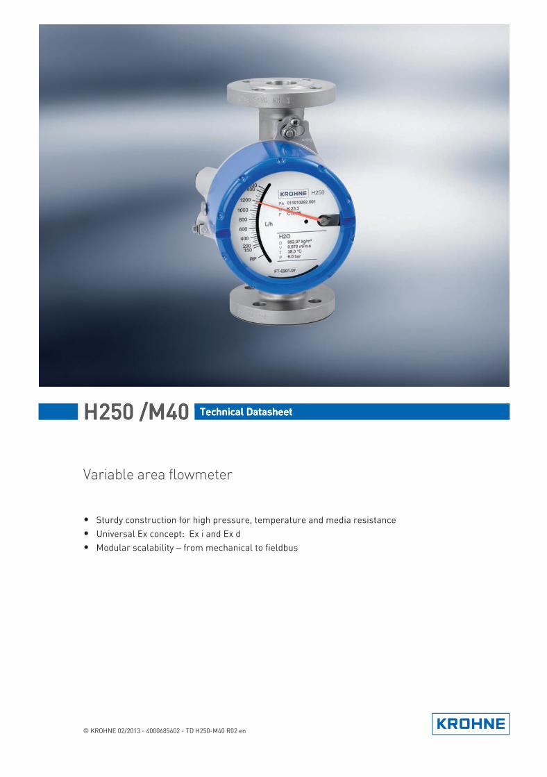
Variable area flowmeter
• Sturdy construction for high pressure, temperature and media resistance• Universal Ex concept: Ex i and Ex d• Modular scalability – from mechanical to fieldbus
© KROHNE 02/2013 - 4000685602 - TD H250-M40 R02 en
TD_H250_M40_R02_en_685602_PRT.book Page 1 Wednesday, February 6, 2013 10:55 AM
CONTENTS
2 www.krohne.com 02/2013 - 4000685602 - TD H250-M40 R02 en
H250 /M40
1 Product features 3
1.1 The standard solution for the process industry............................................................... 31.2 Options and variants......................................................................................................... 51.3 Functional principle.......................................................................................................... 7
2 Technical data 8
2.1 Technical data................................................................................................................... 82.2 Dimensions and weights ................................................................................................ 142.3 Measuring ranges........................................................................................................... 17
3 Installation 25
3.1 Intended use ................................................................................................................... 253.2 Installation conditions .................................................................................................... 26
3.2.1 Tightening torques................................................................................................................ 283.2.2 Magnetic filters ..................................................................................................................... 283.2.3 Heat insulation ...................................................................................................................... 293.2.4 Float damping ....................................................................................................................... 303.2.5 Pointer damping.................................................................................................................... 30
4 Electrical connections 31
4.1 Security information....................................................................................................... 314.2 Electrical connection indicator M40............................................................................... 31
4.2.1 Indicator M40 - limit switches .............................................................................................. 314.2.2 Current output ESK4............................................................................................................. 344.2.3 Binary inputs/outputs ESK4-T .............................................................................................. 374.2.4 ESK4-T pulse output ............................................................................................................. 404.2.5 ESK4-T Reset input............................................................................................................... 41
4.3 Grounding connections................................................................................................... 414.4 Protection category ........................................................................................................ 41
5 Order form 43
TD_H250_M40_R02_en_685602_PRT.book Page 2 Wednesday, February 6, 2013 10:55 AM
PRODUCT FEATURES 1
3
H250 /M40
www.krohne.com02/2013 - 4000685602 - TD H250-M40 R02 en
Product features
1.1 The standard solution for the process industry
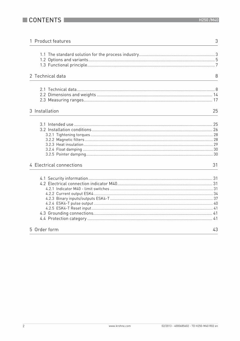
The all-metal variable area flowmeter H250 is used for flow measurement of conductive and non-conductive liquids, gases and vapours.
1 Limit switch2 4...20 mA output3 With LCD, flow counter, electronic limit switches and pulse output4 Fieldbus - Profibus PA or Foundation Fieldbus
TD_H250_M40_R02_en_685602_PRT.book Page 3 Wednesday, February 6, 2013 10:55 AM

1 PRODUCT FEATURES
4
H250 /M40
www.krohne.com 02/2013 - 4000685602 - TD H250-M40 R02 en
Highlights• Simple, low-cost installation: Measure and display without auxiliary power supply• Universal Ex concept: Ex i and Ex d• Modular scalability – from mechanical to fieldbus• Any installation position: vertical upward, horizontal, vertical downward• Robust measuring tube construction for high process temperatures and extreme operating
pressures
• Choice of material: Stainless steel, hastelloy®, titanium, Monel, PTFE/TFM etc.• Many connection variants: flanged, screwed, clamped, weld-on ends etc.• Extended measuring range: up to100:1• High application safety, even with extremely low flows
IndustriesCan be used in all industrial sectors, for example:
• Chemicals• Petrochemicals• Pharmaceuticals• Machinery• Food & Beverage• Oil & Gas• Iron, Steel & Metals• Power plants• Paper & Pulp• Water & Wastewater
Applications• Continuous gas and liquid measurement• Measurement of non-conductive media• Industrial burner controlling• Compressor monitoring• Dry-run protection of pumps
TD_H250_M40_R02_en_685602_PRT.book Page 4 Wednesday, February 6, 2013 10:55 AM

PRODUCT FEATURES 1
5
H250 /M40
www.krohne.com02/2013 - 4000685602 - TD H250-M40 R02 en
1.2 Options and variants
FOOD & PHARMA (H250 F)
PTFE/ceramic liner for aggressive media
The only EHEDG-certified variable area flowmeter approved for used in the food and pharmaceuticals industry.Smooth stainless steel surfaces with a surface roughness of ≤ 0.8 µm or 0,6 µm on parts exposed to the media make it difficult for deposits to take hold and are very easy to clean.Combined with a design featuring no dead spaces or stagnation zones, micro-organisms have no chance to adhere and multiply.The measuring devices can be cleaned (CIP) and sterilised (SIP) in place.Suitable connections and FDA conforming materials for the food and pharmaceutical industry are available.
All wetted parts are made of PTFE or ceramic and can thus be used for almost all acids and alkalis.Depending on the choice of material, the measuring device can be used up to a maximum temperature of 70°C / 158°F (PTFE) or 250°C / 482°F (ceramic).
TD_H250_M40_R02_en_685602_PRT.book Page 5 Wednesday, February 6, 2013 10:55 AM
1 PRODUCT FEATURES
6
H250 /M40
www.krohne.com 02/2013 - 4000685602 - TD H250-M40 R02 en
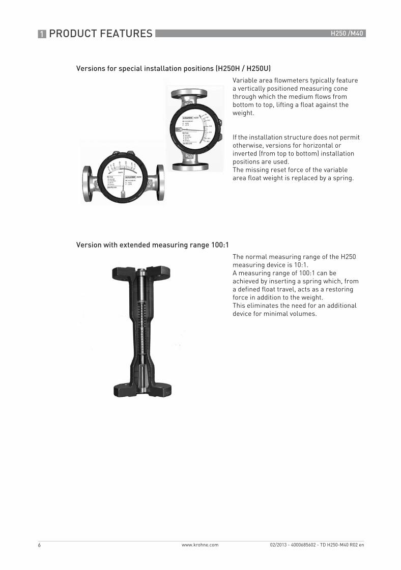
Versions for special installation positions (H250H / H250U)
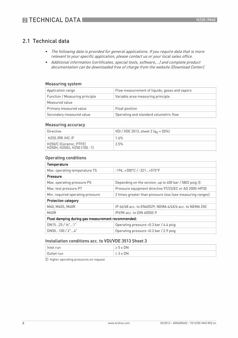
Version with extended measuring range 100:1
Variable area flowmeters typically feature a vertically positioned measuring cone through which the medium flows from bottom to top, lifting a float against the weight.
If the installation structure does not permit otherwise, versions for horizontal or inverted (from top to bottom) installation positions are used.The missing reset force of the variable area float weight is replaced by a spring.
The normal measuring range of the H250 measuring device is 10:1.A measuring range of 100:1 can be achieved by inserting a spring which, from a defined float travel, acts as a restoring force in addition to the weight.This eliminates the need for an additional device for minimal volumes.
TD_H250_M40_R02_en_685602_PRT.book Page 6 Wednesday, February 6, 2013 10:55 AM

PRODUCT FEATURES 1
7
H250 /M40
www.krohne.com02/2013 - 4000685602 - TD H250-M40 R02 en
1.3 Functional principle
The H250 flowmeter operates on the float measuring principle. The measuring unit consists of a metal cone, inside of which a float can move up and down freely. The flow goes from bottom to top. The float changes position so that the lifting force acting on it F1 is in equilibrium with the form drag F2 and its weight F3: F3 = F1 + F2
1 For the indicator, the flow-dependent height of the float in the measuring unit is transmitted by means of a magnetic coupling and displayed on a scale.
2 For a built-in signal converter (ESK4), the flow-dependent height of the float in the measuring unit is detected by the S1 and S2 magnetic field sensors and electronically processed.
The flowmeter operates based on a modified float measuring principle. The guided float adjusts itself so that the flow force acting on it is in equilibrium with the opposing spring force. The flow-dependent position of the float in the measuring unit is displayed on a scale by means of a magnetic coupling.
1 Indication principle M40 magnetic coupling2 Magnetic coupling sensors
Operating principle of H250H and H250U
Figure 1-1: Operating principle H250H and H250U
1 H250H - horizontal flow direction2 H250U - flow direction from top to bottom
TD_H250_M40_R02_en_685602_PRT.book Page 7 Wednesday, February 6, 2013 10:55 AM
2 TECHNICAL DATA
8
H250 /M40
www.krohne.com 02/2013 - 4000685602 - TD H250-M40 R02 en
Technical data
2.1 Technical data
• The following data is provided for general applications. If you require data that is more relevant to your specific application, please contact us or your local sales office.
• Additional information (certificates, special tools, software,...) and complete product documentation can be downloaded free of charge from the website (Download Center).
Measuring systemApplication range Flow measurement of liquids, gases and vapors
Function / Measuring principle Variable area measuring principle
Measured value
Primary measured value Float position
Secondary measured value Operating and standard volumetric flow
Measuring accuracyDirective VDI / VDE 3513, sheet 2 (qG = 50%)
H250 /RR /HC /F 1.6%
H250/C (Ceramic, PTFE)H250H, H250U, H250 (100 : 1)
2.5%
Operating conditionsTemperatureTemperatureTemperatureTemperature
Max. operating temperature TS -196..+300°C / -321...+572°F
PressurePressurePressurePressure
Max. operating pressure PS Depending on the version, up to 400 bar / 5802 psig 1
Max. test pressure PT Pressure equipment directive 97/23/EC or AD 2000-HP30
Min. required operating pressure 2 times greater than pressure loss (see measuring ranges)
Protection categoryProtection categoryProtection categoryProtection category
M40, M40S, M40R IP 66/68 acc. to EN60529, NEMA 4/4X/6 acc. to NEMA 250
M40R IP69K acc. to DIN 40050-9
Float damping during gas measurement recommended:Float damping during gas measurement recommended:Float damping during gas measurement recommended:Float damping during gas measurement recommended:
DN15...25 / ½"...1" Operating pressure <0.3 bar / 4.4 psig
DN50...100 / 2"...4" Operating pressure <0.2 bar / 2.9 psig
Installation conditions acc. to VDI/VDE 3513 Sheet 3Inlet run ≥ 5 x DN
Outlet run ≥ 3 x DN
1 higher operating pressures on request
TD_H250_M40_R02_en_685602_PRT.book Page 8 Wednesday, February 6, 2013 10:55 AM
TECHNICAL DATA 2
9
H250 /M40
www.krohne.com02/2013 - 4000685602 - TD H250-M40 R02 en
Materials
Other options:• Special materials on request: e.g. SMO 254, titanium, 1.4435• Float damping: ceramic or PEEK• Gasket for devices with female thread as insert: O-ring FPM / FKM
TemperaturesTemperaturesTemperaturesTemperaturesFor devices to be used in hazardous areas, special temperature ranges apply. These can be found in the separate instructions
Temperatures H250/M40 - mechanical indicator without power supply
Ambient temperatures Tamb. with electrical components
Item Flange / raised face Measuring tube
Float Float stop / guide
Ring orifice
H250/RRstainless steel
CrNi steel 1.4404 massive 1
CrNi steel 1.4404 1 -
H250/HCHastelloy®
CrNi steel 1.4571 with plated Hastelloy® C4 (2.4610) 1
Hastelloy® C-22 (2.4602) -
H250/CCeramics/PTFE 2
CrNi-Stahl 1.4571with TFM/PTFE liner 3
PTFE or Al2O3 with FFKM gasket
Al2O3and PTFE
Al2O3
H250/F - Food CrNi-Stahl 1.4435 -
1 CrNi steel 1.4571 on request, for clamp connection CrNi steel 1.44352 DN100/4" only PTFE3 TFM/PTFE liner (electrically non-conductive)
Material Product temperature Ambient temperature
Float Liner [°C] [°F] [°C] [°F]
H250/RR stainless steel -196...+300 -321...+572 -40...+120 -40…+248
H250/RR screw fitting -196...+300 -321...+572 -20…+120 -4…+248
H250/HC Hastelloy® C4 -196...+300 -321...+572 -40...+120 -40…+248
H250/C PTFE -196...+70 -321...+158 -40...+70 -40…+158
H250/C Ceramic PTFE -196...+150 -321...+302 -40...+70 -40…+158
H250/C Ceramic TFM / Ceramic -196...+250 -321...+482 -40...+120 -40…+248
H250 H/U Spring material Stainless Steel 316
-40...+100 -40…+212 -40…+120 -40…+248
Spring material Hastelloy -40...+200 -40...+392 -40…+120 -40…+248
Version [°C] [°F]
ESK4, ESK4-FF, ESK4-PA -40...+70 -40...+158
ESK4-T 1 -40...+70 -40...+158
Limit switches SJ3,5-SN / I7S23,5-N / Reed SPST -40...+70 -40...+158
Limit switches SC3,5-N0 / SJ3,5-S1N / SB3,5-E2 -25...+70 -13...+158
1 Display contrast out of the temperature range 0...60 °C / 32..140°F decreasing.
TD_H250_M40_R02_en_685602_PRT.book Page 9 Wednesday, February 6, 2013 10:55 AM
2 TECHNICAL DATA
10
H250 /M40
www.krohne.com 02/2013 - 4000685602 - TD H250-M40 R02 en
Temperatures H250/M40 - with electrical components [°C]
Maximum product temperatures H250/M40 - with electrical components [°F]
1 if there are no heat insulation measures, a heat-resistant cable is necessary (continuous operating temperature of the cable to be used: +100°C)
Abbreviation
Tamb. < +40 °C Tamb. < +60 °C
EN ASME Version with Standard HT Standard HT
DN15, DN25
½", 1" ESK4, ESK4-FF, ESK4-PA +200 +300 +180 +300
ESK4-T +200 +300 +80 +130
Limit switch NAMUR +200 +300 +200 +300
3-wire limit switch +200 +300 +130 +295
DN50 2“ ESK4, ESK4-FF, ESK4-PA +200 +300 +165 +300
ESK4-T +180 +300 +75 +100
Limit switch NAMUR +200 +300 +200 +300
3-wire limit switch +200 +300 +120 +195
DN80, DN100
3“, 4" ESK4, ESK4-FF, ESK4-PA +200 +300 +150 +250
ESK4-T +150 +270 +70 +85
Limit switch NAMUR +200 +300 +200 +300
3-wire limit switch +190 +300 +110 +160
Tamb. < +104 °F Tamb. < +140 °F 1
EN ASME Version with Standard HT Standard HT
DN15, DN25
½", 1" ESK4, ESK4-FF, ESK4-PA 392 572 356 572
ESK4-T 392 572 176 266
Limit switch NAMUR 392 572 392 572
3-wire limit switch 392 572 266 563
DN 50 2“ ESK4, ESK4-FF, ESK4-PA 392 572 165 572
ESK4-T 356 572 167 212
Limit switch NAMUR 392 572 392 572
3-wire limit switch 392 572 248 383
DN 80, DN100
3“, 4" ESK4, ESK4-FF, ESK4-PA 392 572 302 482
ESK4-T 302 518 158 185
Limit switch NAMUR 392 572 392 572
3-wire limit switch 374 572 230 320
HT High-Temperature version
ESK4 Current output 2-wire 4…20 mA
ESK4-T ESK4 with LCD, binary status outputs, digital counter and pulse output.
ESK4-FF FOUNDATION FIELDBUS interface
ESK4-PA PROFIBUS PA interface
TD_H250_M40_R02_en_685602_PRT.book Page 10 Wednesday, February 6, 2013 10:55 AM
TECHNICAL DATA 2
11
H250 /M40
www.krohne.com02/2013 - 4000685602 - TD H250-M40 R02 en
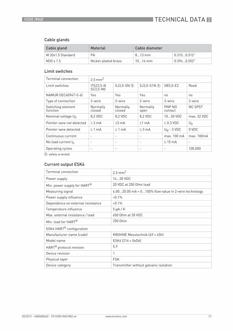
Cable glands
Limit switches
Current output ESK4
Cable gland Material Cable diameter
M 20x1.5 Standard PA 8...13 mm 0.315...0.512"
M20 x 1.5 Nickel-plated brass 10...14 mm 0.394...0.552"
Terminal connection 2.5 mm2
Limit switches I7S23,5-NSC3,5-N0
SJ3,5-SN 1 SJ3,5-S1N 1 SB3,5-E2 Reed
NAMUR (IEC60947-5-6) Yes Yes Yes no no
Type of connection 2-wire 2-wire 2-wire 3-wire 2-wire
Switching element function
Normally closed
Normally closed
Normally open
PNP NO contact
NC SPST
Nominal voltage U0 8,2 VDC 8,2 VDC 8,2 VDC 10...30 VDC max. 32 VDC
Pointer vane not detected ≥ 3 mA ≥3 mA ≤1 mA ≤ 0.3 VDC U0
Pointer vane detected ≤ 1 mA ≤ 1 mA ≥ 3 mA UB - 3 VDC 0 VDC
Continuous current - - - max. 100 mA max. 100mA
No load current I0 - - - ≤ 15 mA -
Operating cycles - - - - 100.000
1 safety oriented
Terminal connection 2.5 mm2
Power supply 14...30 VDC
Min. power supply for HART® 20 VDC at 250 Ohm load
Measuring signal 4.00...20.00 mA = 0...100% flow value in 2-wire technology
Power supply influence <0.1%
Dependence on external resistance <0.1%
Temperature influence 5 µA / K
Max. external resistance / load 650 Ohm at 30 VDC
Min. load for HART® 250 Ohm
ESK4 HART® configuration
Manufacturer name (code) KROHNE Messtechnik (69 = 45h)
Model name ESK4 (214 = 0xD6)
HART® protocol revision 5.9
Device revision 1
Physical layer FSK
Device category Transmitter without galvanic isolation
TD_H250_M40_R02_en_685602_PRT.book Page 11 Wednesday, February 6, 2013 10:55 AM
2 TECHNICAL DATA
12
H250 /M40
www.krohne.com 02/2013 - 4000685602 - TD H250-M40 R02 en
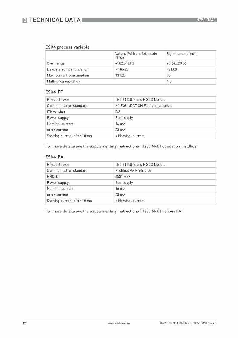
ESK4-FF
For more details see the supplementary instructions "H250 M40 Foundation Fieldbus"
ESK4-PA
For more details see the supplementary instructions "H250 M40 Profibus PA"
ESK4 process variableValues [%] from full-scale range
Signal output [mA]
Over range +102.5 (±1%) 20.24...20.56
Device error identification > 106.25 >21.00
Max. current consumption 131.25 25
Multi-drop operation 4.5
Physical layer IEC 61158-2 and FISCO Modell
Communication standard H1 FOUNDATION Fieldbus protokol
ITK version 5.2
Power supply Bus supply
Nominal current 16 mA
error current 23 mA
Starting current after 10 ms < Nominal current
Physical layer IEC 61158-2 and FISCO Modell
Communication standard Profibus PA Profil 3.02
PNO ID 4531 HEX
Power supply Bus supply
Nominal current 16 mA
error current 23 mA
Starting current after 10 ms < Nominal current
TD_H250_M40_R02_en_685602_PRT.book Page 12 Wednesday, February 6, 2013 10:55 AM
TECHNICAL DATA 2
13
H250 /M40
www.krohne.com02/2013 - 4000685602 - TD H250-M40 R02 en
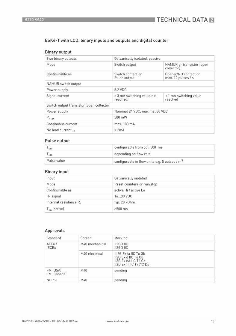
ESK4-T with LCD, binary inputs and outputs and digital counter
Approvals
Binary outputTwo binary outputs Galvanically isolated, passive
Mode Switch output NAMUR or transistor (open collector)
Configurable as Switch contact or Pulse output
Opener/NO contact ormax. 10 pulses / s
NAMUR switch output
Power supply 8,2 VDC
Signal current > 3 mA switching value not reached;
< 1 mA switching value reached
Switch output transistor (open collector)
Power supply Nominal 24 VDC, maximal 30 VDC
Pmax 500 mW
Continuous current max. 100 mA
No load current I0 ≤ 2mA
Pulse outputTon configurable from 50...500 ms
Toff depending on flow rate
Pulse value configurable in flow units e.g. 5 pulses / m3
Binary inputInput Galvanically isolated
Mode Reset counters or run/stop
Configurable as active Hi / active Lo
H- signal 16...30 VDC
Internal resistance Ri typ. 20 kOhm
Ton (active) ≥500 ms
Standard Screen Marking
ATEX /IECEx
M40 mechanical II2GD IICII3GD IIC
M40 electrical III2G Ex ia IIC T6 GbII2G Ex d IIC T6 GbII3G Ex nA IIC T6 GcII2D Ex t IIIC T70°C Db
FM (USA)FM (Canada)
M40 pending
NEPSI M40 pending
TD_H250_M40_R02_en_685602_PRT.book Page 13 Wednesday, February 6, 2013 10:55 AM

2 TECHNICAL DATA
14
H250 /M40
www.krohne.com 02/2013 - 4000685602 - TD H250-M40 R02 en
2.2 Dimensions and weights
Dimensions H250/M40
Front view Side view with heating High temperature
a b d h
[mm] ["] [mm] ["] [mm] ["] [mm] ["]
All nominal sizes 138 5.44 250 9.85 160 6.30 150 5.91
ISO 228 300 11.82
H250/C - 3"/300 lb 300 11.82
EN ASME c e Ø f g j
[mm] ["] [mm] ["] [mm] ["] [mm] ["] [mm] ["]
DN15 ½" 94 3.70 114 4.49 20 0.79 100 3.94 197 7.76
DN25 1" 94 3.70 125 4.92 32 1.26 106 4.18 208 8.19
DN50 2" 107 4.22 139 5.48 65 2.56 120 4.73 222 8.75
DN80 3" 107 4.22 155 6.11 89 3.51 145 5.71 238 9.38
DN100 4" 107 4.22 164 6.46 114 4.49 150 5.91 247 9.73
ISO 228Female thread
screwed
ISO 228Female thread
welded
H250/FClamp connection
1
H250/FScrew connection
DIN 11851
1 Stainless steel 1.4435 - EHEDG tested - wetted surfaces Ra ≤ 0.8 / 0.6 µm
TD_H250_M40_R02_en_685602_PRT.book Page 14 Wednesday, February 6, 2013 10:55 AM

TECHNICAL DATA 2
15
H250 /M40
www.krohne.com02/2013 - 4000685602 - TD H250-M40 R02 en
WeightsWeightsWeightsWeights
Process connectionsProcess connectionsProcess connectionsProcess connections
Higher pressure ratings and other connections on request
H250 with heating
Nominal meter size EN 1092-1 Flange connection Ermeto connection
EN ASME [kg] [lb] [kg] [lb] [kg] [lb]
DN15 ½“ 3.5 7.7 5.6 12.6 3.9 8.6
DN25 1“ 5 11 7.5 16.5 5.8 12.8
DN50 2“ 8.2 18.1 11.2 24.7 9.5 21
DN80 3“ 12.2 26.9 14.8 32.6 13.1 28.9
DN100 4“ 14 30.9 17.4 38.4 15.7 34.6
H250/C [Ceramic / PTFE] Screw connec.
Nominal meter size EN 1092-1 ASME 150 lb ASME 300 lb DIN 11864-1
EN ASME [kg] [lb] [kg] [lb] [kg] [lb] [kg] [lb]
DN15 ½“ 3.5 7.7 3.2 7.1 3.5 7.7 2 4.4
DN25 1“ 5 11 5.2 11.5 6.8 15 3.5 7.7
DN50 2“ 10 22.1 10 22.1 11 24.3 5 11
DN80 3“ 13 28.7 13 28.7 15 33.1 7.6 16.8
DN100 4“ 15 33.1 16 35.3 17 37.5 10.3 22.7
Standard Conn. dim. Pressure rating
Flanges (H250/RR /HC /C) EN 1092-1 DN15...150 PN16...250
ASME B16.5 ½...6" 150...2500 lb
JIS B 2220 15…100 10...20K
Clamp connections (H250/RR /F) DlN 32676 DN15...100 10...16 bar
ISO 2852 Size 25...139.7 10...16 bar
Screw connections (H250/RR /HC /F) DIN 11851 DN15...100 25...40 bar
SMS 1146 1...4" 6 bar / 88.2 psig
Female thread welded (H250/RR /HC) ISO 228 G½...G2" ≥ 50 bar / 735 psig
ASME B1.20.1 ½…2" NPT
Female thread (H250/RR /HC)with insert, FPM gasket and union nut
ISO 228 G½…2" ≤ 50 bar≤ 735 psig
ASME B1.20.1 ½…2" NPT
Thread connection aseptic (H250/F) DIN 11864 - 1 DN15…50 PN40
DN80…100 PN 16
Flange aseptic (H250/F) DIN 11864 - 2 DN15…50 PN40
DN80…DN100 PN 16
Meters (H250/RR /HC) with heating:Meters (H250/RR /HC) with heating:Meters (H250/RR /HC) with heating:Meters (H250/RR /HC) with heating:
Heating with flange connection EN 1092-1 DN15 PN40
ASME B16.5 ½" 150 lb / RF
Heating pipe connection for Ermeto - E12 PN40
TD_H250_M40_R02_en_685602_PRT.book Page 15 Wednesday, February 6, 2013 10:55 AM
2 TECHNICAL DATA
16
H250 /M40
www.krohne.com 02/2013 - 4000685602 - TD H250-M40 R02 en
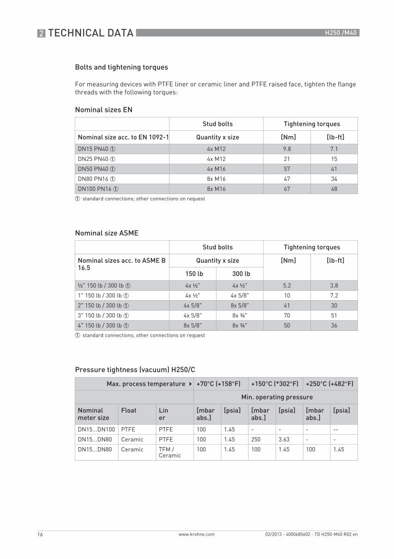
Bolts and tightening torques
For measuring devices with PTFE liner or ceramic liner and PTFE raised face, tighten the flange threads with the following torques:
Nominal sizes EN
Nominal size ASME
Pressure tightness (vacuum) H250/C
Stud bolts Tightening torques
Nominal size acc. to EN 1092-1 Quantity x size [Nm] [lb-ft]
DN15 PN40 1 4x M12 9.8 7.1
DN25 PN40 1 4x M12 21 15
DN50 PN40 1 4x M16 57 41
DN80 PN16 1 8x M16 47 34
DN100 PN16 1 8x M16 67 48
1 standard connections; other connections on request
Stud bolts Tightening torques
Nominal sizes acc. to ASME B 16.5
Quantity x size [Nm] [lb-ft]
150 lb 300 lb
½" 150 lb / 300 lb 1 4x ½" 4x ½" 5.2 3.8
1" 150 lb / 300 lb 1 4x ½" 4x 5/8" 10 7.2
2" 150 lb / 300 lb 1 4x 5/8" 8x 5/8" 41 30
3" 150 lb / 300 lb 1 4x 5/8" 8x ¾" 70 51
4" 150 lb / 300 lb 1 8x 5/8" 8x ¾" 50 36
1 standard connections; other connections on request
Max. process temperature +70°C (+158°F) +150°C (*302°F) +250°C (+482°F)
Min. operating pressure
Nominal meter size
Float Liner
[mbar abs.]
[psia] [mbar abs.]
[psia] [mbar abs.]
[psia]
DN15...DN100 PTFE PTFE 100 1.45 - - - --
DN15...DN80 Ceramic PTFE 100 1.45 250 3.63 - -
DN15...DN80 Ceramic TFM / Ceramic
100 1.45 100 1.45 100 1.45
TD_H250_M40_R02_en_685602_PRT.book Page 16 Wednesday, February 6, 2013 10:55 AM
TECHNICAL DATA 2
17
H250 /M40
www.krohne.com02/2013 - 4000685602 - TD H250-M40 R02 en
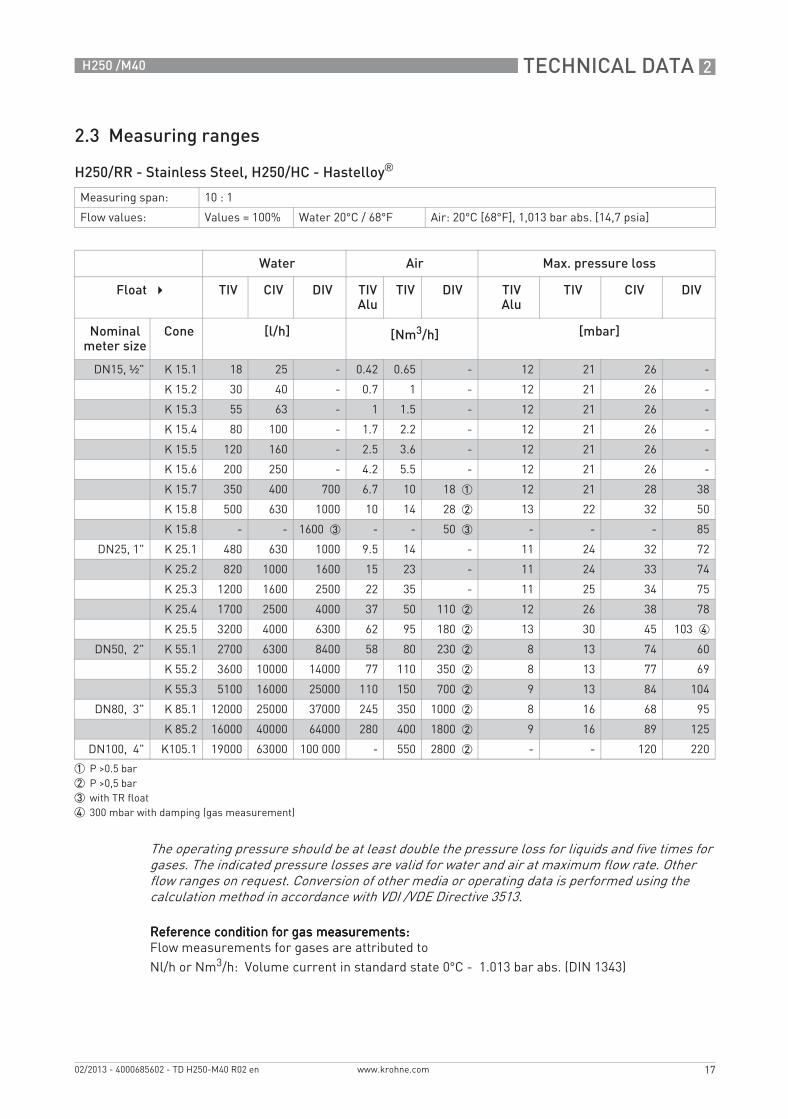
2.3 Measuring ranges
H250/RR - Stainless Steel, H250/HC - Hastelloy®
Reference condition for gas measurements:Reference condition for gas measurements:Reference condition for gas measurements:Reference condition for gas measurements:Flow measurements for gases are attributed toNl/h or Nm3/h: Volume current in standard state 0°C - 1.013 bar abs. (DIN 1343)
Measuring span: 10 : 1
Flow values: Values = 100% Water 20°C / 68°F Air: 20°C [68°F], 1,013 bar abs. [14,7 psia]
Water Air Max. pressure loss
Float TIV CIV DIV TIVAlu
TIV DIV TIVAlu
TIV CIV DIV
Nominal meter size
Cone [l/h] [Nm3/h] [mbar]
DN15, ½" K 15.1 18 25 - 0.42 0.65 - 12 21 26 -
K 15.2 30 40 - 0.7 1 - 12 21 26 -
K 15.3 55 63 - 1 1.5 - 12 21 26 -
K 15.4 80 100 - 1.7 2.2 - 12 21 26 -
K 15.5 120 160 - 2.5 3.6 - 12 21 26 -
K 15.6 200 250 - 4.2 5.5 - 12 21 26 -
K 15.7 350 400 700 6.7 10 18 1 12 21 28 38
K 15.8 500 630 1000 10 14 28 2 13 22 32 50
K 15.8 - - 1600 3 - - 50 3 - - - 85
DN25, 1" K 25.1 480 630 1000 9.5 14 - 11 24 32 72
K 25.2 820 1000 1600 15 23 - 11 24 33 74
K 25.3 1200 1600 2500 22 35 - 11 25 34 75
K 25.4 1700 2500 4000 37 50 110 2 12 26 38 78
K 25.5 3200 4000 6300 62 95 180 2 13 30 45 103 4
DN50, 2" K 55.1 2700 6300 8400 58 80 230 2 8 13 74 60
K 55.2 3600 10000 14000 77 110 350 2 8 13 77 69
K 55.3 5100 16000 25000 110 150 700 2 9 13 84 104
DN80, 3" K 85.1 12000 25000 37000 245 350 1000 2 8 16 68 95
K 85.2 16000 40000 64000 280 400 1800 2 9 16 89 125
DN100, 4" K105.1 19000 63000 100 000 - 550 2800 2 - - 120 220
1 P >0.5 bar2 P >0,5 bar3 with TR float4 300 mbar with damping (gas measurement)
The operating pressure should be at least double the pressure loss for liquids and five times for gases. The indicated pressure losses are valid for water and air at maximum flow rate. Other flow ranges on request. Conversion of other media or operating data is performed using the calculation method in accordance with VDI /VDE Directive 3513.
TD_H250_M40_R02_en_685602_PRT.book Page 17 Wednesday, February 6, 2013 10:55 AM
2 TECHNICAL DATA
18
H250 /M40
www.krohne.com 02/2013 - 4000685602 - TD H250-M40 R02 en
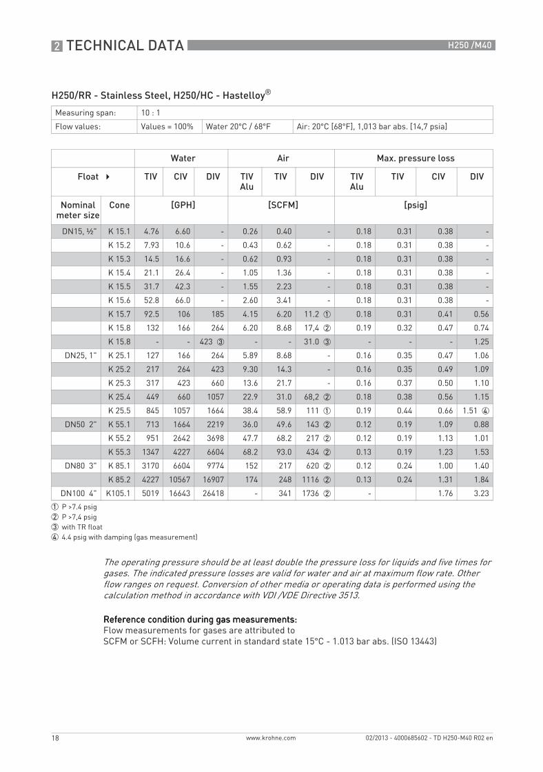
H250/RR - Stainless Steel, H250/HC - Hastelloy®
Reference condition during gas measurements:Reference condition during gas measurements:Reference condition during gas measurements:Reference condition during gas measurements:Flow measurements for gases are attributed toSCFM or SCFH: Volume current in standard state 15°C - 1.013 bar abs. (ISO 13443)
Measuring span: 10 : 1
Flow values: Values = 100% Water 20°C / 68°F Air: 20°C [68°F], 1,013 bar abs. [14,7 psia]
Water Air Max. pressure loss
Float TIV CIV DIV TIVAlu
TIV DIV TIVAlu
TIV CIV DIV
Nominal meter size
Cone [GPH] [SCFM] [psig]
DN15, ½" K 15.1 4.76 6.60 - 0.26 0.40 - 0.18 0.31 0.38 -
K 15.2 7.93 10.6 - 0.43 0.62 - 0.18 0.31 0.38 -
K 15.3 14.5 16.6 - 0.62 0.93 - 0.18 0.31 0.38 -
K 15.4 21.1 26.4 - 1.05 1.36 - 0.18 0.31 0.38 -
K 15.5 31.7 42.3 - 1.55 2.23 - 0.18 0.31 0.38 -
K 15.6 52.8 66.0 - 2.60 3.41 - 0.18 0.31 0.38 -
K 15.7 92.5 106 185 4.15 6.20 11.2 1 0.18 0.31 0.41 0.56
K 15.8 132 166 264 6.20 8.68 17,4 2 0.19 0.32 0.47 0.74
K 15.8 - - 423 3 - - 31.0 3 - - - 1.25
DN25, 1" K 25.1 127 166 264 5.89 8.68 - 0.16 0.35 0.47 1.06
K 25.2 217 264 423 9.30 14.3 - 0.16 0.35 0.49 1.09
K 25.3 317 423 660 13.6 21.7 - 0.16 0.37 0.50 1.10
K 25.4 449 660 1057 22.9 31.0 68,2 2 0.18 0.38 0.56 1.15
K 25.5 845 1057 1664 38.4 58.9 111 1 0.19 0.44 0.66 1.51 4
DN50 2" K 55.1 713 1664 2219 36.0 49.6 143 2 0.12 0.19 1.09 0.88
K 55.2 951 2642 3698 47.7 68.2 217 2 0.12 0.19 1.13 1.01
K 55.3 1347 4227 6604 68.2 93.0 434 2 0.13 0.19 1.23 1.53
DN80 3" K 85.1 3170 6604 9774 152 217 620 2 0.12 0.24 1.00 1.40
K 85.2 4227 10567 16907 174 248 1116 2 0.13 0.24 1.31 1.84
DN100 4" K105.1 5019 16643 26418 - 341 1736 2 - 1.76 3.23
1 P >7.4 psig2 P >7,4 psig3 with TR float4 4.4 psig with damping (gas measurement)
The operating pressure should be at least double the pressure loss for liquids and five times for gases. The indicated pressure losses are valid for water and air at maximum flow rate. Other flow ranges on request. Conversion of other media or operating data is performed using the calculation method in accordance with VDI /VDE Directive 3513.
TD_H250_M40_R02_en_685602_PRT.book Page 18 Wednesday, February 6, 2013 10:55 AM

TECHNICAL DATA 2
19
H250 /M40
www.krohne.com02/2013 - 4000685602 - TD H250-M40 R02 en
H250/C - Ceramic/PTFE
Reference condition during gas measurements:Reference condition during gas measurements:Reference condition during gas measurements:Reference condition during gas measurements:Flow measurements for gases are attributed toNl/h or Nm3/h: Volume current in standard state 0°C - 1.013 bar abs. (DIN 1343)
Measuring span: 10 : 1
Flow values: Values = 100% Water 20°C / 68°F Air: 20°C [68°F], 1,013 bar abs. [14,7 psia]
Flow Max. pressure loss
Water Air Water Air
Liner /Float
PTFE Ceramic PTFE Ceramic PTFE Ceramic PTFE Ceramic
Nominal meter size
Cone [l/h] [Nm3/h] [mbar]
DN15, ½" E 17.2 25 30 0,7 - 65 62 65 62
E 17.3 40 50 1,1 1.8 66 64 66 64
E 17.4 63 70 1,8 2.4 66 66 66 66
E 17.5 100 130 2,8 4 68 68 68 68
E 17.6 160 200 4,8 6.5 72 70 72 70
E 17.7 250 250 7 9 86 72 86 72
E 17.8 400 - 10 - 111 - 111 -
DN25, 1" E 27.1 630 500 16 18 70 55 70 55
E 27.2 1000 700 30 22 80 60 80 60
E 27.3 1600 1100 45 30 108 70 108 70
E 27.4 2500 1600 70 50 158 82 158 82
E 27.5 4000 1 2500 120 75 290 100 194 100
DN50, 2" E 57.1 4000 4500 110 140 81 70 81 70
E 57.2 6300 6300 180 200 110 80 110 80
E 57.3 10000 11000 250 350 170 110 170 110
E 57.4 16000 1 - - - 284 - - -
DN80, 3" E 87.1 16000 16000 - - 81 70 - -
E 87.2 25000 25000 - - 95 85 - -
E 87.3 40000 1 - - - 243 - - -
DN100, 4" E 107.1 40000 - - - 100 - - -
E 107.2 60000 1 - - - 225 - - -
1 special float
The operating pressure should be at least double the pressure loss for liquids and five times for gases. The indicated pressure losses are valid for water and air at maximum flow rate. Other flow ranges on request. Conversion of other media or operating data is performed using the calculation method in accordance with VDI /VDE Directive 3513.
TD_H250_M40_R02_en_685602_PRT.book Page 19 Wednesday, February 6, 2013 10:55 AM

2 TECHNICAL DATA
20
H250 /M40
www.krohne.com 02/2013 - 4000685602 - TD H250-M40 R02 en
H250/C - Ceramic/PTFE
Reference condition for gas measurements:Reference condition for gas measurements:Reference condition for gas measurements:Reference condition for gas measurements:Flow measurements for gases are attributed toSCFM or SCFH: Volume current in standard state 15°C - 1.013 bar abs. (ISO 13443)
Measuring span: 10 : 1
Flow values: Values = 100% Water 20°C / 68°F Air: 20°C [68°F], 1,013 bar abs. [14,7 psia]
Flow Max. pressure loss
Water Air Water Air
Liner / Float PTFE Ceramic PTFE Ceramic PTFE Ceramic PTFE Ceramic
Nominal meter size
Cone [GPH] [SCFM] [psig]
DN15, ½" E 17.2 6.60 7.93 - 0,94 0,90 0,94 0,90
E 17.3 10.6 13.2 1.12 0,96 0,93 0,96 0,93
E 17.4 16.6 18.5 1.49 0,96 0,96 0,96 0,96
E 17.5 26.4 34.3 2.48 0,99 0,99 0,99 0,99
E 17.6 42.3 52.8 4.03 1,04 1,02 1,02 1,02
E 17.7 66.0 66.0 5.58 1,25 1,04 1,25 1,04
E 17.8 106 - - 1,61 - 1,61 -
DN25, 1" E 27.1 166 132 11.2 1,02 0,80 1,02 0,80
E 27.2 264 185 13.6 1,16 0,87 1,16 0,87
E 27.3 423 291 18.6 1,57 1,02 1,57 1,02
E 27.4 660 423 31.0 2,29 1,19 2,29 1,19
E 27.5 1056 1 660 46.5 4,21 1,45 2,81 1,45
DN50, 2" E 57.1 1057 1189 86.8 1,18 1,02 1,18 1,02
E 57.2 1664 1664 124 1,60 1,16 1,60 1,16
E 57.3 2642 2906 217 2,47 1,60 2,47 1,60
E 57.4 4226 1 - - 4,12 - - -
DN80, 3" E 87.1 4227 4227 - 1,18 1,02 - -
E 87.2 6604 6604 - 1,38 1,23 -
E 87.3 10567 1 - - 3,55 - -
DN100, 4" E 107.1 10567 - - 1,45 - -
E 107.2 15850 1 - - 3,29 - -
1 special float
The operating pressure should be at least double the pressure loss for liquids and five times for gases. The indicated pressure losses are valid for water and air at maximum flow rate. Other flow ranges on request. Conversion of other media or operating data is performed using the calculation method in accordance with VDI /VDE Directive 3513.
TD_H250_M40_R02_en_685602_PRT.book Page 20 Wednesday, February 6, 2013 10:55 AM
TECHNICAL DATA 2
21
H250 /M40
www.krohne.com02/2013 - 4000685602 - TD H250-M40 R02 en
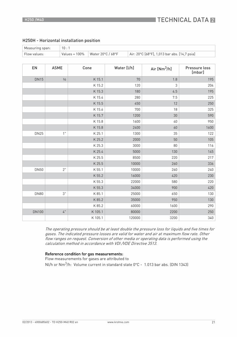
H250H - Horizontal installation position
Reference condition for gas measurements:Reference condition for gas measurements:Reference condition for gas measurements:Reference condition for gas measurements:Flow measurements for gases are attributed toNl/h or Nm3/h: Volume current in standard state 0°C - 1.013 bar abs. (DIN 1343)
Measuring span: 10 : 1
Flow values: Values = 100% Water 20°C / 68°F Air: 20°C [68°F], 1,013 bar abs. [14,7 psia]
EN ASME Cone Water [l/h] Air [Nm3/h] Pressure loss[mbar]
DN15 ½ K 15.1 70 1.8 195
K 15.2 120 3 204
K 15.3 180 4.5 195
K 15.4 280 7.5 225
K 15.5 450 12 250
K 15.6 700 18 325
K 15.7 1200 30 590
K 15.8 1600 40 950
K 15.8 2400 60 1600
DN25 1" K 25.1 1300 35 122
K 25.2 2000 50 105
K 25.3 3000 80 116
K 25.4 5000 130 145
K 25.5 8500 220 217
K 25.5 10000 260 336
DN50 2" K 55.1 10000 260 240
K 55.2 16000 420 230
K 55.3 22000 580 220
K 55.3 34000 900 420
DN80 3" K 85.1 25000 650 130
K 85.2 35000 950 130
K 85.2 60000 1600 290
DN100 4" K 105.1 80000 2200 250
K 105.1 120000 3200 340
The operating pressure should be at least double the pressure loss for liquids and five times for gases. The indicated pressure losses are valid for water and air at maximum flow rate. Other flow ranges on request. Conversion of other media or operating data is performed using the calculation method in accordance with VDI /VDE Directive 3513.
TD_H250_M40_R02_en_685602_PRT.book Page 21 Wednesday, February 6, 2013 10:55 AM

2 TECHNICAL DATA
22
H250 /M40
www.krohne.com 02/2013 - 4000685602 - TD H250-M40 R02 en
H250H - Horizontal installation position
Reference condition for gas measurements:Reference condition for gas measurements:Reference condition for gas measurements:Reference condition for gas measurements:Flow measurements for gases are attributed toSCFM or SCFH: Volume current in standard state 15°C - 1.013 bar abs. (ISO 13443)
Measuring span: 10 : 1
Flow values: Values = 100% Water 20°C / 68°F Air: 20°C [68°F], 1,013 bar abs. [14,7 psia]
EN ASME Cone Wasser [GPH] Luft [SCFM] Pressure loss[psig]
DN15 1/2" K 15.1 18.5 1.12 2.87
K 15.2 31.7 1.86 3.00
K 15.3 47.6 2.79 2.87
K 15.4 74.0 4.65 3.31
K 15.5 119 7.44 3.68
K 15.6 185 11.2 4.78
K 15.7 317 18.6 8.68
K 15.8 423 24.8 14.0
K 15.8 634 37.2 23.5
DN25 1" K 25.1 343 21.7 1.79
K 25.2 528 31.0 1.54
K 25.3 793 49.6 1.71
K 25.4 1321 80.6 2.13
K 25.5 2245 136 3.19
K 25.5 2642 161 4.94
DN50 2" K 55.1 2642 161 3.53
K 55.2 4227 260 3.38
K 55.3 5812 360 3.23
K 55.3 8982 558 6.17
DN80 3" K 85.1 6604 403 1.91
K 85.2 9246 589 1.91
K 85.2 15851 992 4.26
DN100 4" K 105.1 21134 1364 3.68
K 105.1 31701 1984 5.00
The operating pressure should be at least double the pressure loss for liquids and five times for gases. The indicated pressure losses are valid for water and air at maximum flow rate. Other flow ranges on request. Conversion of other media or operating data is performed using the calculation method in accordance with VDI /VDE Directive 3513.
TD_H250_M40_R02_en_685602_PRT.book Page 22 Wednesday, February 6, 2013 10:55 AM
TECHNICAL DATA 2
23
H250 /M40
www.krohne.com02/2013 - 4000685602 - TD H250-M40 R02 en
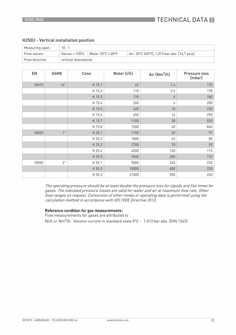
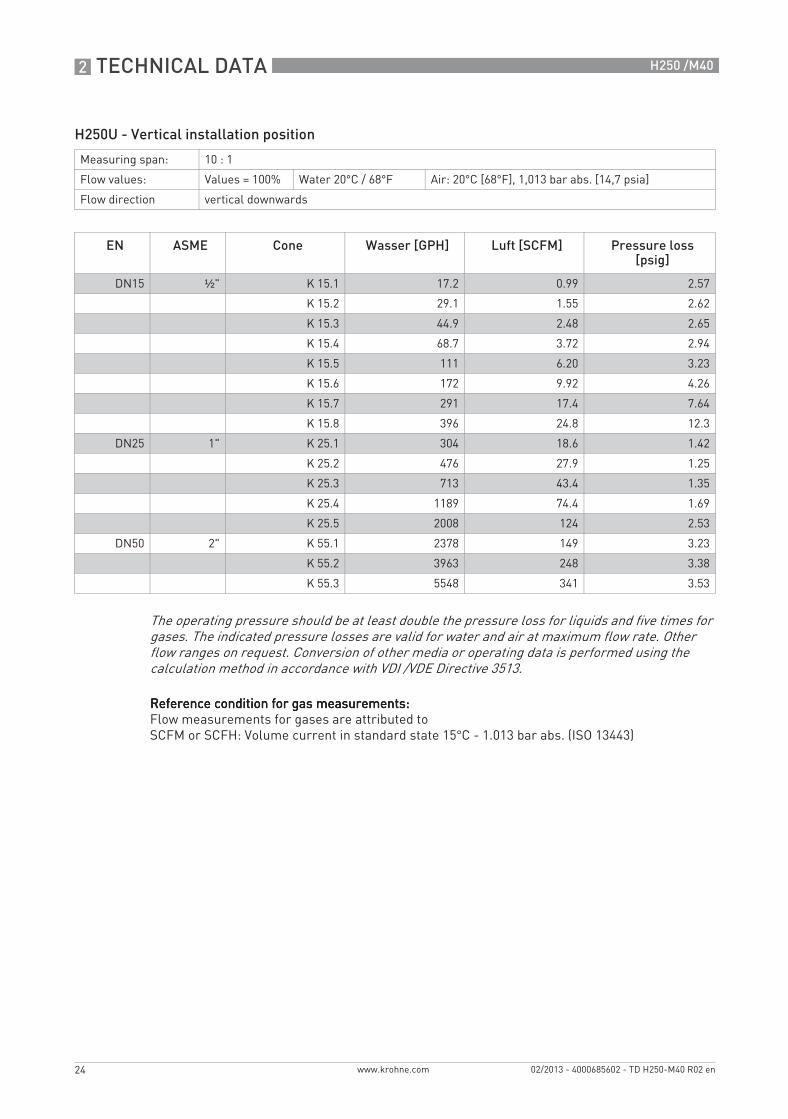
H250U - Vertical installation position
Reference condition for gas measurements:Reference condition for gas measurements:Reference condition for gas measurements:Reference condition for gas measurements:Flow measurements for gases are attributed toNl/h or Nm3/h: Volume current in standard state 0°C - 1.013 bar abs. (DIN 1343)
Measuring span: 10 : 1
Flow values: Values = 100% Water 20°C / 68°F Air: 20°C [68°F], 1,013 bar abs. [14,7 psia]
Flow direction vertical downwards
EN ASME Cone Water [l/h] Air [Nm3/h] Pressure loss[mbar]
DN15 ½" K 15.1 65 1.6 175
K 15.2 110 2.5 178
K 15.3 170 4 180
K 15.4 260 6 200
K 15.5 420 10 220
K 15.6 650 16 290
K 15.7 1100 28 520
K 15.8 1500 40 840
DN25 1" K 25.1 1150 30 97
K 25.2 1800 45 85
K 25.3 2700 70 92
K 25.4 4500 120 115
K 25.5 7600 200 172
DN50 2" K 55.1 9000 240 220
K 55.2 15000 400 230
K 55.3 21000 550 240
The operating pressure should be at least double the pressure loss for liquids and five times for gases. The indicated pressure losses are valid for water and air at maximum flow rate. Other flow ranges on request. Conversion of other media or operating data is performed using the calculation method in accordance with VDI /VDE Directive 3513.
TD_H250_M40_R02_en_685602_PRT.book Page 23 Wednesday, February 6, 2013 10:55 AM
2 TECHNICAL DATA
24
H250 /M40
www.krohne.com 02/2013 - 4000685602 - TD H250-M40 R02 en
H250U - Vertical installation position
Reference condition for gas measurements:Reference condition for gas measurements:Reference condition for gas measurements:Reference condition for gas measurements:Flow measurements for gases are attributed toSCFM or SCFH: Volume current in standard state 15°C - 1.013 bar abs. (ISO 13443)
Measuring span: 10 : 1
Flow values: Values = 100% Water 20°C / 68°F Air: 20°C [68°F], 1,013 bar abs. [14,7 psia]
Flow direction vertical downwards
EN ASME Cone Wasser [GPH] Luft [SCFM] Pressure loss[psig]
DN15 ½" K 15.1 17.2 0.99 2.57
K 15.2 29.1 1.55 2.62
K 15.3 44.9 2.48 2.65
K 15.4 68.7 3.72 2.94
K 15.5 111 6.20 3.23
K 15.6 172 9.92 4.26
K 15.7 291 17.4 7.64
K 15.8 396 24.8 12.3
DN25 1" K 25.1 304 18.6 1.42
K 25.2 476 27.9 1.25
K 25.3 713 43.4 1.35
K 25.4 1189 74.4 1.69
K 25.5 2008 124 2.53
DN50 2" K 55.1 2378 149 3.23
K 55.2 3963 248 3.38
K 55.3 5548 341 3.53
The operating pressure should be at least double the pressure loss for liquids and five times for gases. The indicated pressure losses are valid for water and air at maximum flow rate. Other flow ranges on request. Conversion of other media or operating data is performed using the calculation method in accordance with VDI /VDE Directive 3513.
TD_H250_M40_R02_en_685602_PRT.book Page 24 Wednesday, February 6, 2013 10:55 AM
INSTALLATION 3
25
H250 /M40
www.krohne.com02/2013 - 4000685602 - TD H250-M40 R02 en
Installation
3.1 Intended use
The variable area flowmeters are suitable for measuring clean gases, vapours and liquids.
Intended use:• The product may not contain any ferromagnetic particles or solids. It may be necessary to
install magnetic filters or mechanical filters.• The product must be sufficiently liquid and free of deposits.• Avoid pressure surges and pulsing flows.• Open valves slowly. Do not use solenoid valves.
Use suitable measures to eliminate compression vibrations during gas measurements:• Short pipeline lengths to next restriction• Nominal pipe size not greater than nominal device size• Use of floats with damping• Increase in operating pressure (while taking into account the resulting change in density and
thus change in scale)
Observe installation conditions according to VDI/VDE 3513-3
Responsibility for the use of the measuring devices with regard to suitability, intended use and corrosion resistance of the used materials against the measured fluid lies solely with the operator.
The manufacturer is not liable for any damage resulting from improper use or use for other than the intended purpose.
For devices used in hazardous areas, additional safety notes apply; please refer to the Ex documentation.
Responsibility for the use of the measurement devices with regard to suitability, intended use and corrosion resistance of the used materials against the measured fluid lies solely with the operator.The manufacturer is not liable for any damage resulting from improper use or use for other than the intended purpose.Do not use any abrasive media containing solid particles or highly viscous media.
TD_H250_M40_R02_en_685602_PRT.book Page 25 Wednesday, February 6, 2013 10:55 AM

3 INSTALLATION
26
H250 /M40
www.krohne.com 02/2013 - 4000685602 - TD H250-M40 R02 en
3.2 Installation conditions
When installing the device in the piping, the following points must be observed:
• The variable area flowmeter must be installed vertically (measuring principle). Flow direction from bottom to top. For installation recommendations please refer also to VDI/VDE 3513 Sheet 3.H250Hs are installed horizontally and H250U devices are installed vertically with the flow direction from top to bottom.
• A straight unimpeded inlet run of ≥ 5x DN upstream of the device and a straight outlet run of ≥ 3x DN downstream of the device are recommended.
• Screws, bolts and gaskets are to be provided by the customer and must be selected in accordance with the pressure rating of the connection or the operating pressure.
• The inside diameter of the flange deviates from the standard dimensions. Flange seal standard DIN 2690 can be applied without any limitation.
• Align the gaskets. Tighten the nuts with the tightening torques of the appropriate pressure rating. For devices with PTFE liner or ceramic liner and PTFE raised faces, see chapter "Tightening torques".
• Control devices are to be positioned downstream of the measuring device.• Shutoff devices are preferably to be positioned upstream of the measuring device.• Before connecting, blow or flush out the pipes leading to the device.• Pipes for gas flow need to be dried before the device is installed.• Use connectors suitable for the particular device version.• Align the pipes centrically with the connection bores on the measuring device so they are free
of stresses.• If necessary, the piping has to be supported to reduce the vibrations transmitted to the
measuring device.• Do not lay signal cables directly next to cables for the power supply.
TD_H250_M40_R02_en_685602_PRT.book Page 26 Wednesday, February 6, 2013 10:55 AM
INSTALLATION 3
27
H250 /M40
www.krohne.com02/2013 - 4000685602 - TD H250-M40 R02 en
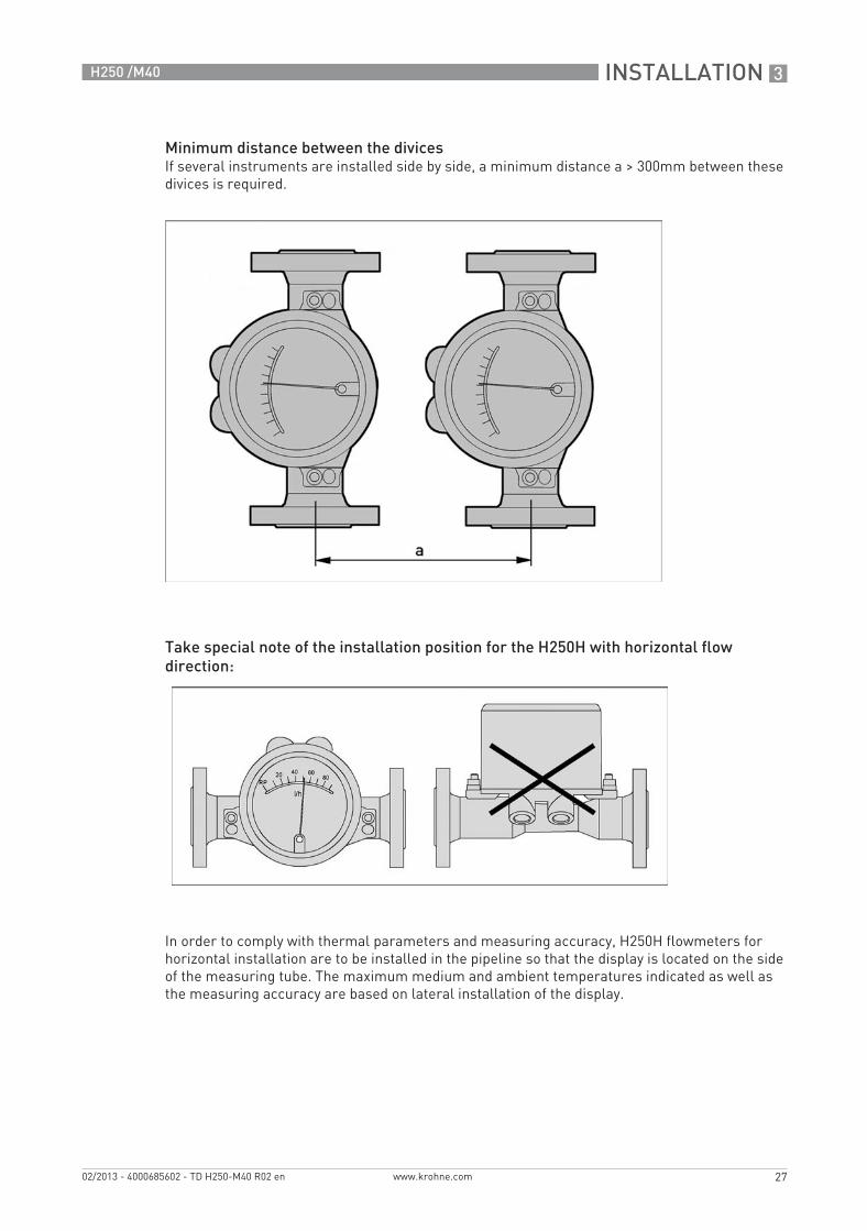
Minimum distance between the divicesIf several instruments are installed side by side, a minimum distance a > 300mm between these divices is required.
Take special note of the installation position for the H250H with horizontal flow direction:
In order to comply with thermal parameters and measuring accuracy, H250H flowmeters for horizontal installation are to be installed in the pipeline so that the display is located on the side of the measuring tube. The maximum medium and ambient temperatures indicated as well as the measuring accuracy are based on lateral installation of the display.
TD_H250_M40_R02_en_685602_PRT.book Page 27 Wednesday, February 6, 2013 10:55 AM
3 INSTALLATION
28
H250 /M40
www.krohne.com 02/2013 - 4000685602 - TD H250-M40 R02 en
3.2.1 Tightening torques
For measuring devices with PTFE liner or ceramic liner and PTFE raised face, tighten the flange threads with the following torques:
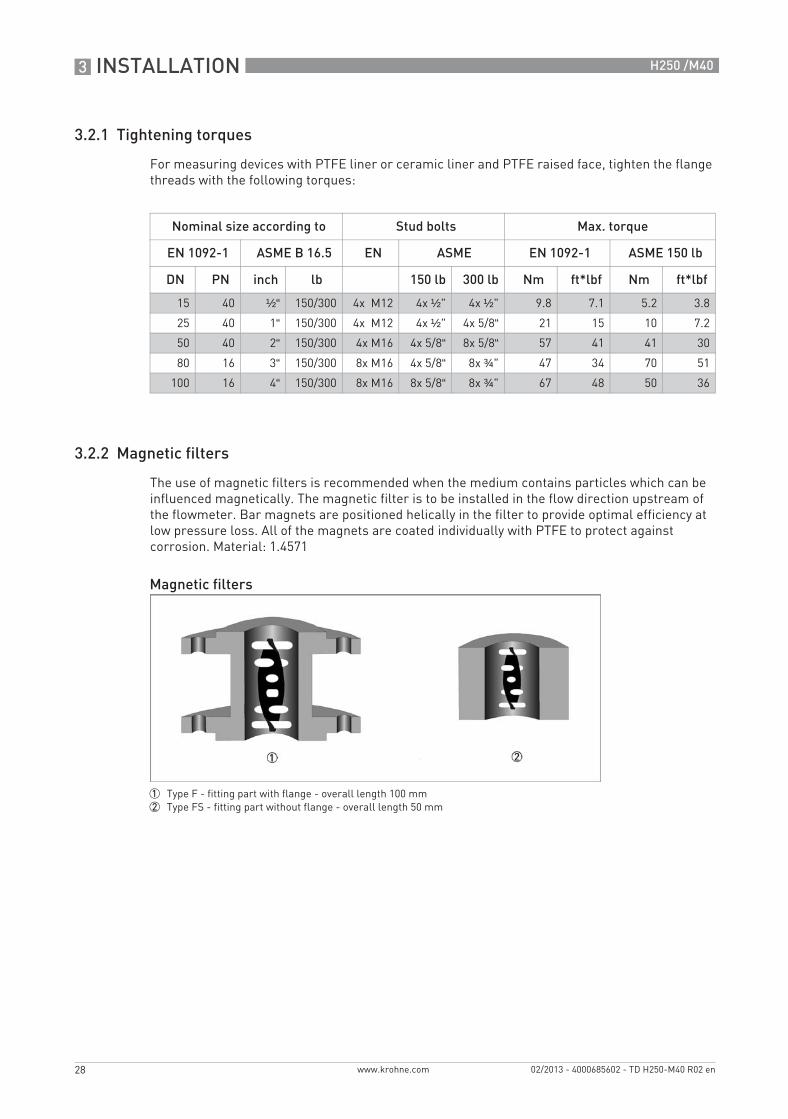
3.2.2 Magnetic filters
The use of magnetic filters is recommended when the medium contains particles which can be influenced magnetically. The magnetic filter is to be installed in the flow direction upstream of the flowmeter. Bar magnets are positioned helically in the filter to provide optimal efficiency at low pressure loss. All of the magnets are coated individually with PTFE to protect against corrosion. Material: 1.4571
Nominal size according to Stud bolts Max. torque
EN 1092-1 ASME B 16.5 EN ASME EN 1092-1 ASME 150 lb
DN PN inch lb 150 lb 300 lb Nm ft*lbf Nm ft*lbf
15 40 ½“ 150/300 4x M12 4x ½" 4x ½" 9.8 7.1 5.2 3.8
25 40 1“ 150/300 4x M12 4x ½" 4x 5/8“ 21 15 10 7.2
50 40 2“ 150/300 4x M16 4x 5/8“ 8x 5/8“ 57 41 41 30
80 16 3“ 150/300 8x M16 4x 5/8“ 8x ¾" 47 34 70 51
100 16 4“ 150/300 8x M16 8x 5/8“ 8x ¾" 67 48 50 36
Magnetic filters
1 Type F - fitting part with flange - overall length 100 mm2 Type FS - fitting part without flange - overall length 50 mm
TD_H250_M40_R02_en_685602_PRT.book Page 28 Wednesday, February 6, 2013 10:55 AM
INSTALLATION 3
29
H250 /M40
www.krohne.com02/2013 - 4000685602 - TD H250-M40 R02 en
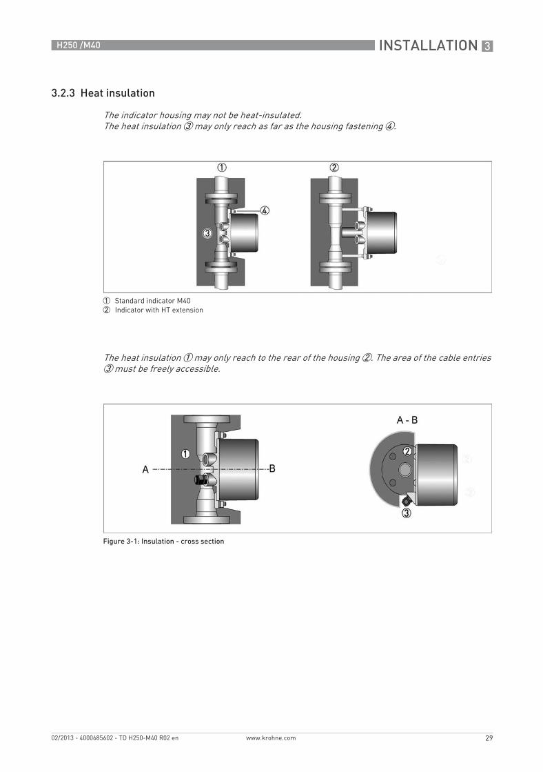
3.2.3 Heat insulation
The indicator housing may not be heat-insulated.The heat insulation 3 may only reach as far as the housing fastening 4.
1 Standard indicator M402 Indicator with HT extension
The heat insulation 1 may only reach to the rear of the housing 2. The area of the cable entries 3 must be freely accessible.
Figure 3-1: Insulation - cross section
TD_H250_M40_R02_en_685602_PRT.book Page 29 Wednesday, February 6, 2013 10:55 AM

3 INSTALLATION
30
H250 /M40
www.krohne.com 02/2013 - 4000685602 - TD H250-M40 R02 en
3.2.4 Float damping
Float damping is characterised by high standstill times and self-centering. The damping sleeve is made of high performance ceramic or PEEK, depending on the medium and the application. Float damping can also be retrofitted for the user (see Service).
Use of damping• Generally when CIV and DIV floats are used for gas measurement.• For TIV floats (H250/RR and H250/HC only) with an operating primary pressure:
3.2.5 Pointer damping
In principle, the indicating element with its magnetic system contains indicator damping. An additional eddy current brake is advantageous in the event of fluctuating or pulsing flows. The magnets on the eddy current brake surround the pointer vane without touching it, damping its movement. The result is a much steadier pointer position, without distorting the measured value. A turnbuckle ensures a proper fit. The eddy current brake can be retrofitted during operation without recalibrating (see Service).
Nominal size acc. to Operating primary pressure
EN 1092-1 ASME B16.5 [bar] [psig]
DN 50 ½" ≤0.3 ≤4.4
DN25 1" ≤0.3 ≤4.4
DN50 2" ≤0.2 ≤2.9
DN80 3" ≤0.2 ≤2.9
DN 100 4" ≤0.2 ≤2.9
1 Eddy current brake2 Pointer vane3 Bracket4 Pointer cylinder
TD_H250_M40_R02_en_685602_PRT.book Page 30 Wednesday, February 6, 2013 10:55 AM

ELECTRICAL CONNECTIONS 4
31
H250 /M40
www.krohne.com02/2013 - 4000685602 - TD H250-M40 R02 en
Electrical connections
4.1 Security information
All work on the electrical connections may only be carried out with the power disconnected. Take note of the voltage data on the nameplate!Observe the national regulations for electrical installations!For devices used in hazardous areas, additional safety notes apply; please refer to the Ex documentation.Observe without fail the local occupational health and safety regulations. Any work done on the electrical components of the measuring device may only be carried out by properly trained specialists.Look at the device nameplate to ensure that the device is delivered according to your order. Check for the correct supply voltage printed on the nameplate.
4.2 Electrical connection indicator M40
4.2.1 Indicator M40 - limit switches
The M40 indicator can be fitted with a maximum of two limit switches. The limit switch works as a slot sensor which is inductively activated via the semi-circular metal vane of the pointer. The switching points are set using the contact pointer. The position of the contact pointer is displayed on the scale.
The connecting terminals have a pluggable design and can be removed in order to connect the cables. The built-in limit switch types are shown on the indicator.
Electrical connection of the limit switches
Limit switch module
1 Min. contact2 Max. contact3 Locking screw4 Maximum pointer5 Connection terminal
Contact MIN MAX
Terminal no. 1 2 3 4 5 6
Connection 2-wire NAMUR - + - +
Connection 3-wire + - + -
Connection Reed SPST + - + -
TD_H250_M40_R02_en_685602_PRT.book Page 31 Wednesday, February 6, 2013 10:55 AM
4 ELECTRICAL CONNECTIONS
32
H250 /M40
www.krohne.com 02/2013 - 4000685602 - TD H250-M40 R02 en
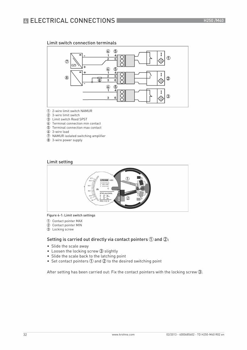
Setting is carried out directly via contact pointers 1 and 2:• Slide the scale away• Loosen the locking screw 3 slightly• Slide the scale back to the latching point• Set contact pointers 1 and 2 to the desired switching point
After setting has been carried out: Fix the contact pointers with the locking screw 3.
Limit switch connection terminals
1 2-wire limit switch NAMUR2 3-wire limit switch3 Limit switch Reed SPST4 Terminal connection min contact5 Terminal connection max contact6 3-wire load7 NAMUR isolated switching amplifier8 3-wire power supply
Limit setting
Figure 4-1: Limit switch settings
1 Contact pointer MAX2 Contact pointer MIN3 Locking screw
TD_H250_M40_R02_en_685602_PRT.book Page 32 Wednesday, February 6, 2013 10:55 AM
ELECTRICAL CONNECTIONS 4
33
H250 /M40
www.krohne.com02/2013 - 4000685602 - TD H250-M40 R02 en
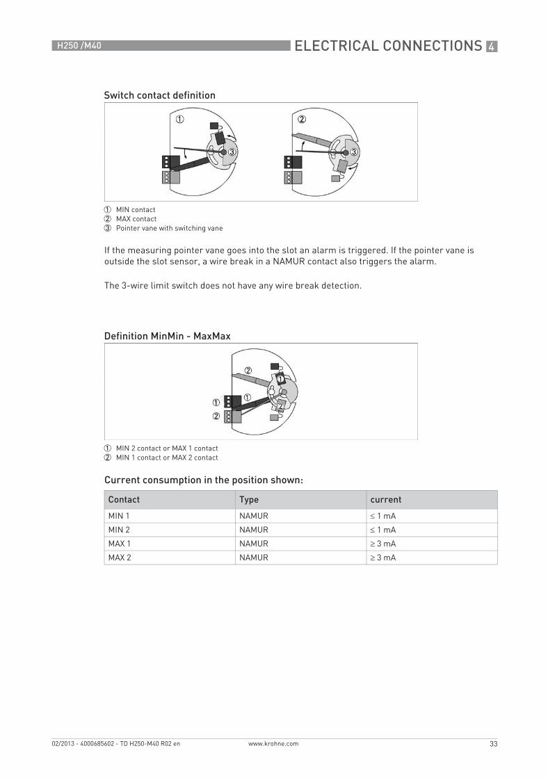
If the measuring pointer vane goes into the slot an alarm is triggered. If the pointer vane is outside the slot sensor, a wire break in a NAMUR contact also triggers the alarm.
The 3-wire limit switch does not have any wire break detection.
Current consumption in the position shown:
Switch contact definition
1 MIN contact2 MAX contact3 Pointer vane with switching vane
Definition MinMin - MaxMax
1 MIN 2 contact or MAX 1 contact2 MIN 1 contact or MAX 2 contact
Contact Type current
MIN 1 NAMUR ≤ 1 mA
MIN 2 NAMUR ≤ 1 mA
MAX 1 NAMUR ≥ 3 mA
MAX 2 NAMUR ≥ 3 mA
TD_H250_M40_R02_en_685602_PRT.book Page 33 Wednesday, February 6, 2013 10:55 AM
4 ELECTRICAL CONNECTIONS
34
H250 /M40
www.krohne.com 02/2013 - 4000685602 - TD H250-M40 R02 en
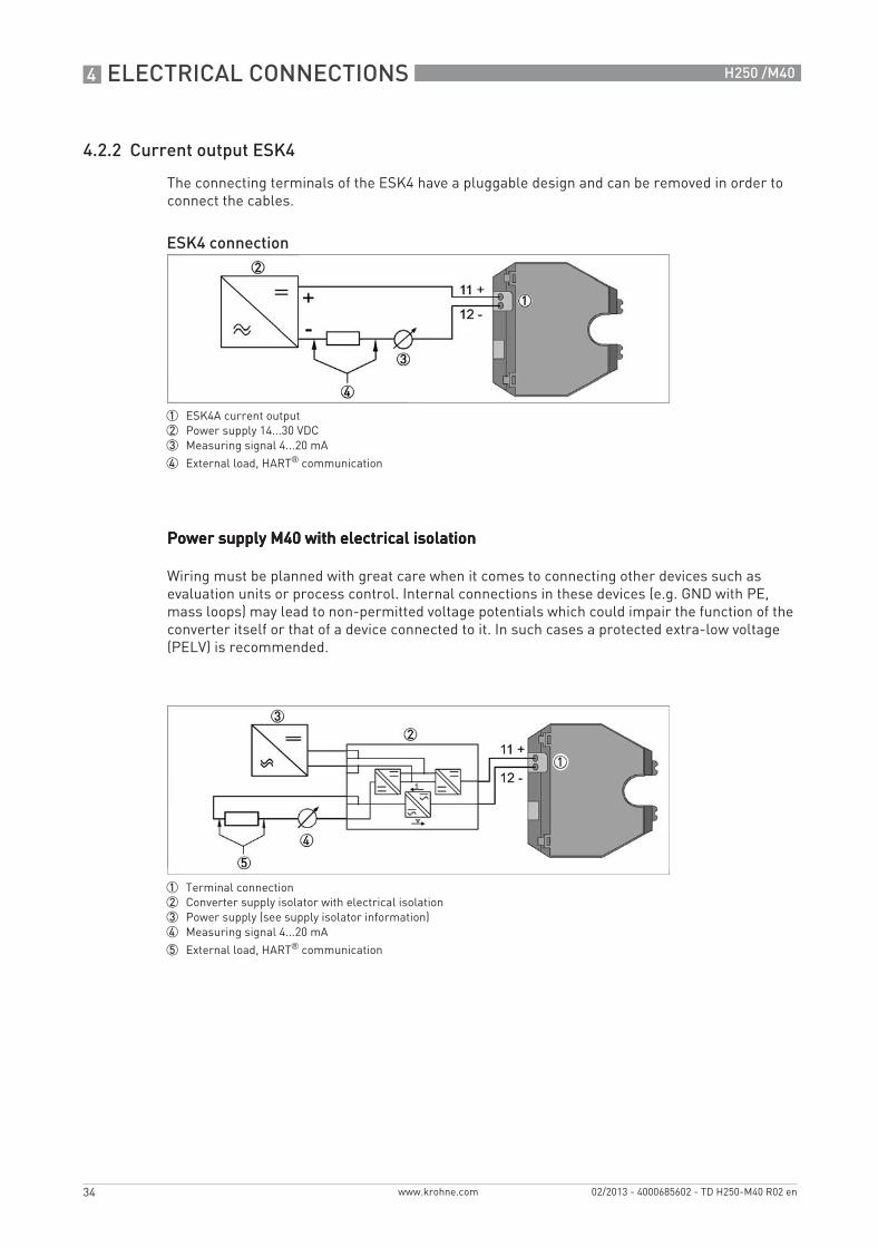
4.2.2 Current output ESK4
The connecting terminals of the ESK4 have a pluggable design and can be removed in order to connect the cables.
Power supply M40 with electrical isolationPower supply M40 with electrical isolationPower supply M40 with electrical isolationPower supply M40 with electrical isolation
Wiring must be planned with great care when it comes to connecting other devices such as evaluation units or process control. Internal connections in these devices (e.g. GND with PE, mass loops) may lead to non-permitted voltage potentials which could impair the function of the converter itself or that of a device connected to it. In such cases a protected extra-low voltage (PELV) is recommended.
ESK4 connection
1 ESK4A current output2 Power supply 14...30 VDC3 Measuring signal 4...20 mA
4 External load, HART® communication
1 Terminal connection2 Converter supply isolator with electrical isolation3 Power supply (see supply isolator information)4 Measuring signal 4...20 mA
5 External load, HART® communication
TD_H250_M40_R02_en_685602_PRT.book Page 34 Wednesday, February 6, 2013 10:55 AM
ELECTRICAL CONNECTIONS 4
35
H250 /M40
www.krohne.com02/2013 - 4000685602 - TD H250-M40 R02 en
Power supplyPower supplyPower supplyPower supply
The required supply voltage can be calculated using the formula below:
Uext. = RL.24 mA + 14 V
whereUext. = the minimum supply voltage andRL = the total measuring loop resistance.
HARTHARTHARTHART® communicationWhen HART® communication is carried out with the ESK4, the analogue measured data transmission (4...20 mA) is not impaired in any way.
Exception for multidrop operation. In multidrop mode, a maximum of 15 devices with HART® function can be operated in parallel, whereby their current outputs are switched inactive (I approx. 4.5 mA per device).
The feed voltage must be between 14 VDC and 30 VDC. This is based on the total resistance of the measuring loop. To determine this, add up the resistances of each component in the measuring loop (not including the level meter).
The power supply has to be able to supply a minimum of 30 mA.
TD_H250_M40_R02_en_685602_PRT.book Page 35 Wednesday, February 6, 2013 10:55 AM

4 ELECTRICAL CONNECTIONS
36
H250 /M40
www.krohne.com 02/2013 - 4000685602 - TD H250-M40 R02 en
Load for HART® communication
The maximum load resistance is calculated as follows:
ConfigurationThe ESK can be configured via HART® communication. DD (Device Descriptions) for AMS 10x, AMS 11x and PDM 6.0 as well as a DTM (Device Type Manager) for PACTware™ 3.0.2.28(3.0 SP5), 3.6.0.3(3.6 SP2) and 4.0.0.6 are available for configuration. They can be downloaded free of charge from our website.
The current flow rate can be transmitted using the integrated HART® communication. A flow counter can be configured. Two limit values can be monitored. The limit values are assigned either to flow values or to the counter overflow.
Self monitoring - DiagnosticsDuring both start-up and operation, a wide variety of diagnostic functions are performed cyclically in the ESK4, in order to guarantee function reliability. When an error is detected, a failure signal (high) is activated (current > 21 mA, typically 22 mA) via the analog output. More detailed information can also be obtained via HART®(CMD#48). The failure signal is not activated in the event of information and warnings.
Diagnostic functions (Monitoring):• Plausibility of FRAM data• Plausibility of ROM data• Working range of internal reference voltages• Signal detection of the measuring range of the internal sensors• Temperature compensation of the internal sensors• Calibration based on the application• Plausibility of counting value• Plausibility of physical unit, system and selected unit
A load of at least 230 Ohm is required for HART® communication.
Use a twisted two-core cable to prevent electrical interference from impeding the DC output signal. In some cases a shielded cable may be necessary. The cable shield may only be earthed (grounded) at one place (on the power supply unit).
TD_H250_M40_R02_en_685602_PRT.book Page 36 Wednesday, February 6, 2013 10:55 AM
ELECTRICAL CONNECTIONS 4
37
H250 /M40
www.krohne.com02/2013 - 4000685602 - TD H250-M40 R02 en
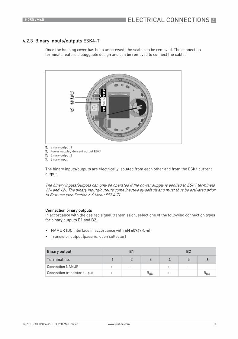
4.2.3 Binary inputs/outputs ESK4-T
Once the housing cover has been unscrewed, the scale can be removed. The connection terminals feature a pluggable design and can be removed to connect the cables.
The binary inputs/outputs are electrically isolated from each other and from the ESK4 current output.
Connection binary outputsConnection binary outputsConnection binary outputsConnection binary outputsIn accordance with the desired signal transmission, select one of the following connection types for binary outputs B1 and B2:
• NAMUR (DC interface in accordance with EN 60947-5-6)• Transistor output (passive, open collector)
1 Binary output 12 Power supply / durrent output ESK43 Binary output 24 Binary input
The binary inputs/outputs can only be operated if the power supply is applied to ESK4 terminals 11+ and 12-. The binary inputs/outputs come inactive by default and must thus be activated prior to first use (see Section 6.6 Menu ESK4-T)
Binary output B1 B2
Terminal no. 1 2 3 4 5 6
Connection NAMUR + - + -
Connection transistor output + BOC + BOC
TD_H250_M40_R02_en_685602_PRT.book Page 37 Wednesday, February 6, 2013 10:55 AM
4 ELECTRICAL CONNECTIONS
38
H250 /M40
www.krohne.com 02/2013 - 4000685602 - TD H250-M40 R02 en
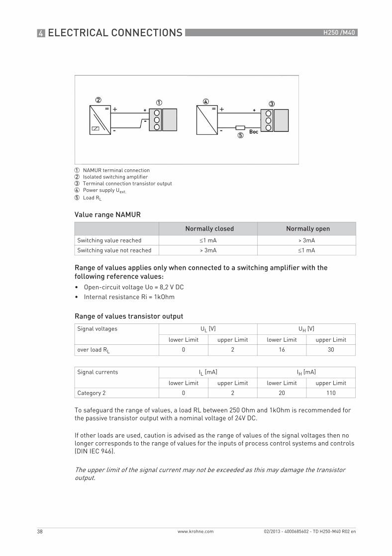
Value range NAMUR
Range of values applies only when connected to a switching amplifier with the following reference values:• Open-circuit voltage Uo = 8,2 V DC• Internal resistance Ri = 1kOhm
Range of values transistor output
To safeguard the range of values, a load RL between 250 Ohm and 1kOhm is recommended for the passive transistor output with a nominal voltage of 24V DC.
If other loads are used, caution is advised as the range of values of the signal voltages then no longer corresponds to the range of values for the inputs of process control systems and controls (DIN IEC 946).
1 NAMUR terminal connection2 Isolated switching amplifier3 Terminal connection transistor output4 Power supply Uext.5 Load RL
Normally closed Normally open
Switching value reached ≤1 mA > 3mA
Switching value not reached > 3mA ≤1 mA
Signal voltages UL [V] UH [V]
lower Limit upper Limit lower Limit upper Limit
over load RL 0 2 16 30
Signal currents IL [mA] IH [mA]
lower Limit upper Limit lower Limit upper Limit
Category 2 0 2 20 110
The upper limit of the signal current may not be exceeded as this may damage the transistor output.
TD_H250_M40_R02_en_685602_PRT.book Page 38 Wednesday, February 6, 2013 10:55 AM
ELECTRICAL CONNECTIONS 4
39
H250 /M40
www.krohne.com02/2013 - 4000685602 - TD H250-M40 R02 en
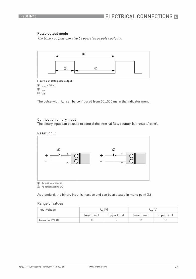
Pulse output mode
The pulse width ton can be configured from 50...500 ms in the indicator menu.
Connection binary inputThe binary input can be used to control the internal flow counter (start/stop/reset).
As standard, the binary input is inactive and can be activated in menu point 3.6.
Range of values
The binary outputs can also be operated as pulse outputs.
Figure 4-2: Data pulse output
1 fmax = 10 Hz2 ton3 toff
Reset input
1 Function active HI2 Function active LO
Input voltage UL [V] UH [V]
lower Limit upper Limit lower Limit upper Limit
Terminal (7) (8) 0 2 16 30
TD_H250_M40_R02_en_685602_PRT.book Page 39 Wednesday, February 6, 2013 10:55 AM
4 ELECTRICAL CONNECTIONS
40
H250 /M40
www.krohne.com 02/2013 - 4000685602 - TD H250-M40 R02 en
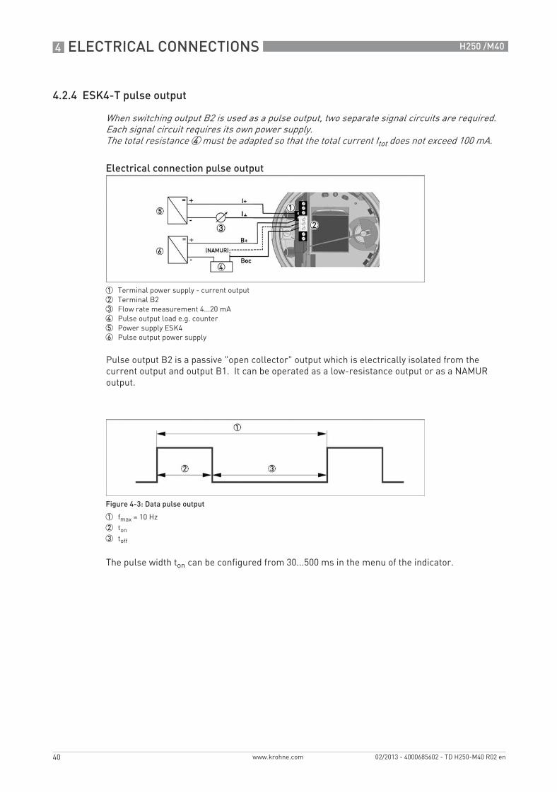
4.2.4 ESK4-T pulse output
Pulse output B2 is a passive "open collector" output which is electrically isolated from the current output and output B1. It can be operated as a low-resistance output or as a NAMUR output.
The pulse width ton can be configured from 30...500 ms in the menu of the indicator.
When switching output B2 is used as a pulse output, two separate signal circuits are required. Each signal circuit requires its own power supply. The total resistance 4 must be adapted so that the total current Itot does not exceed 100 mA.
Electrical connection pulse output
1 Terminal power supply - current output2 Terminal B23 Flow rate measurement 4...20 mA4 Pulse output load e.g. counter5 Power supply ESK46 Pulse output power supply
Figure 4-3: Data pulse output
1 fmax = 10 Hz2 ton3 toff
TD_H250_M40_R02_en_685602_PRT.book Page 40 Wednesday, February 6, 2013 10:55 AM
ELECTRICAL CONNECTIONS 4
41
H250 /M40
www.krohne.com02/2013 - 4000685602 - TD H250-M40 R02 en
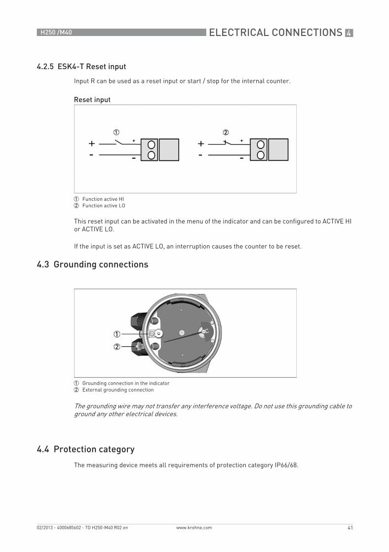
4.2.5 ESK4-T Reset input
Input R can be used as a reset input or start / stop for the internal counter.
This reset input can be activated in the menu of the indicator and can be configured to ACTIVE HI or ACTIVE LO.
If the input is set as ACTIVE LO, an interruption causes the counter to be reset.
4.3 Grounding connections
4.4 Protection category
The measuring device meets all requirements of protection category IP66/68.
Reset input
1 Function active HI2 Function active LO
1 Grounding connection in the indicator2 External grounding connection
The grounding wire may not transfer any interference voltage. Do not use this grounding cable to ground any other electrical devices.
TD_H250_M40_R02_en_685602_PRT.book Page 41 Wednesday, February 6, 2013 10:55 AM
4 ELECTRICAL CONNECTIONS
42
H250 /M40
www.krohne.com 02/2013 - 4000685602 - TD H250-M40 R02 en
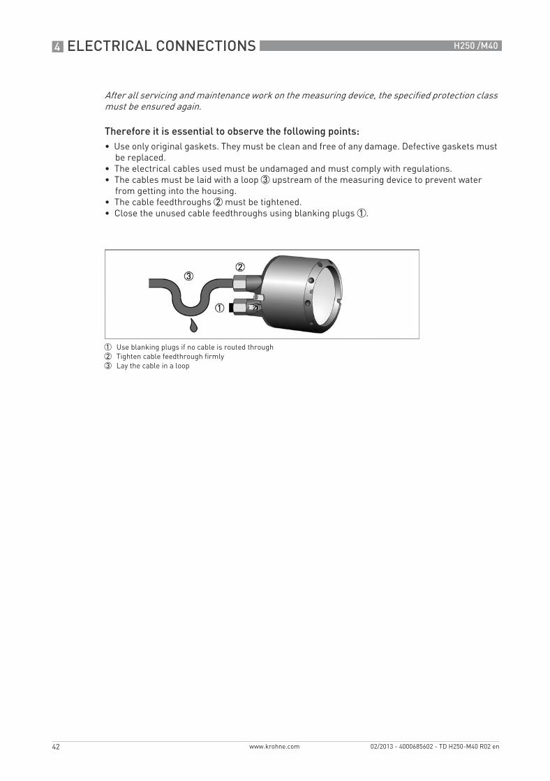
Therefore it is essential to observe the following points:• Use only original gaskets. They must be clean and free of any damage. Defective gaskets must
be replaced.• The electrical cables used must be undamaged and must comply with regulations.• The cables must be laid with a loop 3 upstream of the measuring device to prevent water
from getting into the housing.• The cable feedthroughs 2 must be tightened.• Close the unused cable feedthroughs using blanking plugs 1.
After all servicing and maintenance work on the measuring device, the specified protection class must be ensured again.
1 Use blanking plugs if no cable is routed through2 Tighten cable feedthrough firmly3 Lay the cable in a loop
TD_H250_M40_R02_en_685602_PRT.book Page 42 Wednesday, February 6, 2013 10:55 AM

ORDER FORM 5
43
H250 /M40
www.krohne.com02/2013 - 4000685602 - TD H250-M40 R02 en
Order form
You can help us to assist you as quickly as possible by giving us a few items of information.
Then please fax this page to the appropriate sales associate. We will then contact you as soon as possible.
Device data
* in preparation
Rating data
Contact data
Connection type:
Nominal connection size:
Pressure rating:
Raised face:
Material of pipeline:
Indicator options: K1 1 K2 2 ESK4 ESK4-T ESK4-FF* ESK4-PA*
Approvals* : None ATEX / IEC-Ex FM / FMc NEPSI
1 1 limit switch2 2 limit switches
Product:
Operating pressure: Absolute pressure
Overpressure
Rated pressure:
Operating temperature:
Rated temperature:
Density: Standard density
Operating density
Viscosity:
Measuring range:
Comments:
Company:
Contact person:
Telephone number:
Fax number:
E-mail:
TD_H250_M40_R02_en_685602_PRT.book Page 43 Wednesday, February 6, 2013 10:55 AM
KROHNE product overview
• Electromagnetic flowmeters
• Variable area flowmeters
• Ultrasonic flowmeters
• Mass flowmeters
• Vortex flowmeters
• Flow controllers
• Level meters
• Temperature meters
• Pressure meters
• Analysis products
• Products and systems for the oil & gas industry
• Measuring systems for the marine industry
Head Office KROHNE Messtechnik GmbHLudwig-Krohne-Str. 547058 Duisburg (Germany)Tel.:+49 (0)203 301 0Fax:+49 (0)203 301 10389 [email protected]
© K
RO
HN
E 02
/201
3 -
4000
6856
02 -
TD
H25
0-M
40 R
02 e
n -
Subj
ect t
o ch
ange
with
out n
otic
e.
The current list of all KROHNE contacts and addresses can be found at:www.krohne.com
KK
K
TD_H250_M40_R02_en_685602_PRT.book Page 44 Wednesday, February 6, 2013 10:55 AM