Embed Size (px)
Citation preview
OPTISWIRL 4070OPTISWIRL 4070OPTISWIRL 4070OPTISWIRL 4070 Technical DatasheetTechnical DatasheetTechnical DatasheetTechnical Datasheet
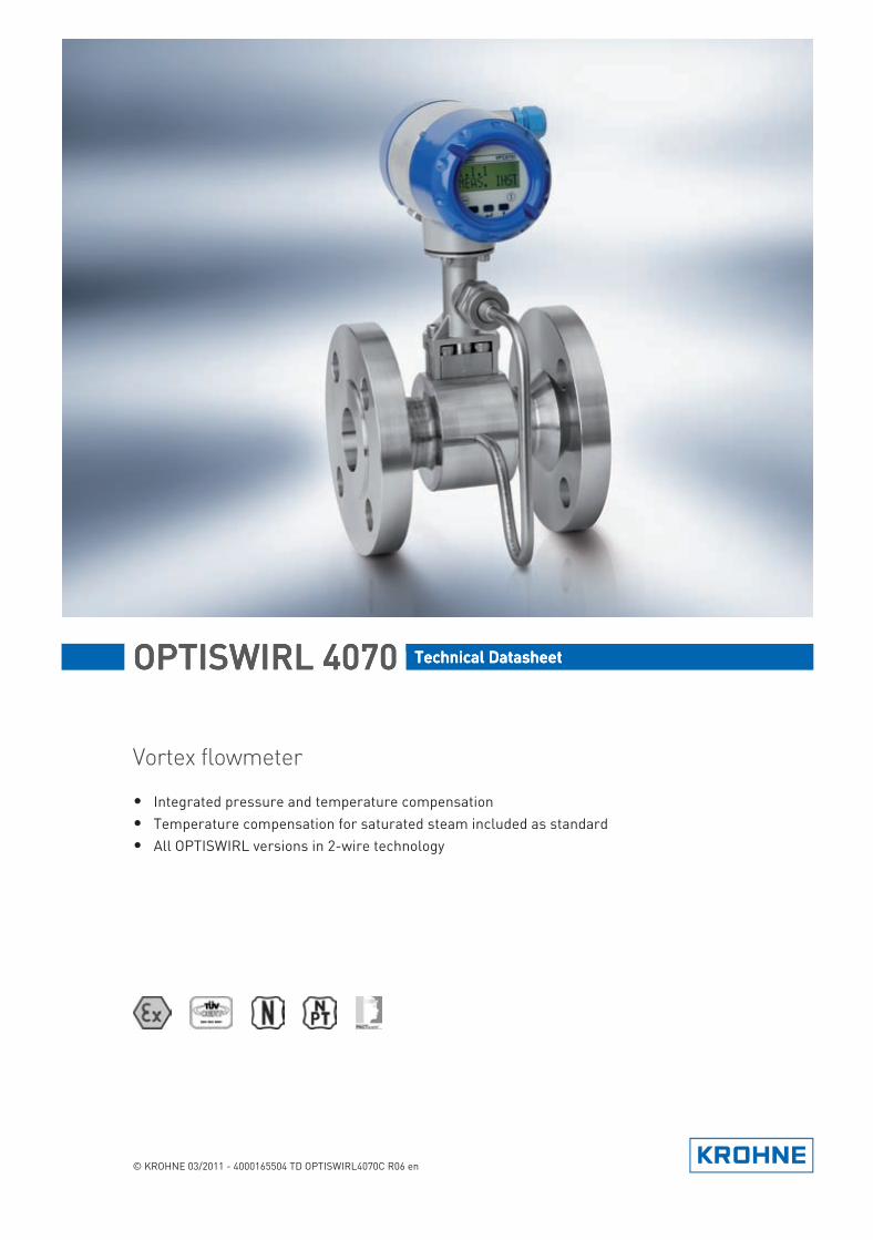
Vortex flowmeter
• Integrated pressure and temperature compensation• Temperature compensation for saturated steam included as standard• All OPTISWIRL versions in 2-wire technology
© KROHNE 03/2011 - 4000165504 TD OPTISWIRL4070C R06 en
TD_OPTISWIRL4070C_R06_en_165504_PRT.book Page 1 Thursday, March 24, 2011 7:05 AM
CONTENTS
2 www.krohne.com 03/2011 - 4000165504 TD OPTISWIRL4070C R06 en
OPTISWIRL 4070
1 Product features 3
1.1 The all-in-one solution..................................................................................................... 31.2 Options and variants......................................................................................................... 51.3 Functional principle.......................................................................................................... 8
2 Technical data 9
2.1 Technical data................................................................................................................... 92.2 Dimensions and weights ................................................................................................ 12
2.2.1 Flange versions..................................................................................................................... 122.2.2 Sandwich version .................................................................................................................. 152.2.3 Dimensions remote version.................................................................................................. 17
2.3 Flow tables ..................................................................................................................... 18
3 Installation 21
3.1 Intended use ................................................................................................................... 213.2 Installation conditions .................................................................................................... 22
3.2.1 Measurement of liquids ........................................................................................................ 233.2.2 Measurement of vapours and gases .................................................................................... 253.2.3 Heat insulation ...................................................................................................................... 26
3.3 Inlet and outlet runs ....................................................................................................... 273.3.1 Minimum inlet runs............................................................................................................... 273.3.2 Minimum outlet runs ............................................................................................................ 283.3.3 Flow straightener.................................................................................................................. 28
4 Electrical connections 29
4.1 Connecting the signal converter .................................................................................... 294.2 Electrical connection of current and pulse output ........................................................ 304.3 Remote version connection............................................................................................ 31
5 Order form 32
6 Notes 33
TD_OPTISWIRL4070C_R06_en_165504_PRT.book Page 2 Thursday, March 24, 2011 7:05 AM
PRODUCT FEATURES 1
3
OPTISWIRL 4070
www.krohne.com03/2011 - 4000165504 TD OPTISWIRL4070C R06 en
Product features
1.1 The all-in-one solution
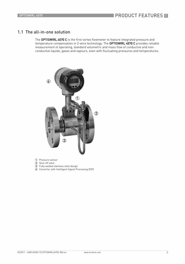
The OPTISWIRL 4070 COPTISWIRL 4070 COPTISWIRL 4070 COPTISWIRL 4070 C is the first vortex flowmeter to feature integrated pressure and temperature compensation in 2-wire technology. The OPTISWIRL 4070 COPTISWIRL 4070 COPTISWIRL 4070 COPTISWIRL 4070 C provides reliable measurement of operating, standard volumetric and mass flow of conductive and non-conductive liquids, gases and vapours, even with fluctuating pressures and temperatures.
1 Pressure sensor2 Shut-off valve3 Fully welded stainless steel design4 Converter with Intelligent Signal Processing [ISP]
TD_OPTISWIRL4070C_R06_en_165504_PRT.book Page 3 Thursday, March 24, 2011 7:05 AM
1 PRODUCT FEATURES
4
OPTISWIRL 4070
www.krohne.com 03/2011 - 4000165504 TD OPTISWIRL4070C R06 en
Highlights• 2-wire device with integrated pressure and temperature compensation• Non-wearing, fully welded stainless steel construction with high corrosion, pressure and
temperature resistance• Optimal process reliability thanks to Intelligent Signal Processing (ISP) - stable readings,
free of external perturbations• Ready to use immediately thanks to plug & play• Maintenance-free measuring sensor design• PACTware available at no extra cost• Pressure and temperature available via HART
Industries• Chemicals• Oil & Gas• Power plants• Food & Beverage• Pharmaceuticals• Iron, Steel and Metals• Paper and pulp• Water• Automobile industry
Applications• Vapour and saturated steam measurement• Steam boiler monitoring• Monitoring of compressor output• Measurement of consumption in compressed air systems• Measurement of consumption of industrial gases• SIP and CIP processes in the food, beverage and pharmaceutical industries• Measurement of conductive and non-conductive liquids
TD_OPTISWIRL4070C_R06_en_165504_PRT.book Page 4 Thursday, March 24, 2011 7:05 AM
PRODUCT FEATURES 1
5
OPTISWIRL 4070
www.krohne.com03/2011 - 4000165504 TD OPTISWIRL4070C R06 en
1.2 Options and variants
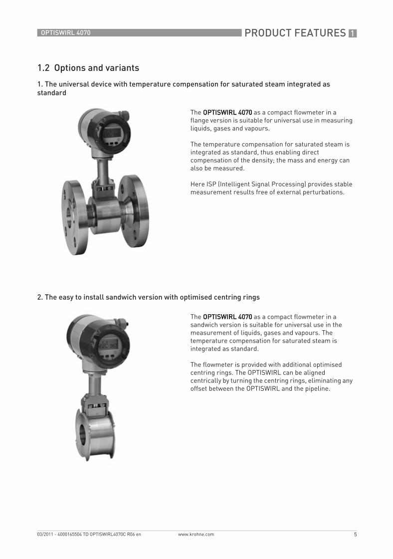
1. The universal device with temperature compensation for saturated steam integrated as standard
2. The easy to install sandwich version with optimised centring rings
The OPTISWIRL 4070OPTISWIRL 4070OPTISWIRL 4070OPTISWIRL 4070 as a compact flowmeter in a flange version is suitable for universal use in measuring liquids, gases and vapours.
The temperature compensation for saturated steam is integrated as standard, thus enabling direct compensation of the density; the mass and energy can also be measured.
Here ISP (Intelligent Signal Processing) provides stable measurement results free of external perturbations.
The OPTISWIRL 4070OPTISWIRL 4070OPTISWIRL 4070OPTISWIRL 4070 as a compact flowmeter in a sandwich version is suitable for universal use in the measurement of liquids, gases and vapours. The temperature compensation for saturated steam is integrated as standard.
The flowmeter is provided with additional optimised centring rings. The OPTISWIRL can be aligned centrically by turning the centring rings, eliminating any offset between the OPTISWIRL and the pipeline.
TD_OPTISWIRL4070C_R06_en_165504_PRT.book Page 5 Thursday, March 24, 2011 7:05 AM
1 PRODUCT FEATURES
6
OPTISWIRL 4070
www.krohne.com 03/2011 - 4000165504 TD OPTISWIRL4070C R06 en
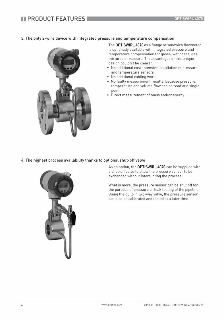
3. The only 2-wire device with integrated pressure and temperature compensation
4. The highest process availability thanks to optional shut-off valve
The OPTISWIRL 4070OPTISWIRL 4070OPTISWIRL 4070OPTISWIRL 4070 as a flange or sandwich flowmeter is optionally available with integrated pressure and temperature compensation for gases, wet gases, gas mixtures or vapours. The advantages of this unique design couldn't be clearer:
• No additional cost-intensive installation of pressure and temperature sensors
• No additional cabling work• No faulty measurement results, because pressure,
temperature and volume flow can be read at a single point
• Direct measurement of mass and/or energy
As an option, the OPTISWIRL 4070OPTISWIRL 4070OPTISWIRL 4070OPTISWIRL 4070 can be supplied with a shut-off valve to allow the pressure sensor to be exchanged without interrupting the process.
What is more, the pressure sensor can be shut off for the purpose of pressure or leak testing of the pipeline.Using the built-in two-way valve, the pressure sensor can also be calibrated and tested at a later time.
TD_OPTISWIRL4070C_R06_en_165504_PRT.book Page 6 Thursday, March 24, 2011 7:05 AM
PRODUCT FEATURES 1
7
OPTISWIRL 4070
www.krohne.com03/2011 - 4000165504 TD OPTISWIRL4070C R06 en
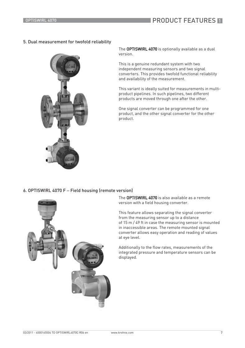
5. Dual measurement for twofold reliability
6. OPTISWIRL 4070 F – Field housing (remote version)
The OPTISWIRL 4070OPTISWIRL 4070OPTISWIRL 4070OPTISWIRL 4070 is optionally available as a dual version.
This is a genuine redundant system with two independent measuring sensors and two signal converters. This provides twofold functional reliability and availability of the measurement.
This variant is ideally suited for measurements in multi-product pipelines. In such pipelines, two different products are moved through one after the other.
One signal converter can be programmed for one product, and the other signal converter for the other product.
The OPTISWIRL 4070OPTISWIRL 4070OPTISWIRL 4070OPTISWIRL 4070 is also available as a remote version with a field housing converter.
This feature allows separating the signal converter from the measuring sensor up to a distanceof 15 m / 49 ft in case the measuring sensor is mounted in inaccessible areas. The remote mounted signal converter allows easy operation and reading of values at eye level.
Additionally to the flow rates, measurements of the integrated pressure and temperature sensors can be displayed.
TD_OPTISWIRL4070C_R06_en_165504_PRT.book Page 7 Thursday, March 24, 2011 7:05 AM
1 PRODUCT FEATURES
8
OPTISWIRL 4070
www.krohne.com 03/2011 - 4000165504 TD OPTISWIRL4070C R06 en
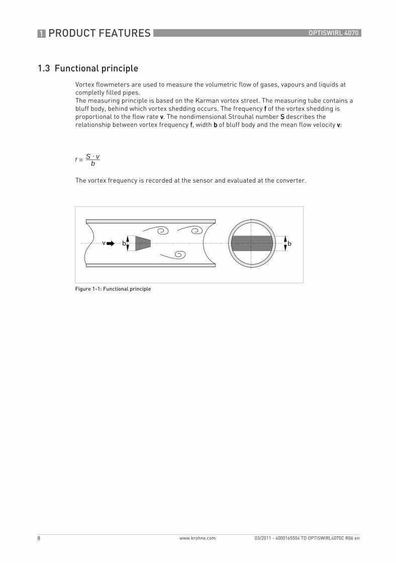
1.3 Functional principle
Vortex flowmeters are used to measure the volumetric flow of gases, vapours and liquids at completly filled pipes.The measuring principle is based on the Karman vortex street. The measuring tube contains a bluff body, behind which vortex shedding occurs. The frequency ffff of the vortex shedding is proportional to the flow rate vvvv. The nondimensional Strouhal number SSSS describes the relationship between vortex frequency ffff, width bbbb of bluff body and the mean flow velocity vvvv:
The vortex frequency is recorded at the sensor and evaluated at the converter.
Figure 1-1: Functional principle
=f S . vb
TD_OPTISWIRL4070C_R06_en_165504_PRT.book Page 8 Thursday, March 24, 2011 7:05 AM
TECHNICAL DATA 2
9
OPTISWIRL 4070
www.krohne.com03/2011 - 4000165504 TD OPTISWIRL4070C R06 en
Technical data
2.1 Technical data
• The following data is provided for general applications. If you require data that is more relevant to your specific application, please contact us or your local representative.
• Additional information (certificates, special tools, software,...) and complete product documentation can be downloaded free of charge from the website (Download Center).
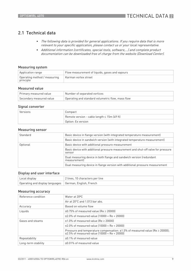
Measuring systemApplication range Flow measurement of liquids, gases and vapours
Operating method / measuring principle
Karman vortex street
Measured valuePrimary measured value Number of separated vortices
Secondary measured value Operating and standard volumetric flow, mass flow
Signal converterVersions Compact
Remote version - cable length ≤ 15m (49 ft)
Option: Ex version
Measuring sensorStandard Basic device in flange version (with integrated temperature measurement)
Basic device in sandwich version (with integrated temperature measurement)
Optional Basic device with additional pressure measurement
Basic device with additional pressure measurement and shut-off valve for pressure sensor
Dual measuring device in both flange and sandwich version (redundant measurement)
Dual measuring device in flange version with additional pressure measurement
Display and user interfaceLocal display 2 lines, 10 characters per line
Operating and display languages German, English, French
Measuring accuracyReference condition Water at 20ºC
Air at 20°C and 1.013 bar abs.
Accuracy Based on volume flow
Liquids ±0.75% of measured value (Re ≥ 20000)
±2.0% of measured value (10000 < Re < 20000)
Gases and steams ±1.0% of measured value (Re ≥ 20000)
±2.0% of measured value (10000 < Re < 20000)
Pressure and temperature compensation: ±1.5% of measured value (Re ≥ 20000); ±2.5% of measured value (10000 < Re < 20000)
Repeatability ±0.1% of measured value
Long-term stability ±0.01% of measured value
TD_OPTISWIRL4070C_R06_en_165504_PRT.book Page 9 Thursday, March 24, 2011 7:05 AM
2 TECHNICAL DATA
10
OPTISWIRL 4070
www.krohne.com 03/2011 - 4000165504 TD OPTISWIRL4070C R06 en
Operating conditions
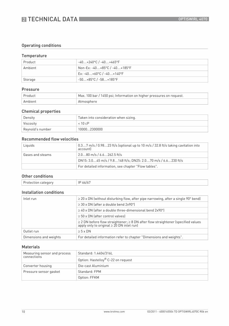
TemperatureProduct -40…+240°C / -40…+465°F
Ambient Non-Ex: -40…+85°C / -40…+185°F
Ex: -40…+60°C / -40…+140°F
Storage -50…+85°C / -58…+185°F
PressureProduct Max. 100 bar / 1450 psi; Information on higher pressures on request.
Ambient Atmosphere
Chemical propertiesDensity Taken into consideration when sizing.
Viscosity < 10 cP
Reynold's number 10000...2300000
Recommended flow velocitiesLiquids 0.3…7 m/s / 0.98…23 ft/s (optional up to 10 m/s / 32.8 ft/s taking cavitation into
account)
Gases and steams 2.0…80 m/s / 6.6…262.5 ft/s
DN15: 3.0…45 m/s / 9.8…148 ft/s; DN25: 2.0…70 m/s / 6.6…230 ft/s
For detailed information, see chapter "Flow tables".
Other conditionsProtection category IP 66/67
Installation conditionsInlet run ≥ 20 x DN (without disturbing flow, after pipe narrowing, after a single 90° bend)
≥ 30 x DN (after a double bend 2x90°)
≥ 40 x DN (after a double three-dimensional bend 2x90°)
≥ 50 x DN (after control valves)
≥ 2 DN before flow straightener; ≥ 8 DN after flow straightener (specified values apply only to original ≥ 20 DN inlet run)
Outlet run ≥ 5 x DN
Dimensions and weights For detailed information refer to chapter "Dimensions and weights".
MaterialsMeasuring sensor and process connections
Standard: 1.4404/316L
Option: Hastelloy® C-22 on request
Converter housing Die-cast Aluminium
Pressure sensor gasket Standard: FPM
Option: FFKM
TD_OPTISWIRL4070C_R06_en_165504_PRT.book Page 10 Thursday, March 24, 2011 7:05 AM
TECHNICAL DATA 2
11
OPTISWIRL 4070
www.krohne.com03/2011 - 4000165504 TD OPTISWIRL4070C R06 en
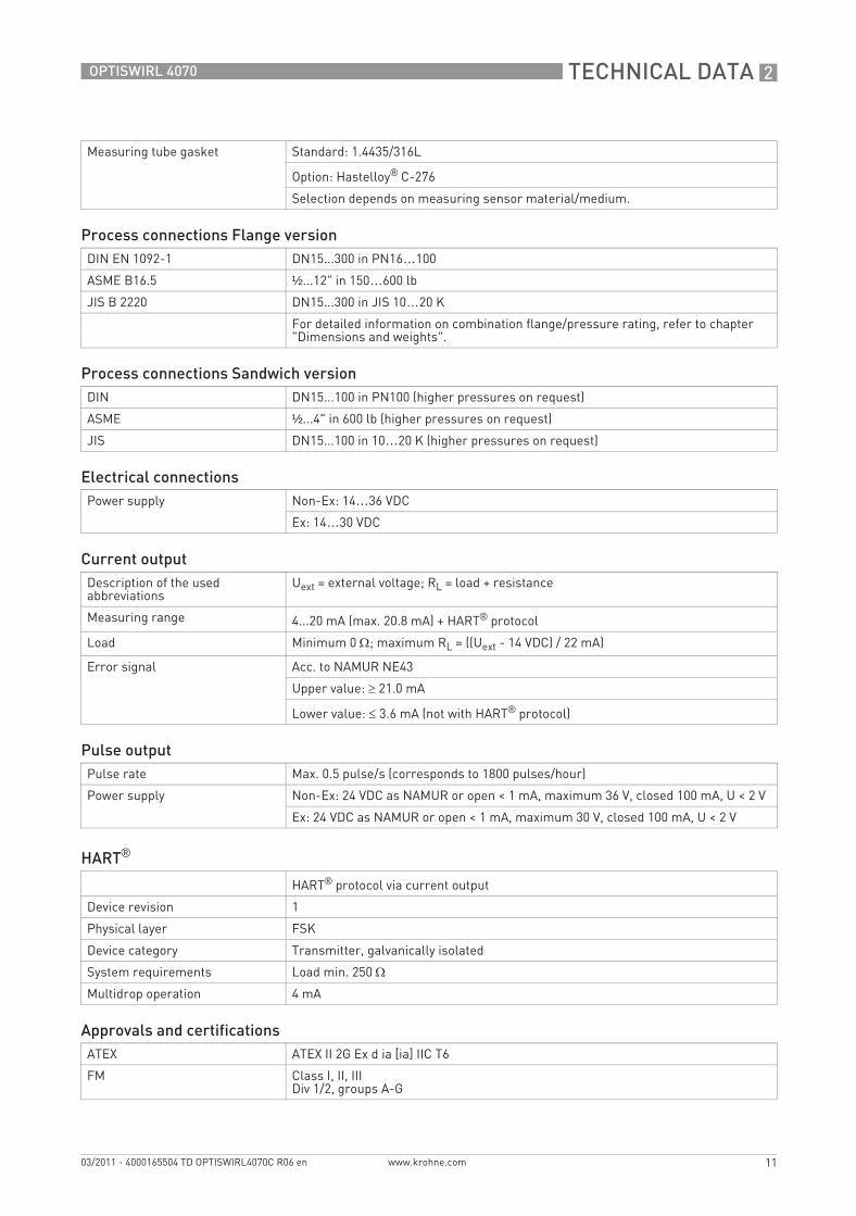
Measuring tube gasket Standard: 1.4435/316L
Option: Hastelloy® C-276
Selection depends on measuring sensor material/medium.
Process connections Flange versionDIN EN 1092-1 DN15...300 in PN16…100
ASME B16.5 ½...12" in 150…600 lb
JIS B 2220 DN15...300 in JIS 10…20 K
For detailed information on combination flange/pressure rating, refer to chapter "Dimensions and weights".
Process connections Sandwich versionDIN DN15...100 in PN100 (higher pressures on request)
ASME ½...4" in 600 lb (higher pressures on request)
JIS DN15...100 in 10…20 K (higher pressures on request)
Electrical connectionsPower supply Non-Ex: 14…36 VDC
Ex: 14…30 VDC
Current outputDescription of the used abbreviations
Uext = external voltage; RL = load + resistance
Measuring range 4...20 mA (max. 20.8 mA) + HART® protocol
Load Minimum 0 Ω; maximum RL = ((Uext - 14 VDC) / 22 mA)
Error signal Acc. to NAMUR NE43
Upper value: ≥ 21.0 mA
Lower value: ≤ 3.6 mA (not with HART® protocol)
Pulse outputPulse rate Max. 0.5 pulse/s (corresponds to 1800 pulses/hour)
Power supply Non-Ex: 24 VDC as NAMUR or open < 1 mA, maximum 36 V, closed 100 mA, U < 2 V
Ex: 24 VDC as NAMUR or open < 1 mA, maximum 30 V, closed 100 mA, U < 2 V
HART®
HART® protocol via current output
Device revision 1
Physical layer FSK
Device category Transmitter, galvanically isolated
System requirements Load min. 250 Ω
Multidrop operation 4 mA
Approvals and certificationsATEX ATEX II 2G Ex d ia [ia] IIC T6
FM Class I, II, IIIDiv 1/2, groups A-G
TD_OPTISWIRL4070C_R06_en_165504_PRT.book Page 11 Thursday, March 24, 2011 7:05 AM
2 TECHNICAL DATA
12
OPTISWIRL 4070
www.krohne.com 03/2011 - 4000165504 TD OPTISWIRL4070C R06 en
2.2 Dimensions and weights
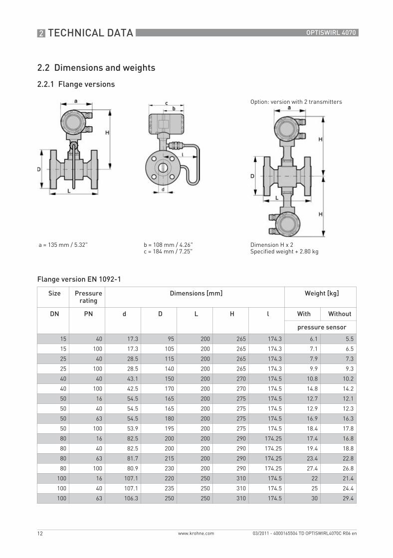
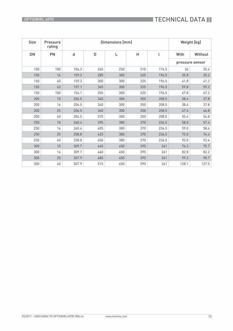
2.2.1 Flange versions
Flange version EN 1092-1
Option: version with 2 transmitters
a = 135 mm / 5.32" b = 108 mm / 4.26"c = 184 mm / 7.25"
Dimension H x 2Specified weight + 2.80 kg
Size Pressure rating
Dimensions [mm] Weight [kg]
DN PN d D L H l With Without
pressure sensor
15 40 17.3 95 200 265 174.3 6.1 5.5
15 100 17.3 105 200 265 174.3 7.1 6.5
25 40 28.5 115 200 265 174.3 7.9 7.3
25 100 28.5 140 200 265 174.3 9.9 9.3
40 40 43.1 150 200 270 174.5 10.8 10.2
40 100 42.5 170 200 270 174.5 14.8 14.2
50 16 54.5 165 200 275 174.5 12.7 12.1
50 40 54.5 165 200 275 174.5 12.9 12.3
50 63 54.5 180 200 275 174.5 16.9 16.3
50 100 53.9 195 200 275 174.5 18.4 17.8
80 16 82.5 200 200 290 174.25 17.4 16.8
80 40 82.5 200 200 290 174.25 19.4 18.8
80 63 81.7 215 200 290 174.25 23.4 22.8
80 100 80.9 230 200 290 174.25 27.4 26.8
100 16 107.1 220 250 310 174.5 22 21.4
100 40 107.1 235 250 310 174.5 25 24.4
100 63 106.3 250 250 310 174.5 30 29.4
TD_OPTISWIRL4070C_R06_en_165504_PRT.book Page 12 Thursday, March 24, 2011 7:05 AM
TECHNICAL DATA 2
13
OPTISWIRL 4070
www.krohne.com03/2011 - 4000165504 TD OPTISWIRL4070C R06 en
100 100 104.3 265 250 310 174.5 36 35.4
150 16 159.3 285 300 325 196.5 35.8 35.2
150 40 159.3 300 300 325 196.5 41.8 41.2
150 63 157.1 345 300 325 196.5 59.8 59.2
150 100 154.1 355 300 325 196.5 67.8 67.2
200 10 206.5 340 300 350 208.5 38.4 37.8
200 16 206.5 340 300 350 208.5 38.4 37.8
200 25 206.5 360 300 350 208.5 47.4 46.8
200 40 206.5 375 300 350 208.5 55.4 54.8
250 10 260.4 395 380 370 236.5 58.0 57.4
250 16 260.4 405 380 370 236.5 59.0 58.4
250 25 258.8 425 380 370 236.5 75.0 74.4
250 40 258.8 450 380 370 236.5 93.0 92.4
300 10 309.7 445 450 395 261 76.3 75.7
300 16 309.7 460 450 395 261 82.8 82.2
300 25 307.9 485 450 395 261 99.3 98.7
300 40 307.9 515 450 395 261 128.1 127.5
Size Pressure rating
Dimensions [mm] Weight [kg]
DN PN d D L H l With Without
pressure sensor
TD_OPTISWIRL4070C_R06_en_165504_PRT.book Page 13 Thursday, March 24, 2011 7:05 AM

2 TECHNICAL DATA
14
OPTISWIRL 4070
www.krohne.com 03/2011 - 4000165504 TD OPTISWIRL4070C R06 en
Flange version ASME B16.5
a = 135 mm / 5.32" b = 108 mm / 4.26" c = 184 mm / 7.25"
Size Pressure rating
Dimensions [mm / inches] Weight [kg / lb]
d D L H l With Without
NPS Class pressure sensor
½ 150 15.8 / 0.6 90 / 3.5 200 / 7.9 265 / 10.4 174.3 / 6.9 5.1 / 11.2 4.5 / 9.9
½ 300 15.8 / 0.6 95 / 3.7 200 / 7.9 265 / 10.4 174.3 / 6.9 5.5 / 12.1 4.9 / 10.8
½ 600 13.9 / 0.5 95 / 3.7 200 / 7.9 265 / 10.4 174.3 / 6.9 5.7 / 12.6 5.1 / 11.2
1 150 26.6 / 1.1 110 / 4.3 200 / 7.9 265 / 10.4 174.3 / 6.9 6.8 / 15.0 6.2 / 13.7
1 300 26.6 / 1.1 125 / 4.9 200 / 7.9 265 / 10.4 174.3 / 6.9 7.8 / 17.2 7.2 / 15.9
1 600 24.3 / 1.0 125 / 4.9 200 / 7.9 265 / 10.4 174.3 / 6.9 8.1 / 17.9 7.5 / 16.5
1½ 150 40.9 / 1.6 125 / 4.9 200 / 7.9 270 / 10.6 174.3 / 6.9 8.9 / 19.9 8.3 / 18.3
1½ 300 40.9 / 1.6 155 / 6.1 200 / 7.9 270 / 10.6 174.3 / 6.9 11 / 24.3 10.4 / 22.9
1½ 600 38.1 / 1.5 155 / 6.1 200 / 7.9 270 / 10.6 174.3 / 6.9 12 / 26.5 11.4 / 25.1
2 150 52.6 / 2.1 150 / 5.9 200 / 7.9 275 / 10.8 174.3 / 6.9 11.6 / 25.6 11 / 24.3
2 300 52.6 / 2.1 165 / 6.5 200 / 7.9 275 / 10.8 174.3 / 6.9 13 / 28.7 12.4 / 27.4
2 600 49.3 / 1.9 165 / 6.5 200 / 7.9 275 / 10.8 174.3 / 6.9 14.5 / 32.0 13.9 / 30.6
3 150 78 / 3.1 190 / 7.5 200 / 7.9 290 / 11.4 174.5 / 6.9 20.4 / 45.0 19.8 / 43.7
3 300 78 / 3.1 210 / 8.3 200 / 7.9 290 / 11.4 174.5 / 6.9 23.4 / 51.6 22.8 / 50.2
3 600 73.7 / 2.9 210 / 8.3 200 / 7.9 290 / 11.4 174.5 / 6.9 24.4 / 52.8 23.8 / 52.5
4 150 102.4 / 4.0 230 / 9.1 250 / 9.8 310 / 12.2 176.5 / 7.0 24 / 52.9 23.4 / 51.6
4 300 102.4 / 4.0 255 / 10.0 250 / 9.8 310 / 12.2 176.5 / 7.0 32 / 70.6 31.4 / 69.2
4 600 97.2 / 3.8 275 / 10.8 250 / 9.8 310 / 12.2 176.5 / 7.0 41 / 90.4 40.4 / 89.1
6 150 154.2 / 6.1 280 / 11.0 300 / 11.8 325 / 12.8 196.5 / 7.7 36.8 / 81.1 36.2 / 79.8
6 300 154.2 / 6.1 320 / 12.6 300 / 11.8 325 / 12.8 196.5 / 7.7 51.8 / 114.2 51.2 / 112.9
6 600 146.3 / 5.8 355 / 14.0 300 / 11.8 325 / 12.8 196.5 / 7.7 76.8 / 169.3 46.2 / 101.9
8 150 202.7 / 8.0 345 / 13.6 300 / 11.8 350 / 13.8 208.5 / 8.2 50.6 / 146.4 50.0 / 145.7
8 300 202.7 / 8.0 380 / 15.0 300 / 11.8 350 / 13.8 208.5 / 8.2 75.4 / 190.4 74.8 / 189.7
10 150 254.5 / 10.0 405 / 15.5 380 / 15.0 370 / 14.6 236.5 / 9.3 75.0 / 197.1 74.4 / 195.8
10 300 254.5 / 10.0 455 / 17.9 380 / 15.0 370 / 14.6 236.5 / 9.3 107.0 / 252.2 106.4 / 239.9
12 150 304.8 / 1 485 / 19.1 450 / 17.7 395 / 15.6 261 / 10.3 106.9 / 318.3 106.3 / 317.0
12 300 304.8 / 1 520 / 20.5 450 / 17.7 395 / 15.6 261 / 10.3 151.9 / 415.4 151.3 / 414.0
TD_OPTISWIRL4070C_R06_en_165504_PRT.book Page 14 Thursday, March 24, 2011 7:05 AM
TECHNICAL DATA 2
15
OPTISWIRL 4070
www.krohne.com03/2011 - 4000165504 TD OPTISWIRL4070C R06 en
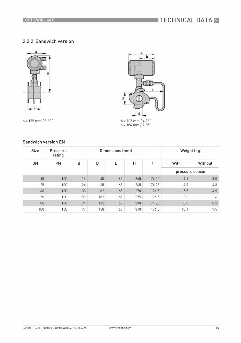
2.2.2 Sandwich version
Sandwich version EN
a = 135 mm / 5.32" b = 108 mm / 4.26"c = 184 mm / 7.25"
Size Pressure rating
Dimensions [mm] Weight [kg]
DN PN d D L H l With Without
pressure sensor
15 100 16 45 65 265 174.25 4.1 3.5
25 100 24 65 65 265 174.25 4.9 4.3
40 100 38 82 65 270 174.5 5.5 4.9
50 100 50 102 65 275 174.5 6.6 6
80 100 74 135 65 290 174.25 8.8 8.2
100 100 97 158 65 310 176.5 10.1 9.5
TD_OPTISWIRL4070C_R06_en_165504_PRT.book Page 15 Thursday, March 24, 2011 7:05 AM
2 TECHNICAL DATA
16
OPTISWIRL 4070
www.krohne.com 03/2011 - 4000165504 TD OPTISWIRL4070C R06 en
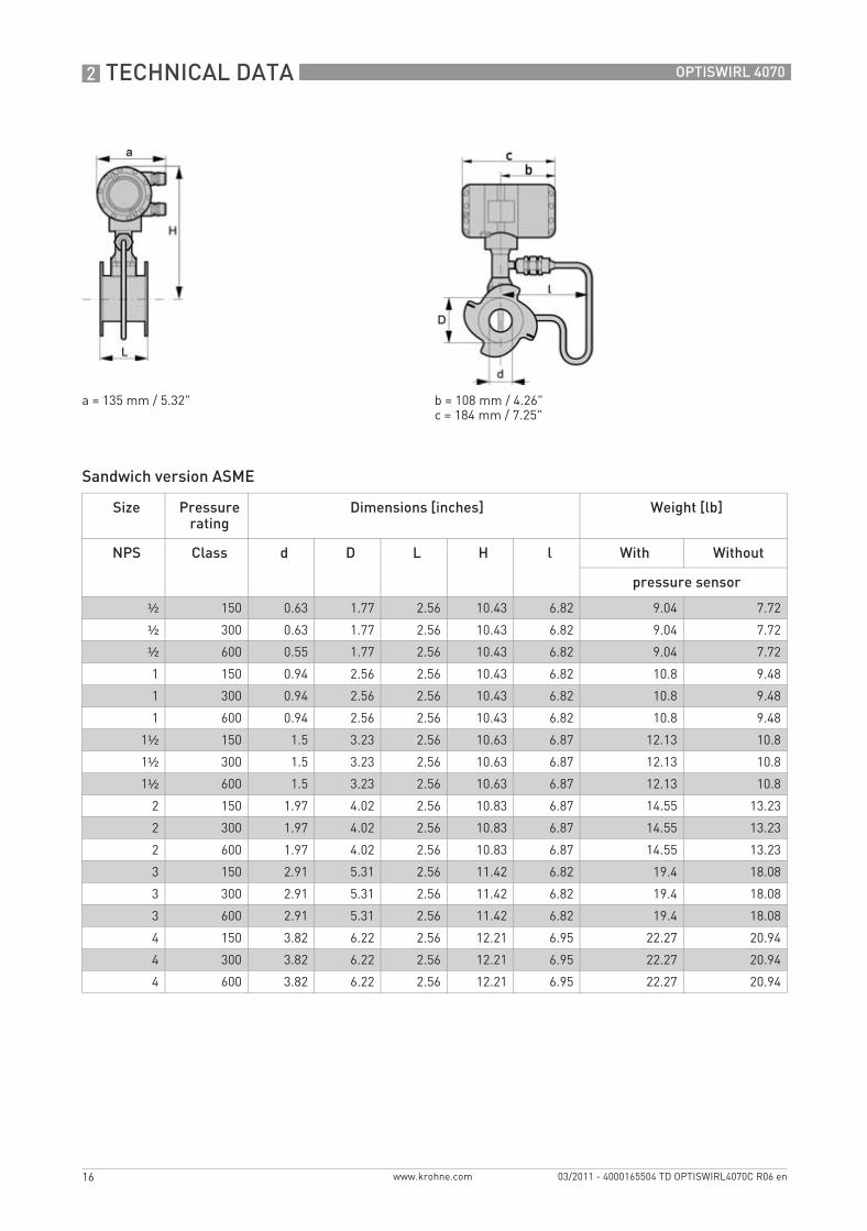
Sandwich version ASME
a = 135 mm / 5.32" b = 108 mm / 4.26"c = 184 mm / 7.25"
Size Pressure rating
Dimensions [inches] Weight [lb]
NPS Class d D L H l With Without
pressure sensor
½ 150 0.63 1.77 2.56 10.43 6.82 9.04 7.72
½ 300 0.63 1.77 2.56 10.43 6.82 9.04 7.72
½ 600 0.55 1.77 2.56 10.43 6.82 9.04 7.72
1 150 0.94 2.56 2.56 10.43 6.82 10.8 9.48
1 300 0.94 2.56 2.56 10.43 6.82 10.8 9.48
1 600 0.94 2.56 2.56 10.43 6.82 10.8 9.48
1½ 150 1.5 3.23 2.56 10.63 6.87 12.13 10.8
1½ 300 1.5 3.23 2.56 10.63 6.87 12.13 10.8
1½ 600 1.5 3.23 2.56 10.63 6.87 12.13 10.8
2 150 1.97 4.02 2.56 10.83 6.87 14.55 13.23
2 300 1.97 4.02 2.56 10.83 6.87 14.55 13.23
2 600 1.97 4.02 2.56 10.83 6.87 14.55 13.23
3 150 2.91 5.31 2.56 11.42 6.82 19.4 18.08
3 300 2.91 5.31 2.56 11.42 6.82 19.4 18.08
3 600 2.91 5.31 2.56 11.42 6.82 19.4 18.08
4 150 3.82 6.22 2.56 12.21 6.95 22.27 20.94
4 300 3.82 6.22 2.56 12.21 6.95 22.27 20.94
4 600 3.82 6.22 2.56 12.21 6.95 22.27 20.94
TD_OPTISWIRL4070C_R06_en_165504_PRT.book Page 16 Thursday, March 24, 2011 7:05 AM
TECHNICAL DATA 2
17
OPTISWIRL 4070
www.krohne.com03/2011 - 4000165504 TD OPTISWIRL4070C R06 en
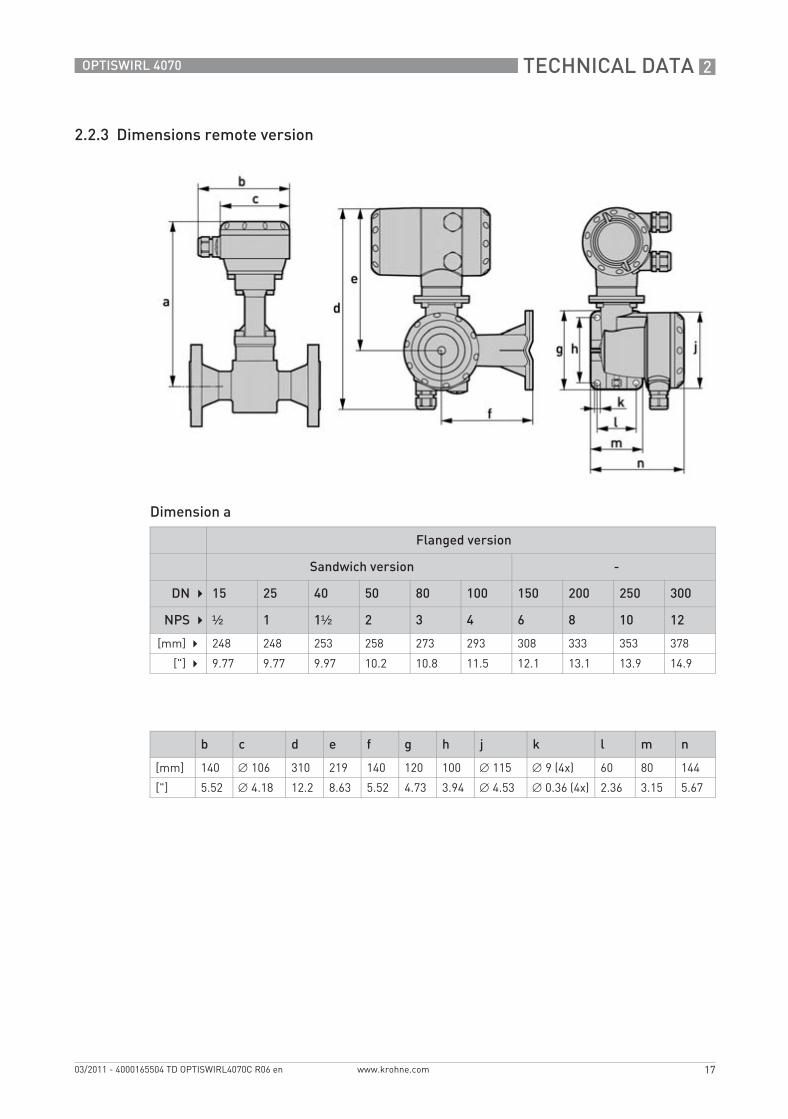
2.2.3 Dimensions remote version
Dimension a
Flanged version
Sandwich version -
DN 15 25 40 50 80 100 150 200 250 300
NPS ½ 1 1½ 2 3 4 6 8 10 12
[mm] 248 248 253 258 273 293 308 333 353 378
["] 9.77 9.77 9.97 10.2 10.8 11.5 12.1 13.1 13.9 14.9
b c d e f g h j k l m n
[mm] 140 ∅ 106 310 219 140 120 100 ∅ 115 ∅ 9 (4x) 60 80 144
["] 5.52 ∅ 4.18 12.2 8.63 5.52 4.73 3.94 ∅ 4.53 ∅ 0.36 (4x) 2.36 3.15 5.67
TD_OPTISWIRL4070C_R06_en_165504_PRT.book Page 17 Thursday, March 24, 2011 7:05 AM
2 TECHNICAL DATA
18
OPTISWIRL 4070
www.krohne.com 03/2011 - 4000165504 TD OPTISWIRL4070C R06 en
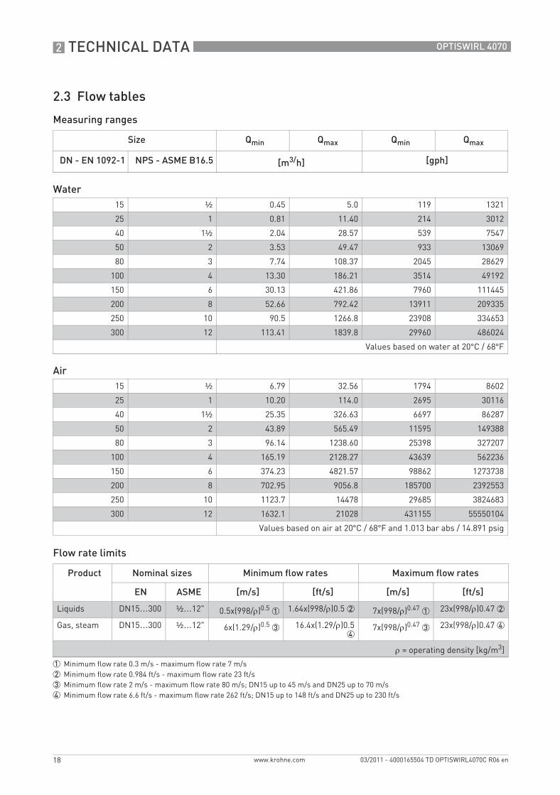
2.3 Flow tables
Measuring ranges
Flow rate limits
Size Qmin Qmax Qmin Qmax
DN - EN 1092-1 NPS - ASME B16.5 [m3/h] [gph]
Water15 ½ 0.45 5.0 119 1321
25 1 0.81 11.40 214 3012
40 1½ 2.04 28.57 539 7547
50 2 3.53 49.47 933 13069
80 3 7.74 108.37 2045 28629
100 4 13.30 186.21 3514 49192
150 6 30.13 421.86 7960 111445
200 8 52.66 792.42 13911 209335
250 10 90.5 1266.8 23908 334653
300 12 113.41 1839.8 29960 486024
Values based on water at 20°C / 68°F
Air15 ½ 6.79 32.56 1794 8602
25 1 10.20 114.0 2695 30116
40 1½ 25.35 326.63 6697 86287
50 2 43.89 565.49 11595 149388
80 3 96.14 1238.60 25398 327207
100 4 165.19 2128.27 43639 562236
150 6 374.23 4821.57 98862 1273738
200 8 702.95 9056.8 185700 2392553
250 10 1123.7 14478 29685 3824683
300 12 1632.1 21028 431155 55550104
Values based on air at 20°C / 68°F and 1.013 bar abs / 14.891 psig
Product Nominal sizes Minimum flow rates Maximum flow rates
EN ASME [m/s] [ft/s] [m/s] [ft/s]
Liquids DN15…300 ½…12" 0.5x(998/ρ)0.5 1 1.64x(998/ρ)0.5 2 7x(998/ρ)0.47 1 23x(998/ρ)0.47 2
Gas, steam DN15…300 ½…12" 6x(1.29/ρ)0.5 3 16.4x(1.29/ρ)0.54
7x(998/ρ)0.47 3 23x(998/ρ)0.47 4
ρ = operating density [kg/m3]
1 Minimum flow rate 0.3 m/s - maximum flow rate 7 m/s2 Minimum flow rate 0.984 ft/s - maximum flow rate 23 ft/s3 Minimum flow rate 2 m/s - maximum flow rate 80 m/s; DN15 up to 45 m/s and DN25 up to 70 m/s4 Minimum flow rate 6.6 ft/s - maximum flow rate 262 ft/s; DN15 up to 148 ft/s and DN25 up to 230 ft/s
TD_OPTISWIRL4070C_R06_en_165504_PRT.book Page 18 Thursday, March 24, 2011 7:05 AM
TECHNICAL DATA 2
19
OPTISWIRL 4070
www.krohne.com03/2011 - 4000165504 TD OPTISWIRL4070C R06 en
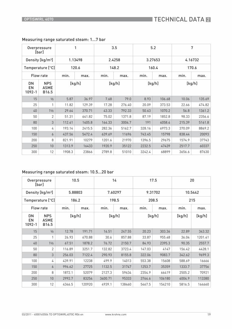
Measuring range saturated steam: 1...7 bar
Measuring range saturated steam: 10.5...20 bar
Overpressure [bar]
1 3.5 5.2 7
Density [kg/m³] 1.13498 2.4258 3.27653 4.16732
Temperature [°C] 120.6 148.2 160.4 170.6
Flow rate min. max. min. max. min. max. min. max.
DNEN
1092-1
NPSASME B16.5
[kg/h] [kg/h] [kg/h] [kg/h]
15 ½ 5.87 36.97 7.68 79.0 8.93 106.68 10.06 135.69
25 1 11.82 129.39 17.28 276.40 20.09 373.53 22.66 474.82
40 1½ 29.64 370.71 43.33 792.33 50.63 1070.2 56.8 1361.2
50 2 51.31 641.82 75.02 1371.8 87.19 1852.8 98.33 2356.6
80 3 112.41 1405.8 164.33 3004.7 191 4058.4 215.39 5161.8
100 4 193.14 2415.5 282.36 5162.7 328.16 6973.3 370.09 8869.2
150 6 437.56 5472.4 639.69 11696 743.45 15798 838.44 20093
200 8 821.91 10279 1201.6 21970 1396.5 29675 1574.9 37743
250 10 1313.9 16433 1920.9 35122 2232.5 47439 2517.7 60337
300 12 1908.3 23866 2789.8 51010 3242.4 68899 3656.6 87630
Overpressure [bar]
10.5 14 17.5 20
Density [kg/m³] 5.88803 7.60297 9.31702 10.5442
Temperature [°C] 186.2 198.5 208.5 215
Flow rate min. max. min. max. min. max. min. max.
DNEN
1092-1
NPSASME B16.5
[kg/h] [kg/h] [kg/h] [kg/h] [kg/h]
15 ½ 12.78 191.71 16.51 247.55 20.23 303.36 22.89 343.32
25 1 26.93 670.88 30.6 857.88 33.87 955.48 36.04 1201.41
40 1½ 67.51 1878.2 76.72 2150.7 84.93 2395.3 90.35 2557.7
50 2 116.89 3251.7 132.82 3723.4 147.03 4147 156.42 4428.1
80 3 256.03 7122.4 290.93 8155.8 322.06 9083.7 342.62 9699.3
100 4 439.91 12238 499.9 14013 553.38 15608 588.69 16666
150 6 996.62 27725 1132.5 31747 1253.7 35359 1333.7 37756
200 8 1872.1 52079 2127.3 59634 2354.9 66419 2505.2 70921
250 10 2992.7 83254 3400.71 95333 3764.6 106180 4004.9 113380
300 12 4346.5 120920 4939.1 138460 5467.5 154210 5816.5 164660
TD_OPTISWIRL4070C_R06_en_165504_PRT.book Page 19 Thursday, March 24, 2011 7:05 AM
2 TECHNICAL DATA
20
OPTISWIRL 4070
www.krohne.com 03/2011 - 4000165504 TD OPTISWIRL4070C R06 en
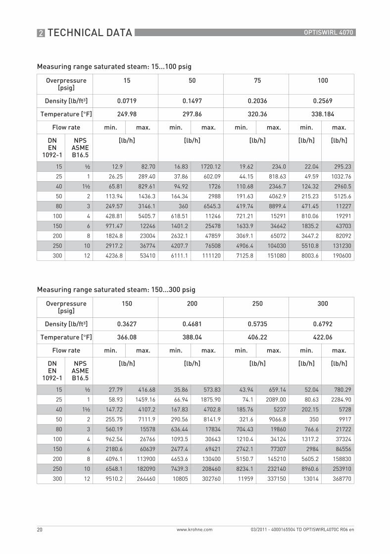
Measuring range saturated steam: 15...100 psig
Measuring range saturated steam: 150...300 psig
Overpressure [psig]
15 50 75 100
Density [lb/ft³] 0.0719 0.1497 0.2036 0.2569
Temperature [°F] 249.98 297.86 320.36 338.184
Flow rate min. max. min. max. min. max. min. max.
DNEN
1092-1
NPSASME B16.5
[lb/h] [lb/h] [lb/h] [lb/h] [lb/h]
15 ½ 12.9 82.70 16.83 1720.12 19.62 234.0 22.04 295.23
25 1 26.25 289.40 37.86 602.09 44.15 818.63 49.59 1032.76
40 1½ 65.81 829.61 94.92 1726 110.68 2346.7 124.32 2960.5
50 2 113.94 1436.3 164.34 2988 191.63 4062.9 215.23 5125.6
80 3 249.57 3146.1 360 6545.3 419.74 8899.4 471.45 11227
100 4 428.81 5405.7 618.51 11246 721.21 15291 810.06 19291
150 6 971.47 12246 1401.2 25478 1633.9 34642 1835.2 43703
200 8 1824.8 23004 2632.1 47859 3069.1 65072 3447.2 82092
250 10 2917.2 36774 4207.7 76508 4906.4 104030 5510.8 131230
300 12 4236.8 53410 6111.1 111120 7125.8 151080 8003.6 190600
Overpressure [psig]
150 200 250 300
Density [lb/ft³] 0.3627 0.4681 0.5735 0.6792
Temperature [°F] 366.08 388.04 406.22 422.06
Flow rate min. max. min. max. min. max. min. max.
DNEN
1092-1
NPSASME B16.5
[lb/h] [lb/h] [lb/h] [lb/h] [lb/h]
15 ½ 27.79 416.68 35.86 573.83 43.94 659.14 52.04 780.29
25 1 58.93 1459.16 66.94 1875.90 74.1 2089.00 80.63 2284.90
40 1½ 147.72 4107.2 167.83 4702.8 185.76 5237 202.15 5728
50 2 255.75 7111.9 290.56 8141.9 321.6 9066.8 350 9917
80 3 560.19 15578 636.44 17834 704.43 19860 766.6 21722
100 4 962.54 26766 1093.5 30643 1210.4 34124 1317.2 37324
150 6 2180.6 60639 2477.4 69421 2742.1 77307 2984 84556
200 8 4096.1 113900 4653.6 130400 5150.7 145210 5605.2 158830
250 10 6548.1 182090 7439.3 208460 8234.1 232140 8960.6 253910
300 12 9510.2 264460 10805 302760 11959 337150 13014 368770
TD_OPTISWIRL4070C_R06_en_165504_PRT.book Page 20 Thursday, March 24, 2011 7:05 AM
INSTALLATION 3
21
OPTISWIRL 4070
www.krohne.com03/2011 - 4000165504 TD OPTISWIRL4070C R06 en
Installation
3.1 Intended use
The vortex flowmeters are made to measure the flow of gases, vapours and liquids.
The devices are particularly suitable for the measurement of:• Clean liquids with low viscosity (< 10 cP)• Hydrocarbons with low viscosity (< 10 cP)• Water • Chemicals with low corrosiveness• Saturated steam• Superheated steam, including CIP and SIP applications in the food industry• Industrial gases
The devices are rated for the following flow velocities:• Liquids: 0.3...7 m/s / 1.0...23 ft/s• Gases and steam: 2.0...80 m/s / 6.6...262 ft/s
DN15: 3.0...45 m/s / 9.8...148 ft/s; DN25: 2.0...70 m/s / 6.6...230 ft/s
If the danger of waterhammers can occur in steam networks appropriate condensate separators have to be installed.Suitable measures must be taken to avoid water cavitation if it is a possible risk.
• The sensors are made from Stainless Steel 316 L (1.4404) or Hastelloy® C22.• In your project planning, please observe the data given in the corrosion tables.• The pressure-bearing parts have been designed and rated for stationary operation taking into
account the maximum pressure and temperature.• Observe the data indicated on the nameplate for PS, TS and PT (PED 97/23/EC).• External forces and moments, caused e.g. by pipe stresses, have not been taken into account.
Primarily, volumetric flow and temperature are measured, with pressure measurement as an option. From these parameters the measuring device calculates the mass flow or standard volumetric flow using pre-programmed density data and then exports the measured values via various communication interfaces.
Responsibility for the use of the measurement devices with regard to suitability, intended use and corrosion resistance of the used materials against the measured fluid lies solely with the operator.
TD_OPTISWIRL4070C_R06_en_165504_PRT.book Page 21 Thursday, March 24, 2011 7:05 AM
3 INSTALLATION
22
OPTISWIRL 4070
www.krohne.com 03/2011 - 4000165504 TD OPTISWIRL4070C R06 en
3.2 Installation conditions
For accurate volumetric flow measurement the measuring device needs a completely filled pipe and a fully developed flow profile. Please observe the instructions regarding inlet and outlet pipe runs as well as the installation position. In the event of vibrations on the piping, select the installation site so that the vibrations are at their lowest in a transverse direction to the flowmeter.
When installing the device in the piping, the following points must be observed:• Nominal diameter of connection pipe flange = nominal flange diameter of pipe!• Use flanges with smooth holes, e.g. welding neck flanges.• Align carefully the holes of the connecting flange and the flowmeter flange.• Check the compatibility of the gasket material with the process product.• Make sure that the gaskets are arranged concentrically. The flange gaskets must not project
into the pipe cross-section.• The flanges have to be concentric.• There must not be any pipe bends, valves, flaps or other internals in the immediate inlet run.• Devices in sandwich version may only be installed using a centering ring.• Never install the device directly behind piston compressors or rotary piston meters.• Do not lay signal cables directly next to cables for the power supply.
If the danger of waterhammers can occur in steam networks appropriate condensate separators have to be installed.Suitable measures must be taken to avoid water cavitation if it is a possible risk.
TD_OPTISWIRL4070C_R06_en_165504_PRT.book Page 22 Thursday, March 24, 2011 7:05 AM
INSTALLATION 3
23
OPTISWIRL 4070
www.krohne.com03/2011 - 4000165504 TD OPTISWIRL4070C R06 en
3.2.1 Measurement of liquids
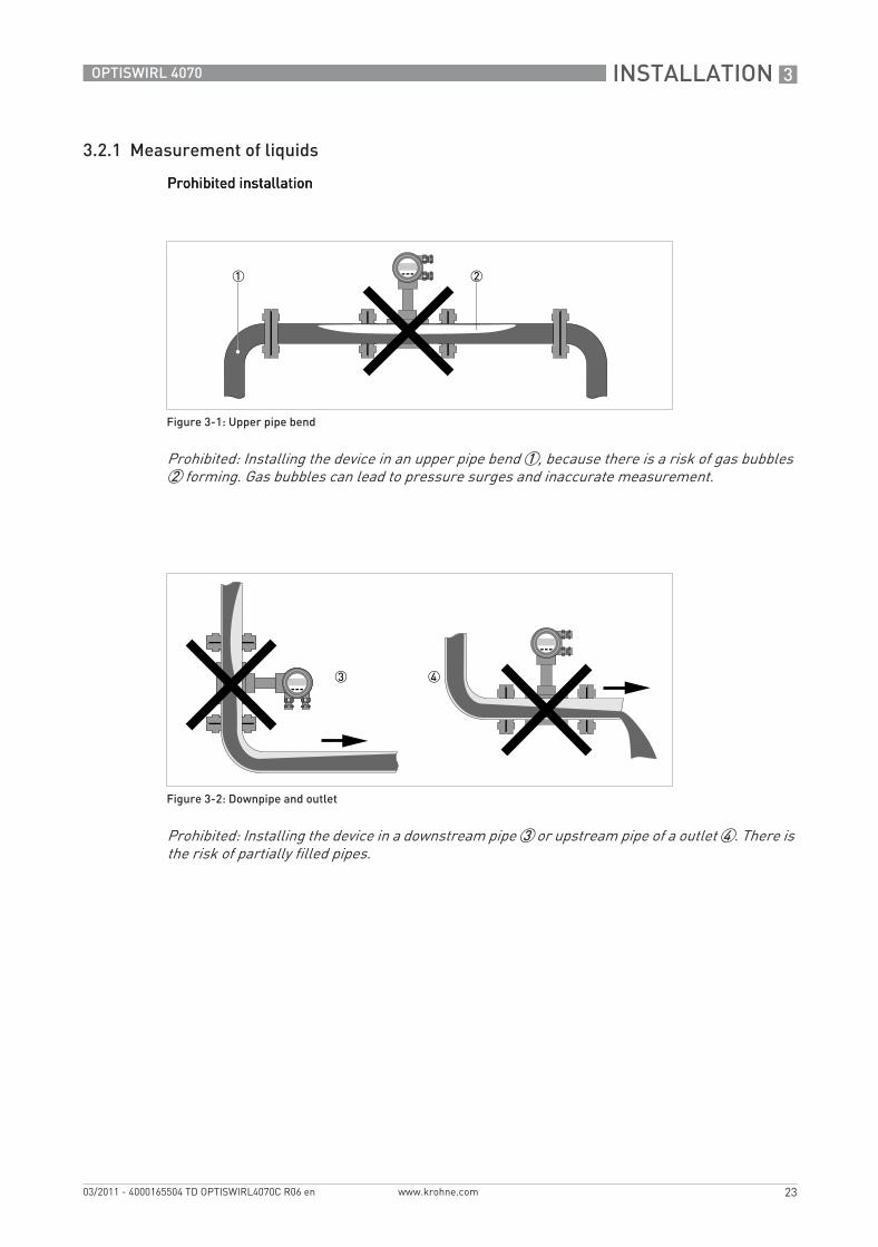
Prohibited installationProhibited installationProhibited installationProhibited installation
Figure 3-1: Upper pipe bend
Prohibited: Installing the device in an upper pipe bend 1, because there is a risk of gas bubbles 2 forming. Gas bubbles can lead to pressure surges and inaccurate measurement.
Figure 3-2: Downpipe and outlet
Prohibited: Installing the device in a downstream pipe 3 or upstream pipe of a outlet 4. There is the risk of partially filled pipes.
TD_OPTISWIRL4070C_R06_en_165504_PRT.book Page 23 Thursday, March 24, 2011 7:05 AM
3 INSTALLATION
24
OPTISWIRL 4070
www.krohne.com 03/2011 - 4000165504 TD OPTISWIRL4070C R06 en
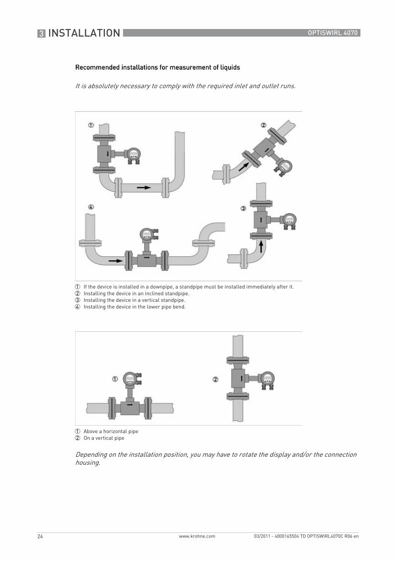
Recommended installations for measurement of liquidsRecommended installations for measurement of liquidsRecommended installations for measurement of liquidsRecommended installations for measurement of liquids
It is absolutely necessary to comply with the required inlet and outlet runs.
1 If the device is installed in a downpipe, a standpipe must be installed immediately after it.2 Installing the device in an inclined standpipe.3 Installing the device in a vertical standpipe.4 Installing the device in the lower pipe bend.
1 Above a horizontal pipe2 On a vertical pipe
Depending on the installation position, you may have to rotate the display and/or the connection housing.
TD_OPTISWIRL4070C_R06_en_165504_PRT.book Page 24 Thursday, March 24, 2011 7:05 AM
INSTALLATION 3
25
OPTISWIRL 4070
www.krohne.com03/2011 - 4000165504 TD OPTISWIRL4070C R06 en
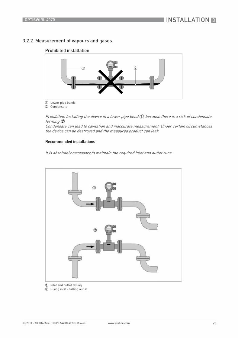
3.2.2 Measurement of vapours and gases
Recommended installationsRecommended installationsRecommended installationsRecommended installations
Prohibited installation
1 Lower pipe bends2 Condensate
Prohibited: Installing the device in a lower pipe bend 1, because there is a risk of condensate forming 2. Condensate can lead to cavitation and inaccurate measurement. Under certain circumstances the device can be destroyed and the measured product can leak.
It is absolutely necessary to maintain the required inlet and outlet runs.
1 Inlet and outlet falling2 Rising inlet - falling outlet
TD_OPTISWIRL4070C_R06_en_165504_PRT.book Page 25 Thursday, March 24, 2011 7:05 AM
3 INSTALLATION
26
OPTISWIRL 4070
www.krohne.com 03/2011 - 4000165504 TD OPTISWIRL4070C R06 en
3.2.3 Heat insulation
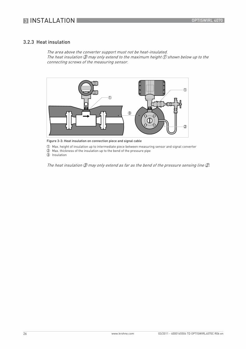
The area above the converter support must not be heat-insulated. The heat insulation 3 may only extend to the maximum height 1 shown below up to the connecting screws of the measuring sensor.
Figure 3-3: Heat insulation on connection piece and signal cable
1 Max. height of insulation up to intermediate piece between measuring sensor and signal converter2 Max. thickness of the insulation up to the bend of the pressure pipe3 Insulation
The heat insulation 3 may only extend as far as the bend of the pressure sensing line 2.
TD_OPTISWIRL4070C_R06_en_165504_PRT.book Page 26 Thursday, March 24, 2011 7:05 AM
INSTALLATION 3
27
OPTISWIRL 4070
www.krohne.com03/2011 - 4000165504 TD OPTISWIRL4070C R06 en
3.3 Inlet and outlet runs
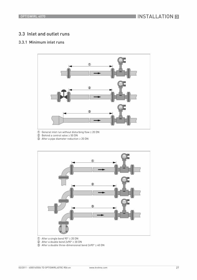
3.3.1 Minimum inlet runs
1 General inlet run without disturbing flow ≥ 20 DN2 Behind a control valve ≥ 50 DN3 After a pipe diameter reduction ≥ 20 DN
1 After a single bend 90° ≥ 20 DN2 After a double bend 2x90° ≥ 30 DN3 After a double three-dimensional bend 2x90° ≥ 40 DN
TD_OPTISWIRL4070C_R06_en_165504_PRT.book Page 27 Thursday, March 24, 2011 7:05 AM
3 INSTALLATION
28
OPTISWIRL 4070
www.krohne.com 03/2011 - 4000165504 TD OPTISWIRL4070C R06 en
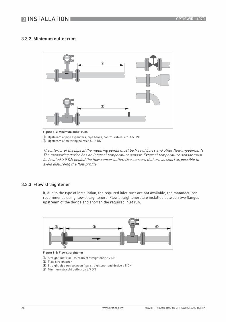
3.3.2 Minimum outlet runs
3.3.3 Flow straightener
If, due to the type of installation, the required inlet runs are not available, the manufacturer recommends using flow straighteners. Flow straighteners are installed between two flanges upstream of the device and shorten the required inlet run.
Figure 3-4: Minimum outlet runs
1 Upstream of pipe expanders, pipe bends, control valves, etc. ≥ 5 DN2 Upstream of metering points ≥ 5…6 DN
The interior of the pipe at the metering points must be free of burrs and other flow impediments. The measuring device has an internal temperature sensor. External temperature sensor must be located ≥ 5 DN behind the flow sensor outlet. Use sensors that are as short as possible to avoid disturbing the flow profile.
Figure 3-5: Flow straightener
1 Straight inlet run upstream of straightener ≥ 2 DN2 Flow straightener3 Straight pipe run between flow straightener and device ≥ 8 DN4 Minimum straight outlet run ≥ 5 DN
TD_OPTISWIRL4070C_R06_en_165504_PRT.book Page 28 Thursday, March 24, 2011 7:05 AM
ELECTRICAL CONNECTIONS 4
29
OPTISWIRL 4070
www.krohne.com03/2011 - 4000165504 TD OPTISWIRL4070C R06 en
Electrical connections
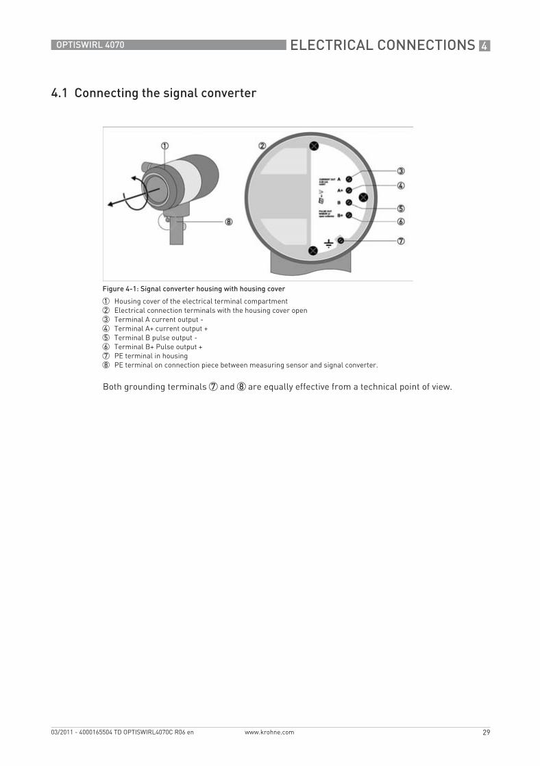
4.1 Connecting the signal converter
Both grounding terminals 7 and 8 are equally effective from a technical point of view.
Figure 4-1: Signal converter housing with housing cover
1 Housing cover of the electrical terminal compartment2 Electrical connection terminals with the housing cover open3 Terminal A current output -4 Terminal A+ current output +5 Terminal B pulse output -6 Terminal B+ Pulse output +7 PE terminal in housing8 PE terminal on connection piece between measuring sensor and signal converter.
TD_OPTISWIRL4070C_R06_en_165504_PRT.book Page 29 Thursday, March 24, 2011 7:05 AM
4 ELECTRICAL CONNECTIONS
30
OPTISWIRL 4070
www.krohne.com 03/2011 - 4000165504 TD OPTISWIRL4070C R06 en
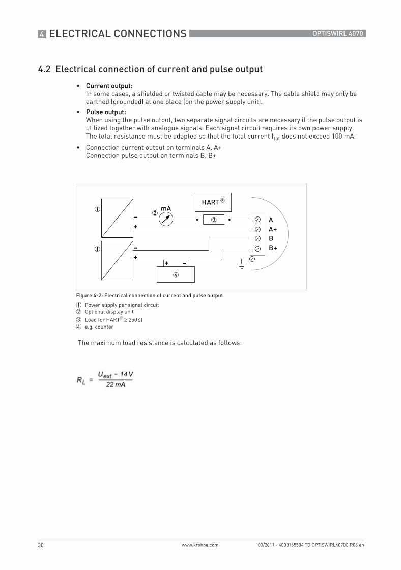
4.2 Electrical connection of current and pulse output
• Current output:Current output:Current output:Current output:In some cases, a shielded or twisted cable may be necessary. The cable shield may only be earthed (grounded) at one place (on the power supply unit).
• Pulse output:Pulse output:Pulse output:Pulse output:When using the pulse output, two separate signal circuits are necessary if the pulse output is utilized together with analogue signals. Each signal circuit requires its own power supply. The total resistance must be adapted so that the total current Itot does not exceed 100 mA.
• Connection current output on terminals A, A+Connection pulse output on terminals B, B+
The maximum load resistance is calculated as follows:
Figure 4-2: Electrical connection of current and pulse output
1 Power supply per signal circuit2 Optional display unit
3 Load for HART® ≥ 250 Ω4 e.g. counter
TD_OPTISWIRL4070C_R06_en_165504_PRT.book Page 30 Thursday, March 24, 2011 7:05 AM
ELECTRICAL CONNECTIONS 4
31
OPTISWIRL 4070
www.krohne.com03/2011 - 4000165504 TD OPTISWIRL4070C R06 en
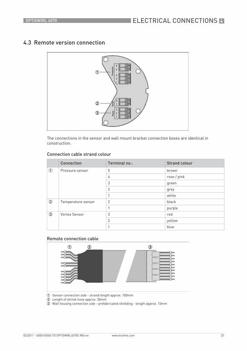
4.3 Remote version connection
The connections in the sensor and wall mount bracket connection boxes are identical in construction.
Connection cable strand colour
Connection Terminal no.: Strand colour
1 Pressure sensor 5 brown
4 rose / pink
3 green
2 grey
1 white
2 Temperature sensor 2 black
1 purple
3 Vortex Sensor 3 red
2 yellow
1 blue
Remote connection cable
1 Sensor connection side - strand length approx. 100mm2 Length of shrink hose approx. 30mm3 Wall housing connection side - prefabricated shielding - length approx. 15mm
TD_OPTISWIRL4070C_R06_en_165504_PRT.book Page 31 Thursday, March 24, 2011 7:05 AM
5 ORDER FORM
32
OPTISWIRL 4070
www.krohne.com 03/2011 - 4000165504 TD OPTISWIRL4070C R06 en
Order form
Please provide us with the missing information so that we can be of help to you as quickly as possible.
Then please fax this page to the appropriate sales associate. We will then contact you as soon as possible.
Device data
Rating data
Contact data
Nominal connection size:
Pressure rating:
Raised face:
Material of pipeline:
Connection type: Flange Sandwich
Design: Compact Remote 5 m cable length Remote 10 m cable length
Display: With Without
Approval: No Ex ATEX II 2G Ex d ia [ia] IIC T6 FM Class 1 Div. 1
Product:
Operating pressure:
Rated pressure:
Operating temperature:
Rated temperature:
Operating density:
Viscosity:
Measuring range:
Comments:
Company:
Contact person:
Telephone number:
Fax number:
E-mail:
TD_OPTISWIRL4070C_R06_en_165504_PRT.book Page 32 Thursday, March 24, 2011 7:05 AM

NOTES 6
33
OPTISWIRL 4070
www.krohne.com03/2011 - 4000165504 TD OPTISWIRL4070C R06 en
Notes
TD_OPTISWIRL4070C_R06_en_165504_PRT.book Page 33 Thursday, March 24, 2011 7:05 AM

6 NOTES
34
OPTISWIRL 4070
www.krohne.com 03/2011 - 4000165504 TD OPTISWIRL4070C R06 en
TD_OPTISWIRL4070C_R06_en_165504_PRT.book Page 34 Thursday, March 24, 2011 7:05 AM

NOTES 6
35
OPTISWIRL 4070
www.krohne.com03/2011 - 4000165504 TD OPTISWIRL4070C R06 en
TD_OPTISWIRL4070C_R06_en_165504_PRT.book Page 35 Thursday, March 24, 2011 7:05 AM

KROHNE product overview
• Electromagnetic flowmeters
• Variable area flowmeters
• Ultrasonic flowmeters
• Mass flowmeters
• Vortex flowmeters
• Flow controllers
• Level meters
• Temperature meters
• Pressure meters
• Analysis products
• Measuring systems for the oil and gas industry
• Measuring systems for sea-going tankers
Head Office KROHNE Messtechnik GmbHLudwig-Krohne-Str. 5D-47058 Duisburg (Germany)Tel.:+49 (0)203 301 0Fax:+49 (0)203 301 10389 [email protected]
© K
RO
HN
E 03
/201
1 -
4000
1655
04 T
D O
PTI
SWIR
L407
0C R
06 e
n -
Subj
ect t
o ch
ange
with
out n
otic
e.
The current list of all KROHNE contacts and addresses can be found at:www.krohne.com
KK
K
TD_OPTISWIRL4070C_R06_en_165504_PRT.book Page 36 Thursday, March 24, 2011 7:05 AM


![NATURAL SCIENCES D568/12 ADMISSIONS ASSESSMENT 40 … · Ω, 2 Ω, 4 Ω, 8 Ω, 16 Ω, 32 Ω, 64 Ω, … connected in parallel with the cell. ... [2 marks] Answer: ... is used as the](https://img.pdfslide.net/doc/110x75/5f2363f7b03d7e4ce06bc15b/natural-sciences-d56812-admissions-assessment-40-2-4-8-16-32.jpg)