Embed Size (px)
Citation preview
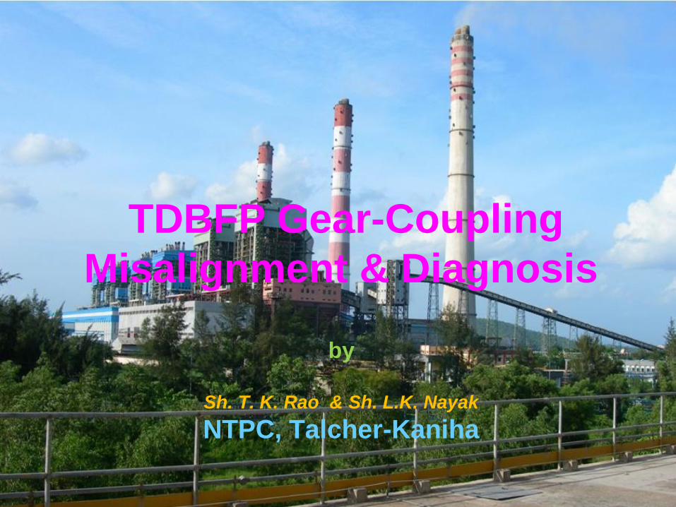
TDBFP Gear-Coupling
Misalignment & Diagnosis
by
Sh. T. K. Rao & Sh. L.K. Nayak
NTPC, Talcher-Kaniha
TDBFP - Criticality
TDBFPs are major Turbine Auxiliary vital to Power generation and at
the same time they help in improving overall cycle efficiency.
Unavailability of TDBFPs leads to running of MDBFP thereby
increases Auxiliary Power Consumption.
Availability & reliability of TDBFPs play a major role in Power plant
performance, and assumes much higher significance under PAT
regime.
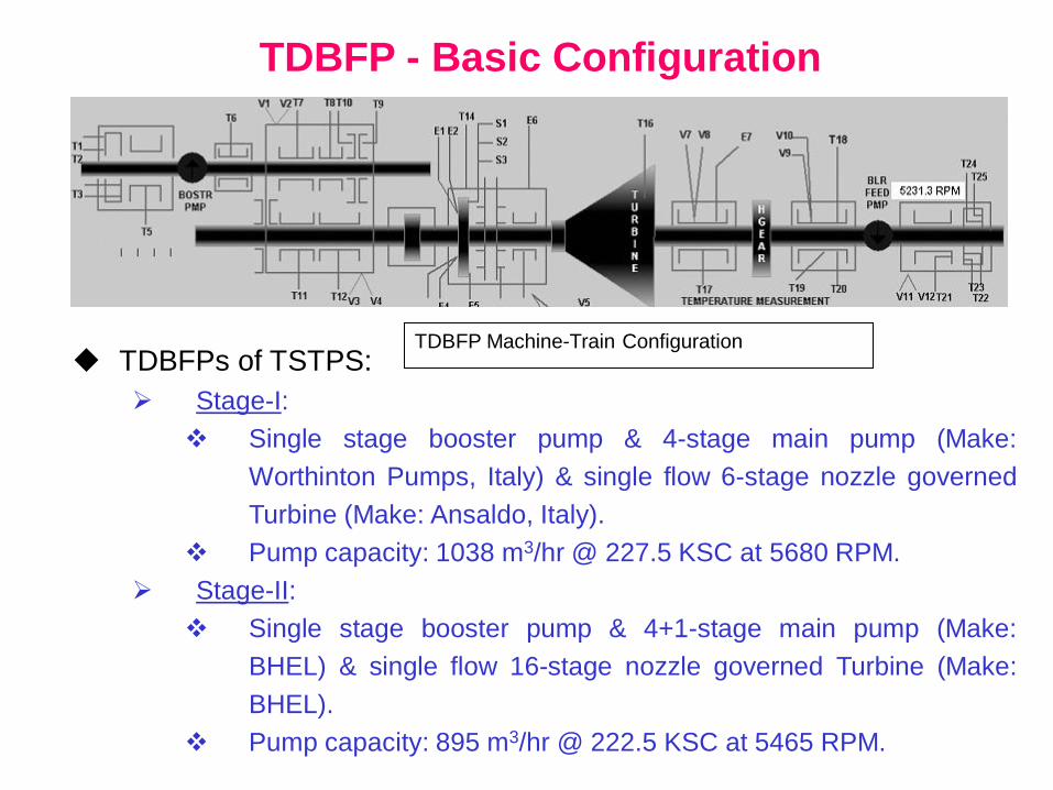
TDBFP - Basic Configuration
TDBFPs of TSTPS:
Stage-I:
Single stage booster pump & 4-stage main pump (Make:
Worthinton Pumps, Italy) & single flow 6-stage nozzle governed
Turbine (Make: Ansaldo, Italy).
Pump capacity: 1038 m3/hr @ 227.5 KSC at 5680 RPM.
Stage-II:
Single stage booster pump & 4+1-stage main pump (Make:
BHEL) & single flow 16-stage nozzle governed Turbine (Make:
BHEL).
Pump capacity: 895 m3/hr @ 222.5 KSC at 5465 RPM.
TDBFP Machine-Train Configuration
TDBFP - Alignment Facts
Complexities of TDBFP Alignment
Precision alignment of coupled shafts within acceptable tolerances is
necessary to avoid undue stress & premature failure of components.
Alignment of multi-shaft machine is a cumbersome task, and gets
further complicated where different sub-equipments have significantly
different thermal growth from cold-to-hot running conditions like TDBFP.
Manufacturers recommend cold-offsets to be provided during alignment
to take care of thermal growth issues.
Gear-couplings have also been provided to accommodate thermal
expansion & some amount of misalignment to minimise undue stress
on shafts, bearings, seals, etc.
Early detection of misalignment can help in reducing component
failures due to undue stress thereby increase equipment availability &
reliability.
Misalignment Detection
Misalignment Characteristics
Misalignment disguises itself well on machinery and what we observe
are secondary effects of misalignment as it slowly damages machine
components.
Common effects of misalignment are stressed components, elevated
temperature, premature bearing, seal, coupling or shaft failures,
excessive leakage at seals, etc.
Tools & techniques commonly used for detecting any coupling &
alignment problems during running of the equipment is monitoring of
parameters like vibration, temperature, etc.
Misalignment Detection...
Misalignment Detection through Vibration
Amount of misalignment cannot be directly reflected by vibration
because of the followings:
Misalignment exerts static forces on machinery components,
whereas Vibration is the system response to dynamic forces on
machinery.
Vibration sensors measure Motion, and not Force.
Modified dynamic behaviour of machine components under stress
due to misalignment is measured through vibration.
Amount of vibratory motion is dependent on mass, stiffness &
damping, and change in any of these characteristics can change
vibration amplitude without any change in force.
The vibration amplitude cannot solely & accurately reflect the
misalignment condition & its severity. In fact, the vibration amplitude
increases at times after correcting misalignment condition.
Misalignment Detection...
Additional Online Tools for Detecting Misalignment
When machine components are stressed due to misalignment, they will
definitely generate heat during motion, and that can be detected
through thermal measurement.
Temperature change due to misalignment is also found to be varying
almost linearly with change in alignment.
Temperature monitoring or thermography of coupling & inboard
components can be used to detect misalignment.
Vibration Characteristics of Gear-Coupling Misalignment & Wear
Misalignment can usually be detected by following vibration symptoms:
High 1X or 2X vibration components
Comparatively higher axial vibration levels
Out of phase vibrations across the coupling
Misalignment Detection...
Vibration Characteristics of Gear-Coupling Misalignment & Wear...
These symptoms can appear during misalignment, but not always.
Vibration spectral pattern due to misalignment will frequently be
different depending on type of coupling, shaft & support bearing.
Vibration signatures from misalignment of equipments with flexible
couplings have components at other multiples of running speed like 3X,
4X, 6X etc, but the phase angle information makes sense only if the
predominant vibration component is 1X.
Gear-couplings, being flexible, do absorb some amount of
misalignment by stressing themselves. So, the actual misalignment
severity is not reflected in the shaft or bearing vibrations.
Under this suppressed misalignment condition, the couplings may wear
out faster due to increased stress & friction. A worn-out gear-coupling
may then slip above certain load/speed leading to rub & rotor instability
which is reflected in vibration misleading the diagnosis of real cause.
TDBFP- Case Study
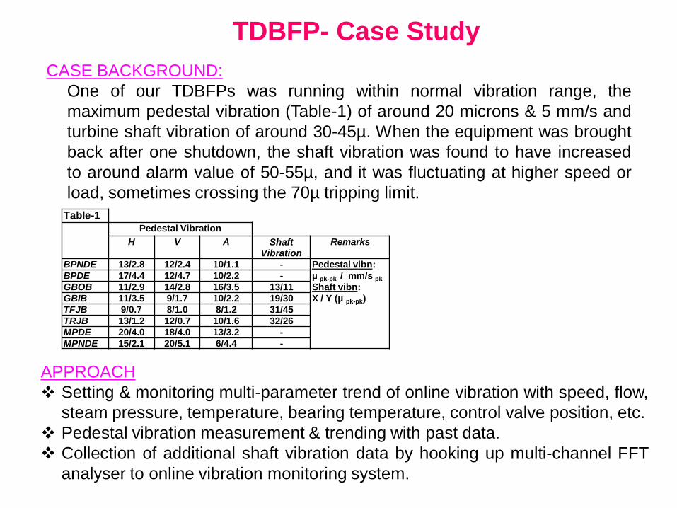
CASE BACKGROUND:
One of our TDBFPs was running within normal vibration range, the
maximum pedestal vibration (Table-1) of around 20 microns & 5 mm/s and
turbine shaft vibration of around 30-45µ. When the equipment was brought
back after one shutdown, the shaft vibration was found to have increased
to around alarm value of 50-55µ, and it was fluctuating at higher speed or
load, sometimes crossing the 70µ tripping limit.
Table-1 Pedestal Vibration
H V A Shaft Vibration
Remarks
BPNDE 13/2.8 12/2.4 10/1.1 - Pedestal vibn:
µ pk-pk / mm/s pk
Shaft vibn:
X / Y (µ pk-pk)
BPDE 17/4.4 12/4.7 10/2.2 -
GBOB 11/2.9 14/2.8 16/3.5 13/11
GBIB 11/3.5 9/1.7 10/2.2 19/30
TFJB 9/0.7 8/1.0 8/1.2 31/45
TRJB 13/1.2 12/0.7 10/1.6 32/26
MPDE 20/4.0 18/4.0 13/3.2 -
MPNDE 15/2.1 20/5.1 6/4.4 -
APPROACH
Setting & monitoring multi-parameter trend of online vibration with speed, flow,
steam pressure, temperature, bearing temperature, control valve position, etc.
Pedestal vibration measurement & trending with past data.
Collection of additional shaft vibration data by hooking up multi-channel FFT
analyser to online vibration monitoring system.
TDBFP- Case Study…
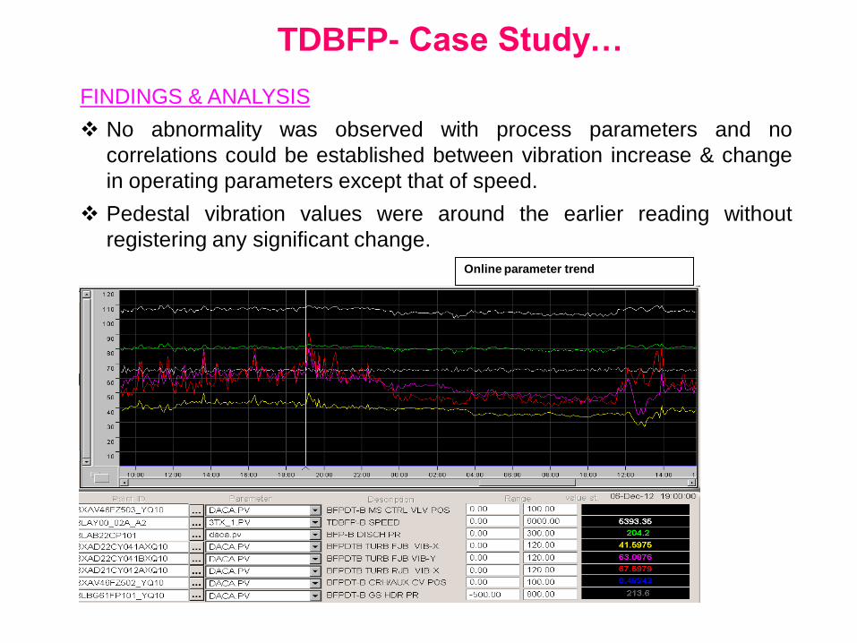
FINDINGS & ANALYSIS
No abnormality was observed with process parameters and no
correlations could be established between vibration increase & change
in operating parameters except that of speed.
Pedestal vibration values were around the earlier reading without
registering any significant change.
Online parameter trend
TDBFP- Case Study…
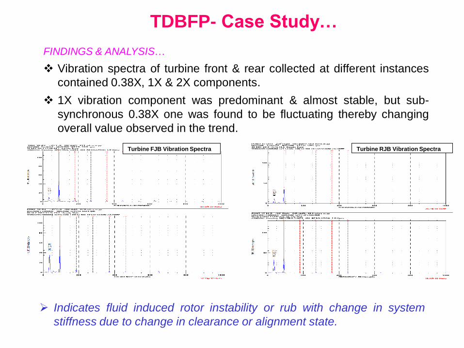
FINDINGS & ANALYSIS…
Vibration spectra of turbine front & rear collected at different instances
contained 0.38X, 1X & 2X components.
1X vibration component was predominant & almost stable, but sub-
synchronous 0.38X one was found to be fluctuating thereby changing
overall value observed in the trend.
Turbine FJB Vibration Spectra Turbine RJB Vibration Spectra
Indicates fluid induced rotor instability or rub with change in system
stiffness due to change in clearance or alignment state.
TDBFP- Case Study…
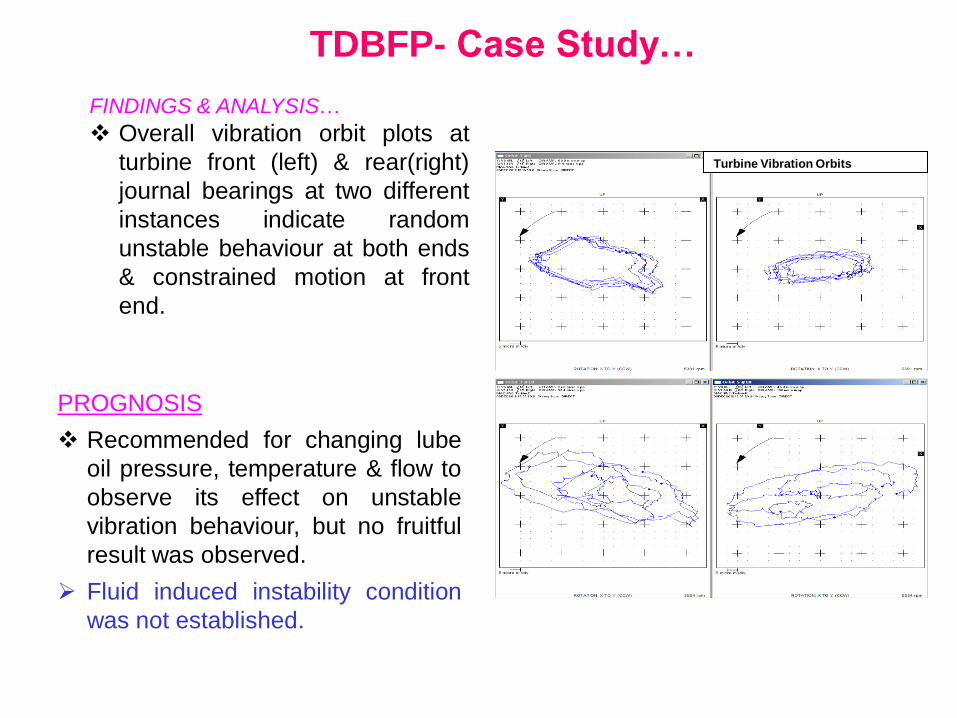
FINDINGS & ANALYSIS…
Overall vibration orbit plots at
turbine front (left) & rear(right)
journal bearings at two different
instances indicate random
unstable behaviour at both ends
& constrained motion at front
end.
Turbine Vibration Orbits
PROGNOSIS
Recommended for changing lube
oil pressure, temperature & flow to
observe its effect on unstable
vibration behaviour, but no fruitful
result was observed.
Fluid induced instability condition
was not established.
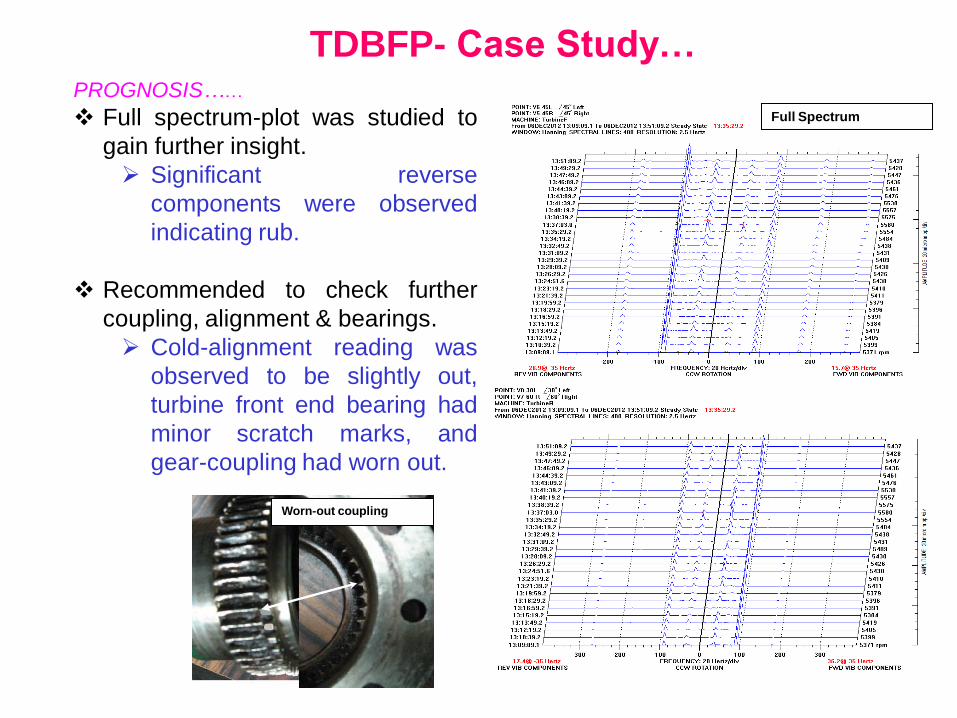
TDBFP- Case Study… PROGNOSIS……
Full spectrum-plot was studied to
gain further insight.
Significant reverse
components were observed
indicating rub.
Recommended to check further
coupling, alignment & bearings.
Cold-alignment reading was
observed to be slightly out,
turbine front end bearing had
minor scratch marks, and
gear-coupling had worn out.
Full Spectrum
Worn-out coupling
TDBFP- Case Study…
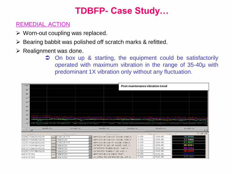
REMEDIAL ACTION
Worn-out coupling was replaced.
Bearing babbit was polished off scratch marks & refitted.
Realignment was done.
On box up & starting, the equipment could be satisfactorily
operated with maximum vibration in the range of 35-40µ with
predominant 1X vibration only without any fluctuation.
Post-maintenance vibration trend
TDBFP- Case Study…
POST-ANALYSIS & LEARNINGS
Comparing analysed & diagnosed problem with actual findings, following
significant learnings have emerged:
Presence of sub-synchronous component was attributed to fluid induced
rotor instability, but on seeing the worn-out coupling, actual source of it
could be explained
Because of worn-out teeth, gear-coupling might be slipping at
higher load & speed thereby generating rub & instability
symptoms.
Since, the direction of precision was not clearly evident from
key-phasor dots in chaotic orbit, rub condition was not clearly
visualised.
To further substantiate the findings, when full-spectrum plot
was studied, significant reverse components were observed at
turbine front end with worn-out coupling confirming the nature
of precision as that of rub.
Therefore, full-spectrum study should be employed along with
study of orbits & half spectrum to increase the probability of
correct diagnosis.
TDBFP- Case Study…
POST-ANALYSIS & LEARNINGS…
Increased 1X component was thought of occurring due to increased
clearance & minor misalignment. Although as-found cold-alignment
readings corroborated this, the cause of gear-coupling wear is perplexing.
Gear-coupling can absorb some amount of misalignment by
stressing itself, and to avoid wear due to friction under stressed
condition, it is lubricated.
It is quite possible that the lubricant might have been
leaked/squeezed out due to misalignment, thereby creating
friction & wear.
Such situation can arise due to unforeseen cold-to-hot
movement of the machine leading to misalignment in actual
running condition.
Hence, it is prudent to measure & compensate for actual
thermal growth by using some means like laser-detector
system.
TDBFP- Case Study…
POST-ANALYSIS & LEARNINGS…
It is not always possible to detect the severity of misalignment through
vibration because
Some misalignment can be absorbed by flexible couplings like
gear-coupling, and vibration reflects motion under dynamic
force and not static force due to misalignment.
We should employ other technologies like IR Thermography to
complement vibration for misalignment detection.
There is no easy or inexpensive ways to determine in certainty if the
rotating machinery is misaligned when it is running because
Misalignment disguises itself well in rotating machinery with
flexible couplings.
Therefore, it is better to actually check & verify alignment
values and gear-coupling lubrication at certain intervals or
suitable opportunity.
Conclusion TDBFP reliability & availability can be improved by:
1. Use of Full-spectrum along with orbit & other vibration plots to correctly
diagnose rub & fluid induced instability problems and addressing them.
2. Use of IR Thermography to complement vibration in detecting misalignment
conditions.
3. Employing tools like laser-detector system in determining for compensating
actual cold-to-hot movements to ensure running condition alignment within
acceptable tolerances.
4. Actual offline checking & rectification of alignment & lubrication condition of
gear-couplings at suitable opportunity to ensure their healthiness and avoid
premature component failures due to misalignment.
5. Additional investigation should be done to find & attend root cause of
significant shift in alignment, if any.


![U.S.A (SMA) SEISA GC Coupling · 2019-08-26 · T o r q u e T o r q u e [There is no parallel misalignment or angular misalignment] Internal gear [There is parallel misalignment [Engagement](https://img.pdfslide.net/doc/110x75/5e2d9b3c5cac73680f7fef18/usa-sma-seisa-gc-coupling-2019-08-26-t-o-r-q-u-e-t-o-r-q-u-e-there-is-no.jpg)