Embed Size (px)
Citation preview
IEEE INTERNET OF THINGS JOURNAL, VOL. 6, NO. 1, FEBRUARY 2019 867
TDMA in Adaptive Resonant BeamCharging for IoT Devices
Mingliang Xiong, Mingqing Liu, Qingqing Zhang, Student Member, IEEE,
Qingwen Liu , Senior Member, IEEE, Jun Wu , Senior Member, IEEE, and Pengfei Xia
Abstract—Resonant beam charging (RBC) can realize wirelesspower transfer (WPT) from a transmitter to multiple Internet ofThings devices via resonant beams. The adaptive RBC (ARBC)can effectively improve its energy utilization. In order to sup-port multiuser WPT in the ARBC system, we propose thetime-division multiple access (TDMA) method and design theTDMA-based WPT scheduling algorithm. Our TDMA WPTmethod has the features of concurrently charging, continuouscharging current, individual user power control, constant driv-ing power, and flexible driving power control. The simulationshows that the TDMA scheduling algorithm has high efficiency,as the total charging time is roughly half (46.9% when charg-ing 50 receivers) of that of the alternative scheduling algorithm.Furthermore, the TDMA for WPT inspires the ideas of enhanc-ing the ARBC system, such as flow control and quality ofservice.
Index Terms—Internet of Things (IoT), resonant beam charg-ing (RBC), time-division multiple access (TDMA), wireless powertransfer (WPT).
I. INTRODUCTION
W IRELESS power transfer (WPT) becomes an importantand urgent need for mobile devices, such as smart-
phones [1] and Internet of Things (IoT) devices [2], [3].Recently, Qihui Wu and Guoru Ding have made the pri-mary contributions to cognitive Internet of things (CIoT) andits applications, which provided valuable references for thiswork [4], [5]. For the emerging area of CIoT, a high-powerand human-safe WPT can promote the massive data acquisi-tion and analysis of CIoT devices. WPT, as known as wirelesscharging, can be classified into nonradiative coupling-basedcharging and radiative radio frequency-based charging [6]. Interms of power transmission distance, wireless charging canbe classified into far-field charging and near-field charging [7].The WPT technologies, such as inductive coupling [8], mag-netic resonance coupling [9], [10], capacitive coupling [11],radio waves [12], and laser [13], have been well investigatedin researches. However, these WPT technologies are facingvarious technical challenges. For instance, inductive couplinghas to operate in short-distance; radio-wave charging suffers
Manuscript received May 8, 2018; accepted July 31, 2018. Date ofpublication August 6, 2018; date of current version February 25, 2019.(Corresponding author: Qingwen Liu.)
The authors are with the Department of Computer Science andTechnology, Tongji University, Shanghai 201804, China, (e-mail:[email protected]; [email protected]; [email protected];[email protected]; [email protected]; [email protected]).
Digital Object Identifier 10.1109/JIOT.2018.2863232
Fig. 1. RBC features.
low efficiency; and laser charging has the difficulty to meetthe safety requirements.
Resonant beam charging (RBC), as known as distributedlaser charging [14], can transfer energy via a resonant beambetween the transmitter and the receiver. Fig. 1 shows theRBC features including high-power, intrinsic-safe, mobile, andbroadcasting. RBC can safely charge multiple moving deviceswith Watt-level power over meter-level distances like WiFicommunications. The adaptive RBC (ARBC) system pro-posed in [15] improved the WPT efficiency based on feedbackcontrol like link adaptation in wireless communications.
Although single-user ARBC was presented in [15], mul-tiuser WPT in the ARBC system is important and worthof investigating for the applications like wireless sensor net-works [16]–[18]. Thus, multiple access in the ARBC systemneeds to be studied. Furthermore, it is also interesting tofind out an efficient scheduling method for multiuser WPTin the ARBC system, in order to satisfy each user’s energyrequirement.
In this paper, we propose two types of power control meth-ods for the multiuser ARBC system: 1) the alternative chargingand 2) the time-division multiple access (TDMA) charging.
Alternative Charging: The transmitter transfers properpower to one receiver for a period of time and then switchesto another. However, this design has two obvious limitations:1) the efficiency is low as only one receiver can be chargedin each charging period and 2) charging current may bediscontinuous due to user switch.
TDMA Charging: It combines time-division multiplexing(TDM) and pulse width modulation (PWM) for multiuser
2327-4662 c© 2018 IEEE. Personal use is permitted, but republication/redistribution requires IEEE permission.See http://www.ieee.org/publications_standards/publications/rights/index.html for more information.
868 IEEE INTERNET OF THINGS JOURNAL, VOL. 6, NO. 1, FEBRUARY 2019
WPT, which has neither of the above limitations. In commu-nication systems, TDM was originally introduced to combinemultiple signals in one channel in time domain [19]. Then,TDM was adopted for WPT as TDM-WPT in [20]. PWMtechnology provides an approach to convert pulses into con-tinuous current, which is widely adopted in switching modepower supply (SMPS) [21]. We employ TDM to handle mul-tiuser WPT and employ PWM to realize continuous currentcharging.
The contribution of this paper includes: 1) we design andanalyze the PWM-assisted TDMA method for multiuser WPTin the ARBC system and 2) we propose the TDMA-basedscheduling algorithm to realize efficient and flexible mul-tiuser WPT in the ARBC system. The proposed TDMA-basedcharging design has the following features.
1) Concurrently Charging: Multiple receivers can becharged concurrently.
2) Individual User Power Control: The charging power ofeach receiver can be controlled independently.
3) Continuous Charging Current: The charging current ofeach receiver is continuous.
4) Constant Driving Power: The driving power at the trans-mitter can keep constant and avoid being frequentlyswitched as in alternative charging, which leads to low-complexity and robustness for the transmitter design.
5) Flexible Driving Power Control: The driving power canbe flexible regardless of charging power requirements.
Compared with the alternative charging method, the TDMA-based method has the following benefits.
1) Charging Efficiency: The total charging time for multipleusers is 46.9% of that of the alternative charging.
2) Output Capability: There is no limit on output power.3) User Capacity: The system can support more users due
to the improvement of output capability.In Section II, we introduce the principle of RBC; present
the point-to-point ARBC system; depict the multiuser charg-ing problem in the ARBC system; and demonstrate thealternative charging method. In Section III, we propose theTDMA method for multiuser WPT in the ARBC system. InSection IV, we depict the TDMA-based scheduling algorithm.In Section V, we illustrate the simulation to compare theefficiency between the alternative and TDMA-based charg-ing methods, and summarize the features of the TDMA-basedscheduling algorithm. Finally, in Section VI, we make theconclusions and discuss the future research topics.
II. SYSTEM DESCRIPTION
In this section, we first introduce the principle of RBC.Then, we depict the point-to-point ARBC system which sup-ports the TDMA charging in Section III. Next, we demonstratethe necessity of multiuser power control when charging mul-tiple receivers. At last, we propose the alternative schedulingalgorithm and discuss its features.
A. Resonant Beam Charging
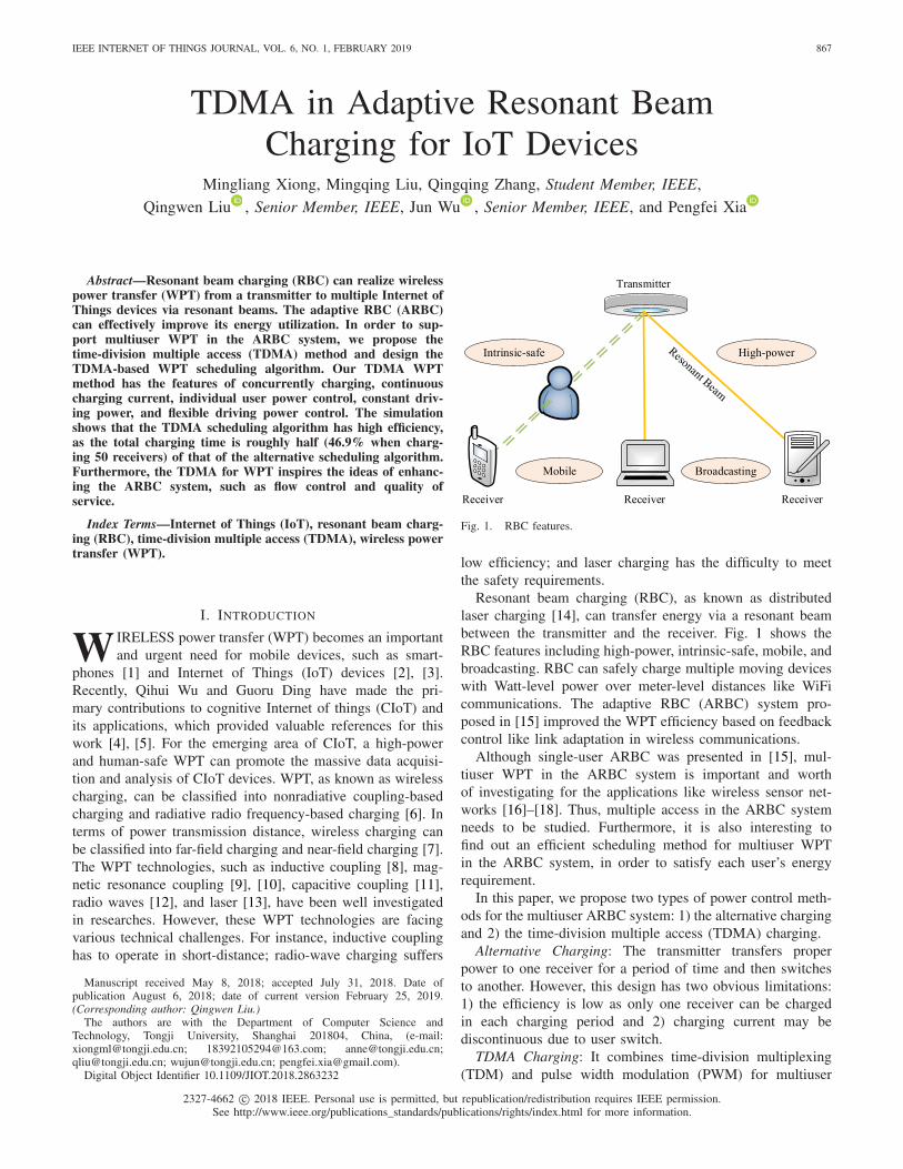
As shown in Fig. 2, the RBC system consists of twoparts: 1) the transmitter and 2) the receiver. In the system,
Fig. 2. ARBC system.
the transmitter and the receiver constitute the resonant cavity.Therefore, differing from the traditional laser cavity, the RBCcavity is separated in space. R1 and R2 are retro-reflectors,which can reflect the beam to the reverse direction regardlessof the incident angle [22]. Between the two retro-reflectors, thephotons are reflected repeatedly to stimulate out more photonswhile passing through the gain medium. Hence, the resonantbeam connecting R1 and R2 can be formed naturally withoutconcerning about the location of the receiver. The above mech-anism guarantees the features of mobility and broadcasting. Asa retro-reflector with 95% reflective, R2 allows a part of thephotons passing through. Therefore, a laser beam can outputfrom the back of R2, which can provide high-power energy.Furthermore, any obstacles such as human bodies and clothesthat enter the resonating beam path will disrupt the resonanceimmediately, which provides the intrinsic safety. At last, thebeam can be converted into current by the photovoltaic (PV)cell to charge the battery.
B. Point-to-Point System
The point-to-point system is depicted in Fig. 2. In the trans-mitter, the driver provides the driving power for the gainmedium to generate the beam. This process converts electricalenergy into optical energy. Then, the beam travels through theair, resonating between the transmitter and the receiver. Thepath controller is composed of an optical switches array, andit is adopted to switch the on–off state of the beam path. Inthe receiver, the PV cell converts optical energy into electricalenergy. As the most important element for the implementationof the TDMA charging method, the power buffer can convertPWM power into continuous smooth power. However, for thealternative charging, the power buffer should be bypassed byclosing the switch. The direct current to direct current (dc–dc)converter ensures that the charging voltage and the chargingcurrent can satisfy the battery’s requirement. The communica-tion modules can transmit battery states from the receiver tothe transmitter via the signaling channel. At the transmitter,the power controller can control the driving power.
In the system model, the electrical energy provided by thedriver is converted into optical energy with the efficiency ηs.The transmission efficiency of the path controller is ηpc. Due topropagation attenuation, the resonant beam power experiencespower loss with the transmission efficiency ηt. Moreover, thephotoelectric conversion efficiency of the PV cell is ηr. The

XIONG et al.: TDMA IN ARBC FOR IoT DEVICES 869
Fig. 3. Power buffer principle.
conversion efficiency of the power buffer is ηpb. The con-version efficiency of the dc–dc converter is ηdc. We definethe driving power as Pd, then the charging power Pc can beobtained as
Pc = ηsηpcηtηrηpbηdcPd. (1)
The principle of the power buffer is depicted in Fig. 3. ThePWM wave is input to the power buffer, and the output is thecontinuous current. The circuit of the power buffer is similarto that of an SMPS, which consists of the energy storage com-ponents such as inductors and capacitors [23]. Inductors havethe ability to store electrical energy by converting it into mag-netic energy. Similarly, capacitors store electrical energy in theform of electric charges. As pulses enter the power buffer, theanalysis can be divided into two stages.
1) ON Stage: The input power of the power buffer is at ahigh level, which is notated as the peak input power Pbip;and the diode remains a cut-off state while the capacitoris being charged by the inductor. As a result, the outputvoltage rises up slowly.
2) OFF Stage: Following the ON stage, the input powerturns to zero, and the diode is switched on. Thus, theenergy stored in the inductor is released to the capacitorand the load. Therefore, the output voltage goes downslowly.
In theory, there is no energy consumption in such compo-nents as inductors and capacitors without resistance. Becauseof the law of energy conservation in a period
Ebo = Ebi (2)
it can be induced that
PboTw = Pbip · TON + 0 × (Tw − TON) (3)
where Ebi is the input energy, Ebo is the output energy, Pbip isthe peak power of the input pulse, Pbo is the constant outputpower, TON is the time width of the pulse (ON stage), and Tw
is the period of the PWM wave. The duty cycle δ of the PWMwave is depicted as
δ = TON
Tw. (4)
Hence, from (3) and (4), it can be derived that
Pbo = δPbip. (5)
Then, from (1) and (5), the charging power can be obtained as
Pc = ηδPd (6)
where
η = ηsηpcηtηrηpbηdc. (7)
Fig. 4. Li-ion battery charging profile.
Fig. 5. Multiuser power control.
From (6), we can verify that the charging power can bedetermined by the duty cycle of the PWM beam.
C. Multiuser Power Control
RBC has the broadcasting feature, as the resonant beamscan be formed between one transmitter and multiple receivers.However, the broadcast charging is less efficient in energyutilization, because the RBC system cannot track the receivers’power requirements concurrently.
Owing to the advantages of high energy density and longcycling life, Li-ion batteries are the most common energystorage components in mobile devices. The specified con-stant current–constant voltage (CC–CV) charging algorithmcan optimize the battery performance [24]. The CC–CV algo-rithm can be depicted in Fig. 4 which is called the Li-ionbattery charging profile. The charging profile has four stages ina charge circle, which are trickle charge, constant current (CC),constant voltage (CV), and charge terminal, respectively [24].
According to the CC–CV algorithm, the battery is chargedwith the dynamic power in the ARBC system. From Fig. 4,when charging the 1000 mAh Li-ion battery, the chargingpower rises up from zero to the maximum value (4.2 W) andthen goes back to zero smoothly. Hence, each receiver has aunique desired charging power Pc according to the chargingprofile during the charging period. As shown in Fig. 5, thecharging power delivered to each receiver should be specified.In order to optimize each receiver’s battery performance, thecharging power per receiver should be controlled according to
870 IEEE INTERNET OF THINGS JOURNAL, VOL. 6, NO. 1, FEBRUARY 2019
Fig. 6. Alternative charging principle.
its battery charging profile. Therefore, how to realize multiuserpower control in the ARBC system to track the receivers’requirements concurrently becomes an important issue.
D. Alternative Charging
In order to realize multiuser power control, the alternativecharging is an intuitive method without the power buffer (i.e.,the switch is closed in Fig. 2). In Fig. 6, time is divided into asequence of small frames with the same width. In each frame,the transmitter generates a beam for only one receiver (R1, R2,R3, R4, or R5) sequentially with the receiver’s battery desiredcharging power. This charging procedure (charging from R1 toR5 in turns) will repeat until all the receivers are fully charged.Thus, the scheduling algorithm can be depicted as follows.
Alternative Scheduling Algorithm: To charge the receiverssequentially with their desired battery charging power,repeatedly, and removes those receivers whose capacityreaches to 100%.
However, after being charged in one frame, the receiverhave to wait for its next charging frame in a long time (e.g.,four frames in Fig. 6). Therefore, the alternative charging hasthe disadvantages of low efficiency and discontinuous batterycharging current.
The driving power at the transmitter is switched over aframe. The frequent driving power adjustment may be harm-ful for the gain medium and lead to the complex transmitterdesign. Moreover, the driving power is constrained to satisfyonly one receiver’s requirement per frame, which is inflexibleand leads to the restricted output capability. To solve thoseproblems, a more efficient and flexible multiple access methodwill be proposed in the next section.
III. TDMA CHARGING DESIGN
In this section, we propose the TDMA charging design inthe ARBC system, which have the features of currently mul-tiuser charging, individual user power control and continuouscharging current. We at first demonstrate the TDMA chargingprinciple. Then, we propose the digitalized design to facilitatethe computer control.
A. TDMA Charging Principle
With the system illustrated in Section II, the transmit-ter should send the ON–OFF alternative PWM beam to thereceiver, and the charging power can be determined by theduty circle (pulse width) of the PWM beam. The pulse takesonly two stages: 1) the ON stage and 2) the OFF stage. During
Fig. 7. Time-division multiple accessing charging principle.
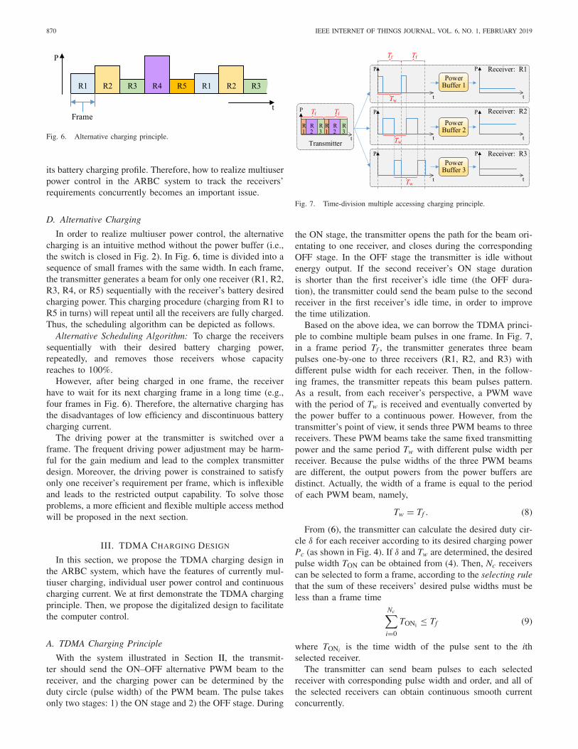
the ON stage, the transmitter opens the path for the beam ori-entating to one receiver, and closes during the correspondingOFF stage. In the OFF stage the transmitter is idle withoutenergy output. If the second receiver’s ON stage durationis shorter than the first receiver’s idle time (the OFF dura-tion), the transmitter could send the beam pulse to the secondreceiver in the first receiver’s idle time, in order to improvethe time utilization.
Based on the above idea, we can borrow the TDMA princi-ple to combine multiple beam pulses in one frame. In Fig. 7,in a frame period Tf , the transmitter generates three beampulses one-by-one to three receivers (R1, R2, and R3) withdifferent pulse width for each receiver. Then, in the follow-ing frames, the transmitter repeats this beam pulses pattern.As a result, from each receiver’s perspective, a PWM wavewith the period of Tw is received and eventually converted bythe power buffer to a continuous power. However, from thetransmitter’s point of view, it sends three PWM beams to threereceivers. These PWM beams take the same fixed transmittingpower and the same period Tw with different pulse width perreceiver. Because the pulse widths of the three PWM beamsare different, the output powers from the power buffers aredistinct. Actually, the width of a frame is equal to the periodof each PWM beam, namely,
Tw = Tf . (8)
From (6), the transmitter can calculate the desired duty cir-cle δ for each receiver according to its desired charging powerPc (as shown in Fig. 4). If δ and Tw are determined, the desiredpulse width TON can be obtained from (4). Then, Nc receiverscan be selected to form a frame, according to the selecting rulethat the sum of these receivers’ desired pulse widths must beless than a frame time
Nc∑
i=0
TONi ≤ Tf (9)
where TONi is the time width of the pulse sent to the ithselected receiver.
The transmitter can send beam pulses to each selectedreceiver with corresponding pulse width and order, and all ofthe selected receivers can obtain continuous smooth currentconcurrently.
XIONG et al.: TDMA IN ARBC FOR IoT DEVICES 871
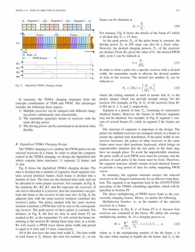
Fig. 8. Digitalized TDMA charging design.
In summary, the TDMA charging originates from theconcepts combination of TDM and PWM. The advantagesincludes the following three aspects.
1) Multiple receivers can be charged with different charg-ing power continuously and concurrently.
2) The transmitter generates beams to receivers with thesame driving power.
3) The driving power can be customized to an desired valueflexibly.
B. Digitalized TDMA Charging Design
The TDMA charging is to combine the PWM pulses for theselected receivers in a frame. In order to adopt the computercontrol in the TDMA charging, we design the digitalized rulewhich contains three structures: 1) segment; 2) frame; and3) slot.
Fig. 8 shows the digitalized TDMA charging design. Thetime is divided into a number of segments. Each segment con-tains several identical frames. Each frame is divided into anumber of slots. The slots are the identical time units and canbe allocated to some proper receivers. For example, in Fig. 8,the notations R1, R2, R3, and R4 represent the receivers. Ifone slot is allocated to a receiver, then the transmitter can gen-erate the beam to this receiver in this time slot. In Fig. 8, theadjacent slots with the same receiver notation constitute thisreceiver’s pulse. The pulses marked with the same receivernotation constitute a PWM that will be sent to the correspond-ing receiver. The peak power of these pulses is constant. Forinstance, in Fig. 8, the first six slots in each frame F2 aremarked as R1, so the transmitter Tx will switch the beam ori-entating to the receiver R1 during those time slots, as a result,R1 will receive a PWM wave whose pulse width and periodis equal to 6 slots and 15 slots, respectively.
All of the slots have the same time width Ts. The time widthof each frame is Tf . Hence, the total slot number, Ns, in one
frame can be obtained as
Ns = Tf
Ts. (10)
For instance, Fig. 8 shows the details of the frame F2 whichis divided into Ns = 15 slots.
As the peak power, Pp, of the pulse beam is constant, thedriving power Pd in ON stage can also be a fixed value.However, the desired charging powers, Pc, of the receiversare distinct. From (6), given the value of Pc, the desired PWMduty cycle δ can be induced as
δ = Pc
ηPd. (11)
In order to form a pulse for a specific receiver with a desiredwidth, the transmitter needs to allocate the desired numberof slots to the receiver. The desired slot number Nc can beinduced as
Nc = �δNs� =⌈
Pc
ηPdNs
⌉(12)
where the ceiling notation is used to ensure that Nc is theproper integer which can provide enough energy for thereceiver. For example, in Fig. 8, Nc of the receivers from R1to R4 are 6, 3, 4, and 2, respectively.
Segment is a period of time Tg, consisting of consecutiveidentical frames. However, the frames in different segmentsmay not be identical. For example, in Fig. 8, segment 1 con-sists of several frames F1, while in segment 2 the frames areF2.
The structure of segments is important in the design. Thepulses for multiple receivers are arranged closely in a frame toensure the optimal time distribution. If the pulse width of onereceiver increases, the pulses of other receivers in the sameframe must move their positions backward, which brings anunpredictable situation that the last pulse in the fame mayhave no enough place. To avoid the unpredictable situation,the pulse width of each PWM wave must be constant, and theposition of each pulse in the frame must be fixed. Therefore,the segment structure should contain several identical framesto provide a long period of time for stably outputting PWMwaves.
In summary, the segment structure ensures the selectedreceivers to be charged continuously for an effective long dura-tion. The segment is an important term in the OUTPUTTINGprocedure of the TDMA scheduling algorithm, which will bespecified in Section IV.
The above multiplexing of PWM waves leads to the con-currently charging feature. Hence, we define the following.
Multiplexing Number: ψ , as the number of the selectedreceivers in a frame.
For instance, in Fig. 8, ψ of frame F2 is 4, because fourreceivers are contained in the frame. We define the averagemultiplexing number, �, of a charging process as
� =∑
0≤ ti<Tu
ψiTf
Tu, i = 1, 2, 3, . . . , n (13)
where ψi is the multiplexing number of the ith frame, ti isthe time when starting to handle the ith frame, and Tu is the
872 IEEE INTERNET OF THINGS JOURNAL, VOL. 6, NO. 1, FEBRUARY 2019
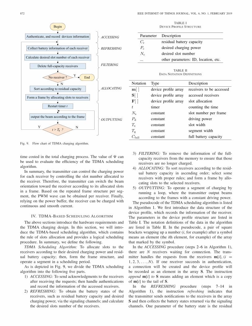
Fig. 9. Flow chart of TDMA charging algorithm.
time costed in the total charging process. The value of � canbe used to evaluate the efficiency of the TDMA schedulingalgorithm.
In summary, the transmitter can control the charging powerfor each receiver by controlling the slot number allocated tothe receiver. Therefore, the transmitter can switch the beamorientation toward the receiver according to its allocated slotsin a frame. Based on the repeated frame structure per seg-ment, the PWM wave can be obtained per receiver. Finally,relying on the power buffer, the receiver can be charged withcontinuous and smooth current.
IV. TDMA-BASED SCHEDULING ALGORITHM
The above sections introduce the hardware requirements andthe TDMA charging design. In this section, we will intro-duce the TDMA-based scheduling algorithm, which containsthe rule of slots allocation and provides a logical schedulingprocedure. In summary, we define the following.
TDMA Scheduling Algorithm: To allocate slots to thereceivers according to their desired charging power and resid-ual battery capacity; then, form the frame structure, andoperate a segment in a scheduling period.
As is depicted in Fig. 9, we divide the TDMA schedulingalgorithm into the following five parts.
1) ACCESSING: To send acknowledgments to the receiversafter receiving the requests; then handle authenticationsand record the information of the accessed receivers.
2) REFRESHING: To obtain the battery states of thereceivers, such as residual battery capacity and desiredcharging power, via the signaling channels; and calculatethe desired slots number of the receivers.
TABLE IDEVICE PROFILE STRUCTURE
TABLE IIDATA NOTATION DEFINITIONS
3) FILTERING: To remove the information of the full-capacity receivers from the memory to ensure that thosereceivers are no longer charged.
4) ALLOCATING: To sort receivers according to the resid-ual battery capacity in ascending order; select somereceivers with proper rules; and form a frame by allo-cating slots to the selected receivers.
5) OUTPUTTING: To operate a segment of charging byrunning a loop, where the transmitter output beamsaccording to the frames with a constant driving power.
The pseudocode of the TDMA scheduling algorithm is listedin Algorithm 1. We first introduce the data structure of thedevice profile, which records the information of the receiver.The parameters in the device profile structure are listed inTable I. The notation definitions of the data in the algorithmare listed in Table II. In the pseudocode, a pair of squarebrackets wrapping up a number (i, for example) after a symbolmeans an element (the ith element, for example) of the arraythat marked by the symbol.
In the ACCESSING procedure (steps 2–6 in Algorithm 1),there are N receivers waiting for connection. The trans-mitter handles the requests from the receivers m[i], (i =1, 2, 3, . . . ,N). If one receiver succeeds in authentication,a connection will be created and the device profile willbe recorded as an element in the array S. The instructionappend m[i] to S means adding an element which is a copyof m[i] to the tail of S.
In the REFRESHING procedure (steps 7–14 inAlgorithm 1), the instruction refreshing indicates thatthe transmitter sends notifications to the receivers in the arrayS and then collects the battery states returned via the signalingchannels. One parameter of the battery state is the residual

XIONG et al.: TDMA IN ARBC FOR IoT DEVICES 873
Algorithm 1 TDMA Scheduling1: begin2: for i = 1 to N do3: if m[i] is authenticated then4: append m[i] to S5: end if6: end for7: for i = 1 to length(S) do8: refresh S[i].Cr and S[i].Pc9: calculate S[i].Nc according to formula (12)
10: If S[i].Cr ≥ Cfull then delete S[i]11: end for12: if S is empty then13: end14: end if15: sort S according to S. Cr in ascending order16: for i = 1 to length(S) do17: if S[i].Nc ≤ Ns − length(F) then18: for j = 1 to S[i].Nc do19: append S[i] to F20: end for21: end if22: end for23: restart timer t24: while t ≤ Tg do25: for i = 1 to length(F) do26: output to F[i] for Ts secs with driving power Pd27: end for28: sleep for (Ns − length(F))× Ts secs without output29: end while30: empty F, and goto step 7
capacity Cr which implies the urgency level for charging.Another important parameter is the desired charging powerPc which determines the number of the slots that shouldbe allocated. Then, it calculates the desired slot numberNc for each receiver based on (12). All the device profilesof the receivers will be refreshed in this procedure. Theinstruction length(S) represents the number of the elementsrecorded in S.
In the FILTERING procedure (step 10 in Algorithm 1),some of the receivers in the memory will be deleted. Onlythe devices which are not fully charged (the capacity is lessthan the maximum capacity Cfull) will remain in the array S.The instruction delete S[i] means removing the ith element ofthe array S. After the FILTERING procedure, if S is foundempty, the scheduling procedure will finish.
The TDMA scheduling algorithm employs the digitalizedTDMA charging rule. It divides a frame Tf into the fixednumber Ns slots, with the fixed slot time-width Ts. As inSection III, the frame width is equal to the period of thePWM wave. Hence, the frequency of each PWM wave is 1/Tf .ALLOCATING is the procedure to form the frame by allocatingthe slots in a frame to the selected receivers.
In the ALLOCATING procedure (steps 15–22 inAlgorithm 1), the array S is sorted in ascending order
according to the parameters of the residual capacity Cr,which means the receivers with low Cr will be arranged inthe front of the array. Then, the allocating procedure begins.An allocating loop is employed to scan the array S from thehead element to the tail. During the scanning, if Nc of thescanned receiver is less than the number of the unallocatedslots in the frame (i.e., the condition in (9) is satisfied), thereceiver will be selected, and the corresponding slots in theframe will be allocated to this receiver. In a nutshell, thereceiver with less residual capacity has the higher priority tobe selected.
In the scanning loop, the selected receivers are allocatedwith proper number of slots which occupy corresponding posi-tions in the array F (represents a frame), i.e., the elements inF represent the slots in the frame. If the receiver S[i] can beallocated with Nc slots, then Nc copies of the device profilerecorded in S[i] will be appended, as the elements, to the tailof F, except for the case that the frame cannot provide enoughunallocated slots for the receiver.
In summary, in the ALLOCATING procedure, the groupof the selected receivers is determined by both Cr and Nc
of these receivers. However, the parameters are changed ineach REFRESHING procedure. Therefore, the number of theselected receivers is not fixed. As a result, the multiplexingnumber ψ is dynamic during the whole charging process.
At last, in the OUTPUTTING procedure (steps 23–30 inAlgorithm 1), a timer t is enabled first to count the elapsedtime. Then, the procedure executes a charging loop to operatea segment, of which the total loop time is a segment timeTg. Each period of the charging loop operates a frame, i.e.,the transmitting beam is generated for the selected receiversfrom the array F. Therefore, the timing of sending beams isaccordance with the elements in F. The transmitter should sendbeam to the receiver recorded by the element. If the scanningfinishes, the procedure will sleep for (Ns−length(F))×Ts s (thetime of unallocated slots) without output. The sleep operationensures that the period of the PWM waves equal to the framewidth Tf . The operation time of each output or sleep is oneslot time Ts. Moreover, the driving power Pd is also a constantvalue. If the charging loop finishes, all the elements in F willbe deleted, and the procedure will jump to step 7 to start anew scheduling period.
V. SIMULATION AND ANALYSIS
In this section, we introduce the MATLAB simulation of thealternative and TDMA scheduling algorithms. In the analysis,we focus on two aspects: 1) the comparison of the chargingefficiency between the two algorithms and 2) the features ofthe TDMA scheduling algorithm.
A. Simulation Parameters
In Section II, there are several conversion and transmissionefficiencies in the ARBC system. The system components ofthe two scheduling algorithms are identical. We assume:
1) the electro-optical conversion efficiency ηs is40% [25], [26];
2) the transmission efficiency over the air ηt is 100% [27];

874 IEEE INTERNET OF THINGS JOURNAL, VOL. 6, NO. 1, FEBRUARY 2019
Fig. 10. Charging time Tcharge versus receiver number N (0 initial residualbattery capacity).
3) the photoelectric conversion efficiency ηr is 50% (GaAs-based PV cell, 25 ◦C) [28];
Moreover, we assume ηpc, ηpb, and ηdc are 100%, becausethe path controller, the power buffer, and the dc–dc converterhave less energy consumption [29], [30]. Therefore, the point-to-point charging efficiency η is 20% based on (7). For thealternative scheduling algorithm, the frame time Tf is 0.2 ms.For the TDMA scheduling algorithm, the looping time (onesegment) Tg is 1 s; the total slot number of a frame, Ns, is 200;and the frequency of the PWM wave is 5 kHz. Thus, the slottime Ts is 1 μs and the frame time Tf is 0.2 ms. Each receiveris equipped with a single cell Li-ion battery whose maximumcapacity is 1000 mAh. The maximum charging power is 4.2 W,as shown in Fig. 4.
B. Algorithm Comparison
In order to compare the efficiency between the TDMAscheduling and the alternative scheduling algorithms. The ini-tial residual capacity of each receiver’s battery is set as zero.In the alternative scheduling algorithm, the driving poweris dynamic, and its maximum value is 21 W calculated by4.2 W/20%, where 4.2 W is the maximum charging poweraccording to Fig. 4. For fair comparison, we set the driv-ing power Pd as 21 W for the TDMA scheduling algorithm.To compare the two algorithms quantitatively, we define thefollowing.
Charging Time: Tcharge, the time duration of charging thebattery from the initial residual capacity to full capacity forall accessed receivers.
Fig. 10 shows the variation of Tcharge with the differentreceiver number N. The relationship between Tcharge and N isclose to linearity. Tcharge of the TDMA scheduling algorithmis about half (46.9% when N = 50) of that of the alternativescheduling algorithm, except for the special situation whereN = 1.
In practice, the initial residual capacity should be randomrather than zero. We can assume the battery’s initial residualcapacity is uniformly distributed. In order to minimized theimpact of randomness, the simulation runs for 10 times to
Fig. 11. Charging time Tcharge versus receiver number N (random initialresidual battery capacity).
Fig. 12. Charging time Tcharge versus receiver number N (0 initial residualbattery capacity, TDMA).
obtain the average result. Actually, we have run the simula-tion for more times and found less distinction on results. Asshown in Fig. 11, the Tcharge of the TDMA scheduling algo-rithm is almost one third (34.5% when N = 50) of that of thealternative scheduling algorithm.
In summary, from Figs. 10 and 11, we find that the effi-ciency of the TDMA scheduling algorithm is greater than thatof the alternative scheduling algorithm.
C. TDMA Charging Algorithm Features
For the alternative scheduling algorithm, the transmittingbeam power is dynamic depending on each receiver’s require-ment. However, for the TDMA scheduling algorithm, thetransmitting beam power is fixed. Thus, the driving power Pd
is customizable in the TDMA scheduling algorithm, and itcan be an desired value. We evaluate here the impacts of thedriving power Pd, thus the transmitting beam power with theTDMA scheduling algorithm.
We assume the initial residual capacity is zero. The receivernumber N varies from 5 to 40. The driving power Pd is from25 W to 150 W. In Fig. 12, with the same Pd, Tcharge increases
XIONG et al.: TDMA IN ARBC FOR IoT DEVICES 875
Fig. 13. Charging time Tcharge versus driving power Pd (0 initial residualbattery capacity, TDMA).
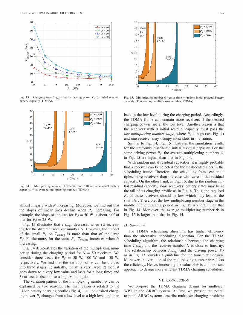
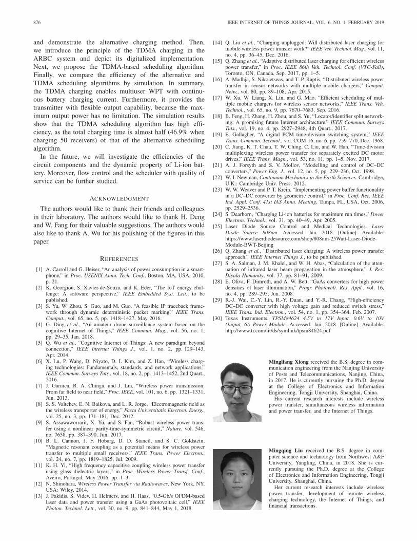
Fig. 14. Multiplexing number ψ versus time t (0 initial residual batterycapacity, � is average multiplexing number, TDMA).
almost linearly with N increasing. Moreover, we find out thatthe slopes of linear lines decline when Pd increasing. Forexample, the slope of the line for Pd = 50 W is about half ofthat for Pd = 25 W.
Fig. 13 illustrates that Tcharge decreases when Pd increas-ing for the different receiver number N. However, the impactof the small Pd on Tcharge is more than that of the largePd. Furthermore, for the same Pd, Tcharge increases when Nincreasing.
Fig. 14 demonstrates the variation of the multiplexing num-ber ψ during the charging period for N = 50 receivers. Weconsider three cases for Pd = 50 W, 100 W, and 150 W,respectively. We find that the variation of ψ can be dividedinto three stages: 1) initially, the ψ is very large; 2) then, itgoes down to a very low value and lasts for a long time; and3) at last, it rises up to a high value again.
The variation pattern of the multiplexing number ψ can beexplained by two reasons. The first reason is related to theLi-ion battery charging profile (Fig. 4), i.e., the desired charg-ing power Pc changes from a low level to a high level and then
Fig. 15. Multiplexing number ψ versus time t (random initial residual batterycapacity, � is average multiplexing number, TDMA).
back to the low level during the charging period. Accordingly,the TDMA frame can contain more receivers if the desiredcharging powers are at the low level. Another reason is thatthe receivers with 0 initial residual capacity must pass thelow multiplexing number stage, where Pc is high (see Fig. 4)and one receiver may occupy most slots in the frame.
Similar to Fig. 14, Fig. 15 illustrates the simulation resultsfor the uniformly distributed initial residual capacity. For thesame driving power Pd, the average multiplexing numbers �in Fig. 15 are higher than that in Fig. 14.
With random initial residual capacities, it is highly probablethat a receiver can be selected for the unallocated slots in thescheduling frame. Therefore, the scheduling frame can mul-tiplex more receivers than the case with zero initial residualcapacity. On the other hand, in Fig. 15, due to the random ini-tial residual capacity, some receivers’ battery states may be atthe tail of its charging profile as in Fig. 4. Thus, the requiredPc of these receivers should be low, which may lead to thesmall Nc. Therefore, the low multiplexing number stage in themiddle of the charging period in Fig. 15 is shorter than thatin Fig. 14. Moreover, the average multiplexing number � inFig. 15 is larger than that in Fig. 14.
D. Summary
The TDMA scheduling algorithm has higher efficiencythan the alternative scheduling algorithm. For the TDMAscheduling algorithm, the relationship between the chargingtime Tcharge and the receiver number N is close to linearity.The relationship between Tcharge and the driving power Pd
as in Fig. 13 provides a guideline for the transmitter design.Moreover, the variation of the multiplexing number ψ reflectsthe efficiency. Hence, increasing the value of ψ is an importantapproach to design more efficient TDMA charging schedulers.
VI. CONCLUSION
We propose the TDMA charging design for multiuserWPT in the ARBC system. At first, we present the point-to-point ARBC system; describe multiuser charging problem;
876 IEEE INTERNET OF THINGS JOURNAL, VOL. 6, NO. 1, FEBRUARY 2019
and demonstrate the alternative charging method. Then,we introduce the principle of the TDMA charging in theARBC system and depict its digitalized implementation.Next, we propose the TDMA-based scheduling algorithm.Finally, we compare the efficiency of the alternative andTDMA scheduling algorithms by simulation. In summary,the TDMA charging enables multiuser WPT with continu-ous battery charging current. Furthermore, it provides thetransmitter with flexible output capability, because the max-imum output power has no limitation. The simulation resultsshow that the TDMA scheduling algorithm has high effi-ciency, as the total charging time is almost half (46.9% whencharging 50 receivers) of that of the alternative schedulingalgorithm.
In the future, we will investigate the efficiencies of thecircuit components and the dynamic property of Li-ion bat-tery. Moreover, flow control and the scheduler with quality ofservice can be further studied.
ACKNOWLEDGMENT
The authors would like to thank their friends and colleaguesin their laboratory. The authors would like to thank H. Dengand W. Fang for their valuable suggestions. The authors wouldalso like to thank A. Wu for his polishing of the figures in thispaper.
REFERENCES
[1] A. Carroll and G. Heiser, “An analysis of power consumption in a smart-phone,” in Proc. USENIX Annu. Tech. Conf., Boston, MA, USA, 2010,p. 21.
[2] K. Georgiou, S. Xavier-de-Souza, and K. Eder, “The IoT energy chal-lenge: A software perspective,” IEEE Embedded Syst. Lett., to bepublished.
[3] S. Yu, W. Zhou, S. Guo, and M. Guo, “A feasible IP traceback frame-work through dynamic deterministic packet marking,” IEEE Trans.Comput., vol. 65, no. 5, pp. 1418–1427, May 2016.
[4] G. Ding et al., “An amateur drone surveillance system based on thecognitive Internet of Things,” IEEE Commun. Mag., vol. 56, no. 1,pp. 29–35, Jan. 2018.
[5] Q. Wu et al., “Cognitive Internet of Things: A new paradigm beyondconnection,” IEEE Internet Things J., vol. 1, no. 2, pp. 129–143,Apr. 2014.
[6] X. Lu, P. Wang, D. Niyato, D. I. Kim, and Z. Han, “Wireless charg-ing technologies: Fundamentals, standards, and network applications,”IEEE Commun. Surveys Tuts., vol. 18, no. 2, pp. 1413–1452, 2nd Quart.,2016.
[7] J. Garnica, R. A. Chinga, and J. Lin, “Wireless power transmission:From far field to near field,” Proc. IEEE, vol. 101, no. 6, pp. 1321–1331,Jun. 2013.
[8] S. S. Valtchev, E. N. Baikova, and L. R. Jorge, “Electromagnetic field asthe wireless transporter of energy,” Facta Universitatis Electron. Energ.,vol. 25, no. 3, pp. 171–181, Dec. 2012.
[9] S. Assawaworrarit, X. Yu, and S. Fan, “Robust wireless power trans-fer using a nonlinear parity-time-symmetric circuit,” Nature, vol. 546,no. 7658, pp. 387–390, Jun. 2017.
[10] B. L. Cannon, J. F. Hoburg, D. D. Stancil, and S. C. Goldstein,“Magnetic resonant coupling as a potential means for wireless powertransfer to multiple small receivers,” IEEE Trans. Power Electron.,vol. 24, no. 7, pp. 1819–1825, Jul. 2009.
[11] K. H. Yi, “High frequency capacitive coupling wireless power transferusing glass dielectric layers,” in Proc. Wireless Power Transf. Conf.,Aveiro, Portugal, May 2016, pp. 1–3.
[12] N. Shinohara, Wireless Power Transfer via Radiowaves. New York, NY,USA: Wiley, 2014.
[13] J. Fakidis, S. Videv, H. Helmers, and H. Haas, “0.5-Gb/s OFDM-basedlaser data and power transfer using a GaAs photovoltaic cell,” IEEEPhoton. Technol. Lett., vol. 30, no. 9, pp. 841–844, May 1, 2018.
[14] Q. Liu et al., “Charging unplugged: Will distributed laser charging formobile wireless power transfer work?” IEEE Veh. Technol. Mag., vol. 11,no. 4, pp. 36–45, Dec. 2016.
[15] Q. Zhang et al., “Adaptive distributed laser charging for efficient wirelesspower transfer,” in Proc. IEEE 86th Veh. Technol. Conf. (VTC-Fall),Toronto, ON, Canada, Sep. 2017, pp. 1–5.
[16] A. Madhja, S. Nikoletseas, and T. P. Raptis, “Distributed wireless powertransfer in sensor networks with multiple mobile chargers,” Comput.Netw., vol. 80, pp. 89–108, Apr. 2015.
[17] W. Xu, W. Liang, X. Lin, and G. Mao, “Efficient scheduling of mul-tiple mobile chargers for wireless sensor networks,” IEEE Trans. Veh.Technol., vol. 65, no. 9, pp. 7670–7683, Sep. 2016.
[18] B. Feng, H. Zhang, H. Zhou, and S. Yu, “Locator/identifier split network-ing: A promising future Internet architecture,” IEEE Commun. SurveysTuts., vol. 19, no. 4, pp. 2927–2948, 4th Quart., 2017.
[19] E. Gallagher, “A digital PCM time-division switching system,” IEEETrans. Commun. Technol., vol. COM-16, no. 6, pp. 759–770, Dec. 1968.
[20] C. Jiang, K. T. Chau, T. W. Ching, C. Liu, and W. Han, “Time-divisionmultiplexing wireless power transfer for separately excited DC motordrives,” IEEE Trans. Magn., vol. 53, no. 11, pp. 1–5, Nov. 2017.
[21] A. J. Forsyth and S. V. Mollov, “Modelling and control of DC–DCconverters,” Power Eng. J., vol. 12, no. 5, pp. 229–236, Oct. 1998.
[22] W. I. Newman, Continuum Mechanics in the Earth Sciences. Cambridge,U.K.: Cambridge Univ. Press, 2012.
[23] W. W. Weaver and P. T. Krein, “Implementing power buffer functionalityin a DC–DC converter by geometric control,” in Proc. Conf. Rec. IEEEInd. Appl. Conf. 41st IAS Annu. Meeting, Tampa, FL, USA, Oct. 2006,pp. 2529–2536.
[24] S. Dearborn, “Charging Li-ion batteries for maximum run times,” PowerElectron. Technol., vol. 31, pp. 40–49, Apr. 2005.
[25] Laser Diode Source Control and Medical Technologies. LaserDiode Source—808nm. Accessed: Jan. 2018. [Online]. Available:https://www.laserdiodesource.com/shop/808nm-25Watt-Laser-Diode-Module-BWT-Beijing
[26] Q. Zhang et al., “Distributed laser charging: A wireless power transferapproach,” IEEE Internet Things J., to be published.
[27] S. A. Salman, J. M. Khalel, and W. H. Abas, “Calculation of the atten-uation of infrared laser beam propagation in the atmosphere,” J. Res.Diyala Humanity, vol. 37, pp. 81–91, 2009.
[28] E. Oliva, F. Dimroth, and A. W. Bett, “GaAs converters for high powerdensities of laser illumination,” Progr. Photovolt. Res. Appl., vol. 16,no. 4, pp. 289–295, Jun. 2008.
[29] R.-J. Wai, C.-Y. Lin, R.-Y. Duan, and Y.-R. Chang, “High-efficiencyDC–DC converter with high voltage gain and reduced switch stress,”IEEE Trans. Ind. Electron., vol. 54, no. 1, pp. 354–364, Feb. 2007.
[30] Texas Instruments. TPSM84624 4.5V to 17V Input, 0.6V to 10VOutput, 6A Power Module. Accessed: Jan. 2018. [Online]. Available:http://www.ti.com/lit/ds/symlink/tpsm84624.pdf
Mingliang Xiong received the B.S. degree in com-munication engineering from the Nanjing Universityof Posts and Telecommunications, Nanjing, China,in 2017. He is currently pursuing the Ph.D. degreeat the College of Electronics and InformationEngineering, Tongji University, Shanghai, China.
His current research interests include wirelesspower transfer, simultaneous wireless informationand power transfer, and the Internet of Things.
Mingqing Liu received the B.S. degree in com-puter science and technology from Northwest A&FUniversity, Yangling, China, in 2018. She is cur-rently pursuing the Ph.D. degree at the Collegeof Electronics and Information Engineering, TongjiUniversity, Shanghai, China.
Her current research interests include wirelesspower transfer, development of remote wirelesscharging technology, the Internet of Things, andfinancial transactions.
XIONG et al.: TDMA IN ARBC FOR IoT DEVICES 877
Qingqing Zhang (S’16) received the M.E. degreein computer science and technology from the HunanUniversity of Technology, Zhuzhou, China, in 2016.She is currently pursuing the Ph.D. degree at theCollege of Electronics and Information Engineering,Tongji University, Shanghai, China.
Her current research interests include wirelesscharge, wireless power transfer, simultaneous wire-less information and power transmission, the Internetof Things, and communications.
Qingwen Liu (M’07–SM’15) received the B.S.degree in electrical engineering and informa-tion science from the University of Science andTechnology of China, Hefei, China, in 2001, andthe M.S. and Ph.D. degrees from the Departmentof Electrical and Computer Engineering, Universityof Minnesota, Minneapolis, MN, USA, in 2003 and2006, respectively.
He is currently a Professor with the Collegeof Electronics and Information Engineering, TongjiUniversity, Shanghai, China. His current research
interests include wireless power transfer and the Internet of Things.
Jun Wu (M’03–SM’14) received the B.S. degreein information engineering and M.S. degree incommunication and electronic systems from XidianUniversity, Xi’an, China, in 1993 and 1996, respec-tively, and the Ph.D. degree in signal and infor-mation processing from the Beijing University ofPosts and Telecommunications, Beijing, China, in1999.
He was a Principal Scientist with Huawei,Shenzhen, China, and Broadcom, Irvine, CA, USA.In 2010, he joined the College of Electronics and
Information Engineering, Tongji University, Shanghai, China, as a Professor.His current research interests include wireless communication, informationtheory, and multimedia signal processing.
Pengfei Xia received the Ph.D. degree from theDepartment of Electrical and Computer Engineering,University of Minnesota Twin Cities, Minneapolis,MN, USA, in 2005.
He is currently a Full Chair Professor withthe College of Electronics and Information, TongjiUniversity, Shanghai, China. He co-edited 60 GHzTechnology for Gb/s WLAN and WPAN: FromTheory to Practice (Wiley, 2010). His currentresearch interests include wireless communications,networks, and signal processing.
Dr. Xia was a co-recipient of the IEEE Signal Processing SocietyBest Paper Award in 2011. He currently serves as a Signal Processingfor Communications (SPCOM) Technical Committee member and SPCOMIndustrial/Government Subcommittee Chair for the IEEE Signal ProcessingSociety.