Embed Size (px)
Citation preview

1
800 HP/500 TON
700 HP/500 TON700 HP/500 TON
800 HP/500 TON
Top DriveDrillingSystem
TechnicalBulletin
TDS-11SA
Top DriveDrillingSystem
TechnicalBulletin
or
April 1998Rev. A

2
3
Top Drive Drilling SystemTDS-11SA
April, 1998
Technical BulletinThis document contains information, and such information may not be disclosed to others for any purpose,nor used for manufacturing purposes without written permission from VARCO International, Incorporated
Other Varco Offices:
Moscow,Russian Federation
Beijing,People's Republic of China
Edmonton,Alberta, Canada
Abu Dhabi,United Arab Emirates
Varco Drilling Systems:
743 North Eckhoff Street,Orange, California 92868, U.S.A.
Tel. (714) 978-1900Fax. (714) 937-5029
12950 West Little York Street,Houston, Texas 77041, U.S.A.
Tel. (713) 937-5500Fax. (713) 937-5095
Forties Road,Montrose, DD10 9ET, Scotland
Tel. 44-1674-677222Fax. 44-1674-677379
No. 8 Sixth Lok Yang Road,Jurong, Singapore 2262
Tel. 65-265-5066Fax. 65-264-0578
Perth,Australia
Lafayette,Louisiana
4
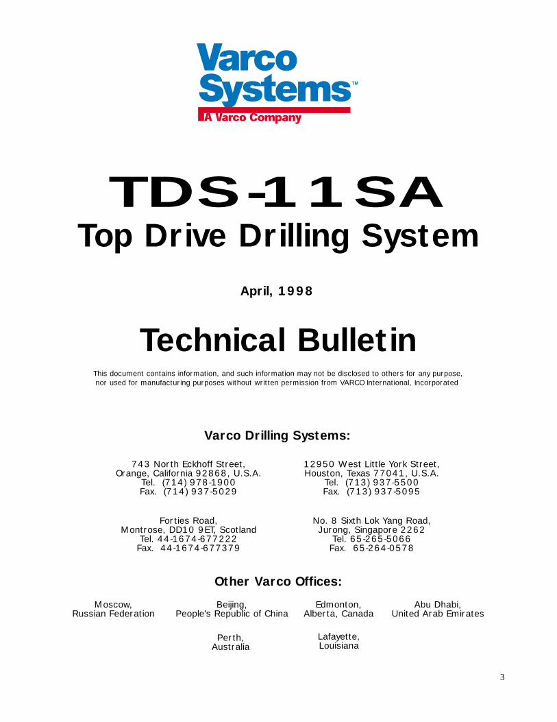
TDS-11SA Top Drive Drilling System
5
Contents
Section 1Introduction .................................................................................. 7
Introduction to the TDS-11SA ........................................................................................................ 7
Breakthroughs in drilling technology ............................................................................................... 8
Section 2Description .................................................................................. 11
TDS-11SA Major components ...................................................................................................... 11
Motor housing and swivel assembly ......................................................................................... 13
Motor cooling system .............................................................................................................. 17
Carriage and guide beam.......................................................................................................... 18
PH-50 pipehandler .................................................................................................................. 20
Hydraulic control system ......................................................................................................... 26
AC motors and control system ................................................................................................. 29
Section 3Operation .................................................................................... 31
Driller’s interface and driller’s console ............................................................................................ 31
Variable frequency inverter ............................................................................................................ 34
Service loop ................................................................................................................................... 36
Contents
6 Contents
Drilling ahead ................................................................................................................................ 36
Drilling ahead with triples ....................................................................................................... 36
Drilling ahead with singles ....................................................................................................... 38
Tripping in and tripping out.................................................................................................... 40
Back reaming ........................................................................................................................... 40
Well control procedures ........................................................................................................... 42
Running casing ........................................................................................................................ 42
Section 4Installation................................................................................... 45
Installing the TDS-11SA ............................................................................................................... 45
Section 5Specifications ............................................................................... 55
Section 6Appendix ..................................................................................... 57
7
Section 1
Introduction
Introduction to the TDS-11SA
Varco Drilling Systems acknowledges the accelerating demand for increased productivity in landdrilling operations and has responded to this growing market with the development of theinnovative TDS-11SA Top Drive Drilling System.
Varco engineering has made use of the recent advancements in AC technology by designing theTDS-11SA to be powered by two AC drilling motors (either 400 or 350 hp each, depending onthe configuration). These 800-hp and 700-hp systems produce 32,500 and 37,500 ft lb ofdrilling torque respectively. They can provide 47,000 and 55,000 ft lb of make-up/break-outtorque respectively.
The TDS-11SA is compact enough to operate safely in a standard 142' mast while providing 500tons of hoisting capacity. Its highly portable design allows for rig-up and rig-down in just a fewhours. It easily integrates into existing rigs at minimal installation cost and minimal rigmodification.

8
Breakthroughs in drilling technology
In today’s competitive land and offshore drilling markets, improving productivity by reducingcost per well is a top priority to operators in both horizontal and vertical drilling programs. Lowmaintenance, quick portability, reduced downtime and low acquisition costs are primeconsiderations for drilling contractors who strive to reduce the cost per well. Varco has produceda top drive system to meet all of these needs.
Increase productivity and reduce the cost per well
The following TDS-11SA features describe how this drilling system will help you increaseproductivity and reduce the cost per well:
❏ AC motors have no brushes, brush gear, or commutator—reducing maintenance costs. Addi-tionally, AC motors have no arcing devices.
❏ The TDS-11SA has an onboard hydraulics system that eliminates the need for a stand-alonehydraulic power unit and fluid service loop—further reducing accessory costs.
❏ The two AC motors, the Varco integrated swivel, and the new rig-up and rig-downtechniques reduce downtime while providing the most compact and portable drillingpackage available on the market today.
❏ The two motors and the drive train provide a redundant power path, increasing the lifeexpectancy of these components. This also reduces downtime and maintenance costs.
❏ The TDS-11SA features a hydraulic link tilt that can tilt the elevator to either side of wellcenter.
❏ The TDS-11SA is specifically built for quick portability.
❏ The TDS-11SA uses helical gearing to reduce noise.
❏ A higher speed (550 rpm max.) TDS-11SA is available.

9
The TDS-11SA has all of the benefits the big top drives have
All of the operational benefits, cost savings and proven time savings realized by utilizing a topdrive hold true with this smaller, less expensive unit. The TDS-11SA will provide drillingcontractors with all of the benefits of a big top drive:
❏ Drilling ahead with 93' stands
❏ Eliminating two out of every three connections
❏ Back reaming and forward reaming capabilities
❏ Full rotation and circulation when tripping out
❏ Pulling through tight spots
❏ Reducing the incidence of stuck pipe
❏ Controlling stand connections
❏ Making and breaking connections with the top drive
❏ Drilling through bridges and tight spots without picking up a kelly
❏ Well control
❏ Instant stabbing and well shut-in at any position in the mast when tripping
❏ Crew safety
❏ Only smooth drill pipe rotating on the rig floor.
❏ Operators only need a backup tong
❏ Reduced power generation costs by using smaller diesel generator sets; and reduced fuelconsumption.
The TDS-11SA, from the innovators at Varco Drilling Systems, incorporates state-of-the arttechnology in the most important innovation in drilling since the rotary table.
The following product information describes the mechanical, electrical, and hydraulic systems ofthe TDS-11SA, as well as operational and installation information to help clarify the benefits re-alized by utilizing the Varco TDS-11SA top drive.
10
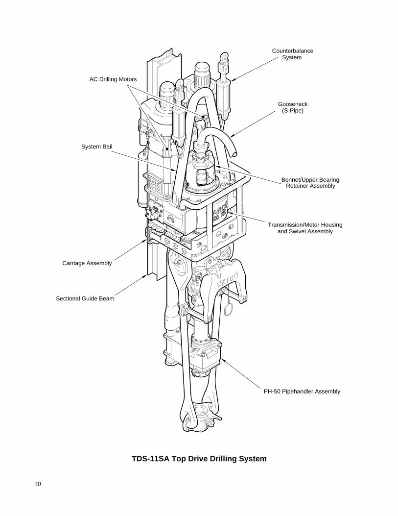
AC Drilling Motors
Sectional Guide Beam
Carriage Assembly
PH-50 Pipehandler Assembly
System Bail
Bonnet/Upper BearingRetainer Assembly
Gooseneck(S-Pipe)
CounterbalanceSystem
Transmission/Motor Housingand Swivel Assembly
TDS-11SA Top Drive Drilling System

11
Section 2
Description
TDS-11SA Major components
The TDS-11SA drilling system includes the following main assemblies and subassemblies:
❏ Motor housing and swivel assembly
❏ Motor cooling system
❏ Carriage and guide beam
❏ PH-50 pipehandler
❏ Hydraulic control system
❏ Counterbalance system
❏ AC drilling motors and control system
12
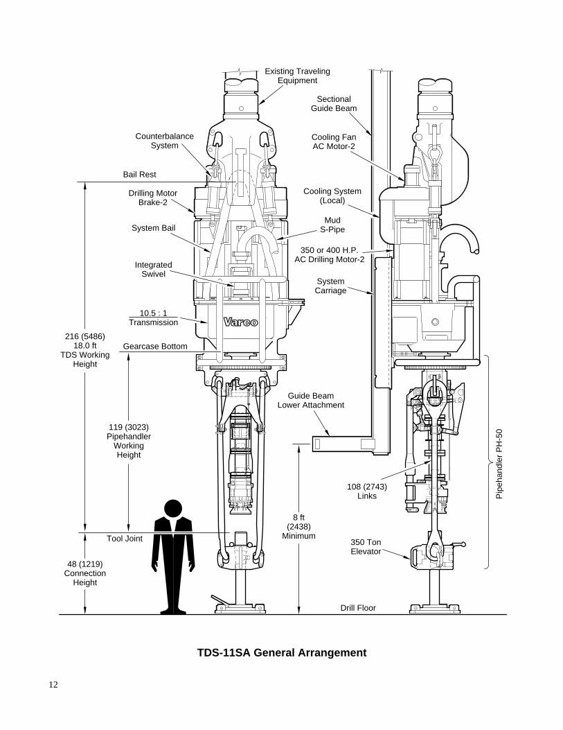
CounterbalanceSystem
Drilling MotorBrake-2
SectionalGuide Beam
Cooling FanAC Motor-2
Cooling System(Local)
350 or 400 H.P.AC Drilling Motor-2
SystemCarriage
MudS-Pipe
Guide BeamLower Attachment
108 (2743)Links
350 TonElevator
Pip
ehan
dler
PH
-50
Existing TravelingEquipment
System Bail
IntegratedSwivel
216 (5486)18.0 ft
TDS WorkingHeight
119 (3023)Pipehandler
WorkingHeight
48 (1219)Connection
Height
8 ft(2438)
Minimum
10.5 : 1Transmission
Tool Joint
Gearcase Bottom
Bail Rest
Drill Floor
TDS-11SA General Arrangement
13
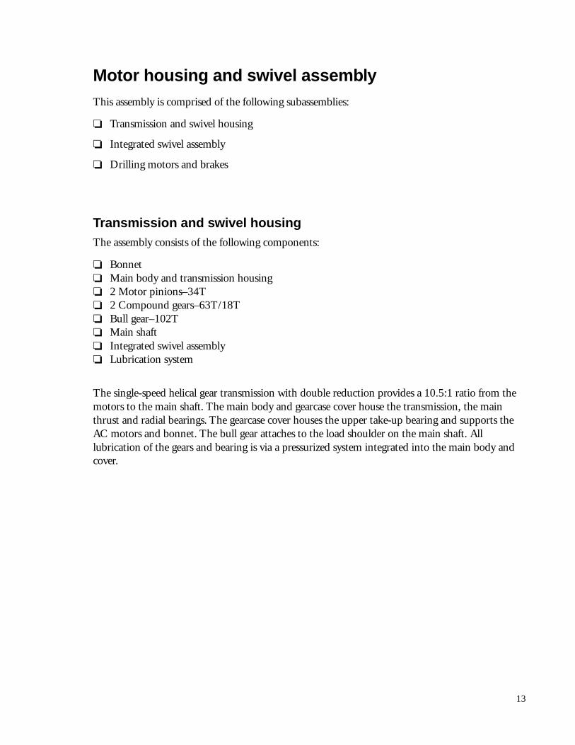
Motor housing and swivel assemblyThis assembly is comprised of the following subassemblies:
❏ Transmission and swivel housing
❏ Integrated swivel assembly
❏ Drilling motors and brakes
Transmission and swivel housingThe assembly consists of the following components:
❏ Bonnet❏ Main body and transmission housing❏ 2 Motor pinions–34T❏ 2 Compound gears–63T/18T❏ Bull gear–102T❏ Main shaft❏ Integrated swivel assembly❏ Lubrication system
The single-speed helical gear transmission with double reduction provides a 10.5:1 ratio from themotors to the main shaft. The main body and gearcase cover house the transmission, the mainthrust and radial bearings. The gearcase cover houses the upper take-up bearing and supports theAC motors and bonnet. The bull gear attaches to the load shoulder on the main shaft. Alllubrication of the gears and bearing is via a pressurized system integrated into the main body andcover.
14
Overall Reduction
10.5 : 1
5 HP AC Cooling Fan Motor (2)
Cooling System
Hydraulic Brake (2)
350 HP or 400 HP ACDrilling Motor (2)
34 Tooth MotorPinion Gear (2)
Gearcase
63x18 Tooth Compound Gear (2)
One-piece Drive Stem
System Bail
Bonnet
500 Ton SwivelThrust Bearing
102 Tooth Bull Gear
TDS-11SA Power train cutaway
15
Integrated swivel assemblyThe main body and transmission housing provide a sealed oil lubrication reservoir for the gearsand bearings. An oil pump, integrated into the housing and powered by a hydraulic motor, feedsthe bearings and gears. The filtered lubrication oil constantly circulates through the main thrustbearing, upper taper bearing, lower radial and compound gear bearing, and over the gear meshes.
An industry-standard washpipe packing assembly is located between the main shaft andgooseneck, and allows for the rotation of the drill string. The bonnet supports the assembly andattaches to the gearcase to provide lateral support.
A swivel bail of forged alloy steel attaches to the main body with bail pins. It swings forward toattach to standard drilling hooks. The bail is fitted into the main body with grease-lubricatedbronze bushings. An extended length is available to allow operator clearance between thegooseneck and hook for wireline packing assemblies.
16
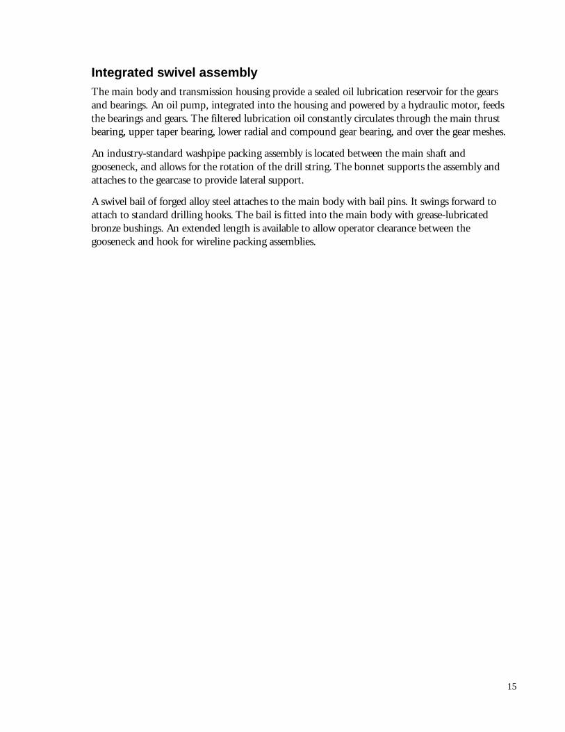
Drilling motors and brakesTwo 400-hp or two 350-hp AC drilling motors supply power to the TDS-11SA. The motorsmount vertically side by side on top of the transmission gearcase cover with a modified “D-face”to avoid shimming or special alignment during installation of the motors.
Each motor has a double-ended shaft with a drive pinion mounted on the lower end and a discbrake rotor mounted on the upper end. Two hydraulic caliper disc brakes mount to the top endof each motor, where they can be easily inspected and serviced via the access covers around thebrake covers. The caliper disc brakes also assist in drill string positioning when performingdirectional work. They are remotely operated from the driller’s console.
Calipers and Shoes
Brake Disc
TDS-11SA Disk Brake
17
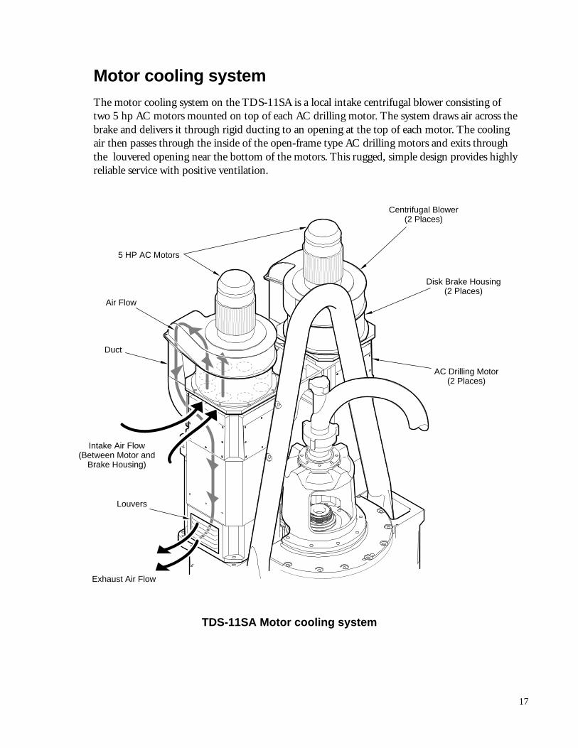
Motor cooling systemThe motor cooling system on the TDS-11SA is a local intake centrifugal blower consisting oftwo 5 hp AC motors mounted on top of each AC drilling motor. The system draws air across thebrake and delivers it through rigid ducting to an opening at the top of each motor. The coolingair then passes through the inside of the open-frame type AC drilling motors and exits throughthe louvered opening near the bottom of the motors. This rugged, simple design provides highlyreliable service with positive ventilation.
5 HP AC Motors
Louvers
Air Flow
Duct
Centrifugal Blower(2 Places)
Disk Brake Housing(2 Places)
AC Drilling Motor(2 Places)
Intake Air Flow(Between Motor and
Brake Housing)
Exhaust Air Flow
TDS-11SA Motor cooling system
18
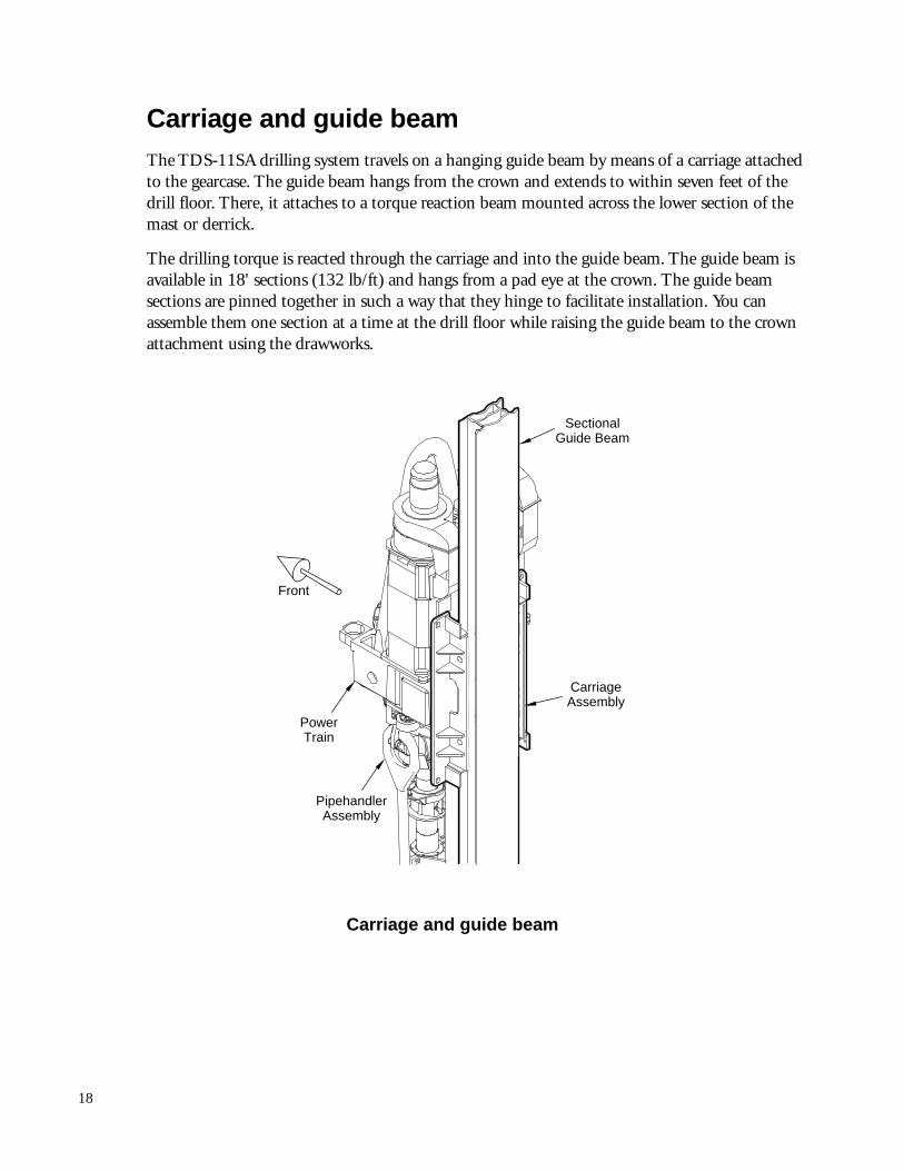
Carriage and guide beamThe TDS-11SA drilling system travels on a hanging guide beam by means of a carriage attachedto the gearcase. The guide beam hangs from the crown and extends to within seven feet of thedrill floor. There, it attaches to a torque reaction beam mounted across the lower section of themast or derrick.
The drilling torque is reacted through the carriage and into the guide beam. The guide beam isavailable in 18' sections (132 lb/ft) and hangs from a pad eye at the crown. The guide beamsections are pinned together in such a way that they hinge to facilitate installation. You canassemble them one section at a time at the drill floor while raising the guide beam to the crownattachment using the drawworks.
SectionalGuide Beam
CarriageAssembly
PowerTrain
Front
PipehandlerAssembly
Carriage and guide beam
19
VARCO
P
5H
0
AV
R
OC
Rotating Link Adapter (Ref.)
Upper IBOPRemote Actuator
Hydraulic CylinderTorque Arrester
Frame
Landing Collar
IBOP ActuatorYoke
Upper IBOP(Remote)
Tool JointLock (3)
Main Shaft
Manual Lower IBOP(Optional)
Saver Sub(Short)
Back-Up ClampAssembly (Ref.)
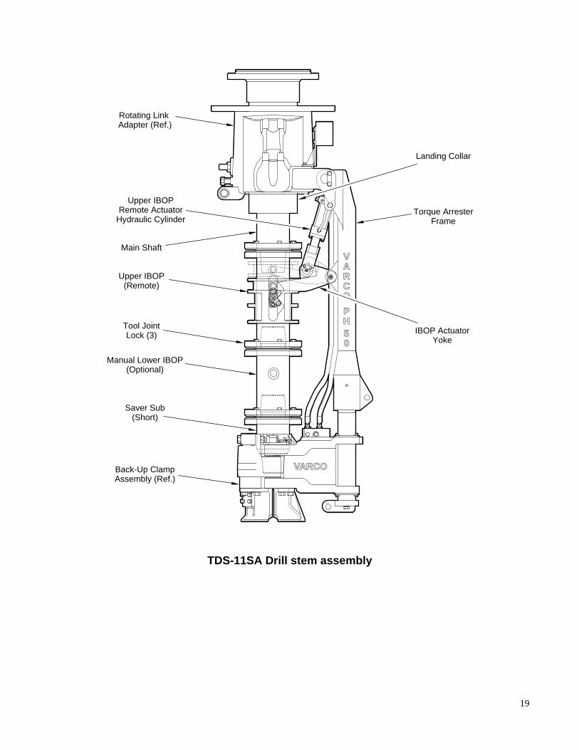
TDS-11SA Drill stem assembly
20
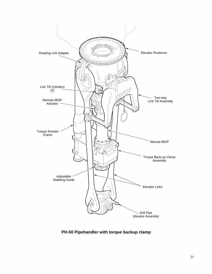
PH-50 pipehandlerThe PH-50 pipehandler consists of the following major components:
❏ Powered rotating head/link adapter
❏ Bidirectional link tilt
❏ Loading collar
❏ Remote upper IBOP actuator
❏ Torque backup clamp
Powered rotating head and rotating link adapterThe powered rotating head/rotating link adapter allow the hydraulic lines to remain connected asthe pipehandler rotates with the drill stem components while tripping out or when positioningthe link tilt.
The powered rotating head/link adapter has a hydraulic drive motor to rotate it in eitherdirection. An electric solenoid valve, connected to a switch on the driller’s console, operates thehydraulic motor. A pinion gear on the hydraulic drive motor rotates the positioning gear that isattached to the top of the rotating link adapter. During make or brake operations the rotatinglink adapter can be locked into any of 24 index positions by selecting the pipehandler clampmode and actuating a hydraulically operated shot pin. When the hydraulic drive motor is notpowered the link adapter can rotate freely.
The link tilt cylinders and the torque arrestor frame hang from the rotating link adapter.
The link adapter is attached to the stem support. The internal hydraulic fluid passages in thestem connect to the respective fluid passages in the rotating link adapter. Fluid is fed from themain manifold into the stem through the radial passages at the upper end. This fluid is routedfrom the stem through its grooves to the link adapter and out to all actuators on the pipehandler. While rotating or in any stationary position, fluid flows between the two components.
21
Rotating Link Adapter
Torque Back-up ClampAssembly
Two-wayLink Tilt Assembly
Elevator Positioner
Remote IBOPActuator
Link Tilt Cylinders(2)
Torque ArresterFrame
AdjustableStabbing Guide
Manual IBOP
Drill PipeElevator Assembly
Elevator Links
PH-50 Pipehandler with torque backup clamp
22
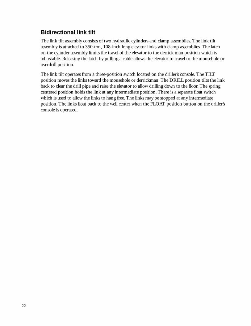
Bidirectional link tiltThe link tilt assembly consists of two hydraulic cylinders and clamp assemblies. The link tiltassembly is attached to 350-ton, 108-inch long elevator links with clamp assemblies. The latchon the cylinder assembly limits the travel of the elevator to the derrick man position which isadjustable. Releasing the latch by pulling a cable allows the elevator to travel to the mousehole oroverdrill position.
The link tilt operates from a three-position switch located on the driller’s console. The TILTposition moves the links toward the mousehole or derrickman. The DRILL position tilts the linkback to clear the drill pipe and raise the elevator to allow drilling down to the floor. The springcentered position holds the link at any intermediate position. There is a separate float switchwhich is used to allow the links to hang free. The links may be stopped at any intermediateposition. The links float back to the well center when the FLOAT position button on the driller’sconsole is operated.
23
108(2743)
76(1930)
Drill Floor
56(1422)
28(711)
Link Tilt Cylinder (2)
Mou
seho
le
Der
rickm
an *
*
Overdrill *D
rill
34(864)
36(914)Typ.
14(356)
4(102)
WellCL
All dimensions are true for108" long Elevator Links and
FOR REFERENCE ONLY
* Typically-90° from MouseholePosition and rotated into view
FOR CLARITY ONLY
** At Monkey Board level (80')and placed into view
FOR CLARITY ONLY
PH-50 Bidirectional link tilt positions
24
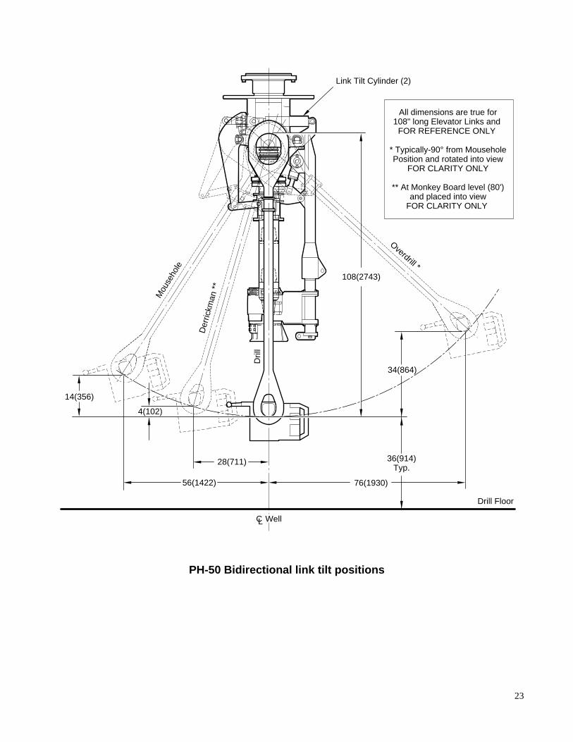
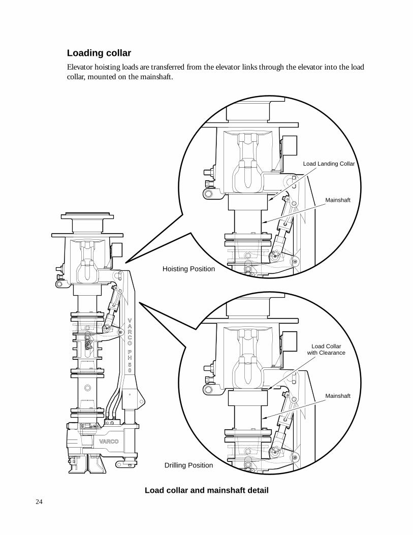
Loading collarElevator hoisting loads are transferred from the elevator links through the elevator into the loadcollar, mounted on the mainshaft.
VARCO
P
5H
0
AV
R
OC
Load Landing Collar
Mainshaft
Load Collarwith Clearance
Drilling Position
Hoisting Position
Mainshaft
Load collar and mainshaft detail
25
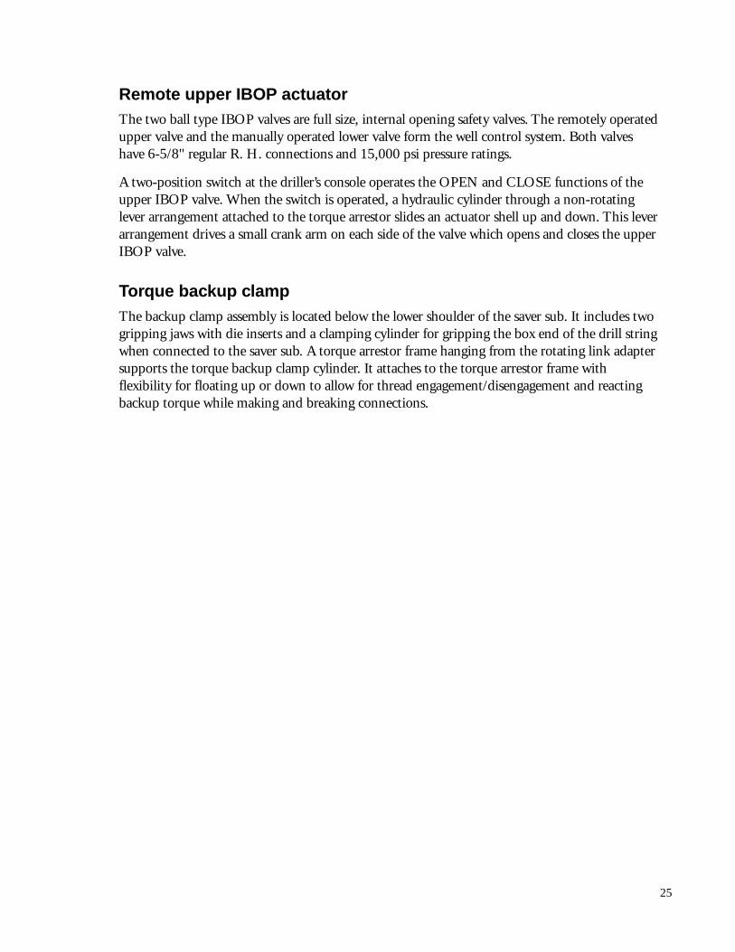
Remote upper IBOP actuatorThe two ball type IBOP valves are full size, internal opening safety valves. The remotely operatedupper valve and the manually operated lower valve form the well control system. Both valveshave 6-5/8" regular R. H. connections and 15,000 psi pressure ratings.
A two-position switch at the driller’s console operates the OPEN and CLOSE functions of theupper IBOP valve. When the switch is operated, a hydraulic cylinder through a non-rotatinglever arrangement attached to the torque arrestor slides an actuator shell up and down. This leverarrangement drives a small crank arm on each side of the valve which opens and closes the upperIBOP valve.
Torque backup clampThe backup clamp assembly is located below the lower shoulder of the saver sub. It includes twogripping jaws with die inserts and a clamping cylinder for gripping the box end of the drill stringwhen connected to the saver sub. A torque arrestor frame hanging from the rotating link adaptersupports the torque backup clamp cylinder. It attaches to the torque arrestor frame withflexibility for floating up or down to allow for thread engagement/disengagement and reactingbackup torque while making and breaking connections.
26
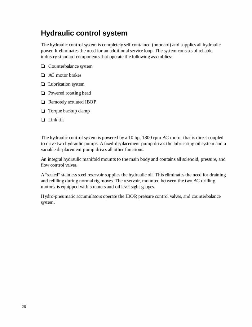
Hydraulic control systemThe hydraulic control system is completely self-contained (onboard) and supplies all hydraulicpower. It eliminates the need for an additional service loop. The system consists of reliable,industry-standard components that operate the following assemblies:
❏ Counterbalance system
❏ AC motor brakes
❏ Lubrication system
❏ Powered rotating head
❏ Remotely actuated IBOP
❏ Torque backup clamp
❏ Link tilt
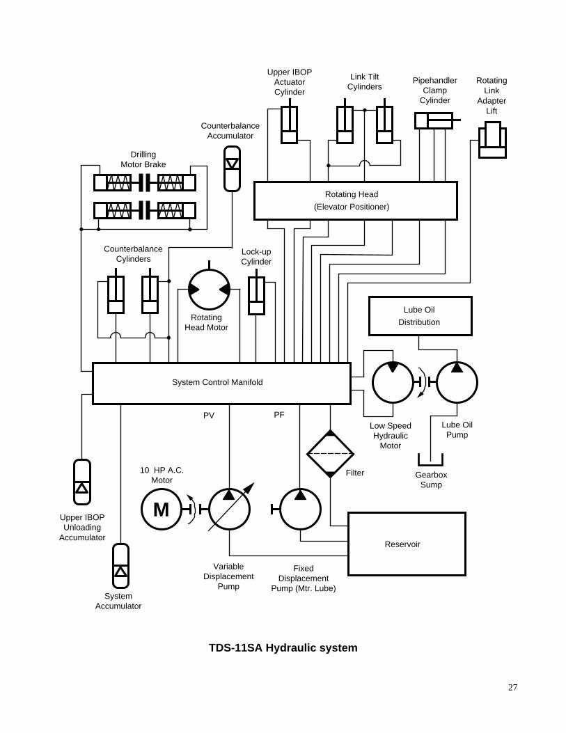
The hydraulic control system is powered by a 10 hp, 1800 rpm AC motor that is direct coupledto drive two hydraulic pumps. A fixed-displacement pump drives the lubricating oil system and avariable displacement pump drives all other functions.
An integral hydraulic manifold mounts to the main body and contains all solenoid, pressure, andflow control valves.
A “sealed” stainless steel reservoir supplies the hydraulic oil. This eliminates the need for drainingand refilling during normal rig moves. The reservoir, mounted between the two AC drillingmotors, is equipped with strainers and oil level sight gauges.
Hydro-pneumatic accumulators operate the IBOP, pressure control valves, and counterbalancesystem.
27
M
Reservoir
FixedDisplacement
Pump (Mtr. Lube)
VariableDisplacement
Pump
10 HP A.C.Motor
RotatingHead Motor
Lock-upCylinder
CounterbalanceAccumulator
DrillingMotor Brake
Upper IBOPActuatorCylinder
Link TiltCylinders
Pipehandler RotatingLink
AdapterLift
ClampCylinder
CounterbalanceCylinders
Lube Oil
Distribution
SystemAccumulator
Lube OilPump
PV PF
Filter
Rotating Head
(Elevator Positioner)
System Control Manifold
Low SpeedHydraulic
Motor
Upper IBOPUnloading
Accumulator
GearboxSump
TDS-11SA Hydraulic system
28
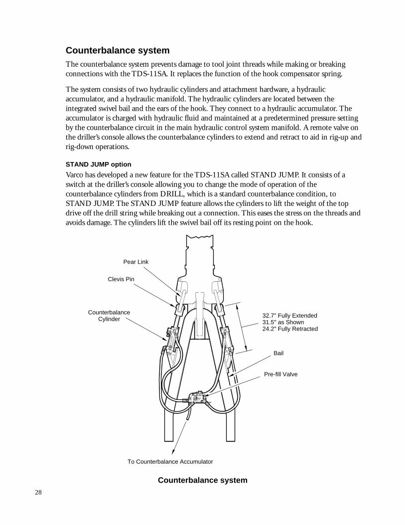
Counterbalance systemThe counterbalance system prevents damage to tool joint threads while making or breakingconnections with the TDS-11SA. It replaces the function of the hook compensator spring.
The system consists of two hydraulic cylinders and attachment hardware, a hydraulicaccumulator, and a hydraulic manifold. The hydraulic cylinders are located between theintegrated swivel bail and the ears of the hook. They connect to a hydraulic accumulator. Theaccumulator is charged with hydraulic fluid and maintained at a predetermined pressure settingby the counterbalance circuit in the main hydraulic control system manifold. A remote valve onthe driller’s console allows the counterbalance cylinders to extend and retract to aid in rig-up andrig-down operations.
STAND JUMP option
Varco has developed a new feature for the TDS-11SA called STAND JUMP. It consists of aswitch at the driller’s console allowing you to change the mode of operation of thecounterbalance cylinders from DRILL, which is a standard counterbalance condition, toSTAND JUMP. The STAND JUMP feature allows the cylinders to lift the weight of the topdrive off the drill string while breaking out a connection. This eases the stress on the threads andavoids damage. The cylinders lift the swivel bail off its resting point on the hook.
Pear Link
Clevis Pin
Bail
Pre-fill Valve
CounterbalanceCylinder
To Counterbalance Accumulator
32.7" Fully Extended31.5" as Shown24.2" Fully Retracted
Counterbalance system
29
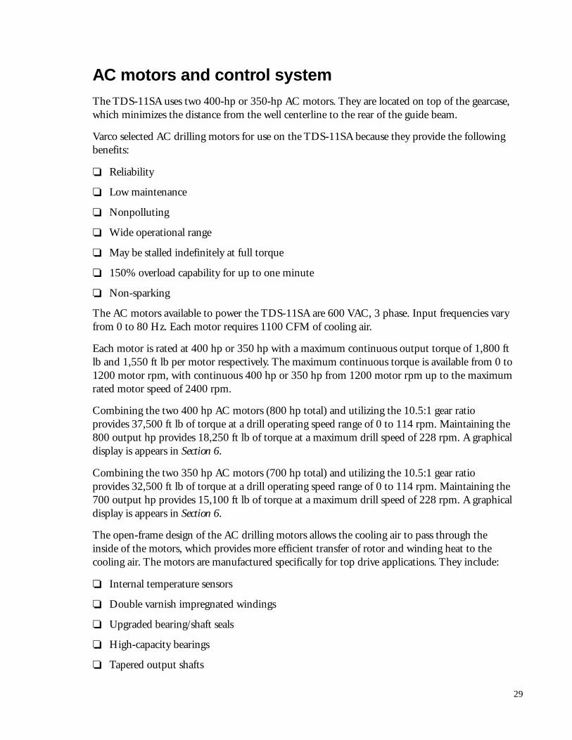
AC motors and control systemThe TDS-11SA uses two 400-hp or 350-hp AC motors. They are located on top of the gearcase,which minimizes the distance from the well centerline to the rear of the guide beam.
Varco selected AC drilling motors for use on the TDS-11SA because they provide the followingbenefits:
❏ Reliability
❏ Low maintenance
❏ Nonpolluting
❏ Wide operational range
❏ May be stalled indefinitely at full torque
❏ 150% overload capability for up to one minute
❏ Non-sparking
The AC motors available to power the TDS-11SA are 600 VAC, 3 phase. Input frequencies varyfrom 0 to 80 Hz. Each motor requires 1100 CFM of cooling air.
Each motor is rated at 400 hp or 350 hp with a maximum continuous output torque of 1,800 ftlb and 1,550 ft lb per motor respectively. The maximum continuous torque is available from 0 to1200 motor rpm, with continuous 400 hp or 350 hp from 1200 motor rpm up to the maximumrated motor speed of 2400 rpm.
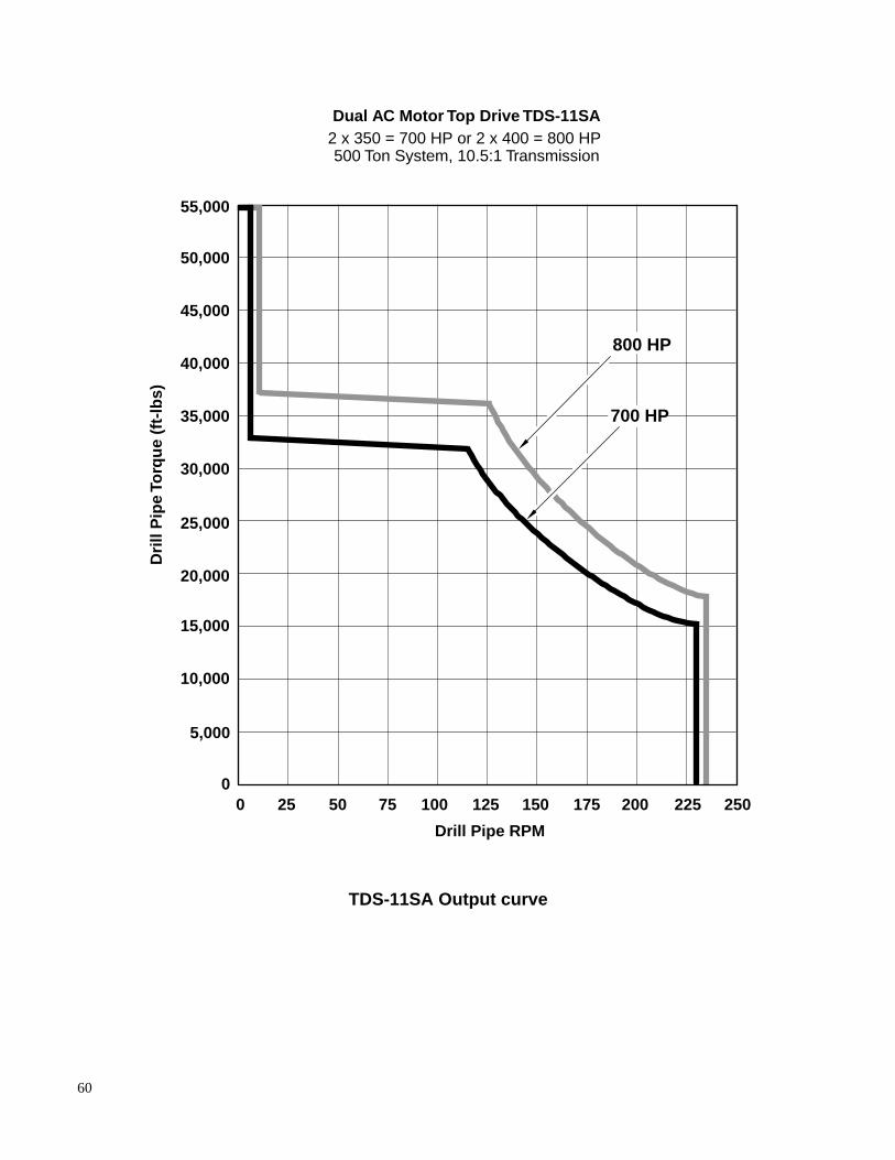
Combining the two 400 hp AC motors (800 hp total) and utilizing the 10.5:1 gear ratioprovides 37,500 ft lb of torque at a drill operating speed range of 0 to 114 rpm. Maintaining the800 output hp provides 18,250 ft lb of torque at a maximum drill speed of 228 rpm. A graphicaldisplay is appears in Section 6.
Combining the two 350 hp AC motors (700 hp total) and utilizing the 10.5:1 gear ratioprovides 32,500 ft lb of torque at a drill operating speed range of 0 to 114 rpm. Maintaining the700 output hp provides 15,100 ft lb of torque at a maximum drill speed of 228 rpm. A graphicaldisplay is appears in Section 6.
The open-frame design of the AC drilling motors allows the cooling air to pass through theinside of the motors, which provides more efficient transfer of rotor and winding heat to thecooling air. The motors are manufactured specifically for top drive applications. They include:
❏ Internal temperature sensors
❏ Double varnish impregnated windings
❏ Upgraded bearing/shaft seals
❏ High-capacity bearings
❏ Tapered output shafts
30
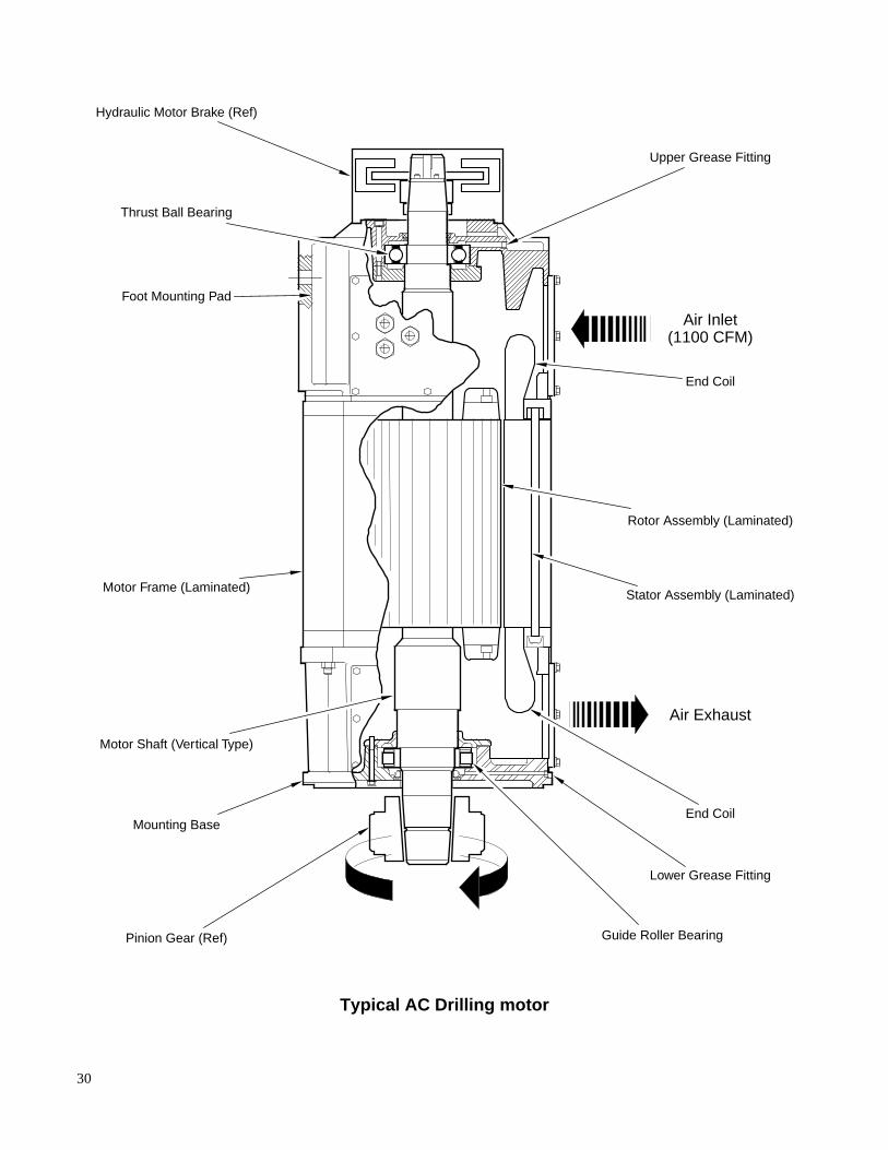
Thrust Ball Bearing
Air Inlet(1100 CFM)
Air Exhaust
Upper Grease Fitting
Lower Grease Fitting
End Coil
End Coil
Guide Roller Bearing
Stator Assembly (Laminated)
Rotor Assembly (Laminated)
Pinion Gear (Ref)
Mounting Base
Motor Frame (Laminated)
Motor Shaft (Vertical Type)
Foot Mounting Pad
Hydraulic Motor Brake (Ref)
Typical AC Drilling motor
31
Section 3
Operation
Driller’s interface and driller’s console
The driller’s console is manufactured from 300-series stainless steel and it uses full-size, oil-tightswitches and indicators. It is designed for purging to meet hazardous area requirements. By re-quest, Varco can supply the console with Pyle-National, U.L., or Ex connectors.
Throttle controlThe throttle uses a design similar to the standard throttle control used with SCR systems. Thehandle is robust and includes integral stops to prevent damage.
Torque controlTwo torque limit potentiometers are provided for setting drill and makeup torque limits.
The drill limit control allows the driller to set the maximum torque output of the top drive tomatch the drill pipe size being used.
The makeup control sets the torque when making up connections using the TDS-11SA drillingmotors.
32
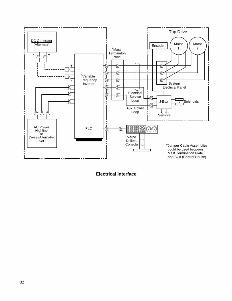
VarcoDriller'sConsole Jumper Cable Assemblies
could be used betweenMast Termination Plateand Skid (Control House).
*
+
-Variable
PLC
FrequencyInverter
AC PowerHighline
orDiesel/Alternator
Set
+-
*
Top Drive
Solenoids
SystemElectrical Panel
ElectricalServiceLoop
Aux. PowerLoop
MastTerminaton
Panel
Sensors
J-Box
Motor2
Motor1
Encoder*
DC Generator(Alternate)
Electrical interface
33
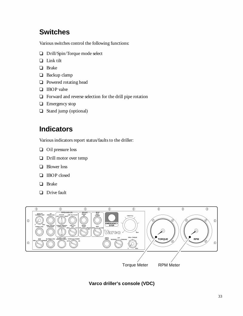
SwitchesVarious switches control the following functions:
❏ Drill/Spin/Torque mode select
❏ Link tilt
❏ Brake
❏ Backup clamp
❏ Powered rotating head
❏ IBOP valve
❏ Forward and reverse selection for the drill pipe rotation
❏ Emergency stop
❏ Stand jump (optional)
IndicatorsVarious indicators report status/faults to the driller:
❏ Oil pressure loss
❏ Drill motor over temp
❏ Blower loss
❏ IBOP closed
❏ Brake
❏ Drive fault
OFF
MAKE-UPCURRENT LIMIT
OILPRESS LOSS LINK TILT FLOAT
DRILL MOTOROVERTEMPPURGE LOSS
TORQUE WRENCHPUSH & HOLD
LINK TILTOFF
BLOWER LOSS
ROTATE
PIPEHANDLER
LEFT
DRILL TILT
RIGHT
SPINDRILL TORQUE
HYDRAULIC POWER
AUTO ON
IBOPCLOSED
ALARMSILENCE
LAMPCHECK
BRAKEON
BRAKEAUTO
DRIVEFAULT
IBOP
IBOPBRAKE
OPEN CLOSEBRAKEON
/ OFF DRILL TORQUE
0
0 MAX
TORQUE RPM
THROTTLE
EMERGENCYSTOP
MAX
0 MAX
REVERSE FORWARD
Torque Meter RPM Meter
Varco driller’s console (VDC)
34
Varco control systemThe driller’s PLC panel is located in the environmentally controlled variable frequency inverterhouse.
It provides an interface between the driller’s console, the variable frequency inverter, and theTDS-11SA. It includes the following components:
❏ Control logic for system interlocks
❏ Blower and oil pump motor starters
❏ Control circuitry for pipehandler functions
❏ Power supply for TDS-11SA solenoids and VDC indicators
Inputs to the variable frequency drive is via serial communications that provide speed and torqueinputs, and on, reverse and emergency stop inputs. Additionally, any changes to alarm orinterlock functions have no effect on the frequency drive. Function changes are implementedwith the same programming tools used on the standard Varco top drive systems.
The control system receives input from the operator controls on the driller’s console andprocesses this information through the programmable logic controller (PLC). It controls theresponses of the cooling system motor, the solenoid valves, the brakes, IBOP functions, andsensors. The control system reads the status of the sensors and acts as an interlock to preventinadvertent tool operations. It notifies the driller of the operational status of the TDS-11SA andprovides a diagnosis of any inadvertent operational conditions.
Variable frequency inverter
The variable frequency inverter (VFI) consists of the following three major sections:
Rectifier or converterIn this section, the incoming 3-phase AC power is converted to DC for use by the power devices.Alternately, by bypassing the rectifier section, the drive can be powered from a 740 VDCgenerator.
35
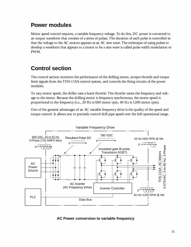
Power modulesMotor speed control requires, a variable frequency voltage. To do this, DC power is converted toan output waveform that consists of a series of pulses. The duration of each pulse is controlled sothat the voltage to the AC motors appears as an AC sine wave. The technique of using pulses todevelop a waveform that appears to a motor to be a sine wave is called pulse width modulation orPWM.
Control sectionThe control section monitors the performance of the drilling motor, accepts throttle and torquelimit signals from the TDS-11SA control system, and controls the firing circuits of the powermodules.
To vary motor speed, the driller uses a hand throttle. The throttle varies the frequency and volt-age to the motor. Because the drilling motor is frequency synchronous, the motor speed isproportional to the frequency (i.e., 20 Hz is 600 motor rpm, 40 Hz is 1200 motor rpm).
One of the greatest advantages of an AC variable frequency drive is the quality of the speed andtorque control. It allows you to precisely control drill pipe speed over the full operational range.
+
-
Variable Frequency Drive
TD
S-1
1SA
AC
Mot
ors
0-57
5VA
C, 0
to 8
0 H
z, 3
-Pha
se
Inverter Controller
Data Bus
Resultant Pulse DC
AC Inverter(AC Frequency Drive)
780 VDC20 Hz=600 RPM @ Mtr.
40 Hz=1200 RPM @ Mtr.
0
0
0
ACPowerSource
PLC
Insulated gate Bi-polarTransistors (IGBT)
00
600 VAC, 42 to 62 Hz3-Phase (733 AMPS Max)
AC Power conversion to variable frequency
36
Service loop
The TDS-11SA has an onboard hydraulic system and, therefore, does not need a fluids serviceloop. This adds to the cost-effectiveness of the TDS-11SA drilling system and provides a saferwork area.
The TDS-11SA service loops consist of power and ground cables, composite cable for all con-ductors for drilling motors and actuators (solenoid) control, and auxiliary power cables. Cableconfigurations are available for portable and fixed applications for U.L. and EEx requirements.
Drilling ahead
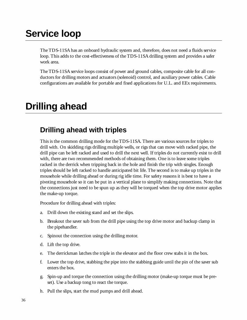
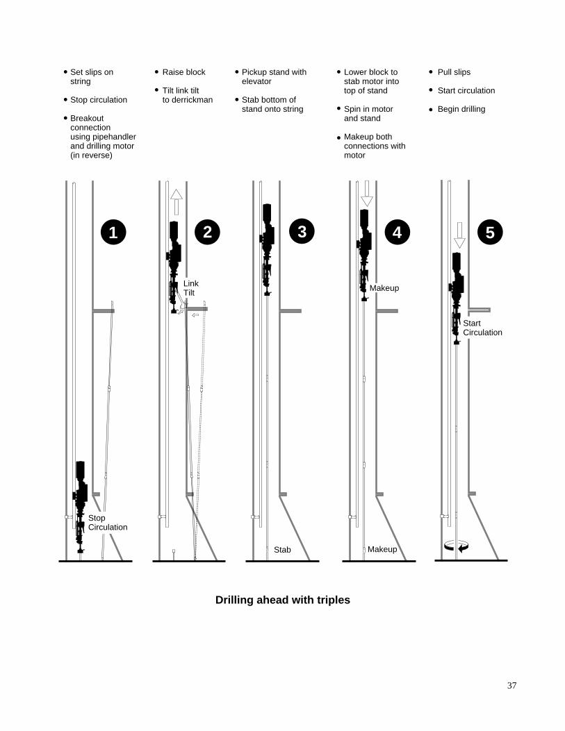
Drilling ahead with triplesThis is the common drilling mode for the TDS-11SA. There are various sources for triples todrill with. On skidding rigs drilling multiple wells, or rigs that can move with racked pipe, thedrill pipe can be left racked and used to drill the next well. If triples do not currently exist to drillwith, there are two recommended methods of obtaining them. One is to leave some triplesracked in the derrick when tripping back in the hole and finish the trip with singles. Enoughtriples should be left racked to handle anticipated bit life. The second is to make up triples in themousehole while drilling ahead or during rig idle time. For safety reasons it is best to have apivoting mousehole so it can be put in a vertical plane to simplify making connections. Note thatthe connections just need to be spun up as they will be torqued when the top drive motor appliesthe make-up torque.
Procedure for drilling ahead with triples:
a. Drill down the existing stand and set the slips.
b. Breakout the saver sub from the drill pipe using the top drive motor and backup clamp inthe pipehandler.
c. Spinout the connection using the drilling motor.
d. Lift the top drive.
e. The derrickman latches the triple in the elevator and the floor crew stabs it in the box.
f. Lower the top drive, stabbing the pipe into the stabbing guide until the pin of the saver subenters the box.
g. Spin-up and torque the connection using the drilling motor (make-up torque must be pre-set). Use a backup tong to react the torque.
h. Pull the slips, start the mud pumps and drill ahead.
37
Set slips onstring
Stop circulation
Breakoutconnectionusing pipehandler and drilling motor(in reverse)
Raise block
Tilt link tiltto derrickman
Pickup stand withelevator
Stab bottom ofstand onto string
Lower block tostab motor intotop of stand
Spin in motorand stand
Makeup bothconnections withmotor
Pull slips
Start circulation
Begin drilling
1 2 3 4 5
Stab Makeup
Makeup
StopCirculation
StartCirculation
LinkTilt
Drilling ahead with triples
38
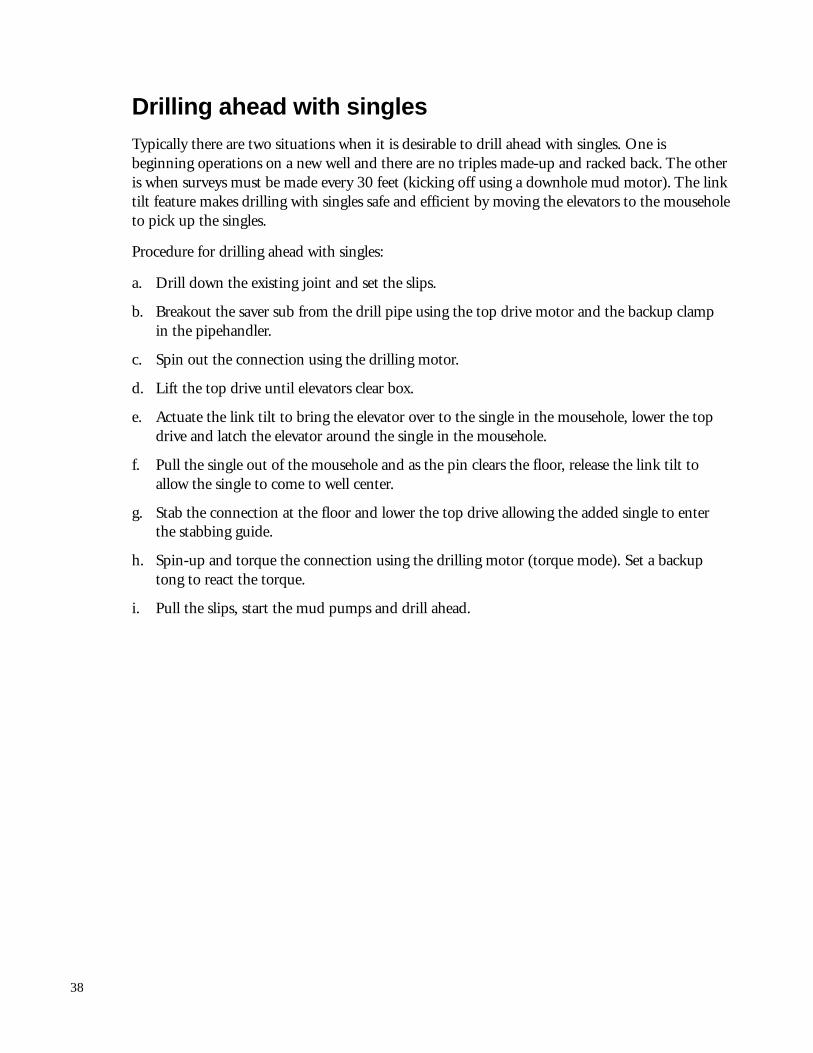
Drilling ahead with singlesTypically there are two situations when it is desirable to drill ahead with singles. One isbeginning operations on a new well and there are no triples made-up and racked back. The otheris when surveys must be made every 30 feet (kicking off using a downhole mud motor). The linktilt feature makes drilling with singles safe and efficient by moving the elevators to the mouseholeto pick up the singles.
Procedure for drilling ahead with singles:
a. Drill down the existing joint and set the slips.
b. Breakout the saver sub from the drill pipe using the top drive motor and the backup clampin the pipehandler.
c. Spin out the connection using the drilling motor.
d. Lift the top drive until elevators clear box.
e. Actuate the link tilt to bring the elevator over to the single in the mousehole, lower the topdrive and latch the elevator around the single in the mousehole.
f. Pull the single out of the mousehole and as the pin clears the floor, release the link tilt toallow the single to come to well center.
g. Stab the connection at the floor and lower the top drive allowing the added single to enterthe stabbing guide.
h. Spin-up and torque the connection using the drilling motor (torque mode). Set a backuptong to react the torque.
i. Pull the slips, start the mud pumps and drill ahead.
39
Set slips onstring
Stop circulation
Close IBOP
Breakoutconnectionusing pipehandler and drilling motor(in reverse)
Tilt links tomousehole
Latch drill pipeelevator aroundsingle
Pickup single withelevator
Release link tilt
Stab bottom ofsingle onto string
Lower block tostab motor intotop of single
Spin in motorand single
Makeup bothconnections with motor intorque mode
Pull slips
Open IBOP
Start circulation
Begin drilling
Stab Makeup
OpenIBOP
LinkTilt
1 2 3 4 5
Makeup
CloseIBOP
Drilling ahead with singles
40
Tripping in and tripping outTripping is handled in the conventional manner. The link tilt feature can be used to tilt theelevator to the derrickman, enhancing his ability to latch it around the pipe thus improving triptimes.
The link tilt has an intermediate stop which is adjustable to set the elevator at a convenientworking distance from the monkey board. The intermediate stop is tilted out of the way to allowthe elevator to reach the mousehole.
The elevator may rotate in any direction from frictional or torque forces realized by the drillstring.
If a tight spot or key seat is encountered while tripping out of the hole, the drilling motor maybe spun into the stand at any height in the derrick and circulation and rotation establishedimmediately to work the pipe through the tight spot.
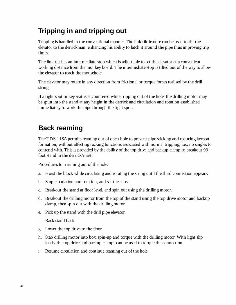
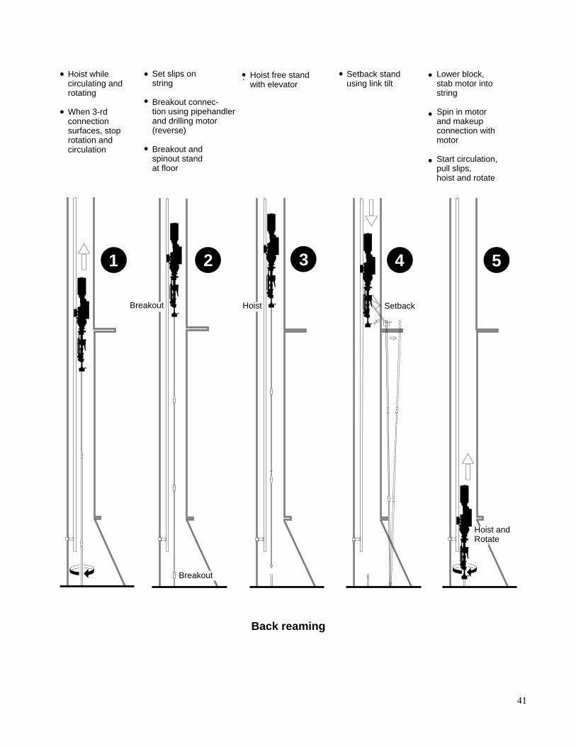
Back reamingThe TDS-11SA permits reaming out of open hole to prevent pipe sticking and reducing keyseatformation, without affecting racking functions associated with normal tripping; i.e., no singles tocontend with. This is provided by the ability of the top drive and backup clamp to breakout 93foot stand in the derrick/mast.
Procedures for reaming out of the hole:
a. Hoist the block while circulating and rotating the string until the third connection appears.
b. Stop circulation and rotation, and set the slips.
c. Breakout the stand at floor level, and spin out using the drilling motor.
d. Breakout the drilling motor from the top of the stand using the top drive motor and backupclamp, then spin out with the drilling motor.
e. Pick up the stand with the drill pipe elevator.
f. Rack stand back.
g. Lower the top drive to the floor.
h. Stab drilling motor into box, spin-up and torque with the drilling motor. With light sliploads, the top drive and backup clamps can be used to torque the connection.
i. Resume circulation and continue reaming out of the hole.
41
Hoist whilecirculating androtating
When 3-rd connectionsurfaces, stoprotation andcirculation
Set slips onstring
Breakout connec-tion using pipehandlerand drilling motor (reverse)
Breakout andspinout standat floor
Hoist free standwith elevator
Setback standusing link tilt
Setback
Lower block,stab motor intostring
Spin in motorand makeupconnection withmotor
Start circulation,pull slips,hoist and rotate
1 2 3 4 5
Breakout
Breakout Hoist
Hoist andRotate
Back reaming
42
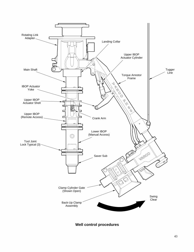
Well control proceduresThe TDS-11SA can stab into the string at any point in the derrick. While drilling, the remotelycontrolled upper IBOP valve is always in the string for immediate use as needed.
The lower IBOP valve is the same type as the upper IBOP valve except it must be operatedmanually with a wrench. Both valves always remain in the string and are therefore always readilyavailable by connecting the TDS-11SA to the drill string.
To attach well control equipment to the drill string the torque arrestor frame assembly can bepulled away from the drill string by opening the clamp cylinder gate.
After removing the lower valve from the upper valve, the lower valve remains connected to thedrill string for well control purposes. The TDS-11SA includes crossover subs for connecting thedrill stem to the lower valve.
Procedure for well control during tripping operations:
a. On indication of a kick, set the slips and stab the top drive into the string.
b. Spin-up and torque connection.
c. Close remote upper IBOP.
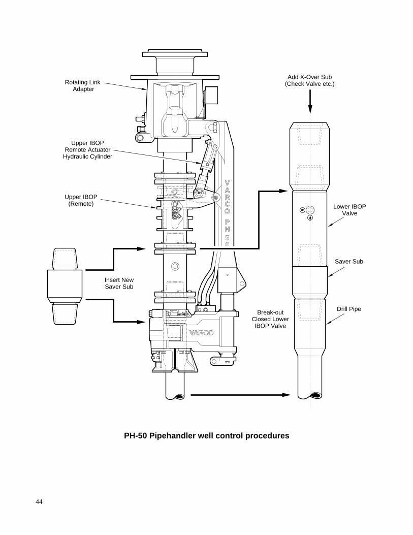
Internal pipe pressure of up to 15,000 psi is now held by the upper IBOP valve. If it becomesnecessary to continue tripping in with a dart valve, or another well control accessory, thelower IBOP valve can be used to assist the operation. In this case, the following steps may befollowed:
d. Lower string to the floor and reset the slips.
e. Manually close the lower IBOP valve.
f. With the tugger line attached to the back of the unit, swing out the torque arrestor clampcylinder assembly.
g. Remove the lower and intermediate tool joint locks.
h. Breakout lower IBOP and saver sub from upper IBOP using tongs.
i. Install appropriate crossover sub, check valve or circulation sub on top of lower IBOP valve.
j. Proceed with normal well control procedures.
Running casingFor casing operations, longer elevator links (180") must be used to allow clearance for cementinghead under the backup clamp in the pipehandler.
Attach a short piece of hose to the saver sub in the pipehandler to fill the casing while lowering.Use the remotely controlled upper IBOP valve to start and stop the fluid flow.
43
VARCO
P
5H
0
AV
R
OC
TuggerLine
Tool JointLock Typical (3)
Saver Sub
Lower IBOP(Manual Access)
Crank Arm
Rotating LinkAdapter
IBOP ActuatorYoke
Main Shaft
Upper IBOP(Remote Access)
Upper IBOPActuator Shell
Clamp Cylinder Gate(Shown Open)
Back-Up ClampAssembly
SwingClear
Torque ArrestorFrame
Upper IBOPActuator Cylinder
Landing Collar
Well control procedures
44
VARCO
P
5H
0
AV
R
OC
Rotating Link Adapter
Upper IBOPRemote Actuator
Hydraulic Cylinder
Upper IBOP(Remote) Lower IBOP
Valve
Insert NewSaver Sub
Break-outClosed LowerIBOP Valve
Add X-Over Sub(Check Valve etc.)
Saver Sub
Drill Pipe
PH-50 Pipehandler well control procedures

45
Section 4
Installation
Installing the TDS-11SA
To install a TDS-11SA on an existing rig there will need to be some electrical and mechanical/structural modifications. Dependent upon the specific rig characteristics, possible modificationscould be:
❏ Location of mast termination panel for electrical service loop
❏ Extension of standpipe to 73'
❏ Replacement of rotary hose (75')
❏ Installation of AC drive electrical generator (new or upgrade)
❏ Derrick bundle with quick disconnects, or cable tray and cables
❏ Tie-back for torque reaction beam
❏ Crown pad eye for guide beam
❏ Location of tongs, pipe spinner, mud bucket and trigger lines
❏ Guide beam clearance to girts and fastline
❏ Location of casing stabbing board
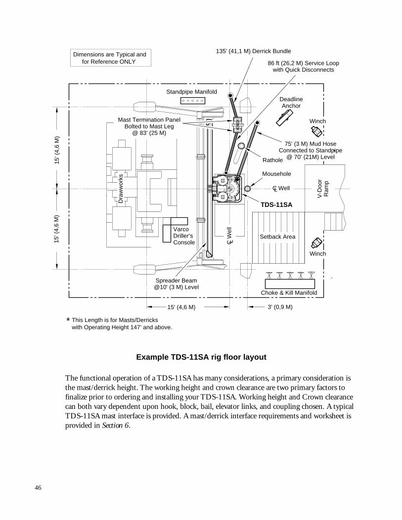
All of the above modifications may not be necessary, but all must be considered as well as theoverall rig floor layout in order to ensure that proper installation, time utilization and accuratecost information is made. One of many possible rig floor layouts is depicted below (referenceonly).
46
Rathole
Setback AreaVarcoDriller’sConsole
Mousehole
V-D
oor
Ram
p
TDS-11SA
DeadlineAnchor
Standpipe Manifold
Choke & Kill Manifold
Spreader Beam@10' (3 M) Level
86 ft (26,2 M) Service Loopwith Quick Disconnects
75' (3 M) Mud HoseConnected to Standpipe
@ 70' (21M) Level
Mast Termination PanelBolted to Mast Leg
@ 83' (25 M)
3' (0,9 M)
15' (
4,6
M)
15' (
4,6
M)
C W
ell
C Well
135' (41,1 M) Derrick Bundle
*
15' (4,6 M)
L
L
Dra
ww
orks
* This Length is for Masts/Derrickswith Operating Height 147' and above.
Dimensions are Typical andfor Reference ONLY
Winch
Winch
Example TDS-11SA rig floor layout
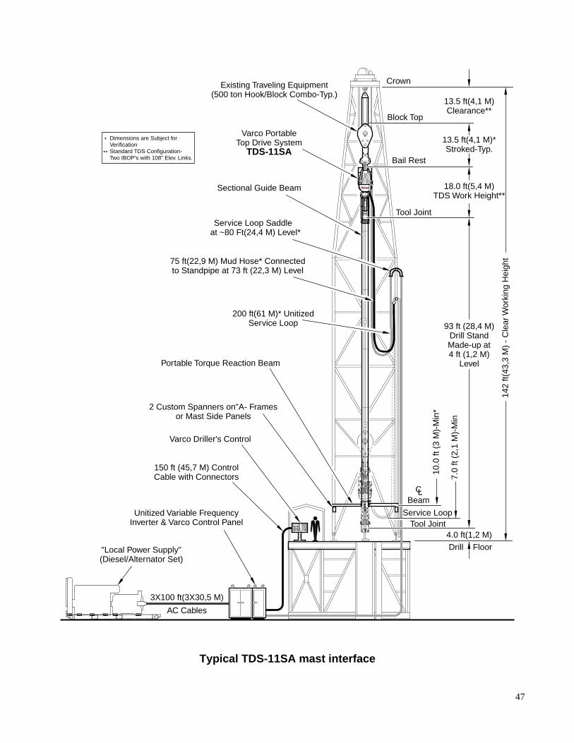
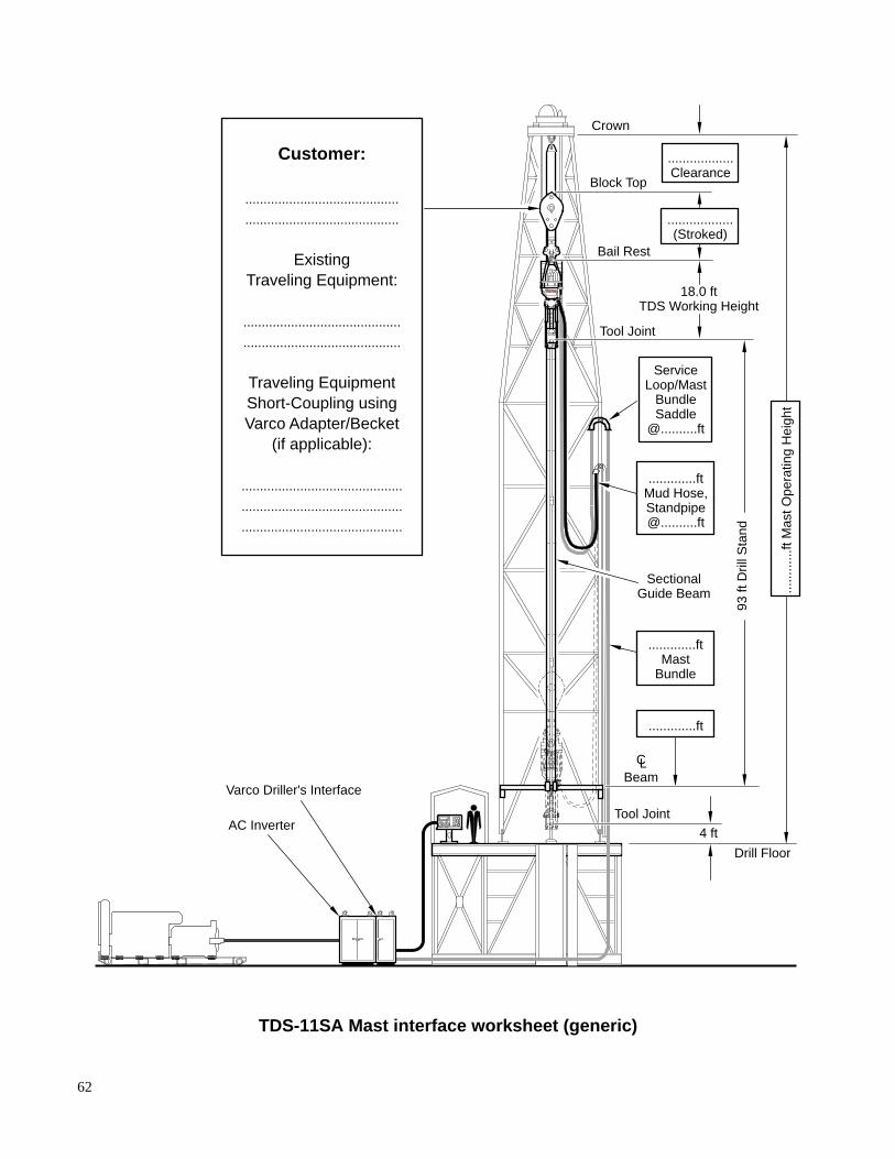
The functional operation of a TDS-11SA has many considerations, a primary consideration isthe mast/derrick height. The working height and crown clearance are two primary factors tofinalize prior to ordering and installing your TDS-11SA. Working height and Crown clearancecan both vary dependent upon hook, block, bail, elevator links, and coupling chosen. A typicalTDS-11SA mast interface is provided. A mast/derrick interface requirements and worksheet isprovided in Section 6.
47
3X100 ft(3X30,5 M)
AC Cables
Existing Traveling Equipment(500 ton Hook/Block Combo-Typ.)
Varco PortableTop Drive System
TDS-11SA
Crown
Block Top
Bail Rest
Tool Joint
Tool Joint
Beam
Service Loop
CL
Sectional Guide Beam
75 ft(22,9 M) Mud Hose* Connectedto Standpipe at 73 ft (22,3 M) Level
200 ft(61 M)* UnitizedService Loop
Service Loop Saddle at ~80 Ft(24,4 M) Level*
Portable Torque Reaction Beam
2 Custom Spanners on"A- Framesor Mast Side Panels
Varco Driller's Control
150 ft (45,7 M) ControlCable with Connectors
"Local Power Supply"(Diesel/Alternator Set)
Unitized Variable FrequencyInverter & Varco Control Panel
Drill Floor
93 ft (28,4 M)Drill StandMade-up at4 ft (1,2 M)
Level
13.5 ft(4,1 M)Clearance**
18.0 ft(5,4 M)TDS Work Height**
13.5 ft(4,1 M)*Stroked-Typ.
4.0 ft(1,2 M)
10.0
ft (
3 M
)-M
in*
7.0
ft (2
,1 M
)-M
in
142
ft(43
,3 M
) -
Cle
ar W
orki
ng H
eigh
t
*
**
Dimensions are Subject forVerificationStandard TDS Configuration-Two IBOP's with 108" Elev. Links.
Typical TDS-11SA mast interface
48
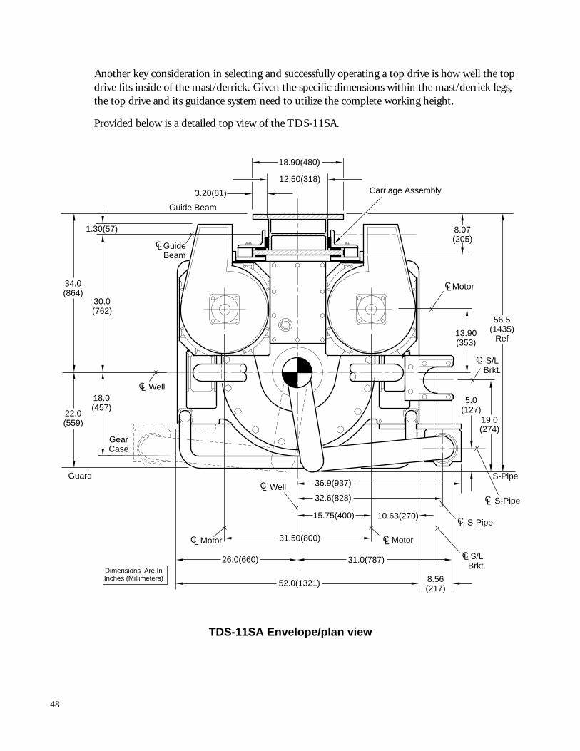
Another key consideration in selecting and successfully operating a top drive is how well the topdrive fits inside of the mast/derrick. Given the specific dimensions within the mast/derrick legs,the top drive and its guidance system need to utilize the complete working height.
Provided below is a detailed top view of the TDS-11SA.
CL Well
52.0(1321)
31.50(800)
15.75(400)
32.6(828)
36.9(937)
10.63(270)
1.30(57)
30.0(762)
34.0(864)
22.0(559)
Guide Beam
18.90(480)
12.50(318)
3.20(81)
MotorCL
8.07(205)
13.90(353)
56.5(1435)
Ref
S-Pipe
GearCase
18.0(457)
MotorCL
Guard
GuideBeam
CL
L WellC
19.0(274)
5.0(127)
8.56(217)
31.0(787)26.0(660)
S/LBrkt.
CL
S/LBrkt.
Dimensions Are InInches (Millimeters)
MotorCL
CL S-Pipe
CL S-Pipe
Carriage Assembly
CL
TDS-11SA Envelope/plan view
49
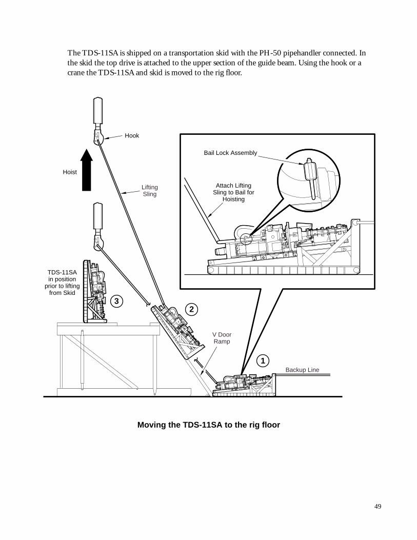
The TDS-11SA is shipped on a transportation skid with the PH-50 pipehandler connected. Inthe skid the top drive is attached to the upper section of the guide beam. Using the hook or acrane the TDS-11SA and skid is moved to the rig floor.
V DoorRamp
LiftingSling
Backup Line
Hook
Hoist
TDS-11SAin position
prior to liftingfrom Skid
2
Bail Lock Assembly
Attach LiftingSling to Bail for
Hoisting
3
1
Moving the TDS-11SA to the rig floor
50
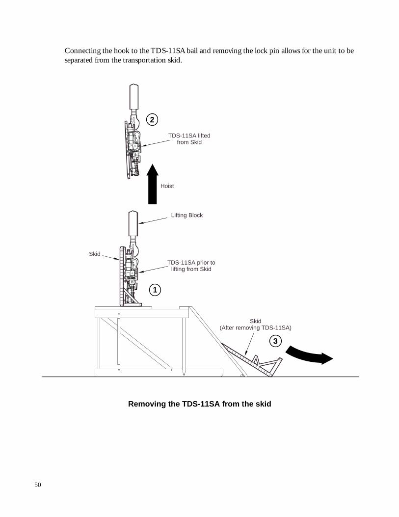
Connecting the hook to the TDS-11SA bail and removing the lock pin allows for the unit to beseparated from the transportation skid.
Skid(After removing TDS-11SA)
TDS-11SA liftedfrom Skid
Lifting Block
Skid
Hoist
TDS-11SA prior tolifting from Skid
2
3
1
Removing the TDS-11SA from the skid
51
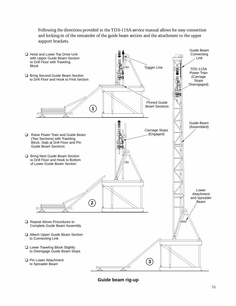
Following the directions provided in the TDS-11SA service manual allows for easy connectionand locking-in of the remainder of the guide beam section and the attachment to the uppersupport brackets.
Guide BeamConnecting
Link
TDS-11SAPower Train(Carriage
StopsDisengaged)
Guide Beam(Assembled)
LowerAttachment
and SpreaderBeam
Carriage Stops(Engaged)
❏ Hoist and Lower Top Drive Unitwith Upper Guide Beam Sectionto Drill Floor with TravelingBlock
❏ Bring Second Guide Beam Sectionto Drill Floor and Hook to First Section
Tugger Line
Pinned GuideBeam Sections
❏ Repeat Above Procedures toComplete Guide Beam Assembly
❏ Attach Upper Guide Beam Sectionto Connecting Link
❏ Lower Traveling Block Slightlyto Disengage Guide Beam Stops
❏ Pin Lower Attachmentto Spreader Beam
❏ Raise Power Train and Guide Beam(Two Sections) with TravelingBlock, Stab at Drill Floor and PinGuide Beam Sections
❏ Bring Next Guide Beam Sectionto Drill Floor and Hook to Bottomof Lower Guide Beam Section
2
3
1
Guide beam rig-up
52
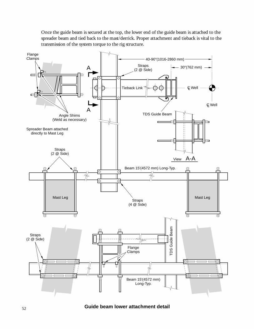
Once the guide beam is secured at the top, the lower end of the guide beam is attached to thespreader beam and tied back to the mast/derrick. Proper attachment and tieback is vital to thetransmission of the system torque to the rig structure.
Mast Leg Mast Leg
A
A
View
Spreader Beam attacheddirectly to Mast Leg
40-90"(1016-2860 mm)
Beam 15'(4572 mm) Long-Typ.
Beam 15'(4572 mm)Long-Typ.
30"(762 mm)
TDS Guide Beam
TD
S G
uide
Bea
m
C WellL
C WellL
Angle Shims(Weld as necessary)
FlangeClamps
FlangeClamps
Straps(2 @ Side)
Straps(2 @ Side)
Straps(2 @ Side)
Straps(4 @ Side)
A-A
Tieback Link
Guide beam lower attachment detail
53
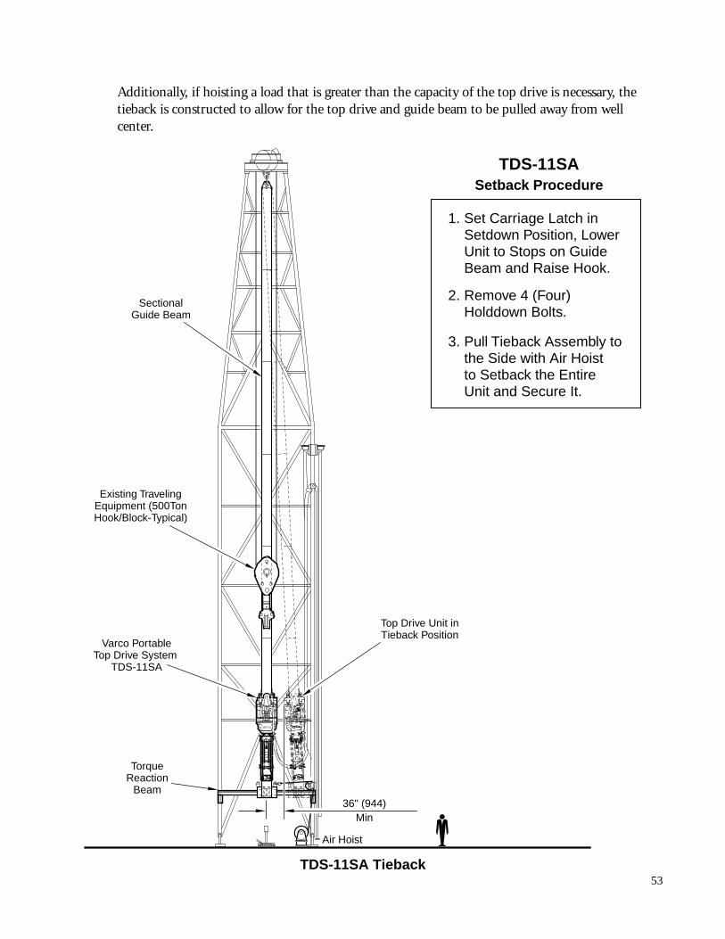
Additionally, if hoisting a load that is greater than the capacity of the top drive is necessary, thetieback is constructed to allow for the top drive and guide beam to be pulled away from wellcenter.
TDS-11SASetback Procedure
Existing TravelingEquipment (500TonHook/Block-Typical)
Varco PortableTop Drive System
TDS-11SA
SectionalGuide Beam
36" (944)Min
TorqueReaction
Beam
Air Hoist
Top Drive Unit inTieback Position
Set Carriage Latch inSetdown Position, LowerUnit to Stops on GuideBeam and Raise Hook.
Remove 4 (Four)Holddown Bolts.
Pull Tieback Assembly tothe Side with Air Hoistto Setback the EntireUnit and Secure It.
1.
2.
3.
TDS-11SA Tieback
54
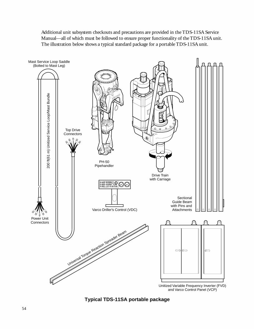
Additional unit subsystem checkouts and precautions are provided in the TDS-11SA ServiceManual—all of which must be followed to ensure proper functionality of the TDS-11SA unit.The illustration below shows a typical standard package for a portable TDS-11SA unit.
Unitized Variable Frequency Inverter (FVD)and Varco Control Panel (VCP)
Varco Driller’s Control (VDC)
Drive Trainwith Carriage
SectionalGuide Beam
with Pins andAttachments
PH-50Pipehandler20
0 ft(
61 m
) U
nitiz
ed S
ervi
ce L
oop/
Mas
t Bun
dle
Power UnitConnectors
Mast Service Loop Saddle(Bolted to Mast Leg)
Top DriveConnectors
Universal Torque Reaction Spreader B
eam
Typical TDS-11SA portable package
55
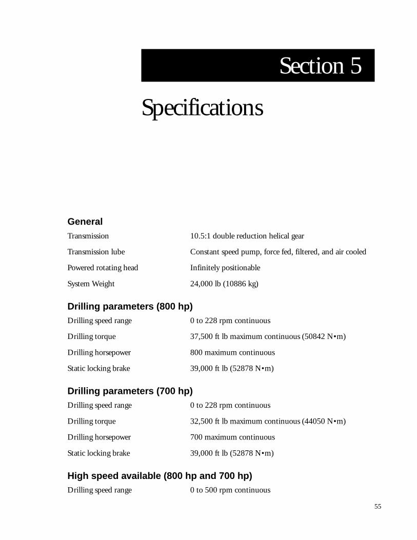
Section 5
Specifications
GeneralTransmission 10.5:1 double reduction helical gear
Transmission lube Constant speed pump, force fed, filtered, and air cooled
Powered rotating head Infinitely positionable
System Weight 24,000 lb (10886 kg)
Drilling parameters (800 hp)Drilling speed range 0 to 228 rpm continuous
Drilling torque 37,500 ft lb maximum continuous (50842 N•m)
Drilling horsepower 800 maximum continuous
Static locking brake 39,000 ft lb (52878 N•m)
Drilling parameters (700 hp)Drilling speed range 0 to 228 rpm continuous
Drilling torque 32,500 ft lb maximum continuous (44050 N•m)
Drilling horsepower 700 maximum continuous
Static locking brake 39,000 ft lb (52878 N•m)
High speed available (800 hp and 700 hp)Drilling speed range 0 to 500 rpm continuous
56
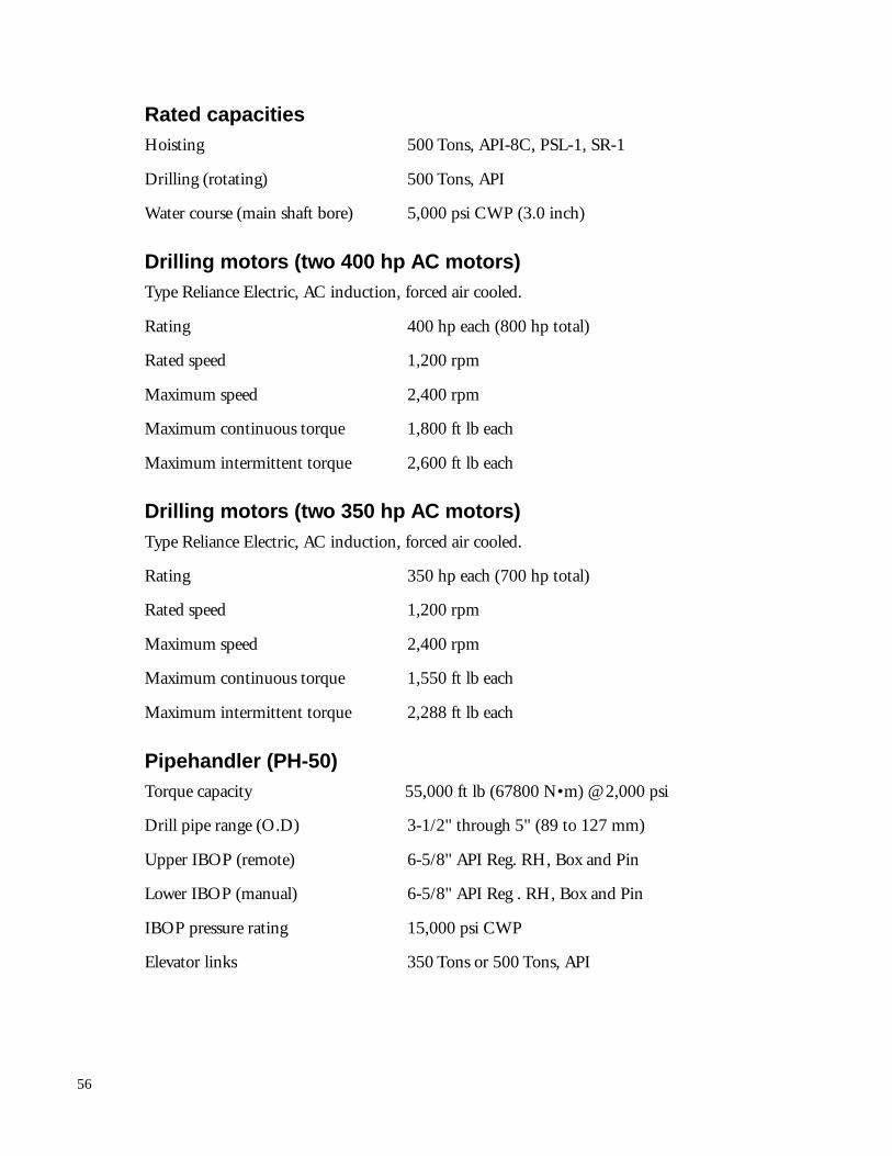
Rated capacitiesHoisting 500 Tons, API-8C, PSL-1, SR-1
Drilling (rotating) 500 Tons, API
Water course (main shaft bore) 5,000 psi CWP (3.0 inch)
Drilling motors (two 400 hp AC motors)Type Reliance Electric, AC induction, forced air cooled.
Rating 400 hp each (800 hp total)
Rated speed 1,200 rpm
Maximum speed 2,400 rpm
Maximum continuous torque 1,800 ft lb each
Maximum intermittent torque 2,600 ft lb each
Drilling motors (two 350 hp AC motors)Type Reliance Electric, AC induction, forced air cooled.
Rating 350 hp each (700 hp total)
Rated speed 1,200 rpm
Maximum speed 2,400 rpm
Maximum continuous torque 1,550 ft lb each
Maximum intermittent torque 2,288 ft lb each
Pipehandler (PH-50)Torque capacity 55,000 ft lb (67800 N•m) @ 2,000 psi
Drill pipe range (O.D) 3-1/2" through 5" (89 to 127 mm)
Upper IBOP (remote) 6-5/8" API Reg. RH, Box and Pin
Lower IBOP (manual) 6-5/8" API Reg . RH, Box and Pin
IBOP pressure rating 15,000 psi CWP
Elevator links 350 Tons or 500 Tons, API

57
Section 6
Appendix
58
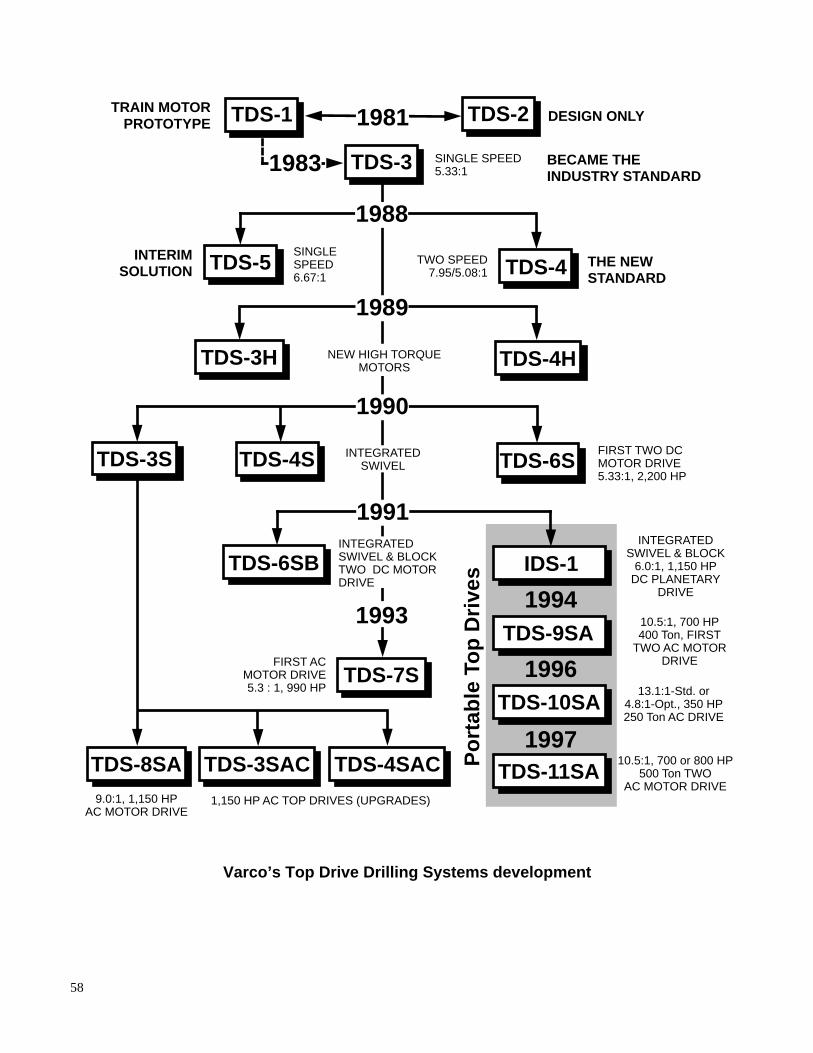
TRAIN MOTORPROTOTYPE DESIGN ONLY
BECAME THEINDUSTRY STANDARD
INTERIMSOLUTION TDS-5
TDS-4HTDS-3H
TDS-3S TDS-6STDS-4S
SINGLE SPEED5.33:1
SINGLESPEED6.67:1
TWO SPEED7.95/5.08:1
THE NEWSTANDARD
1983
FIRST TWO DCMOTOR DRIVE5.33:1, 2,200 HP
TDS-6SBINTEGRATED
SWIVEL & BLOCK6.0:1, 1,150 HP
DC PLANETARYDRIVE
Po
rtab
le T
op
Dri
ves
FIRST ACMOTOR DRIVE5.3 : 1, 990 HP
9.0:1, 1,150 HPAC MOTOR DRIVE
1,150 HP AC TOP DRIVES (UPGRADES)
INTEGRATEDSWIVEL & BLOCKTWO DC MOTORDRIVE
NEW HIGH TORQUEMOTORS
1988
1989
1990
TDS-2
TDS-3
TDS-7S
TDS-3SAC TDS-4SACTDS-8SA
1994
INTEGRATEDSWIVEL
10.5:1, 700 HP400 Ton, FIRST
TWO AC MOTORDRIVE
TDS-1 1981
1996
1997
TDS-10SA
IDS-1
TDS-9SA
TDS-11SA
13.1:1-Std. or4.8:1-Opt., 350 HP250 Ton AC DRIVE
10.5:1, 700 or 800 HP500 Ton TWO
AC MOTOR DRIVE
1993
1991
TDS-4
Varco’s Top Drive Drilling Systems development
59
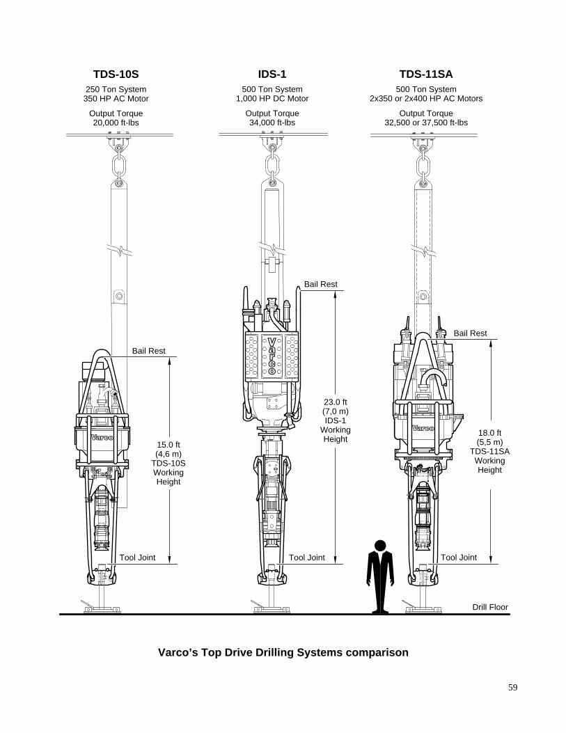
Bail Rest
IDS-1500 Ton System
1,000 HP DC Motor
Output Torque34,000 ft-lbs
TDS-11SA500 Ton System
2x350 or 2x400 HP AC Motors
Output Torque32,500 or 37,500 ft-lbs
Bail Rest
Bail Rest
Drill Floor
Tool Joint Tool Joint
23.0 ft(7,0 m)IDS-1
WorkingHeight
18.0 ft(5,5 m)
TDS-11SAWorkingHeight
TDS-10S250 Ton System350 HP AC Motor
Output Torque20,000 ft-lbs
Tool Joint
15.0 ft(4,6 m)
TDS-10SWorkingHeight
Varco’s Top Drive Drilling Systems comparison
60
25 50 75 100 125
Drill Pipe RPM
Dual AC Motor Top Drive TDS-11SA2 x 350 = 700 HP or 2 x 400 = 800 HP 500 Ton System, 10.5:1 Transmission
150 175 200 225 25000
5,000
10,000
15,000
20,000
25,000
30,000
Dri
ll P
ipe
Torq
ue
(ft-
lbs)
35,000
40,000
45,000
700 HP
800 HP
50,000
55,000
TDS-11SA Output curve
61
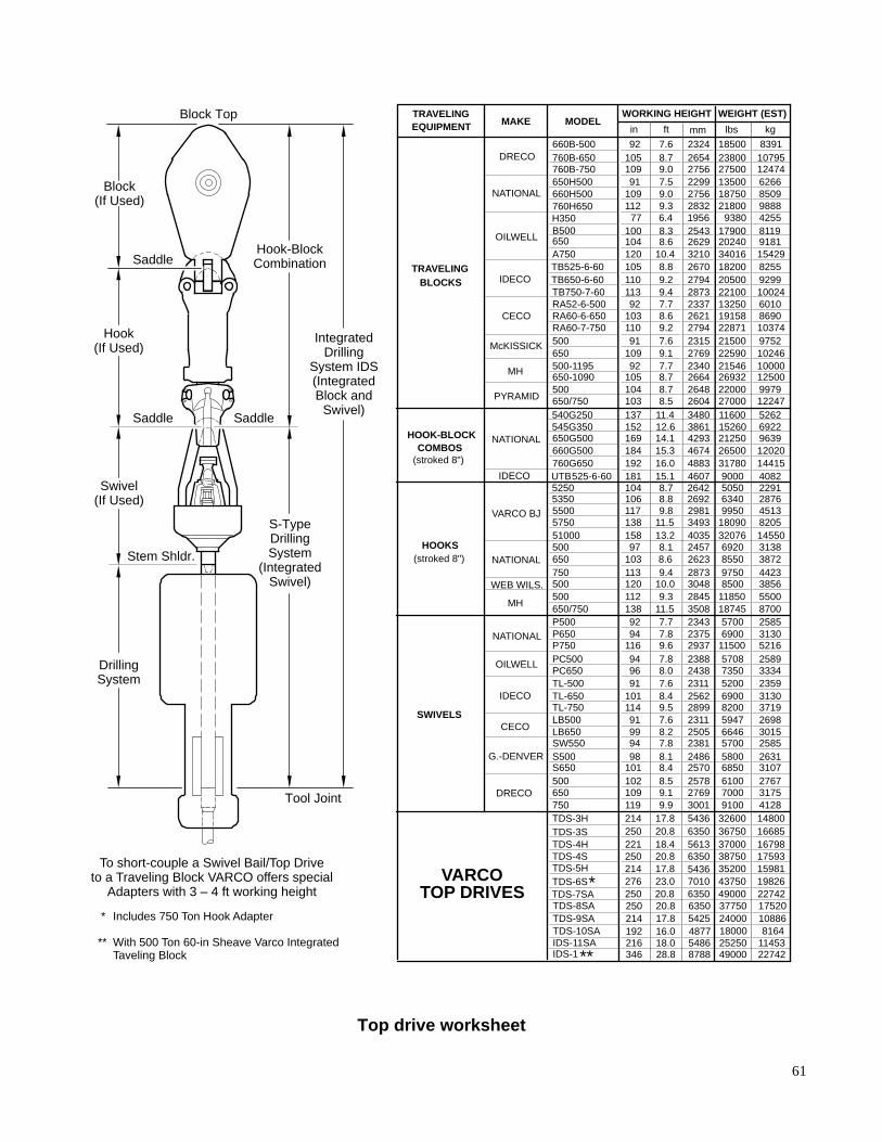
TRAVELINGEQUIPMENT MAKE MODEL
WORKING HEIGHT WEIGHT (EST)
in ft mm lbs kg
660B-500 92 7.6 2324 18500 8391DRECO 760B-650 105 8.7 2654 23800 10795
760B-750 109 9.0 2756 27500 12474650H500 91 7.5 2299 13500 6266
NATIONAL 660H500 109 9.0 2756 18750 8509760H650 112 9.3 2832 21800 9888
B500 100 8.3 2543 17900 8119OILWELL 650 104 8.6 2629 20240 9181
A750 120 10.4 3210 34016 15429
TRAVELING TB525-6-60 105 8.8 2670 18200 8255
BLOCKS IDECO TB650-6-60 110 9.2 2794 20500 9299TB750-7-60 113 9.4 2873 22100 10024RA52-6-500 92 7.7 2337 13250 6010
CECO RA60-6-650 103 8.6 2621 19158 8690RA60-7-750 110 9.2 2794 22871 10374
McKISSICK 500 91 7.6 2315 21500 9752650 109 9.1 2769 22590 10246
MH 500-1195 92 7.7 2340 21546 10000650-1090 105 8.7 2664 26932 12500
PYRAMID500 104 8.7 2648 22000 9979650/750 103 8.5 2604 27000 12247
HOOK-BLOCK 650G500 169 14.1 4293 21250 9639 COMBOS
NATIONAL660G500 184 15.3 4674 26500 12020
(stroked 8") 760G650 192 16.0 4883 31780 14415IDECO UTB 525-6-60 181 15.1 4607 9000 4082
545G350 152 12.6 3861 15260 6922540G250 137 11.4 3480 11600 5262
5500 117 9.8 2981 9950 4513VARCO BJ5750 138 11.5 3493 18090 820551000 158 13.2 4035 32076 14550
HOOKS 500 97 8.1 2457 6920 3138NATIONAL 650 103 8.6 2623 8550 3872
750 113 9.4 2873 9750 4423WEB WILS. 500 120 10.0 3048 8500 3856
MH500 112 9.3 2845 11850 5500650/750 138 11.5 3508 18745 8700P500 92 7.7 2343 5700 2585
NATIONAL P650 94 7.8 2375 6900 3130P750 116 9.6 2937 11500 5216
OILWELL PC500 94 7.8 2388 5708 2589PC650 96 8.0 2438 7350 3334TL-500 91 7.6 2311 5200 2359
IDECO TL-650 101 8.4 2562 6900 3130TL-750 114 9.5 2899 8200 3719
SWIVELSCECO
LB500 91 7.6 2311 5947 2698LB650 99 8.2 2505 6646 3015SW550 94 7.8 2381 5700 2585
G.-DENVER S500 98 8.1 2486 5800 2631S650 101 8.4 2570 6850 3107500 102 8.5 2578 6100 2767
DRECO 650 109 9.1 2769 7000 3175750 119 9.9 3001 9100 4128TDS-3H 214 17.8 5436 32600 14800TDS-3S 250 20.8 6350 36750 16685TDS-4H 221 18.4 5613 37000 16798
VARCOTOP DRIVES
TDS-4S 250 20.8 6350 38750 17593TDS-5H 214 17.8 5436 35200 15981TDS-6S* 276 23.0 7010 43750 19826
IDS-11SA 216 18.0 5486 25250 11453
(stroked 8")
TDS-7SA 250 20.8 6350 49000 22742TDS-8SA 250 20.8 6350 37750 17520TDS-9SA 214 17.8 5425 24000 10886
5350 106 8.8 2692 6340 28765250 104 8.7 2642 5050 2291
TDS-10SA 192 16.0 4877 18000 8164
H350 77 6.4 1956 9380 4255
IDS-1** 346 28.8 8788 49000 22742
Block Top
Block(If Used)
Hook(If Used)
Swivel(If Used)
DrillingSystem
Hook-BlockCombination
S-TypeDrillingSystem
(IntegratedSwivel)
Tool Joint
IntegratedDrilling
System IDS(IntegratedBlock and
Swivel)
Saddle
Saddle
Stem Shldr.
Saddle
To short-couple a Swivel Bail/Top Driveto a Traveling Block VARCO offers special
Adapters with 3 – 4 ft working height
Includes 750 Ton Hook Adapter
With 500 Ton 60-in Sheave Varco IntegratedTaveling Block
*
**
Top drive worksheet
62
Varco Driller's Interface
AC Inverter
Drill Floor
4 ft
Beam
.............ft
.............ftMast
Bundle
.............ftMud Hose,[email protected]
ServiceLoop/Mast
BundleSaddle
@..........ft
..................Clearance
Customer:
..........................................
..........................................
ExistingTraveling Equipment:
...........................................
...........................................
Traveling EquipmentShort-Coupling usingVarco Adapter/Becket
(if applicable):
............................................
............................................
............................................
..................(Stroked)
18.0 ftTDS Working Height
SectionalGuide Beam
Tool Joint
Tool Joint
Bail Rest
Block Top
Crown
CL
......
......
ft M
ast O
pera
ting
Hei
ght
93 ft
Dril
l Sta
nd
TDS-11SA Mast interface worksheet (generic)

63

64