Embed Size (px)
Citation preview
Installation Criteria for Taxiway Centerline Lights
James W. Patterson, Jr. May 2006 DOT/FAA/AR-TN06/6 This document is available to the public through the National Technical Information Service (NTIS), Springfield, Virginia 22161.
U.S. Department of Transportation Federal Aviation Administration
ote
tech
nica
l not
e te
chni
caot
e te
chni
cal n
ote
tech
nica
NOTICE
This document is disseminated under the sponsorship of the U.S. Department of Transportation in the interest of information exchange. The United States Government assumes no liability for the contents or use thereof. The United States Government does not endorse products or manufacturers. Trade or manufacturer's names appear herein solely because they are considered essential to the objective of this report. This document does not constitute FAA certification policy. Consult your local FAA airports office as to its use. This report is available at the Federal Aviation Administration William J. Hughes Technical Center’s Full-Text Technical Reports page: actlibrary.tc.faa.gov in Adobe Acrobat portable document format (PDF).
Technical Report Documentation Page
1. Report No.
DOT/FAA/AR-TN06/6
2. Government Accession No.
3. Recipient's Catalog No.
5. Report Date
May 2006
4. Title and Subtitle
INSTALLATION CRITERIA FOR TAXIWAY CENTERLINE LIGHTS
6. Performing Organization Code
7. Author(s)
James W. Patterson
8. Performing Organization Report No.
ATO-P R&D 10. Work Unit No. (TRAIS)
9. Performing Organization Name and Address
Federal Aviation Administration William J. Hughes Technical Center Airport and Aircraft Safety Research and Development Division Airport Technology Research and Development Branch Atlantic City International Airport, NJ 08405
11. Contract or Grant No.
12. Sponsoring Agency Name and Address
U.S. Department of Transportation Federal Aviation Administration
13. Type of Report and Period Covered
Technical Note
Office of Aviation Research and Development Washington, DC 20591
14. Sponsoring Agency Code
AAS-100 15. Supplementary Notes
Oswaldo Valdivieso, of Hi-Tec Systems Inc., provided technical support throughout the course of this evaluation. 16. Abstract
The Federal Aviation Administration (FAA) Advisory Circular (AC) 150/5340-30, “Design and Installation Details of Airport Visual Aids,” requires that properly installed taxiway centerline fixtures should, when placed on a taxiway curve with radii between 75 and 399 feet, maintain that three lights are visible from the cockpit, provide information to the pilot on how sharp the curve is, provide the pilot with an indication of how far off the taxiway centerline the aircraft might be, and visually look the same from both directions of travel. Typically, the FAA type L-852D taxiway centerline fixture is spaced at 12.5 feet when placed on a taxiway curve with radii between 75 and 399 feet. The International Civil Aviation Organization (ICAO) version of the taxiway centerline fixture, which is designed specifically for curved applications, is spaced at 25 feet when placed on the same taxiway curve. The objective of this research was to determine what would happen if the FAA type L-852D taxiway centerline fixture was placed at a spacing of 25 feet; the same spacing as the ICAO fixture. To perform this evaluation, a series of six FAA type L-852D fixtures and six ICAO fixtures were temporarily installed on the ramp area of the FAA William J. Hughes Technical Center. Each set of lights was positioned such that they represented a taxiway centerline curve with a 75-foot radius, spaced at 25 feet. Taxiing tests were performed over each set of lights to determine if each set met the requirements set forth in AC 150/5340-30. The results showed that the FAA type L-852D taxiway centerline fixtures did not meet the requirements of the AC, because it was not possible to see the minimum three lights from the cockpit. This was attributed to the narrow beam spread of the fixtures, and the fact that the fixtures are not designed specifically for curved applications. The ICAO fixture met all the requirements of AC 150/5340-30.
17. Key Words
Taxiway centerline, ICAO spacing, L-852D, Lighting, Visual guidance
18. Distribution Statement
This document is available to the public through the National Technical Information Service (NTIS), Springfield, Virginia 22161.
19. Security Classif. (of this report)
Unclassified
20. Security Classif. (of this page)
Unclassified
21. No. of Pages
21
22. Price
Form DOT F1700.7 (8-72) Reproduction of completed page authorized
TABLE OF CONTENTS Page EXECUTIVE SUMMARY vii INTRODUCTION 1
Background 1 Scope 2 Objective 2 Requirements 2 Reference Documents 2 System Description 3 Test Configuration 3 Schedule and Participants 4 Test Constraints and Limitations 4
TEST RESULTS 5
The FAA Type L-852D Fixtures Using ICAO Spacing Criteria 5
Objective 5 Results 5
The ICAO Fixture Using ICAO Spacing Criteria 8
Objective 8 Results 9
Comparative Photometric Tests 11
CONCLUDING REMARKS 12
iii
LIST OF FIGURES Figure Page 1 The FAA Type L-852D Fixture 1
2 The ICAO Fixture 1
3 Test Layout 3
4 The FAA Type L-852D Fixture, 25-ft Separation 6
5 The FAA Type L-852D Fixture Beam Coverage on a 75-ft Radius Taxiway Using ICAO and FAA Spacing Standards 7
6 The ICAO Fixture, Photometric Data 9
7 The ICAO Fixture, 25-ft Separation 10
8 The ICAO Fixture Beam Coverage on a 75-ft Radius Taxiway 11
iv

LIST OF TABLES Tables Page 1 Photometric Requirements for In-Pavement Lights 5 2 Evaluation Data Sheet (FAA 75-ft Radius, 25-ft Spacing) 6 3 Evaluation Data Sheet (ICAO 75-ft Radius, 25-ft Spacing) 9 4 Relative Photometric Data 12
v
LIST OF ACRONYMS
AC Advisory Circular FAA Federal Aviation Administration IACO International Civil Aviation Organization RVR Runway visual range
vi
EXECUTIVE SUMMARY Research was conducted to evaluate the suitability of using Federal Aviation Administration (FAA) type L-852D taxiway centerline lights on curved taxiways at a nonstandard spacing distance of 25 ft. Typically, the type L-852D taxiway centerline fixture, when used on taxiways with radii between 75 and 399 ft, is spaced at 12.5 ft. The International Civil Aviation Organization (ICAO) uses a fixture that is designed specifically for curved applications that allows for a longer spacing requirement of 25 ft. New York’s La Guardia Airport, in their Surface Movement Guidance and Control System plan being prepared for minimum authorized operations under 1200-ft runway visual range, proposes the installation of the FAA type L-852D taxiway centerline lights using the 25-ft spacing requirements of ICAO. The objective of this research was to evaluate the required longitudinal spacing for both the FAA type L-852D and ICAO taxiway centerline lights, considering notable differences in design, photometrics, and mounting orientation of the two fixtures. The FAA Advisory Circular (AC) 150/5340-30, “Design and Installation Details of Airport Visual Aids,” provides that taxiway centerline fixtures should, when installed properly, maintain a minimal visual segment of three lights beyond the cockpit cutoff, provide information on the rate of change of direction of the curve, provide indication of the magnitude of any displacement of the aircraft from the taxiway centerline, and operate normally in both directions of travel. The FAA type L-852D taxiway centerline fixture was found to possess a very narrow main beam that, when spaced at 25 ft, did not provide sufficient beamwidth to meet the requirements in FAA AC 150/5340-30. The AC provides guidance for the spacing of the FAA type L-852D fixture for taxiway curves of various radii. The FAA type L-852D fixture’s narrow beam is taken into account, and as a result, the AC defines a separation requirement of 12.5 ft. At the 25-ft spacing, the FAA type L-852D taxiway centerline fixture was unable to maintain the visual segment of three lights beyond the cockpit cutoff. By the FAA’s definition, this disqualifies the FAA type L-852D taxiway centerline from being used at 25-ft spacing. Based on the data and information gathered during this research effort, the FAA type L-852D taxiway centerline fixtures, by design and by performance, do not have the overall beamwidth necessary to be placed at a separation distance other than those cited in FAA AC 150/5340-30. The ICAO fixture did perform satisfactorily when placed at the ICAO spacing of 25 ft.
vii/viii
INTRODUCTION
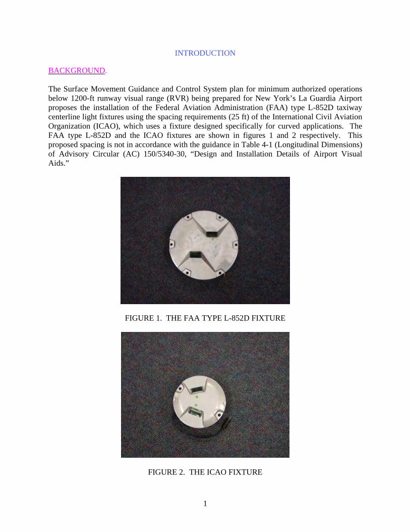
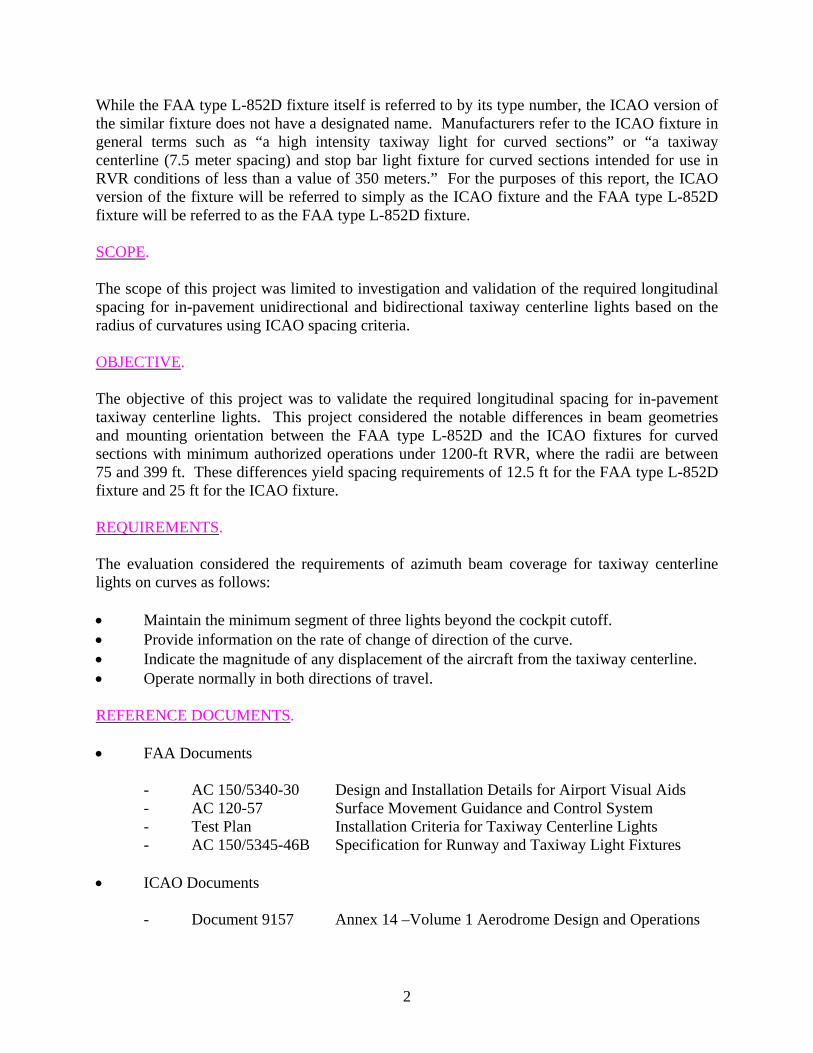
BACKGROUND. The Surface Movement Guidance and Control System plan for minimum authorized operations below 1200-ft runway visual range (RVR) being prepared for New York’s La Guardia Airport proposes the installation of the Federal Aviation Administration (FAA) type L-852D taxiway centerline light fixtures using the spacing requirements (25 ft) of the International Civil Aviation Organization (ICAO), which uses a fixture designed specifically for curved applications. The FAA type L-852D and the ICAO fixtures are shown in figures 1 and 2 respectively. This proposed spacing is not in accordance with the guidance in Table 4-1 (Longitudinal Dimensions) of Advisory Circular (AC) 150/5340-30, “Design and Installation Details of Airport Visual Aids.”
FIGURE 1. THE FAA TYPE L-852D FIXTURE
FIGURE 2. THE ICAO FIXTURE
1
While the FAA type L-852D fixture itself is referred to by its type number, the ICAO version of the similar fixture does not have a designated name. Manufacturers refer to the ICAO fixture in general terms such as “a high intensity taxiway light for curved sections” or “a taxiway centerline (7.5 meter spacing) and stop bar light fixture for curved sections intended for use in RVR conditions of less than a value of 350 meters.” For the purposes of this report, the ICAO version of the fixture will be referred to simply as the ICAO fixture and the FAA type L-852D fixture will be referred to as the FAA type L-852D fixture. SCOPE. The scope of this project was limited to investigation and validation of the required longitudinal spacing for in-pavement unidirectional and bidirectional taxiway centerline lights based on the radius of curvatures using ICAO spacing criteria. OBJECTIVE. The objective of this project was to validate the required longitudinal spacing for in-pavement taxiway centerline lights. This project considered the notable differences in beam geometries and mounting orientation between the FAA type L-852D and the ICAO fixtures for curved sections with minimum authorized operations under 1200-ft RVR, where the radii are between 75 and 399 ft. These differences yield spacing requirements of 12.5 ft for the FAA type L-852D fixture and 25 ft for the ICAO fixture. REQUIREMENTS. The evaluation considered the requirements of azimuth beam coverage for taxiway centerline lights on curves as follows: • Maintain the minimum segment of three lights beyond the cockpit cutoff. • Provide information on the rate of change of direction of the curve. • Indicate the magnitude of any displacement of the aircraft from the taxiway centerline. • Operate normally in both directions of travel. REFERENCE DOCUMENTS. • FAA Documents
- AC 150/5340-30 Design and Installation Details for Airport Visual Aids - AC 120-57 Surface Movement Guidance and Control System - Test Plan Installation Criteria for Taxiway Centerline Lights - AC 150/5345-46B Specification for Runway and Taxiway Light Fixtures
• ICAO Documents
- Document 9157 Annex 14 –Volume 1 Aerodrome Design and Operations
2
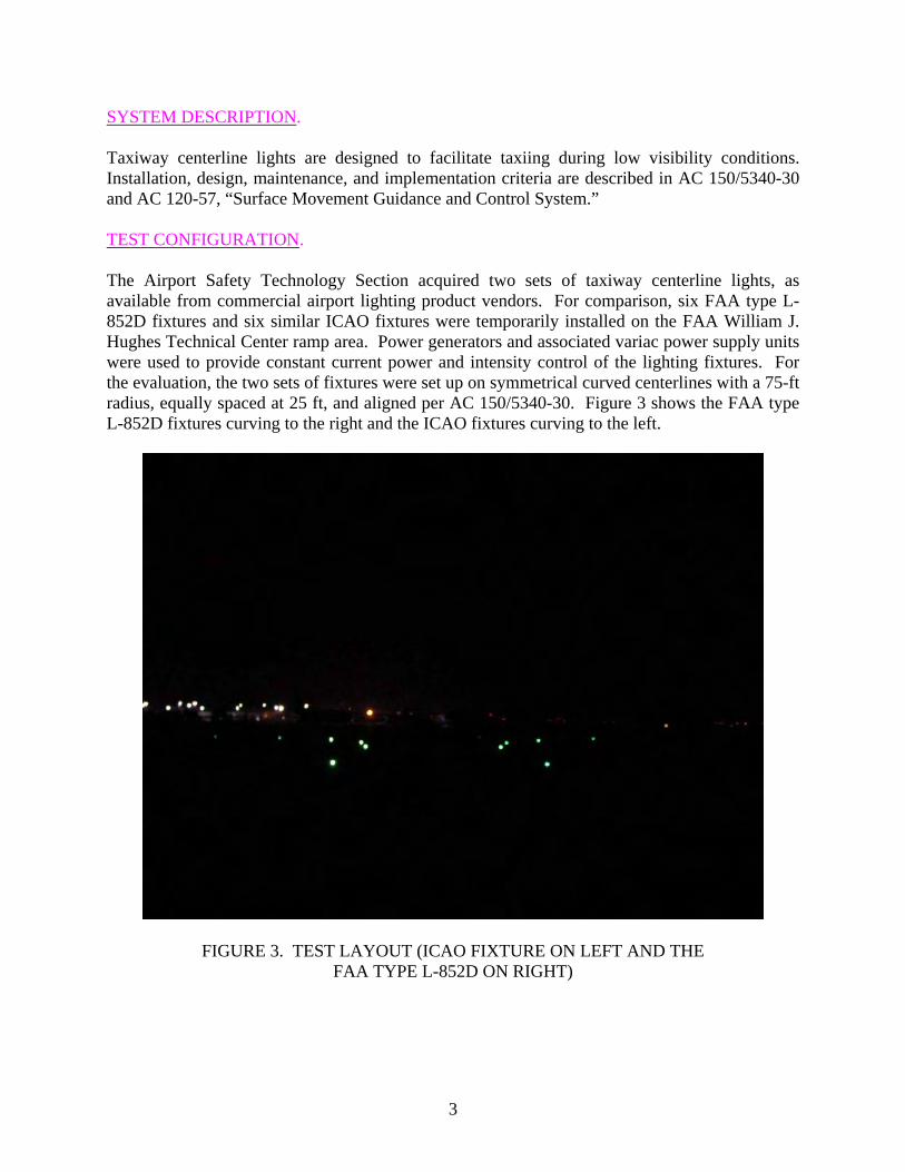
SYSTEM DESCRIPTION. Taxiway centerline lights are designed to facilitate taxiing during low visibility conditions. Installation, design, maintenance, and implementation criteria are described in AC 150/5340-30 and AC 120-57, “Surface Movement Guidance and Control System.” TEST CONFIGURATION. The Airport Safety Technology Section acquired two sets of taxiway centerline lights, as available from commercial airport lighting product vendors. For comparison, six FAA type L-852D fixtures and six similar ICAO fixtures were temporarily installed on the FAA William J. Hughes Technical Center ramp area. Power generators and associated variac power supply units were used to provide constant current power and intensity control of the lighting fixtures. For the evaluation, the two sets of fixtures were set up on symmetrical curved centerlines with a 75-ft radius, equally spaced at 25 ft, and aligned per AC 150/5340-30. Figure 3 shows the FAA type L-852D fixtures curving to the right and the ICAO fixtures curving to the left.
FIGURE 3. TEST LAYOUT (ICAO FIXTURE ON LEFT AND THE FAA TYPE L-852D ON RIGHT)
3
SCHEDULE AND PARTICIPANTS.
On the night of September 16, 2004, the installation criteria for the taxiway centerline light tests and a pretest briefing was conducted at the FAA William J. Hughes Technical Center in Atlantic City, New Jersey. Photometric laboratory testing of both the FAA type L-852D and ICAO fixtures was conducted from September 20 to September 24, 2004. The following organizations and personnel participated in the testing for the installation criteria for taxiway centerline lights:
Participant Organization/Role Alvin Logan AAS-100/Project Officer Tom Mai AAS-100/FAA Engineer Jim Patterson ATO-P R&D/Project Manager/Pilot Don Gallagher ATO-P R&D/FAA Engineer Holly Cyrus ATO-P R&D/FAA Engineer Oswaldo Valdivieso Hi-Tec Systems/Project Lead Tom Paprocki Hi-Tec Systems/Engineer/Pilot Renee Frierson Hi-Tec Systems/Engineer/Pilot Jim Newman Hi-Tec Systems/Project Technician
TEST CONSTRAINTS AND LIMITATIONS. There were several limitations and constraints applicable to the installation criteria taxiway centerline light tests. These limitations and constraints were discussed during pretest briefing and during the performance of the tests. The following list of limitations and constraints were discussed: • RVR conditions under 1200 ft were not simulated. The William J. Hughes Technical
Center does not yet have the capabilities to simulate RVR conditions. • Though suggested, Allard’s Law was not used to test the requirements. Instead, best
RVR conditions available at the time were used in conjunction with geometry and installation criteria, as stated in the installation criteria taxiway centerline light Test Plan.
• The air stairs-equipped vehicle, typically used for viewing airfield lighting devices, was
not available for the tests. • During the performance of the different test scenarios, it was decided by the test team and
the FAA project officer that the scenarios involving the maximum radius of 399 ft for RVR under 1200 ft were unnecessary, because it was determined that this would be a best-case scenario, which would be dismissed once the tighter radii turns were evaluated. Likewise, the scenario involving the FAA AC criteria for spacing of taxiway centerline lights at 12.5 ft was not tested, because the FAA spacing criteria at 12.5 ft was evaluated earlier that same night for a different project.
4
TEST RESULTS
THE FAA TYPE L-852D FIXTURES USING ICAO SPACING CRITERIA. OBJECTIVE. This test scenario evaluated the proposed spacing criteria for taxiway centerline lights using ICAO’s standard of 25-ft spacing for taxiways with a 75-ft radius for RVR under 1200-ft operations. This scenario evaluated the following criteria: • Maintain the minimum segment of three lights beyond the cockpit cutoff • Provide information on the rate of change of direction of the curve • Indicate the magnitude of any displacement of the aircraft from the taxiway centerline • Operate normally in both directions of travel RESULTS. The FAA type L-852D fixture obtained from Siemens Airfield Solutions met and surpassed the minimum photometric requirements set forth in AC 150/5345-46B as shown in table 1.
TABLE 1. PHOTOMETRIC REQUIREMENTS FOR IN-PAVEMENT LIGHTS
Minimum Beam Coverage (degrees) Main Beam 10 percent
Intensity (Candela)
Type Horizontal Vertical Horizontal Vertical Yellow Green FAA L-852D fixture
±30 1 to 10 ±30 0 to 15 100 100
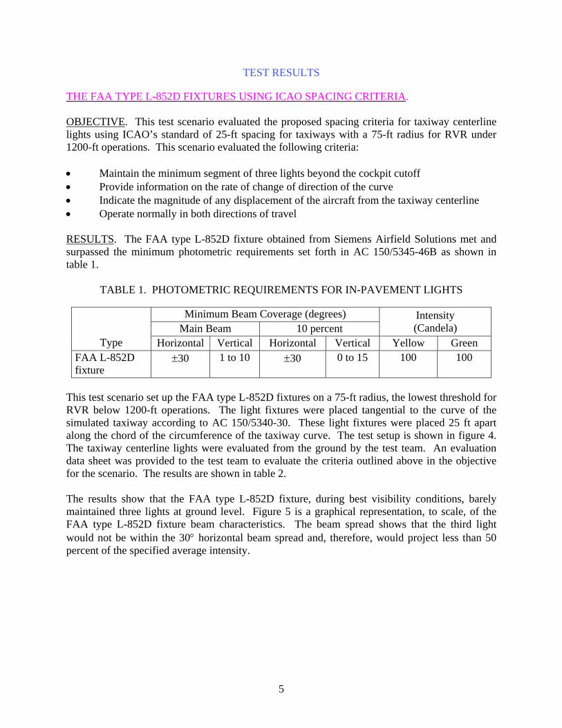
This test scenario set up the FAA type L-852D fixtures on a 75-ft radius, the lowest threshold for RVR below 1200-ft operations. The light fixtures were placed tangential to the curve of the simulated taxiway according to AC 150/5340-30. These light fixtures were placed 25 ft apart along the chord of the circumference of the taxiway curve. The test setup is shown in figure 4. The taxiway centerline lights were evaluated from the ground by the test team. An evaluation data sheet was provided to the test team to evaluate the criteria outlined above in the objective for the scenario. The results are shown in table 2. The results show that the FAA type L-852D fixture, during best visibility conditions, barely maintained three lights at ground level. Figure 5 is a graphical representation, to scale, of the FAA type L-852D fixture beam characteristics. The beam spread shows that the third light would not be within the 30° horizontal beam spread and, therefore, would project less than 50 percent of the specified average intensity.
5
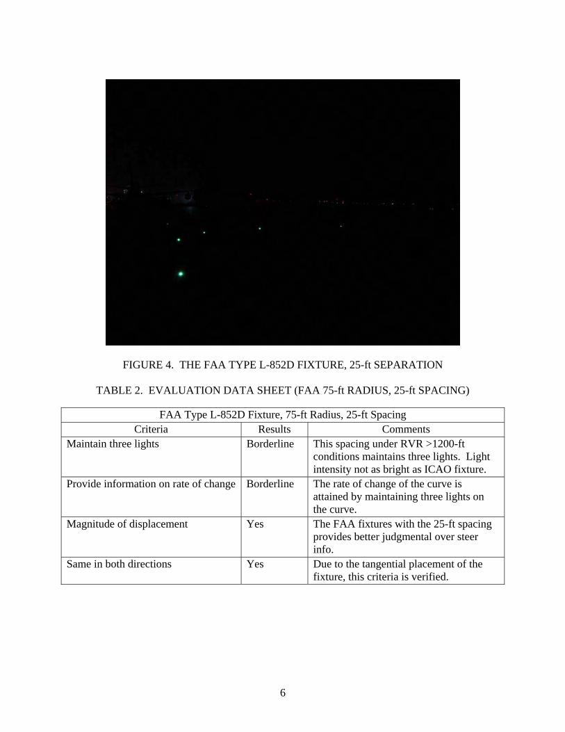
FIGURE 4. THE FAA TYPE L-852D FIXTURE, 25-ft SEPARATION
TABLE 2. EVALUATION DATA SHEET (FAA 75-ft RADIUS, 25-ft SPACING)
FAA Type L-852D Fixture, 75-ft Radius, 25-ft Spacing Criteria Results Comments
Maintain three lights Borderline This spacing under RVR >1200-ft conditions maintains three lights. Light intensity not as bright as ICAO fixture.
Provide information on rate of change Borderline The rate of change of the curve is attained by maintaining three lights on the curve.
Magnitude of displacement Yes The FAA fixtures with the 25-ft spacing provides better judgmental over steer info.
Same in both directions Yes Due to the tangential placement of the fixture, this criteria is verified.
6
.
FIGURE 5. THE FAA TYPE L-852D FIXTURE BEAM COVERAGE ON A 75-ft RADIUS TAXIWAY USING ICAO AND FAA SPACING STANDARDS
Using simple trigonometry, with the known values of the distance to the third light fixture (75 ft) and the minimum specified vertical beam coverage for the FAA type L-852D fixture (10 degrees), one can calculate the maximum height of a cockpit that would maintain a minimum segment of three lights beyond the cockpit cutoff. The calculation is as follows:
⎟⎠⎞
⎜⎝⎛=⇒=
BbAa
Bb
Aa
sinsin
sinsin
where
a = the maximum height of the cockpit angle A = 10 degrees (minimum vertical beam coverage) b = the distance to the third light B = (90-A) = 80 degrees
7
ft2.139848.0751734.0
80sin7510sin
sinsin
=⎟⎠⎞
⎜⎝⎛=
⎟⎠⎞
⎜⎝⎛⇒⎟
⎠⎞
⎜⎝⎛=
a
BbAa
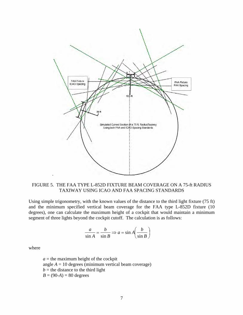
As the calculations above suggest, the maximum cockpit height within which the cockpit would be inside the beam of the fixture is 13.2 ft. With this in consideration, this height would conceivably allow a typical commercial airliner to see three lights beyond the cockpit cutoff distance of 37 ft (for a B737). The three lights that are visible assume ideal RVR conditions, and at that, were considered borderline in this evaluation. Using the FAA standard spacing, a total of six lights would be seen on the same 75-ft stretch beyond the cockpit cutoff.
Figure 5 shows a graphical representation, to scale, of the beam coverage of an FAA type L-852D fixture using both ICAO and FAA spacing standards. The green lines provide a representation of the beam spread, extending for 100 ft in this graphical diagram. The difference of the two beam spreads, ICAO and FAA spacing, clearly show the coverage of each light fixture type.
As described in table 2, three lights are needed to provide enough information to determine the rate of change and direction of the curve. Figure 5 shows that the beam coverage of the FAA type L-852D fixture at ICAO spacing would only be comprised of two light fixtures and, therefore, would be inadequate to determine the rate of change or the direction of the curve. The FAA type L-852D fixture, at ICAO spacing of 25 ft, provides borderline information on the rate of change and direction of the curve.
The tangential placement of the FAA type L-852D fixtures allows for an aircraft to use a judgmental oversteering taxiing technique, which is taxiing with a slightly wider radius than the taxiway centerline. This approach would displace the aircraft beyond the taxiway centerline and in line with more of the fixtures.
Finally, similarly to the above, the tangential placement of the bidirectional FAA type L-852D fixtures fulfills the requirement that operations can be performed normally in both directions of travel, since the light presentation would be identical in both directions.
THE ICAO FIXTURE USING ICAO SPACING CRITERIA.
OBJECTIVE. This test scenario evaluated the ICAO spacing criteria for taxiway centerline lights using 25-ft spacing standard for taxiways with a 75-ft radius for RVR under 1200-ft operations. The scenario used ICAO’s version of the centerline lights. This scenario evaluated the following criteria:
• Maintain the minimum segment of three lights beyond the cockpit cutoff. • Provide information on the rate of change of direction of the curve. • Indicate the magnitude of any displacement of the aircraft from the taxiway centerline. • Operate normally in both directions of travel.
8
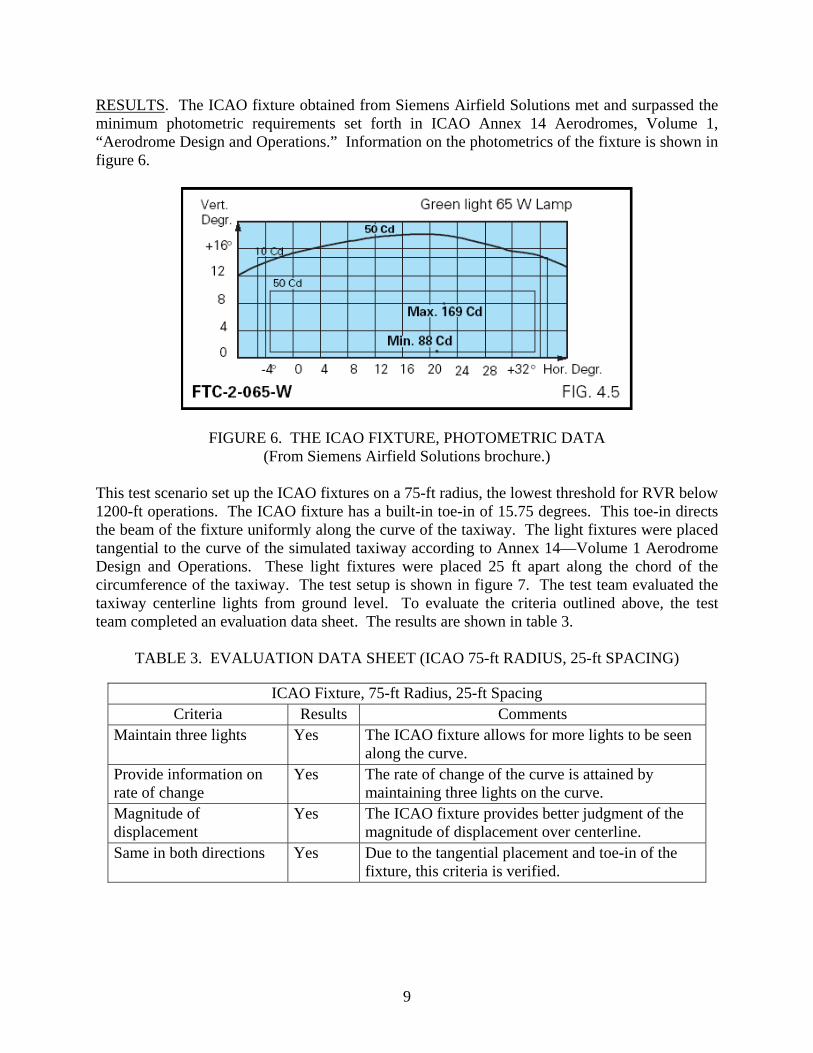
RESULTS. The ICAO fixture obtained from Siemens Airfield Solutions met and surpassed the minimum photometric requirements set forth in ICAO Annex 14 Aerodromes, Volume 1, “Aerodrome Design and Operations.” Information on the photometrics of the fixture is shown in figure 6.
FIGURE 6. THE ICAO FIXTURE, PHOTOMETRIC DATA (From Siemens Airfield Solutions brochure.)
This test scenario set up the ICAO fixtures on a 75-ft radius, the lowest threshold for RVR below 1200-ft operations. The ICAO fixture has a built-in toe-in of 15.75 degrees. This toe-in directs the beam of the fixture uniformly along the curve of the taxiway. The light fixtures were placed tangential to the curve of the simulated taxiway according to Annex 14—Volume 1 Aerodrome Design and Operations. These light fixtures were placed 25 ft apart along the chord of the circumference of the taxiway. The test setup is shown in figure 7. The test team evaluated the taxiway centerline lights from ground level. To evaluate the criteria outlined above, the test team completed an evaluation data sheet. The results are shown in table 3.
TABLE 3. EVALUATION DATA SHEET (ICAO 75-ft RADIUS, 25-ft SPACING)
ICAO Fixture, 75-ft Radius, 25-ft Spacing Criteria Results Comments
Maintain three lights Yes The ICAO fixture allows for more lights to be seen along the curve.
Provide information on rate of change
Yes The rate of change of the curve is attained by maintaining three lights on the curve.
Magnitude of displacement
Yes The ICAO fixture provides better judgment of the magnitude of displacement over centerline.
Same in both directions Yes Due to the tangential placement and toe-in of the fixture, this criteria is verified.
9
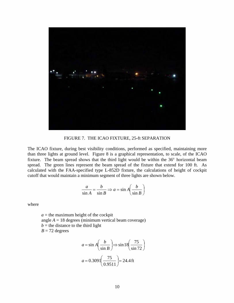
FIGURE 7. THE ICAO FIXTURE, 25-ft SEPARATION The ICAO fixture, during best visibility conditions, performed as specified, maintaining more than three lights at ground level. Figure 8 is a graphical representation, to scale, of the ICAO fixture. The beam spread shows that the third light would be within the 36° horizontal beam spread. The green lines represent the beam spread of the fixture that extend for 100 ft. As calculated with the FAA-specified type L-852D fixture, the calculations of height of cockpit cutoff that would maintain a minimum segment of three lights are shown below.
⎟⎠⎞
⎜⎝⎛=⇒=
BbAa
Bb
Aa
sinsin
sinsin
where
a = the maximum height of the cockpit angle A = 18 degrees (minimum vertical beam coverage) b = the distance to the third light B = 72 degrees
ft4.249511.0753091.0
72sin7518sin
sinsin
=⎟⎠⎞
⎜⎝⎛=
⎟⎠⎞
⎜⎝⎛⇒⎟
⎠⎞
⎜⎝⎛=
a
BbAa
10
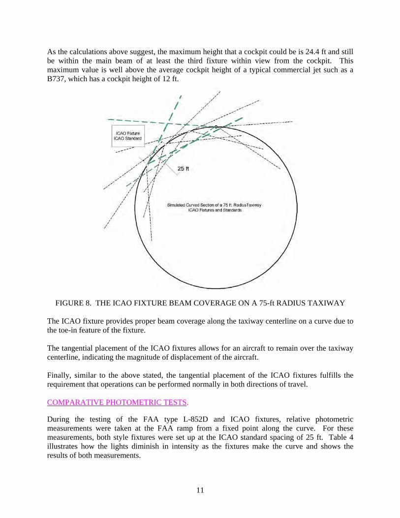
As the calculations above suggest, the maximum height that a cockpit could be is 24.4 ft and still be within the main beam of at least the third fixture within view from the cockpit. This maximum value is well above the average cockpit height of a typical commercial jet such as a B737, which has a cockpit height of 12 ft.
FIGURE 8. THE ICAO FIXTURE BEAM COVERAGE ON A 75-ft RADIUS TAXIWAY The ICAO fixture provides proper beam coverage along the taxiway centerline on a curve due to the toe-in feature of the fixture. The tangential placement of the ICAO fixtures allows for an aircraft to remain over the taxiway centerline, indicating the magnitude of displacement of the aircraft. Finally, similar to the above stated, the tangential placement of the ICAO fixtures fulfills the requirement that operations can be performed normally in both directions of travel. COMPARATIVE PHOTOMETRIC TESTS.
During the testing of the FAA type L-852D and ICAO fixtures, relative photometric measurements were taken at the FAA ramp from a fixed point along the curve. For these measurements, both style fixtures were set up at the ICAO standard spacing of 25 ft. Table 4 illustrates how the lights diminish in intensity as the fixtures make the curve and shows the results of both measurements.
11
TABLE 4. RELATIVE PHOTOMETRIC DATA
Relative Photometric MeasurementsLight No. ICAO FAA
1* 33.86 35.96 2 9.754 4.236 3 4.903 0.883 4 1.877 0.918 5 0.100 0.073 6 0.041 -------
*The first light fixture reading was taken for baseline purposes, from a fixture straight on.
Note that the photometric values for those lights beyond the first fixture, the photometric values for the FAA type L-852D fixtures are about half the value of the ICAO fixtures. The sixth FAA type L-852D fixture, at the proposed ICAO spacing, was not measurable.
CONCLUDING REMARKS From the results of this evaluation and a study of pertinent Federal Aviation Administration (FAA) Advisory Circulars (AC), the following conclusions were made. • The FAA type L-852D fixture, when placed at the International Civil Aviation
Organization (ICAO) spacing of 25 ft, did not maintain the minimum segment of three lights beyond the cockpit cutoff. While the third light was barely visible to observers, it photometrically did not meet the requirements of the FAA AC. In addition, any reduced visibility conditions would further diminish the performance of the fixtures. At 12.5 ft, however, sufficient fixtures were visible.
• The FAA type L-852D fixture, when placed at the ICAO spacing of 25 ft, provides some
visual information on the rate of change of direction of the curve. At the FAA spacing of 12.5 ft, however, the information is greatly enhanced.
• The FAA type L-852D fixture, when placed at the ICAO spacing of 25 ft, provides
marginal indication of the magnitude of any displacement of the aircraft from the taxiway centerline. At 12.5-ft spacing, however, the indication is much more accurate, as more fixtures are visible to the cockpit.
• The FAA type L-852D fixture operates normally in both directions of travel, as long as
they are installed properly and aligned per AC 150/5340-30, “Design and Installation Details for Airport Visual Aids.”
12
• The ICAO fixture, by design, allows a larger spacing since the light channels on the fixture, in each direction, are canted inward towards the curve. This allows for more of the fixture to be visible to the aircraft coming around the curve, especially in the lower visibility conditions associated with runway visual ranges (RVR) less than 1200 ft.
• The FAA type L-852D fixture, by design, requires the closer separation since the light
channels are aimed to the outside of the taxiway curve. In tight taxiway radii, this reduces the number of fixtures that are viewable to an aircraft coming around the curve.
• The design and performance of the FAA type L-852D fixture does not support its use at a
25-ft spacing in RVR conditions less than 1200 ft. • The ICAO fixture, when placed at the ICAO spacing of 25 ft, performs satisfactorily for
its intended purpose. It provides indication of displacement of the aircraft from the taxiway centerline, provides information of rate of change of direction of the curve, maintains the minimum segment of three lights beyond the cockpit cutoff, and operates normally in both directions of travel.
13/14


![RHYTHM Blues, Technic and Improv 1 F=IV. C=I · RHYTHM Blues, Technic and Improv 1 . Title: Finale 2001a - [Basic Note Values Chart 1One on One.MUS] Author: Carolyn Inabinet Created](https://img.pdfslide.net/doc/110x75/5e70d8dd63b4a20e16371066/rhythm-blues-technic-and-improv-1-fiv-ci-rhythm-blues-technic-and-improv-1.jpg)