Embed Size (px)
Citation preview

1
Mechatronic Design 18-578/24-778
Shingling Robot
Team D
Shingler on the Roof
Benjamin Shih
Ram Muthiah
Mark Erazo
Hao Wang

2
Abstract The goal of the Mechatronic Design project is to design and fabricate a robot who can lay
out shingles following industry standards. The task was to place seven shingles on a roof along
red chalk lines that were spaced half a foot apart and overlapping. The motivation behind the
project is because shingling deaths are the fifth most common source of industrial accidents.
Throughout the semester, Team D created an inexpensive robot that was able to quickly
dispense shingles. The low cost was due to a design decision to attempt performing the task
without pneumatics. The robot consists of a hopper system that loads individual shingles, a
feeder system that pushes the shingles out of the hopper, a dropper that catches and dispenses the
shingle in the appropriate location, and a chassis that moves around and allows the dropper to
drop in multiple locations. The team initially created a prototype and constructed new parts
iteratively. However, the feeder and hopper transition did not work properly due to unforeseen
difficulties with obtaining the appropriately-sized springs with the desired spring constants. In
the end, the robot was able to navigate the entire roof and drop the shingles using a manual feed.
Given additional time and resources, Team D believes that the design is still feasible, and that a
pneumatic-free shingling robot that matches the capabilities of the pneumatic robot can be
created.

3
Table of Contents
Project Overview 4
Design Requirements 4
Design Concepts 5
System Depiction 6
Functional Architecture 7
Physical Architecture 9
Subsystem Descriptions 10
Schematics 12
Software Pseudocode 13
System Modeling, Development, and
Performance
14
Issues Resulting in Innovation 16
Performance Evaluation 17
Conclusions and Future Work 18
Parts List 20

4
1 Project Overview
Shingler on the Roof targets and aims to improve the construction industry specifically
by reducing the casualty rates amongst rooftop construction workers. In 2012, the UK estimated
that two thirds of fatal injuries in the construction industry were accounted for by falls, being
struck by moving vehicles or objects, and being trapped under collapsed buildings. While the
loss of life is horrific, the economic impact due to falls in the construction industry are also quite
unbelievable. Nearly 400K working days were lost in the construction industry to injuries or
fatalities related to falls.
Our aim is the reduce the loss of life and the economic impact by fall related injuries and
fatalities. We plan to do so by automating the process of shingling a roof, one of the leading
causes of falls in the construction industry. By constructing a robot which will shingle a small
roof without human intervention, our group aims to produce data that will lead to the automation
of many tasks in the construction industry. This will in the long run, reduce the loss of life and
lessen the economic impact to the construction industry.
2 Design Requirements
Explicit requirements from the project specification are as follows:
1. Cover one half of a roof surface with seven shingles using conventional overlapping
pattern with ½-shingle row-to-row offset
2. Maintain a ½ inch gap between shingles in the same row
3. Robot does not fall off roof and the footprint is no larger than 2 feet x 2 feet
4. Initial emplacement takes less than 1 minute and shingle loading takes less than 30
seconds
5. Minimum roof pitch robot must function upon is 4/12 (18.43 degrees)
6. Deposit 7 shingles in conventional overlapping pattern in less than 3.5 minutes.
7. Straightness: less than +/- ¼ inch deviation from horizontal chalk lines
The implicit requirements we identified boils down to building a scalable robot. This is broken
down as follows:
1. Capable of shingling roofs of all sizes with varying widths and lengths (not limited to
shingling the testbed)
2. Would be able to move about the roof quickly (less than 2 minutes for 7 shingles)
3. Would be lightweight to facilitate speed requirement
4. Will not use any form of pneumatics (this design decision was based on our judgment
that pneumatics were costly, heavy, and required initial setup time)
Our main coolness factor stems from the last implicit requirement. Since our self-
constrained restriction was that the robot cannot use pneumatics, the robot must use a shingle
feeder system which in previous years have met with no success. Consequently, the shingle feed
will be our coolness factor. We plan for our shingle feed to based on tank treads and/or rollers
such that the robot can spit the shingle onto a conveyor.

5
3 Design Concepts
Our most significant design choice was the decision to avoid pneumatics. Because many
other groups had expressed interest in using pneumatically-actuated mechanisms in order to
manipulate and place the shingles, we wanted to try a unique and innovative approach to the
problem. Subsequently, we chose to meet the design requirements by first brainstorming a
mechanism that could be used to dispense the shingle. We discussed ideas such as dragging
individual shingles apart, vertical feeding that dispenses by pushing individual shingles into a
slot, and other potential ideas. In the end, we went with the spring-loaded hopper system that
uses a tread-based feeder system to dispense shingles from the top of the stack instead of the
bottom of the stack, in order to reduce the amount of friction and wear and tear on the robot.
A sketch of our second choice design can be seen in Figure 1. Initially, we wanted to use
a tread-based dispensing system that would separate the shingles using little pegs on the tread
belts, and release each shingle individually. In the end, we decided to feed our shingles from the
bottom up, using a spring-loaded dispensing system.
Figure 1: Initial feeder design using horizontally mounted treads to dispense shingles.
In contrast to other groups, we took a different approach to the project’s system design by
first constructing a prototype of our robot, primarily using acrylic, before making our actual
robot. Via this approach, we were able to test multiple iterations of our robot before converging
on a final design. In retrospect, while this method is great for revising and refining our ideas, it
turned out to be detrimental for our group because we underestimated the amount of time
required to make multiple iterations of various parts. Although we found many areas of
improvement and mistakes in our original design, we were rushed to finish our final product as a
result. However, extensive prototyping was a very valuable design experience and it should
definitely be done for any longer-term or product-driven projects because of the valuable
feedback and data generated from having multiple testing opportunities.
Another design feature that we aimed to implement was to make our robot as cheap and
low-cost as possible. Our robot is extremely light - not including the off-board power supply, it
weighs about 30 pounds. Many of the components are very light, but still remain sturdy enough
6
to support the weight of the shingles. The total costs that we have spent on the robot are not
accurately represented by our budget because of our design approach. In fact, much of our
budget goes towards materials for prototyping our robot design and trying various ideas. In its
current state, the actual cost of the robot is estimated to be about $450. As there are a few things
to fix, and a few materials that we would like to replace with stronger counterparts, a more
reasonable estimate would be approximately $600.
4 System Depiction
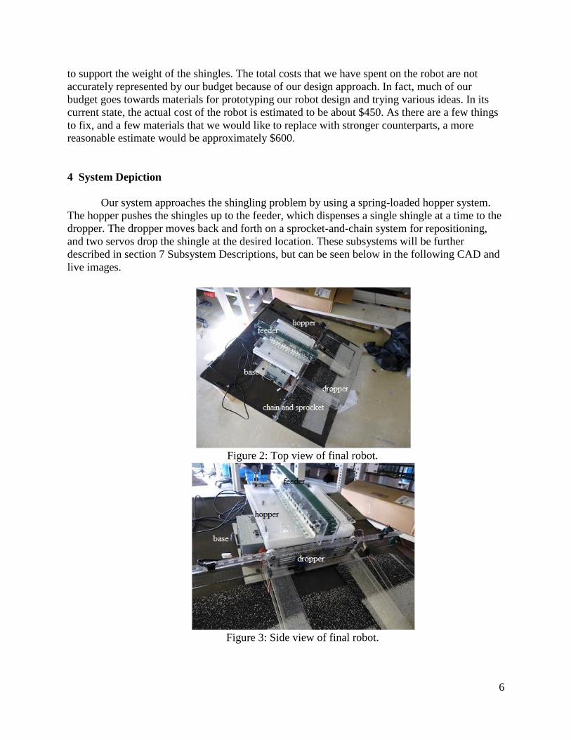
Our system approaches the shingling problem by using a spring-loaded hopper system.
The hopper pushes the shingles up to the feeder, which dispenses a single shingle at a time to the
dropper. The dropper moves back and forth on a sprocket-and-chain system for repositioning,
and two servos drop the shingle at the desired location. These subsystems will be further
described in section 7 Subsystem Descriptions, but can be seen below in the following CAD and
live images.
Figure 2: Top view of final robot.
Figure 3: Side view of final robot.

7
Figure 4: Isometric view of final CAD.
5 Functional Architecture
This is a diagram of our functional architecture. The only issue of note is that vision can
be ignored in this functional architecture as it has been replaced with dead reckoning. The
reasoning for this change is explained in the subsystem descriptions.

8
Figure 5: Functional architecture flow chart
The only condition to this functional architecture diagram is that the robot is placed
directly over the red chalk line 1.5 feet from the bottom of the roof and against the left edge of

9
the roof with the back IR sensor over the left roof edge. Both of these conditions are so that the
shingle that is dropped may line up with the bottom and left edge of the roof. Since vision is not
used anymore, the other significant requirement for initial placement is that the conveyor belt is
parallel to the bottom of the roof.
6 Physical Architecture
This is a flowchart of the physical architecture present on the robot. The CMUCam in this
physical architecture diagram is omitted from the final robot.
Figure 6: Physical architecture flowchart.

10
7 Subsystem Descriptions
Chassis
The chassis consists of a mobile base that moves the robot around on four wheels using
two-wheel drive. The chassis will house the drive motors, actuation motors, as well as the
electronics.
Figure 7: Side view of chassis CAD.
Figure 8: Front view of chassis CAD.
Hopper
The hopper's duty is to continuously ensure that a shingle is available for the feeder
subsystem. The hopper will push up on the bottom of the stack, such that one shingle is at the
same height as the feeder subsystem.

11
Figure 9: Hopper CAD.
Feeder
The purpose of the feeder is to push the top-most shingle from the stack into the dropper
subsystem. The feeder is the most precise part of our robot, as we only ever want a single shingle
being manipulated at one time. The feeder works by using a scooping arm, approximately the
same thickness as a shingle, to extend and push the shingle off the stack. We chose to push off
the top of the stack because there are fewer frictional forces applicable at the top.
Figure 10: Feeder CAD.
Computer Vision
We will implement line and grid detection using CMUCam4's processing capabilities
intertwined with Arduino. The camera will communicate with the rest of the system via serial,
and will indicate whether or not a shingle is ready to be dropped. The camera will also serve as a
failsafe for detecting whether or not the robot is still on the roof. Our robot can successfully
track the red line and apply rotational feedback to obtain a straight position. The feedback
controller is based on linear regression.
While this subsystem underwent significant amounts of development, we decided to not
use it in the end because dead reckoning turned out to be the simpler, efficient solution for this
given problem.The vision subsystem was eventually shelved due to issues with translational
feedback - combining the linear regression and subsequent repositioning with the constant
downward pull of gravity greatly complicated the controller design and information feedback

12
cycle. Since there was little to no slippage on the wheels, we decided to rely solely on dead
reckoning instead.
Dropper
The dropper's purpose is to release a shingle once it has received a positive signal from
the camera. Two servos, each with a panel such that the shingle is held up, are synchronously
actuated to rotate by 90 degrees. Subsequently, the shingle will fall.
Figure 11: Dropper CAD.
7a Schematics
Our final shingler robot contains 86 unique mechanical components. Due to space
constraints, individual images will not be included within the paper. The SolidWorks CAD files
are archived and available upon request.
We did not print any custom breakout boards, but instead assembled a few circuits on
perfboard for power regulation and dropper localization because it was quicker and cheaper than
printing custom boards. Below are the circuit schematics associated with each board.
Voltage Regulation
Our computer power supply could only provide voltages of 3.3 V, 5 V, and 11 V. The
voltages we needed were 5 V for sensors and Arduino, 3.3 V for select sensors, 8 V for VEX DC
motors for actuating feeder and dropper, and 24 V for actuating the DC motors used for
locomotion of the base. We purchased a boost converter circuit in order to obtain the 24 V, but
because we needed another converter in order to obtain the 8 V for the VEX DC motors, we
decided to make our own using a LM317 integrated circuit using the circuit topology below.

13
Figure 12: Voltage regulation for 11 V to 8 V for the VEX DC motors using the LM317
integrated circuit.
Dropper Localization
Sparkfun’s photo interruptor circuit is used in our dropper subsystem to detect the
position of the dropper with respect to the axis of the wheels. We placed a photo interruptor
sensor next to the wheel axis, and used a piece of metal attached to the dropper in order to
determine whether the current position was in the left-shingle, right-shingle, or center-shingle
dropping orientation.
Figure 13: Sparkfun’s photo interruptor circuit. The geometry of the sensor can also be referred
to as “slot sensor”.
7b Software Psuedocode
This is the pseudocode of the program running on the robot during the final system demo.
Initialize all variables and set 2WD motors to brake

14
Move conveyor to center of robot by powering DC motor for conveyor to 40% until IR sensor
goes below threshold limit
Use 2WD at 100% to move backwards on roof until back IR edge sensor goes low
Set left servo in dropper to 0 degrees and right servo to 180 degrees
Repeat three times or until forward IR sensor goes low
Turn on Feeder motor at 100% for 1000 ms
Delay 100 ms
Set both dropper servos to 90 degrees
Delay 500 ms
Set left servo in dropper to 0 degrees and right servo to 180 degrees
Use 2WD to move Forward at 100% for 3700 ms or forward IR sensor goes low
Use 2WD at 100% to rotate right for 1000 ms
Use 2WD at 100% to move backwards for 1500 ms
Use 2WD at 100% to rotate left for 1000 ms
Use 2WD at 100% to move forward on roof until forward IR edge sensor goes low
Repeat three times
Turn on Feeder motor at 100% for 1000 ms
Move conveyor to right side of robot by powering DC motor for conveyor to 40% until
right limit switch triggers
Set both dropper servos to 90 degrees
Delay 500 ms
Set left servo in dropper to 0 degrees and right servo to 180 degrees
Move conveyor to center of robot by powering DC motor for conveyor to 40% until IR
sensor goes below threshold limit
Use 2WD to move backwards at 100% for 3700 ms
Turn on Feeder motor at 100% for 1000 ms
Move conveyor to left side of robot by powering DC motor for conveyor to 40% until left limit
switch triggers
Set both dropper servos to 90 degrees
Delay 500 ms
Set left servo in dropper to 0 degrees and right servo to 180 degrees
8 System Modeling, Development & Performance
Many of our calculations and estimations were done in SolidWorks. Below are
descriptions and details for a few of the calculations that we did manually when constructing the
robot.
Spring Constant for Hopper Springs
One of the most tricky and careful calculations we needed to make was for the spring
constant of the springs. We wanted to ensure that each time a shingle was dispensed, the
remaining displacement was enough such that the rest of the stack of shingles was pushed to the
top of the hopper, in order to interact with the feeder’s tread belt.

15
For a single shingle,
original length = 1.25”
pushed to 5/56"
weight = 0.82286 lbs -> assuming 5 springs, each one will experience .164571428 lbs per spring
Figure 14: Online calculator used to find the spring constant required for the desired parameters.
For all 7 shingles,
original length = 1.25”
pushed to 5/6"
weight 5.76 lbs -> assuming 2 springs, each one will experience 1.152 lbs/spring
Using the same procedure as before, the resulting spring constant is ~323 N/m. Unfortunately,
the desired springs are really skinny and small.
Next step: add a block of acrylic on top of the springs to more evenly distribute the weight. We
have to include the weight of the 1/8" block of acrylic (arbitrarily decided on this thickness
because we already have some materials of that thickness) in addition to the stack of shingles.
dimensions of acrylic block: 12"x12"x1/8"
resulting volume: 18 in^3
density: .043 lbs/in^3
resulting weight: 0.774 lbs

16
revised spring constant calculations:
total weight of shingles + acrylic block: 6.534 lbs
-> 1.3068 lbs per spring (for 5 springs)
For all 7 shingles,
original length = 1.25”
pushed to 3/4"
weight 6.534 lbs, 1.3068 lbs per spring
---> K = 305.141 N/m
------> convert from N/m to lb/inches => .2248089 lbs/N * 1/39.3701 m/in * K = 1.742399
lb/inches
Miscellaneous
For these calculations, the numbers were not as complex and the work was unfortunately
not recorded. Below is an overview of additional calculations that were required for our robot to
function.
i. Voltage regulation for vex motors
In order to obtain the appropriate voltage output using the LM317, we needed to compute
the values of the resistors that we need. This was done based on an equation associated with the
circuit topology.
ii. Diameter of the base’s wheels
Our goal for the base was to keep it as low as possible to the ground. To do this, we
calculated the smallest diameter of the wheels that was feasible for our robot, keeping in mind
that the robot still needed to touch the floor while placed on an incline.
iii. Drilling mounting holes
While mounting our components together, we needed to figure out where to place each
component. In particular, the vex components required careful consideration for where to mount
individual components, such that the end result would allow us to successfully mount the
sprocket and chain, as well as the feeder tread components. These calculations were primarily
done using SolidWorks as a way to record where the holes should be drilled and cut.
8b Issues Resulting in Innovation Translation feedback in CMUcam
In the middle of the semester, after determining that our wheels were fairly precise in
terms of movement and slippage, we shelved our entire vision system in favor of using dead
reckoning, because we were unable to design a controller that accounted for both the linear
regression and the downward fall of the robot while it was fixing itself to be horizontal with the
red chalk lines. Our solution was innovative because it required us to quickly determine a fix that
would allow the robot to operate properly.
Weakness of individual dropper flippers

17
Initially, our design incorporated the flippers of the droppers without any support. After
beginning building, we realized that they were not sturdy enough on their own to hold up the
flippers. This revelation led to the design of the dropper support, which extends to both sides of
the flippers and provides structural support that holds up the dropper.
Wearing down of rubber wheels
Throughout the testing phase of our robot, we gradually began to notice that it was
slipping more and more. Curious, we tried various modifications until we finally realized that the
rubber wheels had slowly been grinding away, such that the un-actuated caster wheels were the
primary contacts with the ground rather than the rubber wheels. This meant that the robot was no
longer permanently in contact with the ground. In order to resolve this issue, we exercised our
creativity and decided to remove two of the unpowered caster wheels, while compensating for
the change in the drive system via software. This taught us the valuable lesson that when
possible, push issues to software, because it is much quicker, cheaper, and often simpler to
modify.
8c Performance evaluation
Performance Results
On demo day, everything except for the dispensing system worked. We were able to
move and drop shingles (with manual feeding to the dropper subsystem), and transition to a new
row in order to continue shingling. The robot was able to complete the shingling in
approximately 1 minute and 50 seconds, with high accuracy (no penalties as given by the
specifications). Unfortunately, on competition day, our robot had taken enough damage and
began to fall apart. The dropper ended up falling too close to the ground, so when the servos
actuated to open the fins and drop the shingle, the fins ended up getting caught on the floor and
becoming stuck.
Hopper Results:
The spring-loaded hopper works by finding an equilibrium point at all times between the
springs and the n remaining shingles. The spring constants of the springs are selected such that
the topmost shingle is always applying a light force to the treads, such that it can be dispensed.
As mentioned earlier, because we were unable to obtain a spring with both the appropriate
constant and width that we desired, we had to settle for springs of a larger diameter (in order to
properly support and distribute the weight of the shingles) but slightly different spring constant.
This decision turned out to be problematic because the springs ended up applying too much force
against the top surface of the hopper, such that the treads were not able to generate enough
orthogonal force to dislodge and dispense individual shingles.
Feeder Results:
The feeder is attached to the top of the hopper and is powered by a motor that spins a set
of treads. The treads grip onto the shingles and drag them out onto the dropper. The feeder did
not have enough traction on the tread-belt that we bought from vex, and unfortunately, because
18
the hopper had too much upwards force pushing against the belt, any materials we attached to the
tread in order to increase its friction were unable to withstand the wear and tear of repeated
traction and eventually fell off the belt.
Dropper Results:
The dropper can support the weight of a shingle dropped onto it, move to the correct
position via localization using button sensors, and drop the shingle using two mini-servos that
control flippers that hold up the shingle. The dropper was able to accurately place shingles within
the locations specified by the red lines, under less than 0.5” error on most trials.
Base Results:
The base ended up working very well, particularly for the transition to the second row.
Other than some minor issues encountered with the rubber wheels wearing away over time, the
base was fairly robust. Vertical slipping was not a huge problem as we slipped less than 0.5”
when traversing the roof horizontally.
Lessons Learned
While all of our subsystems functioned successfully, we were unable to integrate all of
them completely. In the end, we decided to shelve our vision system because the translational
feedback required to fight slipping down the incline was too difficult to solve from a controls
perspective while also optimizing for all of the other parameters.
In addition, we also had trouble properly integrating the feeder and hopper interfaces.
Even though the individual subsystems worked, the hopper springs we chose were too small and
thus we had to choose sub-optimal springs. However, these springs resulted in too much upwards
force, such that the friction forces between individual shingles was too much for our feeder's
tread motor to overcome.
The takeaway is that functional subsystems do not imply functional systems.
9 Conclusions & Future Work
Conclusions
Although our prototype was able to run the course very quickly due to its clean wheeled
locomotion, our unusable feeder made it impossible to run the course without any manual
intervention. As a result, we realized that we would have made several decisions very differently
given the ability to start from scratch or even redesigning the sub assemblies. Our current feeder
may have been able to work if we pulled from the bottom of the stack with much larger treads or
rollers with a much stronger motor. The Vex treads and links were not nearly sturdy enough to
separate the shingles and pull one out from a stack.
If we were to start from scratch, we would not deviate too much from our current design,
but we would definitely make several changes. The biggest change would be to make the whole

19
robot more robust and a little heavier as our current model was much too flimsy for prolonged
use. Our dropper, which was currently made of acrylic would have been made of wood or
aluminum in order to hold up the weight of the dropper fins and shingle. We would have made it
a little taller in order to put wheels under the fins to support the weight better and keep the fins
from touching the ground. The dropper would most likely have been controlled using actual bike
link chains and a DC motor to support the extra weight. Lastly the dropper servos would
definitely have been larger to ensure its ability to open and close completely despite the weight.
Our feeder would be very much like was stated above where the overall hopper and
feeder would be flipped and the feeder would pull from the bottom. If we could prearrange
shingles, we most likely have stuck with our initial idea of having them pre-separated in a mini
conveyor system. Overall our feeder and hopper would probably have been a little larger to
compensate for the stronger motors and rollers. We would also have supported this above the
robot a little better while distributing the weight evenly across the base as we noticed our current
design because our robots edges to bend inward and resulting in our ball transfers to stop the
drive wheels from touching the ground.
Lastly, our base would have been a little longer and thicker to compensate for the
previously stated changes and heavier overall weight. As a result our drive wheels would have
to be larger and our geared motor would have had to be much stronger. If we could have started
from scratch, these changes would have definitely allowed our robot to function better overall.
Individually as team members, we either learned new skills outside of our previous area
of expertise, such as wiring and using signal processing, or gained mastery in areas familiar to
us, such as using design software, machining, and coding an Arduino. The amount of work in
this project over the course of the semester forced us to push ourselves to learn through
exploration of new fields, implementing different design ideas, testing them out, and iterating or
fixing our problems.
As a group, we realized the importance of proper planning and designing as it has a huge
impact on the amount of work, time, and effort needed to complete any type of design project at
a given deadline. We also learned from the top group in the shingler competition the importance
of specialization and expertise. By learning from those who have succeeded before in previous
designs and dividing the work to those who have expertise in that area, you can create a design
and build it much quicker with a much lower chance of failure. Although these ideas seem very
basic, we believe they should definitely be stressed more as part of a design class. Ultimately we
learned a lot from the class and it was very worth all of our time. On a scale from 1 to 10, I
would say our design was only a 5 to design and implement. We did not make custom gears,
encoders, or complex parts which could move in two degrees of freedom. Seeing as we aimed to
make a simple compact design, we believe designing it was pretty straightforward; however the
small complications resulting from the flimsy parts caused us a lot of problems with
implementation.
Future Work
Many of the changes that we would make were stated in the previous section where we
make the robot slightly more robust. However, we would most likely put a plastic casing around
the robot from the dropper to the base in order to hide the wires. We also put a small control
panel and possibly a remote control to allow the user to control the robot’s functions and

20
settings. With full automation of machining, our robot could easily be mass produced with little
human work involved due to its simple design.
10 Parts List Vendor Part Quantity Unit
Price
Total
Price
Optically Clear Cast Acrylic Sheet 1/8" Thick, 12" X 24'' 2 $15.76 $31.58
General Purpose Low-Carbon Steel U-Channels - 3ft base1" legs1/2"
tol.±0.063" wall thick1/8"
1 $11.36 $11.36
Steel Drive Shaft 3/8" Dia. 12'' long 1 $6.62 $6.62
Zinc-Galvanized Perforated 90° Angles 6ft 1 $6.76 $6.76
rubber wheels 2 $2.79 $5.58
Compact dc gearmotors 2 $42.03 $42.03
Miniature Drive Shafts 5/16” diameter, 1 foot length 1 $10.94 $10.94
Shaft coupler 5/16”, without keyway, steel 2 $6.70 $13.40
WHITE Optically Colored Cast Acrylic Sheet 1/4" Thick, 12" X 24'' 1 $18.80 $18.80
Steel Ball Bearings 2 $4.41 $8.82
Extrusions for Aluminum T-Slotted Framing, 2 feet 1 $8.35 $8.35
Countersunk Flange-Mount Ball Transfers - type #14, 3/4" height (A), 11/16"
width (B)
4 $5.19 $20.76
Compression Springs (steel compression spring music wire, pack of 12, rate of
1.72, max load 1.40 pounds, )
1 $6.88 $6.88
WHITE Optically Colored Cast Acrylic Sheet 1/4" Thick, 12" X 24'' 2 $18.80 $37.60
Optically Clear Cast Acrylic Sheet 1/8" Thick, 12" X 24" 1 $15.76 $15.76
Boosts 12 V to 24 V for motor 1 $9.49 $9.49
12"x24"x0.25" Aluminum Bare Plate 6061 T651 1 $55.12 $55.12
Infrared Proximity Sensor - Sharp GP2Y0A21YK 2 $13.95 $27.90
Vex Sprocket & Chain Kit 1 $29.99 $29.99
Vex Additional Chain 1 $14.95 $14.95
2-Wire Motor 269 w/ Motor Controller 29 2 $19.99 $39.98
12"x24"x0.25" Optically Clear Acrylic 1 $28.08 $28.08
Servo A0090- Small 2 $8.95 $17.90
Vex Tank Tread Kit 1 $30.00 $30.00
Tamiya Connector Pack, Male 2 $2.25 $4.50
velcro for mounting electronics/power supply 1 $9.82 $9.82
Impact-Resistant Polycarbonate 4ft 1 $3.41 $3.41
Drive shaft 12" (4 pack) 1 $8.96 $8.96
Shaft Collar (16-pack) 1 $10.49 $10.49
3" overall length, .688" outer diameter, rate lbs/inch 1.90. package of 12 1 $6.44 $6.44
Optically Clear Cast Acrylic Sheet 1/4" Thick, 12" X 24'' 1 $28.08 $28.08
Surface-Mount Hinges Removable Pin—Style 1 1 $5.68 $5.68
Power Extension Cable 1 $6.90 $6.90
Optically Clear Cast Acrylic Sheet 1/4" Thick, 12" X 24'' 1 $28.08 $28.08
Arduino MEGA 2560 board 1 $39.95 $39.95
Total $644.34