Embed Size (px)
Citation preview

Team-LUX technical paper Page 1 of 20
Team-LUX DARPA Urban Challenge 2007
Technical Paper, June 1st, 2007
Martin Dittmer, Jörg Kibbel, Holger Salow, Volker Willhoeft
IBEO Automobile Sensor GmbH www.team-lux.com, www.ibeo-as.com
DISCLAIMER: The information contained in this paper does not represent the official policies,
either expressed or implied, of the Defense Advanced Research Projects Agency (DARPA) or the Department of Defense. DARPA does not guarantee the accuracy or reliability of the information in this paper.
Executive summary Team-LUX is Ibeo's team for the Urban Challenge 2007. It uses the "lynx", a VW Passat equipped with actuators and only three Laserscanners for the race. The Laserscanners are used for multiple purposes: obstacle detection, lane detection and IMU replacement. This reduction in system complexity allows the lynx operate on minimal processing power and appear just like an ordinary production vehicle.
1 Overview Team-LUX, the cooperation of Ibeo and Sick, is Ibeo’s first Grand Challenge team. However, Ibeo has been developing sensors and driver assistance systems for many years, so it is an interesting challenge to integrate both sensors and software into the most sophisticated driver assistance system possible: autonomous driving. Ibeo’s answer is Lux, the lynx.
2 Lux, the lynx
2.1 Body
Fig. 1: Lux the lynx, fully equipped with sensor
system and team leader
The robot is a production VW Passat B6 model. It is equipped with a 2.0 TDI engine, 140 hp. All sensors and actuators are fully integrated into the vehicle. For autonomous control, the production vehicle was retrofitted with steering, brake, accelerator and gearshift actuators. In addition, secondary functions like handbrake and indicators can also be automatically controlled.
2.1.1 Safety Our main focus is on safety. The robot resembles a production vehicle, without hard, sharp or rotating objects protruding from anywhere. Internally, all systems are

Team-LUX technical paper Page 2 of 20
cross-checking their function with other components and will go to a safe state in case of a malfunction. If the driver uses his internal emergency off switch, the whole sensor/actuator subsystem is made powerless and all systems immediately cease to interfere with the vehicle. This has allowed Ibeo to obtain a license for the robot to use it in public traffic, although with limited steering actuator capabilities.
2.1.2 Collar As the Lynx is an autonomous vehicle, a remote control is required for safe operation. A professional SafeStop ES-200 system from TORC Technologies is used to remotely set the vehicle to RUN, PAUSE or DISABLE mode.
2.2 Muscles The primary actuators of the lynx consist of electronic steering, brake, accelerator and gearshift. Secondary systems are handbrake and indicator control as well as the warning light and horn. Fig. 2 shows an overview of the overall actuation.
Fig. 2: Overview of vehicle control system
Backbone of the actuation is the SystemController. This controller is the interface between the application, the vehicle and the actuators. It also runs low-level control algorithms for the longitudinal
control of the vehicle. On the hardware side, the controller is a C161CS board with 2 CAN interfaces. The board has been extended with multiple buffered I/O-Ports. Since the lynx is also licensed for public traffic, the SystemController must guarantee validity of the requested action as well as its conformity to the current limits. These limits can be set by the application (e.g., an Adaptive Cruise Control (ACC) application would explicitly forbid steering control), but also by the driver via a switch panel. Setting the switch to "Public traffic mode" limits both steering power and speed to limits acceptable for public traffic. Outside of the Urban Challenge, this mode can be used for haptic feedback to the driver while leaving vehicle control with the driver at all times.
2.2.1 Steering Steering control is achieved with a special high-torque brushless-dc-motor, attached to the steering column with a chain drive. The motor will deliver a peak torque of 11.4 Nm, amplified to 16 Nm by the chain transmission. For driver convenience, it was designed with a high number of poles, ensuring that the driver will not feel mechanical interruptions when moving the steering wheel himself. The motor is controlled by a sine-wave motor controller running an adapted firmware. This firmware offers all control options required for safe and efficient operation of the steering motor. All access parameters can be limited to their absolutely necessary maximum in order to avoid surprises. Feedback about the steering operation comes both from the motor controller and the vehicle CAN bus. Comparing both sources of information allows the early recognition of possible errors. In case of a power failure, or an emergency-off, power is disconnected from the

Team-LUX technical paper Page 3 of 20
controller and the motor will turn freely. This is undetectable by the driver.
2.2.2 Accelerator Accelerator control is achieved by a "simulation" of the accelerator pedal. Therefore, the pedal is electronically disconnected from the vehicle and connected to the accelerator control instead, which in turn is connected to the vehicle. If no electrical power is applied, or no accelerator control is desired, the pedal has full control over the vehicle. If accelerator control is required, a relay will disconnect the pedal and an artificially generated signal is fed into the vehicle, simulating any desired pedal position. In case of a power failure, or an emergency-off, power is disconnected from the accelerator controller and the pedal is automatically connected to the engine control as if no controller was present.
2.2.3 Brake
Fig. 3: Accelnet motor controller, and Copley
linear motor
The brake is actuated by a linear "Servo
Tube" motor, connected to the brake pedal. The linear motor has a thrust rod that is free-moving when not controlled. Using this setup, a deceleration of at least -7 m/s² can be achived even on wet surfaces. Note that all assistance systems such as anti-blocking and stability systems are still actively supporting the lynx. On emergency off, both the power supply and the battery backup is disconnected from the motor controller, allowing the thrust rod to be pulled back to initial position by the brake pedal. The handbrake is always available as a secondary system.
2.2.4 Gearshift In the Passat B6, the gear selector is attached to the engine by a combination of mechanical and electrical connections. To move the gear from Park to any other position, a mechanical movement is required, while the transition between Neutral, Drive and Reverse is achieved by CAN commands. Since it is not required to move the gear to or from the Park position during the race, a purely electronic gear control was designed. Gear control can be taken over by removing the gear lever from the CAN bus, connecting it to Ibeos private communication bus instead. The SystemController now emulates the gear lever and generates the required messages for the vehicle. In case of a power failure, or during emergency off, gearbox control is automatically handed back to the lever.
2.2.5 Indicator and handbrake Both the indicators and the handbrake are controlled by emulating user action on the respective lever or switch, using the CAN bus interface. During longer standstill times, the handbrake is used releave the main brake actuator.

Team-LUX technical paper Page 4 of 20
2.3 Senses
2.3.1 Laserscanner Three Ibeo Laserscanners are the lynx' primary means for environmental perception. For the Urban Challenge, a prototype of Ibeos new Laserscanner, the LUX, is used.
Fig. 4: Prototype of the LUX (left), and the new
LUX sensor (right)
2.3.1.1 Technology The Ibeo Laserscanners use time-of-flight measurement principle with near-infrared light. The measurement range is at least 200 m, although vehicles and other well-reflecting objects are typically detected well beyond this distance. All Laserscanners are eye-safe.
Fig. 5: 4 individual scan planes.
Each LUX prototype provides a scan area of up to 240° with a horizontal resolution of up to 0.125°. Each sensor scans simultaneously in 4 scan planes, as shown in Fig. 5. Using the data
from all scan planes, both vehicle pitching and road slopes can be compensated by the processing software without ever losing contact to tracked objects.
2.3.1.2 Integration
Fig. 6: Integration of the Laserscanners in the
front and rear bumper
In the lynx, all three scanners are fully integrated (see images above). This limits the usable field of vision of the sensors; however, it has a huge safety advantage because no sharp or hard edges of the sensor are protruding from the vehicle contour, and the sensors are protected from accidental bumps and scratches.
Fig. 7: Scan areas of the integrated Laserscanners (red), forming a 360° field of vision. The relocated
parking aid detection area is shown in yellow.
Although, due to the integration of the scanners into the vehicle, the scan area of each scanner is not fully used, the overlapping areas still allow for perception all around the vehicle. The areas at both sides of the vehicle are covered by the

Team-LUX technical paper Page 5 of 20
ultrasonic sensors of the modified parking aid system. Additionally, all incoming objects are tracked even if they are temporarily lost from sight. As each scanner is mounted behind a protective plastic cover, dirt, dust or snow may gather on that cover during operation. Here, the Multi-Echo technology allows the sensor to work even if the cover is very dirty. Unlike most of the industrial Laserscanners, the LUX measures up to four consecutive distances with every single laser shot (see image below). This same technology allows the sensor to measure through rain, snow and fog.
Fig. 8: Scan data of a Multi-echo Laserscanner. Note that the object is still measured behind two
massive snow clouds.
2.3.1.3 Scan data A scan from the LUX prototype may consist of up to 970 measurements, each of which can measures up to 4 distances in the 4 scan planes. In total, a scan may have 15520 individual distances, so called scan points.
Fig. 9: Scan data including objects, ground and
lane markings.
The above image shows a typical scan from birdview perspective. Each of the colored dots is a scan point, with the color indicating the scan plane it was measured in: Red for the lowest plane, then blue, green and yellow for the topmost one. The measurements of the scan originate from several different type of sources: • Objects: These are "real" objects that are
present above the road level, such as cars, pedestrians, strawbales, or signposts.
• Lane markings: Lane markings have a higher reflectivity than the ground around them, so lane markings can be detected in the lower scan planes.
• Ground: When some of the scan planes measure to the ground, the ground is also picked up as scan data. This can be filtered out by software algorithms.
• Rain/Snow: When the light pulse hits a raindrop or a snowflake, a part of the energy may be deflected back to the receiver. If sufficient light is picked up, this results in a measurement that appears as noise in the scan. This noise can be filtered out by software algorithms.
In typical automotive applications, it is desirable to extract the scanpoints of the

Team-LUX technical paper Page 6 of 20
different sources from the scan. This is the task of the signal processing that is done before the high-level functions like object tracking and applications work with the data. During signal processing, the scan data is split into 3 groups: Objects, Ground (including lane markings) and noise (including rain and snow). The following processing steps then can decide which of the data to use for their task.
2.3.1.4 Lane detection Beside the classical object detection and tracking, the LUX prototype Laserscanner can be used for lane detection. As discussed in the previous section, parts of each scan typically contain information about the surface structure that can be extracted. However, this information is somewhat dependent on the vehicle movement and the road slope, so the reliability of this implicit information may not be enough for an application that requires knowledge about road layout and curvature. In order to achieve more robust results, a unique feature takes advantage of unused scan areas (when the sensor measures backwards into the car). For this segment of the rotation, the scan area is now deflected down to the ground in front of the vehicle using a dedicated mirror, forming 4 new scan planes. Fig. 10 shows this setup from side and top perspectives.
Fig. 10: Lane detection mirror setup, side and top view. The yellow scan areas are deflected down on
the ground by a mirror setup.
The scan data of these mirror areas are now measured with two different sensitivities, alternating from scan to scan: The first scan is measured with normal sensitivity, giving accurate range readings from the whole area. Using this data, road boundaries such as grass or curbstones can be detected. Then, in the second scan, sensitvity is lowered by the detection algorithm so that only the road markings (white or yellow lines) are left over in the mirror data. As there is a wide variation of both surface types and lane markings, the sensitivity level is not fixed but adjusted from scan to scan.

Team-LUX technical paper Page 7 of 20
Fig. 11: Lane detection on a German autobahn, using the deflected scan areas. Lane markings on
both sides are detected and assigned to a lane.
Fig. 12: Results of the lane detection on a German
autobahn
Based on these features, a lane departure warning system was developed by Ibeo as a sample application. This development showed that lane markings could be detected in 97% of the evaluated scans. In the remaining 3%, the markings were either of very poor quality or dropped due to ambiguity with other fragments on the surface, such as asphalt repair marks. The software side of the lane detection is discussed in detail in section 3.3.1.
3 The brain
3.1 ECU and processing overview
Although the Lux has built-in processing capabilities, all Urban Challenge application processing is done in two ECUs for easier programming.
Fig. 13: ECUs in the trunk of the lynx. The left two are used for processing, the next for visualisation. The rightmost one is the vehicle controller, using an ECU housing.
The standard ECU is a custom-built PC based on an ETX board. It is equipped with a passive-cooled Pentium M processor running at 1.8 GHz. The processor board is mounted on a mainboard equipped with multiple interfaces, such as Ethernet, ARCnet, CAN, USB, and RS232. The whole ECU is ruggedized for automotive use and does not contain moving parts.
Team-LUX technical paper Page 8 of 20
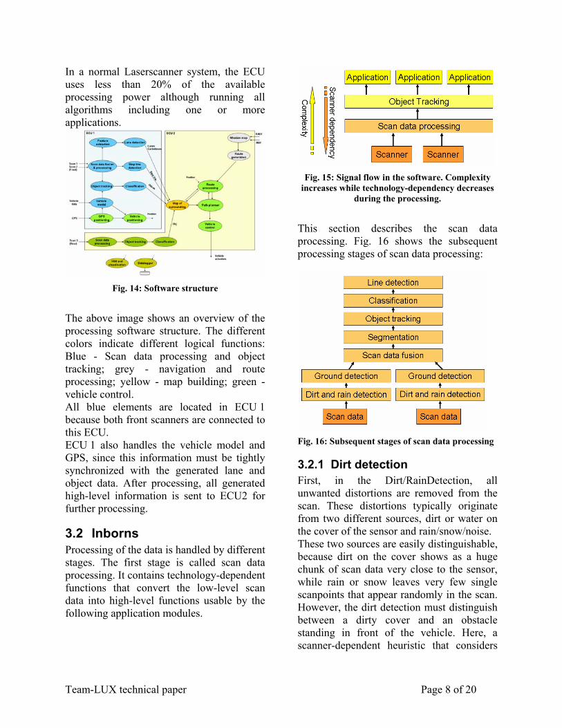
In a normal Laserscanner system, the ECU uses less than 20% of the available processing power although running all algorithms including one or more applications.
Fig. 14: Software structure
The above image shows an overview of the processing software structure. The different colors indicate different logical functions: Blue - Scan data processing and object tracking; grey - navigation and route processing; yellow - map building; green - vehicle control. All blue elements are located in ECU 1 because both front scanners are connected to this ECU. ECU 1 also handles the vehicle model and GPS, since this information must be tightly synchronized with the generated lane and object data. After processing, all generated high-level information is sent to ECU2 for further processing.
3.2 Inborns Processing of the data is handled by different stages. The first stage is called scan data processing. It contains technology-dependent functions that convert the low-level scan data into high-level functions usable by the following application modules.
Fig. 15: Signal flow in the software. Complexity
increases while technology-dependency decreases during the processing.
This section describes the scan data processing. Fig. 16 shows the subsequent processing stages of scan data processing:
Fig. 16: Subsequent stages of scan data processing
3.2.1 Dirt detection First, in the Dirt/RainDetection, all unwanted distortions are removed from the scan. These distortions typically originate from two different sources, dirt or water on the cover of the sensor and rain/snow/noise. These two sources are easily distinguishable, because dirt on the cover shows as a huge chunk of scan data very close to the sensor, while rain or snow leaves very few single scanpoints that appear randomly in the scan. However, the dirt detection must distinguish between a dirty cover and an obstacle standing in front of the vehicle. Here, a scanner-dependent heuristic that considers
Team-LUX technical paper Page 9 of 20
both distances and reflected energy is used. Fig. 17 shows a scan after this processing step.
Fig. 17: Scan data with activated dirt detection.
Dirt is marked as gray dots (at the sensor position).
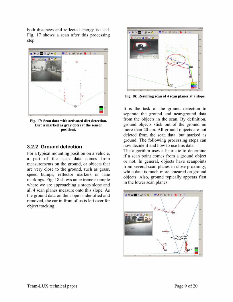
3.2.2 Ground detection For a typical mounting position on a vehicle, a part of the scan data comes from measurements on the ground, or objects that are very close to the ground, such as grass, speed bumps, reflector markers or lane markings. Fig. 18 shows an extreme example where we are approaching a steep slope and all 4 scan planes measure onto this slope. As the ground data on the slope is identified and removed, the car in front of us is left over for object tracking.
Fig. 18: Resulting scan of 4 scan planes at a slope
It is the task of the ground detection to separate the ground and near-ground data from the objects in the scan. By definition, ground objects stick out of the ground no more than 20 cm. All ground objects are not deleted from the scan data, but marked as ground. The following processing steps can now decide if and how to use this data. The algorithm uses a heuristic to determine if a scan point comes from a ground object or not. In general, objects have scanpoints from several scan planes in close proximity, while data is much more smeared on ground objects. Also, ground typically appears first in the lower scan planes.

Team-LUX technical paper Page 10 of 20
Fig. 19: Scan data after ground removal. Upper: Urban road, lower: rural road. Ground is shown as black dots; it is not used for object tracking.
Note the lane markings being detected and removed.
Fig. 20: Ground removal while the vehicle is
driving a rough road. Note the trees on the right-hand side of the road.
Fig. 19 shows typical street scenes; ground data is shown as black dots. In the right image, note the lane markings. These markings are clearly visible in the scan data, and marked as ground objects. Fig. 20 shows a scene from an unpaved side road where the vehicle is rolling and pitching heavily. Note that all trees are left untouched, being detected as objects.
3.2.3 Scan data fusion Since the lynx is equipped with 3 Laserscanners, data from these sensors has to be fused at some point during processing. Fusion is generally possible at several different levels: • Low level or "Scan data" fusion: Fusion
of the available sensor data at the lowest possible level.
• Mid level or "Object data" fusion: Fusion of processed data, before handing it to the application level
• High level or "Application" fusion: Fusion within the application, e.g. on behavioral level.
In the urban challenge project, a combination of low level or "Scan data" and mid-level fusion was chosen. The scan data of the two front scanners is combined low-level to form one new, artificial scan covering the view area of both scanners. This new scan covers 220° field of vision around the front of the vehicle (see Fig. 7).
Fig. 21: Scan data from left and right scanner
(top), and fused scan (bottom)
This low-level fusion is costly in terms of processing power, because a lot of data has to be evaluated and moved. However, the resulting scan gives a very precise overview

Team-LUX technical paper Page 11 of 20
of the area and is easy to evaluate by the following steps, without the risk of inconsistent data. The data from the rear sensor is merged on object level. Since there is only a small overlap in the scan areas of the front and rear sensors, there is little risk of fusing inconsistent objects. In any case, the data from the rear sensor is only evaluated for special situations such as oncoming vehicles from behind.
3.2.4 Segmentation The scan data from the three Laserscanners is now available as two scans, one fused from the data of the front sensors, and one from the rear scanner. Both scans are now segmented. In this processing step, clusters of scan data are isolated and grouped together into so-called segments. Each of these segments belongs to an object, and no segment contains scan data from more than one object. Note that an object may consist of multiple segments, but this association is done later during object tracking. Based on the segment data, movement information is generated in the following Object Tracking step.
3.2.5 Object tracking The object tracking is the heart of the scan data processing. It takes the segments as input and generates the objects. Objects are virtual entities that are tracked from scan to scan. Typically, one scan object corresponds to one "real" object. Fig. 22 shows a scene as seen by a Laserscanner with the corresponding object data. By tracking the objects from scan to scan, dynamic parameters like velocity and acceleration can be calculated for each object. These parameters become more stable the longer the object is tracked. By
itself, the object tracking can only determine the relative object movement. From the available tracking algorithms, a simple Center-Of-Gravity tracking was chosen for the Urban Challenge. This very basic method is based on tracking the movement of the center of gravity of the objects. The algorithm is robust, easy and reliable and requires very little processing power. However, velocity calculation is somewhat inaccurate if the shape of the associated segment(s) changes. All available tracking methods calculate object position and relative movement. For the classification, the absolute object velocity is an important criterion. It can be calculated if vehicle movement information of our own vehicle is also available. The vehicle movement must be highly accurate in order to achieve good results. Therefore, it is also required to run a matching vehicle model.
Fig. 22: Objects with relative velocities (unit: kph)

Team-LUX technical paper Page 12 of 20
Fig. 23: Objects with absolute velocities (in [kph]).
Reliable absolute velocities require an excellent vehicle model.
The above image (left) shows the object data with the corresponding relative velocity vectors. In the right image, the absolute velocity is also calculated.
3.2.6 Classification During the object tracking process, the scan data has been converted to high-level object information. Now, object parameters like position and velocity are known for further processing. But some applications also require information about what the scanners have seen around the vehicle. For example, during the Urban Challenge, cars on the road have to be distinguished from other objects.
Fig. 24: Classification process (simplified).
The classification algorithm uses multiple feature extractors and a weighing system to sort all objects into either TRUCK, CAR, BORDER, LANE, SMALL or BIG. The two classes SMALL and BIG collect all objects that do not fit into any other class. A classical example of a BIG object is a wall, while a tree or a pole would become SMALL objects.
3.3 Thinking This "Thinking" section describes processing steps that use the high-level data generated during object tracking to create actual system behaviour. This is typically a driver assistant system for automotive applications; however, in the case of the Urban Challenge, it is the control of the autonomous vehicle, performing the required missions.
3.3.1 Lane detection One of the important requirements in the Urban Challenge is the ability to localize the lane and keep the vehicle in this lane. Therefore, a special lane detection algorithm is used. The lane detection consits of three different information sources: • Lane markings on the ground • Ground data • Objects on and beside the road In the first step, each one of these sources

Team-LUX technical paper Page 13 of 20
generates identical data in the form of the position of the vehicle in the lane. Then, a fusion algorithm merges this data into the final position information that is used for vehicle control.
3.3.1.1 Lane markings on the ground The principle of lane marking detection with Laserscanners has already been discussed in section 2.3.1.4. However, the feature extraction only delivers raw data in terms of possible lane markings that have been detected in the current scan. During the lane detection, energy information about the picked-up light of each scanpoint (so-called Echo Pulse Widths) is used to increase the robustness of the detection.
Fig. 25: Lane detection on a German autobahn. All lane markings are detected and assigned to a lane.
A Kalman filter then turns this feature information into reliable distance information, filtering out noise and missing detections. The result of this filtering is the position of both the left and right lane marking, with a distinction between broken or continuous line.
3.3.1.2 Ground data As discussed in section 3.2.2, data not coming from objects is marked as "ground" in the scan data. Although this data is not used for object detection, it still contains information about reflections coming from the ground. During lane detection, this data
is evaluated for longitudinal patterns that originate from lane markings on the ground (an image was also shown in section 3.2.2). Such patterns are found typically 10 - 30 meters in front of the vehicle, giving this module a longer foresight than the lane marking detection of the previous section. The drawback is that the ground data is very dependent on both the surface structure and the vehicle pitching, so data from the ground detection is generally less reliable than the data from the dedicated lane marking detection.
3.3.1.3 Objects The object data forms an excellent basis for lane detection. A human driver can navigate his vehicle without looking at the road by just using knowledge about how poles, traffic lights, bushes and other objects are located with respect to the road, or simply by following other vehicles. In the same way, the object-based lane detection evaluates all available object data for road boundaries and lane information. In urban and rural scenarios, this gives excellent lane information for the vehicle control.
3.3.1.4 Online map To detect the driveable path in the surrounding of the car not only the information of the current scan is used but also the the history of previous measurements. To combine these informations a special form of occupancy grids, based on a binary bayes filter, is used. An area of 50 x 50 meters around the vehicle is parted into so-called grid cells. The measurements of the current scan are transformed into the so-called measurement grid. For each measurement point in a cell mj, the value 0.05 is added to the cell likelihood p(mj). The value 0.05 is a heuristic parameter determined from extensive test drives. For each measurement in a scan, it is known that the line of sight

Team-LUX technical paper Page 14 of 20
between the Laserscanner and the object is free of obstacles. But no information is available about the area behind the object. Therefore, the cells behind objects keep there initial likelihood of occupancy p(mo) = 0.5. To combine the information of the current scan stored in the measurement grid and the history of previous scans stored in the online map, a binary bayes filter is used. The probability of occupancy is calculated considering all preceding measurements
),...,|( 11 −ti zzmp and the current probability )|( ti zmp with formulas (1) and (2).
SSzzmp ti +
=1
),...,|( 1 (1)
),...,|(1),...,|(
)|(1)|(
11
11
−
−
−⋅
−=
ti
ti
ti
ti
zzmpzzmp
zmpzmpS (2)
Note that the cells of the online map have to be moved with the vehicle, using data from the vehicle model as input. The image below shows an example of the online map. The driveable area is marked white. The higher the probability of occupancy, the darker the area in the map. Our test vehicle - in the center of the map - is marked red.
Fig. 26: Image of test drive area (top), and
generated online map (bottom). Driveable areas are marked white.
3.3.1.5 Lane fusion The lane fusion uses the output of all four lane detection algorithms and combines them into one set of consistent lane boundaries, and an estimation about the road curvature ahead.
3.3.2 Route processing and navigation
The route processing subsystem handles all mission issues, from reading the RNDF ("Route Network Definition File") and MDF ("Mission Data File") to creating the driving route. The first step is to read and parse the RNDF. A navigation map is created from the RNDF information and then transformed from the given global lat/long coordinates into a local x-y-coordinate system. This map is then extended by analysing the road network. Right-of-way rules are created at intersections and implicit waypoint connections are made. The image below shows the navigation map created from the Team-LUX Site Visit RNDF.

Team-LUX technical paper Page 15 of 20
Fig. 27: Mission Map
After the RNDF, the MDF is read and parsed. The MDF is split in two sections. The first section creates a mission route by stating the sequence of mission checkpoints to reach. The second section gives speed limits - both upper and lower - for road segments from the RNDF. These speed limits are added to the navigation map. After the mission is known, a mission route can be generated. This is done by finding the shortest connections between the required checkpoints, considering both distance and speed limits. In the final step, the mission route is checked for "far" waypoints, meaning waypints that are far away from each other. As no distance is guaranteed between any two waypoints, subsequent waypoints may be far away from each other. In this case, artificial waypoints are created and inserted inbetween the far-away waypoints, closing the gap. The location of these new waypoints is calculated by interpolating between the map waypoints, so their location is probably off the lane. But since all waypoints may be inaccurate, both
the map points and the fill points have to be moved onto the lane anyway. However, this is done locally while driving the mission and does not concern the navigation unless the route happens to be impassable. In the case of an impassable connection, the vehicle control subsystem reports that the desired next waypoint is not reachable. The navigation system then marks the section as temporarily unavailable, and re-plans the route. Assuming a route has been found, the vehicle then proceeds on the new course.
3.3.3 Localisation and vehicle model
Precise localisation is one of the key issues for autonomous driving. The lynx uses 3 senses for localisation: • GPS: An OmniStar GPS system is used
for precise global positioning. • Vehicle data: Data received from the
vehicle onboard sensors is processed to determine the local vehicle movement.
• Scan data: Data from the Laserscanners is used as an additional source to determine the local movement of the vehicle. This process is discussed in detail in the following section.
Since all three sources deliver their information asynchronously, in different formats and with varying accuracy, an underlying vehicle model has to fuse the incoming data into a reliable vehicle position. It removes noise and allows the other processing systems to access the vehicle movement asynchronously.
3.3.3.1 Inertial Measurement Unit Typical localisation systems use at least one inertial measurement unit (IMU) to accurately extrapolate vehicle movement from the last known position, both between GPS measurements and during GPS outages. The quality of the IMU determines the

Team-LUX technical paper Page 16 of 20
accuracy and possible duration of the extrapolation. The major drawback from this solution is that an accurate IMU is an expensive piece of equipment to have onboard a vehicle. The lynx does not use an IMU. Instead, the Laserscanner data is used to monitor the vehicle movement. Since the Laserscanners have excellent range and angle measurement accuracy, the resulting movement information is of very high quality and can be extrapolated indefinitely without adding up drift errors. The only assumption is that there are at least two stationary objects to track, but with a a sensor range well beyond 200 m, unless driving takes place in the middle of a salt lake, this should not really be a constraint. The images below show the movement tracking process: The system locks onto stationary objects extracted from the scan data, and tracks their movement from scan to scan. By a reverse transformation, our own movement can be derived from the relative object movement.
Fig. 28: Movement tracking using features in the scan data: The system locks onto features (upper image), and calculates its own relative movement
from the movement of the features.
As an extension of this algorithm, Ibeo has also developed localisation algorithms that use known local features for global localisation of the vehicle with cm accuracy. These algorithms were successfully used for localisation on intersections in intersection safety projects. However, since the Urban Challenge track is not known in advance, no map of known features is avilable before the race. Therefore, these algorithms are not used for the lynx.
3.3.4 Mapping All information gathered by the onboard sensors is collected in the map of the surrounding. This map is a list of objects and features that covers the area around the vehicle. Inputs to this map are: • Objects • Lane markings • Road boundaries (such as curbstones) • Stop lines • Zone boundaries Note that the map contains different kinds of objects: • Normal or "real" objects. They are
detected in every scan of the Laserscanners and are updated with new data after every scan
• Ghost objects. Ghost objects are objects that have been tracked, but are no longer detected by the sensors. Curbstones typically fall into this category: They are detected in front of the vehicle, but once they come near the vehicle, they are lost from view. Still, they are there and tracked without being detected as they form a barrier for the vehicle movement.
• Virtual objects. Virtual objects are artificially generated objects that need to be considered for path planning. Zone boundaries fall into this category.
• Features. Features consist of information that give navigation hints without a critical need to consider them

Team-LUX technical paper Page 17 of 20
in navigation. Features include stop lines or lane markings.
Unlike the navigation map, the map of the surrounding is kept in the coordinate system of the vehicle. The major advantage is that this allows an easy path planning, at the cost of updating the map with every movement of the robot. Again, a good vehicle model is the key to a robust feature map. Unlike the "real" objects that are detected with every scan of the Laserscanners, some of the features will drift out of the field of vision, but must still be tracked while they are in range. The curbstones are of this type: They are detected in front of the vehicle, but must be kept in the map until the vehicle is way past them. Especially during slow-speed manouvers like U-turns or parking, it can be tricky to move these objects with the required accuracy to avoid drifts. Information is entered into the map only if the corresponding distance is 50 m or less; equally, information is removed when its distance is above 50 m.
3.4 Instincts Once all required information is present, it is time for the instincts to kick in: The lynx must move. Ibeo is working for years on advanced driver assistance systems and has several systems ready for use: • Adaptive Cruise Control including Stop
& Go driving and Navi map support • Lane Keeping • Lane Departure Warning • Intersection Safety • PreCrash • Automatic Emergency Braking • Low Speed Collision Avoidance • Pedestrian Protection For the lynx to move, several of these systems were modified to work not in a driver-controlled environment but in an
autonomous vehicle. By adding a navigation module and vehicle actuators, the lynx is ready.
3.4.1 Emergency stop Before any path processing is done, all tracked objects are fed into the Automatic Emergency Braking (AEB) module. This module is the basic active safety system of the lynx. The AEB module extrapolates both the object and lynx's current behaviour to anticipate future collisions. As this extrapolation becomes increasingly uncertain with longer extrapolation time, this foresight must be limited as much as possible to avoid false alarms. Considering the lynx deceleration capability of at least -7 m/s² on wet surfaces, a foresight of 2 seconds is sufficient for emergency braking on all objects that are not actively approaching. This time is extended to 5 seconds by a warning function that, based on the same processing, causes a speed reduction should a potentially dangerous situation be detected. If the situation clears, the warning is released and normal driving restored.
3.4.2 Path planning As soon as navigation has figured out a mission route, it is the job of the path planning to find a local path to the next waypoint. To do that, the path planner has knowledge about the current state of the vehicle as well as its physical abilities. The first step of the path planner is to convert the artificial navigation waypoints into a driveable path. This is done by filling up possible gaps as RNDF waypoints may be far apart from each other, insuring that the gap between subsequent waypoints is no more than 5 m. Next, the created path has to be projected

Team-LUX technical paper Page 18 of 20
onto the real road. To do so, the path planner uses the input from lane detection as well as the positioning information.
Fig. 29: Planned path, including a passing
manouver around a parked car
In this step, the path may both be shifted to the correct position as well as altered to fit each curve radius. Now the physical abilities of the lynx have to be taken into account. Impossibly narrow curves are relaxed to fit the steering capabilities, and the set speed of each waypoint may be lowered if the cross acceleration limits would be exceeded. Once the physical characteristics are set, the path is checked for consistency. This removes all rapid speed changes to allow for a safe and controlled ride. The result is a driveable path that fits the current lane. However, several situations exist that require deviant behaviour. The most prominent one is a simple standing obstacle in the path.
3.4.2.1 Obstacle in the path In the case of an obstacle in the path, there are two possible ways of handling the situation. The lynx can either adapt its own speed to keep a safe distance behind the obstacle. This "ACC" mode (in accordance to the Adaptive Cruise Control system) is
activated if it is undesirable to pass the obstacle, e.g. in safety areas, near curves or simply if the obstacle is too fast for safe passing. The underlying ACC Stop&Go module is readily available for all speeds and situations. If the obstacle is standing, the only option is to pass it. In this case, the original path is adapted sideways to pass the obstacle in accordance with the DARPA rules, keeping safe distances and respecting oncoming traffic before moving onto the passing lane. This is also done in safety areas after an excessive time delay has passed without movement of the obstacle.
3.4.2.2 Road block If both the path and possible passing lanes are blocked, none of the passing strategies will work. In this case, the path planning reports a road block to navigation and requests a new mission route. This new route starts at the current vehicle position and continues the mission, but the map data is now modified by the roadblock. Note that this modification is temporary so that in case no mission route could be found, "old" roadblocks can be removed to explore possible routes. Typically, the vehicle will need to perform a U-turn to continue the mission, unless it stands at an intersection where a simple left or right turn may lead onto the new path.
3.4.2.3 Intersections, 4-way-stops and stopsigns
In the previous examples, the path of the vehicle had to be modified to clear the situation. In the case of intersections, this is not the case; the vehicle can always move on the planned trajectory, as long as the vehicle speed is controlled. A typical example is a 4-way-stop, no matter if we are tuning left or right or simply crossing it. Here, the path on the road is unaltered, but the vehicle must stop at the stop line, and may be required to

Team-LUX technical paper Page 19 of 20
wait for other vehicles to clear the intersection.
Fig. 30: Intersection from DARPA sample RNDF. Each red dot at the entries represents a decoded right-of-way rule. Note the one-way road that needs not to be observed (=gray dots).
To handle these situations correctly, right-of-way information is generated during the map building process. Each route waypoint contains information about all inbound connections to this point, including right-of-way for all connections. When approaching such a waypoint, the right-of-way module automatically monitors the surrounding for both stop lines and incoming cars. The speed of the lynx is then reduced to stop at the stop line, and is only restored to cruise speed when it is our turn to pass the intersection.
3.4.3 Vehicle control After the path planning has found the optimal way, it is the task of the vehicle control module to move the lynx along the path. The input is a list of "trajectory points" (TP). Each of these points contain its position in vehicle coordinates, a set velocity and additional information, e.g. for indicator activation during turns or delay times. The controller now controlls the actuators to move along the path. A PID algorithm
controlls the steering system, while the longitudinal control is handled with a velocity interface.
4 Current work Although Lux, the lynx can find his way along the course, he still has to learn a few tricks:
4.1 Multi-lane roads Currently, the lynx can move along two-lane streets, with one lane for each direction. It has yet to learn driving on multi-lane roads, where more than one lane can be used in one direction. However, the required elements are available: • Routing on multi-lane segments • Detecting gaps in the traffic flow • Lane-change manouver, including
indicators By combining these elements in the Path Planning section of the software, the lynx will learn the required manouvers.
4.2 Zones Zones are areas in which the vehicle is not limited to lanes or road boundaries, but may freely choose a path to its destination. Typically, zones include a parking space into which the vehicle must be moved.
4.2.1 Route planning During route planning, zones are used just like road segments. Zone entries and exits connect parts of the road network and may be used for driving. However, once inside a zone, the vehicle movement is limited by the zone boundaries which must no be crossed unless to exit the zone at designated exits. Therefore, a virtual object is created once the vehicle is inside a zone. This object, called a "soft object", is treated by the software like

Team-LUX technical paper Page 20 of 20
any other object, so the vehicle must not collide with it or even get very close to it.
Fig. 31: Navigation routes inside a zone (from the
DARPA sample RNDF)
4.2.2 Other traffic As on the roads, other vehicles may also move inside the zones. Therefore, the lynx must adapt its route dynamically to avoid collisions and still find a path to the destination. A prediction of the object movement helps to react quickly and in an appropriate way.
4.2.3 Parking Spots, special waypoints inside Zones, are the only places where the vehicle may park. Spots are identified by their GPS position. The vehicle needs to navigate across the zone to the "entry" spot, and then advance to the second "park" spot. It then uses its rear Laserscanner to watch the other traffic for an opportunity to reverse out of the spot again.
5 Conclusion Ibeo is proud to have Lux, the lynx. For the first time, Ibeos wide range of Advanced Driver Assistance Systems have been combined into the ultimate Assistance System: a fully autonomous vehicle. The used Laserscanners have been extended to allow for both long-range object detection
and monitoring the ground for lane boundaries. This technology allows the lynx to rely on only 3 Laserscanners for both object and lane detection - a great reduction in overall system complexity. Beside the function itself, a major focus is on the design, to clearly demonstrate the achived state of technology. The result is a street-legal car that still has all potential for autonomous driving.
So... Team-LUX is ready to go!