Embed Size (px)
Citation preview
Refer to the QuickLIT Web site for the most up-to-date version of this document.
TEC Series BACnet® MS/TP Network Temperature and Humidity ControllersTechnical Bulletin
Code No. LIT-12011592Issued March 4, 2013
Supersedes May 13, 2011
Introduction . . . . . . . . . . . . . . . . . . . . . . . . . . . . . . . . . . . . . . . . . . . . . . . . . . . . . . . . . . 3
Related Documentation. . . . . . . . . . . . . . . . . . . . . . . . . . . . . . . . . . . . . . . . . . . . . . . . . 4
Product Overview . . . . . . . . . . . . . . . . . . . . . . . . . . . . . . . . . . . . . . . . . . . . . . . . . . . . . 6
Connecting the MS/TP Bus. . . . . . . . . . . . . . . . . . . . . . . . . . . . . . . . . . . . . . . . . . . . . . 6
MS/TP Controller Mapping . . . . . . . . . . . . . . . . . . . . . . . . . . . . . . . . . . . . . . . . . . . . . . 8
Preparation . . . . . . . . . . . . . . . . . . . . . . . . . . . . . . . . . . . . . . . . . . . . . . . . . . . . . . . . . . . . . . 8
Adding a Controller . . . . . . . . . . . . . . . . . . . . . . . . . . . . . . . . . . . . . . . . . . . . . . . . . . . . . . . 8
Adding Point Objects . . . . . . . . . . . . . . . . . . . . . . . . . . . . . . . . . . . . . . . . . . . . . . . . . . . . . 9
Troubleshooting . . . . . . . . . . . . . . . . . . . . . . . . . . . . . . . . . . . . . . . . . . . . . . . . . . . . . 10
MS/TP Bus Objects Tables . . . . . . . . . . . . . . . . . . . . . . . . . . . . . . . . . . . . . . . . . . . . . 11
TEC26x6(H)-4 and TEC26x6H-4+PIR Series Thermostat Controllers . . . . . . . . . . . . . . 11
TEC2645-4 Thermostat Controller . . . . . . . . . . . . . . . . . . . . . . . . . . . . . . . . . . . . . . . . . . 18
TEC26x7-4 and TEC26x7-4+PIR Series Thermostat Controllers . . . . . . . . . . . . . . . . . 22
TEC2601-4 and TEC2601-4+PIR Thermostat Controllers . . . . . . . . . . . . . . . . . . . . . . . 26
TEC2602-4 and TEC2602-4+PIR Thermostat Controllers . . . . . . . . . . . . . . . . . . . . . . . 29
TEC2603-4 and TEC2603-4+PIR Thermostat Controllers . . . . . . . . . . . . . . . . . . . . . . . 33
TEC2613-4 and TEC2613-4+PIR Temperature and Humidity Controllers . . . . . . . . . . 37
TEC2604-4 and TEC2604-4+PIR Thermostat Controllers . . . . . . . . . . . . . . . . . . . . . . . 41
TEC262xx-0+PIR Thermostat Controllers . . . . . . . . . . . . . . . . . . . . . . . . . . . . . . . . . . . . 44
1TEC Series BACnet® MS/TP Network Temperature and Humidity ControllersTechnical Bulletin

TEC Series BACnet® MS/TP Network Temperature and Humidity Controllers Technical Bulletin2
TEC Series BACnet® MS/TP Network Temperature and Humidity ControllersTechnical Bulletin
IntroductionThis document describes how to configure the various TEC Series Network Temperature and Humidity Controllers for BACnet® Master-Slave/Token-Passing (MS/TP) networked applications, including how to:
• connect to the MS/TP Bus and map a controller into a Network Automation Engine (NAE)
• add a controller
• add point objects
• override via the NAE
• troubleshoot the controller
TEC Series BACnet® MS/TP Network Temperature and Humidity Controllers Technical Bulletin 3
cument mber-12011587
-12011586
-12011584
-12011585
-12011692
-12011839
-1900620
-1900619
-1900617
-1900618
-1900690
-1900813
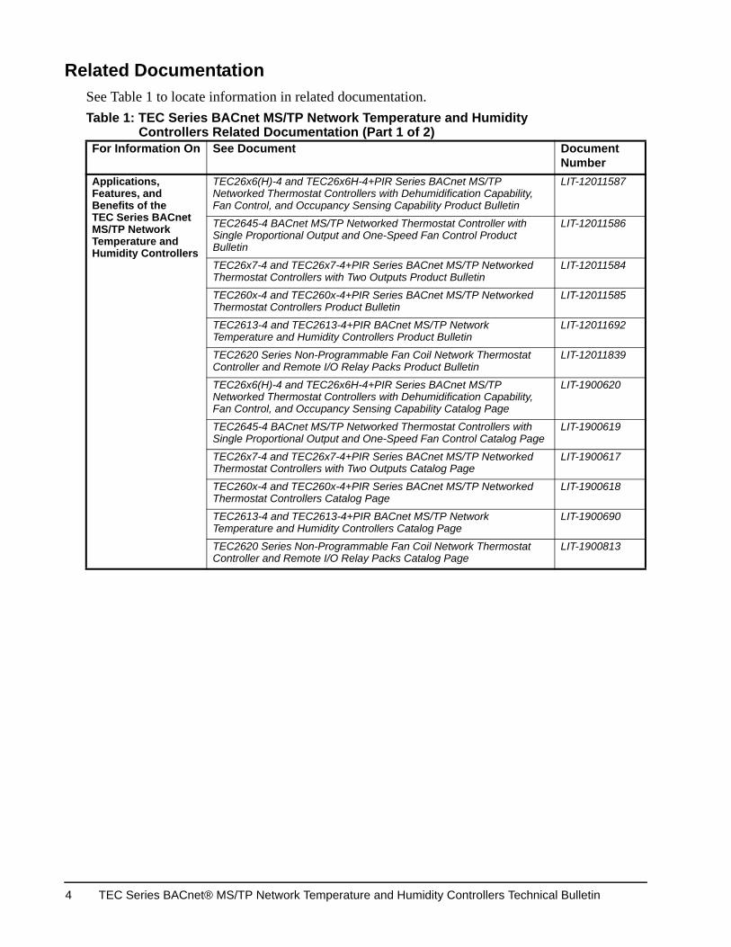
Related DocumentationSee Table 1 to locate information in related documentation. Table 1: TEC Series BACnet MS/TP Network Temperature and Humidity
Controllers Related Documentation (Part 1 of 2)For Information On See Document Do
NuApplications, Features, and Benefits of the TEC Series BACnet MS/TP Network Temperature and Humidity Controllers
TEC26x6(H)-4 and TEC26x6H-4+PIR Series BACnet MS/TP Networked Thermostat Controllers with Dehumidification Capability, Fan Control, and Occupancy Sensing Capability Product Bulletin
LIT
TEC2645-4 BACnet MS/TP Networked Thermostat Controller with Single Proportional Output and One-Speed Fan Control Product Bulletin
LIT
TEC26x7-4 and TEC26x7-4+PIR Series BACnet MS/TP Networked Thermostat Controllers with Two Outputs Product Bulletin
LIT
TEC260x-4 and TEC260x-4+PIR Series BACnet MS/TP Networked Thermostat Controllers Product Bulletin
LIT
TEC2613-4 and TEC2613-4+PIR BACnet MS/TP Network Temperature and Humidity Controllers Product Bulletin
LIT
TEC2620 Series Non-Programmable Fan Coil Network Thermostat Controller and Remote I/O Relay Packs Product Bulletin
LIT
TEC26x6(H)-4 and TEC26x6H-4+PIR Series BACnet MS/TP Networked Thermostat Controllers with Dehumidification Capability, Fan Control, and Occupancy Sensing Capability Catalog Page
LIT
TEC2645-4 BACnet MS/TP Networked Thermostat Controllers with Single Proportional Output and One-Speed Fan Control Catalog Page
LIT
TEC26x7-4 and TEC26x7-4+PIR Series BACnet MS/TP Networked Thermostat Controllers with Two Outputs Catalog Page
LIT
TEC260x-4 and TEC260x-4+PIR Series BACnet MS/TP Networked Thermostat Controllers Catalog Page
LIT
TEC2613-4 and TEC2613-4+PIR BACnet MS/TP Network Temperature and Humidity Controllers Catalog Page
LIT
TEC2620 Series Non-Programmable Fan Coil Network Thermostat Controller and Remote I/O Relay Packs Catalog Page
LIT
TEC Series BACnet® MS/TP Network Temperature and Humidity Controllers Technical Bulletin4
rt No. -9890-1001
rt No. -9890-1028
rt No. -9890-1036
rt No. -9890-1044
rt No. -9890-1052
rt No. -9890-1060
rt No. -9890-1389
rt No. -9890-1079
rt No.-9890-1427
rt No. -9890-870
-12011589
-12011588
-12011594
cument mber
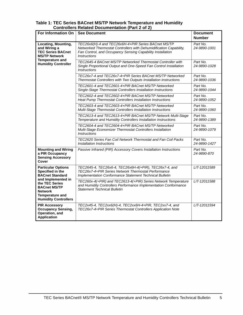
Locating, Mounting, and Wiring a TEC Series BACnet MS/TP Network Temperature and Humidity Controller
TEC26x6(H)-4 and TEC26x6H-4+PIR Series BACnet MS/TP Networked Thermostat Controllers with Dehumidification Capability, Fan Control, and Occupancy Sensing Capability Installation Instructions
Pa24
TEC2645-4 BACnet MS/TP Networked Thermostat Controller with Single Proportional Output and One-Speed Fan Control Installation Instructions
Pa24
TEC26x7-4 and TEC26x7-4+PIR Series BACnet MS/TP Networked Thermostat Controllers with Two Outputs Installation Instructions
Pa24
TEC2601-4 and TEC2601-4+PIR BACnet MS/TP Networked Single-Stage Thermostat Controllers Installation Instructions
Pa24
TEC2602-4 and TEC2602-4+PIR BACnet MS/TP Networked Heat Pump Thermostat Controllers Installation Instructions
Pa24
TEC2603-4 and TEC2603-4+PIR BACnet MS/TP Networked Multi-Stage Thermostat Controllers Installation Instructions
Pa24
TEC2613-4 and TEC2613-4+PIR BACnet MS/TP Network Multi-Stage Temperature and Humidity Controllers Installation Instructions
Pa24
TEC2604-4 and TEC2604-4+PIR BACnet MS/TP Networked Multi-Stage Economizer Thermostat Controllers Installation Instructions
Pa24
TEC2620 Series Fan Coil Network Thermostat and Fan Coil Packs Installation Instructions
Pa24
Mounting and Wiring a PIR Occupancy Sensing Accessory Cover
Passive Infrared (PIR) Accessory Covers Installation Instructions Pa24
Particular Options Specified in the BACnet Standard and Implemented in the TEC Series BACnet MS/TP Network Temperature and Humidity Controllers
TEC2645-4, TEC26x6-4, TEC26x6H-4(+PIR), TEC26x7-4, and TEC26x7-4+PIR Series Network Thermostat Performance Implementation Conformance Statement Technical Bulletin
LIT
TEC260x-4(+PIR) and TEC2613-4(+PIR) Series Network Temperature and Humidity Controllers Performance Implementation Conformance Statement Technical Bulletin
LIT
PIR Accessory Occupancy Sensing, Operation, and Application
TEC2x45-4, TEC2xx6(H)-4, TEC2xx6H-4+PIR, TEC2xx7-4, and TEC26x7-4+PIR Series Thermostat Controllers Application Note
LIT
Table 1: TEC Series BACnet MS/TP Network Temperature and Humidity Controllers Related Documentation (Part 2 of 2)
For Information On See Document DoNu
TEC Series BACnet® MS/TP Network Temperature and Humidity Controllers Technical Bulletin 5
Product OverviewThe technologically advanced TEC Series Temperature and Humidity Controllers feature a Building Automation System (BAS) BACnet MS/TP communication capability that enables remote monitoring and programming for efficient space temperature control.
The TEC Series Temperature and Humidity Controllers feature an intuitive user interface with backlit display that makes setup and operation quick and easy. The controllers also employ a unique, Proportional-Integral (PI) time-proportioning algorithm that virtually eliminates temperature offset associated with traditional, differential-based controllers.
The TEC Series Temperature and Humidity Controllers are BACnet MS/TP networked devices that provide control of:
• rooftop units (with or without economizers)
• heat pumps
• single- and multi-stage heating and cooling equipment
• humidification and dehumidification equipment
• two- or four-pipe fan coils
• cabinet unit heaters
• local hydronic reheat valves
• pressure dependent Variable Air Volume (VAV) equipment with or without local reheat
• other zoning equipment using an on/off, floating, or proportional 0 to 10 VDC control input
Connecting the MS/TP BusTo connect the MS/TP Bus:
1. Set the MS/TP address of the TEC Series BACnet MS/TP Network Temperature and Humidity Controller per the engineering drawings and test for bus voltage, polarity, and isolation prior to wiring the MS/TP Bus. See the Com addr parameter in the MS/TP Bus Objects Tables to set the MS/TP address for the controller.
Note: For TEC26x6, TEC26x7, and TEC2645 models, Pressing and holding the UP/DOWN arrow keys simultaneously displays the MS/TP address that is assigned. For TEC260x and TEC2613 models, pressing and holding the YES/NO keys simultaneously displays the MS/TP address that is assigned.
Note: For more details on wiring the MS/TP Communications Bus, refer to the MS/TP Communications Bus Technical Bulletin (LIT-12011034).
2. Observe the polarity when connecting the bus wires to the controller.
TEC Series BACnet® MS/TP Network Temperature and Humidity Controllers Technical Bulletin6
3. After the bus wires are connected to the first controller, continue in a daisy-chained fashion to the next controller.
Note: The bus wiring must be twisted-pair lines. Do not run the bus wiring in the same conduit as line voltage wiring (30 VAC or above) or other wiring that switches power to highly inductive loads (such as contactors, coils, motors, or generators).
The MS/TP Bus requires proper termination and biasing at each end of a segment (a segment is a physically continuous length of wire). Because controllers are not equipped with end-of-line termination, a Johnson Controls® MS-BACEOL-0 End-of-Line Terminator (ordered separately) or similar device is recommended to provide this end-of-line termination. An end-of-line terminator is required if a supervisory controller is not at the end of the segment. If a supervisory controller is at the end of the segment, then the end-of-line terminator switch on the supervisory controller must be set in the ON position.
Note: Refer to the controller product bulletin for end-of-line terminator ordering information.
The controller should be configured for automatic baud rate detection. Do not exceed the maximum number of devices allowed on a field bus. Be sure that the wiring terminations are set correctly and that all communication wiring is daisy-chained with no taps.
A small green light under the controller cover (on the left edge when facing the controller) indicates the communications mode when the controller is operating.
The following blink codes may be seen:
• Short-Short-Long: Indicates that the baud rate is known and that communication is active.
• Short-Short: Indicates that the controller is scanning for the correct baud rate and that there is no communication.
• Off: Indicates that there is no power to the controller or that the MS/TP wiring polarity is reversed.
• Long: Indicates that the MS/TP communication daughter board is the wrong type for the main board.
TEC Series BACnet® MS/TP Network Temperature and Humidity Controllers Technical Bulletin 7
MS/TP Controller Mapping
PreparationBefore mapping a TEC Series BACnet MS/TP Network Temperature and Humidity Controller into an NAE:
1. Decide which point objects within the controller need to be mapped. Only map the point objects that need to be viewed on a regular basis because excessive mapping lowers system performance. Suggested point objects for mapping include: Room Temp, Mode, Fan, Occupancy Command, Heating SP, Cooling SP, Setback Heating SP, and Setback Cooling SP. In addition, alarm points may be mapped if they are used, and other point objects may be mapped if required. Use the Engineering view to examine infrequently used point objects.
Note: We recommend that all controller configuration parameters be set as desired prior to mapping the objects into the controller. If any controller configuration parameters are altered after the objects are mapped into the controller, it is recommended that all objects be re-mapped. We also recommend caution when mapping configuration parameters, as they should only be mapped if the operator is fully familiar with their use.
2. Verify that a Field Bus is defined in the NAE. BACnet MS/TP devices attach to a Field Bus. Refer to the BACnet MS/TP Integration with the NAE Technical Bulletin (LIT-12011013) for instructions on how to define a Field Bus.
3. For Metasys® system software prior to Release 4.0, verify that a BACnet Integration is defined for the Field Bus. The controllers are mapped as BACnet devices under a Field Bus BACnet Integration. Refer to the BACnet Controller Integration with NAE/NCE Technical Bulletin (LIT-1201531) for instructions on how to define a BACnet Integration.
Note: For Metasys system Release 4.0 or later software, this step is not required.
At this point, the controller (and the required point objects inside the controller) can be mapped.
Adding a ControllerThe controller must be added before its points can be mapped. To do this, select the Field Bus or a folder under it (refresh the tree view, if required, to see a newly added BACnet Integration) and choose Field Device from the Insert menu.
Note: For Metasys system software prior to Release 4.0, select the BACnet Integration under the Field Bus (refresh the tree view, if required, to see a newly added BACnet Integration) and choose Field Device from the Insert menu.
TEC Series BACnet® MS/TP Network Temperature and Humidity Controllers Technical Bulletin8
Assisted Definition using Auto Discovery is the easiest way to add a new controller online; however, this method requires that the controller to be added is connected and ready to communicate.
Device object names used with BACnet Communication must be unique to fully satisfy the requirements of BACnet. The controller automatically selects a device object name for itself using the format TEC26xx-aaa, where aaa designates the address selected (from 004 to 127) on the MS/TP network. If this name needs to be changed by writing a new one into the controller device object, that name change should be done before any point objects are mapped. Be sure that the name of the new controller being added to the NAE matches that of the controller itself. This name goes into the Name field of the Object section on the Configuration tab of the Configure step in the Insert Field Device Wizard.
Device object IDs used with BACnet communications must be unique to fully satisfy the requirements of BACnet MS/TP network guidelines. The controller automatically selects a device object ID for itself using the format mmaaa, where mm is 72 for TEC26x7 models, 73 for TEC26x6 and TEC2645 models, and 76 for TEC260x and TEC2613 models; and, aaa designates the address selected (from 004 to 127) on the MS/TP network (for example, 73004, 73005). If this ID needs to be changed by writing a new one into the controller device object, that ID change should be done before any point objects are mapped. Be sure that the ID of the new controller being added to the NAE matches that of the controller itself. This number goes into the Instance Number field of the Network section on the Hardware tab of the Configure step in the Insert Field Device Wizard.
Adding Point ObjectsThe required point objects must be mapped under the controller device. To accomplish this, select the controller device under the BACnet Integration (refresh the tree view if required to see a newly added controller device) and choose Field Point from the Insert menu.
Note: For Metasys system Release 4.0 or later software, select a Field Bus or a folder under it.
Assisted Definition using Auto Discovery is the easiest way to add new point objects online; however, this function requires that the controller that is to be mapped is connected and ready to communicate. When mapping point objects, the point type must match the BACnet object type (for example, AV, MV, BI), and the point instance number must match the point BACnet instance number.
IMPORTANT: Because some of the objects may not directly correlate to a previous version (TEC26xx-2), you must rediscover all point objects for the TEC26xx-4 version. For detailed information on this mapping, see the MS/TP Controller Mapping section of this document.
TEC Series BACnet® MS/TP Network Temperature and Humidity Controllers Technical Bulletin 9
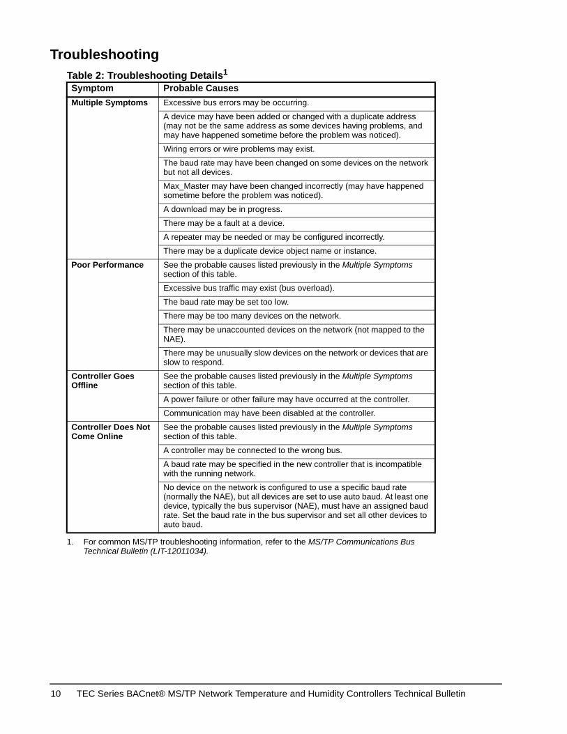
Troubleshooting
Table 2: Troubleshooting Details1
1. For common MS/TP troubleshooting information, refer to the MS/TP Communications Bus Technical Bulletin (LIT-12011034).
Symptom Probable CausesMultiple Symptoms Excessive bus errors may be occurring.
A device may have been added or changed with a duplicate address (may not be the same address as some devices having problems, and may have happened sometime before the problem was noticed).
Wiring errors or wire problems may exist.
The baud rate may have been changed on some devices on the network but not all devices.
Max_Master may have been changed incorrectly (may have happened sometime before the problem was noticed).
A download may be in progress.
There may be a fault at a device.
A repeater may be needed or may be configured incorrectly.
There may be a duplicate device object name or instance.
Poor Performance See the probable causes listed previously in the Multiple Symptoms section of this table.
Excessive bus traffic may exist (bus overload).
The baud rate may be set too low.
There may be too many devices on the network.
There may be unaccounted devices on the network (not mapped to the NAE).
There may be unusually slow devices on the network or devices that are slow to respond.
Controller Goes Offline
See the probable causes listed previously in the Multiple Symptoms section of this table.
A power failure or other failure may have occurred at the controller.
Communication may have been disabled at the controller.
Controller Does Not Come Online
See the probable causes listed previously in the Multiple Symptoms section of this table.
A controller may be connected to the wrong bus.
A baud rate may be specified in the new controller that is incompatible with the running network.
No device on the network is configured to use a specific baud rate (normally the NAE), but all devices are set to use auto baud. At least one device, typically the bus supervisor (NAE), must have an assigned baud rate. Set the baud rate in the bus supervisor and set all other devices to auto baud.
TEC Series BACnet® MS/TP Network Temperature and Humidity Controllers Technical Bulletin10
MS/TP Bus Objects Tables
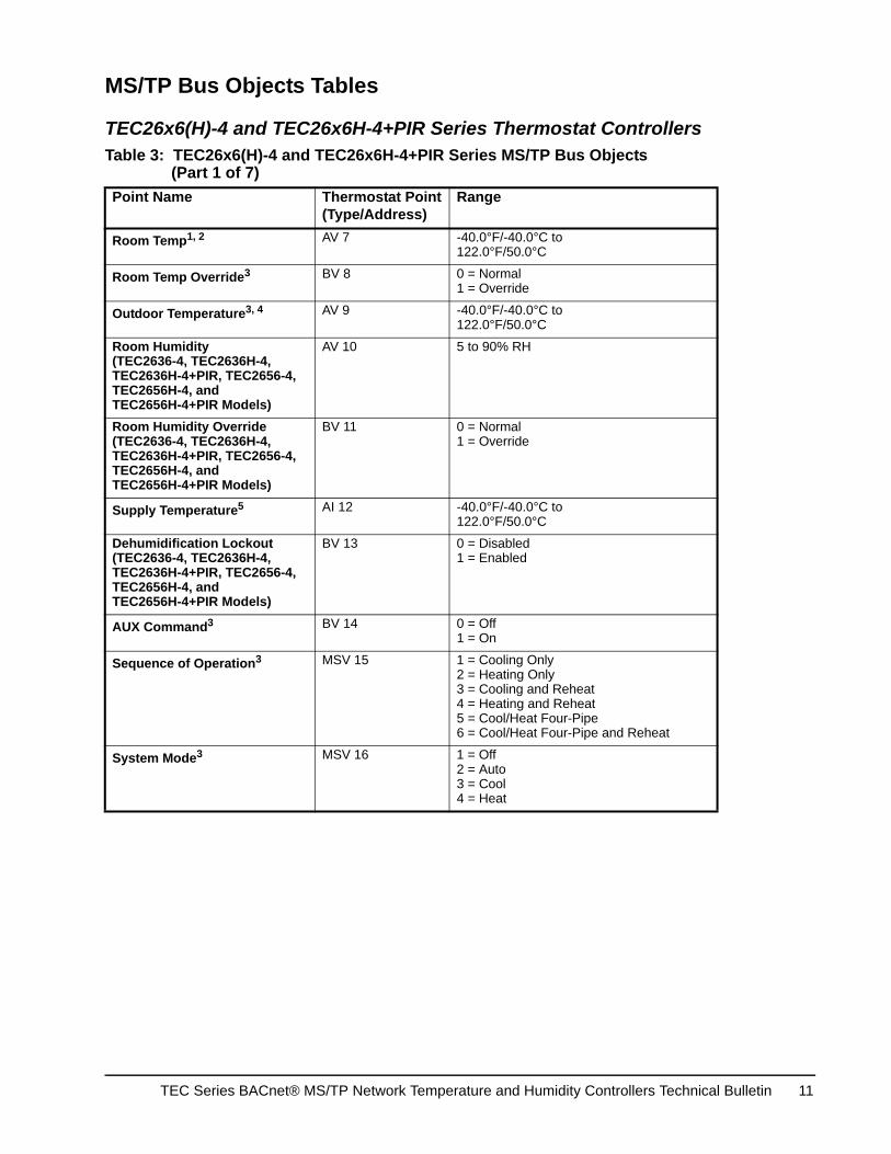
TEC26x6(H)-4 and TEC26x6H-4+PIR Series Thermostat Controllers
Table 3: TEC26x6(H)-4 and TEC26x6H-4+PIR Series MS/TP Bus Objects (Part 1 of 7)
Point Name Thermostat Point(Type/Address)
Range
Room Temp1, 2 AV 7 -40.0°F/-40.0°C to 122.0°F/50.0°C
Room Temp Override3 BV 8 0 = Normal1 = Override
Outdoor Temperature3, 4 AV 9 -40.0°F/-40.0°C to 122.0°F/50.0°C
Room Humidity(TEC2636-4, TEC2636H-4, TEC2636H-4+PIR, TEC2656-4, TEC2656H-4, and TEC2656H-4+PIR Models)
AV 10 5 to 90% RH
Room Humidity Override (TEC2636-4, TEC2636H-4, TEC2636H-4+PIR, TEC2656-4, TEC2656H-4, and TEC2656H-4+PIR Models)
BV 11 0 = Normal1 = Override
Supply Temperature5 AI 12 -40.0°F/-40.0°C to 122.0°F/50.0°C
Dehumidification Lockout (TEC2636-4, TEC2636H-4, TEC2636H-4+PIR, TEC2656-4, TEC2656H-4, and TEC2656H-4+PIR Models)
BV 13 0 = Disabled1 = Enabled
AUX Command3 BV 14 0 = Off1 = On
Sequence of Operation3 MSV 15 1 = Cooling Only2 = Heating Only3 = Cooling and Reheat4 = Heating and Reheat5 = Cool/Heat Four-Pipe6 = Cool/Heat Four-Pipe and Reheat
System Mode3 MSV 16 1 = Off2 = Auto3 = Cool4 = Heat
TEC Series BACnet® MS/TP Network Temperature and Humidity Controllers Technical Bulletin 11
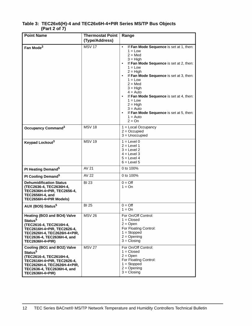
Fan Mode3 MSV 17 • If Fan Mode Sequence is set at 1, then:1 = Low2 = Med3 = High
• If Fan Mode Sequence is set at 2, then:1 = Low2 = High
• If Fan Mode Sequence is set at 3, then:1 = Low2 = Med3 = High4 = Auto
• If Fan Mode Sequence is set at 4, then:1 = Low2 = High3 = Auto
• If Fan Mode Sequence is set at 5, then:1 = Auto2 = On
Occupancy Command3 MSV 18 1 = Local Occupancy2 = Occupied3 = Unoccupied
Keypad Lockout3 MSV 19 1 = Level 02 = Level 13 = Level 24 = Level 35 = Level 46 = Level 5
PI Heating Demand5 AV 21 0 to 100%
PI Cooling Demand5 AV 22 0 to 100%
Dehumidification Status (TEC2636-4, TEC2636H-4, TEC2636H-4+PIR, TEC2656-4, TEC2656H-4, and TEC2656H-4+PIR Models)
BI 23 0 = Off1 = On
AUX (BO5) Status5 BI 25 0 = Off1 = On
Heating (BO3 and BO4) Valve Status5
(TEC2616-4, TEC2616H-4, TEC2616H-4+PIR, TEC2626-4, TEC2626H-4, TEC2626H-4+PIR, TEC2636-4, TEC2636H-4, and TEC2636H-4+PIR)
MSV 26 For On/Off Control:1 = Closed2 = OpenFor Floating Control:1 = Stopped2 = Opening3 = Closing
Cooling (BO1 and BO2) Valve Status5
(TEC2616-4, TEC2616H-4, TEC2616H-4+PIR, TEC2626-4, TEC2626H-4, TEC2626H-4+PIR, TEC2636-4, TEC2636H-4, and TEC2636H-4+PIR)
MSV 27 For On/Off Control:1 = Closed2 = OpenFor Floating Control:1 = Stopped2 = Opening3 = Closing
Table 3: TEC26x6(H)-4 and TEC26x6H-4+PIR Series MS/TP Bus Objects (Part 2 of 7)
Point Name Thermostat Point(Type/Address)
Range
TEC Series BACnet® MS/TP Network Temperature and Humidity Controllers Technical Bulletin12
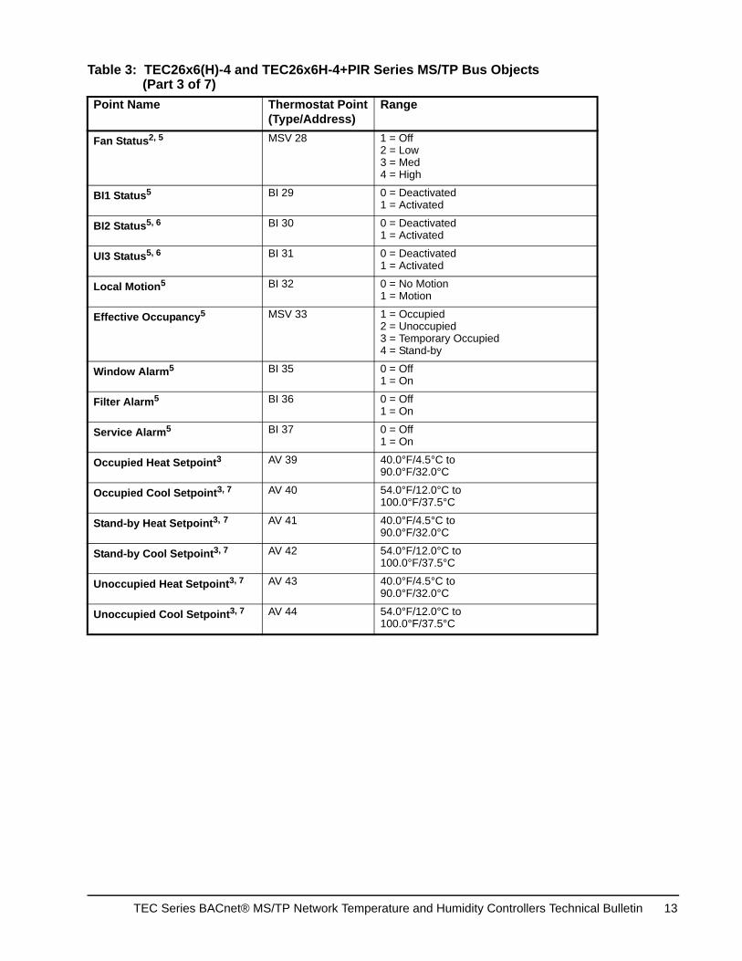
Fan Status2, 5 MSV 28 1 = Off2 = Low3 = Med4 = High
BI1 Status5 BI 29 0 = Deactivated1 = Activated
BI2 Status5, 6 BI 30 0 = Deactivated1 = Activated
UI3 Status5, 6 BI 31 0 = Deactivated1 = Activated
Local Motion5 BI 32 0 = No Motion1 = Motion
Effective Occupancy5 MSV 33 1 = Occupied2 = Unoccupied3 = Temporary Occupied4 = Stand-by
Window Alarm5 BI 35 0 = Off1 = On
Filter Alarm5 BI 36 0 = Off1 = On
Service Alarm5 BI 37 0 = Off1 = On
Occupied Heat Setpoint3 AV 39 40.0°F/4.5°C to90.0°F/32.0°C
Occupied Cool Setpoint3, 7 AV 40 54.0°F/12.0°C to100.0°F/37.5°C
Stand-by Heat Setpoint3, 7 AV 41 40.0°F/4.5°C to90.0°F/32.0°C
Stand-by Cool Setpoint3, 7 AV 42 54.0°F/12.0°C to100.0°F/37.5°C
Unoccupied Heat Setpoint3, 7 AV 43 40.0°F/4.5°C to90.0°F/32.0°C
Unoccupied Cool Setpoint3, 7 AV 44 54.0°F/12.0°C to100.0°F/37.5°C
Table 3: TEC26x6(H)-4 and TEC26x6H-4+PIR Series MS/TP Bus Objects (Part 3 of 7)
Point Name Thermostat Point(Type/Address)
Range
TEC Series BACnet® MS/TP Network Temperature and Humidity Controllers Technical Bulletin 13
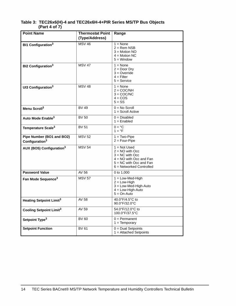
BI1 Configuration3 MSV 46 1 = None2 = Rem NSB3 = Motion NO4 = Motion NC5 = Window
BI2 Configuration3 MSV 47 1 = None2 = Door Dry3 = Override4 = Filter5 = Service
UI3 Configuration3 MSV 48 1 = None2 = COC/NH3 = COC/NC4 = COS5 = SS
Menu Scroll3 BV 49 0 = No Scroll1 = Scroll Active
Auto Mode Enable3 BV 50 0 = Disabled1 = Enabled
Temperature Scale3 BV 51 0 = °C1 = °F
Pipe Number (BO1 and BO2) Configuration3
MSV 52 1 = Two-Pipe2 = Four-Pipe
AUX (BO5) Configuration3 MSV 54 1 = Not Used2 = NO with Occ3 = NC with Occ4 = NO with Occ and Fan5 = NC with Occ and Fan6 = Networked Controlled
Password Value AV 56 0 to 1,000
Fan Mode Sequence3 MSV 57 1 = Low-Med-High2 = Low-High3 = Low-Med-High-Auto4 = Low-High-Auto5 = On-Auto
Heating Setpoint Limit3 AV 58 40.0°F/4.5°C to90.0°F/32.0°C
Cooling Setpoint Limit3 AV 59 54.0°F/12.0°C to100.0°F/37.5°C
Setpoint Type3 BV 60 0 = Permanent1 = Temporary
Setpoint Function BV 61 0 = Dual Setpoints1 = Attached Setpoints
Table 3: TEC26x6(H)-4 and TEC26x6H-4+PIR Series MS/TP Bus Objects (Part 4 of 7)
Point Name Thermostat Point(Type/Address)
Range
TEC Series BACnet® MS/TP Network Temperature and Humidity Controllers Technical Bulletin14
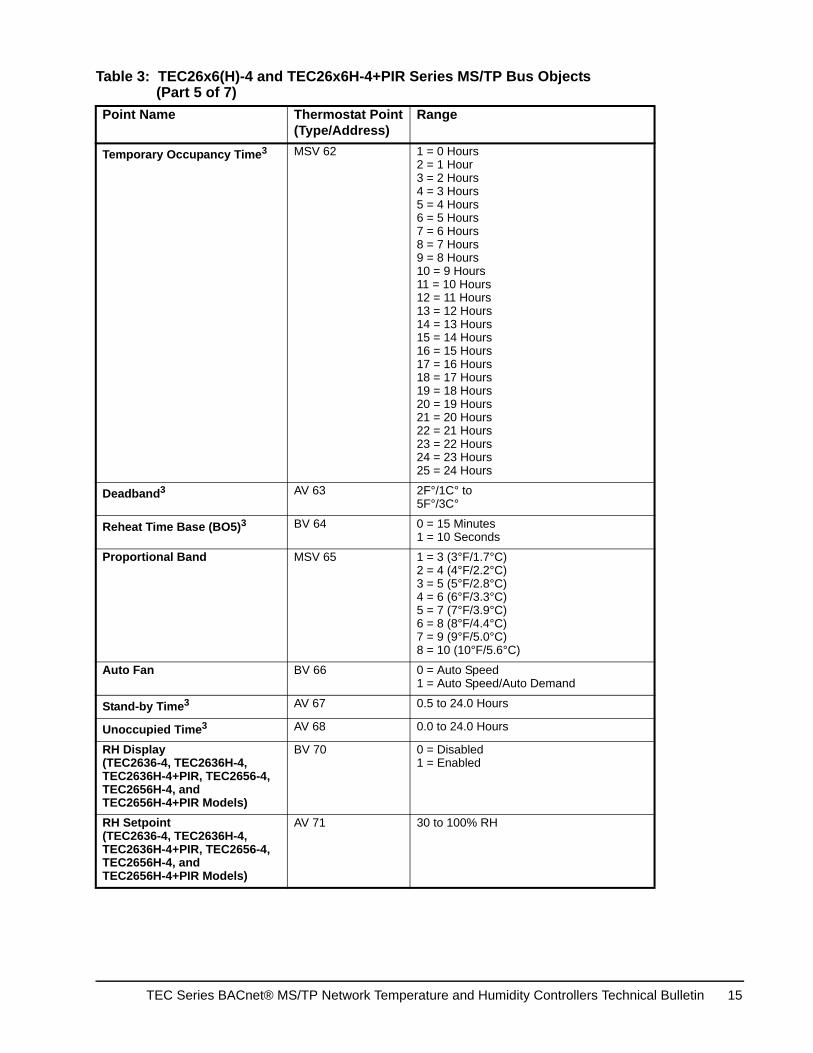
Temporary Occupancy Time3 MSV 62 1 = 0 Hours2 = 1 Hour3 = 2 Hours4 = 3 Hours5 = 4 Hours6 = 5 Hours7 = 6 Hours8 = 7 Hours9 = 8 Hours10 = 9 Hours11 = 10 Hours12 = 11 Hours13 = 12 Hours14 = 13 Hours15 = 14 Hours16 = 15 Hours17 = 16 Hours18 = 17 Hours19 = 18 Hours20 = 19 Hours21 = 20 Hours22 = 21 Hours23 = 22 Hours24 = 23 Hours25 = 24 Hours
Deadband3 AV 63 2F°/1C° to5F°/3C°
Reheat Time Base (BO5)3 BV 64 0 = 15 Minutes1 = 10 Seconds
Proportional Band MSV 65 1 = 3 (3°F/1.7°C)2 = 4 (4°F/2.2°C)3 = 5 (5°F/2.8°C)4 = 6 (6°F/3.3°C)5 = 7 (7°F/3.9°C)6 = 8 (8°F/4.4°C)7 = 9 (9°F/5.0°C)8 = 10 (10°F/5.6°C)
Auto Fan BV 66 0 = Auto Speed1 = Auto Speed/Auto Demand
Stand-by Time3 AV 67 0.5 to 24.0 Hours
Unoccupied Time3 AV 68 0.0 to 24.0 Hours
RH Display(TEC2636-4, TEC2636H-4, TEC2636H-4+PIR, TEC2656-4, TEC2656H-4, and TEC2656H-4+PIR Models)
BV 70 0 = Disabled1 = Enabled
RH Setpoint(TEC2636-4, TEC2636H-4, TEC2636H-4+PIR, TEC2656-4, TEC2656H-4, and TEC2656H-4+PIR Models)
AV 71 30 to 100% RH
Table 3: TEC26x6(H)-4 and TEC26x6H-4+PIR Series MS/TP Bus Objects (Part 5 of 7)
Point Name Thermostat Point(Type/Address)
Range
TEC Series BACnet® MS/TP Network Temperature and Humidity Controllers Technical Bulletin 15
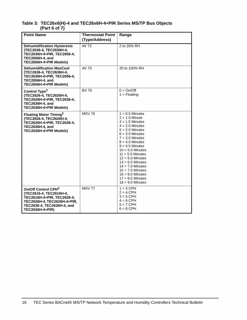
Dehumidification Hysteresis (TEC2636-4, TEC2636H-4, TEC2636H-4+PIR, TEC2656-4, TEC2656H-4, and TEC2656H-4+PIR Models)
AV 72 2 to 20% RH
Dehumidification MaxCool (TEC2636-4, TEC2636H-4, TEC2636H-4+PIR, TEC2656-4, TEC2656H-4, and TEC2656H-4+PIR Models)
AV 73 20 to 100% RH
Control Type3 (TEC2626-4, TEC2626H-4, TEC2626H-4+PIR, TEC2636-4, TEC2636H-4, and TEC2636H-4+PIR Models)
BV 75 0 = On/Off1 = Floating
Floating Motor Timing3 (TEC2626-4, TEC2626H-4, TEC2626H-4+PIR, TEC2636-4, TEC2636H-4, and TEC2636H-4+PIR Models)
MSV 76 1 = 0.5 Minutes2 = 1.0 Minute3 = 1.5 Minutes4 = 2.0 Minutes5 = 2.5 Minutes6 = 3.0 Minutes7 = 3.5 Minutes8 = 4.0 Minutes9 = 4.5 Minutes10 = 5.0 Minutes11 = 5.5 Minutes12 = 6.0 Minutes13 = 6.5 Minutes14 = 7.0 Minutes15 = 7.5 Minutes16 = 8.0 Minutes17 = 8.5 Minutes18 = 9.0 Minutes
On/Off Control CPH3
(TEC2616-4, TEC2616H-4, TEC2616H-4+PIR, TEC2626-4, TEC2626H-4, TEC2626H-4+PIR, TEC2636-4, TEC2636H-4, and TEC2636H-4+PIR)
MSV 77 1 = 3 CPH2 = 4 CPH3 = 5 CPH4 = 6 CPH5 = 7 CPH6 = 8 CPH
Table 3: TEC26x6(H)-4 and TEC26x6H-4+PIR Series MS/TP Bus Objects (Part 6 of 7)
Point Name Thermostat Point(Type/Address)
Range
TEC Series BACnet® MS/TP Network Temperature and Humidity Controllers Technical Bulletin16
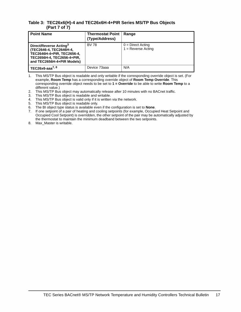
Direct/Reverse Acting3 (TEC2646-4, TEC2646H-4, TEC2646H-4+PIR, TEC2656-4, TEC2656H-4, TEC2656-4+PIR, and TEC2656H-4+PIR Models)
BV 78 0 = Direct Acting1 = Reverse Acting
TEC26x6-aaa7, 8 Device 73aaa N/A
1. This MS/TP Bus object is readable and only writable if the corresponding override object is set. (For example, Room Temp has a corresponding override object of Room Temp Override. This corresponding override object needs to be set to 1 = Override to be able to write Room Temp to a different value.)
2. This MS/TP Bus object may automatically release after 10 minutes with no BACnet traffic.3. This MS/TP Bus object is readable and writable.4. This MS/TP Bus object is valid only if it is written via the network.5. This MS/TP Bus object is readable only.6. The BI object type status is available even if the configuration is set to None.7. If one setpoint of a pair of heating and cooling setpoints (for example, Occupied Heat Setpoint and
Occupied Cool Setpoint) is overridden, the other setpoint of the pair may be automatically adjusted by the thermostat to maintain the minimum deadband between the two setpoints.
8. Max_Master is writable.
Table 3: TEC26x6(H)-4 and TEC26x6H-4+PIR Series MS/TP Bus Objects (Part 7 of 7)
Point Name Thermostat Point(Type/Address)
Range
TEC Series BACnet® MS/TP Network Temperature and Humidity Controllers Technical Bulletin 17
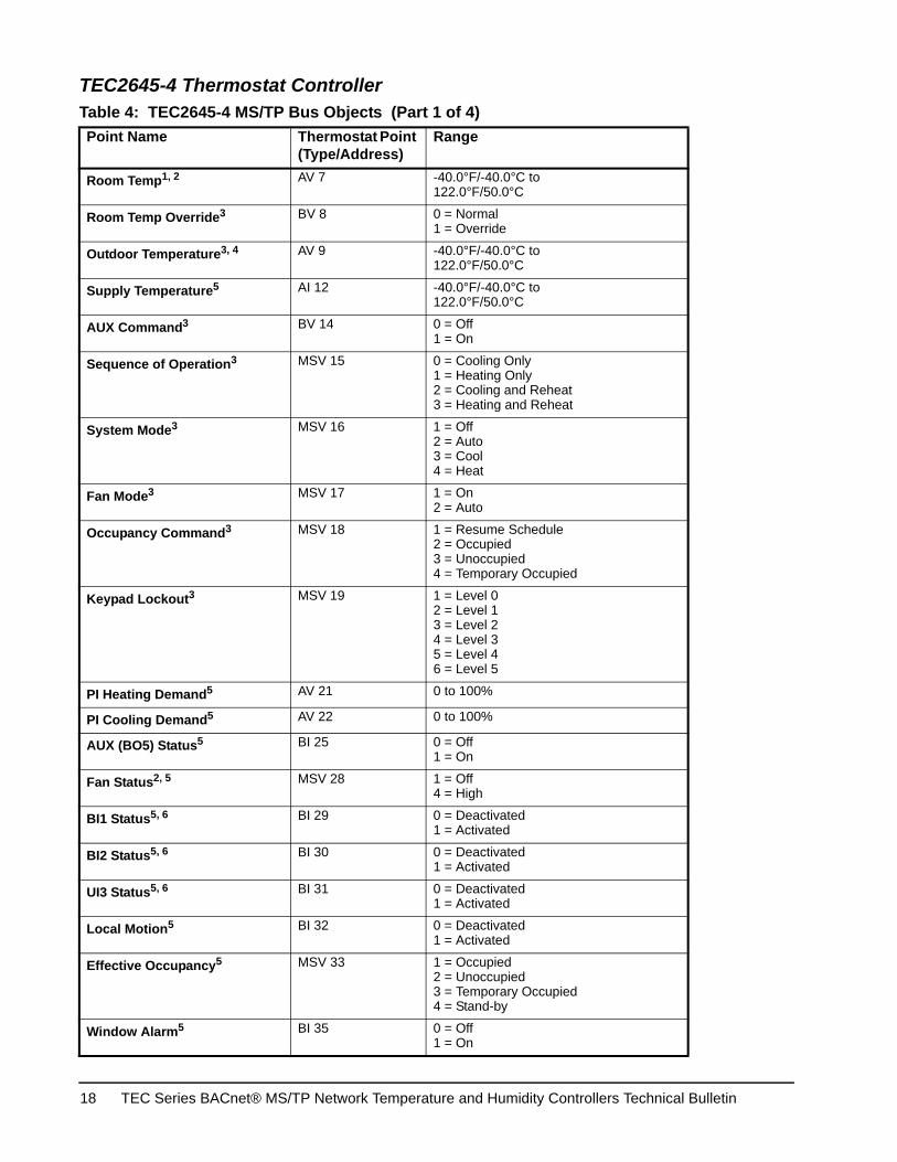
TEC2645-4 Thermostat Controller Table 4: TEC2645-4 MS/TP Bus Objects (Part 1 of 4)Point Name Thermostat Point
(Type/Address)Range
Room Temp1, 2 AV 7 -40.0°F/-40.0°C to 122.0°F/50.0°C
Room Temp Override3 BV 8 0 = Normal1 = Override
Outdoor Temperature3, 4 AV 9 -40.0°F/-40.0°C to 122.0°F/50.0°C
Supply Temperature5 AI 12 -40.0°F/-40.0°C to 122.0°F/50.0°C
AUX Command3 BV 14 0 = Off1 = On
Sequence of Operation3 MSV 15 0 = Cooling Only1 = Heating Only2 = Cooling and Reheat3 = Heating and Reheat
System Mode3 MSV 16 1 = Off2 = Auto3 = Cool4 = Heat
Fan Mode3 MSV 17 1 = On2 = Auto
Occupancy Command3 MSV 18 1 = Resume Schedule2 = Occupied3 = Unoccupied4 = Temporary Occupied
Keypad Lockout3 MSV 19 1 = Level 02 = Level 13 = Level 24 = Level 35 = Level 46 = Level 5
PI Heating Demand5 AV 21 0 to 100%
PI Cooling Demand5 AV 22 0 to 100%
AUX (BO5) Status5 BI 25 0 = Off1 = On
Fan Status2, 5 MSV 28 1 = Off4 = High
BI1 Status5, 6 BI 29 0 = Deactivated1 = Activated
BI2 Status5, 6 BI 30 0 = Deactivated1 = Activated
UI3 Status5, 6 BI 31 0 = Deactivated1 = Activated
Local Motion5 BI 32 0 = Deactivated1 = Activated
Effective Occupancy5 MSV 33 1 = Occupied2 = Unoccupied3 = Temporary Occupied4 = Stand-by
Window Alarm5 BI 35 0 = Off1 = On
TEC Series BACnet® MS/TP Network Temperature and Humidity Controllers Technical Bulletin18
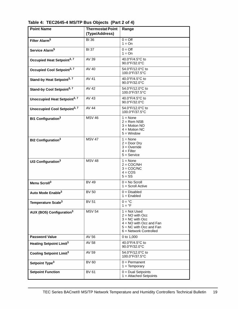
Filter Alarm5 BI 36 0 = Off1 = On
Service Alarm5 BI 37 0 = Off1 = On
Occupied Heat Setpoint3, 7 AV 39 40.0°F/4.5°C to90.0°F/32.0°C
Occupied Cool Setpoint3, 7 AV 40 54.0°F/12.0°C to100.0°F/37.5°C
Stand-by Heat Setpoint3, 7 AV 41 40.0°F/4.5°C to90.0°F/32.0°C
Stand-by Cool Setpoint3, 7 AV 42 54.0°F/12.0°C to100.0°F/37.5°C
Unoccupied Heat Setpoint3, 7 AV 43 40.0°F/4.5°C to90.0°F/32.0°C
Unoccupied Cool Setpoint3, 7 AV 44 54.0°F/12.0°C to100.0°F/37.5°C
BI1 Configuration3 MSV 46 1 = None2 = Rem NSB3 = Motion NO4 = Motion NC5 = Window
BI2 Configuration3 MSV 47 1 = None2 = Door Dry3 = Override4 = Filter5 = Service
UI3 Configuration3 MSV 48 1 = None2 = COC/NH3 = COC/NC4 = COS5 = SS
Menu Scroll3 BV 49 0 = No Scroll1 = Scroll Active
Auto Mode Enable3 BV 50 0 = Disabled1 = Enabled
Temperature Scale3 BV 51 0 = °C1 = °F
AUX (BO5) Configuration3 MSV 54 1 = Not Used2 = NO with Occ3 = NC with Occ4 = NO with Occ and Fan 5 = NC with Occ and Fan 6 = Network Controlled
Password Value AV 56 0 to 1,000
Heating Setpoint Limit3 AV 58 40.0°F/4.5°C to90.0°F/32.0°C
Cooling Setpoint Limit3 AV 59 54.0°F/12.0°C to100.0°F/37.5°C
Setpoint Type3 BV 60 0 = Permanent1 = Temporary
Setpoint Function BV 61 0 = Dual Setpoints1 = Attached Setpoints
Table 4: TEC2645-4 MS/TP Bus Objects (Part 2 of 4)Point Name Thermostat Point
(Type/Address)Range
TEC Series BACnet® MS/TP Network Temperature and Humidity Controllers Technical Bulletin 19

Temporary Occupancy Time3 MSV 62 1 = 0 Hours2 = 1 Hour3 = 2 Hours4 = 3 Hours5 = 4 Hours6 = 5 Hours7 = 6 Hours8 = 7 Hours9 = 8 Hours10 = 9 Hours11 = 10 Hours12 = 11 Hours13 = 12 Hours14 = 13 Hours15 = 14 Hours16 = 15 Hours17 = 16 Hours18 = 17 Hours19 = 18 Hours20 = 19 Hours21 = 20 Hours22 = 21 Hours23 = 22 Hours24 = 23 Hours25 = 24 Hours
Deadband3 AV 63 2F°/1C° to5F°/3C°
Reheat Time Base (BO5)3 BV 64 0 = 15 Minutes1 = 10 Seconds
Proportional Band MSV 65 1 = 3 (3°F/1.7°C)2 = 4 (4°F/2.2°C)3 = 5 (5°F/2.8°C)4 = 6 (6°F/3.3°C)5 = 7 (7°F/3.9°C)6 = 8 (8°F/4.4°C)7 = 9 (9°F/5.0°C)8 = 10 (10°F/5.6°C)
Stand-by Time3 AV 67 0.5 Hours to24.0 Hours
Unoccupied Time3 AV 68 0.0 Hours to24.0 Hours
Direct/Reverse Acting3 BV 78 0 = Direct Acting1 = Reverse Acting
Table 4: TEC2645-4 MS/TP Bus Objects (Part 3 of 4)Point Name Thermostat Point
(Type/Address)Range
TEC Series BACnet® MS/TP Network Temperature and Humidity Controllers Technical Bulletin20
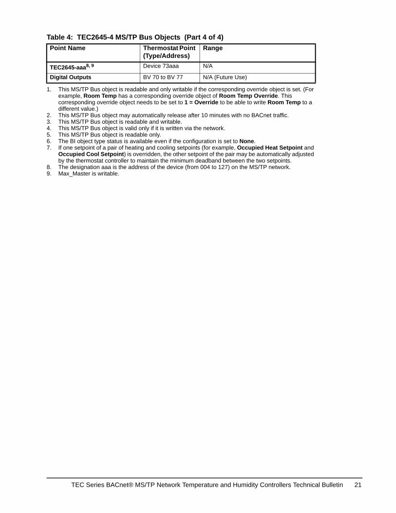
TEC2645-aaa8, 9 Device 73aaa N/A
Digital Outputs BV 70 to BV 77 N/A (Future Use)
1. This MS/TP Bus object is readable and only writable if the corresponding override object is set. (For example, Room Temp has a corresponding override object of Room Temp Override. This corresponding override object needs to be set to 1 = Override to be able to write Room Temp to a different value.)
2. This MS/TP Bus object may automatically release after 10 minutes with no BACnet traffic.3. This MS/TP Bus object is readable and writable.4. This MS/TP Bus object is valid only if it is written via the network.5. This MS/TP Bus object is readable only.6. The BI object type status is available even if the configuration is set to None.7. If one setpoint of a pair of heating and cooling setpoints (for example, Occupied Heat Setpoint and
Occupied Cool Setpoint) is overridden, the other setpoint of the pair may be automatically adjusted by the thermostat controller to maintain the minimum deadband between the two setpoints.
8. The designation aaa is the address of the device (from 004 to 127) on the MS/TP network.9. Max_Master is writable.
Table 4: TEC2645-4 MS/TP Bus Objects (Part 4 of 4)Point Name Thermostat Point
(Type/Address)Range
TEC Series BACnet® MS/TP Network Temperature and Humidity Controllers Technical Bulletin 21
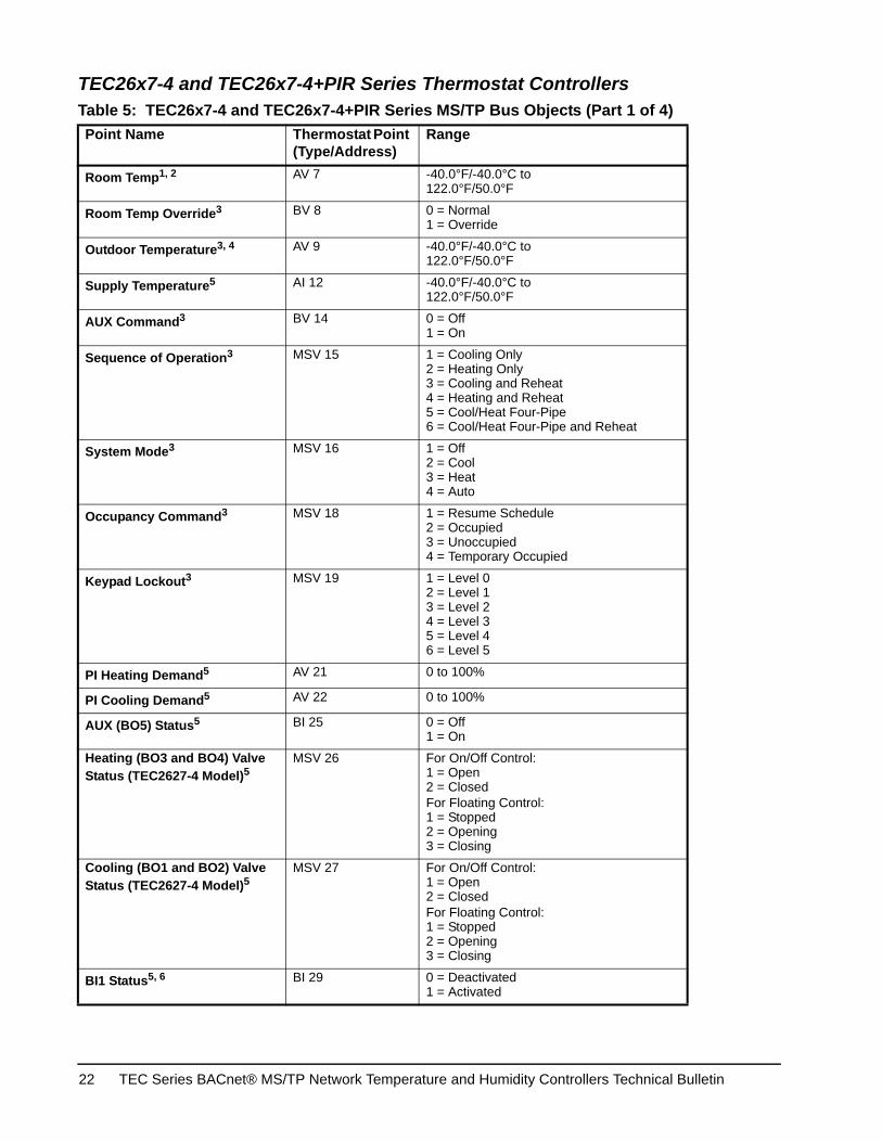
TEC26x7-4 and TEC26x7-4+PIR Series Thermostat Controllers
Table 5: TEC26x7-4 and TEC26x7-4+PIR Series MS/TP Bus Objects (Part 1 of 4)Point Name Thermostat Point
(Type/Address)Range
Room Temp1, 2 AV 7 -40.0°F/-40.0°C to122.0°F/50.0°F
Room Temp Override3 BV 8 0 = Normal1 = Override
Outdoor Temperature3, 4 AV 9 -40.0°F/-40.0°C to122.0°F/50.0°F
Supply Temperature5 AI 12 -40.0°F/-40.0°C to122.0°F/50.0°F
AUX Command3 BV 14 0 = Off1 = On
Sequence of Operation3 MSV 15 1 = Cooling Only2 = Heating Only3 = Cooling and Reheat4 = Heating and Reheat5 = Cool/Heat Four-Pipe6 = Cool/Heat Four-Pipe and Reheat
System Mode3 MSV 16 1 = Off2 = Cool3 = Heat4 = Auto
Occupancy Command3 MSV 18 1 = Resume Schedule2 = Occupied3 = Unoccupied4 = Temporary Occupied
Keypad Lockout3 MSV 19 1 = Level 02 = Level 13 = Level 24 = Level 35 = Level 46 = Level 5
PI Heating Demand5 AV 21 0 to 100%
PI Cooling Demand5 AV 22 0 to 100%
AUX (BO5) Status5 BI 25 0 = Off1 = On
Heating (BO3 and BO4) Valve Status (TEC2627-4 Model)5
MSV 26 For On/Off Control:1 = Open2 = ClosedFor Floating Control:1 = Stopped2 = Opening3 = Closing
Cooling (BO1 and BO2) Valve Status (TEC2627-4 Model)5
MSV 27 For On/Off Control:1 = Open2 = ClosedFor Floating Control:1 = Stopped2 = Opening3 = Closing
BI1 Status5, 6 BI 29 0 = Deactivated1 = Activated
TEC Series BACnet® MS/TP Network Temperature and Humidity Controllers Technical Bulletin22
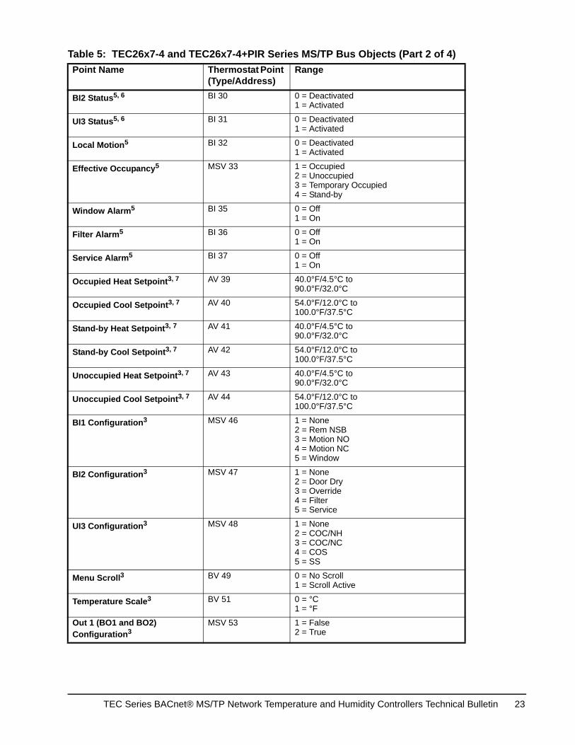
BI2 Status5, 6 BI 30 0 = Deactivated1 = Activated
UI3 Status5, 6 BI 31 0 = Deactivated1 = Activated
Local Motion5 BI 32 0 = Deactivated1 = Activated
Effective Occupancy5 MSV 33 1 = Occupied2 = Unoccupied3 = Temporary Occupied4 = Stand-by
Window Alarm5 BI 35 0 = Off1 = On
Filter Alarm5 BI 36 0 = Off1 = On
Service Alarm5 BI 37 0 = Off1 = On
Occupied Heat Setpoint3, 7 AV 39 40.0°F/4.5°C to90.0°F/32.0°C
Occupied Cool Setpoint3, 7 AV 40 54.0°F/12.0°C to100.0°F/37.5°C
Stand-by Heat Setpoint3, 7 AV 41 40.0°F/4.5°C to90.0°F/32.0°C
Stand-by Cool Setpoint3, 7 AV 42 54.0°F/12.0°C to100.0°F/37.5°C
Unoccupied Heat Setpoint3, 7 AV 43 40.0°F/4.5°C to90.0°F/32.0°C
Unoccupied Cool Setpoint3, 7 AV 44 54.0°F/12.0°C to100.0°F/37.5°C
BI1 Configuration3 MSV 46 1 = None2 = Rem NSB3 = Motion NO4 = Motion NC5 = Window
BI2 Configuration3 MSV 47 1 = None2 = Door Dry3 = Override4 = Filter5 = Service
UI3 Configuration3 MSV 48 1 = None2 = COC/NH3 = COC/NC4 = COS5 = SS
Menu Scroll3 BV 49 0 = No Scroll1 = Scroll Active
Temperature Scale3 BV 51 0 = °C1 = °F
Out 1 (BO1 and BO2) Configuration3
MSV 53 1 = False2 = True
Table 5: TEC26x7-4 and TEC26x7-4+PIR Series MS/TP Bus Objects (Part 2 of 4)Point Name Thermostat Point
(Type/Address)Range
TEC Series BACnet® MS/TP Network Temperature and Humidity Controllers Technical Bulletin 23
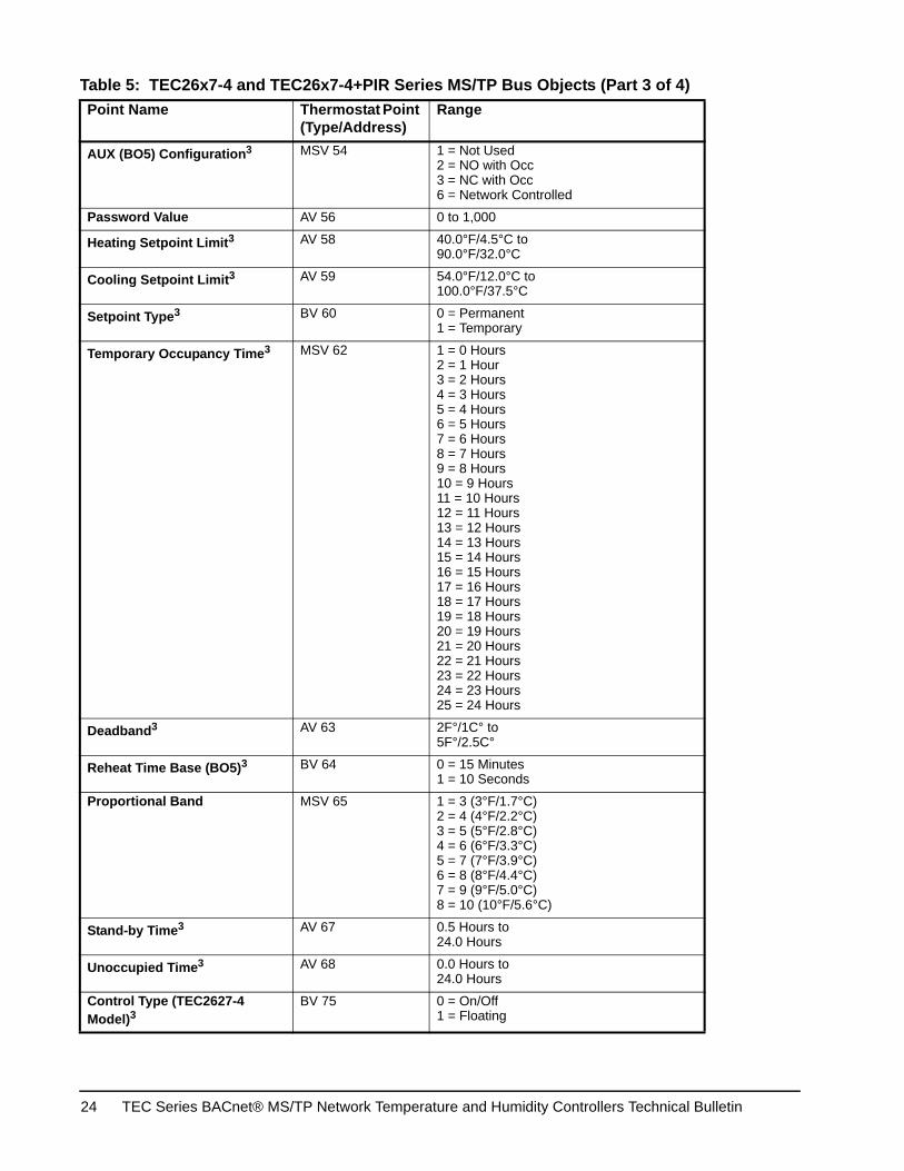
AUX (BO5) Configuration3 MSV 54 1 = Not Used2 = NO with Occ3 = NC with Occ6 = Network Controlled
Password Value AV 56 0 to 1,000
Heating Setpoint Limit3 AV 58 40.0°F/4.5°C to90.0°F/32.0°C
Cooling Setpoint Limit3 AV 59 54.0°F/12.0°C to100.0°F/37.5°C
Setpoint Type3 BV 60 0 = Permanent1 = Temporary
Temporary Occupancy Time3 MSV 62 1 = 0 Hours2 = 1 Hour3 = 2 Hours4 = 3 Hours5 = 4 Hours6 = 5 Hours7 = 6 Hours8 = 7 Hours9 = 8 Hours10 = 9 Hours11 = 10 Hours12 = 11 Hours13 = 12 Hours14 = 13 Hours15 = 14 Hours16 = 15 Hours17 = 16 Hours18 = 17 Hours19 = 18 Hours20 = 19 Hours21 = 20 Hours22 = 21 Hours23 = 22 Hours24 = 23 Hours25 = 24 Hours
Deadband3 AV 63 2F°/1C° to5F°/2.5C°
Reheat Time Base (BO5)3 BV 64 0 = 15 Minutes1 = 10 Seconds
Proportional Band MSV 65 1 = 3 (3°F/1.7°C)2 = 4 (4°F/2.2°C)3 = 5 (5°F/2.8°C)4 = 6 (6°F/3.3°C)5 = 7 (7°F/3.9°C)6 = 8 (8°F/4.4°C)7 = 9 (9°F/5.0°C)8 = 10 (10°F/5.6°C)
Stand-by Time3 AV 67 0.5 Hours to24.0 Hours
Unoccupied Time3 AV 68 0.0 Hours to24.0 Hours
Control Type (TEC2627-4 Model)3
BV 75 0 = On/Off1 = Floating
Table 5: TEC26x7-4 and TEC26x7-4+PIR Series MS/TP Bus Objects (Part 3 of 4)Point Name Thermostat Point
(Type/Address)Range
TEC Series BACnet® MS/TP Network Temperature and Humidity Controllers Technical Bulletin24
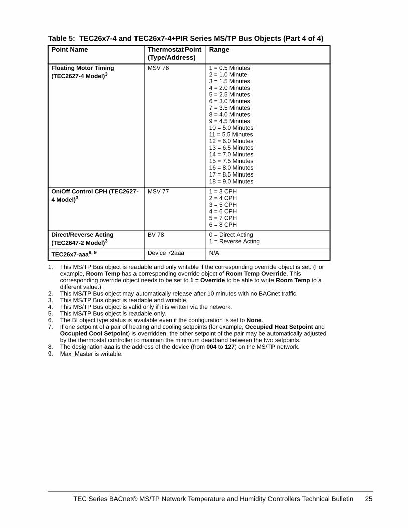
Floating Motor Timing (TEC2627-4 Model)3
MSV 76 1 = 0.5 Minutes2 = 1.0 Minute3 = 1.5 Minutes4 = 2.0 Minutes5 = 2.5 Minutes6 = 3.0 Minutes7 = 3.5 Minutes8 = 4.0 Minutes9 = 4.5 Minutes10 = 5.0 Minutes11 = 5.5 Minutes12 = 6.0 Minutes13 = 6.5 Minutes14 = 7.0 Minutes15 = 7.5 Minutes16 = 8.0 Minutes17 = 8.5 Minutes18 = 9.0 Minutes
On/Off Control CPH (TEC2627-4 Model)3
MSV 77 1 = 3 CPH2 = 4 CPH3 = 5 CPH4 = 6 CPH5 = 7 CPH6 = 8 CPH
Direct/Reverse Acting (TEC2647-2 Model)3
BV 78 0 = Direct Acting1 = Reverse Acting
TEC26x7-aaa8, 9 Device 72aaa N/A
1. This MS/TP Bus object is readable and only writable if the corresponding override object is set. (For example, Room Temp has a corresponding override object of Room Temp Override. This corresponding override object needs to be set to 1 = Override to be able to write Room Temp to a different value.)
2. This MS/TP Bus object may automatically release after 10 minutes with no BACnet traffic.3. This MS/TP Bus object is readable and writable.4. This MS/TP Bus object is valid only if it is written via the network.5. This MS/TP Bus object is readable only.6. The BI object type status is available even if the configuration is set to None.7. If one setpoint of a pair of heating and cooling setpoints (for example, Occupied Heat Setpoint and
Occupied Cool Setpoint) is overridden, the other setpoint of the pair may be automatically adjusted by the thermostat controller to maintain the minimum deadband between the two setpoints.
8. The designation aaa is the address of the device (from 004 to 127) on the MS/TP network.9. Max_Master is writable.
Table 5: TEC26x7-4 and TEC26x7-4+PIR Series MS/TP Bus Objects (Part 4 of 4)Point Name Thermostat Point
(Type/Address)Range
TEC Series BACnet® MS/TP Network Temperature and Humidity Controllers Technical Bulletin 25
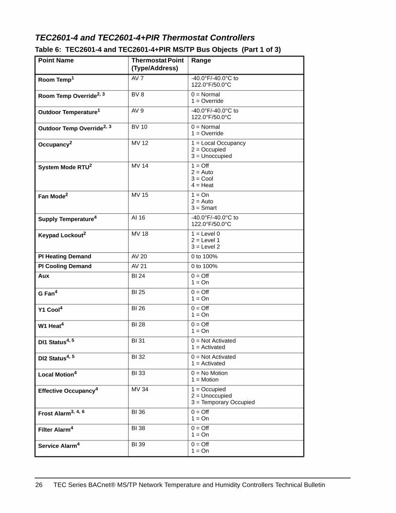
TEC2601-4 and TEC2601-4+PIR Thermostat Controllers Table 6: TEC2601-4 and TEC2601-4+PIR MS/TP Bus Objects (Part 1 of 3)Point Name Thermostat Point
(Type/Address)Range
Room Temp1 AV 7 -40.0°F/-40.0°C to122.0°F/50.0°C
Room Temp Override2, 3 BV 8 0 = Normal1 = Override
Outdoor Temperature1 AV 9 -40.0°F/-40.0°C to122.0°F/50.0°C
Outdoor Temp Override2, 3 BV 10 0 = Normal1 = Override
Occupancy2 MV 12 1 = Local Occupancy2 = Occupied3 = Unoccupied
System Mode RTU2 MV 14 1 = Off2 = Auto3 = Cool4 = Heat
Fan Mode2 MV 15 1 = On2 = Auto3 = Smart
Supply Temperature4 AI 16 -40.0°F/-40.0°C to122.0°F/50.0°C
Keypad Lockout2 MV 18 1 = Level 02 = Level 13 = Level 2
PI Heating Demand AV 20 0 to 100%
PI Cooling Demand AV 21 0 to 100%
Aux BI 24 0 = Off1 = On
G Fan4 BI 25 0 = Off1 = On
Y1 Cool4 BI 26 0 = Off1 = On
W1 Heat4 BI 28 0 = Off1 = On
DI1 Status4, 5 BI 31 0 = Not Activated1 = Activated
DI2 Status4, 5 BI 32 0 = Not Activated1 = Activated
Local Motion4 BI 33 0 = No Motion1 = Motion
Effective Occupancy4 MV 34 1 = Occupied2 = Unoccupied3 = Temporary Occupied
Frost Alarm3, 4, 6 BI 36 0 = Off1 = On
Filter Alarm4 BI 38 0 = Off1 = On
Service Alarm4 BI 39 0 = Off1 = On
TEC Series BACnet® MS/TP Network Temperature and Humidity Controllers Technical Bulletin26
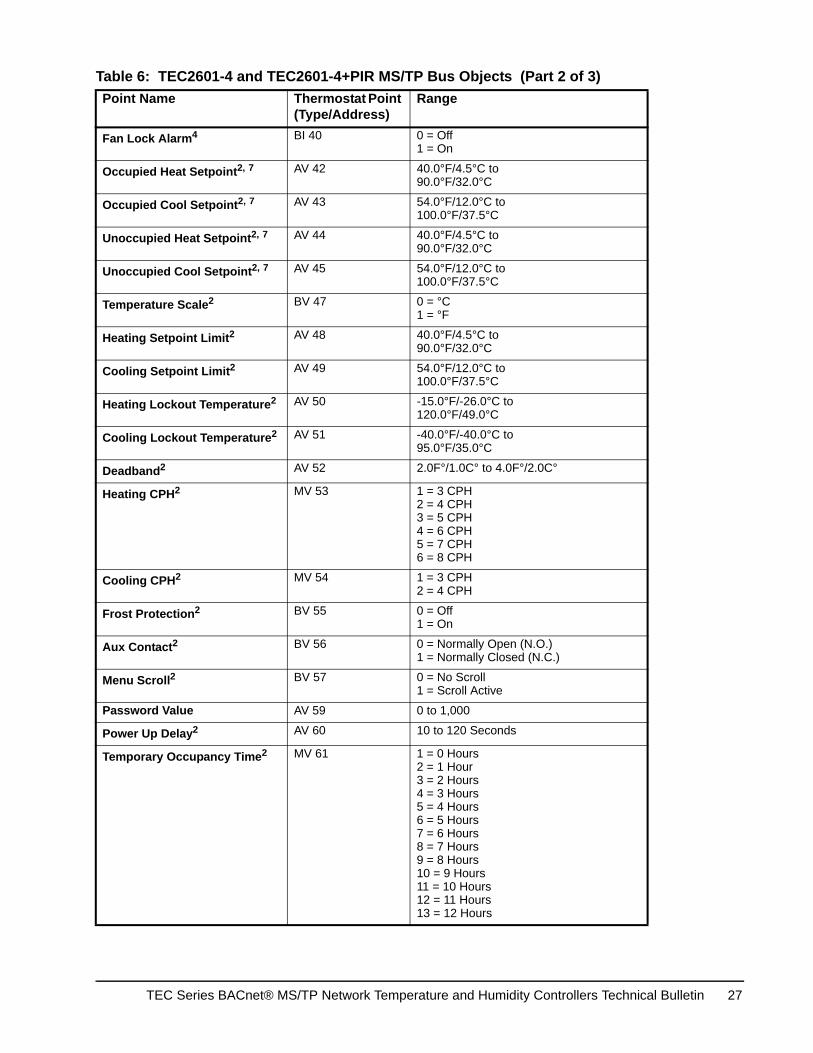
Fan Lock Alarm4 BI 40 0 = Off1 = On
Occupied Heat Setpoint2, 7 AV 42 40.0°F/4.5°C to90.0°F/32.0°C
Occupied Cool Setpoint2, 7 AV 43 54.0°F/12.0°C to100.0°F/37.5°C
Unoccupied Heat Setpoint2, 7 AV 44 40.0°F/4.5°C to90.0°F/32.0°C
Unoccupied Cool Setpoint2, 7 AV 45 54.0°F/12.0°C to100.0°F/37.5°C
Temperature Scale2 BV 47 0 = °C1 = °F
Heating Setpoint Limit2 AV 48 40.0°F/4.5°C to90.0°F/32.0°C
Cooling Setpoint Limit2 AV 49 54.0°F/12.0°C to100.0°F/37.5°C
Heating Lockout Temperature2 AV 50 -15.0°F/-26.0°C to120.0°F/49.0°C
Cooling Lockout Temperature2 AV 51 -40.0°F/-40.0°C to95.0°F/35.0°C
Deadband2 AV 52 2.0F°/1.0C° to 4.0F°/2.0C°
Heating CPH2 MV 53 1 = 3 CPH2 = 4 CPH3 = 5 CPH4 = 6 CPH5 = 7 CPH6 = 8 CPH
Cooling CPH2 MV 54 1 = 3 CPH2 = 4 CPH
Frost Protection2 BV 55 0 = Off1 = On
Aux Contact2 BV 56 0 = Normally Open (N.O.)1 = Normally Closed (N.C.)
Menu Scroll2 BV 57 0 = No Scroll1 = Scroll Active
Password Value AV 59 0 to 1,000
Power Up Delay2 AV 60 10 to 120 Seconds
Temporary Occupancy Time2 MV 61 1 = 0 Hours2 = 1 Hour3 = 2 Hours4 = 3 Hours5 = 4 Hours6 = 5 Hours7 = 6 Hours8 = 7 Hours9 = 8 Hours10 = 9 Hours 11 = 10 Hours12 = 11 Hours13 = 12 Hours
Table 6: TEC2601-4 and TEC2601-4+PIR MS/TP Bus Objects (Part 2 of 3)Point Name Thermostat Point
(Type/Address)Range
TEC Series BACnet® MS/TP Network Temperature and Humidity Controllers Technical Bulletin 27
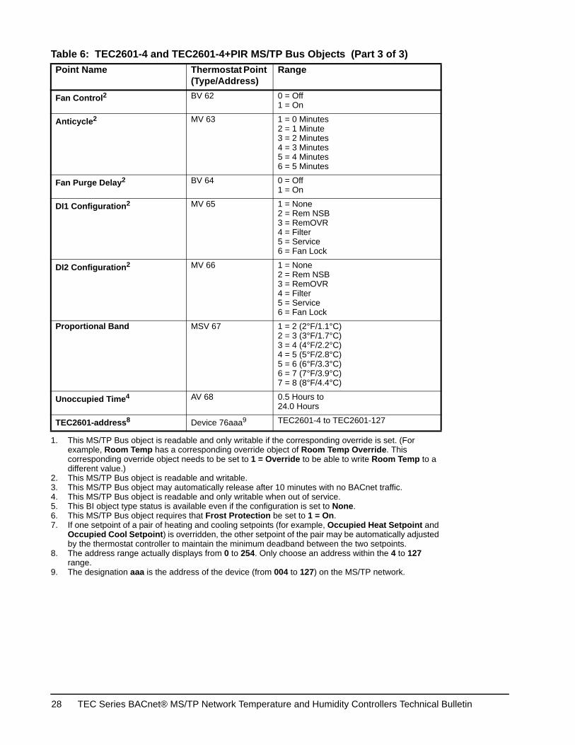
Fan Control2 BV 62 0 = Off1 = On
Anticycle2 MV 63 1 = 0 Minutes2 = 1 Minute3 = 2 Minutes4 = 3 Minutes5 = 4 Minutes6 = 5 Minutes
Fan Purge Delay2 BV 64 0 = Off1 = On
DI1 Configuration2 MV 65 1 = None2 = Rem NSB3 = RemOVR4 = Filter5 = Service6 = Fan Lock
DI2 Configuration2 MV 66 1 = None2 = Rem NSB3 = RemOVR4 = Filter5 = Service6 = Fan Lock
Proportional Band MSV 67 1 = 2 (2°F/1.1°C)2 = 3 (3°F/1.7°C)3 = 4 (4°F/2.2°C)4 = 5 (5°F/2.8°C)5 = 6 (6°F/3.3°C)6 = 7 (7°F/3.9°C)7 = 8 (8°F/4.4°C)
Unoccupied Time4 AV 68 0.5 Hours to24.0 Hours
TEC2601-address8 Device 76aaa9 TEC2601-4 to TEC2601-127
1. This MS/TP Bus object is readable and only writable if the corresponding override is set. (For example, Room Temp has a corresponding override object of Room Temp Override. This corresponding override object needs to be set to 1 = Override to be able to write Room Temp to a different value.)
2. This MS/TP Bus object is readable and writable.3. This MS/TP Bus object may automatically release after 10 minutes with no BACnet traffic.4. This MS/TP Bus object is readable and only writable when out of service.5. This BI object type status is available even if the configuration is set to None.6. This MS/TP Bus object requires that Frost Protection be set to 1 = On.7. If one setpoint of a pair of heating and cooling setpoints (for example, Occupied Heat Setpoint and
Occupied Cool Setpoint) is overridden, the other setpoint of the pair may be automatically adjusted by the thermostat controller to maintain the minimum deadband between the two setpoints.
8. The address range actually displays from 0 to 254. Only choose an address within the 4 to 127 range.
9. The designation aaa is the address of the device (from 004 to 127) on the MS/TP network.
Table 6: TEC2601-4 and TEC2601-4+PIR MS/TP Bus Objects (Part 3 of 3)Point Name Thermostat Point
(Type/Address)Range
TEC Series BACnet® MS/TP Network Temperature and Humidity Controllers Technical Bulletin28
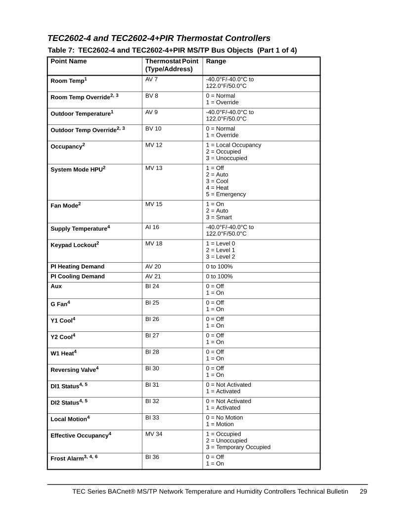
TEC2602-4 and TEC2602-4+PIR Thermostat Controllers Table 7: TEC2602-4 and TEC2602-4+PIR MS/TP Bus Objects (Part 1 of 4)Point Name Thermostat Point
(Type/Address)Range
Room Temp1 AV 7 -40.0°F/-40.0°C to122.0°F/50.0°C
Room Temp Override2, 3 BV 8 0 = Normal1 = Override
Outdoor Temperature1 AV 9 -40.0°F/-40.0°C to122.0°F/50.0°C
Outdoor Temp Override2, 3 BV 10 0 = Normal1 = Override
Occupancy2 MV 12 1 = Local Occupancy2 = Occupied3 = Unoccupied
System Mode HPU2 MV 13 1 = Off2 = Auto3 = Cool4 = Heat5 = Emergency
Fan Mode2 MV 15 1 = On2 = Auto3 = Smart
Supply Temperature4 AI 16 -40.0°F/-40.0°C to122.0°F/50.0°C
Keypad Lockout2 MV 18 1 = Level 02 = Level 13 = Level 2
PI Heating Demand AV 20 0 to 100%
PI Cooling Demand AV 21 0 to 100%
Aux BI 24 0 = Off1 = On
G Fan4 BI 25 0 = Off1 = On
Y1 Cool4 BI 26 0 = Off1 = On
Y2 Cool4 BI 27 0 = Off1 = On
W1 Heat4 BI 28 0 = Off1 = On
Reversing Valve4 BI 30 0 = Off1 = On
DI1 Status4, 5 BI 31 0 = Not Activated1 = Activated
DI2 Status4, 5 BI 32 0 = Not Activated1 = Activated
Local Motion4 BI 33 0 = No Motion1 = Motion
Effective Occupancy4 MV 34 1 = Occupied2 = Unoccupied3 = Temporary Occupied
Frost Alarm3, 4, 6 BI 36 0 = Off1 = On
TEC Series BACnet® MS/TP Network Temperature and Humidity Controllers Technical Bulletin 29

Filter Alarm4 BI 38 0 = Off1 = On
Service Alarm4 BI 39 0 = Off1 = On
Fan Lock Alarm4 BI 40 0 = Off1 = On
Occupied Heat Setpoint2, 7 AV 42 40.0°F/4.5°C to90.0°F/32.0°C
Occupied Cool Setpoint2, 7 AV 43 54.0°F/12.0°C to100.0°F/37.5°C
Unoccupied Heat Setpoint2, 7 AV 44 40.0°F/4.5°C to90.0°F/32.0°C
Unoccupied Cool Setpoint2, 7 AV 45 54.0°F/12.0°C to100.0°F/37.5°C
Temperature Scale2 BV 47 0 = °C1 = °F
Heating Setpoint Limit2 AV 48 40.0°F/4.5°C to90.0°F/32.0°C
Cooling Setpoint Limit2 AV 49 54.0°F/12.0°C to100.0°F/37.5°C
Heating Lockout Temperature2 AV 50 -15.0°F/-26.0°C to120.0°F/49.0°C
Cooling Lockout Temperature2 AV 51 -40.0°F/-40.0°C to95.0°F/35.0°C
Deadband2 AV 52 2.0F°/1.0C° to 4.0F°/2.0C°
Heating CPH2 MV 53 1 = 3 CPH2 = 4 CPH3 = 5 CPH4 = 6 CPH5 = 7 CPH6 = 8 CPH
Cooling CPH2 MV 54 1 = 3 CPH2 = 4 CPH
Frost Protection2 BV 55 0 = Off1 = On
Aux Contact2 BV 56 0 = Normally Open (N.O.)1 = Normally Closed (N.C.)
Menu Scroll2 BV 57 0 = No Scroll1 = Scroll Active
Password Value AV 59 0 to 1,000
Power Up Delay2 AV 60 10 to 120 Seconds
Table 7: TEC2602-4 and TEC2602-4+PIR MS/TP Bus Objects (Part 2 of 4)Point Name Thermostat Point
(Type/Address)Range
TEC Series BACnet® MS/TP Network Temperature and Humidity Controllers Technical Bulletin30
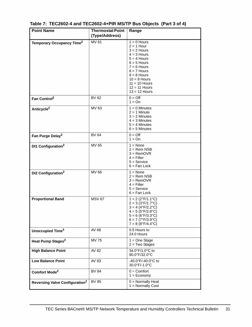
Temporary Occupancy Time2 MV 61 1 = 0 Hours2 = 1 Hour3 = 2 Hours4 = 3 Hours5 = 4 Hours6 = 5 Hours7 = 6 Hours8 = 7 Hours9 = 8 Hours10 = 9 Hours 11 = 10 Hours12 = 11 Hours13 = 12 Hours
Fan Control2 BV 62 0 = Off1 = On
Anticycle2 MV 63 1 = 0 Minutes2 = 1 Minute3 = 2 Minutes4 = 3 Minutes5 = 4 Minutes6 = 5 Minutes
Fan Purge Delay2 BV 64 0 = Off1 = On
DI1 Configuration2 MV 65 1 = None2 = Rem NSB3 = RemOVR4 = Filter5 = Service6 = Fan Lock
DI2 Configuration2 MV 66 1 = None2 = Rem NSB3 = RemOVR4 = Filter5 = Service6 = Fan Lock
Proportional Band MSV 67 1 = 2 (2°F/1.1°C)2 = 3 (3°F/1.7°C)3 = 4 (4°F/2.2°C)4 = 5 (5°F/2.8°C)5 = 6 (6°F/3.3°C)6 = 7 (7°F/3.9°C)7 = 8 (8°F/4.4°C)
Unoccupied Time3 AV 68 0.5 Hours to24.0 Hours
Heat Pump Stages2 MV 75 1 = One Stage2 = Two Stages
High Balance Point AV 82 34.0°F/1.0°C to90.0°F/32.0°C
Low Balance Point AV 83 -40.0°F/-40.0°C to30.0°F/-1.0°C
Comfort Mode2 BV 84 0 = Comfort1 = Economy
Reversing Valve Configuration2 BV 85 0 = Normally Heat1 = Normally Cool
Table 7: TEC2602-4 and TEC2602-4+PIR MS/TP Bus Objects (Part 3 of 4)Point Name Thermostat Point
(Type/Address)Range
TEC Series BACnet® MS/TP Network Temperature and Humidity Controllers Technical Bulletin 31
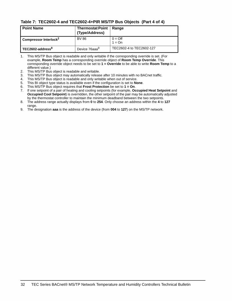
Compressor Interlock2 BV 86 0 = Off1 = On
TEC2602-address8 Device 76aaa9 TEC2602-4 to TEC2602-127
1. This MS/TP Bus object is readable and only writable if the corresponding override is set. (For example, Room Temp has a corresponding override object of Room Temp Override. This corresponding override object needs to be set to 1 = Override to be able to write Room Temp to a different value.)
2. This MS/TP Bus object is readable and writable.3. This MS/TP Bus object may automatically release after 10 minutes with no BACnet traffic.4. This MS/TP Bus object is readable and only writable when out of service.5. This BI object type status is available even if the configuration is set to None.6. This MS/TP Bus object requires that Frost Protection be set to 1 = On.7. If one setpoint of a pair of heating and cooling setpoints (for example, Occupied Heat Setpoint and
Occupied Cool Setpoint) is overridden, the other setpoint of the pair may be automatically adjusted by the thermostat controller to maintain the minimum deadband between the two setpoints.
8. The address range actually displays from 0 to 254. Only choose an address within the 4 to 127 range.
9. The designation aaa is the address of the device (from 004 to 127) on the MS/TP network.
Table 7: TEC2602-4 and TEC2602-4+PIR MS/TP Bus Objects (Part 4 of 4)Point Name Thermostat Point
(Type/Address)Range
TEC Series BACnet® MS/TP Network Temperature and Humidity Controllers Technical Bulletin32
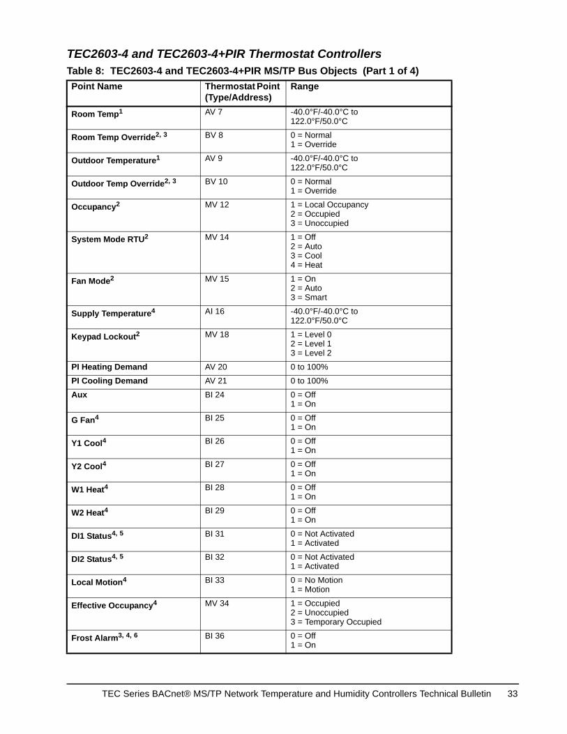
TEC2603-4 and TEC2603-4+PIR Thermostat Controllers Table 8: TEC2603-4 and TEC2603-4+PIR MS/TP Bus Objects (Part 1 of 4)Point Name Thermostat Point
(Type/Address)Range
Room Temp1 AV 7 -40.0°F/-40.0°C to122.0°F/50.0°C
Room Temp Override2, 3 BV 8 0 = Normal1 = Override
Outdoor Temperature1 AV 9 -40.0°F/-40.0°C to122.0°F/50.0°C
Outdoor Temp Override2, 3 BV 10 0 = Normal1 = Override
Occupancy2 MV 12 1 = Local Occupancy2 = Occupied3 = Unoccupied
System Mode RTU2 MV 14 1 = Off2 = Auto3 = Cool4 = Heat
Fan Mode2 MV 15 1 = On2 = Auto3 = Smart
Supply Temperature4 AI 16 -40.0°F/-40.0°C to122.0°F/50.0°C
Keypad Lockout2 MV 18 1 = Level 02 = Level 13 = Level 2
PI Heating Demand AV 20 0 to 100%
PI Cooling Demand AV 21 0 to 100%
Aux BI 24 0 = Off1 = On
G Fan4 BI 25 0 = Off1 = On
Y1 Cool4 BI 26 0 = Off1 = On
Y2 Cool4 BI 27 0 = Off1 = On
W1 Heat4 BI 28 0 = Off1 = On
W2 Heat4 BI 29 0 = Off1 = On
DI1 Status4, 5 BI 31 0 = Not Activated1 = Activated
DI2 Status4, 5 BI 32 0 = Not Activated1 = Activated
Local Motion4 BI 33 0 = No Motion1 = Motion
Effective Occupancy4 MV 34 1 = Occupied2 = Unoccupied3 = Temporary Occupied
Frost Alarm3, 4, 6 BI 36 0 = Off1 = On
TEC Series BACnet® MS/TP Network Temperature and Humidity Controllers Technical Bulletin 33

Filter Alarm4 BI 38 0 = Off1 = On
Service Alarm4 BI 39 0 = Off1 = On
Fan Lock Alarm4 BI 40 0 = Off1 = On
Occupied Heat Setpoint2, 7 AV 42 40.0°F/4.5°C to90.0°F/32.0°C
Occupied Cool Setpoint2, 7 AV 43 54.0°F/12.0°C to100.0°F/37.5°C
Unoccupied Heat Setpoint2, 7 AV 44 40.0°F/4.5°C to90.0°F/32.0°C
Unoccupied Cool Setpoint2, 7 AV 45 54.0°F/12.0°C to100.0°F/37.5°C
Temperature Scale2 BV 47 0 = °C1 = °F
Heating Setpoint Limit2 AV 48 40.0°F/4.5°C to90.0°F/32.0°C
Cooling Setpoint Limit2 AV 49 54.0°F/12.0°C to100.0°F/37.5°C
Heating Lockout Temperature2 AV 50 -15.0°F/-26.0°C to120.0°F/49.0°C
Cooling Lockout Temperature2 AV 51 -40.0°F/-40.0°C to95.0°F/35.0°C
Deadband2 AV 52 2.0F°/1.0C° to 4.0F°/2.0C°
Heating CPH2 MV 53 1 = 3 CPH2 = 4 CPH3 = 5 CPH4 = 6 CPH5 = 7 CPH6 = 8 CPH
Cooling CPH2 MV 54 1 = 3 CPH2 = 4 CPH
Frost Protection2 BV 55 0 = Off1 = On
Aux Contact2 BV 56 0 = Normally Open (N.O.)1 = Normally Closed (N.C.)
Menu Scroll2 BV 57 0 = No Scroll1 = Scroll Active
Password Value AV 59 0 to 1,000
Power Up Delay2 AV 60 10 to 120 Seconds
Table 8: TEC2603-4 and TEC2603-4+PIR MS/TP Bus Objects (Part 2 of 4)Point Name Thermostat Point
(Type/Address)Range
TEC Series BACnet® MS/TP Network Temperature and Humidity Controllers Technical Bulletin34
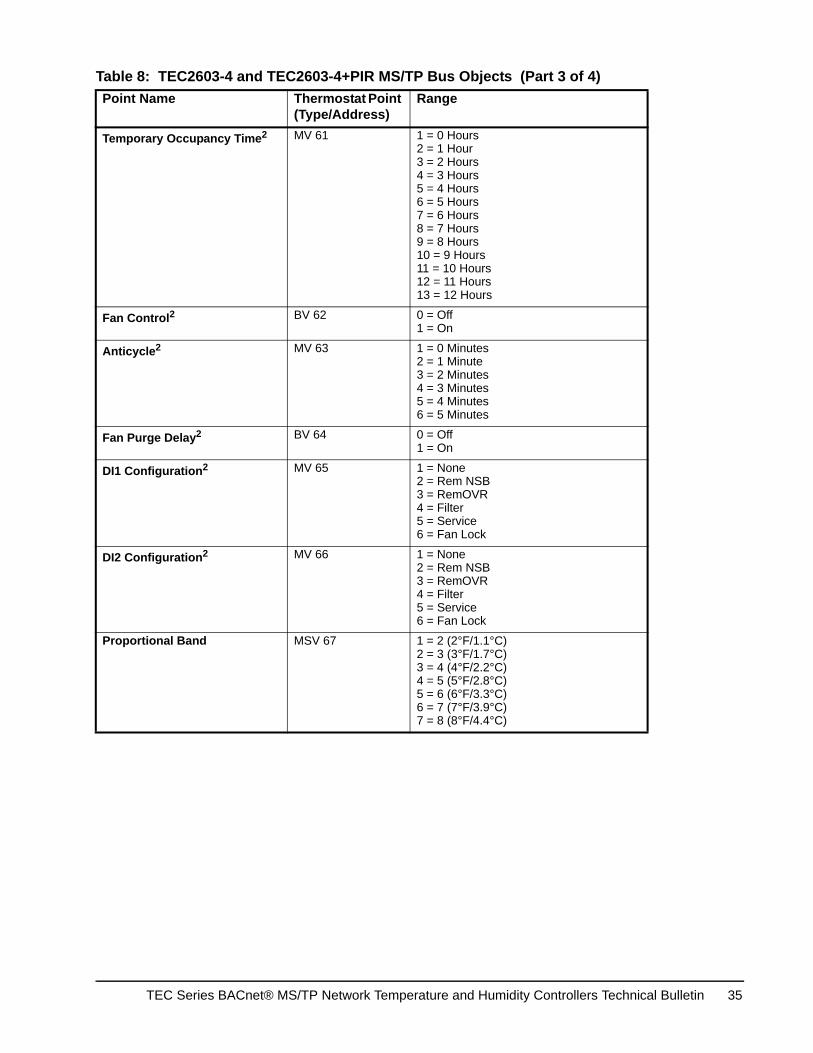
Temporary Occupancy Time2 MV 61 1 = 0 Hours2 = 1 Hour3 = 2 Hours4 = 3 Hours5 = 4 Hours6 = 5 Hours7 = 6 Hours8 = 7 Hours9 = 8 Hours10 = 9 Hours 11 = 10 Hours12 = 11 Hours13 = 12 Hours
Fan Control2 BV 62 0 = Off1 = On
Anticycle2 MV 63 1 = 0 Minutes2 = 1 Minute3 = 2 Minutes4 = 3 Minutes5 = 4 Minutes6 = 5 Minutes
Fan Purge Delay2 BV 64 0 = Off1 = On
DI1 Configuration2 MV 65 1 = None2 = Rem NSB3 = RemOVR4 = Filter5 = Service6 = Fan Lock
DI2 Configuration2 MV 66 1 = None2 = Rem NSB3 = RemOVR4 = Filter5 = Service6 = Fan Lock
Proportional Band MSV 67 1 = 2 (2°F/1.1°C)2 = 3 (3°F/1.7°C)3 = 4 (4°F/2.2°C)4 = 5 (5°F/2.8°C)5 = 6 (6°F/3.3°C)6 = 7 (7°F/3.9°C)7 = 8 (8°F/4.4°C)
Table 8: TEC2603-4 and TEC2603-4+PIR MS/TP Bus Objects (Part 3 of 4)Point Name Thermostat Point
(Type/Address)Range
TEC Series BACnet® MS/TP Network Temperature and Humidity Controllers Technical Bulletin 35
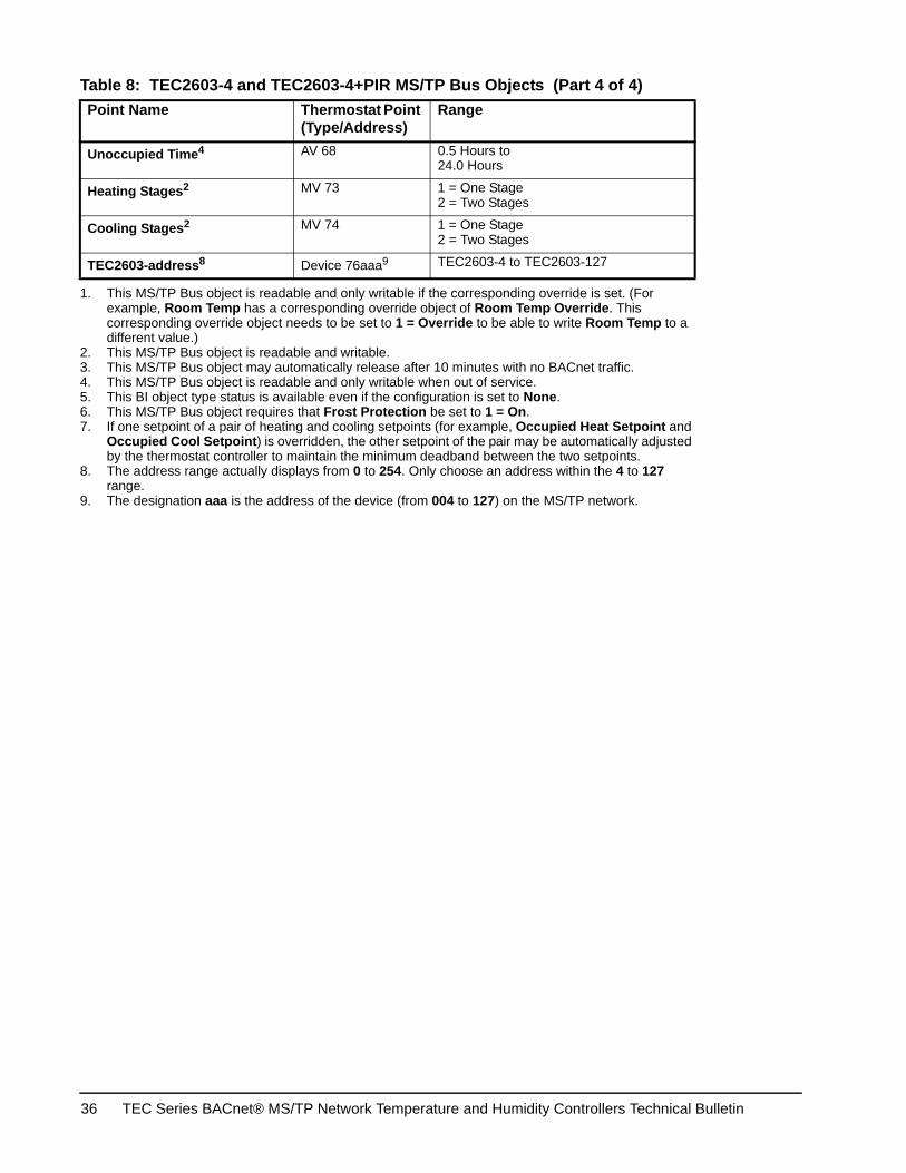
Unoccupied Time4 AV 68 0.5 Hours to24.0 Hours
Heating Stages2 MV 73 1 = One Stage2 = Two Stages
Cooling Stages2 MV 74 1 = One Stage2 = Two Stages
TEC2603-address8 Device 76aaa9 TEC2603-4 to TEC2603-127
1. This MS/TP Bus object is readable and only writable if the corresponding override is set. (For example, Room Temp has a corresponding override object of Room Temp Override. This corresponding override object needs to be set to 1 = Override to be able to write Room Temp to a different value.)
2. This MS/TP Bus object is readable and writable.3. This MS/TP Bus object may automatically release after 10 minutes with no BACnet traffic.4. This MS/TP Bus object is readable and only writable when out of service.5. This BI object type status is available even if the configuration is set to None.6. This MS/TP Bus object requires that Frost Protection be set to 1 = On.7. If one setpoint of a pair of heating and cooling setpoints (for example, Occupied Heat Setpoint and
Occupied Cool Setpoint) is overridden, the other setpoint of the pair may be automatically adjusted by the thermostat controller to maintain the minimum deadband between the two setpoints.
8. The address range actually displays from 0 to 254. Only choose an address within the 4 to 127 range.
9. The designation aaa is the address of the device (from 004 to 127) on the MS/TP network.
Table 8: TEC2603-4 and TEC2603-4+PIR MS/TP Bus Objects (Part 4 of 4)Point Name Thermostat Point
(Type/Address)Range
TEC Series BACnet® MS/TP Network Temperature and Humidity Controllers Technical Bulletin36
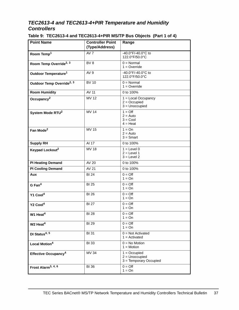
TEC2613-4 and TEC2613-4+PIR Temperature and Humidity Controllers Table 9: TEC2613-4 and TEC2613-4+PIR MS/TP Bus Objects (Part 1 of 4)Point Name Controller Point
(Type/Address)Range
Room Temp1 AV 7 -40.0°F/-40.0°C to122.0°F/50.0°C
Room Temp Override2, 3 BV 8 0 = Normal1 = Override
Outdoor Temperature1 AV 9 -40.0°F/-40.0°C to122.0°F/50.0°C
Outdoor Temp Override2, 3 BV 10 0 = Normal1 = Override
Room Humidity AV 11 0 to 100%
Occupancy2 MV 12 1 = Local Occupancy2 = Occupied3 = Unoccupied
System Mode RTU2 MV 14 1 = Off2 = Auto3 = Cool4 = Heat
Fan Mode2 MV 15 1 = On2 = Auto3 = Smart
Supply RH AI 17 0 to 100%
Keypad Lockout2 MV 18 1 = Level 02 = Level 13 = Level 2
PI Heating Demand AV 20 0 to 100%
PI Cooling Demand AV 21 0 to 100%
Aux BI 24 0 = Off1 = On
G Fan4 BI 25 0 = Off1 = On
Y1 Cool4 BI 26 0 = Off1 = On
Y2 Cool4 BI 27 0 = Off1 = On
W1 Heat4 BI 28 0 = Off1 = On
W2 Heat4 BI 29 0 = Off1 = On
DI Status4, 5 BI 31 0 = Not Activated1 = Activated
Local Motion4 BI 33 0 = No Motion1 = Motion
Effective Occupancy4 MV 34 1 = Occupied2 = Unoccupied3 = Temporary Occupied
Frost Alarm3, 4, 6 BI 36 0 = Off1 = On
TEC Series BACnet® MS/TP Network Temperature and Humidity Controllers Technical Bulletin 37

Filter Alarm4 BI 38 0 = Off1 = On
Service Alarm4 BI 39 0 = Off1 = On
Fan Lock Alarm4 BI 40 0 = Off1 = On
Occupied Heat Setpoint2, 7 AV 42 40.0°F/4.5°C to90.0°F/32.0°C
Occupied Cool Setpoint2, 7 AV 43 54.0°F/12.0°C to100.0°F/37.5°C
Unoccupied Heat Setpoint2, 7 AV 44 40.0°F/4.5°C to90.0°F/32.0°C
Unoccupied Cool Setpoint2, 7 AV 45 54.0°F/12.0°C to100.0°F/37.5°C
Temperature Scale2 BV 47 0 = °C1 = °F
Heating Setpoint Limit2 AV 48 40.0°F/4.5°C to90.0°F/32.0°C
Cooling Setpoint Limit2 AV 49 54.0°F/12.0°C to100.0°F/37.5°C
Heating Lockout Temperature2 AV 50 -15.0°F/-26.0°C to120.0°F/49.0°C
Cooling Lockout Temperature2 AV 51 -40.0°F/-40.0°C to95.0°F/35.0°C
Deadband2 AV 52 2.0F°/1.0C° to 4.0F°/2.0C°
Heating CPH2 MV 53 1 = 3 CPH2 = 4 CPH3 = 5 CPH4 = 6 CPH5 = 7 CPH6 = 8 CPH
Cooling CPH2 MV 54 1 = 3 CPH2 = 4 CPH
Frost Protection2 BV 55 0 = Off1 = On
Aux Contact2 BV 56 0 = Normally Open (N.O.)1 = Normally Closed (N.C.)
Menu Scroll2 BV 57 0 = No Scroll1 = Scroll Active
Password Value AV 59 0 to 1,000
Power Up Delay2 AV 60 10 to 120 Seconds
Table 9: TEC2613-4 and TEC2613-4+PIR MS/TP Bus Objects (Part 2 of 4)Point Name Controller Point
(Type/Address)Range
TEC Series BACnet® MS/TP Network Temperature and Humidity Controllers Technical Bulletin38
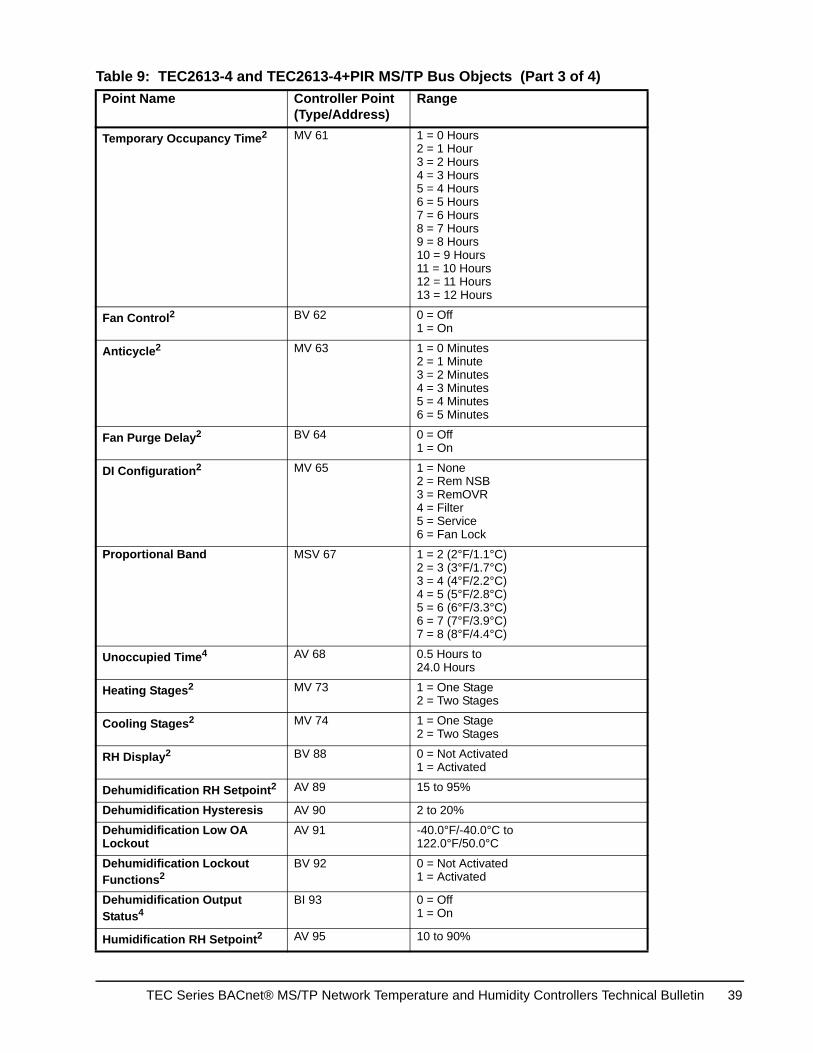
Temporary Occupancy Time2 MV 61 1 = 0 Hours2 = 1 Hour3 = 2 Hours4 = 3 Hours5 = 4 Hours6 = 5 Hours7 = 6 Hours8 = 7 Hours9 = 8 Hours10 = 9 Hours 11 = 10 Hours12 = 11 Hours13 = 12 Hours
Fan Control2 BV 62 0 = Off1 = On
Anticycle2 MV 63 1 = 0 Minutes2 = 1 Minute3 = 2 Minutes4 = 3 Minutes5 = 4 Minutes6 = 5 Minutes
Fan Purge Delay2 BV 64 0 = Off1 = On
DI Configuration2 MV 65 1 = None2 = Rem NSB3 = RemOVR4 = Filter5 = Service6 = Fan Lock
Proportional Band MSV 67 1 = 2 (2°F/1.1°C)2 = 3 (3°F/1.7°C)3 = 4 (4°F/2.2°C)4 = 5 (5°F/2.8°C)5 = 6 (6°F/3.3°C)6 = 7 (7°F/3.9°C)7 = 8 (8°F/4.4°C)
Unoccupied Time4 AV 68 0.5 Hours to24.0 Hours
Heating Stages2 MV 73 1 = One Stage2 = Two Stages
Cooling Stages2 MV 74 1 = One Stage2 = Two Stages
RH Display2 BV 88 0 = Not Activated1 = Activated
Dehumidification RH Setpoint2 AV 89 15 to 95%
Dehumidification Hysteresis AV 90 2 to 20%
Dehumidification Low OA Lockout
AV 91 -40.0°F/-40.0°C to122.0°F/50.0°C
Dehumidification Lockout Functions2
BV 92 0 = Not Activated1 = Activated
Dehumidification Output Status4
BI 93 0 = Off1 = On
Humidification RH Setpoint2 AV 95 10 to 90%
Table 9: TEC2613-4 and TEC2613-4+PIR MS/TP Bus Objects (Part 3 of 4)Point Name Controller Point
(Type/Address)Range
TEC Series BACnet® MS/TP Network Temperature and Humidity Controllers Technical Bulletin 39
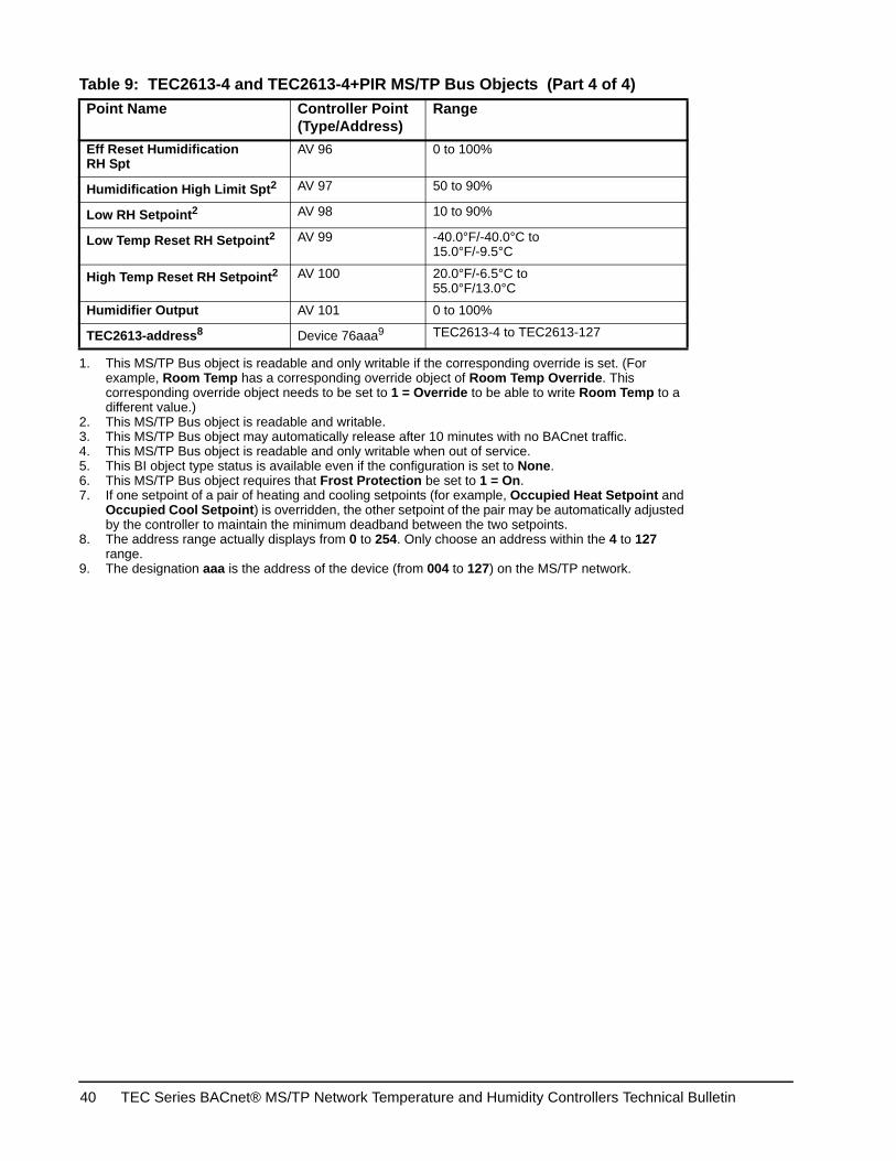
Eff Reset Humidification RH Spt
AV 96 0 to 100%
Humidification High Limit Spt2 AV 97 50 to 90%
Low RH Setpoint2 AV 98 10 to 90%
Low Temp Reset RH Setpoint2 AV 99 -40.0°F/-40.0°C to15.0°F/-9.5°C
High Temp Reset RH Setpoint2 AV 100 20.0°F/-6.5°C to55.0°F/13.0°C
Humidifier Output AV 101 0 to 100%
TEC2613-address8 Device 76aaa9 TEC2613-4 to TEC2613-127
1. This MS/TP Bus object is readable and only writable if the corresponding override is set. (For example, Room Temp has a corresponding override object of Room Temp Override. This corresponding override object needs to be set to 1 = Override to be able to write Room Temp to a different value.)
2. This MS/TP Bus object is readable and writable.3. This MS/TP Bus object may automatically release after 10 minutes with no BACnet traffic.4. This MS/TP Bus object is readable and only writable when out of service.5. This BI object type status is available even if the configuration is set to None.6. This MS/TP Bus object requires that Frost Protection be set to 1 = On.7. If one setpoint of a pair of heating and cooling setpoints (for example, Occupied Heat Setpoint and
Occupied Cool Setpoint) is overridden, the other setpoint of the pair may be automatically adjusted by the controller to maintain the minimum deadband between the two setpoints.
8. The address range actually displays from 0 to 254. Only choose an address within the 4 to 127 range.
9. The designation aaa is the address of the device (from 004 to 127) on the MS/TP network.
Table 9: TEC2613-4 and TEC2613-4+PIR MS/TP Bus Objects (Part 4 of 4)Point Name Controller Point
(Type/Address)Range
TEC Series BACnet® MS/TP Network Temperature and Humidity Controllers Technical Bulletin40
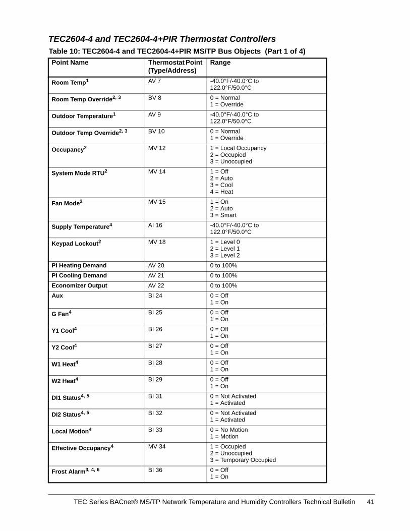
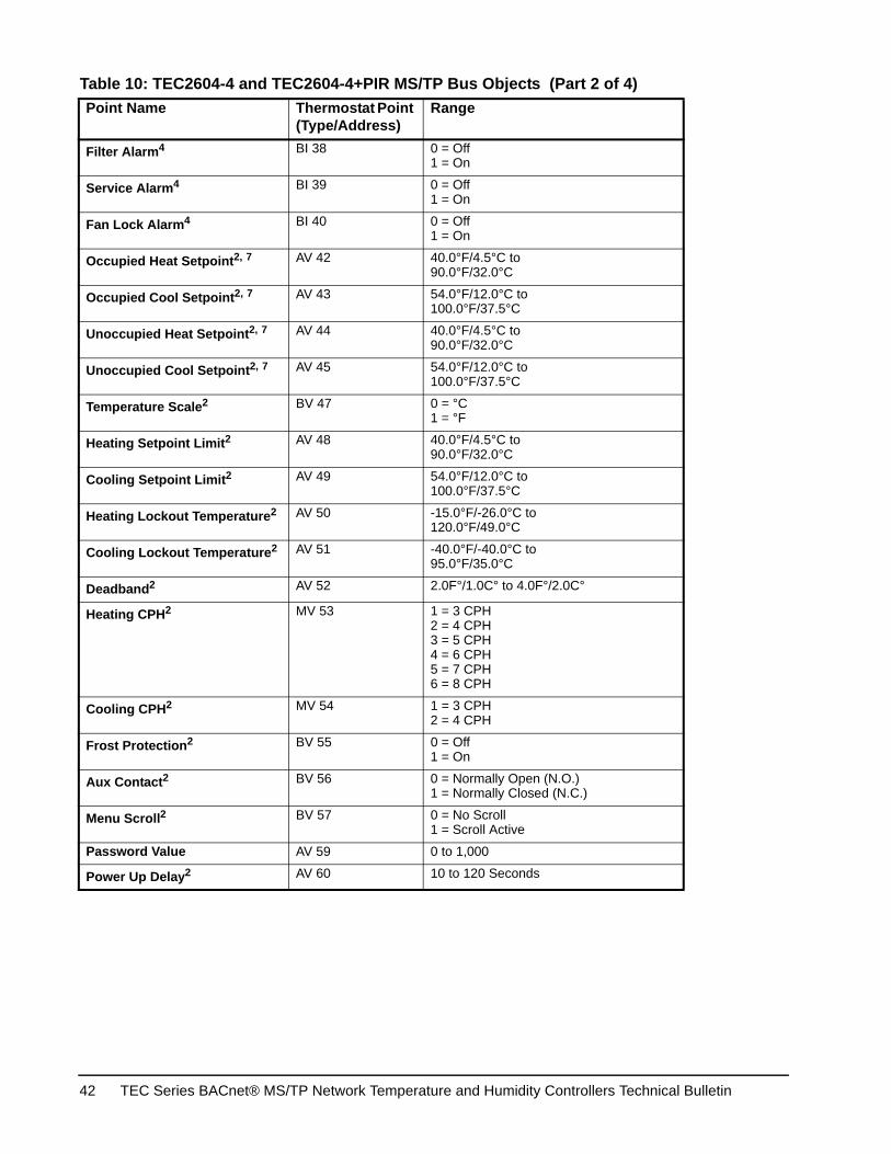
TEC2604-4 and TEC2604-4+PIR Thermostat Controllers Table 10: TEC2604-4 and TEC2604-4+PIR MS/TP Bus Objects (Part 1 of 4)Point Name Thermostat Point
(Type/Address)Range
Room Temp1 AV 7 -40.0°F/-40.0°C to122.0°F/50.0°C
Room Temp Override2, 3 BV 8 0 = Normal1 = Override
Outdoor Temperature1 AV 9 -40.0°F/-40.0°C to122.0°F/50.0°C
Outdoor Temp Override2, 3 BV 10 0 = Normal1 = Override
Occupancy2 MV 12 1 = Local Occupancy2 = Occupied3 = Unoccupied
System Mode RTU2 MV 14 1 = Off2 = Auto3 = Cool4 = Heat
Fan Mode2 MV 15 1 = On2 = Auto3 = Smart
Supply Temperature4 AI 16 -40.0°F/-40.0°C to122.0°F/50.0°C
Keypad Lockout2 MV 18 1 = Level 02 = Level 13 = Level 2
PI Heating Demand AV 20 0 to 100%
PI Cooling Demand AV 21 0 to 100%
Economizer Output AV 22 0 to 100%
Aux BI 24 0 = Off1 = On
G Fan4 BI 25 0 = Off1 = On
Y1 Cool4 BI 26 0 = Off1 = On
Y2 Cool4 BI 27 0 = Off1 = On
W1 Heat4 BI 28 0 = Off1 = On
W2 Heat4 BI 29 0 = Off1 = On
DI1 Status4, 5 BI 31 0 = Not Activated1 = Activated
DI2 Status4, 5 BI 32 0 = Not Activated1 = Activated
Local Motion4 BI 33 0 = No Motion1 = Motion
Effective Occupancy4 MV 34 1 = Occupied2 = Unoccupied3 = Temporary Occupied
Frost Alarm3, 4, 6 BI 36 0 = Off1 = On
TEC Series BACnet® MS/TP Network Temperature and Humidity Controllers Technical Bulletin 41
Filter Alarm4 BI 38 0 = Off1 = On
Service Alarm4 BI 39 0 = Off1 = On
Fan Lock Alarm4 BI 40 0 = Off1 = On
Occupied Heat Setpoint2, 7 AV 42 40.0°F/4.5°C to90.0°F/32.0°C
Occupied Cool Setpoint2, 7 AV 43 54.0°F/12.0°C to100.0°F/37.5°C
Unoccupied Heat Setpoint2, 7 AV 44 40.0°F/4.5°C to90.0°F/32.0°C
Unoccupied Cool Setpoint2, 7 AV 45 54.0°F/12.0°C to100.0°F/37.5°C
Temperature Scale2 BV 47 0 = °C1 = °F
Heating Setpoint Limit2 AV 48 40.0°F/4.5°C to90.0°F/32.0°C
Cooling Setpoint Limit2 AV 49 54.0°F/12.0°C to100.0°F/37.5°C
Heating Lockout Temperature2 AV 50 -15.0°F/-26.0°C to120.0°F/49.0°C
Cooling Lockout Temperature2 AV 51 -40.0°F/-40.0°C to95.0°F/35.0°C
Deadband2 AV 52 2.0F°/1.0C° to 4.0F°/2.0C°
Heating CPH2 MV 53 1 = 3 CPH2 = 4 CPH3 = 5 CPH4 = 6 CPH5 = 7 CPH6 = 8 CPH
Cooling CPH2 MV 54 1 = 3 CPH2 = 4 CPH
Frost Protection2 BV 55 0 = Off1 = On
Aux Contact2 BV 56 0 = Normally Open (N.O.)1 = Normally Closed (N.C.)
Menu Scroll2 BV 57 0 = No Scroll1 = Scroll Active
Password Value AV 59 0 to 1,000
Power Up Delay2 AV 60 10 to 120 Seconds
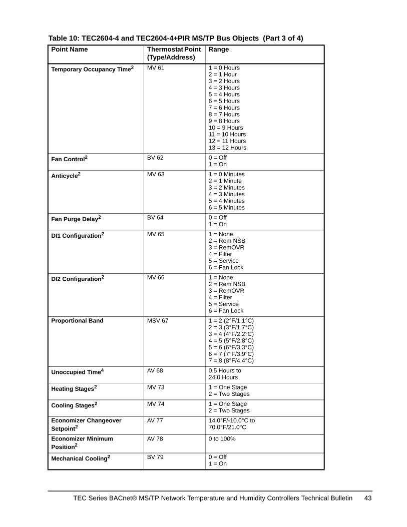
Table 10: TEC2604-4 and TEC2604-4+PIR MS/TP Bus Objects (Part 2 of 4)Point Name Thermostat Point
(Type/Address)Range
TEC Series BACnet® MS/TP Network Temperature and Humidity Controllers Technical Bulletin42
Temporary Occupancy Time2 MV 61 1 = 0 Hours2 = 1 Hour3 = 2 Hours4 = 3 Hours5 = 4 Hours6 = 5 Hours7 = 6 Hours8 = 7 Hours9 = 8 Hours10 = 9 Hours 11 = 10 Hours12 = 11 Hours13 = 12 Hours
Fan Control2 BV 62 0 = Off1 = On
Anticycle2 MV 63 1 = 0 Minutes2 = 1 Minute3 = 2 Minutes4 = 3 Minutes5 = 4 Minutes6 = 5 Minutes
Fan Purge Delay2 BV 64 0 = Off1 = On
DI1 Configuration2 MV 65 1 = None2 = Rem NSB3 = RemOVR4 = Filter5 = Service6 = Fan Lock
DI2 Configuration2 MV 66 1 = None2 = Rem NSB3 = RemOVR4 = Filter5 = Service6 = Fan Lock
Proportional Band MSV 67 1 = 2 (2°F/1.1°C)2 = 3 (3°F/1.7°C)3 = 4 (4°F/2.2°C)4 = 5 (5°F/2.8°C)5 = 6 (6°F/3.3°C)6 = 7 (7°F/3.9°C)7 = 8 (8°F/4.4°C)
Unoccupied Time4 AV 68 0.5 Hours to24.0 Hours
Heating Stages2 MV 73 1 = One Stage2 = Two Stages
Cooling Stages2 MV 74 1 = One Stage2 = Two Stages
Economizer Changeover Setpoint2
AV 77 14.0°F/-10.0°C to70.0°F/21.0°C
Economizer Minimum Position2
AV 78 0 to 100%
Mechanical Cooling2 BV 79 0 = Off1 = On
Table 10: TEC2604-4 and TEC2604-4+PIR MS/TP Bus Objects (Part 3 of 4)Point Name Thermostat Point
(Type/Address)Range
TEC Series BACnet® MS/TP Network Temperature and Humidity Controllers Technical Bulletin 43
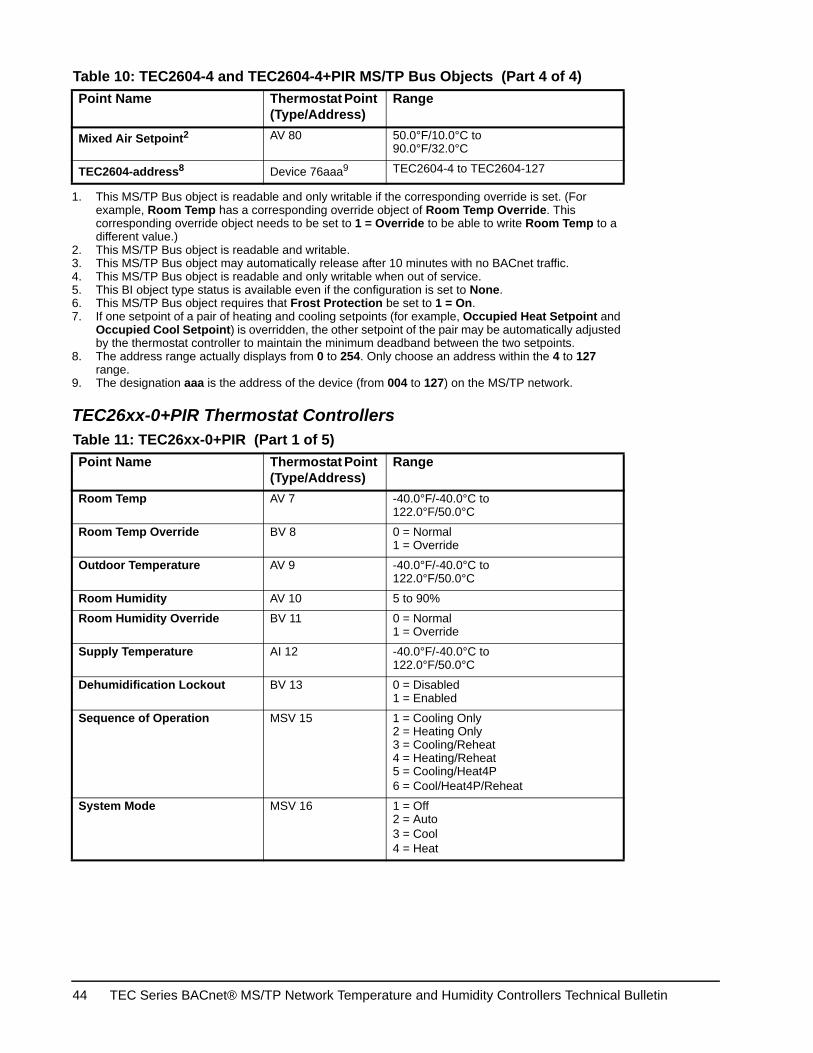
TEC26xx-0+PIR Thermostat Controllers
Mixed Air Setpoint2 AV 80 50.0°F/10.0°C to90.0°F/32.0°C
TEC2604-address8 Device 76aaa9 TEC2604-4 to TEC2604-127
1. This MS/TP Bus object is readable and only writable if the corresponding override is set. (For example, Room Temp has a corresponding override object of Room Temp Override. This corresponding override object needs to be set to 1 = Override to be able to write Room Temp to a different value.)
2. This MS/TP Bus object is readable and writable.3. This MS/TP Bus object may automatically release after 10 minutes with no BACnet traffic.4. This MS/TP Bus object is readable and only writable when out of service.5. This BI object type status is available even if the configuration is set to None.6. This MS/TP Bus object requires that Frost Protection be set to 1 = On.7. If one setpoint of a pair of heating and cooling setpoints (for example, Occupied Heat Setpoint and
Occupied Cool Setpoint) is overridden, the other setpoint of the pair may be automatically adjusted by the thermostat controller to maintain the minimum deadband between the two setpoints.
8. The address range actually displays from 0 to 254. Only choose an address within the 4 to 127 range.
9. The designation aaa is the address of the device (from 004 to 127) on the MS/TP network.
Table 11: TEC26xx-0+PIR (Part 1 of 5)Point Name Thermostat Point
(Type/Address)Range
Room Temp AV 7 -40.0°F/-40.0°C to122.0°F/50.0°C
Room Temp Override BV 8 0 = Normal1 = Override
Outdoor Temperature AV 9 -40.0°F/-40.0°C to122.0°F/50.0°C
Room Humidity AV 10 5 to 90%
Room Humidity Override BV 11 0 = Normal1 = Override
Supply Temperature AI 12 -40.0°F/-40.0°C to122.0°F/50.0°C
Dehumidification Lockout BV 13 0 = Disabled1 = Enabled
Sequence of Operation MSV 15 1 = Cooling Only2 = Heating Only3 = Cooling/Reheat4 = Heating/Reheat5 = Cooling/Heat4P6 = Cool/Heat4P/Reheat
System Mode MSV 16 1 = Off2 = Auto3 = Cool4 = Heat
Table 10: TEC2604-4 and TEC2604-4+PIR MS/TP Bus Objects (Part 4 of 4)Point Name Thermostat Point
(Type/Address)Range
TEC Series BACnet® MS/TP Network Temperature and Humidity Controllers Technical Bulletin44
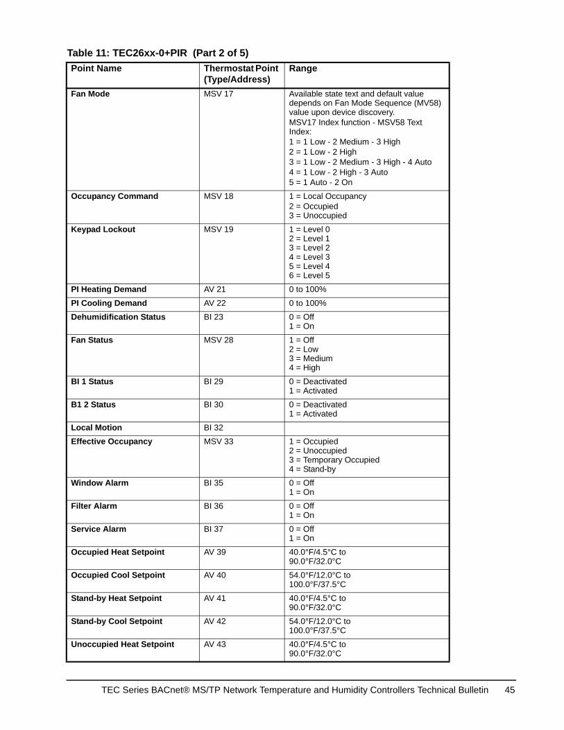
Fan Mode MSV 17 Available state text and default value depends on Fan Mode Sequence (MV58) value upon device discovery.MSV17 Index function - MSV58 Text Index:1 = 1 Low - 2 Medium - 3 High2 = 1 Low - 2 High3 = 1 Low - 2 Medium - 3 High - 4 Auto4 = 1 Low - 2 High - 3 Auto5 = 1 Auto - 2 On
Occupancy Command MSV 18 1 = Local Occupancy2 = Occupied3 = Unoccupied
Keypad Lockout MSV 19 1 = Level 02 = Level 13 = Level 24 = Level 35 = Level 46 = Level 5
PI Heating Demand AV 21 0 to 100%
PI Cooling Demand AV 22 0 to 100%
Dehumidification Status BI 23 0 = Off1 = On
Fan Status MSV 28 1 = Off2 = Low3 = Medium4 = High
BI 1 Status BI 29 0 = Deactivated1 = Activated
B1 2 Status BI 30 0 = Deactivated1 = Activated
Local Motion BI 32
Effective Occupancy MSV 33 1 = Occupied2 = Unoccupied3 = Temporary Occupied4 = Stand-by
Window Alarm BI 35 0 = Off1 = On
Filter Alarm BI 36 0 = Off1 = On
Service Alarm BI 37 0 = Off1 = On
Occupied Heat Setpoint AV 39 40.0°F/4.5°C to90.0°F/32.0°C
Occupied Cool Setpoint AV 40 54.0°F/12.0°C to100.0°F/37.5°C
Stand-by Heat Setpoint AV 41 40.0°F/4.5°C to90.0°F/32.0°C
Stand-by Cool Setpoint AV 42 54.0°F/12.0°C to100.0°F/37.5°C
Unoccupied Heat Setpoint AV 43 40.0°F/4.5°C to90.0°F/32.0°C
Table 11: TEC26xx-0+PIR (Part 2 of 5)Point Name Thermostat Point
(Type/Address)Range
TEC Series BACnet® MS/TP Network Temperature and Humidity Controllers Technical Bulletin 45
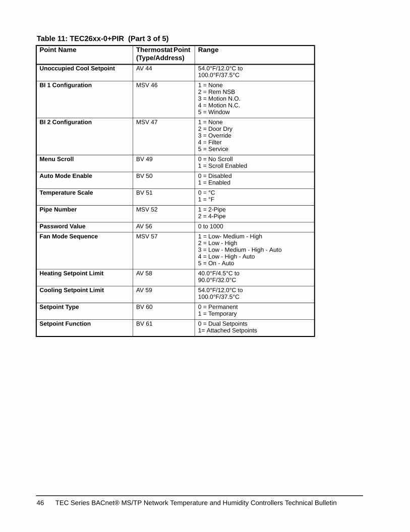
Unoccupied Cool Setpoint AV 44 54.0°F/12.0°C to100.0°F/37.5°C
BI 1 Configuration MSV 46 1 = None2 = Rem NSB3 = Motion N.O.4 = Motion N.C.5 = Window
BI 2 Configuration MSV 47 1 = None2 = Door Dry3 = Override4 = Filter5 = Service
Menu Scroll BV 49 0 = No Scroll1 = Scroll Enabled
Auto Mode Enable BV 50 0 = Disabled1 = Enabled
Temperature Scale BV 51 0 = °C1 = °F
Pipe Number MSV 52 1 = 2-Pipe2 = 4-Pipe
Password Value AV 56 0 to 1000
Fan Mode Sequence MSV 57 1 = Low- Medium - High2 = Low - High3 = Low - Medium - High - Auto4 = Low - High - Auto5 = On - Auto
Heating Setpoint Limit AV 58 40.0°F/4.5°C to90.0°F/32.0°C
Cooling Setpoint Limit AV 59 54.0°F/12.0°C to100.0°F/37.5°C
Setpoint Type BV 60 0 = Permanent1 = Temporary
Setpoint Function BV 61 0 = Dual Setpoints1= Attached Setpoints
Table 11: TEC26xx-0+PIR (Part 3 of 5)Point Name Thermostat Point
(Type/Address)Range
TEC Series BACnet® MS/TP Network Temperature and Humidity Controllers Technical Bulletin46
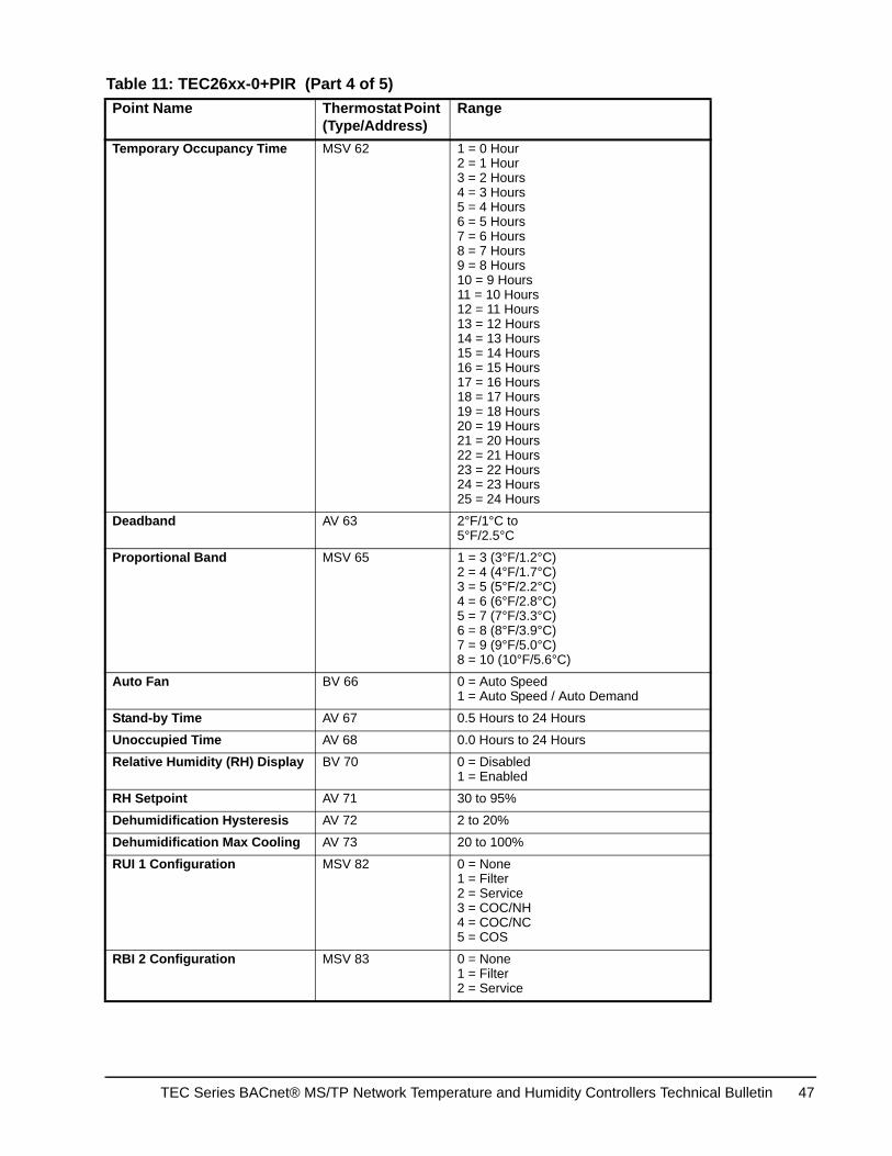
Temporary Occupancy Time MSV 62 1 = 0 Hour2 = 1 Hour3 = 2 Hours4 = 3 Hours5 = 4 Hours6 = 5 Hours7 = 6 Hours8 = 7 Hours9 = 8 Hours10 = 9 Hours11 = 10 Hours12 = 11 Hours13 = 12 Hours14 = 13 Hours15 = 14 Hours16 = 15 Hours17 = 16 Hours18 = 17 Hours19 = 18 Hours20 = 19 Hours21 = 20 Hours22 = 21 Hours23 = 22 Hours24 = 23 Hours25 = 24 Hours
Deadband AV 63 2°F/1°C to5°F/2.5°C
Proportional Band MSV 65 1 = 3 (3°F/1.2°C)2 = 4 (4°F/1.7°C)3 = 5 (5°F/2.2°C)4 = 6 (6°F/2.8°C)5 = 7 (7°F/3.3°C)6 = 8 (8°F/3.9°C)7 = 9 (9°F/5.0°C)8 = 10 (10°F/5.6°C)
Auto Fan BV 66 0 = Auto Speed1 = Auto Speed / Auto Demand
Stand-by Time AV 67 0.5 Hours to 24 Hours
Unoccupied Time AV 68 0.0 Hours to 24 Hours
Relative Humidity (RH) Display BV 70 0 = Disabled1 = Enabled
RH Setpoint AV 71 30 to 95%
Dehumidification Hysteresis AV 72 2 to 20%
Dehumidification Max Cooling AV 73 20 to 100%
RUI 1 Configuration MSV 82 0 = None1 = Filter2 = Service3 = COC/NH4 = COC/NC5 = COS
RBI 2 Configuration MSV 83 0 = None1 = Filter2 = Service
Table 11: TEC26xx-0+PIR (Part 4 of 5)Point Name Thermostat Point
(Type/Address)Range
TEC Series BACnet® MS/TP Network Temperature and Humidity Controllers Technical Bulletin 47
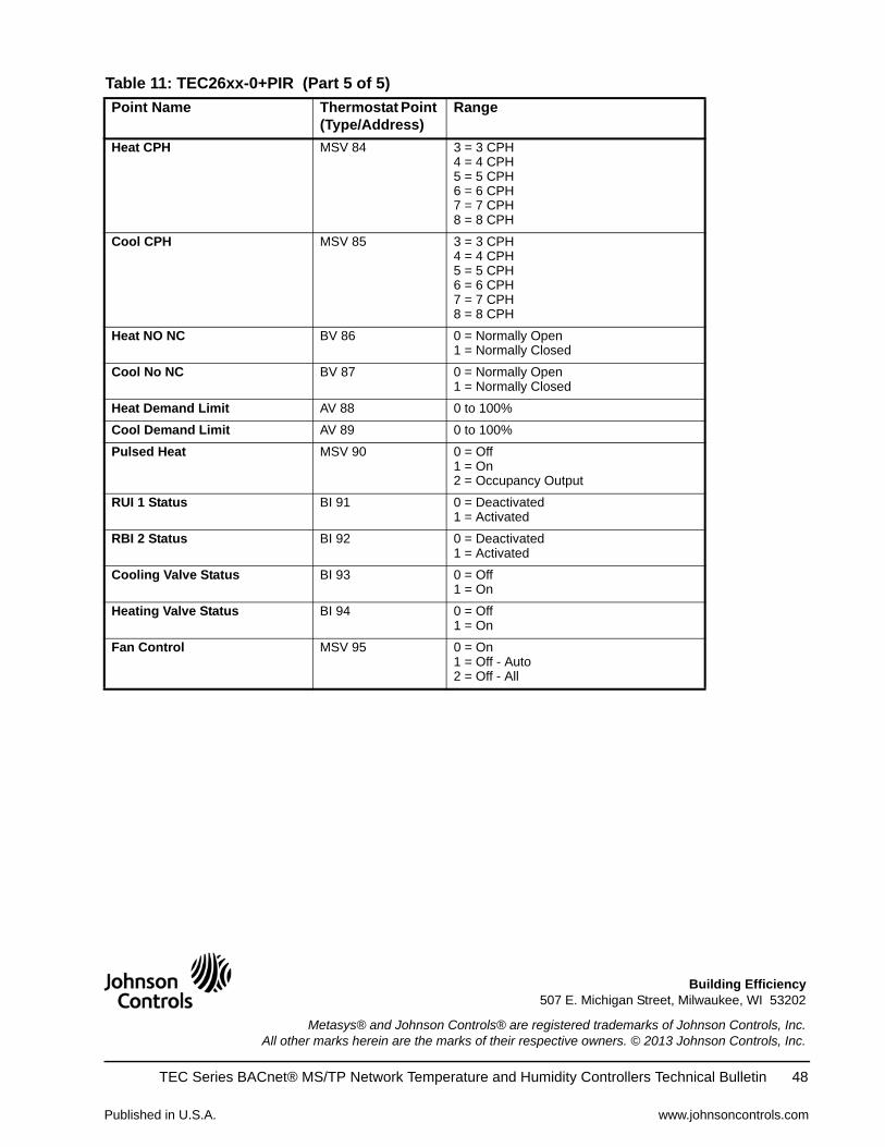
Heat CPH MSV 84 3 = 3 CPH4 = 4 CPH5 = 5 CPH6 = 6 CPH7 = 7 CPH8 = 8 CPH
Cool CPH MSV 85 3 = 3 CPH4 = 4 CPH5 = 5 CPH6 = 6 CPH7 = 7 CPH8 = 8 CPH
Heat NO NC BV 86 0 = Normally Open1 = Normally Closed
Cool No NC BV 87 0 = Normally Open1 = Normally Closed
Heat Demand Limit AV 88 0 to 100%
Cool Demand Limit AV 89 0 to 100%
Pulsed Heat MSV 90 0 = Off1 = On2 = Occupancy Output
RUI 1 Status BI 91 0 = Deactivated1 = Activated
RBI 2 Status BI 92 0 = Deactivated1 = Activated
Cooling Valve Status BI 93 0 = Off1 = On
Heating Valve Status BI 94 0 = Off1 = On
Fan Control MSV 95 0 = On1 = Off - Auto2 = Off - All
Table 11: TEC26xx-0+PIR (Part 5 of 5)Point Name Thermostat Point
(Type/Address)Range
Published in U.S.A. www.johnsoncontrols.com
TEC Series BACnet® MS/TP Network Temperature and Humidity Controllers Technical Bulletin 48
Metasys® and Johnson Controls® are registered trademarks of Johnson Controls, Inc.All other marks herein are the marks of their respective owners. © 2013 Johnson Controls, Inc.
Building Efficiency507 E. Michigan Street, Milwaukee, WI 53202