Embed Size (px)
Citation preview

Convert Working InstructionsACT-MAN-01-04-EN Rev. B
September 2018
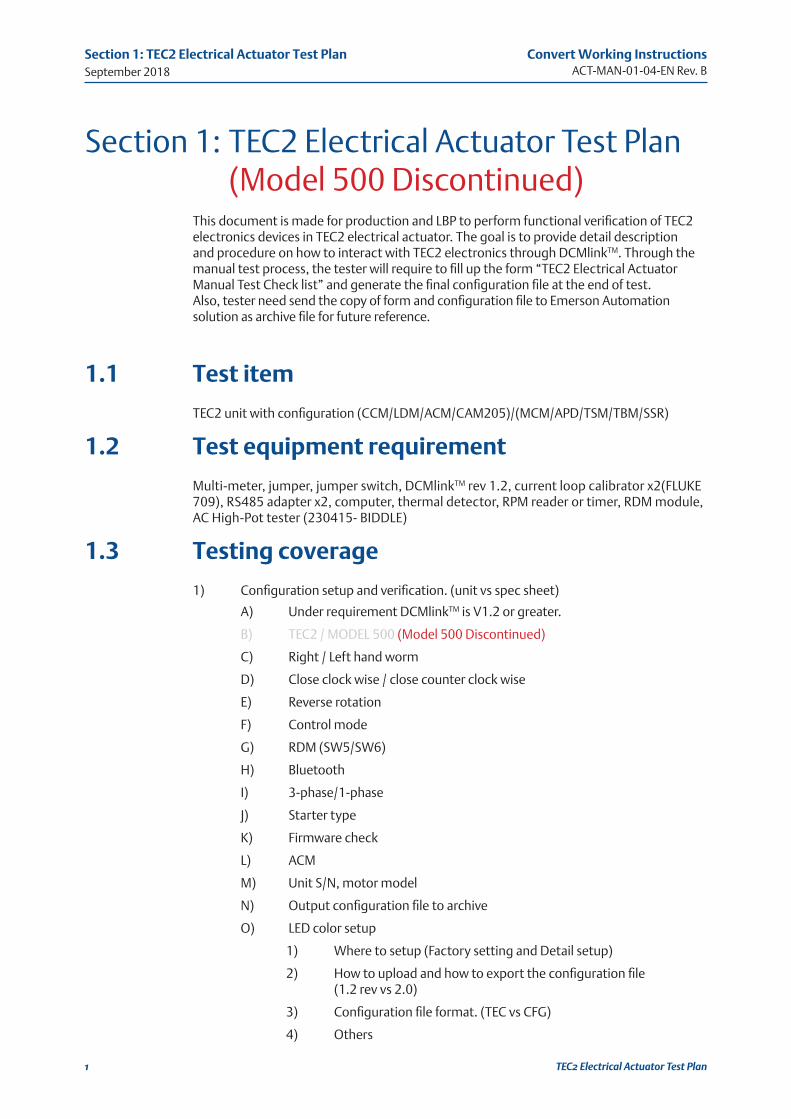
TEC2 Electrical Actuator Test Plan(Model 500 Discontinued)

I
Convert Working InstructionsACT-MAN-01-04-EN Rev. B
Table of ContentsSeptember 2018
Table of Contents
Table of Contents
Section 1: TEC2 Electrical Actuator Test Plan 1.1 Test item ....................................................................................................... 11.2 Test equipment requirement ......................................................................... 11.3 Testing coverage ........................................................................................... 11.4 Test Flow ...................................................................................................... 3
Section 2: TEC2 Electrical Actuator Test Procedure2.1 Insulation resistance; Día-electrical test ........................................................ 62.2 Pre-configuration .......................................................................................... 62.3 Local test / Discrete output test ..................................................................... 72.4 Remote test / Discrete input test ................................................................... 82.5 TEC2 Electrical Actuator Testing Checklist ................................................... 11
Section 3: Reference pictures
September 2018
Convert Working InstructionsACT-MAN-01-04-EN Rev. B
1
Section 1: TEC2 Electrical Actuator Test Plan
TEC2 Electrical Actuator Test Plan
Section 1: TEC2 Electrical Actuator Test Plan (Model 500 Discontinued)This document is made for production and LBP to perform functional verification of TEC2 electronics devices in TEC2 electrical actuator. The goal is to provide detail description and procedure on how to interact with TEC2 electronics through DCMlinkTM. Through the manual test process, the tester will require to fill up the form “TEC2 Electrical Actuator Manual Test Check list” and generate the final configuration file at the end of test. Also, tester need send the copy of form and configuration file to Emerson Automation solution as archive file for future reference.
1.1 Test item
TEC2 unit with configuration (CCM/LDM/ACM/CAM205)/(MCM/APD/TSM/TBM/SSR)
1.2 Test equipment requirement
Multi-meter, jumper, jumper switch, DCMlinkTM rev 1.2, current loop calibrator x2(FLUKE 709), RS485 adapter x2, computer, thermal detector, RPM reader or timer, RDM module, AC High-Pot tester (230415- BIDDLE)
1.3 Testing coverage
1) Configuration setup and verification. (unit vs spec sheet)
A) Under requirement DCMlinkTM is V1.2 or greater.
B) TEC2 / MODEL 500 (Model 500 Discontinued)
C) Right / Left hand worm
D) Close clock wise / close counter clock wise
E) Reverse rotation
F) Control mode
G) RDM (SW5/SW6)
H) Bluetooth
I) 3-phase/1-phase
J) Starter type
K) Firmware check
L) ACM
M) Unit S/N, motor model
N) Output configuration file to archive
O) LED color setup
1) Where to setup (Factory setting and Detail setup)
2) How to upload and how to export the configuration file (1.2 rev vs 2.0)
3) Configuration file format. (TEC vs CFG)
4) Others
Convert Working InstructionsACT-MAN-01-04-EN Rev. B
September 2018
2
Section 1: TEC2 Electrical Actuator Test Plan
TEC2 Electrical Actuator Test Plan
2) Firmware check
A) Verify the firmware number and date code.
B) CCM: 1.0.4
C) LDM: 1.0.4
1) LDM has individual EEPROM for language selection. If the chip programmed incorrect, the LDM will show incorrect EEPROM.
3) LDM display check
A) Make sure the color at backlight is even and LED color
1) Fails: Backlight discolor / missing txt / missing line
B) Make sure the selector knob and control knob able to functional properly
1) Screw is tightened on knob / no obstacle during knob movement
4) APD test
A) Setup travel limit. (at least twice wider than stroke time)
1) Verify the right hand/ left hand worm, close direction, reverse rotation
B) Power cycle at 0%, 50%, 100%.
5) LED check
A) Open / close has expecting color output (Red as close or Green as close)
B) Alarm LED
6) RPM test
A) Verify rpm using RPM reader or timer to count turns per min.
7) Rotation rule check
A) Make sure output is in right orientation
B) Make the final AUX gear box has right orientation
8) Discrete input test
A) Wires control / 3 wires / 2 wires / 3 wires analog
B) Open/Close/ESD inhibit
9) Discrete output test
A) N.C/ N.O in remote
10) Hardware ESD test
A) 20-22 short and failure alarm
11) RDM port test
A) SW5/SW6 and failure alarm
12) Analog input test
A) Analog calibration
13) Analog output test
A) Analog calibration
14) Analog output test
A) Analog calibration
15) DCMlinkTM channel test
A) 115200 fix baud rate without encryption setting.
September 2018
Convert Working InstructionsACT-MAN-01-04-EN Rev. B
3
Section 1: TEC2 Electrical Actuator Test Plan
TEC2 Electrical Actuator Test Plan
16) Network protocol test cam205/cam201
A) 9600 fix baud rate
17) Hi-Pot test (AC; 230415)
A) Apply 2.5KV / 1 second on L1,L2,L3 to ground
18) RDM test
A) Preconfigure RDM and connects to unit to perform remote control
19) Hand-wheel / Power shaft test
A) Enable power shaft to make sure able to operate manually through handwheel and able to release properly when motor runs.
1.4 Test Flow
Figure 1 (Whole unit high level test flow)
Tool list:1. Computer2. Firmware programmer (H-JTAG for CCM) - option3. Firmware programmer (ICD3 for LDM) - option4. RS485 converter x2 (one for 36/38, one for CAM)5. Analog loop calibrator x2 (one for input control, one for output feedback)6. Multimeter (check the relay output)7. 475 handheld (FF and HART)8. FF POWER HUB9. Profitbus modem (BW1257) (suggest profibus simulator + 5V supply)10. Devicenet modem (BW1420) (suggest devicenet simulator + 11-24V supply)11. Crossover cable (MODBUS TCP/IP)12. Bluetooth module13. USB to RS232 (for profibus)14. Hi-POT tester.15. Dyno machine.16. AC current Clamp17. RPM reader.Application List1. TEC2 flasher (CCM/LDM firmware program)2. DCMLink (36/38 control) (Bluetooth control)3. Profibus control application4. Devicenet modem control application5. Device installer (MODBUS-TCP/IP)6. MODBUS-POLL (MODBUS-TCP/IP)Power Requirement1. 60hz and 50hz frequency2. 110VAC to 69VAC with 30A each phase (90% unit coverage)3. 24VDC with 500W
START
END
FIRMWAREDOWNLOAD
LDM
CCMFW
FW
HIGH-POT TEST
BASIC UNITTEST
OPTION COMPONENT
TEST
REWORK
CONFIGURATIONOUTPUT
DYNO TESTDYNO CHECK
CHECKCORRECTTORQUEOUTPUT
70% WITHAC CURRENT
READING
CHECKCORRECTTORQUE
DIRECTION(OPEN/CLOSE)
ASSEMBLYPROCESS
YES
25mins
5mins
ICD3
The unit without ACM/CAM/ART/RDM/BT/DBM
HFS45mins
Option: When thenew firmwarereleased
If rework happened, theTEST PROCESS needs to
start from Hipot
The unit has one ofACM/CAM/ART/RDM/
BT/DBM/HFS5-70mins
Save the finalconfiguration file
Storage toserver (EMERSON/LBP)
70% Torque in OPEN/CLOSE with Current
clamp reading10-25mins
H-JTAG
3 times higher voltage: 2.5 KV, 6mA,1 second
Convert Working InstructionsACT-MAN-01-04-EN Rev. B
September 2018
4
Section 1: TEC2 Electrical Actuator Test Plan
TEC2 Electrical Actuator Test Plan
Figure 2 Basic configuration unit test flow
DCMLINK Configuration
setup/download
FW CHECK
ROTATION RULE CHECK(CW/
CCW)
HANDWHEEL
DISCRETE INPUT
DISCRETE OUTPUT
KNOB
LDM DISPLAY CHECK
APD TEST
LIMIT SETTEST
(3 MINS stroke time)
POWER CYCLE
POSITION TEST
(100%,50%,0%)
BASIC UNIT TEST
CCM FIRMWARENUMBER/DATECODE
LDMFIRMWARENUMBER/DATECODE
VOLTAGE
THREE PHASE/SINGLE PHASE
STARTER TYPE
ROTATIONCW/CCW
RH/LHRV/NO-RV
DISCREET INPUT/
OUTPUT SETUP
TYPE UNITQUAT/MULTITEC2/
MODEL500
ACM?NETWORK?
UNIT SN
Output shelve is correct
Final ouput Aux box is
correct
Release when motor start
Handwheel function when it
engaged
Discrete input 1, 2, 3
(4 wires)(3 wires)(2 wires)
Discrete input4, 5,
6(open/close
inhibit/ESD)
Setup Relay output for
remote
Relay output
1,2,3,4,5
Control knob
1.Setup2.LOCAL
open/close
Selector knob
Remote/STOP/open
LED colorOPEN/CLOSE/ALARM
Handwheel rotation
check
RDMRDM port
check
STC9/10POWER CHECK
Emergency stop check
Backlight check
Even color backgroud
RPM speed check
UNIT WIRING
FULL OPEN/FULL
CLOSE/STOP
Configuration relay output
Enter and Exit out
from Setup
LED colorOPEN/CLOSE/ALARM
Backlight check
Even color backgroud
Connect to STC36/38 with 115200 baud rate
10mins
1mins
1mins
1mins
10mins
10mins
5mins
5mins
10mins
5mins
1mins
1mins
Others
Output
file 1configuration
1. Verify the APD gears with magnetreading is correct for all gears (3mins)
Pre-wires and training.It will be shorter than5 mins.
Pre-wires and training.It will be shorter than5 mins.
Verify the speed for OPEN/CLOSE Are having same reading as spec sheet
Remove disconnect STC20/22 and theunit will be not be able to control andshow no alarm?
1. Verify the STC9/10 with power and STC21/ST23 with RDM communication2. Verify the LDM display is function properly3. Verify the LDM knob is able to controlproperly
Connect to STC36/38 with115200 baud rate
September 2018
Convert Working InstructionsACT-MAN-01-04-EN Rev. B
5
Section 1: TEC2 Electrical Actuator Test Plan
TEC2 Electrical Actuator Test Plan
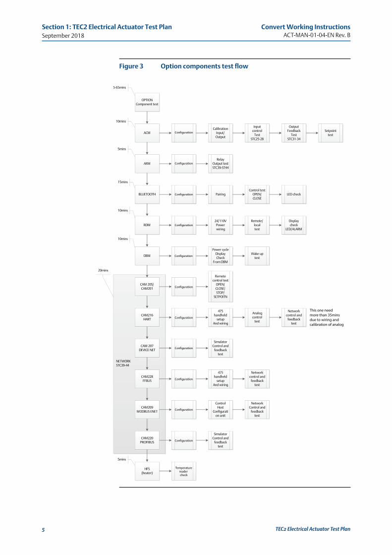
Figure 3 Option components test flow
T E C 2 M A N U A L T E S T P R O C E D U R E P a g e | 7
Option components test flow:
NETWORKSTC39-44
ACM
ARM
CAM 205/CAM201
RDM
DBM
BLUETOOTH
OPTION Component test
CalibrationInput/Output
Input control
TestSTC25-28
OutputFeedback
TestSTC31-34
Setpointtest
RelayOutput testSTC39-ST44
CAM216HART
CAM 207DEVICE NET
CAM228FFBUS
CAM209MODBUS ENET
CAM220PROFIBUS
PairingControl test
OPEN/CLOSE
LED check
24/110V Power wiring
Remote/localtest
Display check
LED/ALARM
Power cycleDisplay Check
From DBM
Wake up test
Remote control test
OPEN/CLOSE/STOP/
SETPOITN
475 handheld
setupAnd wiring
Analog control
test
Network control and
feedback test
SimulatorControl and
feedback test
SimulatorControl and
feedback test
475 handheld
setupAnd wiring
Network control and
feedback test
Control Host
Configuration unit
NetworkControl and
feedback test
HFS(heater)
10mins
5-65mins
5mins
15mins
10mins
10mins
20mins
5mins
Configuration
Configuration
Configuration
Configuration
Configuration
Configuration
Configuration
Configuration
Configuration
Configuration
Configuration
Temperaturereader check
This one need more than 35mins due to wiring andcalibration of analog
Convert Working InstructionsACT-MAN-01-04-EN Rev. B
September 2018
6
Section 2: TEC2 Electrical Actuator Test Procedures
TEC2 Electrical Actuator Test Procedures
Section 2: TEC2 Electrical Actuator Test Procedure
2.1 Insulation resistance; Día-electrical test
1) Connect unit ground to Black cable of AC Hi-POT tester.
2) Set testing Voltage at 2.5KV, leak current is 4mA.
3) Make sure Earth Ground setup properly.
4) Connect unit L side to High-side of AC Hi-POT tester.
A) Test leak current at L1 with 4ma for 1 second.
B) Test leak current at L2 with 4ma for 1 second.
C) Test leak current at L3 with 4ma for 1 second.
2.2 Pre-configuration
5) Connect unit with power core. (Supply power is off) (Unit is off)
6) Connect all necessary jumpers
A) STC20-STC22 (hardwires ESD)
B) STC7-STC9 (local ESD- +24V)
C) STC8-STC10 (local ESD-common ground)
D) STC3-STC7 with push button switch (4 WIRES control with STOP deactivate in 24V high)
E) STC8-STC4 (discrete input common ground)
7) Connect RS485 connection
A) RS485(+) to STC36
B) RS485(-) to STC38
8) Connect flying wires to STC7
9) Adjust power to match the spec sheet.
10) Power on the unit
11) Inspect the unit has been power on (verify the LDM scree is “ON”)
12) Tester should see alarm for “Set limit”. (three phase unit will also see “lost phase alarm”)
13) Open the DCMlinkTM
14) Scan unit with corresponding COM port at address “1” (unit default address is 1)
15) Find the model default is MODEL 500 (Model 500 Discontinued)
16) Verify firmware rev and date code is correct on LDM and CCM
17) Configure critical parameter through factory setting. (or load configuration from history records.)
18) Configure control mode and rest of parameter through detail setup. (or load configuration from history records.)
19) Export configuration as need it for further reference.
September 2018
Convert Working InstructionsACT-MAN-01-04-EN Rev. B
7
Section 2: TEC2 Electrical Actuator Test Procedures
TEC2 Electrical Actuator Test Procedures
20) Close DCMlinkTM and reopen DCMlinkTM
21) Compare the configuration are all correct and matching with the spec sheet, includes factory setting and detail setup.
22) Set the limit as spec sheet expecting. (For multi-turn, suggest to set more than 2 times longer of stroke time for testing.)
23) User should see 100% as valve position.
24) Verify LDM display has no abnormal malfunction. (discolor/missing txt.)
2.3 Local test / Discrete output test
25) Rotation rule test.
A) Set in Local open/close unit and verify the Mount position, final output AUX gear, output shaft orientation.
B) If setup is wrong but orientation is incorrect, alarm “motor wrong way” should show.
26) Perform LOCAL-CLOSE TEST
A) Place selector knob at LOCAL position.
B) Turn control knob to CLOSE
C) Unit should go full close. If not, test fail.
D) Verify Red LED should be blink during the valve movement. If not, test fail. (Note1)
E) Verify Red LED should be solid at full close. If not, test fail. (Note1)
F) Verify the unit’s RPM using RPM reading. If not, test fail.
G) Verify the unit full stroke is same as spec sheet expecting. If not, test fail.
H) When unit reach Full close, Verify the Relay2 (STC13), Relay4 (STC16) will be close as short common (STC12, STC15). If not, test fail.
I) When unit reach Full close, Verify the Relay1 (STC11), Relay3 (STC14) will be open as open common (STC12, STC15). If not, test fail.
J) At local mode, Verify Relay5 should N.C/N.O as original STC18/STC17 is Normal Close, STC18/STC19 is normal Open. If not, test fail.
K) Power cycle the unit, the unit should stay at same position.
NOTE:
LED color will depend on LED configuration setting.
27) Perform LOCAL-OPEN TEST
A) Place selector knob at LOCAL position.
B) Turn control knob to OPEN
C) Unit should go full open. If not, test fail.
D) Verify Green LED should be blink during the valve movement. If not, test fail. (Note1)
E) Verify Green LED should be solid at full open. If not, test fail. (Note1)
F) Verify the unit’s RPM using RPM reading. If not, test fail.
G) Verify the unit full stroke is same as spec sheet expecting. If not, test fail.
H) When unit reach Full OPEN, Verify the Relay2 (STC13), Relay4 (STC16) will be open as open common (STC12, STC15). If not, test fail.
Convert Working InstructionsACT-MAN-01-04-EN Rev. B
September 2018
8
Section 2: TEC2 Electrical Actuator Test Procedures
TEC2 Electrical Actuator Test Procedures
I) When unit reach Full OPEN, Verify the Relay1 (STC11), Relay3 (STC14) will be close as close common (STC12, STC15). If not, test fail.
J) At local mode, Verify Relay5 should N.C/N.O as original STC18/STC17 is Normal Close, STC18/STC19 is normal Open. If not, test fail.
K) Power cycle the unit; the unit should stay at same position.
28) RPM Test.
A) Using RPM reader to verify the RPM output speed. If not, the test fail.
29) APD position Test.
A) Power cycle unit at 0%, 50%,100% to make sure the position feedback will be correctly after power cycle.
30) Hand-Wheel / Power-shaft Test
A) Engage power shaft to make sure position able to change through hand-wheel. If not, unit is fail.
B) Engage power shaft and run the motor in local. If power shaft does not release during motor running and generate failure alarm, test fail.
2.4 Remote test / Discrete input test
31) As default, the control mode is “four wires” for the unit. Please use DCMlinkTM verify the unit is setting in “four wires” control mode
32) As default, the “ESD Hardwires” / “Open inhibit” / “Close inhibit” is disable, user needs to enable “ESD Hardwires” / “Open inhibit” / “Close inhibit”.
33) Change the selector knob to “Remote”
34) Perform Remote-Close TEST
A) Place selector knob at REMOTE position.
B) Use fly wires to touch STC1 (flying wires is at STC7) and unit should go Full close. If not, test fail.
C) Verify the unit’s RPM using RPM reading. If not, test fail.
D) Verify the unit full stroke is same as spec sheet expecting. If not, test fail.
E) When unit reach Full close, Verify the Relay2 (STC13), Relay4 (STC16) will be close as short common (STC12, STC15). If not, test fail.
F) When unit reach Full close, Verify the Relay1 (STC11), Relay3 (STC14) will be open as open common (STC12, STC15). If not, test fail.
G) At remote mode, Verify Relay5 should N.C/N.O as opposite STC18/STC17 is Normal Open, STC18/STC19 is normal Close. If not, test fail.
35) Perform Remote-Open TEST
A) Place selector knob at REMOTE position.
B) Use fly wires to touch STC2 (flying wires is at STC7) and unit should go Full Open. If not, test fail.
C) Verify the unit’s RPM using RPM reading. If not, test fail.
D) Verify the unit full stroke is same as spec sheet expecting. If not, test fail.
E) When unit reach Full OPEN, Verify the Relay2 (STC13), Relay4 (STC16) will be open as open common (STC12, STC15), If not, test fail.
F) When unit reach Full OPEN, Verify the Relay1 (STC11), Relay3 (STC14) will be close as close common (STC12, STC15). If not, test fail.
G) At remote mode, Verify Relay5 should N.C/N.O as opposite STC18/STC17 is Normal Open, STC18/STC19 is normal Close. If not, test fail.
September 2018
Convert Working InstructionsACT-MAN-01-04-EN Rev. B
9
Section 2: TEC2 Electrical Actuator Test Procedures
TEC2 Electrical Actuator Test Procedures
36) Perform Remote-Stop TEST
A) Place selector knob at REMOTE position.
B) During the remote-open / remote-close test, release the switch button between STC3 to STC7 will make unit stop. If not, test fail.
37) Perform Open-inhibit Test
A) Turn off the unit supply power.
B) Connect flying wire from STC7 to STC5
C) Turn on the unit supply power
D) Verify the Alarm show on the LDM with “Open inhibit Alarm” with Yellow light blinking
E) Turn off the unit supply power.
F) Remove connection to STC5
38) Perform Close-inhibit Test
A) Turn off the unit supply power.
B) Connect flying wire from STC7 to STC6
C) Turn on the unit supply power
D) Verify the Alarm show on the LDM with “Close inhibit Alarm” with Yellow light blinking
E) Turn off the unit supply power.
F) Remove connection to STC6
39) Disable open/close inhibit
A) Use DCMlinkTM disable open/close inhibit.
40) **Perform Analog input 1 test
A) Use DCMlinkTM to change control mode from “four wires” to “analog”
B) 4-20mA current source on STC (+)25, (-)26
C) Use DCMlinkTM “Calibration” tag to calibrate analog input 1
D) Recommend tool: FLUKE 709
E) Change the selector knob “remote”
F) Input 4mA and monitor the position is 0%, 8mA is 25%, 12mA is 50%, 16mA is 75%, 20mA is 100%. The allowance of position bandwidth
41) **Perform Analog input 2 test
A) Repeat process as analog input 1 on STC (+27), STC(-28)
42) **Perform Analog output 1 test
A) Connect current measure meter with 24V on STC (+)31, (-)32
B) Recommend tool: FLUKE 709
C) Use DCMlinkTM configure the analog output 1 to feedback the position
D) Use DCMlinkTM calibration to calibrate analog output 1
E) Turn selector knob to LOCAL and drive the position to 0% with 4Ma output on current measure meter
F) At 50% with 12Ma, AT 100% with 20Ma
43) **Perform Analog output 2 test
A) Repeat process as analog output 1 on STC (+)33, (-)34.
Convert Working InstructionsACT-MAN-01-04-EN Rev. B
September 2018
10
Section 2: TEC2 Electrical Actuator Test Procedures
TEC2 Electrical Actuator Test Procedures
44) **Perform Network Channel 1
A) Connect RS485 adapter on STC(+)39, (-)41, (shield)40 as channel 1
B) Configure comport at DCMlinkTM with 9600 baud rate.
C) Scan address “1”.
D) Use DCMlinkTM to change control mode to “network”
E) Use “Valve Control” to control unit with OPEN/CLOSE command to verify the unit can operate.
45) 45. **Perform Network Channel 2
A) Repeat process as network channel 1 on STC(+)42, (-)44, (shield)43
46) RDM test
A) Connect RDM to STC(+)21, (-)23 as communication port
B) Connect RDM to STC(+)9, (-)10 for 24V supply
C) Use DCMlinkTM to enable RDM1
D) Verify RDM can control unit and display same as LDM
47) ** Bluetooth test (only applied on certain region
A) Use DCMlinkTM to enable Bluetooth
B) Use DCMlinkTM to change the unit to “network” control mode.
C) Use Bluetooth computer to pair the unit with encryption enable through comport.
D) Verify the LDM blue LED turns on after pairing and control.
E) Use Bluetooth control to remote control unit through Bluetooth.
F) Use DCMlinkTM to disable Bluetooth
48) DBM test
A) Use DCMlinkTM to enable Battery operation under “Detail setup”, “control”.
1) The firmware must be greater or equal to 1.0.5
B) Disconnect the power.
C) Verify the LDM will count down 30 second battery and will be able to wake up the process through control knob or hand wheel.
D) The position reading will be correct all the time, during power off.
E) Disable DBM through DCMlinkTM
49) HFS test
A) Use thermal gun to detect the thermal changes for space heater inside unit.
B) The space heater is lower than temperature 45’c, the space heater will cut power supply power.
C) Verify the space heater will heat up the board from room temperature to 45’c 50.
50) Decommission unit.
A) If all above tests are passing, user could decommission the unit.
B) Using DCMlinkTM Factory setup mode to decommission the unit. (at Software tag)
September 2018
Convert Working InstructionsACT-MAN-01-04-EN Rev. B
11
Section 2: TEC2 Electrical Actuator Test Procedures
TEC2 Electrical Actuator Test Procedures
C) Disable the HARDWARE ESD and Open / Close inhibit.
51) Install / remove jumpers for unit to ship.
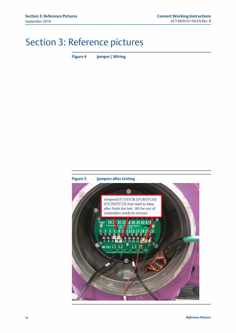
A) Only keep jumper STC7/STC9, STC8/STC10, STC20/STC22. The remaining jumpers needs to remove for next test unit.
B) Print the report from database. (fill in the CCM/LDM/APD firmware rev.)
C) Ship the unit.
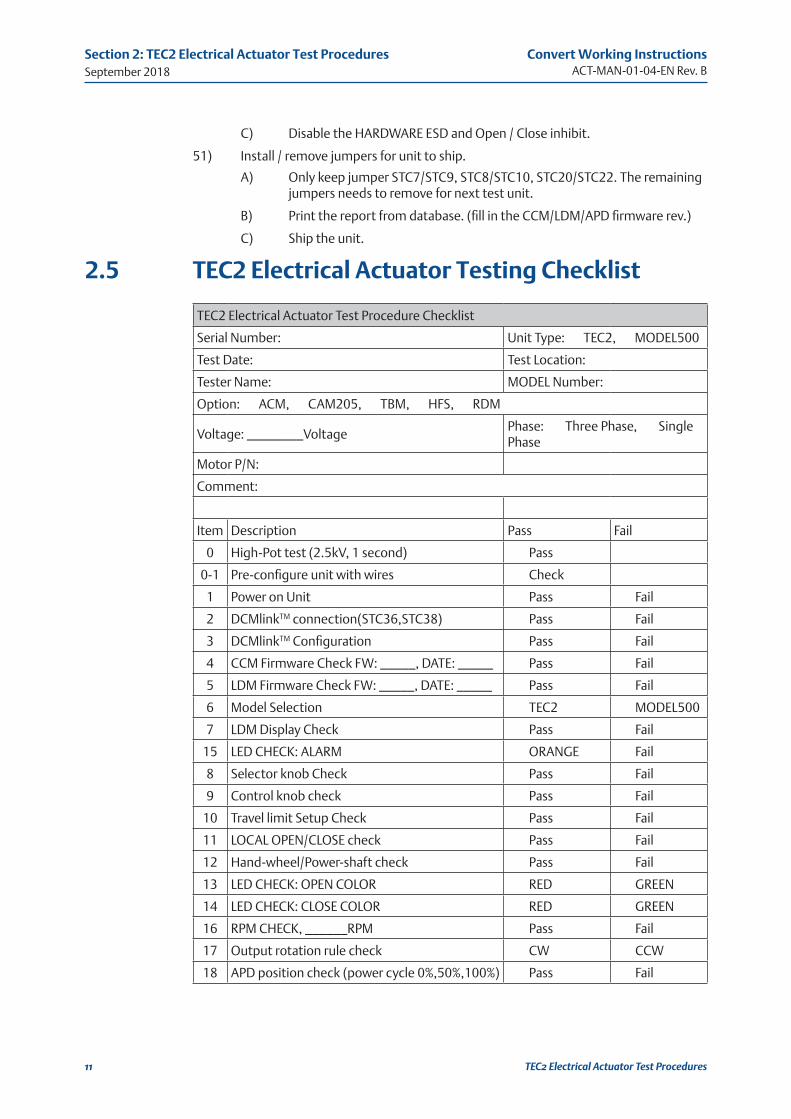
2.5 TEC2 Electrical Actuator Testing Checklist
TEC2 Electrical Actuator Test Procedure Checklist
Serial Number: Unit Type: TEC2, MODEL500
Test Date: Test Location:
Tester Name: MODEL Number:
Option: ACM, CAM205, TBM, HFS, RDM
Voltage: ________VoltagePhase: Three Phase, Single Phase
Motor P/N:
Comment:
Item Description Pass Fail
0 High-Pot test (2.5kV, 1 second) Pass
0-1 Pre-configure unit with wires Check
1 Power on Unit Pass Fail
2 DCMlinkTM connection(STC36,STC38) Pass Fail
3 DCMlinkTM Configuration Pass Fail
4 CCM Firmware Check FW: _____, DATE: _____ Pass Fail
5 LDM Firmware Check FW: _____, DATE: _____ Pass Fail
6 Model Selection TEC2 MODEL500
7 LDM Display Check Pass Fail
15 LED CHECK: ALARM ORANGE Fail
8 Selector knob Check Pass Fail
9 Control knob check Pass Fail
10 Travel limit Setup Check Pass Fail
11 LOCAL OPEN/CLOSE check Pass Fail
12 Hand-wheel/Power-shaft check Pass Fail
13 LED CHECK: OPEN COLOR RED GREEN
14 LED CHECK: CLOSE COLOR RED GREEN
16 RPM CHECK, ______RPM Pass Fail
17 Output rotation rule check CW CCW
18 APD position check (power cycle 0%,50%,100%) Pass Fail
Convert Working InstructionsACT-MAN-01-04-EN Rev. B
September 2018
12
Section 2: TEC2 Electrical Actuator Test Procedures
TEC2 Electrical Actuator Test Procedures
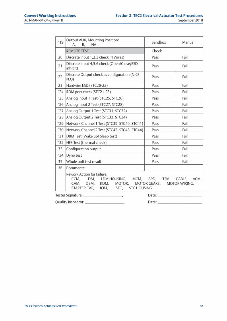
*19Output AUX, Mounting Position: A, B, NA
Sandbox Manual
REMOTE TEST Check
20 Discrete input 1,2,3 check (4 Wires) Pass Fail
21Discrete input 4,5,6 check (Open/Close/ESD inhibit)
Pass Fail
22Discrete Output check as configuration (N.C/N.O)
Pass Fail
23 Hardwire ESD (STC20-22) Pass Fail
*24 RDM port check(STC21-23) Pass Fail
*25 Analog Input 1 Test (STC25, STC26) Pass Fail
*26 Analog Input 2 Test (STC27, STC28) Pass Fail
*27 Analog Output 1 Test (STC31, STC32) Pass Fail
*28 Analog Output 2 Test (STC33, STC34) Pass Fail
*29 Network Channel 1 Test (STC39, STC40, STC41) Pass Fail
*30 Network Channel 2 Test (STC42, STC43, STC44) Pass Fail
*31 DBM Test (Wake up/ Sleep test) Pass Fail
*32 HFS Test (thermal check) Pass Fail
33 Configuration output Pass Fail
*34 Dyno test Pass Fail
35 Whole unit test result Pass Fail
36 Comments:
Rework Action for failure:CCM, LDM, LDM HOUSING, MCM, APD, TSM, CABLE, ACM, CAM, DBM, RDM, MOTOR, MOTOR GEARS, MOTOR WIRING, STARTER CAP, IOM, STC, STC HOUSING
Tester Signature: ___________________, Date: ______________________
Quality inspector: ___________________, Date: ______________________
September 2018
Convert Working InstructionsACT-MAN-01-04-EN Rev. B
13
Section 3: Reference Pictures
Reference Pictures
Section 3: Reference picturesFigure 4 Jumper / Wiring
Figure 5 Jumpers after testing

For complete list of sales and manufacturing sites, please visit www.emerson.com/actuationtechnologieslocations or contact us at [email protected]
World Area Configuration Centers (WACC) offer sales support, service, inventory and commissioning to our global customers. Choose the WACC or sales office nearest you:
NORTH & SOUTH AMERICA 19200 Northwest FreewayHouston TX 77065USAT +1 281 477 4100
Av. Hollingsworth 325 Iporanga Sorocaba SP 18087-105BrazilT +55 15 3413 8888
ASIA PACIFIC
No. 9 Gul Road#01-02 Singapore 629361T +65 6777 8211
No. 1 Lai Yuan RoadWuqing Development AreaTianjin 301700P. R. ChinaT +86 22 8212 3300
MIDDLE EAST & AFRICA P. O. Box 17033Jebel Ali Free ZoneDubaiT +971 4 811 8100
P. O. Box 10305Jubail 31961Saudi ArabiaT +966 3 340 8650
24 Angus CrescentLongmeadow Business Estate East P.O. Box 6908 Greenstone 1616 Modderfontein Extension 5South AfricaT +27 11 451 3700
EUROPE
Holland Fasor 6Székesfehérvár 8000HungaryT +36 22 53 09 50
Strada Biffi 16529017 Fiorenzuola d’Arda (PC)ItalyT +39 0523 944 411
The contents of this publication are presented for information purposes only, and while every effort has been made to ensure their accuracy, they are not to be construed as warranties or guarantees, express or implied, regarding the products or services described herein or their use or applicability. All sales are governed by our terms and conditions, which are available on request. We reserve the right to modify or improve the designs or specifications of our products at any time without notice.