Embed Size (px)
Citation preview

MM..AA..HH..II..
TTEECCHHNNOOLLOOGGIIEESS
TTEECCHHNNOOLLOOGGYY
Florida Institute of Technology
DMES: Naval Architect Design Team 150 W. University Blvd, Melbourne, FL 32901
Final Report Prepared For: Dr. Steven Wood, Senior Design Advisor
Prepared By:
Kevin Donnelly, Makemba McGuire, Andrea McAllister and Linzy Quandt

- 2 -
22 July 2008
Design Team 4 M.A.H.I Technologies Department of Marine and Environmental Sciences Florida Institute of Technology 150 W. University Melbourne FL 32901 Dear Dr.Wood, Attached is the final report for our naval architecture design project. Our team, M.A.H.I. Technologies, is creating an innovative hull design for a standard displacement hull called D’M.A.H.I Mahi. This model will built from the ground up and tested against a control hull with no design alterations. We began this project by researching the dimple effect, golf ball performance, displacement hulls, and fluid mechanics. Our research has provided excellent assistance in understanding the mechanics behind fluid motion and how to model a prototype vessel proper set up. In completing this project we feel as though we have gained a deep understanding of these subjects. The following report contains detailed information about the background, theories, designs, and testing methods of our project. It also provides information regarding purchases, budget, timeline, results, and conclusions. At this point results have been inconclusive but suggest potential success arousing further investigation. The project is at an excellent position as we continue to more forward. If you have any questions, please do not hesitate to contact us. Sincerely,
Kevin Donnelly Makemba McGuire Andrea McAllister Linzy Quandt

- 3 -
Executive Summary
On January 7th, 2008, we began our senior design project. Over the course of the semester,
our team has been researching and creating preliminary designs for this experiment. Our
main goal is to build working ship models from scratch. We have met with members of the
department and created design, building, and testing methodology. Our initial budget of
$1,250 has increased to $3,800.
The scope of this project is to study the effects on drag, created by a 191 foot coastal
carrier, through hull modification. Using both computational fluid dynamics as well as field
tests, we intend to prove that D’M.A.H.I Mahi design is more efficient than the current
standard displacement hull.
All results thus far have been inconclusive. Since construction is complete and research still
supports our theories, further investigation on the subject is to be made. Conclusive data
will either validate or dismiss our concept design.

- 4 -
III. Table of Contents
I. Title Page
II. Letter of Transmittal
III. Executive Summary
IV. Table of Contents
V. Acknowledgements
VI. List of Figures
VII. List of Tables
VIII. Introduction
a. Motivations
b. Objectives
c. Organization
IX. Background
a. Historical
i. Golf Balls
ii. Displacement Hulls
b. Basic Theory
i. Naval Architecture
X. Procedures
a. Engineering Specifications
b. Computer Models and Analysis
i. Pro Surf
ii. Pro Engineer
iii. Fluent
c. Construction of the Physical Models
d. Testing
e. Budget
f. Safety and Precautions
XI. Results
XII. Discussion
XIII. Conclusion
XIV. Recommendations
XV. References
XVI. Appendices

- 5 -
Acknowledgements
M.A.H.I Technologies Design Team would like to thank all those who have taken
part in this project. The computer modeling, research, and testing that we
performed raised many questions and without assistance, we would not have made
it this far. We would like to recognize Dr. Steven Jachec, Dr. John Sainsbury, Dr.
Steven Wood, and Alan Shaw for their knowledge and support throughout this
project.
We also appreciate all material, labor, and monetary donations we have received.
With out the extra assistance, this project would not be possible. For this we would
like to recognize Dr. Steven Jachec for providing us with addition grant funding from
Florida Institute of Technology, Eric Rohl of Structural Composites Inc. for donating
over twenty hours of CNC labor for our plugs, and Dave Catino for allowing us to run
tests using his facility at Regal Marine Industries.

- 6 -
List of Figures
Figure 1- Featherie
Figure 2- Gutties
Figure 3- Flow Patterns of a Fluid Around a Sphere
Figure 4- Aerial View of Moving Vessel
Figure 5- Displacement vessel
Figure 6-NURB
Figure 7- Attempt one: Rendered View
Figure 8- Attempt one: Right View
Figure 9-Polyline Mesh
Figure 10-Surfaced
Figure 11-Shaped
Figure 12- Gaussian Surface
Figure 13- Pro Engineer Rendered Concept Hull
Figure 14-Patterned Revolve Cut
Figure 15-Dimples in Concept Hull
Figure 16- Whole Concept Hull Dimpled
Figure 17-Fluent Screen Shot 1
Figure 18- Fluent Screen Shot 2
Figure 19-Fluent Screen Shot 3
Figure 20-Makemba and Linzy using the Hot Wire Cutter
Figure 21-Removing First 3 inch Section
Figure 22- CNC Machine at Structural Composites
Figure 23-Plug Coated in Epoxy Resign
Figure 24-Sterm of Model Coated in Epoxy Resign
Figure 25-Sanding Down Thick Spots of Epoxy Resign
Figure 26-Applying Bondo to Plug
Figure 27-Applying Primer and Wet Sanding Plug
Figure 28-Applying Mold Release Agents
Figure 29-Spraying on the PVA
Figure 30-Applying the Tooling Gel Coat
Figure 31-Trimming the Flange
Figure 32-Tryng to Release the Plug from the Mold
- 7 -
Figure 33-Pulling Out the Plug
Figure 34- Fiberglass Laid in the Mold
Figure 35- First Part Released from the Mold
Figure 36- Final Control Hull Model
Figure 37- Test Tank Facility at Regal Marine Industries
Figure 38-Actual Test Tank and Towing Beam Used for Experiment
Figure 39- Metal hook for Towing Mechanism
Figure 40-S-Type Load Cell
Figure 41- Data Logger for Load Cell
Figure 42- R-232 to USB Cable
Figure 43-Screen Shot of HyperTerminal
Figure 44- Model and Towing Mechanism Set up
Figure 45- Trial 1 Data from Control Hull Model Test
Figure 46- Trial 3 Data from Control Hull Model Test
Figure 47- Trial 3 from Concept Hull Model Test
Figure 48- Trial 10 from Concept Hull Model Test
Figure 49- Photo Capture 1 from Control Hull Model Video
Figure 50- Photo Capture 2 from Control Hull Model Video
Figure 51- Photo Capture 1 from Concept Hull Model Video
Figure 52- Photo Capture 2 from Concept Hull Model Video
Figure 53- Photo Capture 3 from Concept Hull Model Video

- 8 -
List of Tables
Table 1-Vessel Particulars
Table 2-Half Ordinates

- 9 -
Introduction
Motivations
As a group interested in Naval Architecture, our main goal for this project was to
design and construct a boat from scratch. Our interests lied primarily with the
building process required to produce a fiberglass vessel. Needing a reason, we
developed a theory that states; if the principles that make a golf ball travel further
than a smooth ball are applied to displacement hull, we could potentially reduce the
drag and increase the efficiency of the vessel.
Objectives
Our objective was to modify the hull of a 191 ft costal carrier in the same way a golf
ball is modified from a smooth ball. Utilizing CFD, we attempted to model multiple
concept designs and conclude which dimpling pattern best reduces drag by
reattaching flow. Both the concept and standard designs were created into physical
models using fiberglass construction materials for in water field testing. Conclusions
were made on the effects of dimpling and its relationship to drag and efficiency.
Organization
With only four group members organization was essential. Each group member had
taken responsibility for specific areas throughout the project. Information acquired

- 10 -
as individuals was then passed on to the entire group. Linzy was responsible for
background information, paperwork, and testing. AJ was responsible for safety
management and weekly reports. Kevin was responsible for computer modeling and
budget. Makemba was responsible for CFD analysis. All group members contributed
towards construction.
Background
Golf Balls
In 1456 A.D. in Scotland the first game of golf was played and like all games, it
developed and soon its impedimenta became improved. It is
believed that the first golf balls were made out of wood. As the
game developed, the “Featherie” was invented in 1618. This ball
consisted of tightly packed into cow hide that was formed into a
sphere when wet. Unfortunately, this ball was expensive and was not affordable by
the masses. So by 1848 a new golf ball was developed, the “Guttie.” With a
completely new approach, the Guttie was created from a rubber like sap from the
Gutta tree found in the Tropics. When the rubber was
heated, it could easily be molded into a perfectly round
sphere with a nice, smooth surface. This ball was easily
produced, and easily fixed by simply reheating. At first it
seemed like a great new design. However, golfers soon
realized that it did not travel as far nor soar through the air as well as the Featherie.
Fig. 1-Featherie
Fig. 2-Gutties

- 11 -
Overtime, golfers discovered that the old, battered Gutties began to perform as the
Featherie had. Post 1880, the newly manufactured Gutties were seen with a variety
of patterns on the surface in an attempt to recreate the distance characteristics of
the Featherie. It is during this revelation, that the first signs of dimpled golf balls
were seen.
As the industrial revolution carried on, machines and molds were developed which
allowed for mass production of Gutties. The first notable pattern as called the
“Bramble” and consisted of raised spheres as visible in Figure 2. As the handcrafted
ball came to an end, more and more patterns were tested. In 1905, the modern day
dimple pattern was designed by William Taylor. Like the scaring on the balls, the
dimples serve to alter the surface of the ball and therefore change the direction of
the air around the golf ball. Scientists refer to this anomaly as the dimple effect. To
understand why the dimple effect increases the travel of the golf balls, one must
understand a bit of fluid mechanics.
As a fluid such as air contacts a sphere, the fluid bends around the sphere while
remaining in contact with the surface. However, the fluid does not remain in
contact with the entire surface of the sphere. A fluid such as air or water
surrounding any object can only do so for a given amount of time until it separates
from that body. The location where the fluid breaks contact with the surface is
called the point of separation. Figure 3, B and C, illustrate this concept with respect
to a smooth surfaced spherical object. Notice that the point of separation occurs at

- 12 -
or near 90° from the stagnation point. Figure 3A illustrates this concept with respect
to a rough surfaced spherical object, such as a golf ball.
Fig. 1- Flow Patterns of a Fluid Around a Sphere
As the air travels over a smooth ball, the flow is laminar. Comparatively as it travels
over a dimpled ball it becomes turbulent. One may assume that a turbulent
boundary layer would result in more friction and hence ebb the balls flight.
However, as the skin surface friction is increased the dimples serve to reattach the
air on to the ball for a longer time. In turn, the point of separation moves to a
location about 135° from the initial point of contact as shown in Figure 3A.
As you further examine Figure 3, you can actually compare images B and C to flow
around a displacement hull. This is because water and air both behave similarly, and
the shape of a displacement hull is similar to the curvature of a golf ball. If you look
at a moving vessel from above as in Figure 4, you will see a similar pattern created in
the water near the stern of the vessel as you see behind the spheres. The rough,

- 13 -
bubbly water you’re observing is caused from the eddies projected from the point of
separation as shown in Figure 3B.
Fig. 2- Aerial View of Moving Vessel
It is for this reason that we believe the same concept of the dimple effect used on a
golf ball can be applied to a displacement hull.
Displacement Hulls
Generally speaking, there are two distinct hull forms: planning and displacement.
Planning hull designs are used for
high speed craft and also your
common recreational watercraft.
Their general hull shape has a sharp
bow and box like stern. There is
really no significant curvature to the
design. Without the curvature, there is no point of separation that occurs on the
hull. The water separates from the vessel when the hull ends. This does not provide
us with any surface area on the hull behind the point of separation where we can
Fig. 3-Displacement Vessel

- 14 -
attempt to reattach the flow. This is why we chose not to model a planning hull.
However, a displacement hull has a rounded tear drop shape from bow to stern. As
previously mentioned, this apparent curvature allows use to apply the same dimple
effect that is used on a golf ball on a displacement hull model. A displacement hull
is a very common hull form and is used for the majority of large shipping vessels
such as freighters, tankers, and cargo carriers. The design of displacement hulls
allows for the most efficient, long distance, safe travel at this present moment. The
defining characteristic of a displacement hull is that the weight of water displaced is
equal to the weight of the ship. As a result and due to Newton’s 3rd Law, the water
provides an opposing upwards thrust while traveling at varying speeds or while
resting. However, it is important not confuse this with hydrodynamic lift which
means it does not lift out of the water as speed increases. The ship is actually
experiencing hydrostatic support corresponding to Archimedes principle. That
supports why this hull formation is generally heavy and not designed for high
speeds. Consequently, these vessels are very seaworthy because they move
through the water rather than on top of it. As a displacement hull vessel moves
through the water in a plowing motion, it is the actual hull design doing most of the
work. The engines in displacement hull vessels are quite small compared to the size
and weight of the ship. The amount of power being provided by the engine has no
significant effect on the speed of the ship. In fact, the determining factor in the
maximum hull speed of a displacement hull vessel is determined by the square root
of the waterline length. Also the waterlines, or drafts, must indicate the ships

- 15 -
loading condition. This means that the weight of the ship is established equivalently
for a given loading condition. These are the markings that you can see on the bow
and stern of displacement hulls. As you add more power to these vessels the speed
will not increase. Instead, you will only burn more fuel and cause cavitations. The
requirement for only small engines to propel such large ships is what allows these
vessels to be ideal for traveling long distances. Another benefit of require small
engines is that it frees up interior space providing a greater capacity of material for
transport.
However they are extremely slow and as previously presented even at the maximum
power the speed and efficiency leaves a lot to be desired. Although they may be
the most efficient for their tasks right now, we feel there is room for improvement.
Since the hull design does most of the work for these vessels, we think that
improving the hull design in the best way to increase the efficiency. By applying the
theory of the dimple effect and actually designing a displacement hull with dimples,
we believe we can reattach flow, reduce drag, and increase efficiency. With the
current energy crisis the world is facing, fuel efficiency is becoming the new focus of
many innovative designers. Increasing the efficiency of one of the most used forms
of trade and transportation could have major positive economical and
environmental effects. It is for the reason that we feel if this project yields
conclusive results we may have made a significant discovery and cutting edge
design.

- 16 -
Naval Architecture
The principle of using small models to test large ideas has been in existence for quite
some time. However, many attempts to use models have not been successful. It is
important to ask “with what degrees of accuracy does the model represent the
behavior of the larger prototype?” This question reiterates the importance of the
model size and technique of tank testing. For this reason, we used an existing lines
plan to create the 3D computer model of a displacement hull from which our actual
fiberglass models would be created. Models of varying sizes but identical shapes are
known as “similar models.” However, it is not only the shape that determines the
type of vessel. Modeling a 191’ Coastal Carrier involves much more than making it
the same shape, but rather have comparable theoretical values. The important
value that we focused on for this experiment was the 18 foot water line. All of the
computer analysis we complete was focused on the 18 foot water line. In order to
have our models float at the 18 foot water line, we had to sink the vessels down by
using sand bags and make the boats weigh 135 pounds. Another value that we
compared was the maximum velocity that can be experienced by a displacement
hull. The standard formula is 1.34xlength of the loaded water line. For our model,
this equals 5.9 feet per second.

- 17 -
Procedures
Computer Models and Analysis
ProSurf 3
A product of New Wave Systems, Inc., ProSurf 3 is a three dimensional surface modeling
program specific to hull rendering and fairing. Like many surfacing programs, it uses NURBs to
create complex surfaces. Stephen M. Hollister, founder of New Wave Systems, Inc. defines
NURBs and their history as, “…Non-Uniform, Rational, B-splines. They are equations used to
define curves or surfaces that simulate the designer's batten in terms of stiffness and
continuity. In the early 1970's, 'B' or Basis splines were created (There are an infinite number of
splines.) as a convenient way to define smooth curves and surfaces interactively on the
computer screen. Rather than have a curve pass through a set of points, like ducks on a batten,
a B-spline creates a curve which is "influenced" by the positions of defining points called
vertices (see figure below). The designer changes the shape of the curve by changing the
positions of the defining vertex points.”
Fig. 4-NURB

- 18 -
The equation used to create a NURB is as follows,
P(i,j) Matrix of vertices: nrows=(k1+1) ncols=(k2+1)
W(i,j) Matrix of vertex weights: one per vertex point
bi(s) Row-direction basis or blending polynomial functions of degree M1
bj(t) Column-direction basis or blending polynomial functions of degree M2
s Parameter array of row-direction knots
t Parameter array of column-direction knots
The use of NURBs allow for the creation of complex surfaces, like the hull of a vessel.
Understanding the function and limitations of NURB surfaces allows the end user to
create accurate models. Fairing allows the user to create models accurate enough
for use in construction. By outputting lines characterizing the second derivative of
the surface, the program locates unwanted points of inflection. In other words, the
program highlights and magnifies any bumps or wiggles in the surface so the user
can eliminate them if so wanted. This allows for the achievement of the smoothest

- 19 -
surfaces possible while maintaining the desired shape. ProSurf 3 will be used to
create the 3D model of our boat hull.
Lines Plan:
To ensure the vessel designed was truly a displacement hull, it was based on the
lines plan of a displacement hull provided in the appendix. This eliminated the
possibility of unexpected error due to improper vessel characteristics. The vessel is a
costal carrier baring the design dimensions found in Table 2.
L.B.P 191 ft. Breadth Molded 34 ft.
Draft Molded 13.5 ft. Depth Molded 20 ft.
Molded Displacement 442.5 tons Extreme
Displacement
446 tons
Table 1-Vessel Particulars
Control Design with ProSurf 3:
A three dimensional model of the vessel is to be created, using ProSurf 3, for later
use in Fluent and Gambit. This model will provide the means necessary to determine
the characteristics of the vessel (coefficients of drag, area of separation, etc.) that
can then be compared to our concept designs. Defining the standard boat hull as our
control allows us to compare the results produced by our concept designs to make
conclusions. Accuracy in the model is top priority. Any imperfections at this point in

- 20 -
the design would provide a source of error for the entire project. These models will
also be used to create the tool paths required for CNC. Any imperfections here
would necessitate hand faring later when using foam plugs to create molds.
To create a 3-D model from a lines plan the half ordinates must be determined. The
lines plan provided contained no scale so one was created. Since the vessel is 191 ft
between perpendiculars, this means each ordinate represents 19.1 ft. The measured
distance between each ordinate was 2.85 cm. A simple ration would yield,
ftcm
ftcm
701754.61
1.1985.2
In other words, each centimeter measured on paper is equal to 6.701754 ft. This
makes 6.701754 ft/cm the scaling factor for the lines plan.
The half ordinates at each waterline were measured. The results were recorded in
Table 3 on the following page.

- 21 -
Ordinate (ft) Water lines
2 ft 4 ft 6 ft 12 ft 18 ft
A n/a n/a n/a 0.670175 6.701754
0 n/a n/a n/a 3.685965 8.71228
0.5 0.670175 1.005263 1.34035 8.042105 12.3982
1 2.345614 3.685965 5.696491 11.39298 14.07368
1.5 4.691228 6.701754 8.712281 13.40351 14.74386
2 7.707018 10.05263 11.72807 14.60983 15.41404
3 13.40351 14.74386 15.41404 15.74912 16.08421
4 15.07895 16.08421 16.08421 16.08421 16.4193
5 15.41404 16.4193 16.4193 16.4193 16.4193
6 15.07895 16.08421 16.08421 16.4193 16.08421
7 13.06842 14.40877 14.94491 15.74912 16.08421
8 8.846316 10.72281 11.39298 13.40351 14.74386
8.5 6.031579 7.707018 8.712281 10.72281 12.73333
9 3.350877 4.691228 5.361404 7.036842 10.05263
9.5 0.804211 1.541404 2.010526 3.350877 6.031579
10 n/a n/a n/a n/a 1.340351
Table 2-Half Ordinates
First Attempt
The initial attempt in designing the 3-D model had each waterline and ordinate
defined as a row/column. Each waterline was fixed horizontally on the x-y plane;
therefore each line representing a waterline would bare the same z-coordinate.
Each ordinate was fixed vertically on the y-z plane; therefore each line representing
an ordinate would bare the same x-coordinate. The points created by the

- 22 -
intersection of the rows and columns were moved to the positions of the half
ordinates. The program then creates the symmetric counterpart.
This method yielded many errors. Ordinates A, .5, and 10 were unable to be created
because they did not cross every waterline. This can be seen by the values not
available in the chart above. The program would not allow for the creation of a fixed
vertical line that did not pass through all horizontals. This left portions of the bow
and stern misshaped because the associated half ordinates could not be entered.
This can easily be seen in Figure 7.
Fig. 5- Attempt one: Rendered View
In addition, due the functionality of NURB’s, the round bilge design of the vessel was
severely deformed. This can be seen in Figures 7 and 8 very clearly. In an attempt to
correct these deformities, additional row/columns were added. By altering the Surf

- 23 -
around the imperfection, the user can sometimes corrects what the computer
outputs. After many hours of alteration, success was not achieved.
Fig. 6- Attempt one: Right View
Second Attempt
The second attempt differed from the first attempt in that it did not start with a
Surf, but rather the Surf was created. Attempt one tried to alter an existing Surf into
the desired specification of our coastal carrier. Here, a three dimensional model of
the boat was created using polylines. These polylines would be used to define the
surface, creating the Surf. This is a process known as Reverse Engineering. The
program, normally used for free lance designing, is being used to create something
that is already been designed.

- 24 -
To start, the keel was defined on the x-y plane at z=0 with its after most point at the
origin. Waterlines were then added individually. Each waterline contained the same
number of points as ordinates it did cross. The x, y, and z values for each point were
then defined as seen in Table 3. These points were originally defined as knuckles,
but were CurveFit for smoothness. With Snap ON activated, the ordinates were then
drawn by connecting points of common x value. Again, the program creates the
symmetric counterpart. The resulting 3-D mesh can be seen in Figure 9.
Fig. 7-Polyline Mesh
The next step in this process is to use the created mesh to define the surface. This
was done with the Skin/Loft Surf feature. The order and direction in which curves
are selected for skinning changes results. Originally, waterline curves were selected,
starting with the deck line and ending with the keel. This resulted in an extremely
similar outcome as attempt one, the rounded bilge of the boat being severely
deformed. This selection order was disregarded.

- 25 -
Next, ordinate curves were selected from bow to stern. Since some ordinate curves
shared points with other curves (A, .5 and 10), the Skin/Loft Surf tool would try to
skin the same point more than once. This would create bow ties in the NURB’s, in
turn creating holes in the defined surface. Although this was still a problem, the
rounded bilge was no longer an issue.
After technical support from New Wave Systems it was recommended that the
mesh be surfaced from bow to stern, but not including the curves creating the
problems. The next step would be similar to what a lofts man does on the loft floor,
to interpret the shape of the bow and stern based on the information at hand. The
three dimensional polyline mesh would provide a reference when shaping the bow
and stern. Figure 10 shows where the blue surface needed to be shaped to meet
the green curves and to eliminate any imperfections, like the ones found towards
the stern. This step was essential in developing an accurate model.
Fig. 8- Surfaced

- 26 -
Additional columns were added in the bow and the stern to allow for shaping.
Utilizing the different views in the program made it easier to shape the surface to
that of the polyline mesh. After many hours of shaping, Figure 11 shows how the
blue surface now very closely matches the shape of the green mesh, unlike in Figure
10.
Fig. 9-Shaped
The final and most time consuming step in creating an accurate 3-D model is the
fairing of the hull. K-curves were activated for each horizontal line. The K-curves
were then faired with a K-scale factor of 25. The vertical lines were faired next. This
was performed for all lines in both the Back and Bottom views. This process was
then repeated several times to achieve the smoothest hull possible. Figure 12 is a K-
patch Gaussian surface of the final computer model. Shades of blue represent
smooth surfaces while shades of yellow and red represent less smooth surfaces. The
least smooth surfaces exist where the most shaping occurred. These are also the
areas where the most fairing was required.

- 27 -
Fig. 10- Gaussian Surface
Pro Engineer
Pro Engineer is in many ways the mechanical engineering equivalent of ProSurf.
Where ProSurf is capable of modeling hulls, ProE is capable of modeling various
mechanical elements. In the Case of the Mahi mahi, one may wonder the purpose
of using Pro E? Due to its difference and greater bevy of design tools, Pro E allows us
to alter the design of the “ProSurf hull” to add the most import analysis element, the
dimples on the hull. The true purpose of the final analysis is to assess the efficiency
of a dimpled hull compared to a standard displacement hull. Therefore the purpose
of Pro E is to add the dimples in various arrangements on different hull prototypes
for further analysis.
The surface created in ProSurf 3 was imprted into Pro E. This allowed for
modification to create the concept hulls. These hulls would then also be exported
and run through Gambit and Fluent for fluid analysis. These results would be
compared before choosing the best concept design to create a physical model.
Original thoughts had the dimple designed as a part. A hole for each dimple would
be extruded from the surface and the dimples assembled into the holes. To mimic
- 28 -
the design of a golf ball, the radius of the dimple would be 7% the radius of the
round bilge. The depth of the dimple would be 7% of its own diameter. The round
bilge having a radius of approximately 6.03 ft, the radius of the dimple would then
be .42 ft with a depth of .06 ft (7/10”). This aspect of design is subject to change in
order to achieve maximum results.
A part assembly for each dimple was decided to be very time consuming and
unrealistic. After a consult with Mr. Willard, the solids modeling instructor, it was
decided the dimple would be created using a revolve cut. This eliminated the need
to assemble each dimple to the hull while allowing it to maintain the same
dimensions. This revolve cut could then be patterned over the surface of the hull
making the entire process faster and much more painless.
After defining planes in the x,y, and z directions, the surface was thickened to allow
for revolve cuts. It was made certain that the surface was thickened inward as to not
affect the geometry of the outer hull. In order for the thicken feature to work, the
.iges file needed to be imported without its symmetric part. The full hull can be
created after modification by using the mirror part tool and assembling the two
together.
The Dimple
The vessel was to be dimpled from the greatest water line and below. Therefore, a
datum point was created on the surface eighteen feet above the keel. A datum axis

- 29 -
was then created through that point and normal to the surface. An additional plane
was created that traveled through the axis and normal to x-y plane. Drawing a line in
this plane and projecting it onto the surface allowed the edge of the surface to be
used in the sketcher. Now existing on this plane was the defined edge and an axis
normal to the surface. These two items used in the sketcher allowed for the creation
of a shallow disc, baring the dimensions of the dimple, normal to the surface. This
sketch would be used to revolve cut the dimple.
Figure 13: Pro Engineer Rendering of Concept Hull
The revolve cut was made using the internal sketch above. The axis of revolution
was the normal axis created through the datum point. The remove material feature
was used to cut the dimple into the solid surface. Since a flat disc cannot be carved
into a curved surface, it was necessary to extend the geometry of the sketch beyond
the edge of the surface in order to ensure material would be removed in areas of
greater curvature.

- 30 -
Patterning: First Attempt
This revolve cut then needed to be patterned along the complex surface of the hull.
To accomplish this, a curve was drawn for the pattern tool to follow. The curve was
made by projecting a straight line, drawn on the x-z plane, onto the surface. The
projected line needed to be a sketch to be used in the pattern tool. Therefore, a
plane was defined through the projection. On this newly created plane, the use edge
tool in the sketcher then made the projection into a sketch. The earlier made
revolve cut was then fill patterned along the curve created by the projection. The
results can be seen in Figure 13. Please be aware that Figure 13 does accurately
represent the size and depth of the dimple. It is only the outcome of trying to
achieve the proper results before doing so with the correct dimensions.
Fig. 14-Patterned Revolve Cut
It can be seen that the diameter and depth of the dimples does not remain constant.
This problem spawns from the patterning of the revolve cut. The initial revolve cut
was made normal to the surface. The axis of revolution for the patterned dimples
remain parallel to the original revolve cut. This means that as the surface changes

- 31 -
shape, the revolve cuts are no longer normal to the surface like the original,
resulting in dimples with inconsistent diameters and depth.
Patterning: Second Attempt
In order to create dimples of more consistent size and shape, a fill pattern was used
using an internal reference. This reference was simply a horizontal line on the x-z
plane at the eighteen foot water line. The program was then told to space the
members along a curve, i.e. follow the internal reference line, at a spacing of 1.68 ft.
This spacing was chosen because it left one diameter of space between features. By
selecting the “follow surface shape” option in the options menu and selecting the
imported surface as the reference, the program then patterned the revolve cut
along the defined line while maintaining normality on the sketching plane. This
created normalized dimples of consistent size and shape.
In order to dimple the entire vessel, this revolve cut and patterning process was to
be repeated from the eighteen foot water line to the keel. This process came to a
halt at the ninth row of dimples when one member behaved abnormally. This
particular feature was revolved as a shell, eliminating the option to remove
material. Being a patterned feature, not an original, this member was unalterable.
After changing every option available to resolve this problem with no success, this
method had to be aborted.
- 32 -
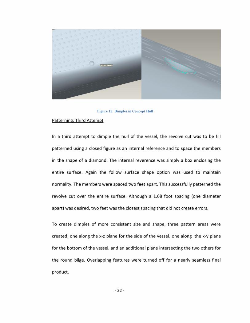
Figure 15: Dimples in Concept Hull
Patterning: Third Attempt
In a third attempt to dimple the hull of the vessel, the revolve cut was to be fill
patterned using a closed figure as an internal reference and to space the members
in the shape of a diamond. The internal reverence was simply a box enclosing the
entire surface. Again the follow surface shape option was used to maintain
normality. The members were spaced two feet apart. This successfully patterned the
revolve cut over the entire surface. Although a 1.68 foot spacing (one diameter
apart) was desired, two feet was the closest spacing that did not create errors.
To create dimples of more consistent size and shape, three pattern areas were
created; one along the x-z plane for the side of the vessel, one along the x-y plane
for the bottom of the vessel, and an additional plane intersecting the two others for
the round bilge. Overlapping features were turned off for a nearly seamless final
product.

- 33 -
Figure 16: Whole Concept Hull Dimpled
Modification of this design is a simple edit definition. Turning off any unwanted
features allows for the creation of multiple pattern layouts and multiple concept
designs. The design yielding the best analysis results will be chosen for the creation
of the physical model.
Fluent
Before any fabrication is done in a production process a fundamental step must first
be completed. This step is known as analysis; according to definition, analysis is the
examination and evaluation of relevant information to obtain the best course of
action in various alternatives. An analysis is both initial and compulsory for the
creation of a prototype the MAHI mahi is no different. Within the parameters of the
M.A.H.I. mahi, analysis is done with the use of CFD (computational fluid dynamics)

- 34 -
software “Fluent and Gambit.” This CFD; first designed in---- is an extremely
powerful software, industrially known simply as “Fluent,” it mathematically
simulates a body as it travels through a fluid, practically, this can be viewed as a
mathematical recreation of a wind tunnel.
Marine Advancement by Hydrodynamic starts with the development of the M.A.H.I
line. This line or boundary is the point at which the dimples are placed so as to trip
the boundary layer from laminar to turbulent. As one can infer the positioning of the
M.A.H.I line is imperative for the success of the experiment; Fluent allows us the
ability to insert an imaginary M.A.H.I. line, and then simulate the passage of the
water up to the 18 ft water line within a set control volume. “Fluent” can simulate
most fluids; based on the principle that a fluid is defined by its density. In the case of
this experiment, we simulate sea water across the hull of the vessel so we set the
fluid density as that of water 1000 g/m^3.
Processing using this software requires us first to design a control; the M.A.H.I mahi
is modeled after a 191 ft bp by 18 foot beam displacement hull vessel. There is no
need to expatiate on the modeling of the control since it was covered under the
previous chapter of this report. Never the less it is important to note that the
control to be built is in fact one tenth of the original vessel; however the model
being analyzed in “Fluent” is the being done so at its original operating length. While
the analyses will take longer it does give a better practical picture of a real life
displacement hull vessel. There was actually a large delay before this CFD could be

- 35 -
used, since there was a problem with the schools license; a lesson was quickly learnt
this software is very expensive and so, well protected by its license agreements.
However, when the software was finally up and kicking there was an immediate
question raised; one was inclined to wonder, judging from the actual name of the
software (Fluent and Gambit) where exactly does the Gambit fall in, and exactly how
it is related to the Fluent? One may also assume that since the program is commonly
referred to as Fluent, the Gambit side isn’t very important. Verily, this assumption,
while being a logical deduction, is actually a case of a logical progression being
entirely misleading and as a result iterating to an inaccurate response. With this
knowledge much time must be spent explaining the purpose of each of these
software pieces as they are used with regards to the M.A.H.I mahi.
“Gambit,” though rarely mentioned, is the software mesh; contrary to its less than
frequent mention it is in fact equally important or more important then “Fluent.”
The mesh is that piece of the program in which the mesh or control is actually
manipulated. The M.A.H.I. mahi was saved as an IGS file in Pro Surf or Pro E then
using the import command it was transferred unto “Gambit’s” operating screen. The
software supports many varying file types and like the IGS, it reads them all like a
group of coordinate, data points and then compiles them to the Gambit screen as an
image. Initially, in an attempt to transfer the image, the “read data” command was
selected from the file menu, but this method failed and so the method
aforementioned was employed. Once the image is successfully uploaded into

- 36 -
“Gambit,” the true power of the software can be tested. An image must be oriented
in a particular way so as to allow proper simulation, in this case fluid is expected to
flow like as the vessel would travel in water; bow to stern. As such a left to right bow
to sturn orientation was attained by simply clicking, holding and turning the vessel in
the desired direction. The image was then seen broadside, portside with symmetry
as usual created along its longitudinal center line. A control volume is the area that
one sets for the system to analyze within, if a control volume is not set, there would
be no true area at which point analysis would start and stop this could over load the
computer, as well as make results impossibly or inaccurate. It is however important
to choose a control volume, that allows for laminar, well developed flow before the
fluid actually experiences its initial boundary condition. The CV for the M.A.H.I mahi
was set at a position of 300 feet forward and aft; this gave a total of over one
hundred feet of unaffected data before the fluid actually met the fluid- vessel
boundary. The creation of the control volume is the most important step in analysis
of the vessel, and it is also the most time consuming. The mesh area can be thought
of like an infinitely graduated Cartesian plane; as such the two initial points created
are used as reference points at (+300,0,0) and (– 300,0,0). From these points a
series of points representing the vertices of a cubed surface are created. This is
easily done, however the points running across the vessel are a challenge. If we
were required to analyze the entire vessel we would build a control volume; a cube
around the entire vessel. However the M.A.H.I line and the point of separation in
turn, can only really occur on the part of the hull that is estimated to be in the water

- 37 -
at any given point in time. The 18ft vessel water mark is the highest point to which
water is expected to rise on the vessel; therefore the Gambit CV must be built so
that it only considers from keel to the 18ft waterline. One may assume that it would
make life simple if we were to draw a line from the front 300ft mark to the back –
300ft mark on the X- axis at a position of 18ft Z axis across the port side
superstructure. However the first problem started with definitions of the initial
points at (300, 0, 0) either way. To make corrections for this oversight a function
known as split line was used to create a new point at 18ft up the vertical line of the
bow. Gambit’s information tool allows for one to see the Cartesian coordinates of
points on any area on the vessel; 18ft was easy to find, and then a new point was
created as previously mentioned. The point was set on the vessel because the actual
analysis is of the vessel area itself; hence the hull must be a part of the control
volume. With this new point acquired, lines were re-drawn with the same x distance
but a different Y reference. Points located on the Z axis were placed spatially at a
distance of fourteen feet below the keel, again to allow for a well developed region.
Development of a CV is like the progression of a baby learning to walk; first the baby
learns to role, then to creep then finally and as a youngster how to walk. In gambit
we first set points and vertices as described above, then connect these points to
make lines into a cube; and last but most importantly give this cube solid faces. It is
in completing this last step that the most unique of problems arise. The broadside
area of the vessel is the reason for the entire exercise of analysis; it is the point at

- 38 -
which the dimples are located and the area we would need to analyze. It is
therefore necessary to make the broadside of the vessel a face for analysis. This may
sound simple but if the model is set as it is, fluent analysis would view the broadside
of the vessel as just the face of the cube. It is hence necessary to make the
broadside of the vessel a face in the CV; this implies that where the control volume
may have been composed of the six faces of a cube it should now be increased to
seven. However, inserting a face isn’t as easy as it sounds, we must first realize that
the broadside of the vessel exists in two dimensions; both on the z and x plains,
consequently instead of the initial guess of seven faces the new CV would have eight
faces. Splitting a face is similar to splitting a line, we select the face to be split and
then using the faces icon we select the split face command. The program requires us
to split the face on two axes as previously mentioned; so once the face is split the
new CV now comprises the rounded contours of the vessel. Gambit displays the
splitting of a face, by merging the curved line following the contours of the vessel,
with the straight line representing the rest of the control volume. It is important to
note that only one side of the CV either port or starboard could be modeled at any
given time. However Gambit allows us to circumnavigate this problem, and reduce
the work load of repeating the long exercise described above, by the reflection
command. We however do not need this fantastic command because; a vessel is
symmetric along its center line, thus data analyzed on one side of the vessel is
exactly the same as that on the opposite side. As a result of the lacking computer
power available, it is important that we reduce the amount of area that the system

- 39 -
must analyze. In keeping with this principle of reduction forced upon is by computer
constraints; when a face is split, an excess face is built by the line above the new,
split 18 ft waterline forward and aft as well as the top line created by the vessels
split face. To further clean the mesh therefore, this face must be deleted by
selecting the lines that make up its area, taking care not to delete what gambit
refers to as leading edges; lines that make the top of one face while making the
bottom of another. When this process is complete the remaining hull design is
displayed as half of a vessel cut along the bow and stern forward to aft along its 18
ft keel loaded waterline
Gambit command tools are set up so as to guide our thoughts through every step of
creating a control volume; hence the last step is actually creating a solid mesh.
Meshing is the actual process by which the program creates small nodules or shapes
inside the faces of the cube. The easiest shapes are simple squares but it is more
accurate to use tetrahedral, octahedral or polygon figures. The nodules further
divide the CV into smaller shapes for analyses; at every one of these shapes added in
by Gambit, Fluent analyses and calculates the required information. The more
populated the figure is with accurately defined nodules, the more precise the
calculations made by the software will be. It also goes to reason that the more
tightly spaced these nodules are, the less chance of error one will have in evaluating
the contours of the vessel. Logically though the more nodules that a present and the
greater the intricacy of the nodule designs, the longer it will take for Fluent to do its

- 40 -
analyses. Nodules are hence, generally selected to maintain high levels of accuracy,
as well as to produce the fastest result from fluent. The MAHI control volume as it is
uses tetrahedral shapes in its design, however these shapes are not graded; this
means they are all equally spaced through out. This design though highly accurate
takes a bit more time to analyze, so alternatively the CV could be graded with larger
spacing on the outer partitions and tighter spacing within the boundaries of the
vessel. To achieve this grading, and so circumvent the problem of limited computer
power, it is required that the lines created earlier be readjusted vertex by vertex.
Every time a mesh is built whether its nodes are of tetrahedral or square in nature,
or its mapping is wire meshed, paved or mapped/ paved every line must join at
some point. Node vertices are the points at which more than one of these lines
meets. It is because of this fact that grading becomes a tad bit tedious; picture one
face of the vessel that is tetrahedral and spaced at a distance of 5 cm apart for
accuracy, meeting the leading line of another area that is easier spaced with
quadrilaterals at a distance of 10 cm apart. As the name implies a vertex indicates
the meeting of lines, we must position the lines manually so as to get them as close
as possible to meeting each other at the most populated leading edge vertices. In
some cases, as in this case where there is a different nodal geometry, we are
required to adjust only the faces that can be adjusted while leaving the faces with
leading edge conflicts between tetrahedral and quadrilaterals alone.
- 41 -
When the CV is properly meshed about the vessel, the next step, as the Gambit tool
box cycle suggests, is the creation of boundary values. Boundaries are created so
that Fluent can have given parameters in which to perform its calculations. Not only
do these parameters have to be set, but it is of extreme importance that these
parameters be set at given points. To set the parameters the orientation of the
MAHI mahi must first be observed; bow to sturn orientation left to right on the
matrix. If the MAHI mahi is set at this angle the CV must thus be labeled and
parameterized with similar coordinates in mind. The left side of the CV acquires the
label of “in flow” and the boundary is set as a velocity input. Doing this lets Fluent
know that the velocity at this point is given and it needn’t derive a velocity at this
point, in essence the velocity is fixed. The right most portion of the CV is set as a
pressure outlet; here we must recall that we are testing for changes in velocity so
the outlet is one of pressure. The rest of the control volume except that defined by
the curve of the vessel, is also set as a pressure domain; since the area surrounding
the MAHI mahi is always governed by both Dynamic and Hydrostatic pressure. The
area of most importance is selected and labeled last; the contours of the vessel’s
hull. Fluent like most CFD programs considers any object set in a control volume a
wall. In other Fluent doesn’t see the vessel in its analyses as a boat but rather a wall
with dimples or without dimples. The control that is modeled initially is without
dimples, and the area, not yet defined from above, is set as its own pressure
boundary or domain. Fluent, hence still analyzes this area as a wall, but a wall with
limited to no set boundaries, we are unable to assume a boundary on the vessel’s

- 42 -
hull so this pressure field command allows us to cheat by defining a member of the
CV without sufficient information. The process described above is repeated for both
the meshing of the control as well as the varying dimple design and a final meshed
surface should look similar to the following figure.
Figure 17: Fluent Screen Shot 1
N.B. only the yellow half is being considered as actually present as the CV
On completion of the Gambit mesh work an “.msh” file is created. This file is saved
and then exported into Fluent at which point the numbers connected to the analysis
are compiled and calculated. Before starting Fluent running, parameters of

- 43 -
operation similar to those set up in Gambit earlier must be applied and ensured
congruent. In addition other options like initial velocity of the fluid in the control
volume and the Reynolds number of the fluid medium must also be included.
Fluent can display in many different formats, however one of the most powerful
Fluent displays is that of colour contours as illustrated in Fig# bellow the color
profile for an aerospike engine.
Figure 2: Fluent Screen Shot 2
Figure 3#: Aerospike temperature contours
Fluent uses a variation in color to articulate the changes in pressure, velocity,
Reynolds numbers and coefficient of drag in the system. A good example of color
imagery is the display given as a result of temperature changes above; the softer
colors like blues are used to represent colder temperatures while the brighter colors
like green are used to display hotter conditions. Fluent, like many other analysis
software, also uses the imagery described above to display changes in force; the

- 44 -
softer colors for lower forces and colors like red for large force displacements.
D’MAHI mahi results however are displayed initially with a different sort of imagery;
Fluent requires that in the final pre-analysis processes one selects a desired number
of iterations. It is prudent that one set an initial iteration number of some relatively
small amount; so as to see how long the program takes, and if in fact the mesh is
well enough built to convergence at all. In this case the initial number is set at 100;
below is a screenshot of the graphical result.
Figure 19:Fluent Screen Shot 3

- 45 -
On careful observation one can note that the graphs are in fact converging to some
point and that the mesh was well enough created. On the contrary, due to the
limited capacity of the computer, this mesh design while simple and ungraded, as
mentioned in the earlier half of this paper’s section on meshing, took a total of a
week to analyze. This is a terrible average considering that at least 10,000 iterations
are compulsory to get an acceptable result, and the more accuracy required the
more iterations needed. It is for this reason highlighted above, that mesh grading,
the time consuming procedure mentioned previously, must be done. Help must be
given to the weak computer so that it is capable of doing an analysis; it is clearly
evident under these circumstances that the system available to run this software is
the ebbing factor; and with the time frame available, though the mesh was graded it
is impossible to accomplish the ten thousand iterations required to give a different
result on each dimple variation. As a result the best guess at design must be used, so
as to complete the process in the stipulated time frame.
Fluent and Gambit is a powerful software package and with proper analysis it allows
us to ascertain the most efficient dimple design based on a decrease in the
coefficient of drag and a change in the velocity of the vessel due to this previously
mentioned coefficient. However for the program to function at its highest capacity
and so save time and effort, it must be supported by hardware with the aptitude to
correspond with its magnanimous analysis power. The MAHI mahi is a test design
based on a new principle of a dimpled hull to increased efficiency, because of CFD

- 46 -
analysis it should be possible to aspire to achieve Marine Advancement by
Hydrodynamic Input at its fullest without the tedium of physically testing all designs,
but rather the design that seems to function aptly according to CFD. It is however
important to note that the best design according to computer simulations is not
necessarily the best design in practice; “the proof of the pudding is in the eating;”
we must first test the vessel in real condition for true results regardless of the
assumptions based on the CFD software.
Construction of the Physical Model
Two seven foot physical models were to be created, a control and a concept, for
practical testing. Foam was to be machined using a CNC to create the plug that
would provide the platform to build the mold. From the mold, two parts (i.e. hulls)
would be pulled. One would remain unchanged, the control, and one would be
modified with dimples, the concept.
The Plug
The plug, also called the master, was machined form two pound density Polystyrene
foam. The surface file created in ProSurf 3 was used to create the tool path for
machining. To prevent the collar of the bit from destroying the finished surface
during machining it was necessary to prepare the foam into three inch thick layers.
To do this, we needed to use a hot wire cutter to insure that we had quality, level

- 47 -
pieces. The shop we are working in belongs to Alan Shaw, graciously donated much
of his time, knowledge, and facility to ensure construction was done correctly.
Figure 20: Makemba and Linzy Using the Hot Wire Cutter

- 48 -
Figure 21: Removing First 3 inch Section
After two three inch thick sections were prepared, the foam was ready for CNC. All machine
and labor hours were donated by Eric Rohl of Structural Composites Inc. Below are
photographs of the CNC at work.
Figure 22: CNC Machine at Structural Composites

- 49 -
Original plans called for the creation of two plugs, the control using the ProSurf 3
file, and the concept design from the Pro Engineer file. Unfortunately, the concept
design in Pro Engineer could not be machined using the three axis mill like the one at
Structural Composites Inc. It was then decided that one plug would be made to
produce one mold and two boats. One could be modified with dimples later.
After the foam was machined the layers were assembled with epoxy based resign
and hand faired. Since Polystyrene foam is a styrene based product it can not come
in contact with liquid based styrene products. This includes Polyester resigns, gel
coats, and solvents. For this reason epoxy based resign was used in direct contact
with the foam. A slurry of epoxy resign and micro balloons was applied to the
surface of the plug to protect the foam from exposure to styrene based substances.
One layer of 6 oz fiberglass sheet was followed by the epoxy and glass bubble slurry
to provide rigidity, protecting the foam from dings and dents. This process can be
seen in the images below.

- 50 -
Figure 23: Plug Coated in Epoxy Resign
Figure 24:Stern of Plug Coated in Epoxy Resign

- 51 -
After curing, any areas of overlapping fiberglass were ground smooth. The textured
surface of the fiberglass was then filled using a thick slurry of epoxy resign and micro
balloons. After fully curing, this filler coat was sanded smooth.
Figure 25: Sanding Down the Thick Spots of Epoxy Resign
A single coat of Urethane primer was applied to the surface revealing small imperfections in
the plug. High spots were then sanded down and low spots filled with Evercoat lightweight
body filler. Body work was complete when the surface was sanded smooth.
Figure 24: Applying Bondo To Plug

- 52 -
Four heavy coats of Urethane primer were sprayed on the master covering body
work and sanding scratches. To ensure the smoothest surface possible, the primer
was wet sanded with 600, 1000, and then1200 grit wet sanding paper.
Figure 27: Applying Primer and Wet Sanding Plug
The Mold
The mold, also called a tool, is the female replicate of the plug. To prevent the mold
and plug from bonding together release agents must be applied to the surface of the
plug. A minimum of three heavy coats of TR Hi-temp dry release wax were applied
and buffed off. Following wax, a minimum of six coats of PVA, Poly Vinyl Alcohol,
were applied using the gravity gun. Each coat was applied in a light mist fifteen
minutes apart.

- 53 -
Figure 28 : Applying Mold Releasing Agents
Figure 29 : Spraying on PVA
Tooling gel coat was then applied to the surface of the master. The entire gallon was
activated using 2 fl oz of MEKP, Methyl Ethyl Ketone Peroxide. Ideally the tooling gel
should be sprayed on 35 mils thick. Not having the tools required to do so, it was
rolled on instead.

- 54 -
Figure 30:Applying Tooling Gel Coat
After a few hours of curing the gel coat is hard enough to resist scratching. Although
tacky, gel coat will always remain tacky unless mixed with wax, the gel coat now
needed to be reinforced with fiberglass. Two layers of ¾ oz fiberglass matt were
saturated and rolled out with General Purpose Polyester resign. Layers of fiberglass
matt were applied two at a time at two hour intervals. After building eight layers of
matt, the mold was left to kick off over
night.
Once fully cured, the edge of the flange
was trimmed exposing the boundary
between the mold and the plug.
Wooden wedges were forced in the seam, creating space between the tool and the
Figure 31 : Trimming the Flange

- 55 -
master. After creating separation in the stern, water was forced into the mold. PVA,
being a water soluble product, dissolves into the water aiding in the release of the
mold.
Figure 32: Trying to Release the Plug from the Mold
After the water broke the suction created by the flat bottom of the mold, the plug
was removed, leaving behind a tool.
Figure 33: Pulling the Plug from the Mold

- 56 -
The Models
With the mold complete it was time to create the physical models. The tool first
needed to be cleaned. A quick wash with soap and water removed any excess PVA.
A gentle wipe with acetone removed any leftover residue.
Again, TR Hi-temp dry release wax and PVA were applied to the surface of the mold
in the same manner to prevent the models and mold from bonding together. 40 oz
of canary yellow gel coat, reduced 4:1 with styrene, was sprayed on to the mold.
After the gel coat has cured enough to resist scratching it was reinforced with
fiberglass. Again, ¾ oz
fiberglass matt was applied
two layers at a time at two
hour intervals.
After laying four layer of
matt, the model was left to
kick over night. The mold and
boat were then separated with wooden wedges and again flooded with water.
Released from the mold was the final product.
Figure 34: Fiberglass Laid in the Mold

- 57 -
Figure 35: First Part Released from Mold
The boat was place back in the mold and reinforced with two more layers of
fiberglass. Placing the boat back in the mold prevented the possibility of warping
during reinforcement. Cardboard tubes were fitted to the bottom of the boat and
fiberglass in. This provided rigidity for the sides of the vessel against hydrostatic
pressure. Unfinished edges were trimmed yielding a final product.
The second vessel was created in the exact same manner as the first. This boat
however was built with twelve layer of fiberglass matt in the stern to provide
enough thickness for modification. After the stern was properly thickened it was
modified with dimples. This was achieved by modifying the cutting edge of a half
inch drill bit. It was ground shallower to apply the dimples without cutting all the
way through the material. After cutting in the dimples more yellow gel coat was
sprayed on to yield a finished product.
The control vessel, the one left unmodified, was then air brushed with acrylic paint.
Since the acrylic paint is water soluble, it needed to be sealed with clear coat. For

- 58 -
this reason both boats were painted with clear coat to make the surface textures of
each boat was uniform, eliminating a potential source of error during testing.
Figure 36: Final Control Hull Model

- 59 -
Testing
Once the construction of our models was complete, the next step was to test our theory. After
much research we decided that a basic towing mechanism would be the best way to provide
motion to the vessels. By using a towing method, we did not have to create nor supply a
motor, power supply, and steering mechanism. We also saved ourselves the trouble of
calculating power input, output, efficiency and all other measurements needed to accurately
analyze motorized vehicles. We determined that by towing a model at a constant speed over a
given distance, we would be able to measure the force used to pull the boat across the tank.
Fluid mechanics tells us that the greater the drag force between the surface of the hull and the
water, the more force necessary to keep the vessel in motion. Therefore if we could actually
measure and record the force needed to keep the vessel moving at a constant speed, we would
be able to infer that when the force decreased, so did the drag and resistance between he hull
and the water. At this point, we set out to develop a testing facility/setup and force measuring
system.
The first step in planning our experimental testing was to locate a facility with a large enough
water tank and towing mechanism that we could have made available to us. We tried to stay as
near to our local community as possible, however the only facility meeting these standards was
Regal Marine Industries located in Orlando, Florida. Dave Catino, an employee of Regal Marine
Industries and also a Florida Institute of Technology Alumni, set up a preliminary meeting with

- 60 -
Figure 37: Test Tank Facilities at Regal Marine Industries
us at which time we toured the facilities and discussed a plan for our experiment as shown in
Figure 37. After viewing both the testing tanks and testing canal that they offered to us, we
decided that the testing tank would be the best option. The following photos will show the
testing tank that we chose to use for our experiment. Figure 38 gives an overview of the testing
tank. The testing tank was 50 feet long, 15 feet wide, and four feet deep. Since our models
were only seven feet long with a depth of one and a half feet, this was an ample size tank for
the experiment we would be running.

- 61 -
Figure 38: Actual Test Tank and Towing Beam Used for Experiment
At the very top of the photo you can see a horizontal, bright yellow beam that spreads across
the width of the test tank. Connected to this beam you can see a blue box-like piece of
equipment. The yellow beam is controlled by remote control and travels over the length of the
tank at a constant speed. The blue box houses the metal cable that is attached to a large metal
hook. This hook can be raised all the way up to the beam or lowered all the way down to the
surface of the water. Figure 39 provides a close of up the metal cable and hook mechanism.
This hook was used to attach the towing mechanism to the load cell that was attached to our
models. This set up will be discussed next.

- 62 -
Figure 39 :Metal Hook for Towing Mechanism
As mentioned before, the models were going to be towed at a constant speed and we were
going to measure the force necessary to do this. In order to measure and record the force used
to pull the models, we purchased an LC-210 S-Shaped Load Cell as shown bottom left.
Figure 40: S-Type Load Cell Figure 41 : Data Logger for Load Cell

- 63 -
The bottom end of the load cell was placed over a screw we had on the bow of the model. The
top end of the load cell had a piece of metal wire tied to it and then tied to the metal hook
previously shown. On the right of the load cell you can see there is a cable attached. This cable
runs to the data logger that is shown in the photo to the right of the load cell. The data logger
actually records the readings the force gauge
is experiencing four times per second. The
numbers are then displayed on the screen.
But we needed to actually record this data on
a computer so that the data could be analyzed
in excel. So to make this happen we
purchased and R-232 to USB converter cable
(shown at right) and connected the data
logger to a laptop using the com 11 USB port.
To transfer the data from the data logger to the computer, the computer need a way to “call”
the data logger and open a pathway for the data to travel. To do this we used a program called
HyperTerminal that comes standard on
modern computers. Once the data
logger and laptop are synced, you just
start at stop the transfer using the
respective commands on
HyperTerminal for each trial. The data
Figure 42: R-232 to USB Cable
Figure 43- HyperTerminal Screen Shot

- 64 -
for each trial is collected in a text file that can then be transported in Excel. From there we
would be able to graph the results and provide graphical representation of the forces
experienced by the load cell over the length of the tank.
The photograph below shows all the parts of the experiment put together. You can see the
metal hook lowered to the water, the load cell on the bow of the boat attached to the metal
hook, and the laptop and data logger off to the side of the tank. Something else that you see in
this picture is bags inside the model. These grocery bags were each filled with sand to sink the
boat down to the eighteen foot water line. By the time this process was complete, the boats
weighed 135 pounds. Now that all of the set up was completed, it was time to actually run the
experiment.
Figure 44: Model and Towing Mechanism Set Up

- 65 -
To begin the experimentation, we first had to calculate the constant speed at which the towing
mechanism was moving. To do this we simply measured the time it took for the hook to travel
a given distance. We chose a 16 foot long section in the center of the towing tank as our given
distance. This way the beam had already reached its maximum constant speed and was not
beginning to decrease in speed either. Using a stop watch, we clocked the metal hook traveling
this distance and measured a time of 35.2 seconds. Using a simple distance divided by time
equation, we calculated that the speed of the beam was 2.2 feet per second. However, we had
intended to tow the model at the maximum velocity for a displacement hull which is 1.34 x
loaded water line. Using this calculation we determined that the ideal towing speed would be
5.9 feet per second. But since this value is the maximum velocity at which a displacement hull
can travel, then it the actual towing speed of 2.2 feet per second still falls in the range of
accurate traveling speeds for a displacement hull.
Next, we were ready to run a test trial to make sure that load cell was read properly and the
data logger and HyperTerminal were properly synced and recording. Once everything was
calibrated, we were ready to begin.
Due to the block of time allotted to us to complete our testing, we were only able to complete
ten trials for each model, resulting in twenty data sets. First we ran the experiments with the
control model. The tests did not run quite as smoothly as we had intended. Since the hook up
between the models and the towing mechanism was not rigid, the models were a little hard to
control after the each trial. The models picked up so much speed and momentum, that they
actually got ahead of the hook and snapped the wire a few times. Luckily, the problems

- 66 -
occurred after the period of the tests where the section of data being analyzed was actually
recorded. We continued to observe and record each trial and accumulated enough data to
create and compare graphical representations. For example, look at two randomly selected
graphs from the control model experiments. Figure ___ is from the first trial run using the
control model. Unfortunately, we did not ever achieve a constant velocity during the test
which would be shown as a linearly across time interval. This is what we had hoped to achieve
from our testing methods. As we continued to graph the rest of the data, we continued to view
the same trend. Figure ---- shows is from the third trial run using the control model and
shows the same general pattern and Figure____. But since the towing method and facilities did
not allow the models to ever reach a constant velocity, we were forced to analyze the data we
did obtain.
Figure 45 :Trial 1 Data from Control Hull Model Test
Force- lbf
Time-sec

- 67 -
Figure 46 :Trial 3 Data from Control Hull Model Test
The first spike that you see in the graphs is portion of data that we are analyzing. The portion
of the spike with the increasing slope is actually showing the vessel as it slowly beings to move
and the force is increasing. The maximum at the top of the spike shows the maximum amount
of force necessary to bring the vessel up to speed. The decreasing slope portion of the spike
shows the vessel catching up to the hook and maintaining its own motion speed, therefore
decreasing the force need to keep the vessel moving. All the other data past the point where
the spike ends is data after the model reached the end of the tank. As we observed the waters
behavior around the point of separation and the stern of the vessel, we did not observe
anything out of the ordinary. In fact, the water behaved the same as shown in Figure 4 found in
the Background section of this report.
Force- lbf
Time-sec
- 68 -
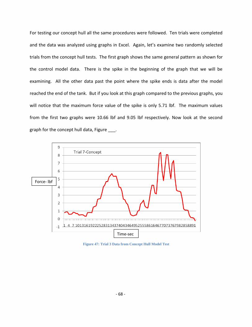
For testing our concept hull all the same procedures were followed. Ten trials were completed
and the data was analyzed using graphs in Excel. Again, let’s examine two randomly selected
trials from the concept hull tests. The first graph shows the same general pattern as shown for
the control model data. There is the spike in the beginning of the graph that we will be
examining. All the other data past the point where the spike ends is data after the model
reached the end of the tank. But if you look at this graph compared to the previous graphs, you
will notice that the maximum force value of the spike is only 5.71 lbf. The maximum values
from the first two graphs were 10.66 lbf and 9.05 lbf respectively. Now look at the second
graph for the concept hull data, Figure ___.
Figure 47: Trial 3 Data from Concept Hull Model Test
Force- lbf
Time-sec

- 69 -
Figure 48: Trial 10 Data from Concept Hull Model Test
Again, look at the maximum force experienced in this trial. It is only 6.78 lbf. Just be these
observations, we began to believe that our theory may be correct. We continued to further
analyze our results and took the average maximum forces experienced by each hull. For the
control hull model, the maximum force was 8.44 lbf. For the concept hull model, the maximum
force was 7.76 lbf. These values support our theory that our concept hull reduced drag and
resistance created between the surface of the hull and the water. Unfortunately, we did not
feel that the amount of data we have collected at that point, nor the quality, is sufficient
enough to draw a strong conclusion and deem our theory correct. However, we did believe
that this data does suggest that our theory may be correct. It is for this reason that we hope to
continue working on better testing facilities and methods so can gather significant data and
draw an accurate conclusion. The raw data and graphs for each trail can be found in the
appendix.
Force- lbf
Time-sec

- 70 -
Although the numerical data can only suggest that our theory may be correct, we do have visual data of
our observations to further support our allegations. As mentioned before, the wake of the control hull
model behaved in the same manner as expected. The point of separation was between amiship and the
stern, and the wake formed the pattern previously discussed in the history portion of this paper. The
following photos show exactly
this.
Normal Wake Pattern
Figure 49 : Photo Capture 1 from Control Model
Test Video

- 71 -
However, the really interesting visual proof comes from the screen captures of the concept hull
test videos. When we examined the videos, we noticed a very concentrated stream of water
flowing off the point of the stern as opposed to the open wake patterns observed with the
control model. You could actually see the water get sucked back in against the hull and stay
attached to until the last point on the hull. This means that you can actually see the dimples
reattach the flow which is the main goal of this project. The following photos will provide visual
explanations.
Normal Wake Pattern
Figure 50: Photo Capture 2 from Control Model
Test Video

- 72 -
Now, as you look at the above photo, you can see the concentrated stream of water. Notice
how the stream of water generates from the rear most point of the stern of the concept vessel.
This shows that the water is not detaching from the surface of the hull as it travels over the
stern. It is not detaching until there is no longer any hull surface to travel across.
Concentrated Stream of Water
Figure 51 : Photo Capture 1 from Concept Model
Test Video
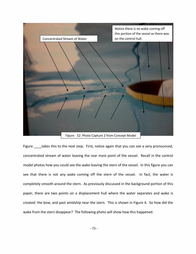
- 73 -
Figure ____takes this to the next step. First, notice again that you can see a very pronounced,
concentrated stream of water leaving the rear most point of the vessel. Recall in the control
model photos how you could see the wake leaving the stern of the vessel. In this figure you can
see that there is not any wake coming off the stern of the vessel. In fact, the water is
completely smooth around the stern. As previously discussed in the background portion of this
paper, there are two points on a displacement hull where the water separates and wake is
created: the bow, and past amidship near the stern. This is shown in Figure 4. So how did the
wake from the stern disappear? The following photo will show how this happened.
Concentrated Stream of Water
Figure 52: Photo Capture 2 from Concept Model
Test Video
Notice there is no wake coming off
this portion of the vessel as there was
on the control hull.

- 74 -
Again, in this photo notice the same characteristics of the water previously discussed. But this
photo points out the next observation in this process. In this photo you can actually see curved
flow of water behind the standard point of separation you would find on our control model.
Also notice that there isn’t any wake detaching from the hull in this area. In fact, if you look
closely you can see that the wake you’re observing does not generate from the rear portion of
the hull shown. The curvature of the wake near the bottom right corner of the photo suggests
that the wake generate much further forward from the vessel, possible even the bow.
Therefore, if there is no wake being generated form the rear of the hull, you can see a curved
area around the stern that appears to be the water reattaching to the hull, and there is a
Concentrated Flow of Water
Area where water is being reattached
to the surface of the hull.
Point of Separation
Figure 53 : Photo Capture 3 from Concept Model
Test Video

- 75 -
concentrated stream of water leaving the rear most point of the vessel, then we can conclude
that the water being displaced around the stern is being reattached due to the dimples on the
surface of the hull in the examined area. This means that our theory is correct, and dimples on
the stern of a displacement hull will in fact reattach the flow.
Although we are not drawing the basis of our conclusion form the numerical data because we
know it is not mathematically sound, there is still error that should be considered for the testing
portion of this project. First and most importantly, the models never reached a period of
constant velocity where we could compare linear data. This systematic error in measurement
was the greatest source of error, and is the main reason that we want to find a new testing
facility where this can be eliminated. Another systematic source of error in measurement is
the way the towing mechanism was attached to the load cell. We chose metal wire because we
believed it would have the least amount of elasticity and elongation when a force was applied
to it. However, we did not measure if there was in fact and elasticity or elongation in the wire
when a force was applied to it. This may have slightly altered the force reading on the load cell.
Also, since neither the load cell nor metal hook were rigidly attached, the hook and load cell
were able to swivel and turn which again may have caused discrepancies in the readings from
the load cell. The load cell and data logger also provided intrinsic systematic error. The
uncertainty in measurement in the load cell and data logger was 0.01 lbf. Since the all the
data logging was measured and recorded electronically, there was not a great source of random
human error in this experiment. We can also compute the standard deviation of the maximum
forces experienced in each trial and the averages that we calculated. The average maximum

- 76 -
force experienced in the control hull tests was 8.44 lbf with a standard deviation of 1.99 lbf.
The average maximum force experienced in concept hull tests was 7.77 lbf with a standard
deviation of 2.19 lbf. From this point we were able to calculate the percent error in each trial
by using % ox = (ox / x ) 100% [A3]. The percent error in the control hull experiment was
(1.99/8.44)100% = 23.58% error. The percent error in the concept hull experiment was
(2.19/7.77)100% = 28.19% error. These values fall very close to each other which suggest that
there was the same amount of error in each trial. This is important to know because if one trial
had a much larger source of error than the other, then we would not be able to compare the
results. Overall the percent error could be smaller, but considering all the sources of error in
the testing method we think that this is definitely an acceptable value. So overall, we do feel
that this experiment has been successful even though the numerical data should be deemed
inconclusive.

- 77 -
Budget
Total 3800.00
Spent 3793.17
Remaining 6.83
Expense Report
Purchases Quantity Price each Amount
5 gal. Hexion 6735 G.P. Resign 9 109.67 987.03
QT. MEKP Catalyst 2 11.41 22.82
1 11.00 11.00
6OZ-30" Fabric 100 3.63 363.00
3/4OZ-50" Mat 20 3.23 64.60
91 1.94 176.54
Gal PVA#10 Film 1 14.87 14.87
Gal YA541 Canary Yellow Gel Coat 4 47.73 190.92 Gal CCP 945-B-201 Cooks Black Tooling Gel 4 61.66 246.64
Can 14OZ TR-104 Hi-Temp Past Wax 1 13.06 13.06
Jump Dirve 1 78.87 78.87
Foam 8'x32"x42" 1 460.00 460.00
Fuel Reimbersment 1 74.90 74.90
Acetone 5gal 1 49.86 49.86
1gal Styrene 1 19.20 19.20
Box L latex gloves 1 7.89 7.89
Slv 5QT measuring container 1 44.50 44.50
Stir Stix 1 4.16 4.16
3" brushes 1 17.89 17.89
3/4"x3" alum roller 3 7.42 22.26
Box 80 grit 1 12.85 12.85
Box 120 grit 1 11.12 11.12
Block sander 2 5.77 11.54
2.5 Gravity gun 1 85.95 85.95
12" scissors 1 39.12 39.12
9" roller 3 1.88 5.64
9" roller frame 3 2.23 6.69
3" trim roller 3 1.60 4.80
Paint strainer 50 0.07 3.50
3 gal epoxy resign kit 1 123.85 123.85
gal 3M micro bubbles 1 15.00 15.00
5" med spreaders 10 0.31 3.10
Force gage 1 400.00 400.00
Small Purchases 1 100.00 100.00
Printing and binding 1 100.00 100.00
Total 3793.17

- 78 -
Safety and Precautions
In constructing the physical models, we came in contact with many composite
materials. With each item there was some amount of risk involved. Each member of
our team accepted these risks and agreed to take all steps necessary to prevent any
undesirable situations.
Unsaturated Polyester Resin
Unsaturated Polyester Resin was used frequently throughout this project. This resin
is a light straw colored solution with a styrene odor. To protect our eyes, safety
glasses should be worn whenever using this product. If the resin gets into the eyes it
can cause severe irritation including tearing, redness and blurred vision. In the event
of eye exposure, eyes should be flushed with lukewarm water for at least 15 minutes
and medical attention should be obtained.
To protect skin from overexposure, latex gloves, long sleeved clothing, and closed
toe shoes should be worn. This product can cause moderate irritation, defatting,
dermatitis, and sensitization with prolonged exposure to the skin. If contact with the
skin occurs, the area should be thoroughly washed with soap and water. If it comes
in contact with clothing, affected pieces of clothing should be removed as soon as
possible, making sure to wash it before wearing it again.
Air purifying respirators should be worn at all times when using this product to
protect our lungs from organic vapors. All members of our group, who are able,
were respirator certified. Avoid breathing the vapor or mist that may be produced

- 79 -
when pouring this material. Excessive inhalation can cause nasal and respiratory
irritation, dizziness, weakness, nausea, fatigue, and headaches. High concentrations
may cause central nervous system depression. If an individual begins to feel the
effect of this chemical, that person should be removed to fresh air. Also seek
medical attention for prolonged exposure. Always work in a very well ventilated area
in order to keep the airborne vapor concentrations below the limit specified in the
MSDS sheet.
In the event of ingestion, the victim should be kept calm and warm. Vomiting should
not be induced because aspiration of the chemical into the lungs can cause chemical
pneumonitis, which can become fatal. If this product is continually ingested it can
cause gastrointestinal irritation, nausea, vomiting, and diarrhea. To prevent
individuals from trying to eat the resin, our group was advised that eating the resin
can be fatal.
Unsaturated Polyester Resin should be stored away from sources of heat, electrical
equipment, sparks, and open flame. If exposed to extreme heat closed containers
could explode. In the event of a fire, foam, carbon dioxide, or chemical fire fighting
should be used. Under normal conditions this chemical is stable. We should avoid
contact with strong mineral acids, peroxides, and polymerization catalysts, unless
we are mixing them in specific amounts to use for the construction of the boat.
Thermal decomposition of this product may release carbon dioxide and/or carbon
monoxide.

- 80 -
In the event of a spill, all sources of ignition should be removed and the area should
be ventilated. The spill should be contained and then covered with an inert
absorbent material and shoveled with a non-sparking tool into a container. The
waste material should be disposed of in accordance with federal, state, and local
regulations.
NOROX MEKP-925
NOROX MEKP-925 produced by Norac, Inc. was the catalyst used for the polyester
resign. This product is a methyl ethyl ketone peroxide (MEKP). It is in the organic
peroxide-ketone peroxide family. The catalyst is a watery white liquid with a slight
odor.
Just like with the resin, safety glasses should be worn to protect our eyes. Contact
with the eyes can cause severe corrosion or even blindness. In the case of contact
with the eyes, the person should remove their contacts immediately, and proceed to
flush their eyes with water for at least 15 minutes, making sure to flush under their
eyelids. Also seek medical attention.
Long sleeved loose clothing should be worn when working with the resin and
catalyst. In the case of the catalyst contacting the skin or clothing, the affected
clothing should be removed immediately. The affected skin should be washed with
soap and a large amount of water for at least 15 minutes. If irritation or adverse
symptoms develop, the person should seek medical attention.

- 81 -
This catalyst is moderately toxic by inhalation. Prolonged inhalation of vapors can
cause mucous membrane irritation and vertigo. In order to prevent a situation like
this, respirators should be worn to protect against organic vapors. If a group
member begins to feel the effects of the chemical, they should be moved to an area
with fresh air. If their breathing becomes labored or they are coughing, they develop
irritation or other symptoms, they should immediately seek medical attention. They
should seek medical attention even if the symptoms arise a few hours after the
initial exposure.
In the case of ingestion this chemical is particularly damaging. It can cause changes
in the structure or function of the esophagus, nausea, vomiting, and other
gastrointestinal effects. If someone ingests the catalyst, vomiting should not be
induced. The victim should drink plenty of water and contact the poison control
center along with a physician for medical attention.
MEKP should be stored above 80F for longer shelf life and stability. Storage in
temperatures over 100F can lead to degassing and potential container rupture. All
unmixed material remaining at the end of the day should be stored in a proper
organic peroxide container and not returned to the original container. In the case of
a spill, the catalyst should be contained, absorbed with an inert material and
scooped into a polyehtylene container. It should not be put in a steel container as
decomposition may occur. This product should not be allowed to enter drains,
sewers, or streams.

- 82 -
PARTALL Film#10
This product is a Polyvinyl Alcohol (PVA) release coating. PVA is a liquid that is clear
green in appearance and has an odor similar to rubbing alcohol.
To prevent this product from contacting eyes, only the person spraying the product
should be in the room. The person spraying should also be wearing safety glasses to
prevent any of the mist from getting into their own eyes. If contact with eyes occurs,
eyes should be flushed with cold water for 15 minutes and seek medical attention.
Repeated exposure to this product can cause conjunctiva.
The PVA may cause skin irritation. Repeated exposure can cause defatting and skin
dermatitis. To avoid this, gloves should be worn when handling the product. If
contact with clothing occurs, contaminated items should be removed immediately.
Contaminated articles should be washed before wearing again. If the irritation
persists, seek medical attention.
To prevent inhalation, an air purifying respirator should be worn when using this
product. Repeated exposure to PVA by inhalation may cause central nervous system
depression, including headaches, dizziness, loss of coordination and
unconsciousness. If individuals become lightheaded or has trouble breathing, they
should be moved to a more ventilated area, like outside so that they can breathe
fresh air. If their breathing stops, immediately seek medical attention via 911, and
notify someone who knows CPR.
If ingested, it can cause nausea, vomiting, gastrointestinal bleeding, abdominal pain,
and central nervous system depression. The symptoms of central nervous system

- 83 -
depression can range from drunkenness to unconsciousness, narcosis, coma,
respiratory failure, and death, depending on the amount of product ingested. If
ingestion occurs, victims should immediately seek medical attention. Vomiting
should not be induced unless directed to by medical personnel. If the person begins
to vomit, their head should be kept below their hips to avoid aspiration into the
lungs. We will not leave the person unattended.
PVA should be stored in a cool dry place below 100F away from open flames, heat
and sparks. The work area should be kept free of any hot metal surfaces and other
sources of ignition due to the products low flash point. In the case of a spill, the spill
should be stopped at the source first and the mess cleaned second. The floor can
become very slippery when wet after a spill where there is residual material still on
the floor. This product will not cause damage to the environment because it is
inherently biodegradable and completely water soluble.
Coating Gelcoat Series 945
Series 945 gelcoat is a polyester tooling gelcoat formulated to be used in composites
and fiberglass products. Safety glasses should be worn when using the gelcoat to
avoid any contact with our eyes. This can cause burns to the eyes. Extended
exposure can cause irritation, tearing, redness, and discomfort. If gelcoat makes
contact with eyes, the eyes should be rinsed immediately with plenty of water for at
least 15 minutes. Eyes should also be kept open and a medical professional should
be contacted if exposure to the eyes occurs.

- 84 -
This product can be an irritant on the skin and can also be slightly absorbed by skin.
Latex gloves should be worn to protect our hands from any splashes. If contact with
skin occurs, skin should be washed with soap and water, and any clothing that has
become contaminated should be removed. If any irritation occurs, consult a doctor.
Extended exposure can cause irritation and defatting that can lead to dermatitis.
While applying this product a respirator must be worn. If an individual becomes
affected by the fumes, they should be escorted outside to fresh air. In the event they
pass out or lose consciousness, call 911.
If ingested, vomiting should not be induced. Ingesting this product can cause mouth
throat, esophagus, and stomach irritation, nausea, vomiting and diarrhea.
Always work in a well ventilated area. This product needs to be kept away from
static charges, open flame, and sparks. There is a chance of ignition if kept around
these conditions. Keep this product away from heat, electrical equipment, welding
equipment, and cutting torches because this product can ignite explosively. The
tooling gelcoat should not be stored above 100F, and the containers should be kept
closed when not in use to prevent spills. This product should be disposed of as
hazardous waste in accordance with environmental regulations.
Coating Gelcoat Series 944
The Series 944 gelcoat will be used to create a hard colored exterior for our boat
models. This is a polyester coating formulated to be used with composite and
fiberglass materials.

- 85 -
The same safety precautions should be followed for the series 944 gelcoat as the
series 945 gelcoat. When cutting or drilling gelcoat, respirators should be worn to
protect from dust inhalation. Repeated exposure to dust can cause delayed lung
injury and is a cancer hazard, but a single exposure will not result in serious adverse
reactions.
Epoxy Resin
Epoxy resin is a semi yellow liquid with a mild odor. To protect our eyes when
applying this resin, safety glasses should be worn. If contact with eyes occurs, eyes
should be flushed thoroughly with water for several minutes. If any irritation
continues contact an ophthalmologist. Exposure can cause slight temporary eye
irritation, but corneal injury is unlikely.
To protect our skin, gloves, loose clothing, and closed toes shoes should be worn
while applying the resin. In the case of contact with skin, wash the affected area
with water. Remove and wash any contaminated articles of clothing. This resin has
been known to cause allergic reactions in some people. Prolonged exposure is not
likely to cause significant skin irritation, but some redness may occur.
This resin has no significant reactions if swallowed in a small amount and therefore
no medical attention will be necessary per the MSDS sheet. It is still recommended
that ingestion be avoided.
When using this product, like the other resin and gelcoats, respirators must be worn.
This product does not release any significant vapors, although if an individual begins
to feel effected by the vapors they should be moved to fresh air.

- 86 -
This product can not enter any soil, ditches, sewers and waterways. It should be
disposed of as hazardous waist in accordance to environmental regulations. It
should also be stored away from open flames as it could cause an explosion.
Acetone
Acetone is a colorless liquid with a sweet pungent odor. To avoid any splashes into
our eyes safety glasses should be worn while handling this product. If contact with
eyes occurs, eyes should be flushed with water for 15 minutes and then consult a
doctor.
This product can cause skin irritation after prolonged exposure. To avoid any type of
skin irritation, gloves should be worn while working with the acetone. If skin
irritation occurs, wash irritated area with fresh water thoroughly. If clothing
becomes contaminated with acetone, articles should be removed and washed
before wearing them again.
There is a strong odor associated with this product. Inhaling excessive amounts of
these vapors can cause drowsiness, dizziness, nausea, headaches, paralysis, loss of
consciousness or even death. Only work with this product in a well ventilated area
and in very small quantities. Again, respirators must be worn when working with this
product.
Acetone can be harmful or fatal if swallowed. It can affect the central nervous
system, cause coma or even death. If ingestion occurs, the victim should not vomit.
Contact the poison control center immediately.

- 87 -
Acetone should be stored in a cool dry place away from any sparks, heat or flames.
Results
At this point in the project, we have not completed the computer analysis or the
field testing. For this reason we do not have any results.
Discussion
At this point in the project, we do not have results from the computer analysis or
the field testing. However, do have implications about the project. The roper
creation of the MAHI line leading to the fabrication of the MAHI mahi should
essentially lead to the production of a more efficient displacement hull vessel.
Predicted functioning of this experiment would reduce the coefficient of drag on the
hull by allowing for proper reattachment of the flow as it travels along the vessel.
As is mentioned in the Naval Architecture portion of the report, a displacement hull
is limited in speed to no faster than the square root of its waterline length. This
implies, that the MAHI mahi wouldn’t travel considerably faster; but based on the
tow rope test, as described previously, the vessel should in fact travel faster in a
given area, relative to the speed control. If the MAHI mahi arrives first over a given
distance then we calculate the speed, and we assume that the reason for this is the
MAHI line; since this should be the largest manipulated variable.

- 88 -
Though there would be no massive increase in the speed of the vessel, it should be
recalled that increasing speed generally on a displacement hull uses huge amounts
of fuel to no avail while causing cavitation and excess vibration. Fuel costs have
been sky rocketing in recent times, so an increase in efficiency formed by inserting
the MAHI line should be of great value.
The logistics of mass implementation of MAHI technology may prove a stumbling
block for the success of this invention; since the cost of re-fabricating the entire hull
of older vessels by far outweigh the benefits of efficiency and reduced fuel
consumption. However if the MAHI mahi is a success further research can go into
creating the same effect by the addition of a skin to the hull of a displacement
vessels. This dimpled skin can be added to the hull of older vessel while the newer
vessels can be designed with the MAHI line already involved. This technique
provides both for the short term and the long term, older vessels can benefit,
perhaps not as well but with some better efficiency until they go in for overhaul
where they can be re-fabricated.
Conclusion
At this time we can only draw qualitative conclusions from our visual results as
discussed in the testing and results portion of this report.
Recommendations
We would recommend a few changes for the testing methods of our two boat hulls.
We would first like to recommend using an actual towing tank, but with the nearest

- 89 -
facility being in Maryland, this may not be feasible. We discovered during testing at
Regal Marine Industries, that a 50 foot long tank did not allow our boats to get up to
a constant speed. In order to get conclusive results we would need a much longer
tank, probably at least 3 times as long as the one we used. There needs to be
enough room for the boats to accelerate, reach a constant speed, and then move
through the tank at the constant speed for a long enough period of time to collect
data. We would also recommend researching alternative testing methods such as a
wind tunnel or towing from a boat.

- 90 -
References
Figure 1: <www.see.ed.ac.uk/.../fluids14/separation.html>
Figure 2: <www.iayork.com/Images/8-2-07/wake.jpg>
Golf Balls
<http://www.golfeurope.com/almanac/history/golf_ball.htm> (incl. pictures).
Displacement Hulls-
<http://www.deere.com/en_US/rg/infocenter/marketapplications/marine/hull_types/index
.html>.
photo- <http://news.bbc.co.uk/olmedia/720000/images/_724753_tanker300.jpg>
Dr. Sainsbury class handouts.
Book 1- Ship Model Testing, Phillips-Birt, 1970.
Book 2- Introduction to Naval Architecure, Thomas C. Gillmer and Bruce Johnson, United
States Naval Institute, 1982.
Hollister, Stephen M. “The Dirty Little Secrets of Hull Design by Computer.” Apr. 24, 2008. <http://www.newavesys.com/secrets.htm>.

- 91 -
Appendices
Timeline
February:
Week 1 (4th)
Complete Rough budget, Draft of Brochure, Abstract, Proposal, Progress ppt.
Preliminary Control Design Completed, Begin test designs Improved Brochure
First assignments of Report completed, new assignments made. Have read Pro E and Fluent Tutorials
Week 2 (11th)
Begin Learning Pro and Fluent this week
Continue research of fluid mechanics and displacement hulls
Final Brochure Completed
Write up of Testing Methods (equip, time, location…)
Start BOM for Preliminary Design Review
Work on test designs in Pro E
2nd assignment of report completed
Week 3 (18th)
BOM Presentation
Create specified materials list
Adjust Budget
Continue working with Fluent and Pro E
Week 4 (25th)
Start Fluent Analysis on Control Model
Work on write up of Fluent Analysis right away so its fresh
Work on Pro E hull modifications (Finish by end of spring break)
Make list of environmental, health, and safety issues and how to address each
3rd Report Assignments due
Start funding proposals
March:

- 92 -
Week 5 (3rd ) --- Spring Break
Work on report assignments and continue fluent analysis
Work on funding proposals
Week 6 (10th )
Finish safety list
Begin Fluent Analysis on test hulls
Contact possible companies to make plugs
Finish Funding Proposals, send out
Week 7 (17th)
Safety List Due on the 19th
Finalize Budget & Materials List
Final report assignment complete
Stay in contact with vector works
Week 8 (24th)
Finish Report on Optimizing Design
Make all finalizations on designs
Continue writing up all Fluent analysis
Create Shopping plan for materials
Get all paperwork ready for purchasing materials
Follow up with funding proposals
Week 9 (31st)
Develop a plan to control quality of design and testing
Purchase Materials
ELABORATE REPORT
April
Week 10 (7th)
Finish purchasing materials
Being final presentation and paper
Week 11 (14th)

- 93 -
Arrange to use all materials for testing
Make sure all paperwork is up to date
Finish final presentation and present
Continue working on companies to make plugs
Week 12 (21st)
REPORT DUE
Continue working on computer modeling
Begin naval architecture calculations
Week 13 (28th)
Study for Finals!
May
Week 14 (5th)
FINALS WEEK
Week 15 (12th)
Finish all Fluent Analysis
Try to finish Pro E models
Continue working on naval architecture calculations
Week 16 (19th)
Continue working on Pro-E Models
Set date with BCC to do testing
Finish Pro-E models
Finish Fluent Models
Finish naval architecture calculations
Week 17 (26th)
Get foam plugs made or at least scheduled
Build testing equipment
June

- 94 -
Week 18 (2nd)
Analyze results
Continue working on report
CRUISE
Week 19 (9th)
Test Models
Work on write up of building models and testing
Continue working on report
Start presentation poster
Work on cruise reports
Week 20 (16th)
Analyze results
Create graphs of results
Finish up all mathematical analysis
Work on final report
Start planning final presentation
Start finalizing presentation poster
Week 21 (23rd)
Finalize Report
Finish Presentation Poster
Week 22 (30th)
Finalize Report
Get presentation poster printed
Finalize Design notebook
July
Week 23 (7th)
Review and prepare for final presentation
Continue perfecting report
Week 24 (14th)

- 95 -
Finish Paper
Relax and prepare for presentation
Week 25 (21st)
PRACTICE PRACTICE PRACTICE PRESENTATION
FINAL PRESENTATION

- 96 -
Apt. 304
151 Eber Rd.
Melbourne FL, 32901
Phone (772) 418-7063
E-mail [email protected]
Kevin Donnelly
Objective To acquire as much hands on experience with the marine industry as possible.
Work experience Dec 2001 - Present Happy Times Charters Stuart, FL
1st Mate/Deck Hand
Jan 2002 – July 2005 West Marine Jensen Beach, FL
Part time sales associate
May 2003 – Sep 2004 North Side Marina Stuart, FL
Dock Master
Aug 2005 – Present Island Boat Lines Merit Island, FL
Captain
Aug 2005 - Present Indian River Queen Cocoa, FL
Deck Hand/Crew
Aug 2006 - Present Centerfold Sport Fishing Charters Port Canaveral, FL
Captain/1st Mate
Education Expected Bachelors degree in Ocean Engineering, Florida Institute of
Technology (2009)
Accreditations and
licenses
50 ton master captains license
First aid certification
Adult and child CPR certification
Marine Radio Operators Permit (MROP)

- 97 -
Andrea McAllister
Objective
Education
To obtain an internship to further my knowledge of the Ocean Engineering
profession
2004-Present Florida Institute of Technology Melbourne, FL
Bachelor of Science, Ocean Engineering major
Expected graduation December 2009
Member of Phi Eta Sigma (Freshman Honor Society)
Relevant Courses
Experience
Engineering Materials Statics and Dynamics
Physical Oceanography Digital Logic
Software/Hardware Design
Wave Theory
Protection of Marine Materials
Fundamentals of Naval
Architecture
April 2008 Florida Institute of Technology Melbourne, FL
Technology Support Center Phone Tech
Provided Technology Support to the campus community via phone
Fall 2005 Florida Institute of Technology Melbourne, FL
Student Assistant
Answered student and visitor questions about various Student Life activities
Maintained orderliness of Student Union Building
Enforced facility policies
Summer 2005 Diamond Diabetic Products Pinellas Park, FL
Office Assistant
Scanned and copied documents to improve record keeping process
Verified business address and phone numbers using Internet Explorer
Skills
Basic computer knowledge
Microsoft Excel, PowerPoint, Word
150 West University Blvd
FIT Box #5681
Melbourne, FL 32901
(727) 432-7223

- 98 -