Embed Size (px)
DESCRIPTION
500mw technical diary
Citation preview

TECHNICAL DIARY
INDEX
SL.No. DESCRIPTION PAGE 1 TURBINE AND AUXILARIES Main turbine 3 - 9 Data Sheet for Lube oil cooler 10 – 12 Data Sheet for control fluid cooler 12 Deaerator 13 LP Heater – 1 14 LP Heater – 2 14 LP Heater – 3 15 Drain Cooler 15 HP Heater 5A & 5B 16 HP Heater 6A & 6B and Gland Steam
Condenser 17
Technical Data for Condenser 18 BFP 19 – 20 Voith coupling 21 – 22 Turbine of BFP (TDBFP) 23 CEP. 24 –25 Vacuum Pump 26 – 27 Data Sheet for Raw water pumps 28 – 30 CW Pump Specification & Others details 31 Technical Data of CW pump 32 CW Pump Motor 33 Additional Data to be furnished for HT Motors 34 - 35 Air Compressor 36 -39 CW Blow down 40 GENERATOR 41 Mechanical Data for Generator 42 Seal oil system 43 Gas system 44 Primary Water system 45 Waste Gas system 46 Cooler data of Generator 47 - 48 Specification for ion Exchange resins 48 Specification of Generator Transformer 49 – 50 Technical specification of Unit Transformer 51 Sychronous Machine data and Specification 52 - 53 BOILER & AUXILARIES Data Sheet for Main Boiler 54 - 56 Predicated performance Data 57 - 63 FD Fan 64 - 65 ID fan 66 - 68 PA fan 69 - 70 Seal air fan 71

Scanner Air fan 72 - 75 External lube oil System of Bowl mills 76 - 77 Oil Burners Ignitors 78 Oil Gun Performance Data Chart 78 - 79 Heat Exchanger Data (HFO) 80 Pressuring pump (HFO) 81 - 82 Pressuring Pump ( LDO) 83 - 84 Drain oil pump 85 - 86 Boiler Water Circulating Pump 87 - 88 Soot Blowers , HP & LP By Pass system 89 - 91 Safety Valves 92 Cooling water booster pump 93 ACW System 94 ECW System 95 Secondary Air pre-heaters 96 - 101 AIR CONDITIONING SYSTEM Screw compressor chilling unit 102 - 103 Vapour absorption machine 104 - 106 Technical Data Sheet for reciprocating
refrigerant compressor for ESP – VFD Building 107 - 108
Technical Data Sheet for condenser for ESP & VFD control room
109
Technical Data Sheet for cooling tower 110 - 111 Technical data Sheet for cooling Tower of ESP
& VFD Building 112 - 113
Technical Data Sheet for Centrifugal fan for AHU
114
Technical Data Sheet for fresh Air fan 115 Technical data sheet for Air Cooled packaged
Air conditioner of DM & CPU Control Building 116 - 118
DM PLANT Data sheet for DM Plant & PT plant 119 - 120 Pre Treatment plant 121 - 122 ASH HANDLING SYSTEM BAHP,BALP, Flushing & Sump jetting water
pump 123 - 127
Bottom ash system 128 - 130 Sludge pump 131 - 132 Fly Ash System 133 - 134 HP/LP seal water system 135 - 137 Sump pump 138 - 139 Seal water pump 140 - 141 Cooling water pump 142 - 143 Fly Ash water pump 144 - 145 Cooling / Sealing water pump 146 - 147 ESP 148 - 161 Coal Handling System System of CHP 162 - 178 CHP, Stage #2 major electrical , Equipment
tech. Specification a transformers 179 - 181
Stacker Reclaimer – 3 (S/R) 182 - 185

3.0 TURBINE AND AUXILIARIES
3.1 Specification of main turbine Three cylinder reheat condensing turbine a) Make -- b) stages i)Single flow HP Turbine with 17 reaction
stages ( Type: H30-100-2) ii)Double flow IP Turbine with 12 reaction stages per flow.( Type : M30-63) iii) Double flow LP Turbine with 6 reaction stages per flow.( Type N30-2 × 10 )
c) 2 Main stop and control valves 2 Reheat stop and control valves 1 Swing check valve in cold reheat line 2 Bypass stop and control valves
Type : EV 320-1 Type : IV 560 DN –800(Make BHEL) DN-400
d) nominal rating MW 500 e) turbine throttle steam pressure Kg/cm2
(abs) 170
f) turbine throttle main steam temp/ reheat temp. °C 537 /537 g) Pressure drop in reheat ckt i.e. between H.P.
turbine exhaust & IP turbine inlet. 10% H.P.T exhaust pressure.
h)Back pressure mm of Hg(abs)
77
i) Turbine speed RPM 3000 j) Speed limitation in no load & station operation
Max. speed , no time limitation Min. speed , no time limitation Permissible for a max. 2 hours during the life of LP blading. Speed below Speed above
c/s c/s
47. 5 51. 5 to 60
k) Speed exclusion range at operation without load
c/s
7 to 47. 5
l) Standard over speed trip setting c/s Max. 55. 5 m)Direction of rotation Anti clock wise when viewed from front
pedestal towards the Generator Steam Pressures & Temperature (Rated
Values)
a) Initial steam Bar 166.7 b) first stage pressure Bar 154.4 c) HP cylinder Exhaust Bar 44.0 d) IP stop valve inlet Bar 39.6 e) extraction 6 Bar 44.0 f) extraction 5 Bar 17.3 g) extraction 4 Bar 7.16 h) extraction 3 Bar 2.56 i) extraction 2 Bar 1.323 J ) extraction 1 Bar 0.255 k) L. P. cylinder Exhaust Bar 0.1026 (Note: These values correspond to 500 MW load with 3% make –up and 0.1026 bar back pressure with all heaters in service and rated steam conditions.) All pressures are absolute pressures.

Low vacuum trip, standard setting Hydraulic low vacuum trip bar 0.3 Electrical low vacuum trip bar 0.3 Hydraulic low vacuum trip bypass operation bar 0.6 Seal steam supply system Pressure in seal steam header (above atmospheric)
mbar 35
Axial Shift Alarm + 0.5 Trip + 1mm Steam Temperatures Rated value ,
Annual average Long-term value , subject to annual average
400 hrs, per year
80 hrs per Max. 15 min in individual case
Main steam at HP stop valve inlet
537.0 545.3 551.0 565.0 0C
HRH steam at IP stop vave inlet
537.0 545.3 551.0 565.0 0C
Rated value♦ Long-term
operation 80 hrs per year, Max. 15 min in individual case
In special cases at no load
HP turbine exhaust
336.4 353.4 436.4 500.0 0C
Extraction 6 336.4 353.4 436.4 500.0 0C
Extraction 5 412.8 417.8 452.8 0C
Extraction 4 290.8 300.8 340.8 0C
Extraction 3 185. 2 196.2 240.2 0C
Extraction 2 126.0 146.0 186.0 0C
Extraction 1 65.4 85.4 130.4 0C
LP turbine exhausted
46.4 70.0 70.0 0C
Long term operation : upper limited value permissible without time limit . ♦ These values correspond to 500 MW Load with 3% make-up and 0.1026 bar back pressure with all heaters in service and rated steam conditions. ♥ Only valid for the no load period with reheated pressure after trip-out full load operation. For individual case aprox. 15 minutes. The turbine is immediately re-loaded or the boiler immediately reduced to minimum load if no load operation is maintained.

Casing metal temperatures
Wall temperature Alarm at M/C must be shut down at a) HP Turbine casing exhaust °C 485 500 b) Outer casing of LP cylinder °C 90 110 Casing Metal Temperature
Differences Alarm at M/C must be shut down at
a) Between upper and lower casing halves of HP turbine , middle.
°C ±90 ±100
b) Between upper and lower casing halves of IP turbine , front
°C ±30 ±45
c) Between upper and lower casing halves of IP turbine , rear
°C ±30 ±45
Permissible differential temperature between parallel steam supply lines No time limitation 17 0C Short time period (15 min) 28 0C
In the hottest line the limitation indicated for main and reheat system temperature must not be exceeded Feed water Heater out of service Operation with feed water heaters out of service Main steam flow , Kg/s
(indicative ) Load MW
Extraction A6=0 395 500 Extraction A5=0 421 500 Extraction A3=0 423 500 Extraction A2=0 425 500 Extraction A1=0 423 500 Extraction A6,A5-0 400 526.6 Output Limited during Testing with Automatic Turbine Tester Testing of main steam stop and control valves
400 MW
Testing of HRH steam stop and control valves
200 to 500 MW
Bearing babbit metal temperatures Alarm at M/C must be shut down at
a) Normal operating temperature below 75ºC ºC 90 130 a) Normal operating temperature below 75ºC to
85ºC ºC 100 130
b) Normal operating temperature below 85ºC to 90ºC
ºC 110 130
d) Normal operating temperature above 90ºC ºC 115 130

Vibration Absolute brg. housing vib. Absolute shaft vib.
a) Standard alarm setting µm 25µm above normal level
b) Max. alarm setting µm 42 100 c) Limit value for tripping µm 53 160 Weight
a) HP turbine ,completely assembled Tonnes 94.6
b) IP turbine , top half outer casing Tonnes 25.7 c) IP turbine ,top half inner casing , complete
with blading Tonnes 15.5
d) LP turbine , top half outer casing complete Tonnes 42.6 e) LP turbine , top half outer casing complete
with blading , guide blade carriers & diffusers Tonnes 37.0
f) HP turbine rotor complete with blading Tonnes 16.3 g) IP turbine rotor, complete with blading Tonnes 23.1 h)LP turbine rotor , complete with blading Tonnes 90.0 i) Main stop and control valve , complete with
servo motors, without bend & pipe section Tonnes 22
j) Reheat stop and control valve , complete with servo motors , without bend & pipe section
Tonnes 32
Steam Purity (Recommended Values)
QUANTITY TARGET VALUE
NORMAL OPERATION START UP
Conductivity at 25 0C , down stream of highly acidic sampling cation exchanger, continuos measurement at sampling point
µS/cm < 0.2 0.1 <0.05
Silica (SiO2) mg/kg <0.020 0.005 <0.050 Total iron (Fe) mg/kg <0.020 0.005 <0.050 Total copper (Cu) mg/kg <0.003 0.001 <0.010 Sodium (Na) mg/kg <0.010 0.002 <0.020 To avoid any drop in efficiency , it is recommended that values be kept below the target values and into the range of the values for normal operation . The target values must show a noticeable downward trend . on initial start-up of new plants the values given for normal operation must be achieved within 2 to 3 days and within 2 to 3 hours for other start-ups.

MATERIAL OF
CONSTRUCTION
Casings
H. P. Outer Casing/Barrel Casing GS – 17 Cr Mo. V 511 H. P. Blade carrier GS – 17 Cr. Mo. V511 I. P. Casing GS – 22 Mo. 4 L. P. Casing R St 37 – 2N Shafts
H. P. shaft 28 Cr. Mo Ni V 59 I. P. shaft 30 Cr. Mo V 511 L. P. shaft 26 Ni Cr. Mo V145 Moving Blades
H. P. Turbine first stage X22 Cr Mo V 121 H. P. Turbine other stages X 20 Cr Mo 13 I. P. Turbine stages X 22 Cr Mo V 121 L. P. Turbine stages X 20 Cr 13 Fixed Blades
H. P. Turbine first stage X 22 Cr Mo V 121 I. P. X 22 Cr Mo V 121 L. P. X 20 Cr 13/ Casing Joint Bolts
H. P. cylinder 21 Cr Mo V 57 I. P. 21 Cr Mo V 57 L. P. 24 Cr Mo 5

LUB OIL SYSTEM
Lub. oil specification
Properties Value Test method Kinematic Viscosity at 40 0C at 50 0C
41.4-50.6 cst 28 cst
IS: 144 P- 25
Viscosity Index min. 98 IS: 1448 P-56 Neutralisation No. (Total acidity )
max.0.2 mg. of KOH per gm of oil
IS: 1012 P-58
Colour max. 2 IS: 1448P-12 Specific gravity at 500C 0.85 IS 1448 P-32 Flash point (Cleveland open cup )
min 2000C IS: 1448P-59
Copper strip corrosion test at 1000C for 3 hrs. Not worse than No. 1 IS: 1448 P-15 Pour point -60C max. IS: 1448 P-10 Rust preventing characteristics 0-B max DIN: 51585 Emulsion characteristics 40-40-0 (20 minutes ) DIN: 51599 Total acidity after 1000 hrs. oxidation max. 2.0 mg of KOH per gm
of oil DIN: 51587
Foaming characteristics at 25 0C Foaming tendency Foaming stability
max. 400cm3 max. 450 s
ASTM: D892
Deaeration capacity at 500C 4minutes max. DIN : 51381 Ash (% by weight ) Max. 0.01 IS: 1448 P-4 Content of solid particles 0.05% max. by weight DIN : 51592 Particle distribution min 17/14 code ISO: 4406 Water release 300 s max. DIN: 51589 Properties of turbine oil use shall be limited to as follows Properties Value Test method Neutralisation No. ( Total acidity )
max. 0.5 mg KOH per gm. IS: 1012 P-58
Foaming Characteristics at 25 0C Foaming tendency Foaming stability
max. 600 cm3
max. 600 s
ASTM: D 892
Water content (by wt. ) max. 0.1% ISO: 3733 Following oils are acceptable Brand Supplier Servoprime 46 IOC Turbol 46 Bharat Petroleum Shell Turbo oil T46 Bharat Shell Ltd. Mobile DTE Medium /DTE798 Indo Mobil Ltd. Daphen Super Turbine oil 46 Savita Chemicals Regal R &O 46 HPCL Turbine 46 Caltex Gulf Crest 46 Gulf Oil India Ltd. Castrol perfect T-46 (Super clean )
Castrol India Ltd.
Power Turbo-46 APAR Ltd.

Oil supply system
Main oil tank, rated capacity M3 25/40 First oil filling M3 47.5 Flushing oil quantity M3 28.5 Oil requirement of Bearings
Bearing No.1 dm3 /s 0.8 Bearing No.2 dm3 /s 15.4 Bearing No.3 dm3 /s 4.55 Bearing No.4 dm3 /s 9.29 Gen. Bearing front dm3 /s 7.92 Gen. Bearing rear dm3 /s 7.92 Exciter bearing dm3 /s 0.70 Hydraulic Barring at 4.5- 5.0 bar dm3 /s 57.4 Duplex oil filter for thrust
bearing (Full flow)
a) Number No 1 b) Filtration particle size of duplex filter element µm 37 a) Filtration particle size of main oil tank filter
element µm 250
e) Type 2.68.2, size 355 / 750, Nb 150 f) Make Boll & Kirch, Germany. Shaft lift pump
a) Safety valve in jacking oil system ,setting Bar 200 a) Pressure limiting valve in jacking oil system,
setting Bar 180
c) pump starts at a turbine speed rpm Below 510 (approx.) d) pump stops at a turbine speed rpm Above 540 (approx) Duplex oil filter for jacking oil
a) Number No 1 b) Filtration particle size of jacking oil filter µm 37 c) Type 400 D 140 , Nb 25 d) Make Boll & Kirch, Germany. Specification of
oil pumps Main oil
pump Auxiliary oil pump
DC emergency oil pump
Jacking oil pump
Number 1 2 1 AC :2 DC:1 Make BHEL KSB KSB Tushako Type 350 m3 /hr ETA-100-33VL ETA-100-33VL T3SA 38/46 Capacity dm3/s 87.48 48 30 1.84 Discharge pressure Bar (g) 8.4 6.7 2.3 178 Speed c/s 50 24.75 23.75 48.3 Drive Turbine AC motor DC motor AC &DC Voltage Motor power

DATA SHEET FOR TURBINE LUBE OIL COOLER (Data for one cooler) Sl No Description Unit Data 1. Number - 2 1. Cooling Surface area provided. m³ 640 2. Oil flow m³/hr 190.8 3. Heat dissipating capacity Kcal/hr 1634000 4. Oil inlet temperature º C 65 5. Oil outlet temperature º C 45 6. Oil side pr. drop mwc 4.0 7. CW inlet temperature (design) º C 38 8. CW outlet temperature (design) º C 39.8 9. CW side pr. drop (appx) mwc 1.5 11. Design pressure- CW side Kg/Sq. cm 9.0 12. Test pressure- CW side Kg/Sq. cm 13.5 13. Design pressure- oil side Kg/Sq. cm 10.0 14. Test pressure - oil side Kg/Sq. cm 15.0 16. Material of (a) tubes.
(b)tube plates ©Casing (Shell) (d) Water boxes
Admiralty Brass Carbon Steel Carbon Steel Carbon Steel

CONTROL FLUID SUPPLY
A fire resistant fluid (FRF)is used for the control system
a) Control fluid tank rated capacity M3 10/16 b) First oil filling M3 15 c) Flushing fluid quantity M3 10 d) Control fluid cooler for operation No 1 e) Control fluid cooler for reserve No 1 Control fluid regeneration system Gear pump
Make Type
Steimel BGK 2-24R
Fluid flow dm3/s 0.28 Gauge pressure ata 3.06 Speed C/s 25 Motor power Kw 0.75 Control Fluid Pumps
Control Fluid Pumps No 2 Manufacturer KSB, Type: WKVM 80/1+3 Speed rpm 2975 Drive AC electric motor, Manufacturer- Siemens
Type: 1LA6316-2AC94/ 2 Enclosure IP 55 Voltage V 415 Frequency Hz 50 Motor rating KW 160 Rated current A 256 Starting current A 1792 Filters
1Control fluid purification system 1Drying filter 2Fueller’s earth filter 1Fine filter
Make: Rotring, Type: PR 100.1 Make: EPE1” Make: Rotring, Type: PYG-5-350 Make: Rotring, Type: S-1801-14-TUY
Following fire resistance fluids are approved Sl.No. Brand Supplier 1 Reoluble Turbo-fluid 46 X C FMC,UK 2 Fyrque EHC 46 PCAS/AKZO, France 3 Gulf Turbo fluid 46 X C Gulf Oil India Ltd. 4 Anvol PE 46 X C Castrol India Ltd.

Recommended Properties of FRF
Test method Property Numerical Value
Unit
Kinematic Viscosity at 40 0C ( ISO VG 46) 41.4-50.6 Mm2/s DIN51 562-1 D 445 Air release at 50 0C < 3 Minutes DIN 51 381 D 3427 Neutralisation number < 0.1 mg KOH/g DIN 51 558-1 D 974 Water content < 1000 mg/kg DIN 51 777-3 D1744 Foaming at 25 0C Tendency Stability
< 100 < 450
ml Sec
D 892 (Seq.1)
Water separability < 300 Sec DIN 51 589-1 Demulsification < 20 Minutes DIN 51 599 D 1401 Density at 15 0C < 1250 kg/m3 DIN 51 757 D 1298 Flash point ( Cleveland open cup) >235 0C DIN/ISO 2592 D 92 Ignition temperature > 550 0C DIN 51 794 Wick flame presistance time < 5 Sec DIN / ISO
14935
Pour point < -18 0C DIN/ISO 3016 D 97 Particle distribution * < 15/12 Code ISO 4406 Chlorine content < 50 mg/kg DIN 51 577-3 Oxidation stability < 2.0 mg KOH/g DIN 51 373 Hydrolytic stability Change of neutralisation number
< 2.0 mg KOH/g DIN 51 348
Electrical resistivity > 50 MΩm IEC247
DATA SHEET FOR TURBINE CONTROL FLUID COOLER
Data for one Cooler. Sl No Description Unit Data 1. Number - 2 1. Cooling Surface area provided. m³ 31.4 2. Oil flow m³/hr 43.2 3. Heat dissipating capacity kw 147 4. Oil inlet temperature º C 55 5. Oil outlet temperature º C 49 6. Oil side pr. drop mwc 3.5 7. CW inlet temperature (design) º C 38 8. CW outlet temperature (design) º C 40.1 9. CW flow m³/hr 60 9. CW side pr. drop (appx) mwc 2.4 11. Design pressure- CW side Kg/Sq. cm 10 12. Test pressure- CW side Kg/Sq. cm 15 13. Design pressure- oil side Kg/Sq. cm 13 14. Test pressure - oil side Kg/Sq. cm 19.5 16. Material of (a) tubes.
(b)tube plates © Casing (Shell) (d) Water boxes
Stainless Steel Stainless Steel Stainless Steel Carbon Steel

TECHNICAL DATA OF DEAERATOR
TYPE Spray-Cum-Tray type A. HEADER ASSEMBLY: Diameter X Thk Mm OD3000 X 16 Header Length Mm 10.700 Design Pressure Kg/Sq. cm(g) Full vacuum & 9 Design Temperature º C 360 Operating Pressure Kg/Sq. cm(a) 6.8 Operating Temperature º C 163.8 Test Pressure Kg/Sq. cm(g) 13.5 Test Temperature º C Ambient Condensate inlet Qty. T/Hr 1272.885 Number of trays ------ 576 Number of Spray valves ------ 108 Spray valves Capacity T/Hr 15 Dissolved Oxygen in Feedwater cc/lit 0.005 METERIALS Header & Dished end SA 516 Gr 70 Trays SA 240 TP304 Tray Support SA 240 TP 304 & IS 2062 Tray Removal Openings SA 106 Gr B Packings CAF-9 B. FEED WATER STORAGE TANK Design Pressure Kg/Sq. cm Full vacuum & 9 Design Temperature º C 360 Operating Pressure Kg/Sq. cm(a) 7.8 Operating Temperature º C 163.8 Test Pressure Kg/Sq. cm(g) 13.5 Test Temperature º C Ambient Inside dia X Thk Mm 36000 X 20 Total Length Mm 32300 Capacity (NML to LLL) Cu. M Steam Inlet Qty. Kg/Hr 84774 Inlet Steam Pressure Ata 6.9542 Inlet Steam temperature º C 289.6 Safety Relief valve set pressure Kg/Sq. cm(g) 9.0, 8.5, 8.0 METERIALS Storage Tank Shell & Dished End SA 516 Gr 70 Internal Nozzles SA 106 Gr B Cover for Manholes SA 105 WEIGHTS Storage Tank & Header Dry Kgs 110000 Storage Tank & Header in Operation Kgs 318000 Storage Tank & Header Floaded Kgs 490000

TECHNICAL DATA OF LP HEATER-1
TYPE/SHAPE SL. No. SHELL SIDE TUBE SIDE 1. Type 2. Design pr. (kg / cm2) (g) Full vacuum & 3.0 39 3. Design Temp. (0C) 120 150 4. Total tube surface area (m2) 871.0 5. No. of water passes Two 6. Tube out side dia x thickness
(mm x mm) 19 x 0. 889
7. Tube Materials Welded SSTP-304 8. Total No of U – tubes 717 9. Weight of Heaters (MT)
(a) empty (b) opening (c) flooded
21.5 25.0 37
TECHNICAL DATA OF LP HEATER-2
TYPE/SHAPE SHELL SIDE TUBE SIDE Medium Stream & Drain Feed Water Design Pressure (Kg/Sq. cm(g)) 3 & Full vacuum 40 & Full vacuum Design Temperature (º C) 155 152 Test Pressure( Kg/Sq. cm(g)) 4.5 58. 5 Test Temperature (º C) Ambient Ambient Flow Quantity (T/Hr) 81.493 1177.66 Inlet Temperature(º C) 126.7 61.89 Outlet Temperature(º C) 66.7 103.83 No of passes/Zones 2 2 No of tubes ------- 917 Tube Size(OD X Thick),mm ------- OD ¾” X1 mm (MIN) Surface area(m²) 1336 METERIALS Shell/Channel C.S SA 516 Gr. 70 Tubes C.S SS SA 688 TP304 Tube plate(s) C.S SA 516 GR. 70 Flanges SA 516 Gr 70 Nozzles(Tube side) SA 106 GR. B Nozzles(Shell side) SA 106 GR. B WEIGHTS Dry Kgs 26000 During Operation Kgs 33000 Flooded Kgs 43000

TECHNICAL DATA OF LP HEATER-3
TYPE/SHAPE SHELL SIDE TUBE SIDE Medium Stream & Drain Feed Water Design Pressure (Kg/Sq. cm(g)) 4 & Full vacuum 40 & Full vacuum Design Temperature (º C) 216 152 Test Pressure( Kg/Sq. cm(g)) 6 58. 5 Test Temperature (º C) Ambient Ambient Flow Quantity (T/Hr) 42.442 1177.66 Inlet Temperature(º C) 185.8 103.78 Outlet Temperature(º C) 108.6 124.1 No of passes/Zones 2 2 No of tubes ------- 725 Tube Size(OD X Thick),mm ------- OD ¾” X1 mm(min) Surface area(m²) 846 METERIALS Shell/Channel C.S SA 516 Gr. 70 Tubes C.S SA 688 TP304 Tube plate(s) C.S SA 516 GR. 70 Flanges SA 516 Gr 70 Nozzles(Tube side) C.S SA 106 GR. B Nozzles(Shell side) C.S SA 106 GR. B WEIGHTS Dry Kgs 18000 During Operation Kgs 24000 Floded Kgs 31500
TECHNICAL DATA OF DRAIN COOLER
TYPE/SHAPE Shell & Tube SHELL SIDE TUBE SIDE Medium Drain Condensate Design Pressure (Kg/Sq. cm(g)) 3 & Full vacuum 40 & Full vacuum Design Temperature (º C) 120 144 Test Pressure( Kg/Sq. cm(g)) 4.5 58.5 Test Temperature (º C) Ambient Ambient Flow Quantity (T/Hr) 155.945 1177.636 Inlet Temperature(º C) 64.7 46.9 Outlet Temperature(º C) 51.7 48.7 No of passes 1 1 No of tubes ------- 675 Tube Size (OD X Thick) mm ------- OD ¾” X 20 BWG Surface area(m²) 145 METERIALS Shell/Channel CS SA 516 Gr. 70 Tubes SS, SA 688 TP304 Tube plate(s) CS SA 516 GR. B Flanges CS SA 516 Gr 70 Nozzles (Tube side) SA 106 GR. B Nozzles (Shell side) SA 106 GR. B WEIGHTS Dry Kgs 4800 During Operation Kgs 7200 Floaded Kgs 7200
TECHNICAL DATA OF HP HEATER 5A & 5B

TYPE/SHAPE Shell & Tube SHELL SIDE TUBE SIDE Medium Steam & Drain Feed Water Design Pressure (Kg/Sq. cm(g)) 24 & Full vacuum 330 & Full vacuum Design Temperature (º C) 224 224/244 Test Pressure( Kg/Sq. cm(g)) 36 495 Test Temperature (º C) Ambient Ambient Flow Quantity (T/Hr) 42.591 749.267 Inlet Temperature(º C) 412.583 165.5 Outlet Temperature(º C) 170.3 203.33 No of passes/Zones 3 2 No of tubes ------- 1347 Tube Size(OD X Thick),mm ------- OD ¾” X 13 BWG min Surface area(m²) 1063 METERIALS Shell/Channel SA 516 Gr 70/SA 387 Gr.12CL.1 Tubes SA 688 TP 304 Tube plate(s) SA 350 LF2 Flanges SA 105 Nozzles(Tube side) SA 106 GR. B Nozzles(Shell side) SA 182 F11/SA Gr B. WEIGHTS Dry Kgs 45250 During Operation Kgs 49300 Floaded Kgs 56250

TECHNICAL DATA OF HP HEATER 6A & 6B
TYPE/SHAPE Shell & Tube SHELL SIDE TUBE SIDE Medium Steam & Drain Feed Water Design Pressure (Kg/Sq. cm(g)) 57 & Full vacuum 330 & Full vacuum Design Temperature (º C) 273 273/293 Test Pressure( Kg/Sq. cm(g)) 85.5 495 Test Temperature (º C) Ambient Ambient Flow Quantity (T/Hr) 78.068 749.267 Inlet Temperature(º C) 335.25 203.27 Outlet Temperature(º C) 208.1 191.927 No of passes/Zones 3 2 No of tubes ------- 1347 Tube Size(OD X Thick),mm ------- 15.88 X 13 BWG min Surface area(m²) 1278 METERIALS Shell/Channel SA 516 Gr 70 Tubes SA 688 TP304 Tube plate(s) SA 350 LF2 Flanges SA 105 Nozzles(Tube side) SA 350 LF2 Nozzles(Shell side) SA 350 LF2 & SA 106 Gr B WEIGHTS Dry Kgs 58050 During Operation Kgs 62550 Flooded Kgs 70100
Gland Steam Condenser
1.Design pressure a) Shell side Full vacuum & 39kg/cm (g) b) Tube side 9kg/cm (g) 2. Design temp. a) Shell side 300 0C b) Tube side 100 0C 3. Weights i) 1555kg. ii) Flooded 2100kg. iii) Operating 1825 kg.

TECHNICAL DATA OF CONDENSER
Make:- BHEL Cooling water side:- Sl. No
Description
1. Flow (m³/hr) 54300 2. Pressure loss(mwc) 4.0 3. No of C.W. pass 2 4. Inlet temperature (º C)(Design) 32.2 5. CW temperature rise (º C) 10.17 6. Condenser back pressure (mm Hg(a)) 77.0 Main physical data:- 1. Total heat transfer surface area (m2) 32367 2. No of cooling tubes (Nos)
-- Condensing Zone --Air cooling Zone
24398 22688 1710
Tube Dimensions a. Tube OD X thickness (mm x mm) 31.75 X 0.7112 b. Tube OD X thickness (mm x mm) 31.75 X 0.889 (For top two rows) c. Length of the tube for ordering (Mtr) 13.3 Mechanical Design: 1. Water box design pressure (Kg/cm²(g)) 5.0 2. Water box hydraulic test pressure 7.5 3. Percentage tube thinning 7 to 10 % 4. Tube material Welded SS TP 304 5. Inclination of tubes for self draining 0.5 6. Tube pitch (Trangular) 38mm Weights: 1. Empty Condenser (without spring) with LP heater No-1 685000 kg. 2. Operating weight (condenser + LP heater No-1) 1225000 kg. 3. Flooded weight water filled up to LP Blade tip (with CW
side & LP heater empty) 1930000 kg.
4. Weight of cooling water 428000 kg. 5. Weight of spring elements 23000 jkg. 6. Weight of heaviest part (Front water box) 30000 kg. Design Condition Steam side Water side 1. Design Pr. Full Vacuum &1.08 kg/cm2(g) 5.0 kg/cm2(g) 2. Test Pr. Filling water up to LP Blade tip 7.5 kg/cm2(g) 3. Duration of test 24 Hrs (Min) 30 Minutes (min) 4. Design temp. 1200 C 600 C
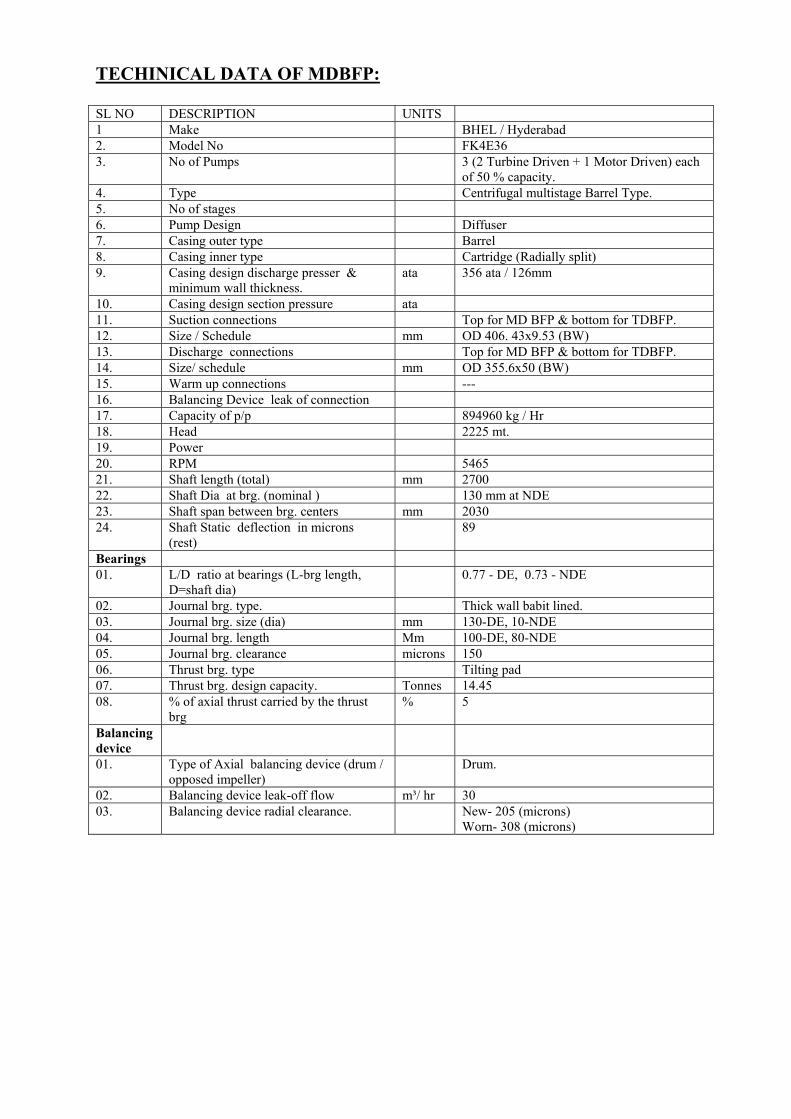
TECHINICAL DATA OF MDBFP: SL NO DESCRIPTION UNITS 1 Make BHEL / Hyderabad 2. Model No FK4E36 3. No of Pumps 3 (2 Turbine Driven + 1 Motor Driven) each
of 50 % capacity. 4. Type Centrifugal multistage Barrel Type. 5. No of stages 6. Pump Design Diffuser 7. Casing outer type Barrel 8. Casing inner type Cartridge (Radially split) 9. Casing design discharge presser &
minimum wall thickness. ata 356 ata / 126mm
10. Casing design section pressure ata 11. Suction connections Top for MD BFP & bottom for TDBFP. 12. Size / Schedule mm OD 406. 43x9.53 (BW) 13. Discharge connections Top for MD BFP & bottom for TDBFP. 14. Size/ schedule mm OD 355.6x50 (BW) 15. Warm up connections --- 16. Balancing Device leak of connection 17. Capacity of p/p 894960 kg / Hr 18. Head 2225 mt. 19. Power 20. RPM 5465 21. Shaft length (total) mm 2700 22. Shaft Dia at brg. (nominal ) 130 mm at NDE 23. Shaft span between brg. centers mm 2030 24. Shaft Static deflection in microns
(rest) 89
Bearings 01. L/D ratio at bearings (L-brg length,
D=shaft dia) 0.77 - DE, 0.73 - NDE
02. Journal brg. type. Thick wall babit lined. 03. Journal brg. size (dia) mm 130-DE, 10-NDE 04. Journal brg. length Mm 100-DE, 80-NDE 05. Journal brg. clearance microns 150 06. Thrust brg. type Tilting pad 07. Thrust brg. design capacity. Tonnes 14.45 08. % of axial thrust carried by the thrust
brg % 5
Balancing device
01. Type of Axial balancing device (drum / opposed impeller)
Drum.
02. Balancing device leak-off flow m³/ hr 30 03. Balancing device radial clearance. New- 205 (microns)
Worn- 308 (microns)

C. Diffuser / Impeller 1. No of Diffuser per First Stage 12 2. No of Blades of Normal Stage 12 3. 1st Stage Diffuser ID mm 366 4. Tongue ID, Normal Stages Mm 366 5. Impeller OD, 1st Stage mm 355 6. Impeller OD, Normal Stages Mm 355 7. Clearance between Impeller vane tip and
Diffuser / Volute tongue, 1st Stage Mm 4
8. Clearance between Impeller vane tip and Diffuser / Volute tongue, Normal Stage
Mm 4
9. Dia Clearance at Impeller wear ring, 1st Stage
Mm 0.58
10. Dia Clearance at Impeller wear ring, Normal Stage
Mm 0.58
FIRST STAGE DETAILS 1. Type Single Suction 2. Impeller Eye diameter, 1st Stage Mm 210 3. Impeller Eye area, 1st Stage (mm)² 23365 4. Impeller / Diffuser Width ratio,1st Stage 0.69 5. Impeller / Diffuser Width ratio, normal
Stage 0.69
6. No of Impeller Vanes ,1st Stage 7 7. No of Impeller Vanes ,normal Stage 7 8. Impeller Vane mounting arrangement
bet—impeller (in line/staggered) Staggered.
9. Location of center of gravity of the rotor (D atum line at)
mm 1448
CRITICAL SPEEDS 1. First critical speed of rotor
in water (rpm) New Worn
9124 8118
2. Second critical speed of rotor In water (rpm)
New Worn
12093 11926
3. First critical speed of rotor in air (rpm) 2331 4. Second critical speed of rotor in air
(rpm) 9338
Bearing Lubrication:- 1. Type Pressurised oil 2. Required flow per journal bearing m³/hr 4.2 3. Required flow per thurst bearing m³/hr 13.44 4. Bearing temperature ( Reco / Max ) Deg.C 100 / 80 5. Oil pressure required( Min / Reco / Max) Ata 2.5 / 3.0 / 3.5

VOITH COUPLING TECHNICAL DATA SHEET Geared Variable speed coupling R 18 KGS –14 API Rotation seen in direction of Input shaft Hydr. Circuit Output shaft the power flow CCW CW CCW Geared variable speed pump as boiler feed pump drive Power requirement of driven machine : Pa 7340 KW Motor speed : ne 1494 rpm Gear ratio : U1=Ze/Z1 109/32 Primary speed: n1 5092 rpm Full load slip S =2.3% Gear ratio: U2=Z2/Za =62/53 Max. output speed : na 5820rpm Regulation range : =4:1downwards Weight (without oil filling) Approx.9300kg Hydraulic oil types : HLP 32 to DIN 51524,
part 2 Oil tank filling : Approx. 2500 l Lube oil flow rate for booster pump : Lube oil flow rate for main motor : Lube oil flow rate for driven machine : Lube oil quantity for connecting couplings:
Σ 300 l/min. at 2 to 2.5 kg/cm2
Pump insert : Working oil pump (centrifugal pump ) and lube oil pump ( gear pump )jointly driven as gear –tooth system drive via the pump shaft .
Auxiliary lube oil pump : MZP 820 Motor for aux. Lube oil pump : DE 200 LA2 Technical data : 30 KW, 415V, 2950 rpm
IP 55, B5 Actuator: RH5- 30 C; S2 4k Continuous electronic power unit : KE 3 Transformer : 240V/220V/!70 VA
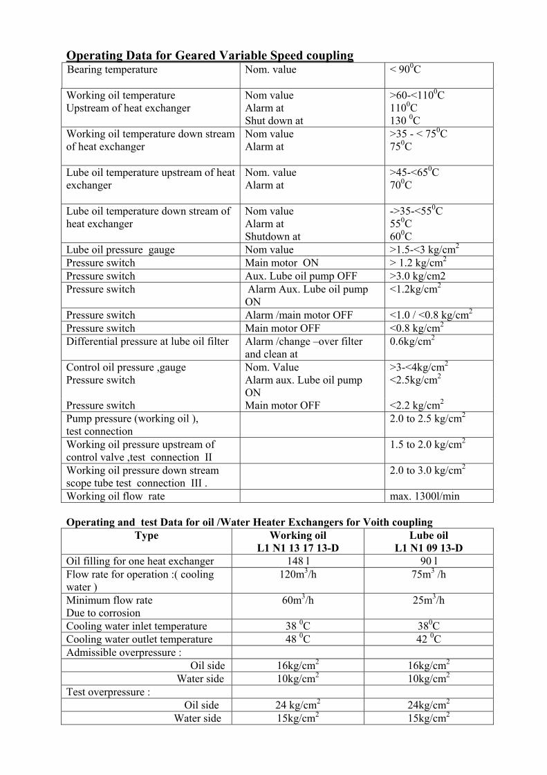
Operating Data for Geared Variable Speed coupling Bearing temperature
Nom. value < 900C
Working oil temperature Nom value >60-<1100C Upstream of heat exchanger
Alarm at Shut down at
1100C 130 0C
Working oil temperature down stream of heat exchanger
Nom value Alarm at
>35 - < 750C 750C
Lube oil temperature upstream of heat exchanger
Nom. value Alarm at
>45-<650C 700C
Lube oil temperature down stream of heat exchanger
Nom value Alarm at Shutdown at
->35-<550C 550C 600C
Lube oil pressure gauge Nom value >1.5-<3 kg/cm2 Pressure switch Main motor ON > 1.2 kg/cm2 Pressure switch Aux. Lube oil pump OFF >3.0 kg/cm2 Pressure switch Alarm Aux. Lube oil pump
ON <1.2kg/cm2
Pressure switch Alarm /main motor OFF <1.0 / <0.8 kg/cm2 Pressure switch Main motor OFF <0.8 kg/cm2 Differential pressure at lube oil filter Alarm /change –over filter
and clean at 0.6kg/cm2
Control oil pressure ,gauge Nom. Value >3-<4kg/cm2 Pressure switch Alarm aux. Lube oil pump
ON <2.5kg/cm2
Pressure switch Main motor OFF <2.2 kg/cm2 Pump pressure (working oil ), test connection
2.0 to 2.5 kg/cm2
Working oil pressure upstream of control valve ,test connection II
1.5 to 2.0 kg/cm2
Working oil pressure down stream scope tube test connection III .
2.0 to 3.0 kg/cm2
Working oil flow rate max. 1300l/min Operating and test Data for oil /Water Heater Exchangers for Voith coupling
Type Working oil L1 N1 13 17 13-D
Lube oil L1 N1 09 13-D
Oil filling for one heat exchanger 148 l 90 l Flow rate for operation :( cooling water )
120m3/h 75m3 /h
Minimum flow rate Due to corrosion
60m3/h 25m3/h
Cooling water inlet temperature 38 0C 380C Cooling water outlet temperature 48 0C 42 0C Admissible overpressure : Oil side 16kg/cm2 16kg/cm2 Water side 10kg/cm2 10kg/cm2 Test overpressure :
Oil side 24 kg/cm2 24kg/cm2 Water side 15kg/cm2 15kg/cm2

DATA SHEET FOR TURBINE OF BFP(TDBFP) OUTPUT UNIT Maximum output 7505 KW Design rating (economical rating ) 5735 KW Speed Speed turbine 5260 rpm Speed reduction gear output shaft - - Speed range 1495-5740 - PRSSURE Specified initial steam pressure (5) 6.33 ata Permissible deviation without limitation (1) 11.3 ata Permissible deviation (2) 12.0 ata Permissible deviation instaneously for a total duration of 12 hours per annum (2) 14.0 ata PRESSURE INSIDE THE TURBINE The pressure in the H.P wheel chamber of the turbine must not exceed the following value at maximum load and with salt deposits on the blading :
11.0 ata
The pressure in the I.P wheel chamber of the turbine must not exceed the following value:
- -
Extraction [pressure - - The extraction pressure may rise to and drop to pressure at exhaust flange 0.1064 ata TEMPRETURES Specified initial steam temperature 289.6 Permissible deviation without limitation 320.0 0C Permissible deviation for longer periods 328.3 0C Permissible deviation for 400 hours per annum 334.0 0C Permissible deviation for 80 hours per annum 348.0 0C
Data sheet for Oil Vapour Exhaust fan
Fan size UHPR-100 SWSI Capacity 0.11 M3/sec. Fan speed 2830 rpm Density of fluid 1.2 Kg./m3 Suction pressure 100 mm of wc BHP 0.263 Motor Manufacture BPL/ KEC / CGL OR EQV Type Sq. cage induction Facuatt output kw 0.37 Voltage 415V Full load amp. 0.79A Speed 2980rpm Insulation class B Mounting B5 Ambient temp./temp rise of 50 0c /70 0c Rotation view from NDE Clock wise Bearing type no. Seep Groove cell bearing No. -6305

Technical Data of CEP: Sl NO Description Unit 1. Manufacture BHEL/ Hyderabad 1.1 Model Number and No. of Pumps EN6J40 / 500, 3Nos 2 Design flow rate Kg/hr 790480 2. Design inlet conditions 2.1 Inlet Temperature Deg.C 49.2 2.2 Specific gravity 0.9881 2.3 NPSH required at center line of first
stage impeller
a) 3% head breakdown m 3.1 b)1% head breakdown m 4.2 c)0% head breakdown m 4.4 d) 40,000 hrs erosion life of first
stage impeller m 5.05
3. Design discharge conditions 3.1 Discharge pressure ata 28 3.2 TDH m 275 3.3 Shut off head m 347+(11)*=358 3.4 Pump Speed rpm 1486 4 Power Consumption at design
condition
4.1 Power input to motor at 50Hz kw 763 4.2 Loss in motor at 50Hz kw 32 4.3 power input to pump at 50hz kw 731 4.4 Overall efficiency % 77.6 5 Canister losses mwc 0.4 6. Minimum flow for continuous stable
operation m³/hr 300
7. Peripheral speed at the eye of first stage impeller
m/sec 18.97
8. Maximum residual thrust kg 2732 9. Number of stages 6 (Six) 10. Type of first stage impeller Double suction, radial 11. Impeller diameter mm 388 (OD) 12. Suction specific speeds for 1st stage 10950 13. Design pressure of bowl and
discharge components. ata 39
14. Outer casing (canister): 14.1 Minimum wall thickness mm 12 14.2 Design pressure ata 2 14.3 Depth below pump mounting flange mm 5892 15. Suction connection 15.1 Size /schedule 20” ANBI BI6.5, CL-300 15.2. Type of connection with piping Flanged, WNRF 15.3. Height of centerline above pump
mounting flange mm 1320

Sl NO Description Unit 16. Discharge connection 16.1 Size /schedule 12” ANBI BI6.5, CL-300 16.2 Type of connection with piping Flanged, WNRF 16.3 Height of centerline above pump
mounting flange mm 2020
17. Critical speeds. 17.1 First critical speed in water rpm 3380 17.2 Second critical speed in water rpm 5798 17.3 GD2 of rotor including coupling Kg-m2 32 17.4 Length mm 3606 17.5 Diameter mm 100(max) 17.6 Span between bearings mm 1350 17.7 Length mm 3167 17.8 Diameter mm 87 17.9 Span between bearings mm 1350 18 Bottom shaft 18.1 Length mm 2607 18.2 Diameter mm 88 (max) 18.3 Span between bearings (max) mm 1350 18.4 Method of coupling with adjacent
shafting Muff coupling
19 Radial bearings 19.1 Type & number Cutless rubber, 8 Nos 19.2 Size mm 100 20. Thrust bearing 20.1 Located in pump /motor In pump 20.2 Type & number Tilting pad, 1 no. 20.3 Design load kg 2732 20.4 Maximum load kg 6038 21. Bearing lubrication type: 22.1 Redial bearing Condensate 22.2 Thrust bearing Sump oil 23. Recommended hole size of suction
strainer 400 microns
24. Shaft sealing 27. Method of sealing Mechanical seal

TECHNICAL DATA FOR VACUUM PUMP
SL.NO. DESCRIPTION 1. Type of machine 2 BE1353 2. Additional type characteristics F65 3. Dimension drawing no. S98 4401 4. Direction of rotation (facing D.E.
shaft end ) Clockwise
5. Total weight 2. 0 T 6. Weight of rotor 760 KG 7. Starting moment of inertia
(with correctly filled machine) 37 KGM2
8. Foundation loading ACC. To drawing no.
T80 6051
9. Compressive force 24KN 10. Tensile force 3 KN 11. Tapped centre hole M24 X 50 12. Relief grove E2.5 X 0.4 DIN 509 13. Rolling –contact bearing a) Drive end bearing NU226E DIN 5412 b) Non –drive end bearing NU226E DIN 5412 c) Grease / LI soap base
(mineral oil )
DIN 51825-KP2K
d) Grease quantity 40 G e) Relubricating interval 400 operation hours 14. Greasing nipple 15. Intake flange of end shield DN 200 PN 10 DIN 2501 16. Discharge flange of end shield DN 200 PN 10 DIN 2501 17. Connecting flange for working
liquid on both end shields (on suction side)
DN 32 PN 10 DIN 2501
18. Connecting flange (for drawing and flushing) on both end shields
DN 32 PN 10 DIN 2501
19. Connection for leakage drain
RP 1 / 2 ISO 7 / 1
20. Screw plug for drain
G 1 /2 ISO 228

VACUUM PUMP MOTOR 3- phase induction motor type KA4355S-EB01Z Frame size 355S Rated output KW 135 Speed RPM 600 Rated voltage V 415 Rated current Amp 240 Direction of rotation ccw Relubrication period /quantity 5200h/40g Bearing D-end 6222 C3 Bearing N-end 6319 C3 Number of poles 10 Type of construction IMB3 Degree of protection IP55 Duty type S1 Connection D Frequency HZ 50 Temperature class F Ambient temperature 0 C 50 Type of grease DIN 51825 K3K Weight Ca. 1,65 t

DATE SHEET FOR RAW WATER PUMPS SL.NO. DESCRIPTION SPECIFICATION 1.01.00 GENERAL 1.01.01 Service Raw Water Pumps. 1.01.02 Manufacturer. Kirloskar Brothers Ltd. 1.01.03 Model Number BHR 70 1.01.04 Type of pumps. Vertical Turbine. 1.01.05 Numbers Off. 5 Numbers. 1.01.06 Whether Suitable for Parallel Operation. YES. 1.02.00 TECHNICAL PARTICULARS: 1.02.01 Guaranteed Rated Capacity. M3/hr. 2300 1.02.02 Guaranteed Pumps Head at Rated Capacity in MWC. 60 1.02.03 Total Blow Head at Rated Capacity in MWC 60.2 1.02.04 Shut-Off Head, WMC 74 1.02.05 Blow Efficiency at Rated Capacity. 91% 1.02.06 Pump efficiency rated capacity. 89.9% 1.02.07 Input power to pump at rated capacity in KW per
pump. 418
1.02.08 Guaranteed power consumption at rated capacity (at motor terminal) as per contract (during PG test) in KW.
413.59
1.02.09 Pump Input Power at Shut-Off, (KW) 330 1.02.10 Maximum Power Input to the Pump at Rated Speed
over the Range of Operation (KW) 440
1.02.11 Maximum Power Input to the Pump at 130% of Rated Speed over the entire Operation Range.
1.02.12 Maximum Power Input to the Pump in the event of Tripping of Operating Pumps where the Parallel Operation of Pumps are envisage.
1.02.13 Rated Output of Motor, KW 550 1.02.14 Pump Rated Speed, rpm (NOM) 990 1.02.15 Pump Runway Speed, rpm. 120% of Rated Speed. 1.02.16 Specific Gravity, Temperature and Viscosity of Liquid
Pumped. 134 rpm
1.02.17 Specific Gravity, Temperature and Viscosity of Liquid Pumped.
1.0, Ambient.
1.02.18 Pump – motor Set capable of starting with a) discharge Valve closed, (Yes/No) b) Discharge Valve opened, (Yes/No) c) Discharge Valve partially open, (Yes/No)
YES YES YES
1.02.19 Range of Pump Operation. 40% to 120% Rated Flow. 1.02.20 Maximum Flow, m3 /hr. 2900 1.02.21 Maximum Flow, m3 /hr. 600 1.02.22 Loses in Suction Bell & Column Pipe (MWC) 0.20 1.03.00 DESIGN & CONSTRUCTION FEATURES: 1.03.01 Number of Stages ONE 1.03.02 Type of Discharge Above Floor. 1.03.03 Whether Pull Out Design. NO. 1.03.04 Minimum Submergence required above edge of suction
Bell. a) At Rated Flow. b) At Maximum Flow
1400 mm 1500 mm
1.03.05 Impeller Diameter, mm

a) Min. Dia. b) Max. Dia. c) Actual Dia. For specified duty.
620 mm 775 mm 720 mm (Appx)
1.03.06 Size of Components a) Suction Bell b) Discharge Pipe with Flange Standard c) Column Size d) Column Suspension Length (total) (from
Operating Floor level to tip of Suction Bell)e) Maximum Column Length /Piece f) Suction Bell Velocity
i. At Rated Flow ii. At Maximum Flow.
950 mm 600 mm 600 mm 12500 mm 2500 mm 1.0 m/s 1.5 m/s
1.03.07 Method of Rotor Position Adjustment By Impller Adjustment Nut.
1.03.08 Pump Shaft Bearings a) Type b) Type of Lubrication c) Design life terms of hours of Continuous
Operation d) Arrangement of Cooling
I. Above min. water
level THORDON II. Below min. water
level-RUBBER Self. 25000 hrs Self
1.03.09 Thrust Bearing a) Type b) Location c) Type of Location d) Design Life in terms of hours of Continuous
Operation. e) Arrangement of Cooling.
Anti friction In Pump Grease / Oil 40000 hrs self Water
1.03.10 Shaft Sealing Arrangement a) Type b) If External Sealing Fluid is Required then:
i. Fluid Quantity ii. Pressure in Kg/cm2 (g)
Gland Packing. N.A N.A
1.04.00 MATERIAL OF CONSTRUCTION: 1.04.01 Suction Bell 2.5% Ni CI Gr FG 260 as
per Is-210 1.04.02 Column Pipe. MS (IS – 2062) 1.04.03 Discharge Elbow MS (IS – 2062) 1.04.04 Discharge Casing MS (IS – 2062) 1.04.05 Fasteners I n Column Assembly MS (Cadmium Coated) 1.04.06 Impeller CF8M

1.04.07 Impeller Blow 2.5% Ni CI Gr 260 As per
IS – 210 (250 BHN) 1.04.08 Wearing Ring (casing) Bronze Is 313 Gr V 1.04.09 Base Plate MS (IS – 2062) 1.04.10 Impeller Shaft SS – 410 ANLD 1.04.11 Line Shaft SS – 410 ANLD 1.04.12 Top shaft SS- 410 ANLD 1.04.13 Shaft Sleeve SS – 316 1.04.14 Shaft Coupling SS – 316 1.04.15 Shaft Bearings Rubber/Thordon. 1.04.16 Impeller Bearings Rubber in bronze shell. 1.04.17 Gland 2.5% Ni CI Gr 260 As per
Is – 210 (250 BHN) 1.04.18 Gland Packing Teflon 1.04.19 Mechanical Seal Not Applicable 1.04.20 Stuffing Box 2.5% Ni CI Gr 260 As per
IS – 210 (250 BHN) 1.04.21 Blow casing 2.5% Ni VI Gr 260 As per
Is – 210 (250 BHN) 1.05.00 NET WEIGHT: 1.05.01 Weight of Pump Assembly in Kgs. 7000 Kgs. (Appx) 1.05.02 Weight of Prime Mover in Kgs 4000 Kgs. (Appx) 1.05.03 Total weight of the whole Assembly offered in Kgs. 11000 Kgs. (Appx) 1.05.04 Total Weight of the Pump – Motor Assembly with
Pump Full of Liquid to be handled in Kgs.
1.06.00 REFERENCE DRAWINGS: 1. G.A. Drawing – TL 153 00060 – 1
2. C.S. Drawing – TL 153 00051 – 1
3. Characteristic Curves – HK –99-00-01

CW PUMP SPECIFICATION & OTHER DETAILS.
• Pump Type & Quality BHM 130, Single Stage, Wet Pit . Vertical Pump / 10 Nos.
• Client N.T.P.C. TALCHER • O.A. No 16G1F7910 / 01-01-2000 • Motor Detail BHEL
2100 KW / 18P / 11KV • Pump Capacity 30000 m3 / hr • Pump Head 19.7m • Pump Efficiency 87.00 % • Speed 332 rpm.

TECHNICAL DATA OF CW PUMP
SR. NO. Description Remarks 16.1 Pump Model / No of stage. BHM 130 / 1 Stage. 16.2 A. Delivery Size. 1700 mm dia.
B. Flange Drilling Standard AWWA C 207 – 94 Class D (86 PSI)
16.3 Direction of Rotation Clockwise viewed from top. 16.4 Loading Details
A. Dry Weight of the pump 37600 Kgs. B. Weight of the Motor. 32500 Kgs. C. Total Dynamic and Hydraulic load on
foundation. 139050 KGS
D. Refer G. A. Drawing for Forces and Moments. 16.5 Performance.
A. Standard of testing. HIS B. Working Head Range (Min / Nor / Max) 12/ 19.7 /24 mtr. C. Working Capacity Range (Min / Nor / Max) 18000 /30000 /36000 M3/ hr. D. Full Load Speed 332 rpm E. Max. Pump Input Power. 1830 Kw.
16.7 Max. Permissible Clearance after running at Site. A. Shaft sleeve and line shaft Bearing. 1.16 mm (Diametrical) B. Impeller and impeller guide Piece. 1.75 mm (radial) C. Shaft Sleeve and Thordon Bearing In Bell
Mouth. 0.9 mm (Diametrical)
16.8 Minimum Submergence Required at Duty point for Vortex free operation. Note: Please refer Sump Model Study report for recommended sump dimensions and geometry.
16.9 Hydrostatic Test Pressure. 4.50 kg/cm2 16.10 Maximum working pressure. 3.20 kg/cm2 16.11 Thrust Bearing.
A. Make / Model Mitchel B. Type Tilting Pad. C. Location In motor. D. Lubrication / cooling Oil Bath / water cooled

CW PUMP MOTOR
SL.NO. DESCRIPTION UNIT DETAILS 1.25 Direction of rotation as seen from top. - Clockwise 1.26 Weight of motor kg 32500 1.27 Bearings
a) Type of bearings. b). Recommended lubricant c). Guaranteed Running life.
- -
hours
Refer Doc. 32551/BRG Pad type thrust & Guide bearings at top and guide bearings at bottom. Infinite if maintained. Infinite if maintained properly.
1.28 GD2 value of motor. Kgm2 7400 1.29 GD2 value of load. Kgm2 2450 1.30 Terminal box.
a) No. of terminals brought out. b) Size and type of cable gland c) Size and type of copper lug. d) Max. size of accomodable cable e) Fault level withstand capacity.
Nos.
- - -
6(3-Main TB & 3- NTB) double compression Brass gland size T 13 in KBL’s scope 1x3C x 150 mm2 XLPE 11 KV U/A cable. 40 KA (750 MVA) for 1 sce.
1.31 Space heater a) Quantity b) Location c) Rated voltage d) Rated wattage (Total/Each. Heater)
Nos
- volts watts
4(connection in series parallel) inside the frame 240 V,1,50 Hz Ac 1600 / 1600
1.32 Type of coupling between motor and driven eqpt.
- Direct, Rigid coupling (M/s KBL to give details)
1.33 Winding details a) No. of turns per coil b) Size of wire
Nos Mm
9 7.5 *2.7
1.34 No load starting time without driven eqpt. Coupled a) At rated voltage. b) Size of wire.
Secs Secs
1.5 4.0
1.35 Starting time with driven eqpt coupleda) At rated voltage b) At min. permissible starting
voltage.
Secs Secs
2.0 6.0

ADDITIONAL DATA TO BE FURNISHED FOR HT MOTORS
SL.NO. DESCRIPTION UNIT DETAILS 3.1 Type of insulation system. - VIP Micalastic 3.2 Type of stator lead termination - Elastimold type 655 LR 3.3 RTDs for winding
a) No. of RTDs provided b) Resistance at 00 C c) Type of RTDs d) Make
Nos Ohm
- -
12 100 simplex 4 wire Pt-100 NTPC approved vendor.
3.4 Bearings a) Type of lubrication b) Whether bearing insulation
provided c) Dial type thermometer Make Type Range No. of contacts and rating Location d) Oil level indicator.
- - - -
0C - - -
Oil ISO VG46 or eqvt. Yes no NDE side NTPC approved vendor Mercury –in –steel for local Indication only 0 to 150 Without contacts Bearing bracket yes
3.5 Surge withstand capability a) For main insulation -test voltage -wave shape type (1.2/50
micros) b) For inter –turn insulation -test voltage -wave shape type (0.3/3
micros)
KV -
KV -
49 yes 32 yes
3.6 Capacity of coils to withstand high freq. Over voltage a) Test voltage b) Test freq.
KV KHz
27 200
3.7 Paint shade. - 692 as per IS:5 Enamel. 3.8 a) Efficiency & p.f. vs. load curve no.
b) Thermal withstand curve no. c) Current vs. time curve no. d) Torque & current vs. slip curve no.e) Slip vs. load characteristics. f) Mounting Dimension drawing no. g) Technical particular of Dial
Indicator. h) Technical particulars of RTD.
- - - - - - - -
IMC 2763 IMC 2765 IMC 2766 IMC 2764 IMC 2791 3-402-00-30380 Doc.: 32551/DIAL Doc.: 32551/RTD

SL.NO. Description Quantity
4.1 4.2
4.3
4.4
4.5 4.6 4.7 4.8
Space Heaters (240 V, 1 ph AC), 4 nos 1600 W each, Total Rating. Stator winding RTDs. Pt-100, Simplex, 4 wire, Between coil sides. Bearings RTDs. Pt-100, Duplex, 4 wire Top Thrust Bearing Top Guide Bearing Bottom Guide Bearing Dial type temperature indicators Mercury –in-steel, Without Contacts for local indication only -Top Thrust Bearing -Top Guide Bearing -Bottom Guide Bearing Main Terminal box- Elastimold. Neutral Terminal box- Non-PSTB, Suitable for mounting CTs Auxiliary Terminal box for space heater, RTDs and BTDs Current transformers – 11KV, CT Ratio 200/1A, KPV 250 V, RCT 1, Class PS
a) In neutral TB b) Loose for mounting in control panel.
1600W 12 nos 1 nos 1 nos 2 nos 1 nos 1 nos 1 set 1nos Yes 3 nos Nil

AIR COMPRESSOR DATA SHEET
SL.NO. DATA SHEET DESCRIPTION A 1 2 3 4 5 6 7 8 9
AIR COMPRESSOR MANUFACTURE MODEL NUMBER TYPE OF COMPRESSOR TOTAL NOS. OFFERED TYPE OF OPERATION LOCATION QUALITY SURVEILLANCE BY MATERIAL TESTING & IDENTIFICATION PERFORMANCE TEST STD
ATLAS COPCO AIRPOWER, BELGIUM & ATLAS COPCO INDIA LTD, PUNE ZR 250 – 10 OIL FREE SCREW COMPRESSOR 09 NOS CONTINUOUS LOAD & UNLOAD INDOOR BHEL / NTPC AS PER APPROVED QAP ISO 1217
B 1 2 3 4 5
SPECIAL FEATURES TYPE OF COOLING TYPE OF CONNECTION BETWEEN COMPRESSOR & DRIVE ANTIVIBRATION ARRANGEMENT TYPE OF CONTROL TYPE OF PANEL
WATER COOLED FLEXIBLE COUPLING PROVIDED WITH RUBBER BUFFERS DUAL “ELEKTRONIKON” LCD DISPLAY PANEL

C 1 2 3 4 5 6 7 8 9
10 11
MATERIAL OF CONSTRUCTION COMPRESSOR CASING ROTORS TIMING GEARS BEARINGS AIR SEALS SAFETY VALVES HOUSING VALVE DISC NON RETURN VALVE BLOW OFF VALVE OIL COOLER GEAR BOX GEARS
CAST IRON- GG20 COMPRESSION CHAMBERS PTFE COATED & BAKED, VERTICALLY SPLIT BARREL TYPE COMPRESSION CHAMBER. CARBON STEEL C – 35 PTFE COATED & BAKED LOW ALLOY STEEL – 21 Ni Cr Mo 2 CASE HARDENED, HELICAL– IN CLASS 6ROLLER BEARINGS & BALL BEARINGS HIGH ALLOY STEEL X 20 Cr Mo A 17 ASME & TUV APPROVED BRASS BRASS STAINLESS STEEL SPRING LOADED VALVE LOCATED IN CAST GGG – 40 HOUSING HIGH ALLOY STEEL X 5 Cr Ni 189 MATERIAL SS AISI 316 – CORRUGATED BRAZED PLATE CAST IRON – GGG 40 LOW ALLOY STEEL 14 Ni CR 18 CASE HARDENED

D 1 2 3
DRIVE DATA TYPE OF DRIVE POWER VOLTAGE / PHASE/ FREQUENCY FOR OTHER DETAILS REFER MOTOR DATA SHEET GIVEN SEPERATELY.
ELECTRIC MOTOR 270 KW 3300V / 3PH / 50 Hz
E1 1 2 3 4 5
PERFORMANCE DATA TOLERANCE AS PER ISO 1217 COMPRESSOR CAPACITY AT 45 DEG. C & 75% RH DISCHARGE PRESSURE DESIGN AMBIENT TEMPERATURE MAX. EFFECTIVE WORKING PRESSURE GUARANTEED POWER CONSUMPTION CAPACITY AS PER “1” PRESSURE AS PER “2"
37.95 m3 / min 8.0 Kg/ cm2 g 50 DEG. C 10 BARg 239Kw
E2 1 2 3 4 5
OTHER DETAILS COOLING WATER CONSUMPTION CORRESPONDING TO TEMP. RISE OF 10 DEG.C PRESSURE DROP OVER COOLING WATER SYSTEM MALE ROTOR SPEED DISPLACEMENT M.I OF COMPRESSOR EXCEPT COUPLING
5.52 LPS 0.39 BAR LP- 9185 RPM HP- 13052 RPM 761 LPS 9.234 KG.m2
F 1 2 3
CONSTRUCTION FEATURES NUMBER OF STAGES TYPE OF DRIVE COUPLING
TWO ELECTRIC MOTOR HIGH ELASTIC COUPLING
G 1 2 3 4
AIR FILTER MANUFACTURER FREE AREA EFFICIENCY NOMINAL CAPACITY FOR FILTER LOAD OF 0.027m2 / LPS
MANN-HUMMEL (BRANDED FOR AC) 20.5 m2
SAE FINE 98% FOR PARTICLE SIZE OF 0 MICRON 750 LPS

H 1 2 3 4 5 6 7 8
OIL COOLER TYPE INLET OIL PRESSURE MATERIAL OF PLATE DESIGN OIL SIDE PRESSURE DESIGN TEMPERATURE HYDRO TEST PRESSURE OIL FLOW WATER FLOW
PLATE 3.0 BAR AISI 316 16 BAR 225 BAR 24 BAR 0.8 LPS 0.46 LPS
I 1 2 3 4
MAIN BEARING TYPE – ROLLING BALL MAKE NUMBER OF BEARINGS PROVIDED METHOD OF LUBRICATION
SKF – NU SKF – OJ SKF 8 PER ELEMENT FORCED FED
J 1 2 3
LUBRICATION TIMING GEARS GEAR ASSEMBLY OIL SPECIFICATIONS
FORCED FEED FORCED FEED ISO VG- IN CONFORMATION WITH ISO 3448 HIGH QUALITY MINERAL OIL WITH OXIDATION INHIBITORS & GOOD WATER SEPERATION PROPERTIES.
K 1 2
OIL PUMP TYPE OIL SUMP CAPACITY
GEROTO 60 LITERS
L 1 2 3
LUBE OIL FILTER MANUFACTURER TYPE EFFICIENCY
MANN- HUMMEL (BRANDED FOR AC) PAPER CARTRIDGE BETA 12 > 200 (ISO 4406)
M 1 2 3 4
SIZE & TYPE OF CONNECTION AIR INLET AIR OUTLET COOLING WATER INLET COOLING WATER OUTLET
THROUGH AIR FILTER (INTERCONNECTED) 100 NB 65 NB 65 NB
N 1 2
NET WEIGHT WEIGHT OF THE COMPRESSOR ASEMBLY TOTAL WEIGJT OF THE COMPRESSOR
3400 KG 9400 KG
O 1 2 3
REFERENCE DRAWINGS QAP GA DRAWING P & I DIAGRAM
15040 00 031 15040 00 003 15040 00 004

CW Blow down P/P & Motor Eq. Sl. No 1705 80 1002.
No. of p/ps 3Nos.
Equipment Model 14UPH 2(KBL make)
Head 30.0m of WC.
Size 400 X300
Speed 990 rpm.
Flow 416.67 l/s
Motor
Eq.sl.no. NDAZ 1032
Quantity 3Nos
Model Frame –ND 355L
Rating 180KW
Speed 990rpm
Voltage / Frequency 415 V / 50 Hz
Full low current 308A
Service water pump and motor No of pumps 4Nos
Eq. Sl. No. 1737801021
Model KBL -SCT 150/48
Head 60mm WC
Flow 111 l/s
Motor
Eq. Sl. No. NADW 92671
Model ND 3158 (Compton greaves )
Voltage / Frequency 415V / 50 Hz
Rating 110KW
Full load current 180A
Type of connection ∆ connection
Speed 1485rpm
Bearing DE/NDE 6319-C3 / 6319-C3

GENERATOR General Make BHEL Generator type THDF 115/59 Code IEC 34/1, VDE 0530 Cooling, starter winding Directly water cooled. Rotor winding Directly hydrogen cooled. Main Exciter type ELR 70/90 –30/6-20 Pilot exciter type ELP 50/42 –30/16 Year of manufacture. 1996 Rating Apparent power 588MVA Active power 500MW Power factor 0.85 (Lag) Terminal voltage 21KV Permissible variation voltage ±1.05KV Speed /frequency rpm / Hz 3000/50 Starter current 16.166kA H2 pressure 3.5 bar Rated field current for rated output 4040A Rated field voltage 340A Inner connection of starter winding YY Class & type of insulation ----------- No of terminals brought out ----------- Main Exciter Active power 3780KW Current 6300A Voltage 600V Speed 3000 rpm Pilot Exciter Apparent power 65 KVA Current 195A Voltage 220 ± 22V Frequency 400 Hz Speed 3000 rpm P.F. 0.6 Resistance in Ohms at 20 0C Turbogenerator Main Excitor Pilot Excitor U-X 0.001440 ohms U-0 0.002518 ohms Stator Winding V-Y 0.001440 ohms F1-F2 0.592 ohms V-0 0.002538 ohms W-Z 0.001440 ohms W-0 0.002529 ohms U-V 0.00046 ohms Rotor Winding F1-F2 0.06700 ohms U-W 0.00046 ohms V-W 0.00046 ohms Rectifier Wheel Action Required Number of fuses Per rectifier wheel
30 (800 V,800 A)
-
Fuses , resistance Approx. 150 µ ohms - Number of diodes Per rectifier wheel
60
-
Number of fuse blown per bridge arm and rectifier wheel
2 fuses 3 fuses
Switch off field forcing. Shutdown turbine-generator, replace fuses and diodes.

MECHANICAL DATA for Generator
Torques, Critical Speed etc. Maximum short-circuit torque of stator at line –to-line single-phase short-circuit Moment of inertia of generator rotor shaft nk1 Critical speed (calculated) ns 2 nk3
Torques and Speeds 14585 10000 14.4 30.1 39.8
Units Knm Kgm2 S1 (V-GEN) S’(V-EXC) S’(S-GEN)
Generator Volume and Filling Quantities Generator volume (gas volume) CO2 filling quantity** H2 filling (to 3.5 bar)***
Volume 80
160 480
Units M3
M3 (s.t.p.) M3 (s.t.p.)
Weights Stator with end shields and coolers Shipping weight of stator Stator end shield, upper part TE Stator end shield, upper part EE Stator end shield, lower part, TE Stator end shield, lower part, EE Rotor H2 cooler section, including water channels Gas dryer One seal oil cooler (air side) One seal oil cooler (H2 side) One primary water cooler Exciter rotor
Weight 360000 265000 22066 6655
24200 9950
68000 1770 950 320 250 90
7550
UnitsKgKgKgKgKgKgKgKgKgKgKgKgKg
Component Rotor shaft Rotor copper Rotor wedges Retaining rings Damper wedges
Material 26NiCrMoV145 CuAg0.1Pf25 Cu Co BeZr XSCrMnN1818K CuAgO.1F25
Component Electrical sheet-steel Stator copper Bearing babbit seal rings babbit
Material 1.5 kW/Kg at 1 Tasla .5mm TK E-Cu58F20 Babbit V 738 Babbit V 738

Seal Oil System
Design data Seal oil pumps MKW 11 AP 001 and MKW 21 AP 001 Kind of pump Type Capacity Discharge pressure Pump motor Rating Voltage/frequency Current Speed Type of enclosure No.
Three Screw pump T3S-52/54 LHSBSG2RNJIBALA 258 LPM 12Kg/Cm2 CGL, ND132M 7.5 KW 415V,50 Hz 14.5 A 1500 RPM(Syn.) TEFC, IP55 2 x 100%
Seal oil pump MKW 31 AP 001 Kind of pump Type Capacity Discharge pressure Pump motor Rating Voltage Current Armature Speed Type of enclosure No.
Three screw pump T3S – 52/54 LHSG2RNJIBALA 258 LPM 12 Kg/cm2 CGL, AFS 225L 8.5 KW 220 V d.c. 67 A 1450 RPM TEFC, IP55 1 x 100%
Seal oil pump MKW 13 AP 001 Kind of pump Type Capacity Discharge pressure Pump motor Rating Voltage/frequency Current Speed Type of enclosure No.
Three screw pump T3S – 52/46 LHSG2RNJIBALA 130 LPM 12 Kg/cm2 CGL, ND 132M 4 KW 415 V, 50Hz 9.3 A 940 RPM TEFC, IP55 1 x 100%
Seal oil filters MKW 51 BT 001, MKW 51 BT 002 MKW 53 BT 001, and MKW 53 BT 002 Kind of filter Type Volumetric flow rate Degree of filtration Pressure drop across filter No. for air side No. for H2 side
Strainer-type filter 2.32.9 Ma(BOLL & KIRCH) 4.16 dm3/s 100 microns 0.3 bar with clean filter 2 x 100% 2 x 100% * 1.2 bar with 100% fouling

Gas System
Design data Co2 flash evaporator MKG 51 AH 001 Rating Voltage Heat transfer liquid Volume of heat transfer liquid Hole in orifice Relief valve on high-pressure side Relief valve on low-pressure side No.
18 kw 415 V HYTHERM 500(HPCL) 25 dm3 2.8 mm 175 bar 8 bar 1 No., full- capacity
Dublex gas dryer MKG 69 Gas dryer fan Motor rating Voltage/frequency Speed Type of enclosure Gas dryer absorber wt. of absorbent material Gas dryer heater Heater rating No.
1.1 Kw 415 V/50 Hz 2760 RPM IP54 19 Kg each tower 3kw, 415 volts, 3 1 no., full-capacity
Compressed air filter MGK 25 BT 001 Volume of activated carbon Service hours Throughput No.
3dm3 approx. 1500 h to 2000 h 80 m3/hr at 8 bar 1 no., full-capacity

Primary Water System
Design data Primary water pumps MKF12AP001 and MKF22AP001 Kind of pump Type Speed Capacity Discharge head Pump motor Rating Voltage Frequency Speed Type of enclosure No. Main filters MKF 52 BT 001 and MKF 52 BT 002 Kind of filter Type Volumetric flow rate Degree of filtration Pressure drop across filter No. Fine filter MKF 60 BT 001 Kind of filter Type Volumetric flow rate Pressure drop across filter No. Ion exchanger MKF 60 BT 001 Volume Resin Resin volume No.
Centrifugal pump CPK-Cm 65-250 (S) KSB MAKE 2950 RPM 70 m3/Hr 80 m ND225 M (CGL) 37KW 415 V three-phase a.c. 50 Hz 2950 RPM TEFC 2 Nos., full-capacity Strrainger-type filter with magnet bars 1.53.1 (Boll & Kirch) 25 dm3/s max. 150 µm
0.1 Bar with clean filter 1.2 bar with 100% fouling
2 nos., full-capacity 1 plug. 1 cartridge 1.55.1 (Boll & Kirch) 0.42 dm3/s max. 0.15 bar with clean filter 1.2 bar with 100% fouling 1 No., fuill-capacity 83 litres Lewatit 56 litres (45 kg) 1 no., full-capacity
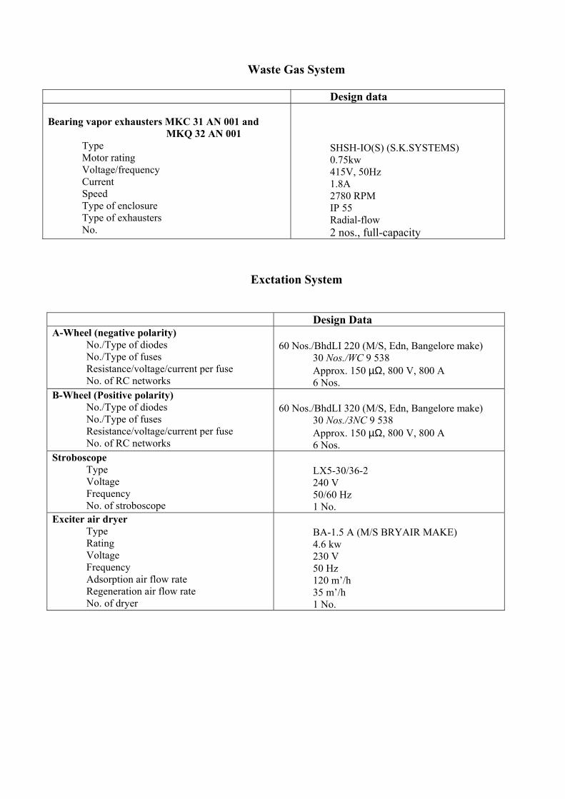
Waste Gas System
Design data Bearing vapor exhausters MKC 31 AN 001 and MKQ 32 AN 001 Type Motor rating Voltage/frequency Current Speed Type of enclosure Type of exhausters No.
SHSH-IO(S) (S.K.SYSTEMS) 0.75kw 415V, 50Hz 1.8A 2780 RPM IP 55 Radial-flow 2 nos., full-capacity
Exctation System
Design Data A-Wheel (negative polarity) No./Type of diodes No./Type of fuses Resistance/voltage/current per fuse No. of RC networks
60 Nos./BhdLI 220 (M/S, Edn, Bangelore make) 30 Nos./WC 9 538 Approx. 150 µΩ, 800 V, 800 A 6 Nos.
B-Wheel (Positive polarity) No./Type of diodes No./Type of fuses Resistance/voltage/current per fuse No. of RC networks
60 Nos./BhdLI 320 (M/S, Edn, Bangelore make) 30 Nos./3NC 9 538 Approx. 150 µΩ, 800 V, 800 A 6 Nos.
Stroboscope Type Voltage Frequency No. of stroboscope
LX5-30/36-2 240 V 50/60 Hz 1 No.
Exciter air dryer Type Rating Voltage Frequency Adsorption air flow rate Regeneration air flow rate No. of dryer
BA-1.5 A (M/S BRYAIR MAKE) 4.6 kw 230 V 50 Hz 120 m’/h 35 m’/h 1 No.
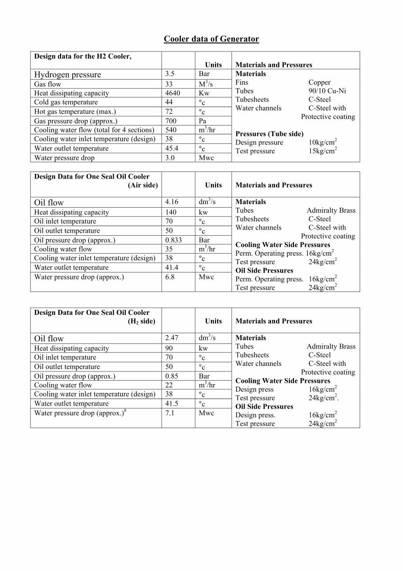
Cooler data of Generator
Design data for the H2 Cooler,
Units
Materials and Pressures
Hydrogen pressure 3.5 Bar Gas flow 33 M3/s Heat dissipating capacity 4640 Kw Cold gas temperature 44 °c Hot gas temperature (max.) 72 °c Gas pressure drop (approx.) 700 Pa Cooling water flow (total for 4 sections) 540 m3/hr Cooling water inlet temperature (design) 38 °c Water outlet temperature 45.4 °c Water pressure drop 3.0 Mwc
Materials Fins Copper Tubes 90/10 Cu-Ni Tubesheets C-Steel Water channels C-Steel with Protective coating Pressures (Tube side) Design pressure 10kg/cm2 Test pressure 15kg/cm2
Design Data for One Seal Oil Cooler (Air side)
Units
Materials and Pressures
Oil flow 4.16 dm3/s Heat dissipating capacity 140 kw Oil inlet temperature 70 °c Oil outlet temperature 50 °c Oil pressure drop (approx.) 0.833 Bar Cooling water flow 35 m3/hr Cooling water inlet temperature (design) 38 °c Water outlet temperature 41.4 °c Water pressure drop (approx.) 6.8 Mwc
Materials Tubes Admiralty Brass Tubesheets C-Steel Water channels C-Steel with Protective coating Cooling Water Side Pressures Perm. Operating press. 16kg/cm2
Test pressure 24kg/cm2 Oil Side Pressures Perm. Operating press. 16kg/cm2
Test pressure 24kg/cm2
Design Data for One Seal Oil Cooler (H2 side)
Units
Materials and Pressures
Oil flow 2.47 dm3/s Heat dissipating capacity 90 kw Oil inlet temperature 70 °c Oil outlet temperature 50 °c Oil pressure drop (approx.) 0.85 Bar Cooling water flow 22 m3/hr Cooling water inlet temperature (design) 38 °c Water outlet temperature 41.5 °c Water pressure drop (approx.)8 7.1 Mwc
Materials Tubes Admiralty Brass Tubesheets C-Steel Water channels C-Steel with Protective coating Cooling Water Side Pressures Design press 16kg/cm2
Test pressure 24kg/cm2. Oil Side Pressures Design press. 16kg/cm2
Test pressure 24kg/cm2

Design Data for the Primary water cooler, (2 Sections)
Units
Materials and Pressures
Primary water flow 18.06 dm3/s Heat dissipating capacity 2082 kw Primary water inlet temperature 75 °c Primary water outlet temperature 48 °c Primary water pressure drop 840 Mbar Cooling water flow 500 mVhr Maximum cooling water inlet temperature 38 °c Cooling water outlet temperature 41.6 °c Cooling water pressure drop* 3.5 mwc
Materials Shell SS Tubes SS Tubesheets SS Water channels C-Steel with protective coating Primary Water Side Pressures Design press. 10kg/cm3 Test pressure 15kg/cm2
Cooling Water Side Pressure Cooling press. 10kg/cm2 Test pressure 15kg/cm2
Primary Water Specification Conductivity < 10 µmho/cm (preferably 0.5 µmho/cm) PH 6-8 Dissolved O2 Minimum , preferably less than 100ppb Dissolved CO2 Minimum , permissible conductivity Chlorides after a strongly acidity cation exchanger Other anions < 0.2µmho/cm Ammonia Minimum ,test with Nessler’s solution as a
regent shall not cause a change in color Cu, dissolved/ undissolved Less than 20 ppb Fe, dissolved / Undissolved Less than 20ppb Dissolved solids The water shall not contain chemicals from
treatment process , such as hydrazine, morphine, levoxine, phosphate, etc.
Specification for ion Exchange resins Cation exchanger
( Lewatit S100KR/H/chloride-free) Anion exchanger (Lewatit M500 KR/OH/chloride-free)
Functional group Strongly acidic Very strongly basic Grain shape Beads Beads Particle size (0.3-125)mm 0.3-1.25)mm Bulk density of swollen resin (800-900)g/dm3 (670-750)g/dm3 Resin form H-ions OH-ions Specific load up to 40 dm3/h X dm3 40 dm3/h Xdm3 Total capacity of swollen resin
(1.9-2.2)mol/dm3 (1.1-1.6) mol/Dm3
Useful capacity min 50 gCaO/dm3 16 gCaO/dm3 Chloride content up to 50 mg/dm3 50 mg/dm3 Thermal stability up to 120 °C 70 °C Stability in PH range Unlimited Unlimited Shelf life min. (in original packing at temperatures of 1°C to + 400 °C
5years 3years

SPECIFICATION OF GENERATOR TRANSFORMER
OFAF HV/LV-200MVA 1 ph ,50 Hz, YNd11 No load Volt. HV-420/√3 No Load Volt. LV-21 Year of manufacture-2002 HV line current –824.8A Line & wdg. –153515kg. LV line current – 9523.8A Wt. Oil –44325 kg. Temp rise oil (0C )- 35 over ambient of 500C. Total wt –252065 kg Temp rise oil (0C )- 40 over ambient of 500C. Oil quantities – 50950 Litre Insulation Level HV- 51 1180L1 1425-AC 38 chopped L1-1570
LV-L1 125-AC 50 Off CKT tap switch position.
Connection
HV Terminals LV terminals
3TO 1N TO VOLT Current Volt Current 1 (max.tap) 8 462/√3 749.80A 2 7 415/√3 767.2 3 4 6 441/√3 785.5 4 4 5 430.5/√3 804.7 21KV 9523.8A 5 (Nor.Tap)
3 420/√3 824.8
6 7 409.5/√3 845.9 7 6 399/√3 868.2 8 8 5 388.5/√3 891.7 9 (Min tap)
8 4 378/√3 916.4

MAKE –BHEL TYPE OF Cooling ON AF /AN Rating HV 50/40 MVA Sl. No 6005948 Rating LV 50/40 MVA Electrical spec. No-601049 No Load voltage HV 400KV Man year –2001 No Load voltage LV 11.5KV Diagram DRG. No.
4601900058 Line current HV 72.17 Amp OGA DRGNo. 0460000033 Line current LV 2510.22Amp Core &wdg- 59720 kg Temp rinse oil 50 c over ambient temp 50 C W.T of oil – 37770kg Temp rinse wdg. 55 C over ambient temp50 C Total oil -139395 kg Transport Wt –75960 kg Untanking w.t 9800kg Purchase order LION CS 4330-201-2-FC-
NOA-4033 dtd: 30:08:00 Customer- NTPC TSTPP.
3,50HZ. Hv Posn9/LV Nor .Tap 12.5+ 10% Hv Posn 1/LV Max.Tap. 9.5% (Min.)
Hv Posn 17/LV Min.Tap. 16.5% (Max)
Insulation Level
H.V. – SI 1180L1 1425 –AC 38 chopped L1 – 1570
L.V. –L1 75 –AC 28
ICT- 1U1,!V1, 1W1
Posn Connection Voltage Current HV LV wdg. 3 TO 1NTO KV ON
AF50 MVA
ON AN 40MVA
KV 50MV 40 MVA
12 440 65.61 52.49 2 11 435 66.36 53.09 3 10 430 67.13 53.71 4 4 9 425 67.92 54.34 5 8 420 68.73 54.99 11.5 2510.22
MVA 2008.17 MVA
6 7 415 69.56 55.65 7 6 410 70.41 56.33 8 5 405 71.28 57.02 9abc 9b 9a 4, 3, 12 400 72.17 57.74 10 11 395 73.08 58.47 11 10 390 74.02 59.22 12 9 385 74.98 59.8 13 8 380 75.97 60.77 14 7 375 76.98 61.58 15 6 370 78.02 62.42 16 5 365 79.09 63.27 17 4 360 8.19 64.15

TECHNICAL SPECIFICATION OF UNIT TRANSFORMER Type of Cooling ON AF/ ON AN Insulation Level Rating HV (MVA) 45/36 HV-L! 1125-AC50 Rating LV (MVA) 45/36 HV L1-75-AC28 No.load voltage HV (KV) 21 No.load voltage LV (KV) 11.5 Line current HV (Amp) 1238.64 Line current LV (Amp) 2261.87 Temp Rise oil(0C) 50 over Ambient of 50 0C Temp Rise wdg.( 0C) 55 over Ambient of 500C Phase 3 Frequency 50 HZ Connection symbol Dy n1 Impedance voltage HV position71LV (Nor.Tap)
11.32%
HV pos. 1/LV (Max.Tap) 11.32% HV pass 17/LV (Min. Tap) 11.13% Core &wdg.(kg) 40065 WT of oil (kg) 22255 Total WT (Kg) 86205 Oil quantity 25530 NTPC ELECTRICAL TESTING
LABRORATORY TSPP
VOLTAGE & CURRENT HV TERMINAL 1U, 1V,1W
LV terminal 2U 2V 2W
Position OLC Connection Voltage Line Current (Amp) Voltage Line Current (Amp) 3 TO 2TO (K v) ON AF 45
MVA ONAF36 MVA
(Kv) ON AF 45 MVA
ONAF36 MVA
1 (Max) 12 22.58 1150.86 920.69 2 11 22.31 1164.40 931.52 3 10 22.05 1178.27 942.61 4 4 9 21.79 1192.46 953.97 5 8 21.53 1207.00 965.60 6 7 21.26 1221.91 977.52 7 6 21.00 1238.64 990.90 8 5 20.74 1252.84 1002.27 9a 4 9b 3 20.48 1268.90 1015.12 11.5 2261.87 1809.49 9c 12 10 11 20.21 1285.38 1028.30 11 10 19.95 1302.39 1041.84 12 12 9 19.69 1319.66 1055.73 13 8 8 19.43 1337.49 1069.99 14 7 19.16 1355. 1084.65 15 6 18.90 1374.64 1099.71 16 5 18.64 1394.06 1115.20 17 4 18.38 1413.92 1113.14

SYCHRONOUS MACHINE DATA AND SPECIFICATION 1.MACHINE DATA The DAVR has been designed and manufactured for the machine having following technical details. Type of machine Sl.No. Description Abbre. Unit Value 1 Rated output - MW/MVA 500 2 Stator voltage Un VAC 21000 3 Stator current In AAC 16200 4 Synchronous speed Ns Rpm 3000 5 Power factor cosφ - 0.85 6 System factor Hz C/s 50_ 7 Machine reactance: a) Synchronous reactance
i) direct axics unsaturated Xd p.u. 2.31 ii)Quadratture axis Xd p.u. 2.19 b) Direct axis transient reactance i) Saturated X’q p.u. 0.2413 ii) unsaturated X’du P.u. 0.2525 c) Direct axis sub-transient reactance i)saturated X”d p.u. 0.1719 ii) Unsaturated X”du p.u. 0.194 8 Machine time constants: . i) Direct axis ,transient open circuit T’do Sec 9.14 ii) Direct axis ,transient closed circuit T’d Sec. 1.00 iii) Sub –transient T”d Sec. 0.03 iv) Armature Ta Sec. -- 9 Field winding resistance at 20 0C Rf20 Ohm 0.067 10 Field exicitation requirement i) No. load field voltage Ufo VDC 121.3 ii) No. load field current Ifo ADC 1380 i) No. LOAD EXCITER DIELD CURRENT UFN VDC 30 IV)nominal field curent Ifn ADC 404 v) Nominal exciter field current Iefn ADC 86 vi) Max. cont. exciter field current Iefmax ADC 107 vii) Exciter field ceiling voltage Ud VDC 115 viii) Exciter field ceiling current Id ADC 158A ix) Duration of field forcing - Sec. 10_ 11 Field test voltage - Kvrms 2_ 12 Synchronizing slip -- % --- 13 AVR CT ratio -- AAC/AAC 20000/5 14 AVR PT ratio --- VAC/VAC 22000/110 15 Ambient -- 0C 50_ 16 Altitude -- meters 1000

53
2. SPECIFICATION OF STATIC EXCITATION EQUIPMENT SL.No. Description Unit Value 1 Accurarcy of excitation control % +0.5 2 Range of voltage control in auto % 90 Ugn-110 3 Range of voltage control in auto % 0- 110 Ifn 4 Range reactive current
compensation % Upto+15
5 Frequency range of operation Hz 47.5-52.5 6 Total No. of parallel
THY.bridgees No. 2
7 No.of redundant THY. Bridges No. 1 8 Protection class Ip31 9 Excitation equipment rating a) Voltage VDC 62.78 b)Current ADC 86 10 Range of PF regulation NA 11 Station battery supply VDC 220

54
DATASHEET FOR MAIN BOILER PLANT NAME TALCHER –
STAGE –II 4X500MW
PROPOSED FUEL Sub Bituminous coal Ash fusion Temp.
HHV Kcal /kg Grindability (HGI)
FC %22.00 Vol %21.0 M% 15.00
Ash % 42.00
S% 0.37
1400 0C 3300 55
FUEL BURNING EQUIPMENT TYPE MAKE
&NOS. CONTROL CAPACITY DISPOSITIO
N MAIN BOILER
Tilting tangential
BHEL ,40 Air damper 47.5X10⁶kca l/ hr Corners
Stabilisation burner
Tilting tangential
BHEL ,20 Air damper 23.3X10⁶kca l/ hr Corners
Mills XRP 1003 BHEL ,10 Motor kW:525 Speed (rpm):600
65.5 t/ hr System Cold PA
FURNACE Type: Balanced Draft Furnace with fusion Welded Water walls WIDTH : 19939mm DEPTH : 16559mm Volume : M3 19153
Fuel Heat input : 1230.3X 106 kcal/hr Boiler Controlled Circulation With Rifled
Tubing (cc+) , Radiant Reheat , Dry Bottom, Top Supported
Drum : 207 kg/cm2(g) DESIGN
DESIGNATION : 19939 313 –51 CC+ 16559 242-51 pr
essu
re
Super heater out let :178.0 kg/ cm2(g) –BMCR
SUPER HEATER Stage: 1 Type : LTSH Horizontal and pendant
8240
Stage : II Type : SH division panellette (projected)
1319
Total H.S. m2
Stage: III Type : SH Finish platen (projected) H
.S.A
rea
m2
1176
ATEEMPERATOR Type :Spray No. of Stages
Medium of Spray :Feed water
REHEATER Type: Radiant Front platen, Rear pendant.
Total : H.S m2 7122 Control: Burner Tilt and Excess
Air ECONMISER Type: plain Tube Total : H.S.m2 17650 No. of Blocks: 3
Total :HS m2 Pri. 33296 Sec.62720
Motor kw Primary 11 Secondary 18.5
AIR HEATER Type : BI- Sector Primary 26.5 VIM 2000 Secondary 30.0 VI 2000
Nos. Primary : 2 No. Secondary : 2 No.
Make : BHEL
Single stage
55
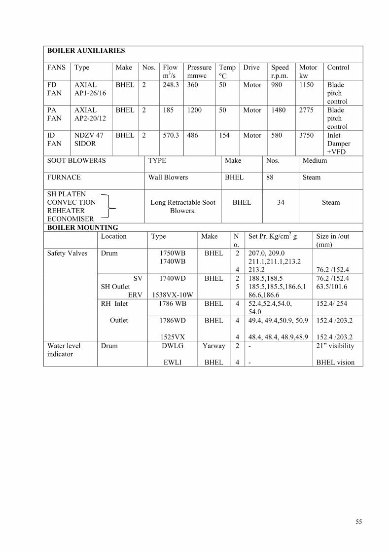
BOILER AUXILIARIES
FANS Type Make Nos. Flow m3/s
Pressure mmwc
Temp°C
Drive Speed r.p.m.
Motor kw
Control
FD FAN
AXIAL AP1-26/16
BHEL 2 248.3 360 50 Motor 980 1150 Blade pitch control
PA FAN
AXIAL AP2-20/12
BHEL 2 185 1200 50 Motor 1480 2775 Blade pitch control
ID FAN
NDZV 47 SIDOR
BHEL 2 570.3 486 154 Motor 580 3750 Inlet Damper +VFD
SOOT BLOWER4S TYPE Make Nos. Medium
FURNACE Wall Blowers BHEL 88 Steam
SH PLATEN CONVEC TION REHEATER ECONOMISER
Long Retractable Soot
Blowers.
BHEL
34
Steam
BOILER MOUNTING Location Type Make N
o. Set Pr. Kg/cm2 g Size in /out
(mm) Drum 1750WB
1740WB BHEL 2
4
207.0, 209.0 211.1,211.1,213.2 213.2
76.2 /152.4
SV SH Outlet ERV
1740WD
1538VX-10W
BHEL 2 5
188.5,188.5 185.5,185.5,186.6,186.6,186.6
76.2 /152.4 63.5/101.6
1786 WB BHEL 4 52.4,52.4,54.0, 54.0
152.4/ 254
Safety Valves
RH Inlet Outlet 1786WD
1525VX
BHEL 4
4
49.4, 49.4,50.9, 50.9 48.4, 48.4, 48.9,48.9
152.4 /203.2 152.4 /203.2
Water level indicator
Drum DWLG
EWLI
Yarway
BHEL
2
4
- -
21” visibility BHEL vision

56
MAIN PARAMETERS OF BOILER
FUEL DESIGN COAL
GENERATOR UNIT 100% BMCR
500MW 250 MW
Superheat MW 500 250 FLOW
Reheat T/h 1675 1498.5 772.8
Total Heat output of System (Q Duty ) Mkcal/h 1073.4 973.8 539.1 Pressure of super Heater Outlet Kg/cm2 (g) 178.0 176.4 170.8 Temperature at SH Outlet 0c 540 540 540 Pressure at Reheater inlet Kg/ cm2 (g) 44.88 42.86 21.15 Temperature at Reheater inlet 0c 337.5 336.5 311.4 Pressure at Reheater outlet Kg/ cm2 (g) 42.9 40.97 20.24
STEA
M
Temperature at Reheater outlet 0c 540 540 540 Feed water temperature (Eco inlet) 0c 255.2 253.4 219.2 Ambient Air temperature 0c 27 27 27 Combustion Air Temperature (secondary ) 0c 318 312 271 Fuel quantity t/h 373 338 187 Air quantity (total combustion Air) t/h 2014 1831 1012
Temp. of Gas at Boiler Exit (Corrected) 0c 127 125 121 Temp. of Recalculation Gas 0c - - -
FLO
W
GA
SS
Quantity of Recalculation Gas
t/h
-
-
-
Efficiency Base on HHV (BS 2885) % 82.27 87.32 87.27

57
PREDICATION PERFORMANCE DATA (Design Coal- Constant Pressure)
CONTENTS SECTION DESCRIPTION SHEET NO.
I FLOW II TEMPERATURE III PRESSURE (STEAM &WATER) IV GAS VELOCITIES V PRESSURE & DRAFTS (AIR &GAS) VI FUEL VII MILL & BURNER PERFORMANCE VIII O2 , C O2 & EXCESS AIR IX AMBIENT CONDITION S X HEAT BALANCE
The attached perfomance data are predicated only and are to be constructed as being guaranteed except where the value coincide with guarantees stated under the performance guarantee section

58
1.FLOW
Description Unit HP Heaters in HP heaters out
BMCR 500MW 400MW 300MW 250 MW Max O/P Steam Super heater outlet Reheater outlet
t/h
t/h
1675.0
1397.4
1498.5
1335.1
1198.9
1078.1
909.3
825.8
772.8
669.2
1451.6
1445.5
t/h
1675.0
1496.5
1156.9
846.3
712.8
1352.6 t/h
0 2 42 63 60 99
Water Feed water SH spray Rhspray
t/h 0 0 0 0 0 17
t/h
617
536
444
350
331
608
t/h
45
42
35
30
31
5
AIR AH Outlet (Primary) Tempering air AH outlet (Secondary ) Total Combustion Air
t/h
t/h
1146
2014
1047
1831
817
1502
586
1172
444
1012
1160
2030
t/h
2228
2025
1662
1296
1118
2244
t/h
2388 2183 1812 1438 1254 2403
t/h
778 694 593 490 482 775
t/h
1450 1331 1069 807 636 1469
t/h 854 771 669 564 553 852
Gas Flue gas at RAPH in let (Secondary & Primary ) Flue gas at RAPH out let (Secondary & Primary ) Inlet PAH Inlet SAH Out let PAH Inlet SAH
t/h
1534
1412
1143
874
701
1551
Fuel Coal
t/h
373
338
278
217
187
375

59
II.TEMERATURE Description
Unit HP Heaters in HP heaters out
BMCR 500MW 400MW 300MW 250 MW Max O/OP Steam
0C 361 360 357 354 354 359 0C 365 364 364 363 362 366 0C 403 403 406 406 403 425 0C 403 402 390 378 373 394 0C 477 474 467 458 455 468 0C 477 474 467 458 455 468
Sat temp in Drum LTSH inlet LTSH outlet SH panel inlet SH panel outlet SH platen outlet SH platen outlet RH inlet RH outlet
0C 0C 0C
540 338 540
540 337 540
540 329 540
540 321 540
540 312 540
540 351 540
Water 0C 255 253 243 230 219 172 Economiser inlet
Economiser outlet 0C 322 320 312 301 292 287
0C 27 27 27 27 27 27 0C 318 313 299 282 269 274
Air Ambient AH Outlet (primary) AH Outlet (secondary)
0C 318
312 298 283 271 273
gas 0C 1402 1398 1394 1390 1366 1398 0C 1136 1123 1094 1060 1028 1135 0C 1039 1030 995 950 915 1041 0C 897 876 835 786 752 897 0C 704 682 645 602 576 706 0C 558 543 516 486 468 562 0C 346 337 317 295 279 297
SH panel inlet SH Platen inlet RH Front inlet RH Rear inlet LTSH inlet Economiser inlet Air heater inlet Air heater outlet 0C 127 125 122 121 121 113

60
III. PRESSURES (STEAM &WATER) Description
Unit HP Heaters in HP heaters out
BMCR 500MW 400MW 300MW 250 MW Max O/P Pressure
Kg/cm2(g) 178.0 176.4 173.7 171.6 170.8 175.9 Kg/cm2(g) 189.0 185.2 179.3 174.8 173.1 184.2 Kg/cm2(g) 193.5 188.8 181.6 176.2 174.1 187.6 Kg/cm2(g) 199.1 193.5 185.7 179.5 177.2 192.4 Kg/cm2(g) 42.9 41.0 32.9 25.1 20.2 45.2
Superheater outlet LTSH outlet Drum Economiser inlet Reheater outlet Reheater inlet Kg/cm2(g) 44.9 42.9 34.5 26.2 21.2 47.3
Kg/cm2(g) 15.5 12.4 7.9 4.6 3.3 11.7 Kg/cm2(g) 1.98 1.89 1.51 1.15 0.91 2.31
Pressure drop Superheater system Reheater system Economiser including Static head
Kg/cm2(g) 5.6 5.0 4.0 3.4 3.0 4.0
IV. GAS VELOCITIES IN SH/RH/ECO BANKS
HP Heaters in HP heaters out
Description
Unit
BMCR 500MW 400MW 300MW 250 MW Max O/P Platen SH m/s 7.7 6.9 5.5 4.2 3.5 7.7 RH Front m/s 8.9 8.0 6.3 4.8 4.0 9.0 RH Rear m/s 9.3 8.3 6.5 4.9 4.1 9.4 LTSH m/s 9.5 8.5 6.7 5.0 4.2 9.6 Econmiser m/s 8.8 7.8 6.2 4.7 3.9 8.9

61
V. PRESSURE AND DRAFTS (AIR AND GAS)
HP Heaters in HP heaters out
Description
Unit
BMRC 500MW 400MW 300MW 250 MW Max O/P Primary
PA Fan inlet mmwc -11 -9 -7 -5 -4 -11 PA Fan outlet mmwc 874 873 846 815 777 862 Air heater inlet mmwc 861 862 838 809 772 849
Air heater outlet mmwc 804 818 806 788 754 793 Mill inlet mmwc 679 695 686 672 642 668
Mill outlet mmwc 301 311 304 293 280 290 Secondary air
FD fan inlet mmwc -13 -10 -7 -4 -2 -13 FD fan outlet mmwc 180 161 127 101 89 177
Air heater inlet mmwc 164 148 118 96 86 161 Air heater outlet mmwc 116 107 93 82 77 115
Windbox pressure mmwc 70 70 70 70 70 70 Gas
Furnace mmwc -5 -5 -5 -5 -5 -5 SH platen inlet mmwc -5 -5 -5 -5 -5 -5
RH Inlet (Platen outlet)
mmwc -6 -6 -6 -6 -6 -6
LTSH inlet (RH outlet)
mmwc -14 -12 -10 -9 -8 -14
Economiser inlet (LTSH outlet)
mmwc -34 -30 -25 -23 -21 -34
Economiser outlet mmwc -53 -45 -35 -30 -26 -53 Airheater inlet mmwc -76 -65 -52 -45 -39 -76
Airheater outlet mmwc -191 -158 -122 -95 -87 -182 EP inlet mmwc -217 -181 -141 -110 -101 -208
ID fan inlet mmwc -263 -220 -171 -132 -120 -254 ID fan outlet mmwc +26 +23 +19 +16 +15 +26

62
VI. FUEL The fuel data for design coal are as follows: Description Unit Fuel Design coal Proximate Analysis: Fixed carbon % 22 Volatile matter % 21 Moisture % 15 Ash % 42 Grindability Index HGI 55 Higher Heating Value (HHV) Kcal/kg 3300 Size of coal to Mill mm 25 (Approx) Ultimate Analysis : Carbon % 33.73 Hydrogen % 2.35 Sulphur % 0.37 Nitrogen % 0.75 Oxygen % 5.48 Cabonates % 0.27 Phosphorus % 0.05 Moisture % 15.0 Ash % 42.0
VII. MILL AND BURNER PERFORMANCE
HP Heaters in HP heaters out
Description
Unit
BMCR 500MW 400MW 300MW 250 MW Max O/P No. of mills in operation
Top 7 Top 6 Top 5 Top 4 Top 4 Top 7
Mill loading % 81.0 85.8 84.5 82.6 71.4 81.4 Air flow per mill t/h 94.7 96.3 95.8 95.0 90.3 94.7 Air temp. at mill inlet 0C 299 292 280 262 249 255 Mill outlet 0C
85 82 80 76 77 75
Fineness (thru’200 mesh)
%
70%
Burner tilt Deg. -30 -28 -20 +8 +10 -30

63
Viii. O2, CO2 (DRY VOL.) AND EXCESS AIR
HP Heaters in HP heaters out
Description
Unit
BMCR 500MW 400MW 300MW 250 MW Max O/P Oxygen in gas at Economiser outlet
%
3.56
3.56
3.56
3.56
3.56
3.56
Carbon di-oxide in gas at Econmiser outlet
% 15.4 15.4 15.4 15.4 15.4 15.4
Excess air in gas at Econmiser outlet
% 20 20 20 20 20 20
Ix. AMBIENT CONDITIONS Ambient temperature Deg.C
27
Relative Humidity
%
60
x. HEAT BLANCE
HP Heaters in HP heaters out
Description
Unit
BMCR 500MW 400MW 300MW 250 MW Max O/P Losses Dry gas % 4.27 4.21 4.13 4.17 4.22 3.67 H2O in fuel, surf. And inherent
% 2.85 2.85 2.84 2.84 2.84 2.82
H2O from comb. of H2
% 4.02 4.01 4.00 4.00 4.00 3.98
H2O in air
% 0.11 0.10 0.10 0.10 0.10 0.09
Radiation
% 0.10 0.12 0.14 0.18 0.21 0.10
Unburnt Carbon
% 1.00 1.00 1.00 1.00 1.00 1.00
Unaccounted
% 0.78 0.78 0.78 0.78 0.78 0.76
T0tal losses
% 13.13 13.07 12.99 13.07 13.15 12.42
Heat credits
% 0.40 0.39 0.40 0.40 0.42 0.40
EFFICIENCY % 87.27 87.32 87.41 87.33 87.27 87.98

64
TECHNICAL DATA OF FD FAN CUSTOMER NUMBER : 0616 – 0619 PROJECT : TALCHER APPLICATION : FD FAN TYPE : AP 1 26/16 NO. OFF/BOILER : 2 MEDIUM : AIR LOCATION : OUTDOOR SUCTION ORIENTATION : VERTICAL DELIVERY ORIENTATION : HORIZONTAL 1. FAN DESIGN RATING
CAPACITY (m^3/s) : 248.3 TOTAL HEAD DEVELOPED (mmwc) : 360 TEMP. OF MEDIUM (deg.C) : 50 DENSITY (kg/m^3) : 1.0503 SPEED (rpm) : 980
2. FAN RESERVE
FLOW (%) : 65.2 PRESSURE (%) : 86.5
3. FAN DRIVE COUPLING
TYPE : 65.2 MAKE : 86.5
4. DRIVE MOTOR MAKE : BHEL BHOPAL FRAME SIZE : 1LA7716-6 TYPE : TETV IPW55 RATING (kw) : 1150 SPEED (rpm) : 994 5. FAN WEIGHT (kg) : 27500 6. LUBRICATIN EQUIPMENT FAN : OIL-ISO VG 68-FORCED OIL LUB.175 LPM MOTOR : GREASE 7. TYPE OF FAN REGULATION : BLADE PITCH 8. BEARINGS FIXED BEARING : 7248 C3 FREE BEARING : NU 248 C3 9. PERMISSIABLE BEARING CLEARANCE FOR BRG SIZE NU248 C3
BEFORE MOUNTING : 0.17 mm – 0.215 mm AFTER MOUNTING : 0.1 mm – 0.15 mm START PERMISSIVE : (a) Control oil pressure = > 8 ata (b) Lub oil pressure = > 0.8 ata
(c) Impeller blades in minimum position (d) Discharge dampers full close

65
LUBE OIL SYSTEM FOR FD FAN
01. SYSTEM FLOW RATE : 175 LPM
02. WORKING PRESSURE : 12 BAR
03. MOTOR RATING : 9.3 KW / 12.5 HP
04. OPERATING SPEED : 2800 RPM
05. MEDIUM : ISO-VG-68
06. FILTER FINENESS : 60 Microns
07. SUCTION STRAINER FINENESS : 149 Microns
08. HEAT DISSIPATION : 33075 Kcal/Hr.
09. COOLING WATER FLOW : 430 lpm
10. COOLER OIL IN/OUTLET TEMPER : 53 / 460C
11. WATER IN /OUTLET TEMPER : 38 /39.30 C
12. COOLER TUBE : Copper
13. PIPE MATERIAL : CARBON STEEL
14. TANK CAPACITY : 1300 LTS
15. TANK MATERIAL : CARBON STEEL
SPECIFICATIONS FPR SCREW PUMP 01. MANUFACTURER : TUSHACO
02. MODEL : T35-45/46
03. FLOW CAPACITY : 175 LPM
04. ROTATION : Clockwise
05. SPEED : 2900 RPM
06. WORKING PRESSURE : 12 Bar g
07. CASE DESIGN PRESSURE : 16 Bar
08. MAX. WORKING TEMP. : 800 C
09. SUCTION/DELIVERY SIZE : 2 ½” x2” SAC with Mating flanges
10. DUTY : Continuos
11. MOUNTING : Foot mounted
12. FLUID : ISO – VG- 68
13. VISCOSITY : 68 Cst AT 400 C
14. POWER ABSORBED : 6.9 KW
15. MATERIAL CONSTRUCTION
PUMP CASE : Close Grain Cast Iron
INTERNALS : Nitrated steel
SEAL : Mechanical seal
16. ACCESSORIES : Built –In Relief valve

66
TECHNICAL DATA OF ID FAN CUSTOMER NUMBER : 0616 – 0619 PROJECT : TALCHER APPLICATION : ID FAN TYPE : NDZV 47 S NO. OFF/BOILER : 2 MEDIUM : FLUE GAS LOCATION : OUTDOOR SUCTION ORIENTATION : 45 DEG INCLINED DELIVERY ORIENTATION : BOTTOM HORIZONTAL 3. FAN DESIGN RATING
CAPACITY (m^3/s) : 570.3 TOTAL HEAD DEVELOPED (mmwc) : 486 TEMP. OF MEDIUM (deg.C) : 154 DENSITY (kg/m^3) : 0.781 SPEED (rpm) : 540
4. FAN RESERVE
FLOW (%) : 45.5 PRESSURE (%) : 68.1
3. FAN DRIVE COUPLING
TYPE : SOFT 4. DRIVE MOTOR MAKE : BHEL BHOPAL FRAME SIZE : 1DQ4342-8DD05 RATING (kw) : 3750 SPEED (rpm) : 540 5. FAN WEIGHT (kg) : 1,20,000 6. LUBRICATIN EQUIPMENT FAN : OIL-ISO VG 68-FORCED OIL LUBRN. MOTOR : SUMP OIL 7. TYPE OF FAN REGULATION : VFD + INLET DAMPER 8. BEARINGS FIXED BEARING : 10 " RT FREE BEARING : 10 " RT 9. PERMISSIABLE BEARING CLEARANCE FOR BRG SIZE 10 " RT AXIAL GAP : 0.38 mm – 0.76 mm SIDE CLEARANCE : 0.3 mm-- 0.32 mm

67
TECHNICAL DATA OF LUB OIL SYSTEM OF ID FAN 01. System Designed flow rate : 80 LPM
02. Discharge pressure : 5 BAR
03. Motor rating : 2.2 Kw/ 3HP, 415V, 50Hz
04. Switch rating : 230V AC
05. Pump & Motor operating speed : 2880 RPM
06. Medium : ISO – VG – 68
07. Filter rating : 60 Microns, SS Mesh
08. Suction strainer rating : 149 Microns, SS Mesh
09. Heat Dissipation : 21600 Kcal / Hr.
10. Cooler cooling water flow : 265 LPM
11. Cooler oil inlet / outlet temper. : 53 / 430 C
12. Cooler water inlet /outlet temper : 38 / 39.40 C
13. Cooler tube material : Copper
14. Pipe material : carbon steel
15. Oil reservoir capacity / Material : 600 Liters / Carbon steel.
SPECIFICATION FOR SCREW PUMP (ID FAN) 01. MANUFACTURER : TUSHACO 02. MODEL : T3S – 32/54 03. FLOW CAPACITY : 80 LPM 04. ROTATION : Clockwise 05. SPEED : 2900 RPM 06. WORKING PRESSURE : 5 Bar g 07. CASE DESIGN PRESSURE : 16 Bar 08. MAX. WORKING TEMPER. : 800 C 09. SUCTION / DELIVERY SIZE : 1 ¼” X 1” BSEF 10. DUTY : Continuos 11. MOUNTING : Foot mounted 12. FLUID : ISO – VG – 68 13. VISCOSITY : 68 Cst AT 400 C 14. POWER ABSORBED : 1.3 KW 15. MATERIAL CONSTRUCTION
PUMP CASE : Close Grain Cast Iron INTERNALS : Nitrated steel SEAL : Mechanical seal
16. ACCESSORIES : Built-In Relief valve

68
RECOMMENDED LUBRICATION CHART: COMPONENT: FOR FAN BEARINGS LUBRICANT & SUPPLIER: SERVOPRIME 68 OF IOC BHARAT TURBOL 68 OF BP TURBINOL 68 OF HPC TERESSO 68 (OTHERS) FILLING LOCATION LUB OIL SYSTEM – OIL TANK FREQUENCY OF FILLING ONCE IN A YEAR OR BASED ON OIL TEST RESULTS FREQUENCY OF OBSERVATION DAILY QUANTITIES PER FAN 400 LTRS.

69
TECHNICAL DATA OF PA FAN CUSTOMER NUMBER : 0616 – 0619 PROJECT : TALCHER APPLICATION : PA FAN TYPE : AP 2 20 / 12 NO. OFF/BOILER : 2 MEDIUM : AIR LOCATION : OUTDOOR SUCTION ORIENTATION : VERTICAL DELIVERY ORIENTATION : HORIZONTAL 1. FAN DESIGN RATING
CAPACITY (m^3/s) : 185 TOTAL HEAD DEVELOPED (mmwc) : 1200 TEMP. OF MEDIUM (deg.C) : 50 DENSITY (kg/m^3) : 1.0503 SPEED (rpm) : 1480
2. FAN RESERVE
FLOW (%) : 94.5 PRESSURE (%) : 35.5
3. FAN DRIVE COUPLING
TYPE : RIGIFLEX MAKE :
4. DRIVE MOTOR MAKE : BHEL, BHOPAL FRAME SIZE : 11A7905 -4 RATING (kw) : 2775 SPEED (rpm) : 1494 5. FAN WEIGHT (kg) : 13000 6. LUBRICATIN EQUIPMENT FAN : OIL-ISO VG 68-FORCED OIL LUBRN. MOTOR : GREASE 7. TYPE OF FAN REGULATION : BLADE PITCH 8. BEARINGS FIXED BEARING : 7040 C3 FREE BEARING : NU 236 C3 9. PERMISSIABLE BEARING CLEARANCE FOR BRG SIZE –10”RT REDIAL CLEARANCE BEFORE MOUNTING : 0.125 mm – 0.165 mm REDIAL CLEARANCE AFTER MOUNTING : 0.075 mm – 0.11 mm

70
TECHNICAL DATA OF LUB OIL SYSTEM PA FAN 01. SYSTEM FLOW RATE : 80 LPM
02. WORKING PRESSURE : 12 BAR
03. MOTOR RATING : 5.5Kw / 7.5 HP
04. OPERATING SPEED : 2900 RPM
05. MEDIUM : ISO –VG- 68
06. FILTER FINENESS : 60 Microns
07. SUCTION STRAINER FINENESS : 149 Microns
08. HEAT DISSIPATION : 21600 Kcal/ Hr
09. COOLING MEDIUM : WATER (265 LPM)
10. OIL IN / OUTLET TEMPER. : 53 / 430 C
11. WATER IN /OUTLET TEMPER. : 38 / 39.40 C
12. COOLER TUBE : Copper
13. PIPE MATERIAL : CARBON STEEL
14. TANK CAPACITY / MATERIAL : 600 LTS/CARBON STEEL
SPECIFICATION FOR SCREW PUMP (PA FAN) 01. MANUFACTURER : TUSHACO
02. MODEL : T35 – 32/ 54
03. FLOW CAPACITY : 80 + 10% LPM
04. ROTATION : Clockwise
05. SPEED : 2900 RPM
06. WORKING PRESSURE : 12 Bar g
07. CASE DESIGN PRESSURE : 16 Bar
08. MAX. WORKING TEMPER : 800 C
09. SUCTION / DELIVERY SIZE : 1 ¼” X 1” BSPF
10. DUTY : Continuous
11. MOUNTING : Foot mounted
12. FLUID : ISO – VG- 68
13. VISCOSOTY : 68 Cst AT 400 C
14. POWER ABSORBED : 3.13 KW
15. MATERIAL CONSTRUCTION
PUMP CASE : Close Grain Cast Iron
INTERNALS : Nitrated steel
SEAL : Mechanical seal
16. ACCESSORIES : Bult –In Relief valve

71
TECHNICAL DATA SEAL AIR FAN CUSTOMER NUMBER : 0616 – 0619 PROJECT : TALCHER APPLICATION : SEAL AIR FAN TYPE : NDZV 12.5 NO. OFF/BOILER : 2 MEDIUM : AIR LOCATION : OUTDOOR SUCTION ORIENTATION : AXIAL DELIVERY ORIENTATION : VERTICAL 1. FAN DESIGN RATING
CAPACITY (m^3/s) : 80 TOTAL HEAD DEVELOPED (mmwc) : 508 TEMP. OF MEDIUM (deg.C) : 50 DENSITY (kg/m^3) : 1.0503 SPEED (rpm) : 1480
2. FAN RESERVE
FLOW (%) : PRESSURE (%) :
3. FAN DRIVE COUPLING
TYPE : RIGIFLEX MAKE :KAPSEK KNGG
4. DRIVE MOTOR MAKE : CROMPTON GREAVES FRAME SIZE : ND280 S RATING (kw) : 75 SPEED (rpm) : 1480 5. FAN WEIGHT (kg) : 2300 6. LUBRICATIN EQUIPMENT FAN : OIL-ISO VG 68-SUMP OIL. MOTOR : GREASE – SERVOGEM 3 7. TYPE OF FAN REGULATION : BLADE PITCH 8. BEARINGS FIXED BEARING : 22220 C3 FREE BEARING : 1216 C3 9. PERMISSIABLE BEARING CLEARANCE FOR BRG SIZE -22220 C3 REDIAL CLEARANCE BEFORE MOUNTING : 0.1 mm –0.135mm REDIAL CLEARANCE AFTER MOUNTING : 0.06 mm – 0.1 mm

72
DATA SHEET FOR SCANNER AIR FAN
SL. NO.
DESCRIPTION
1 TYPE BACKWARD CURVED BLADE, SINGLE SUCTION 2 DUTY CONTINOUS 3 MAKE & MODEL No. DOCTAIRE – HPSC 315 SWSI 4 MOUNTING ON STRUCTURAL STEEL FLOOR 5 MEDIUM TO BE HANDLED DUST LADEN AIR 6 MAX DUST CONCENTRATION mg/cum 300 7 AMBIENT CONDITION mm Hg /°C 760 : 50 AIR DENSITY: 1.09kg/cu.m 8 OPERATING CONDITIONS NORMAL TEST BLOCK
8.1 CAPACITY Cum/Hr 8000 8.2 PRESURE DEVELOPED mm wc 200 8.3 AIR TEMPETURE : °C 50 8.4 SUCTION PRESURE : mm wc 0 To 200
8.5 POWER COSUMPTION : kW 6.08 8.6 FAN SPEED : Rpm 1455 8.7 DIRECTION OF ROTATION : CLOCK WISE SEEN FROM DRIVE END 8.8 FAN MOMENT OF INTERTIA(GD2) kg-m2 13 .17 8.9 FAN STARTING TOUQUE : kg-m 0.5 8.10 FAN FULL LOAD TORQUE : kg-m 4.013 8.11 EFFICIENCY OF FAN : % 72% 8.12 MOTOR RATING : 9.3KW,415VOLTS AC ,3φ,50HZ; 9.3KW,220VDC 8.13 FIRST CRITICAL SPEED RPM >150%OF NORMAL SPEED. 8.14 VIBRATION LEVEL AT CASING : Limited to 60 microns 8.15 NOISE LEVEL : < 90 AT DISTANCE WITH SYSTEM CONECTED 9.0 CONSTRUCTIONAL DETAILS : MATRIAL SIZE 9.1 SPIRAL CASING SIDE WALL MS IS 2062 5.0mm 9.2 SPIRAL CASING PERIPHERIAL WALL MS IS 2062 5.0mm 9.3 IMPELLER BLADE MS IS 1079 3.15mm 9.4 IMPELLER COVER PLATE MS IS 1079 3.15mm 9.5 IMPELLER BACK PLATE MS IS 1079 3.15mm 9.6 IMPELLER HUB MS 9.7 SHAFT N.A 9.8 BEARING MAKE & TYPE No. N.A 9.9 SEAL TYPE N.A 9.10 VIBRATION PADS PROVIDED YES/200 NOS OFF/ASSY. 6 9.11 BALANCING STATIC & DYANAMICALLY BALANCED 9.12 BASS FRAME PROVIDED YES

73
DATA SHEET AC MOTOR (NON FLAME PROOF) for SCANNER AIR FAN
1 Application To Drive the Centrifugal Fan 2 Manufacture Crompton Greaves Ltd. 3 Type & frame size °ree of protection TEFC. Squirrel Cage Induction
ND 160 M-IP 55 4 Rated output in KW & Rated speed 9.3 KW/1450 RPM
4a Rated voltage, frequency &phase 415V± 10 % , 50 Hz + 5%,3φ 5 Full load current 17.5 Amps 6 Full load efficiency &power factor 88% , 0.85 6a Duty cycle Continuous 7 Rated torque 6.18 kg M 8 Starting torque in % of full load torque 225% 9 Pull up torque in % full load torque 200% 10 Pull out torque in % full load torque 250% 11 No load starting time Less than two seconds 12 Locked rotor withstand time at rated voltage i) Hot 10 sec.
ii) Cold 22sec. 13 Locked rotor withstand time at min. permissible
voltage j) Hot 15.625 Sec. ii) Cold 34.375 Sec.
14 Locked rotor withstand time at 110% rated voltage k) Hot 8.26 Sec. ii) Cold 18.018 Sec.
15 a) Starting time at min. starting voltage with mechanism coupled.
5.63 Seconds
b) Starting time at rated voltage with mechanism coupled.
3.6 Seconds
16 Maximum permissible starting time 9 Seconds 17 Stator thermal time constant 45 Minutes 18 Stator winding connection Delta 19 Type &no. of terminals brought out Stud Type / 6 Nos. 20 Direction of rotation Bi-directional 21 Bearing make & Type De : 6309
NDE: 6309 22 Lubricant quantity ,grade &recommended interval of
lubrication 6.5 Gms, Multipurpose Grease confirming to Grade 3of IS 1002, 3000 working Hr:
23 Type of mounting & shaft orientation Horizon tall foot mounting 24 Terminal box i) Location & angle of rotation . RHS looking from DE, rotatable
in steps of 90 0 ii) Gland size for stator winding . Suitable for 3 cX .10 sq.mm (A1) iii) Gland size for space heater Not applicable iv) Cable entry From bottom 25 GD square of motor 0.31 kg. M 2 26 Total weight of motor 127 kg. 27 Anticipated bearing life 40,000 working Hrs. on 90%
survival basis. 28 Method of connection to driven equipment Impeller directly mounted on
motor shaft 29 Limiting rotor temperature for determining safe stall
time Approx. 300 0 c
30 Starting current 600% FLC.

74
TECHNICAL DATA SHEET OF 9.3kW DC MOTOR OF SCANNER AIR FAN
SL. NO.
CHARACTERSTICS REQUIREMENTS
1 Application FAN 2 MANUFACTURER M/S Crompton Greaves Ltd. M3
Division, Ahmednagar 3 Applicable Standard IS 4722 4 Type and frame size Solid yoke, AFS 225L 5 Rated output in kw at rated speed 9.3 kW at 1450 RPM 6 Armature rated voltage 220V 7 Allowable percentage variation in
rated voltage + 10%, -15%
8 Type of excitation Shunt ,Separately excited 9 Current : a) Full load armature current 47.5A b) Fill load shunt field current 0.91A c) Starting current in terms of full load
current To be limited to 200 % FLC
10 Full load efficiency 87% 11 Type of duty Continuos 12 Method of starting (DOL/ Reduced
voltage starting) Reduced voltage starting
13 Torque: a) Rated torque 6.24Kg-m b) Starting torque in % of full load
torque 200%
a) Maximum torque in full load torque (Should not be
less than 200% of the rated torque )
200%
14 Resistance at 25 °C: (Indicative values)
a) Armature winding 0.0639 Ω b) Shunt field winding 169.0 Ω c) Series field winding N.A d) Inter pole winding 0.0305 Ω 15 Inductance : (indicative values) a) Armature winding 6.39mH b) shunt field winding 101H1 16 No. of external resistors ,values of
external resistors and time duration for cutting off each external resistor.
3step resistor , Total – 2.2214Ω 1st step – 1.5186Ω 2nd Step – 0.5228Ω 3rd Step –0.18Ω time to cut off each res. -3.2 sec

75
17 Class of Insulation a) Armature F b) Shunt field F c) Commutator F 18 Type and no of terminals brought out 2 nos. for armature and 2 nos. for
field 19 Temperature rise above ambient of
50 °C
a) Armature (Resistance method / Thermometer method)
70° / 60°
b) Shunt ( Resistance method/thermometer method)
70° / 60°
c) Commutator (Resistance method /thermometer)
- / 80°
d)Core (Resistance method /Thermometer method )
- /80°
20 Degree of protection IP 55 21 Method of cooling IC 0141 22 Shaft orientation B3, Horizontal

76
Bowl mills Type : XRP 1003 Make : BHEL No of mills : 10 Motor rating : 525 KW Speed : 600 rpm Capacity : 65.5 t/hr Disposition system : Cold PA
External Lube Oil System of Bowl mills
No. of p/ps = 2 No of motors = 2 No of flitter & Coupling = 2+2 Which supplies flittered oil to Bowl Mill bearings i.e. upper & lower radial bearings. Technical Data. (A) Pump
1. Make Alekton 2. Type Screw 3. Model AH 270-900-2 4. Capacity 70 L/Min 5. Speed 970 r/Min 6. Relief v/v set pr 7.0 Kgf/cm2
7. Sealing External, Mechanical 8. Inlet & outlet ID : φ 60.8, OD : φ 165
end connection Thk : 18,4 Holes φ 18 on 125 PCD 9. Shaft / Key dimension 19 × 6 × 21.5 10. Alekton Job ref. S 21.802 11. Pr at filter outlet 5.2 Kgf/cm2 (B) Coupling
1. Make Love joy 2. Type L 3. Inlet & outlet Pump half bore : φ 19
bore site Mohr half bore : φ 38 4. Alekton job ref. S 21.802

77
(C) AC Motor (Non flame proof)
1. Manufacturer ABB 2. Type & frame size &
degree of protection TEFC H × 132 SM C6 45° IP55 3. Rated output in kw & speed 3.7 kw/5HP 960 rpm 4. Rated voltage, frequency & phases 415+- 10%, 50Hz +- 5% 5. Full load current 8.3A
6. Full load efficiency & power factor 83.0 & 0.70
7. Duty cycle S1 8. Rated torque 36.8 N-m 9. Starter winding connection. Delta. 10. Class of insulation & temp. rise. F / 75 0C 11. Direction of rotation Bi- directional 12. Bearing make type DE 6308ZZC3
NDE 6307ZZC3 13. Maximum permissible starting line. 8Sce. 14. Anticipated bearing life. 40,000 Whrs 15. Wt. Of the motor 70 16. Starting current 550% FLC

78
OIL BURNERS IGNITORS TECHNICAL DATA 1. Heavy fuel oil Burners Service Warming up boiler at controlled rate,
Ignition of pulverised coal fuel, Stabilisation of coal flame at lower loads, Turbine synchronisation, Safe shutting down of boiler.
Burner Tilting tangential, Corner fired Oil gun Parallel pipe design, Steam
atomised, external mixed, Constant pressure Atomiser.
Air nozzle Rectangular Diffuser 190 mm, 10 off 45º vanes with
leading edge with scanner and igniter cuttings.
Oil gun Assembly Dimensions KF=2689 ± 3 mm Atomiser Designation Spray plate 90 J 24 Atomiser spray angle 90º Fuel Fuel oil to IS 1593, 1971, LSHS, HPS Capacity maximum 7.5 % MCR heat input per elevation
30 % MCR total in 4 elevations, One elevation Standby
Number of oil guns 20 ( 4 per elevation) Location of oil guns Aux. air nozzles AB, CD, GH & JK OIL GUN PERFORMANCE DATA CHART MAXIMUM MINIMUM Scavenging LSHS/HFO per gun 2125 kg/hr 850 kg/hr HPS flow per gun 2455 kg/hr 850 kg/hr LSHS/HFO pressure 9.0 kg/cm2 3.5 kg//cm2 HPS pressure 11.6 kg/cm2 3.5 kg/cm2 Atm. steam flow/gun 205 kg/hr 260 kg/hr 325 kg/hr Atm. steam pressure 5.25 kg/cm2 5.25 kg//cm2 5.25 kg/cm2
Minimum allowable HFO pressure 3.5 kg/cm2
Minimum allowable steam pressure 2.5 kg/cm2
Oil viscosity at the gun 15 to 30 cst Steam quality 10 to 150 C Superheat 2.2 Light diesel oil burners Service Initial startup and warm-up. Atomiser External mixed, constant pressure , compressed air
atomised Fuel LDO to IS 1460/1974 Capacity maximum 7.5% MCR heat input & total 7.5% MCR Number of oil guns 4 guns (In one elevation) Location of oil guns In Auxiliary air nozzles AB

79
OIL GUN PERFORMANCE DATA CHART Max. Min. Scavenging LDO flow /gun 2195kg/hr 850 kg/hr - LDO pressure 8.5 kg/cm2 3.0 kg/cm2 - Atm air flow/gun 170 NM3 /hr 210 NM3 /hr 245 NM3
/hr Atm air pressure 5.25 kg/cm2 5.25 kg/cm2 5.25
kg/cm2 2.3 Ignitors Make Unison industries / USA Service Oil burner light off Type High Energy arc Ignitor Location Burner mounting panel Input 110VAC, 50 Hz Output Min. 4 sparks / second, 12 joules / spark Retractor stroke 8” Flexible spark rod B= 15 inches Flexible guide pipe L= 2095 mm 2.4 Heavy fuel oil specification FO LSHS HPS Service Oil burners Oil burners Oil burners Standard IS-1593/1971 Gr
HV/OIL - -
Pumping Temperature
550C 750 C 900 C
Flash point min. 660 C 750 C 750 C Firing temperature 1200 C 1300 C 1400 C Kinematic viscosity 370 cst at 500 C 180 cst at 500 C 500 cst at 500 C Total Sulphur (max.) 4.5% by weight 1% by weight 4.5% by weight Specific gravity 0.925 @ 500 C 0.855 @ 750 C 0.855 @ 900 C Gross heating value 10270 Kcal/kg 11000Kcal/kg 9500Kcal/kg 2.5 LDO SPECIFICATIION Service Oil burners Standard Is 1460-1974 Pumping temperature 400 C Firing temperature 400 C Viscosity 2 to 20 @ firing temperature Total Sulphur (max.) 1.8% by weight Density at 150 C 0.83 Kg/litre High heating value 10000 Kcal/kg approx.

80
HEAT EXCHANGER DATA
Sl No
DESCRIPTION DATA
OIL HEATER OIL COOLER 1. TYPE U TUBE, HAIR PIN
TYPE OIL ON SHELL SIDE
U TUBE, HAIR PIN TYPE OIL ON SHELL SIDE
2. NO . OFF 3 SHELLS (2 NO WORKING 1NO STANDBY)
3 SHELLS
3. HEATER/COOLER AREA
50SQ.M 30SQ.M
4. OIL FLOW RATE/SHELL 41200Kg/Hr 4000Kg/Hr 5. OIL HEATING/COOLING
DEC.C LSHS-135 HPS-145 HFO-125
LSHS-75 HPS-90 HFO-55
6. DESIGN STEAM/WATER PARAMETER
12.5Kg/SQ.CM(g) 192.5 deg.C
6Kg/SQ.CM(g) 35 deg.C
7. DESIGN PRESSURE 29.5Kg/SQ.CM(g) ON OIL SIDE 12.5Kg/SQ.CM(g) ON STEAM SIDE
3Kg/SQ.CM(g) ON OIL SIDE 6Kg/SQ.CM(g) ON STEAM SIDE
8. RELIEF V/V SET PRESSURE
32Kg/SQ.CM(g)
32Kg/SQ.CM(g)

81
PRESSURISING PUMP (HFO)
Sl No
DESCRIPTION
1 Pump model T3S-1000/42 2 Quantity 6nos 3 Oil grade HFO GRHV/LSHS/HPS 4 Oil pour point 250C / 570C / 720C 5. SP gravity at 150C 0.925 / 0.855 6. Pumping temp 550C / 750C / 900C 7. Oil viscosity min/max 180cst , 500cst 8. Capacity at min CST 924 LPM-1060 LPM 9. Capacity at max CST 1000LPM –1080LPM 10. Suction pressure -0.5kg/cm2 (g) 11. Delivery pressure + 30kg/ cm2 (g) 12. NPSH required 5mtr. WC@ max. CST 13. RPM 1450 14. Sense of rotation CW as seen from motor end 15. BHP at max. CST 62.0KW 16. BHP at max. CST 69.0KW 17. Pump efficiency 74±5% @ min CST B. Pump construction details. 1. Mounting Horizontal 2. Pitch & rotor dia 42mm / 100mm 3. Pump GD 0.02350 kg –m2
4. Nozzles in 6 inch 150 LBS flanged 5. Nozzles out 6 inch 300 LBS flanged 6. Inlet nozzle position Horizontal axial through end cover. 7. Outlet nozzle position Vertical top 8. Body & cover Matl. ASTMA 105/106 Gr. B 9. Insert matl. & BHN LM 13/silafont 10. Rotor shaft matl & BHN 16 Mn Cr SS/Nitirded steel 11. Idlers matl & BHN 16 Mn Cr SS/Nitirded steel 12. Bearing bush matl LM 13/silafont 13. Body design/ test pr. 40 kg/cm 2(g) 60 kg/cm 2(g) C. Bearings 1. Type & number off Ball / 1 No. 2. Position External 3. Lubricant grade Grease 4. Qty. & filling freq. .20025 gms after every 2000hrs running D. Coupling (3 piece, pin-bush) 1. Make LOVEJOY / EQUIVA 2. Module RC-085/EQUIVA 3. GD 0.408kg.m2
4. Double piece side Fitted on to pump shaft in flush 5. Single piece To fit motor shaft in rough bore condition

82
E.MECHANICAL SEAL 1. Action Single 2. Make DURA/EPIL/BURGMA 3. Module No. & size EB/TYPE560/DM3 4. ‘O’ ring spring matl. Viton 5. Rotary Carbon 6. Stationary ring matl. SS 7. Suction press MAX 7kg/cm2 (g) F. SAFETY RELIEF VALVE-INTEGRAL 1. Make TUSHACO 2. Model No. & size TP-A.P.47V 3. Capacity Full 4. Set pressure 5kg/cm2 (g) 5. Over pressure 3kg/cm2 (g) 6. Spring adjust range 25kg/cm2 (g) to 40kg/cm2 (g) PRESSURISING PUMP (HFO) MOTOR
Sl No
DESCRIPTION
1 Application HFO pump 2 Manufacturer ALSTOM LTD
Type TEFC/SC Frame size KF315M
3 Degree of Protection IP 55 4 Gas group II A & IIB
Rated output in kw 90 5 Rated speed in RPM 1485
Rated voltage & variation 415 ± 10% Frequency & variation 50 HZ ± 5%
6
Phases 3 7 Full load current 160A
Full load efficiency 93.20 % 8 Power factor 0.84 9 Rated torque 58.97 kg-m 10 Load torque 398.08 NM 11 No load starting time Less than 1 sec. 12 Direction of rotation Bi- directional 13 Bearing make & type SKF-N319 / 6313 C3 14 Lubricant recommended & grade Lithium base , MP3 15 Interval of Lubrication(Hrs) 8000hrs 16 Total weight of the motor 780kg 17 Anticipated bearing life 20000hrs. 18 No load current 56A (Approx)
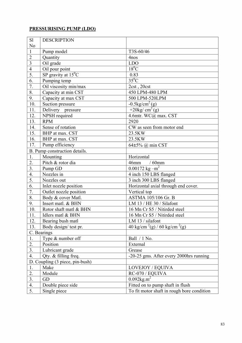
83
PRESSURISING PUMP (LDO)
Sl No
DESCRIPTION
1 Pump model T3S-60/46 2 Quantity 4nos 3 Oil grade LDO 4 Oil pour point 180C 5. SP gravity at 150C 0.83 6. Pumping temp 350C 7. Oil viscosity min/max 2cst , 20cst 8. Capacity at min CST 450 LPM-480 LPM 9. Capacity at max CST 500 LPM-520LPM 10. Suction pressure -0.5kg/cm2 (g) 11. Delivery pressure +20kg/ cm2 (g) 12. NPSH required 4.6mtr. WC@ max. CST 13. RPM 2920 14. Sense of rotation CW as seen from motor end 15. BHP at max. CST 23.5KW 16. BHP at max. CST 23.5KW 17. Pump efficiency 64±5% @ min CST B. Pump construction details. 1. Mounting Horizontal 2. Pitch & rotor dia 46mm / 60mm 3. Pump GD 0.00172 kg –m2
4. Nozzles in 4 inch 150 LBS flanged 5. Nozzles out 3 inch 300 LBS flanged 6. Inlet nozzle position Horizontal axial through end cover. 7. Outlet nozzle position Vertical top 8. Body & cover Matl. ASTMA 105/106 Gr. B 9. Insert matl. & BHN LM 13 / HE 30 / Silafont 10. Rotor shaft matl & BHN 16 Mn Cr S5 / Nitirded steel 11. Idlers matl & BHN 16 Mn Cr S5 / Nitirded steel 12. Bearing bush matl LM 13 / silafont 13. Body design/ test pr. 40 kg/cm 2(g) / 60 kg/cm 2(g) C. Bearings 1. Type & number off Ball / 1 No. 2. Position External 3. Lubricant grade Grease 4. Qty. & filling freq. -20-25 gms. After every 2000hrs running D. Coupling (3 piece, pin-bush) 1. Make LOVEJOY / EQUIVA 2. Module RC-070 / EQUIVA 3. GD 0.092kg.m2
4. Double piece side Fitted on to pump shaft in flush 5. Single piece To fit motor shaft in rough bore condition

84
E.MECHANICAL SEAL 1. Action Single 2. Make DURA / EPIL / BURGMA 3. Module No. & size EB / TYPE 560 / DM3 4. ‘O’ ring spring matl. Viton 5. Rotary Carbon 6. Stationary ring matl. SS 7. Suction press MAX 7kg/cm2 (g) F. SAFETY RELIEF VALVE-INTEGRAL 1. Make TUSHACO 2. Model No. & size TP-A-P-44V 3. Capacity Full 4. Set pressure 5kg/cm2 (g)above delivery pr.
5. Over pressure 3.5kg/cm2 (g) 6. Spring adjust range 15kg/cm2 (g) to 40kg/cm2 (g) PRESSURISING PUMP (LDO) MOTOR
Sl No
DESCRIPTION
1 Application LDO pump 2 Manufacturer BHARAT BIJLEE LTD
Type MD20L233 Frame size 200L
3 Degree of Protection IP 55 4 Gas group II A & IIB
Rated output in kw 30 5 Rated speed in RPM 2955
Rated voltage & variation 415 ± 10% Frequency & variation 50 HZ ± 5%
6
Phases 3 Full load current 50A 7
Starting current 300A Full load efficiency 92.50 % 8
Power factor 0.89 9 Rated torque 9.83 kg-m 10 Load torque NA 11 No load starting time Less than 1 sec. 12 Direction of rotation Bi- directional 13 Bearing make & type DEEP GROOVED SKF-6312DE / 6313
NDE C3 clearance 14 Lubricant recommended & grade Lithium based grease, LL3 of Balmer lawrie 15 Interval of Lubrication(Hrs) 4000hrs 16 Total weight of the motor 260kg 17 Anticipated bearing life 40000hrs.

85
DRAIN OIL PUMP
Sl No
DESCRIPTION
1 Pump model R-20-DG SJ 2 Quantity 2nos 3 Oil grade HFO/LDO/LSHS/HPS 4 Oil pour point 720C 5. SP gravity at 500C 0.83/0.92/0.8555 6. Pumping temp 330C -1300C 7. Oil viscosity min/max 180cst , 500cst 8. Capacity at min CST 67 LPM 9. Capacity at max CST 71 LPM 10. Suction pressure -0.5kg/cm2 (g) 11. Delivery pressure +10kg/ cm2 (g) 12. NPSH required 5mtr. WC@ max. CST 13. RPM 1450 14. Sense of rotation CW as seen from motor end 15. BHP at max. CST 3.25KW 16. BHP at max. CST 4KW 17. Pump efficiency 34±5% @ min CST B. Pump construction details. 1. Mounting Horizontal 2. Pitch & rotor dia NA 3. Pump GD 0.0011 kg –m2
4. Nozzles in 1.5 inch 150 LBS flanged 5. Nozzles out 1.5 inch 300 LBS flanged 6. Inlet nozzle position Horizontal side 7. Outlet nozzle position Side 8. Body & cover Matl. A 216 Gr. WCB 9. Insert matl. & BHN NA 10. Rotor shaft matl SS316/ENB 11. Idlers matl EN6 12. Bearing bush matl SINTERED IRON 13. Body design/ test pr. 20 kg/cm 2(g) / 25 kg/cm 2(g) C. Bearings 1. Type & number off Ball BEARING 2. Position External 3. Lubricant grade Grease 4. Qty. & filling freq. NA D. Coupling (3 piece, pin-bush) 1. Make LOVEJOY / EQUIVA 2. Module RC-042 3. GD 0.013kg.m2
4. Double piece side Fitted on to pump shaft in flush 5. Single piece To fit motor shaft in rough bore condition

86
E.MECHANICAL SEAL 1. Action Single 2. Make EAGLE POONAWALA IND LTD 3. Model No. & size 560 4. ‘O’ ring spring matl. Viton 5. Rotary Carbon 6. Stationary ring matl. SS 7. Suction press MAX 7kg/cm2 (g) F. SAFETY RELIEF VALVE-INTEGRAL 1. Make TYCO SANNER 2. Model No. & size JLT-JOS-E 15J 3. Capacity Full 4. Set pressure 3kg/cm2 (g) above delivery pr. 5. Over pressure 2kg/cm2 (g) 6. Spring adjust range 10kg/cm2 (g) to 20kg/cm2 (g) DRAIN OIL PUMP MOTOR
Sl No
DESCRIPTION
1 Application Drain oil pump 2 Manufacturer Crompton Greaves Ltd
Type Flame proof Frame size E132M
3 Degree of Protection IP 55 4 Gas group II A & IIB
Rated output in kw 5.5 5 Rated speed in RPM 1440
Rated voltage 415 Frequency 50 HZ
6
Phases 3 Full load current 11A 7
Starting current 600% Full load efficiency 84 % 8
Power factor 0.81 9 Rated torque 3.75 kg-m 10 Load torque NA 11 No load starting time 0.25 Sec.

87
TECHNICAL DATA OF BOILER WATER CIRCULATING PUMP 1.1 GENERAL Unit serial Nos: Spare Pump/Motor EP/00/10246 A Customer Order No: 0100618 Customer Order No: (Spare Unit) A500540 Service: Boiler Water Circulating Pump with Motor
below Pump. Number Supplied: 12 + 1 Spare Electrical: 3300V – 3 phase – 50Hz CHARACTERISTICS Type: Single Suction – Double Discharge Size: (2x13)x16x19H Design Pressure: 211.0 kg/cm2 g Design Temperature: 369° C Suction Pressure: 195.24 kg/cm2 N.P.S.H. required: 14 m (3% Head drop at cold at duty) Quantity Pumped: 3133 m3/hr Differential Head: 31.1 Specific Gravity: 0.565 Hydraulic Test Pressure: 316.5 kg/cm2 g Pump Efficiency: 83% Cold 83% Hot KW Absorbed 319.9 Cold 180.7 Hot
1.2 MOTOR CHARACTERISTICS
Type Wet Stator Squirrel Cage Induction Output 354 kW (475HP) Service Factor 1.0 Winding Insulation XLP Speed 1450 RPM Motor Case Design Temperature 343°C Motor Efficiency Hot Duty Cold Test KW Input 88.8% 90.4% Power Factor 203.5 353.9 Overall Efficiency 0.70 0.81 Full Load Current 84 amps Motor Starting Current 240 amps

88
1.3 CLEARANCES & SETTINGS
Initial Maximum Impeller Wear Ring Clearance Diametrical: 1.46-1.58 2.03 Reverse Thrust Wear Ring Clearance Diametrical:
0.35-0.45 0.68
Journal Bearing clearance diametrical Rotor End Float:
0.25-0.39 0.2-0.3
0.6 0.51
Impeller Setting (Dimension ‘A’): 563.5/562.8 1.4 INSTRUMENTATION :
Temperature Switches: Asheroft Model T.461-T20-030-69C-XNH:
20-950C with 6096mm capacity. 15amp. 125 to 250 Volt AC.
Thermometer : Asheroft Model 600A-03-C41-B01-A1-L07-BS-XNG 0-1200C-CD1
Pressure Gauge: Asheroft Model 60-1379SSL-04L-XNH-XNG 0-250 Kg/cm2-CD1.
Flowmeter: KDG Mobrey Series 250 Rotameter Model 250-50-CX-M12-TO-S6-Z6 Relay Mains supply: 220 V 50/60 Hz. Contact Cut Off Capacity: Max 250V/4A/500VA
Thermocouples: Type ‘KK’ Ungrounded 1.5 WEIGHTS (Approximate) Pump Case 3425 kg. Complete Motor Assembly 7443 kg Heat Exchanger 410 kg TOTAL 11278 kg

89
TECHNICAL DATA OF SOOT BLOWERS ALL DIMENSIONS ARE IN MILLIMETERS.
TYPE OF SOOT BLOWERS SL.
NO DESCRIPTION
WB IE LRD IIE 01. BLOWER NUMBERS 1 To 88 105R to 108L 109R to 124L 125R to 138L
02. TRAVEL IN MM 305 9700 9700 9700 03. DEAD TRAVEL IN MM - 350 350 350 04. NOZZLE SIZE IN MM / NO. OFF NOZZLES. φ26/1 φ32/2 φ25/2 φ25/2 05. BLOWER PRESSURE IN KG/CM2(G) 11 12.5 12.5 10 06. SPEED OF TRAVEL IN MPM ROTARY /RPM 6.1 0.7 1.55 5.87 1.55 5.87 1.55 5.8707. BLOWING RATE PER GROUP IN KG/MIN 89 303.2 185 151 08. BLOWER TIME PER GROUP IN MIN. 1.4 12.06 12.06 12.06 09. OPERATING TIME PER GROUP IN MIN. 1.5 12.5 12.5 12.5 10. OPERATING TIME PER CYCLE IN MIN. 66 25 100 87.5 11. STEAM CONSUMPTION PER GROUP IN KG. 125 3657 2231 1821 12. STEAM CONSUMPTION PER CYCLE IN KG. 5500 3657 17848 12747 13. CYCLES PER DAY (ASUMED) 3 3 3 3 14. STEAM CONSUMPTION PER DAY IN KG. 16500 10971 53544 38241 15. BLOWING ANGLE. 360° 360° 360° 360° (PER DAY) TOTAL STEAM CONSUMPTION IN KGS = 1189256 LRD IIE : LONG RETRACTABLE SOOT BLOWER ELECTRICALLY OPERATED. WB IE: WALL BLOWER ELECTRICALLY OPERATED.
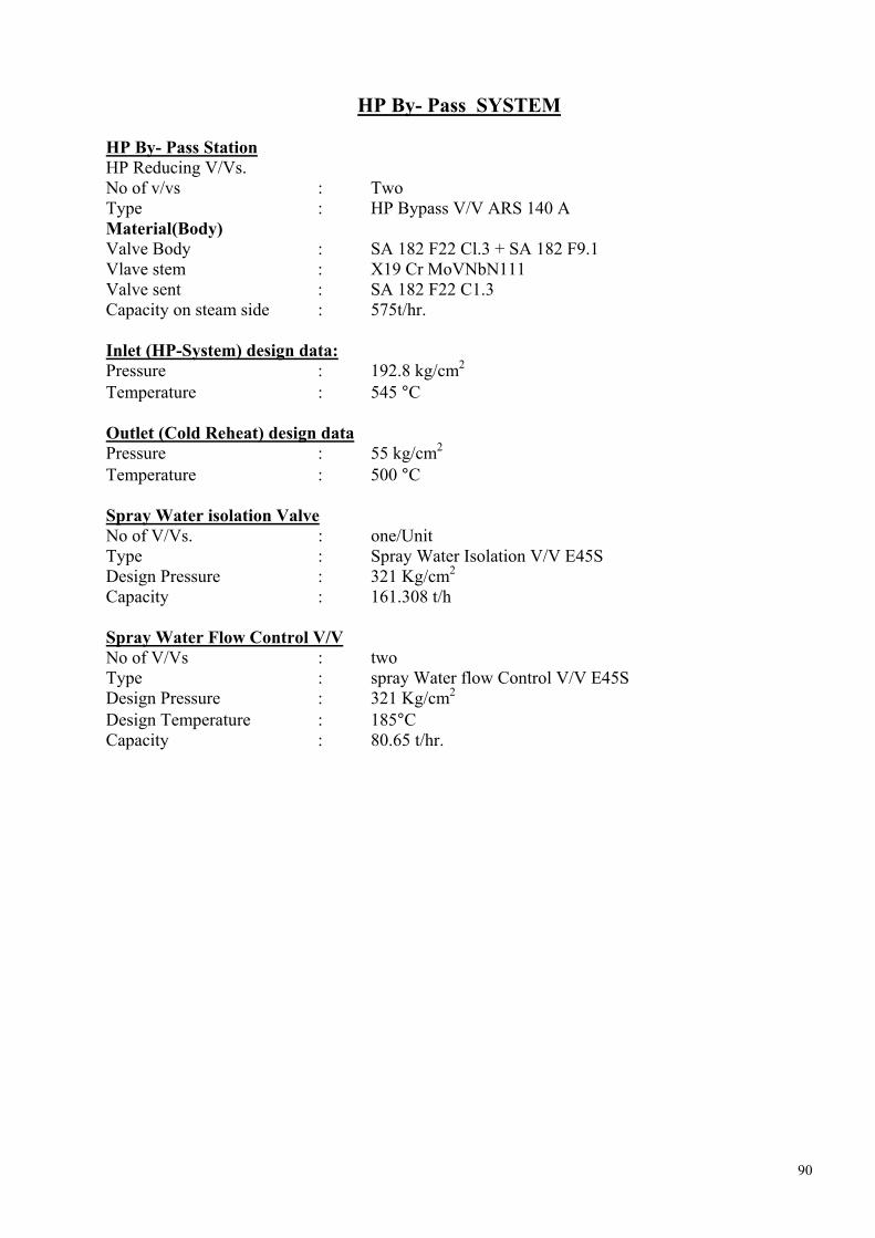
90
HP By- Pass SYSTEM HP By- Pass Station HP Reducing V/Vs. No of v/vs : Two Type : HP Bypass V/V ARS 140 A Material(Body) Valve Body : SA 182 F22 Cl.3 + SA 182 F9.1 Vlave stem : X19 Cr MoVNbN111 Valve sent : SA 182 F22 C1.3 Capacity on steam side : 575t/hr. Inlet (HP-System) design data: Pressure : 192.8 kg/cm2 Temperature : 545 °C Outlet (Cold Reheat) design data Pressure : 55 kg/cm2 Temperature : 500 °C Spray Water isolation Valve No of V/Vs. : one/Unit Type : Spray Water Isolation V/V E45S Design Pressure : 321 Kg/cm2 Capacity : 161.308 t/h Spray Water Flow Control V/V No of V/Vs : two Type : spray Water flow Control V/V E45S Design Pressure : 321 Kg/cm2 Design Temperature : 185°C Capacity : 80.65 t/hr.
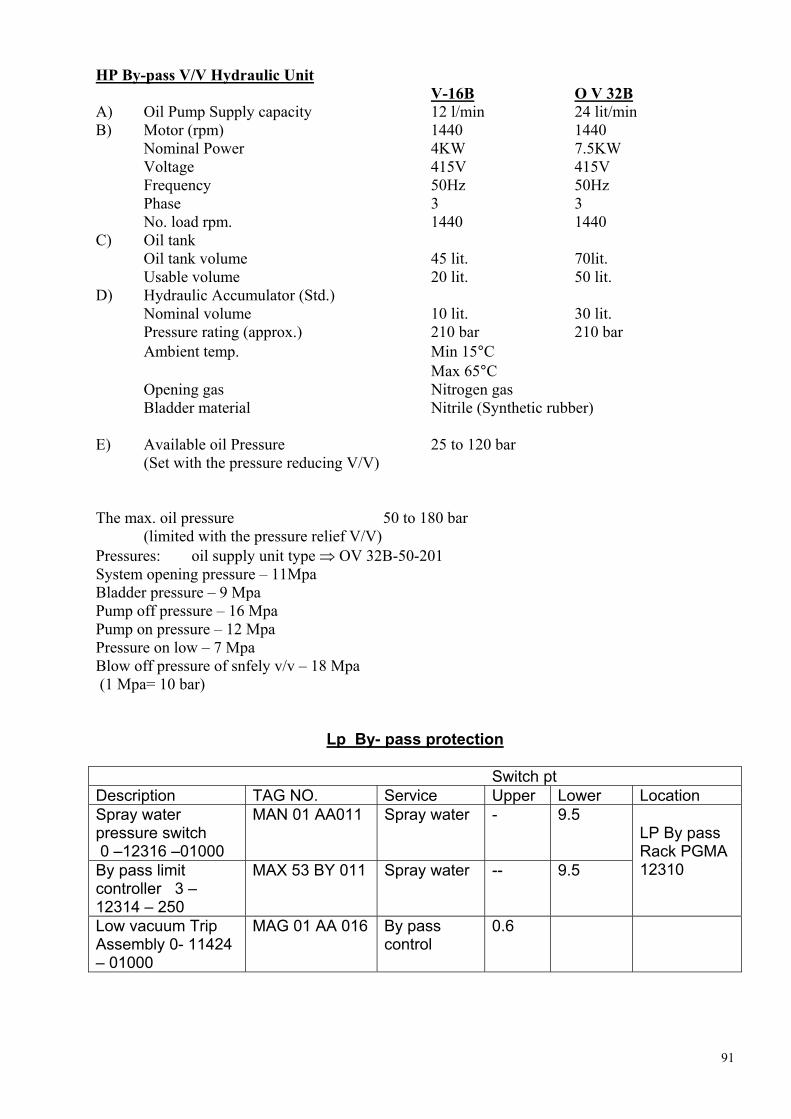
91
HP By-pass V/V Hydraulic Unit V-16B O V 32B A) Oil Pump Supply capacity 12 l/min 24 lit/min B) Motor (rpm) 1440 1440 Nominal Power 4KW 7.5KW Voltage 415V 415V Frequency 50Hz 50Hz Phase 3 3 No. load rpm. 1440 1440 C) Oil tank Oil tank volume 45 lit. 70lit. Usable volume 20 lit. 50 lit. D) Hydraulic Accumulator (Std.)
Nominal volume 10 lit. 30 lit. Pressure rating (approx.) 210 bar 210 bar Ambient temp. Min 15°C Max 65°C Opening gas Nitrogen gas Bladder material Nitrile (Synthetic rubber)
E) Available oil Pressure 25 to 120 bar (Set with the pressure reducing V/V) The max. oil pressure 50 to 180 bar (limited with the pressure relief V/V) Pressures: oil supply unit type ⇒ OV 32B-50-201 System opening pressure – 11Mpa Bladder pressure – 9 Mpa Pump off pressure – 16 Mpa Pump on pressure – 12 Mpa Pressure on low – 7 Mpa Blow off pressure of snfely v/v – 18 Mpa (1 Mpa= 10 bar)
Lp By- pass protection
Switch pt Description TAG NO. Service Upper Lower Location Spray water pressure switch 0 –12316 –01000
MAN 01 AA011 Spray water - 9.5
By pass limit controller 3 – 12314 – 250
MAX 53 BY 011 Spray water -- 9.5
LP By pass Rack PGMA 12310
Low vacuum Trip Assembly 0- 11424 – 01000
MAG 01 AA 016 By pass control
0.6

92
Safety Valves
Value set pr. kg/cm2 (g)
Location Nos. Valve Tag No.
Type of safety valve
Open Close
% of Blow down
Relieving capacity/Valve (Kg/hr)
Total % of Evaporation
Boiler drum
6 SV1 SV2 SV3 SV4 SV5 SV6
1750 WB 1750 WB 1740 WB 1740 WB 1740 WB 1740 WB
207.0 209.0 211.1 211.1 213.2 213.2
198.7 198.6 200.5 200.5 202.5 202.5
4.0 5.0 5.0 5.0 5.0 5.0
210774 212800 256157 256157 258692 258692
109.14
2 SV7 SV8
1740WD 188.5 181.3 3.8 187441
ERV(SV9) ERV(SV10)
1538VX-10W 185.5 180.5 2.7 116388
Super Heater
5 ERV(SV11) ERV(SV12) ERV(SV13)
1538VX-10W 186.6 181.0 3.0 94195
30.76
SV14 SV15
1786WB 52.4 49.8 5.0 207230 CRH 4
SV16 SV17
1786WB 54.0 51.3 5.0 213910
SV18 SV19
1786WD 49.4 46.9 5.0 164118 4
SV20 SV21
1786WD 50.9 48.4 5.0 169223
104.39
ERV(SV22) ERV(SV23)
1525VX 48.4 47.1 2.7 122011
HRH
4
ERV(SV24) ERV(SV25)
1525VX 48.9 47.6 2.7 123246
33.93
SB 1 SV26 1811LC 6X 40.0 38.4 4.0 30005 ----

93
TECHNICAL SPECIFICATION FOR COOLING WATER BOOSTER PUMP.
SL.NO DESCRIPTION 1. Project Talcher 4x500 MW 2. Customer NTPC 3. No.of pumps per boiler 2(1 working + 1standby) 4. Total no. of pumps 8 5. Type Horizontal radially spilt, volute casing
pumps. 6. Medium Cooling water 7. Rated temperature 50 Deg C 8. Suction pressure 4.5 kg/cm sq (g) 9. Discharge pressure 12.0kg/cm sq (g) 10. Diff. Head to be developed 75 MLC 11. Rated flow
Design flow 68 t/hr 72 t/hr
12. Material of construction Cast carbon steel 13. Rated speed 2960 rpm 14. Suction pipe size Nb 100 15. Discharge pipe size Nb 100 16. End connection Hanged oiling as per ANSI 16.5 17. Power supply 415 V,3-phase

94
ACW SYSTEM Sl No
DESCRIPTION
1.01 Auxiliary Cooling Water Pumps Quantity 2 Working + 1 Standby Manufacture M/S Mather & Platt(India) Ltd.,Pune. Model No. 16/20 LONO Type Centrifugal, Horizontal Split Casing. Design Capacity 2100 M3
/Hr Rated TDH 14MLC Rated RPM 980 RPM Shut off head 23.5 MLC Efficiency at rated speed 87.55 % 1.02 Self Cleaning filters Quantity 1 Working + 1Standby Manufacturer M/S GEA Ecoflex – GmbH Normal flow 4200 M3
/Hr Pressure drop in clean condition < 100 mbar 1.03 Plate Heat Exchangers for TG Auxiliaries Quantity 2 Working + 1 Standby Manufacture M/S GEA Ecoflex – GmbH Plate Material SS 316 No of plates 456 Flow rate 1500 M3
/Hr Inlet water temperature 36°C Out let water temperature 41.1°C(In Clean condition) 40.6°C(In Fouled condition) 1.04 Plate Heat Exchangers for Boiler Auxiliaries Quantity 1 Working + 1 Standby Manufacture M/S GEA Ecoflex – GmbH Plate Material SS 316 No of plates 286 Flow rate 575 M3
/Hr Inlet water temperature 36°C Out let water temperature 42 °C(In Clean condition) 41.5°C(In Fouled condition)

95
ECW SYSTEM 1.05 ECW Pumps for TG Auxiliaries. Quantity 2 Working + 1 Standby (for one unit) Manufacture M/S Mather & Platt(India) Ltd.,Pune. Model No. 300/400 BST Type Centrifugal, Horizontal Split Casing. Design Capacity 1630 M3
/Hr Rated TDH 33MLC Rated Speed 1480 RPM Shut off head 52 MLC Efficiency at rated speed 87.45 % 1.05 ECW Pumps for Boiler Auxiliaries. Quantity 1 Working + 1 Standby (for one unit) Manufacture M/S Mather & Platt(India) Ltd.,Pune. Model No. 200/250 CST Type Centrifugal, Horizontal Split Casing. Design Capacity 625 M3
/Hr Rated TDH 44MLC Rated Speed 1480 RPM Shut off head 56 MLC Efficiency at rated speed 83.20 % 1.03 Plate Heat Exchangers for TG Auxiliaries Quantity 2 Working + 1 Standby Manufacture M/S GEA Ecoflex – GmbH Plate Material SS 316 No of plates 456 Flow rate 1500 M3
/Hr Inlet water temperature 42.6°C Out let water temperature 37.5°C(In Clean condition) 38.0°C(In Fouled condition) 1.04 Plate Heat Exchangers for Boiler Auxiliaries Quantity 1 Working + 1 Standby Manufacture M/S GEA Ecoflex – GmbH Plate Material SS 316 No of plates 286 Flow rate 575 M3
/Hr Inlet water temperature 43.5°C Out let water temperature 37.5 °C(In Clean condition) 38.0°C(In Fouled condition)

96
SECONDARY AIRPREHEATERS
HEATER SIZE : 30VIM 2000- 2 NOS / BLR HEATER SERIAL NO. : 0493 TO 0500
SL. DESCRIPTION SPECIFICATION 1. HEATING ELEMENTS
a) Hot end heating elements: Element type Element height Material
0.8 mm – DU profile 850 mm carbon Steel
b) Hot int. heating elements: Element type. Element height Material
0.8 mm –DU profile 850 mm carbon steel
c) Cold end heating elements: Element type Element height Material
1.2 mm –NF6 profile 300 mm Corten steel
2 ROTOR SEALS Radial seals – hot end Radial seals – cold end Axial seals By-pass seals Rotor post seals HE & CE
2.5 mm Corten A 2.5 mm Corten A 2.5 mm Corten A 1.6 mm Corten A 6 mm – IS 2062
3 ROTOR DRIVE ESSY. Motor –TEFC (Main & Stand by) Speed reducer coupling
Crompton greaves, 18.5 KW, 415 V, 3 PH, 50Hz, 1460 rpm, frame – 180L. class-F Type – II, 3 input, down shaft Seisa / Japan 12.75 FCU – Pembril make.
4 AUXILIARY DRIVE Air motor Coupling Solenoid valve Pressure switch Filter & Lubricator
Ingersolrand, Model IR92- RA022 Bibby coupling type 124 A ASCO / AVCON 230 V, IPH, AC, 50 Hz- 1” BSP 1/ 4” NPT (F), 0-10kg/cm2 1” BSP – Veljohn / Norgren
5 ROTOR STOPPAGE ALARM
Go – Switch
Alsthom (ABB) – USA
6 BEARINGS
Guide bearing
Thermostat
Support bearing
RTD
Sph. Roller 23072/CCK/C3/W33
3/8” NPT – BURLING
Spherical roller thrust 294/750 E
1” BSP (M) Duplex. –Theremowell
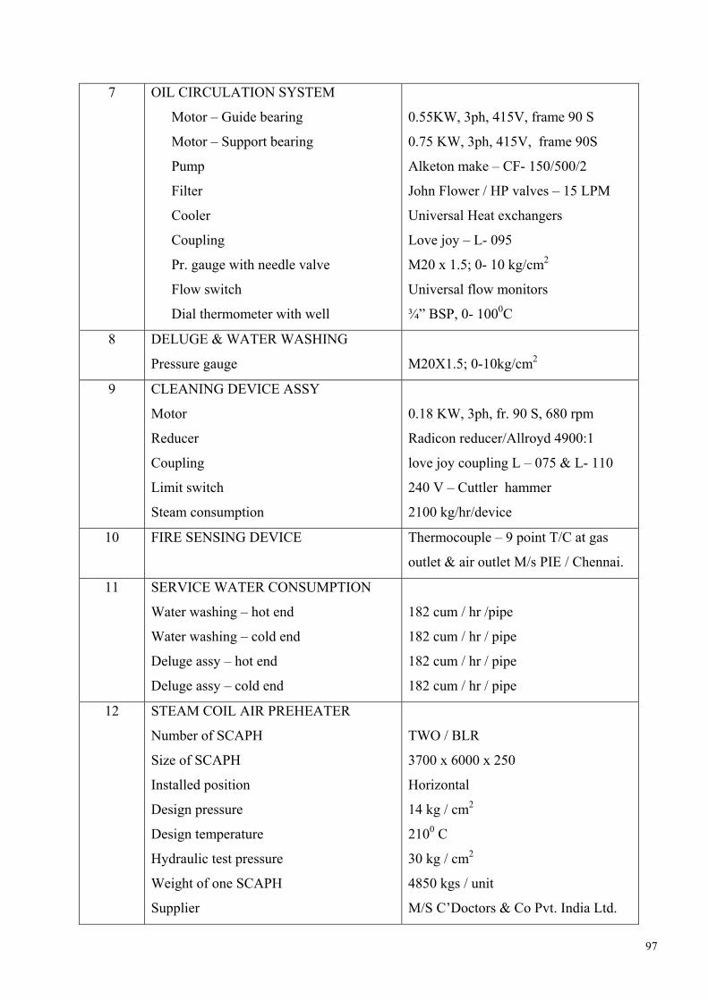
97
7 OIL CIRCULATION SYSTEM
Motor – Guide bearing
Motor – Support bearing
Pump
Filter
Cooler
Coupling
Pr. gauge with needle valve
Flow switch
Dial thermometer with well
0.55KW, 3ph, 415V, frame 90 S
0.75 KW, 3ph, 415V, frame 90S
Alketon make – CF- 150/500/2
John Flower / HP valves – 15 LPM
Universal Heat exchangers
Love joy – L- 095
M20 x 1.5; 0- 10 kg/cm2
Universal flow monitors
¾” BSP, 0- 1000C
8 DELUGE & WATER WASHING
Pressure gauge
M20X1.5; 0-10kg/cm2
9 CLEANING DEVICE ASSY
Motor
Reducer
Coupling
Limit switch
Steam consumption
0.18 KW, 3ph, fr. 90 S, 680 rpm
Radicon reducer/Allroyd 4900:1
love joy coupling L – 075 & L- 110
240 V – Cuttler hammer
2100 kg/hr/device
10 FIRE SENSING DEVICE Thermocouple – 9 point T/C at gas
outlet & air outlet M/s PIE / Chennai.
11 SERVICE WATER CONSUMPTION
Water washing – hot end
Water washing – cold end
Deluge assy – hot end
Deluge assy – cold end
182 cum / hr /pipe
182 cum / hr / pipe
182 cum / hr / pipe
182 cum / hr / pipe
12 STEAM COIL AIR PREHEATER
Number of SCAPH
Size of SCAPH
Installed position
Design pressure
Design temperature
Hydraulic test pressure
Weight of one SCAPH
Supplier
TWO / BLR
3700 x 6000 x 250
Horizontal
14 kg / cm2
2100 C
30 kg / cm2
4850 kgs / unit
M/S C’Doctors & Co Pvt. India Ltd.

98
13 SET POINTS
Oil flow switch – Guide bearing assy
Oil flow switch – Support bearing assy
Pressure switch
Before solenoid valve
After solenoid valve
Thermostat – Guide bearing assy
Thermostat – support bearing assy
RTD Alarm – Guide bearing assy
RTD Alarm – Support bearing assy
Fire Sensing device:
Low Temperature
High Temperature
3LPM
7 LPM
5 KG/ CM 2 (g)
3 KG / CM2 (g)
400 C
40 0 C
70 0 C
70 0 C
50 0 C
450 0C
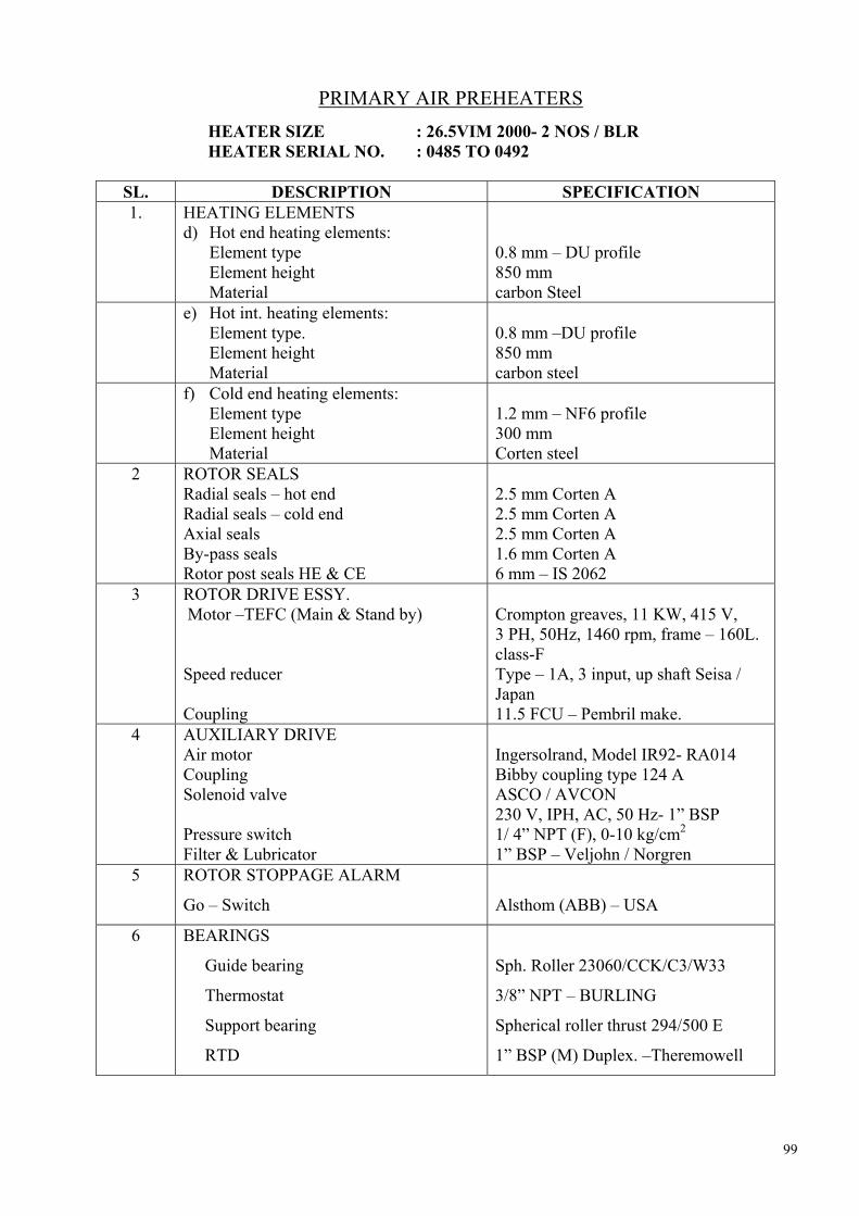
99
PRIMARY AIR PREHEATERS HEATER SIZE : 26.5VIM 2000- 2 NOS / BLR HEATER SERIAL NO. : 0485 TO 0492
SL. DESCRIPTION SPECIFICATION 1. HEATING ELEMENTS
d) Hot end heating elements: Element type Element height Material
0.8 mm – DU profile 850 mm carbon Steel
e) Hot int. heating elements: Element type. Element height Material
0.8 mm –DU profile 850 mm carbon steel
f) Cold end heating elements: Element type Element height Material
1.2 mm – NF6 profile 300 mm Corten steel
2 ROTOR SEALS Radial seals – hot end Radial seals – cold end Axial seals By-pass seals Rotor post seals HE & CE
2.5 mm Corten A 2.5 mm Corten A 2.5 mm Corten A 1.6 mm Corten A 6 mm – IS 2062
3 ROTOR DRIVE ESSY. Motor –TEFC (Main & Stand by) Speed reducer Coupling
Crompton greaves, 11 KW, 415 V, 3 PH, 50Hz, 1460 rpm, frame – 160L. class-F Type – 1A, 3 input, up shaft Seisa / Japan 11.5 FCU – Pembril make.
4 AUXILIARY DRIVE Air motor Coupling Solenoid valve Pressure switch Filter & Lubricator
Ingersolrand, Model IR92- RA014 Bibby coupling type 124 A ASCO / AVCON 230 V, IPH, AC, 50 Hz- 1” BSP 1/ 4” NPT (F), 0-10 kg/cm2 1” BSP – Veljohn / Norgren
5 ROTOR STOPPAGE ALARM
Go – Switch
Alsthom (ABB) – USA
6 BEARINGS
Guide bearing
Thermostat
Support bearing
RTD
Sph. Roller 23060/CCK/C3/W33
3/8” NPT – BURLING
Spherical roller thrust 294/500 E
1” BSP (M) Duplex. –Theremowell
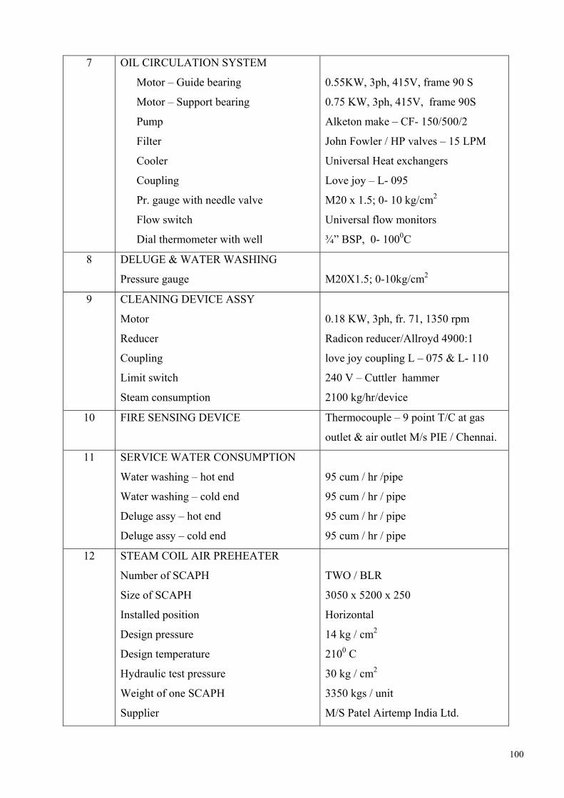
100
7 OIL CIRCULATION SYSTEM
Motor – Guide bearing
Motor – Support bearing
Pump
Filter
Cooler
Coupling
Pr. gauge with needle valve
Flow switch
Dial thermometer with well
0.55KW, 3ph, 415V, frame 90 S
0.75 KW, 3ph, 415V, frame 90S
Alketon make – CF- 150/500/2
John Fowler / HP valves – 15 LPM
Universal Heat exchangers
Love joy – L- 095
M20 x 1.5; 0- 10 kg/cm2
Universal flow monitors
¾” BSP, 0- 1000C
8 DELUGE & WATER WASHING
Pressure gauge
M20X1.5; 0-10kg/cm2
9 CLEANING DEVICE ASSY
Motor
Reducer
Coupling
Limit switch
Steam consumption
0.18 KW, 3ph, fr. 71, 1350 rpm
Radicon reducer/Allroyd 4900:1
love joy coupling L – 075 & L- 110
240 V – Cuttler hammer
2100 kg/hr/device
10 FIRE SENSING DEVICE Thermocouple – 9 point T/C at gas
outlet & air outlet M/s PIE / Chennai.
11 SERVICE WATER CONSUMPTION
Water washing – hot end
Water washing – cold end
Deluge assy – hot end
Deluge assy – cold end
95 cum / hr /pipe
95 cum / hr / pipe
95 cum / hr / pipe
95 cum / hr / pipe
12 STEAM COIL AIR PREHEATER
Number of SCAPH
Size of SCAPH
Installed position
Design pressure
Design temperature
Hydraulic test pressure
Weight of one SCAPH
Supplier
TWO / BLR
3050 x 5200 x 250
Horizontal
14 kg / cm2
2100 C
30 kg / cm2
3350 kgs / unit
M/S Patel Airtemp India Ltd.

101
13 SET POINTS
Oil flow switch – Guide bearing assy
Oil flow switch – Support bearing assy
Pressure switch
Before solenoid valve
After solenoid valve
Thermostat – Guide bearing assy
Thermostat – support bearing assy
RTD Alarm – Guide bearing assy
RTD Alarm – Support bearing assy
Fire Sensing device:
Low Temperature
High Temperature
3 LPM
7 LPM
5 KG/ CM 2 (g)
3 KG / CM2 (g)
400 C
35 0 C
70 0 C
70 0 C
50 0 C
450 0C

102
AIR CONDITION ING SYSTEM DATA SHEET FOR SCREEW COMPRESSOR CHILLING UNIT Sl.No. Description Screw compressor chilling unit
a Name address of Manufacturer CARRIER China Limited b Make and model CARRIER , 30HXC345 c Number offered (working +stand
by ) 0+2
d Rated capacity (TR) at operating condition
315
e Operating weight 5870kgs f Refrigerant i) Name R 134A ii) Quantity 220 KGS g Operating Condition i) Evaporating Temperature 20°C ii) Condensing Temperature 42 °C h Type of condenser cooling Water cooled i Operating sped 2940 RPM j No. of stage 10 k Power consumption (KW/TR) 100% Load 0.89 90% Load 0.88 80 Load 0.81 70% Load 0.76 60% Load 0.74 50% Load 0.64 40 Load 0.64 30% Load 0.6 20% Load 0.58 10% Load 0.59 n Motor rating (KW) ( Max power
input to each Compressor) 79
o Mode of Start DOL p No. of Starter 2nos q Overall Dimension in mm
(L ×W×H) 4490 × 980 × 2163
r Tube cleaning space required 4120 mm on left side , 1000mm on right side s Type of capacity control Solenoid Operated t Range of capacity variation 100-10% u Type of Bearing TRB

103
2 COMPRESSER a No. of compressor 4 b Type of compressor Screw c Motor raring (KW) to each
compressor 79
d Power consumption per chilling machine
283 KW
e Main Helical Rotor Holroyd (Steel C1141 as per ASTM A 29) f Gear Nixon g Housing YLC (Yileng carrier) h Main bearing SKF 3 CONDSER a Quantity per chilling machine 1 b Manufacture CARRIER c TYPE Shell & Tube , Flodded d No. of pass 2 e Shell Material MS f Shell Diameter 55mm OD g Shell Thickness(mm) 8 h Shell length 4083mm i Tube Material / Size Copper/1” j No of Tubes 137 k No. of fins Integrally finned l Tube thickness 1.3mm m Water flow 238 cum /hr n Water velocity 2.5m/sec. o Pressure drops through Condenser 0.75kg/cm2 p Water In /Out Temperature 32 0C /37 0C q Fouling Factor 0.0002 MKS Unit 4 CHILLER a manufacture CARIER b Quantity per chilling machine 1 c No. of pass 2 d Type Shell & Tube , Flooded e Shell thickness 6mm f Tube size (mm) 18.9mm OD g No. of tube 268 h Tube thickness (mm) 1.2mm i Chilled water QTY (CU.M/HR) 191 cum/hr j Chilled Water Inlet /Outlet 12 0C/7 0C k Water velocity in Tube 2.1m/sec. l Pressure drop through Chiller 0.49 Kg/cm2 m Fouling Factor 0.0001 MKS Unit 5 TESTING PRESSURE a Condenser i) Tube side 15Kg/cm2 ii) Shell side 26Kg/cm2 b Chiller i) Tube side 15Kg/cm2 ii) Shell side 26Kg/cm2

104
DATA SHEET FOR VAPOUR ABSORPTION MACHINE
SL. No.
ITEM Datas
Number offered 2 Nominal capacity (TR) 400 NTR Actual capacity (TR) at operating condition 300 TR Model No. C213 E+ Name and address of manufacture THERMAX LTD.
CHINCHWAD PUNE Operating Weight 13.7 TONS Refrigerant WATER Operating condition ( Condensing/ Evaporating
Temp.) 40.9/5.2 DegC
Absolute pressure in i) absorber 6.66mm Hg ii) Evaporator 6.66mm Hg ii) Condenser 57.88mm Hg-LTG iv) Generator 712.55mm Hg-HTG Steam consumption 100% 1298 kg/hr (guaranteed
parameter) 90% 1168 kg/hr( Indicative only ) 80% 1038 kg/hr(indicative only ) 70% 909 kg/hr( Indicative only ) 60% 778 kg/hr( Indicative only ) 50% 649 kg/hr( Indicative only ) 40% 520 kg/hr( Indicative only ) 30% 390 kg/hr( Indicative only ) 11 Electric power Consumption i) Refrigerant pump 0.5kw ii) Solution pump 4.5 kw Iii ) Vacuum pump 0.46 kw 12 Overall dimension in mm( L× W× H) 4770 × 2405 × 2740 mm 13 Tube clearing space required 4505 mm 14 Steam inlet temperature &pressure 10kg /cm2 g at 183.2 °C 15 Condensate temperature & pressure 80-100 °C / 4m.w.c. 16 Pressure reducing and de-superheatring station for
steam provided? Yes
17 No. of heat exchangers Two Regenerative Heat Exchangers
18 Decrystallissation Circuit / dilution Circuit provided ? Yes
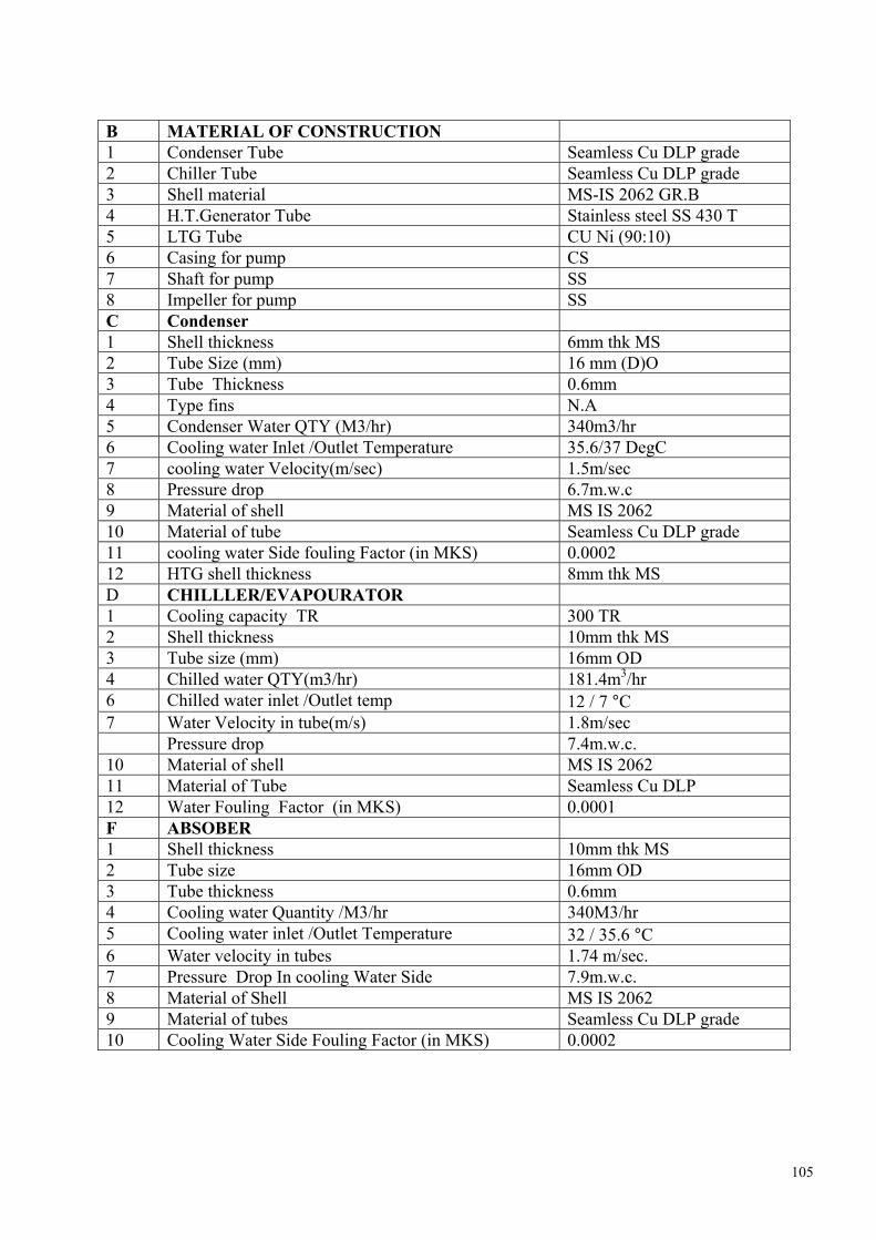
105
B MATERIAL OF CONSTRUCTION 1 Condenser Tube Seamless Cu DLP grade 2 Chiller Tube Seamless Cu DLP grade 3 Shell material MS-IS 2062 GR.B 4 H.T.Generator Tube Stainless steel SS 430 T 5 LTG Tube CU Ni (90:10) 6 Casing for pump CS 7 Shaft for pump SS 8 Impeller for pump SS C Condenser 1 Shell thickness 6mm thk MS 2 Tube Size (mm) 16 mm (D)O 3 Tube Thickness 0.6mm 4 Type fins N.A 5 Condenser Water QTY (M3/hr) 340m3/hr 6 Cooling water Inlet /Outlet Temperature 35.6/37 DegC 7 cooling water Velocity(m/sec) 1.5m/sec 8 Pressure drop 6.7m.w.c 9 Material of shell MS IS 2062 10 Material of tube Seamless Cu DLP grade 11 cooling water Side fouling Factor (in MKS) 0.0002 12 HTG shell thickness 8mm thk MS D CHILLLER/EVAPOURATOR 1 Cooling capacity TR 300 TR 2 Shell thickness 10mm thk MS 3 Tube size (mm) 16mm OD 4 Chilled water QTY(m3/hr) 181.4m3/hr 6 Chilled water inlet /Outlet temp 12 / 7 °C 7 Water Velocity in tube(m/s) 1.8m/sec Pressure drop 7.4m.w.c. 10 Material of shell MS IS 2062 11 Material of Tube Seamless Cu DLP 12 Water Fouling Factor (in MKS) 0.0001 F ABSOBER 1 Shell thickness 10mm thk MS 2 Tube size 16mm OD 3 Tube thickness 0.6mm 4 Cooling water Quantity /M3/hr 340M3/hr 5 Cooling water inlet /Outlet Temperature 32 / 35.6 °C 6 Water velocity in tubes 1.74 m/sec. 7 Pressure Drop In cooling Water Side 7.9m.w.c. 8 Material of Shell MS IS 2062 9 Material of tubes Seamless Cu DLP grade 10 Cooling Water Side Fouling Factor (in MKS) 0.0002

106
F Purge Unit 1 Type automatic/manual Form vessel to storage tank –
automatic and storage tank to atmosphere - manual through vacuum pump
2 Name of manufacture THERMAX. –Hind Hivac (Purge Pump Only)
3 Model number ED – 12 4 Type of pump Direct Rotary Drive ,double
Stage 5 Capacity of vacuum pump 200 ltrs/min. 6 Head of vacuum pump N.a. 7 Number offered per vapour absorption machine One 8 drive motor rating 0.37 kw G Refrigetoerant reciurculation pump 1 Name of manufacture
TEIKOKU(JAPAN)
2 Model number
L 126 A 4G0406 SB
3 Capacity 15m3/hr 4 Total Dynamical Head 3m 5 Number offered 01/machine 6 Drive motor Rating 0.3 kw 7 speed of pump 140 rpm 8 Type of pump Canned Motor pump H Lithium Bromide re-circulation pump 1 Name of manufacture TEIKOKU(JAPAN) 2 Model Number L 316 C4 DG 0510 SF 3 Capacity 18 m3/hr 4 Total Dynamical Head 16.5m 5 Number offered 1 / machine 6 Drive motor Rating 3.7 kw 7 Speed of pump 2880 rpm 8 Type of pump Canned Motor Pump I Lithium Bromide Solution 1 First charge of lithium bromide provided Yes 2 Quantity of First charge 1900kg

107
TECHINICAL DATA SHEET FOR RECIPORCATING REFRIGERANTCOMPREESSOR
FOR ESP – VFD BUILDING
1. 1.1
GENERAL AREAS BEING AIRCONDITIONED
ESP/VFD BUILDING CONTROL ROOM
1.2 DESIGNATION 1.3 MALKE/ MODEL NUMBER ACCEL / SMC –6-100 XL 1.4 TYPE OF COMPRESSOR OPEN TYPE
RECICIPROCATING (V- BELT DRIVEN)
1.5 NUMBER REQUIRED (WORKING +STAND BY)
8 Nos. (4W + 4S)
1.6 STARTING IOF COMPREESOR DOL STARTING IN UNLOADED CONDITION
1.7 Restarting (after tripping ) on LP cutout Yes ( Automatic) 1.8 Overall space required for compressor and
moter (L×W×H) Mm 1788* 870*12332 (H)
1.9 Total weight Kg - compressor with accessories 970kg - motor 740 kg - Total weight 1710kg 1.10 Dynamical load of compressor and motor
assemble Kg 428kg
1.11 Refrigerant used R- 22 2.0 TECHICAL DATA 2.1 OPERATING CONDITIONS - Evaporating temperatures °C 1.5 °C -Condensing Temperature °C 40.0 °C - Operating speed RPM 1106 2.2 Capacity at operating condition TR 75.01(263.8kw) 2.3 Input power at shaft at operating condition KW 55.7 2.4 Maximum speed of the compressor Rpm 1200
2.5 Capacity at maximum speed at operating
condition TR 81.4 TR (286.2kw)
2.6 Input power at shaft at maximum speed Kw 60.43 2.7 Degree of sub cooling on which the above
capacitys are based 0c 2°C

108
2.8 CAPACITY CONTROL - Capacity control in steps of % - Shaft input power at part loads 33 % 66% 100%
33% – 18.5 kw 66% -37 kw 100% - 55.7 kw
2.9 Motor - - Rating KW 75 - Speed / No of pole RPM 1483 / 4p - Frame size SC 280 S ( KEC make) 2.10 Maximum permissible operating pressure Kg/cm2 15.6 2.11 Test pressure Kg/cm2 21 2.12 First charge of refrigerant provided for the
whole system Kg Yes
2.13 Make and grade of oil used Seetul N 68 /EQV 2.14 First charge of oil LTR 26 liters 3.0 CONSTRUCTION 3.1 No. of cylinders 6 3.2 Bore X stroke of cylinder (L× B) Mm 100mm ×100mm 3.3 Arrangement of cylinders ‘W’ type 3.4 Swept volume at operating speed 311 m3/Hr 3.5 Piston speed at operating system M/SEC
. 3.69
3.6 Clearance mm 0.8mm 3.7 Volumetric efficiency % 78 3.8 Lubrication details Forced feed lubrication

109
TECHINCAL DATA SHEET FOR CONDENSER FOR ESP & VFD CONTROL ROOM SL.NO. 1.0 General 1.1 Service Condenser cooling water 1.2 Location ESP/ VFD Building 1.3 Make / model number ABB/ KTHX- 16 1.4 Type of condenser Water cooled – Shell and
tube 1.5 Number ( working +standby ) 8 (4 W + 4S) 1.6 Overall size OD (mm) × length (m) 500 × 2693 ( Approx.) 1.7 Weight - When empty Kg 930 - With refrigerant fully charged Kg 125 1.8 Condensing Temperature 0 C 40.5 0 C 1.9 Refrigerant storage capacity kg 200-260 (Approx) 2.0 Construction details 2.1 Shell material MS 2.2 Shell thickness mm 8mm 2.3 Shell diameter (ID) mm 484 2.4 Tube material Copper BS – 2871 2.5 Tube size mm 19.05 2.6 Tube thickness 18 Swg. 2.7 Tube length 2250 mm 2.8 No. of tubes 231 2.9 No. of passes 4 210 No. tubes per pass 57 (Approx.) 2.1 Fine type Integral part of tube 212 No of fines per inch 19 2.13 Water box material ( End cover) C.I /IS –210 2.14 Fin material Copper 3.0 Technical data 3.1 Circulating water quantity required m3/h 60 3.2 Water velocity in tubes m/s 1.34 3.3 Water inlet /outlet in temperature 0 C 32 0 C / 370 C 3.4 Heat rejection rate KW 325.3 3.5 Heat transfer area - Refrigerant side m2 76 - Water side m2 26.4 3.6 Water side pressure drop KPA / 40 (0.4kg/cm2) 3.7 Maximum working pressure kg. / cm2(g) - Refrigerant side 17.0 - Water side 5.0 3.8 Shell side test pressure kg/cm2 21.5 (Pneumatic) 3.9 Tube side test pressure kg/cm2 7.5 3.10 Fouling factor 0.0002 m2 0 c /W 3.11 Sub cooling 0 c 2
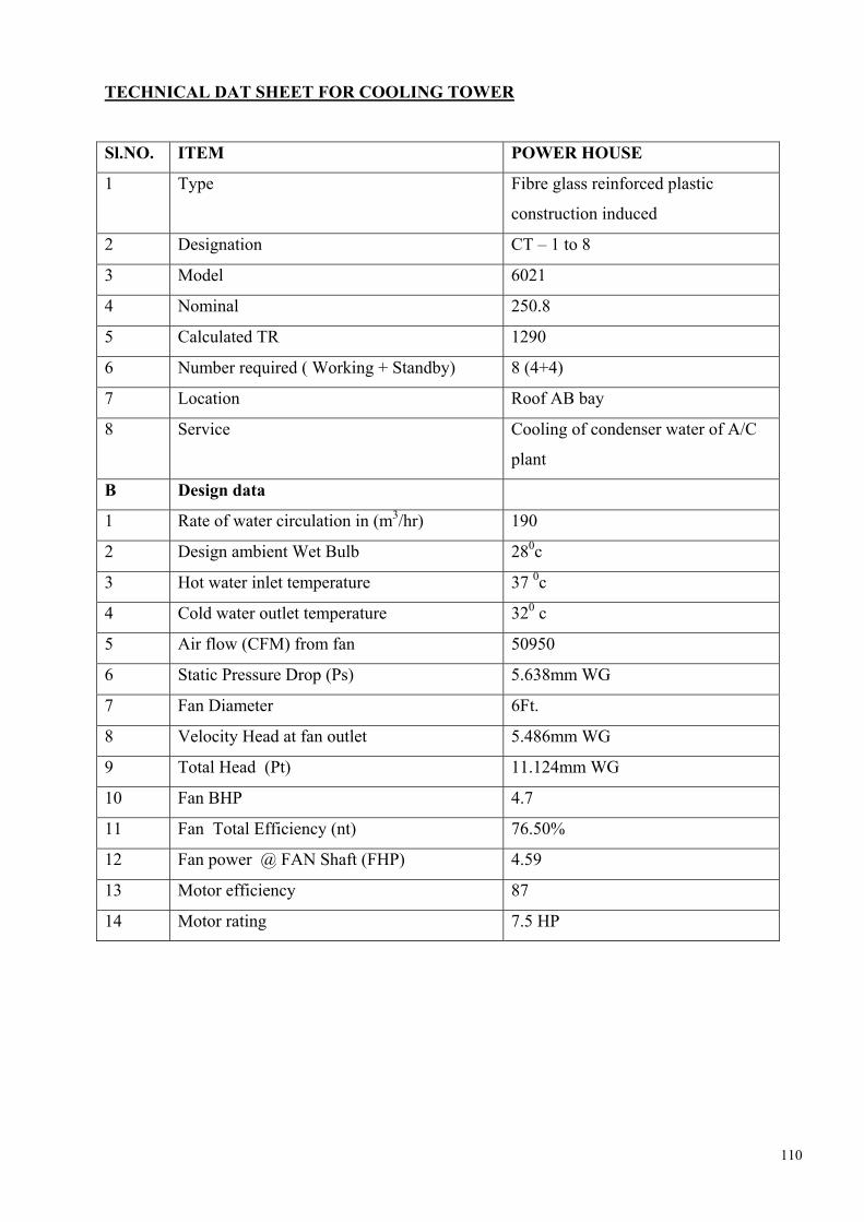
110
TECHNICAL DAT SHEET FOR COOLING TOWER
Sl.NO. ITEM POWER HOUSE
1 Type Fibre glass reinforced plastic
construction induced
2 Designation CT – 1 to 8
3 Model 6021
4 Nominal 250.8
5 Calculated TR 1290
6 Number required ( Working + Standby) 8 (4+4)
7 Location Roof AB bay
8 Service Cooling of condenser water of A/C
plant
B Design data
1 Rate of water circulation in (m3/hr) 190
2 Design ambient Wet Bulb 280c
3 Hot water inlet temperature 37 0c
4 Cold water outlet temperature 320 c
5 Air flow (CFM) from fan 50950
6 Static Pressure Drop (Ps) 5.638mm WG
7 Fan Diameter 6Ft.
8 Velocity Head at fan outlet 5.486mm WG
9 Total Head (Pt) 11.124mm WG
10 Fan BHP 4.7
11 Fan Total Efficiency (nt) 76.50%
12 Fan power @ FAN Shaft (FHP) 4.59
13 Motor efficiency 87
14 Motor rating 7.5 HP

111
C Material of Contruction
1 Casing F.R.P
2 Sum Tank F.R.P.
3 Fill PVC Light Grey colour
4 Louvers PVC Integral with fill
5 Nozzle Polypropylene Model – 68 – 3738-
04 2(0.621 inch)
6 Supporting Structure MS .Hot Deep Galvanised
7 Strainer 2 INCH MESH×0.080 woven wire
HDG
8 Ladder MS. Hot Deep Galvanised
9 Fan Blade Casting Aluminum Alloy
10 Fan casing F.R.P
11 Bird screen on top of Tower 5 / 16 Gauge HDG & welded steel
wire hops HDG
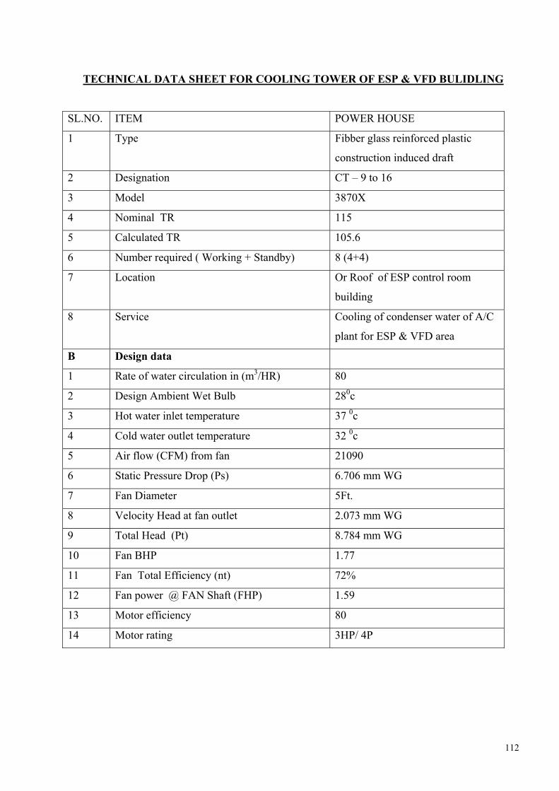
112
TECHNICAL DATA SHEET FOR COOLING TOWER OF ESP & VFD BULIDLING
SL.NO. ITEM POWER HOUSE
1 Type Fibber glass reinforced plastic
construction induced draft
2 Designation CT – 9 to 16
3 Model 3870X
4 Nominal TR 115
5 Calculated TR 105.6
6 Number required ( Working + Standby) 8 (4+4)
7 Location Or Roof of ESP control room
building
8 Service Cooling of condenser water of A/C
plant for ESP & VFD area
B Design data
1 Rate of water circulation in (m3/HR) 80
2 Design Ambient Wet Bulb 280c
3 Hot water inlet temperature 37 0c
4 Cold water outlet temperature 32 0c
5 Air flow (CFM) from fan 21090
6 Static Pressure Drop (Ps) 6.706 mm WG
7 Fan Diameter 5Ft.
8 Velocity Head at fan outlet 2.073 mm WG
9 Total Head (Pt) 8.784 mm WG
10 Fan BHP 1.77
11 Fan Total Efficiency (nt) 72%
12 Fan power @ FAN Shaft (FHP) 1.59
13 Motor efficiency 80
14 Motor rating 3HP/ 4P

113
C Material of construction
1 Casing F.R.P
2 Sump Tank F.R.P.
3 Fill PVC Light Grey colour
4 Louvers PVC Integral with fill
5 Nozzle Polypropylene
6 Supporting Structure MS .Hot Deep Galvanised
7 Strainer ½ “ X ½ “ MESH HDG
8 Ladder Portable Aluminum Ladder
9 Fan Blade Casting Aluminum Alloy
10 Fan casing F.R.P
Bird screen on top of Tower 5 / 16 Gauge HDG & welded steel
wire hops HDG

114
TECHNICAL DATA SHEET FOR CENTRIFIGUAL FAN FOR AHU
SL. No.
DESCRIPTION AHU 1 TO 12 AHU 13 TO 15 AHU 16 TO 18 AHU 19 TO 20 AHU 29 TO 36 AHU 21 TO 28
1 Manufacture ABB ABB ABB ABB ABB ABB 2 Model No. GFAB –5 - 125 GFAB –5 100 GFAB –5 –080 GFAB –5 – 125 GFAB–5 – 125 GFAB –5 – 080 3 Location Power House
Bidg Power House Bidg.
Power House Bidg.
Power House Bidg.
VFD Control room
ESP control room
4 Selected capacities ( CUM /HR)
55000 40000 24000 48000 50000 20000
5 Fan Total pressure
127.2 128.26 128.26 61.52 62.24 62.03
6 Impeller diameter (mm)
1120 900 710 1120 1120 710
7 Type of impeller
Backward curved Aerofoil Shape
8 Speed 820 1090 1380 610 640 1000 9 Fan total
efficiency 84% 82% 76% 82% 76% 82%
10 Bearing type Double row spherical roller/ Deep groove ball bearing 11 Recommended
motor KW 30 22 15 15 15 7.5
17 Motor speed (RPM)
20 Material a) Impeller
(Blade and shroud)
2.5 mm thk MS 2.5/ 2.0 mm thk MS
2.5 / 2.0mm thk MS
2.5 mm thk MS 2.5 mm thk MS 2.5 / 2.0mm thk MS
b) Impeller disk 2.5 mm thk MS 2.0mm thk MS 2.0 mm thk MS 2.5 mm thk MS 2.5 mm thk MS 2.0mm thk MS c) Casing 3mm thk MS 3mm thk MS 3mm thk MS 3mm thk MS 3mm thk MS 3mm thk MS ) Shaft 55 mm dia
EN8 48mm dia EN8 42mm dia EN8 55mm dia EN8 55mm dia EN8 mm dia EN842
21 GD2 of fan 94 kgm2 32.8 kgm2 15.6kgm2 94 kgm2 94 kgm2 15.6 kgm2 22 Quantity 12Nos. 3Nos. 3Nos. 2Nos. 8Nos. 8Nos.
Motors
SL. No.
DESCRIPTION AHU 1 TO 12 AHU 13 TO 15 AHU 16 TO 18 AHU 19 TO 20 AHU 29 TO 36 AHU 21 TO28
1 Model Kirloskar Electrical Co. LTD 2 Motor type NFLP Cage 3 Quantity 12 3 3 2 8 4 4 Voltage and
frequency 415 V / 50 Hz
Speed at rated Voltage and frequency
1475 1470 1450 1450 1450 1440
5 Full load current
50 38 27.6 27.6 27.6 14.4
6 Efficiency (100% load)
91.8 0.87 0.86 0.86 0.86 0.83
7 Type of duty S1 (Continuous) 8 Standard
continuos bearing at 50 °c ambient temp(KW)
30 22 15 15 15 7.5
9 Direction of Rotation as view for DE END
Bi – Directional
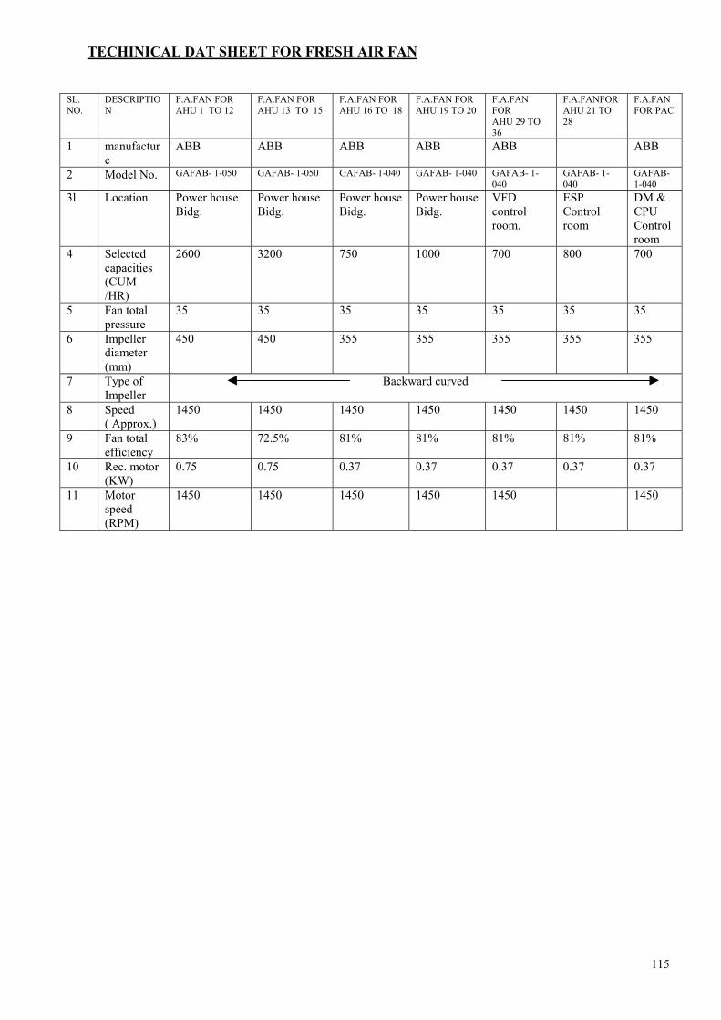
115
TECHINICAL DAT SHEET FOR FRESH AIR FAN
SL. NO.
DESCRIPTION
F.A.FAN FOR AHU 1 TO 12
F.A.FAN FOR AHU 13 TO 15
F.A.FAN FOR AHU 16 TO 18
F.A.FAN FOR AHU 19 TO 20
F.A.FAN FOR AHU 29 TO 36
F.A.FANFOR AHU 21 TO 28
F.A.FAN FOR PAC
1 manufacture
ABB ABB ABB ABB ABB ABB
2 Model No. GAFAB- 1-050 GAFAB- 1-050 GAFAB- 1-040 GAFAB- 1-040 GAFAB- 1-040
GAFAB- 1-040
GAFAB- 1-040
3l Location Power house Bidg.
Power house Bidg.
Power house Bidg.
Power house Bidg.
VFD control room.
ESP Control room
DM & CPU Control room
4 Selected capacities (CUM /HR)
2600 3200 750 1000 700 800 700
5 Fan total pressure
35 35 35 35 35 35 35
6 Impeller diameter (mm)
450 450 355 355 355 355 355
7 Type of Impeller
Backward curved
8 Speed ( Approx.)
1450 1450 1450 1450 1450 1450 1450
9 Fan total efficiency
83% 72.5% 81% 81% 81% 81% 81%
10 Rec. motor (KW)
0.75 0.75 0.37 0.37 0.37 0.37 0.37
11 Motor speed (RPM)
1450 1450 1450 1450 1450 1450

116
TECHINCAL DATA SHEET FOR AIR COOLED PACKAGED AIR CONDTIONER
OF DM & CPU CONTROL BUILDING
SL.NO. DESCRIPTINON TECHINICAL PARTICULARS
1.1 TYPE Air cooled packaged air conditioner
1.2 Make Blue Star limited 1.3 Model DPA 1803 1.4 For use in
DM & CPU building
1.5 Quantity ( working) 2Nos. 1.6 Quantity ( Standard by) 2 Nos. 1.7 Capacity (In TR) 15 TR (45000 K.cal/hr) 1.8 Power supply 380 – 420 V, 3ph ,50Hz 2 INDOOR UNIT 2.1 Depth 750 mm 2.2 Width 1500 mm 2.3 Height 1800 mm 2.4 Weight 513 KG. 2.5 No.of refrigerant circuit THREE 3 COOLING COIL –EVAPOURTOR 3.1 Make Blue star limited 3.2 Total coil face area 1.24 SQ.MTR 3.3 Rows deep 3 3.4 Fin spacing 10 FPI (Fins per inch ) 3.5 No. of circuit 27 3.6 Tube material Copper 3.7 Fin material Aluminium 4. EVAPOURAOR –AIR HANDLING UNIT 4.1 Size & quantity of blower 381 ×381 –1No. 4.2 Type of blower Centntrifugal forward curved
/ DIDW 4.23 Whether balanced statically and dynamically Yes 4.4 Total air quantity 6000 CFM (10,200 CMH) 4.5 Static pressure 35mm 4.6 Fan speed 978 rpm 4.7 Size and quantity of filter 457 × 933- 3Nos. 4.8 Type of filter Non oven polyster in HDPE
mesh 4.9 Motor type Totally enclosed foot
mounted 4.10 Motor KW & QTY 2.25kw /1 No. 4.11 Motor voltage characteristics 415 V-3PH- 50Hz

117
4.12 Motor insulation Class- F 4.13 Type of drive Belt drive 4.14 Condenser drain outlet 32 NB 5.1 COMPRESSORE 5.1 Compressor Copeland USA 5.2 Model CRN – 5- 0500 TFD 5.2 Qty. in each unit Three 5.4 Swept volume 17.74 cubic MTR/HR 5.5 Operation speed 2900 rpm 5.6 Type Hermetically sealed
reciprocating type 5.7 Refrigerant R – 22 5.8 Lubrication type Centrifugal forced feed 5.9 Oil charges (Ltitres) 1.95 5.10 Mounting arrangements 4 nos. rubber mounts with
metal sleeves 5.11 Weight of compressor 38.1 KG. 5.12 Compressor motor rating @ 45 0f Evap. temp.
@ 125 0F condensing temp. 4.9 KW
6 EXPNSION VALVE 6.1 Type Thermostatic expansion valve
with external equaliser line 6.2 Quantity for each 15 TR unit 3 Nos. 6.3 Make SPORLAN/ DANFOS/ALCO 8 AIR COOLED CONDENSER UNIT – OUT
DOOR
8.1 Unit 3 Nos. 8.2 Location Open space / shall be decided
at site 8.3 Overall size 1010 × 500 × 856 8.4 Weight 86.0kg – each 8.5 Coil face area 0.7032 Sq. MTR. 8.6 Rows deep Three 8.7 Fin spacing 12 FPI 8.8 Tube diameter 3 /8 “ OD (9.5mm) 8.9 Tube Pitch One inch. 8.1 Tube material Copper 8.11 Fin material Aluminium 8.12 No. of fan One for each condenser
(Total - 3 Nos. ) 8.13 Type of fan Propeller 8.14 Size of fan 600mm 8.15 Total air quantity 4000 CFM / 6800 CMH 8.16 Motor KW & qty. 0.5625 (For each condenser) 8.17 Motor type Totally enclosed / foot
mounted 8.18 Motor insulation Class –F 8.19 Type of drive Direct


119
DATA SHEET FOR DM PLANT & PT PLANT
STAGE II: DEMINERALISATION PLANT SL.NO. DESCRIPTION
01. DM Streams Nos. of stream 3 Flow through each stream M3 / hr 130
02. DM water storage tank Number 3 Capacity (each) M3 2000 Material of construction Epoxy coated MS tank
03. Degasser water pump Number 4 Capacity M3 / hr 150 Pressure Kg /cm2 4.5
04. Degasser blower Number Per stream 2 Capacity Nm3 /hr 2500 Static Head MMWC 150
05. Mixed bed blower Number 2 Capacity Nm3 /hr 314 Head MMWC 4000
06. DM Regeneration pump Number 2 Capacity M3 /hr 25 Head MWC 35
07. DM Make up pump Number 5 Capacity M3 /hr 100 Head MWC 110
08. Boiler fill pump Number 2 Capacity M3 /hr 150 Head MWC 150
09. Alkali dosing pump Number 2 Capacity LPH 1023 Head Kg/cm2 40
10. Alkali transfer pumps Number 2 Capacity M3 /hr 10 Head Kg/cm2 1.0
11. Effluent disposal pumps Number 3 Capacity M3 /hr 100 Head Kg/cm2 2.6

120
12. Acid unloading pumps Number 2 Capacity M3 / hr 20 Head Kg/cm2 1.0
13. Alkali unloading pumps Number 2 Capacity M3 / hr 20 Head Kg/cm2 1.0
BULK STORAGE TANKS For Acid For Alkali Number 4 2 Size dia and length MM 2750*8938 2750*8938 Capacity M3 50 50 Lining 4.5mm thick Rubber internally Concentration of chemical % 30-33% 48% Neutralising Pit Nos. 2 Capacity M3 200 DM Service Vessel Description ACF WAC SAC WBA SBA MB Flow rate M3/hr 130 130 130 130 130 130 Media filled AC CNP80WS S100 MP64 M500 S100H/M500 Resin height MM 1200 867 1150 867 1150 2*500 Qty of resin M3 10.572 3.270 3.770 3.270 3.770 2*1.635 Regenerant HCL Na OH HCL& Na OH

121
PRE TREATMENT PLANT SL.NO DESCRIPTION PT-DM PT-CW
01 Cascade Aerator 01 01 02. Reactor Clarifier
Number 01 03 Flow M3 /hr 350 3000 Effluent Turbidity NTU 10 10 Retention time at: Flocculation zone min 30 30 Clarifying zone min 90 90 Flow for flocculation zone M3 /hr 207 1400 Flow for clarifying zone M3 /hr 343 4405 O. D. at top m 14.2 38.5 Bridge revolving speed Min /rev 22
03. Gravity filter beds Number 03 03 Flow rate per filter M3 /hr 240 240 Surface flow rate (filtration rate) m3/ m2 /hr 5 5 Reservoir capacity M3 2*200 2*200
04. PTP Over head tank Size M 20*10*1.8 Volume M3 360
05. Clarified water storage tanks Size (one in two sections) M 21.5*10*4 Capacity M3 860
06. Filter backwash sumps Size M 130*10.3*2 Capacity M3 210
07. Sludge pit & Sump No of pits 2 Size M 12*12*3.5 Effective capacity M3 500
08. Filtered water transfer pumps Number 04 03 Capacity M3/hr 200 150 Head MWC 50
09. A/C vent make up pumps Number 3 Capacity M3 100 Head WMC 80
10. Clarified water make up pumps Number 3 Capacity M3 1800 Head WMC 20

122
SL.NO DESCRIPTION PT-DM PT-CW 11. CHEMICAL HOUSE
Alum solution preparation tanks (Common to DM & CW) Number 6 Size M 3.3*2.5 Capacity M3 27 Strength of alum solution % 10 Alum to be added Kg/tank 2700
12. Lime slaking tanks (Common to DM & CW) Number 4 Size M 4*3.5*2.5 Capacity M3 35 Strength of lime solution % 10 Lime to be added Kg/tank 3500
13. Lime solution preparation tanks (Common to DM, CW & AWEPT) Number 6 Size M 4.5*3.5*2.5 Capacity M3 39.37
14. Alum dosing pumps Number 2 4 Capacity LPH 300 2200 Pressure MWC 20 25
15. Lime slurry transfer pumps Number 2 Capacity LPH 150 Pressure MWC 15
16. Lime dosing pumps (Common to DM&CW) Number 3 Capacity LPH 360 Pressure MWC 30
17. Chlorination System Chlorinators 3 3 Capacity lb/day 50-3000 1000-10000 Type of injectors Variable throat type Water booster pump 3 3 Pump capacity M3/hr 10 40 Pressure MWC 19 36

123
ASH HANDLING SYSTEM
-: TECHNICAL DATA SHEETS : - BAHP, BALP, FLUSHING & SUMP JETTING WATER PUMPS
SL NO DESCRIPTION BAHP PUMP BALP PUMP
FLUSHING WATER PUMP
SUMP JETTING WATER PUMP
1 PUMPS
2 Manufacturer Kirloskar Brothers Limited
Kirloskar Brothers Limited
Kirloskar Brothers Limited
Kirloskar Brothers Limited
3
Model & type (Indicate whether axially split or End suctional)
8UPH5 Horizontal Split
case
UP250/30 Horizontal Split case
WF 35 - 35 End Suction
CPHM 80/40
End Suction
4 Numbers furnished 4 Nos. 10 Nos. 2 Nos. 2 Nos.
5 Numbers operating 2 Nos. 8 Nos. 1 No. 1 No.
6 Performance standard HIS HIS HIS HIS
7 Rated Capacity m3/ hr 600 615 1220 50
8
Total Dynamic Head at specified rated capacity (Meters of water column)
100 23 15 40
9 Required NPSH at rated duty point
5.2 3.8 3.7 1.6
10
Shut – off head,(Meters of water column) [ approx]
117 30 16 40.8
11
Pump efficency at rated capacity and head (Including IS tolerance)
84 % 89% 82% 49%

124
SL NO DESCRIPTION BAHP PUMP BALP PUMP
FLUSHING WATER PUMP
SUMP JETTING WATER PUMP
12
Pump input Power at specified rated capacity KW
194.52 43.28 60.78 11.12
13 Power required at pump shut – off , kw (approx)
158 28 56 8
14 Maximum pump input power in the range of operation
216 46 82 12
15 Rated output of the drive motor , kw.
260 60 75 15
16 Design temperature of water , (0C)
480C 480C 480C 480C
17 Pump rated Speed , rpm (approx) 1480 1470 970 1450
18
Win & Max operating point with in the range of operation
30 % to 120 % 30 % to 120 % 30 % to 120 %
50 % to 120 %
19
Specific speed (Indicate also the formula and units used) (approx)
70
- Nsp= 3.65 x N(RPH) x Q2(in
m3/sec) ------------------- H3/4 (in meter)
211 270 39
20 Type of pump sealing Self Sealing Self Sealing Self Sealing Self Sealing
21 Size of Suction flange, mm. 250 250 350 125
22 Size of discharge flange, mm. 200 250 350 80
23 Number of stage Single Single Single Single

125
SL NO DESCRIPTION BAHP PUMP BALP PUMP
FLUSHING WATER PUMP
SUMP JETTING WATER PUMP
24 Impeller size and type
Radial 560mm. (approx)
Radial 304
mm.(approx)
Wixed flow 420 mm. (approx)
Radial 344
mm.(approx)
25 Whether pump is suitable against reverse flow
No No No No
26 Max. Noise level DB 85 85 85 85
27
MATERIALS OF CONSTRUCTION (Mention IS or equivalent)
28 Casing (Specify BHN)
2 –2 .5 % NiCL IS 210 FG 260
(180 – 230 BHH)
2 –2 .5 % NiCL IS 210
FG 260 (180 – 230
BHH)
2 –2 .5 % NiCL IS 210
FG 260 (180 – 230
BHH)
2 –2 .5 % NiCL IS 210
FG 260 (180 – 230
BHH)
29 Impeller (Specify BHH)
Bronze LS 318 Gr. LTB2
Bronze IS 318 Gr. LTB2
Bronze IS 318 Gr. LTB2
Bronze IS 318 Gr. LTB2
30 Impeller wear ring (Specify BHH)
Not required Not required Not required Br. IS 318, Gr. LTB2
31 Casing wear ring (Specify BHH)
Bronze IS 318 Gr. LTB2
Bronze IS 318 Gr. LTB2 Not required Br. IS 318,
Gr. LTB2
32 Shaft Sleeve (Specify BHH)
SS AISI 410 (250 –280
BHH)
SS AISI 410 (250 –280
BHH)
SS AISI 410 (250 –280
BHH)
SS AISI 410 (250 –280
BHH)
33 Shaft Carbon Steel, IS 1570 40 C8
Carbon Steel, IS 1570 40 C8
Carbon Steel, IS 1570 40
C8
Carbon Steel, IS 1570 40 C8
34 Stuffing box / Gland 2-2.5% NICI 2-2.5% NICI
IS 210 FG 260
(180 –230 BHH)
IS 210 FG 260
(180 –230 BHH)
35 Gland packing Soft Asbestos
Greased & graphited
Soft Asbestos Greased & graphited
Soft Asbestos
Greased & graphited
Soft Asbestos Greased & graphited

126
SL NO DESCRIPTION BAHP PUMP BALP PUMP
FLUSHING WATER PUMP
SUMP JETTING WATER PUMP
36 Bolts, nuts, fasteners Carbon Steel Carbon Steel C40 IS 1570 C40 IS 1570
37 Base plate MS IS 226 UPTO 20mm
Thk & IS 2062 over 20
mm.thk
Thk & IS 2062 over 20
mm.thk
38 Pump Shaft Bearing
Antifriction Bearing
Antifriction Bearing
Antifriction Bearing
Antifriction Bearing
39 Number 2 Nos. per Pump
2 Nos. per Pump
3 Nos. per pump
1 Set per pump
40 Type & Manufacturer
6314
SKF OR Equv
6309
SKF OR Equv
6412/51314 & 6412
SKF OR
Equv
1 x SKF 3309 BG & 1 X NU
309 SKF OR Equv
41 Type of Lubricants Grease Grease Oil Grease
42 Arrangement of cooling Natural cooling Natural
cooling Natural cooling
Natural cooling
43 Design Life (Hrs) 25000 25000 25000 25,000
44 PUMP THRUST BEARING
45 Location DE &NDE DE &NDE DE DE
46 Type & Manufacturer SXF or Equiv. SXF or Equiv. SXF or
Equiv. SXF or Equiv.
47 Lubrication Grease Grease Oil Grease
48 Design of pump conforms to code/ Standard no.
IS 9137 IS 9137 IS 9137 DIN 24256 & ISO 2858
49 Characteristic curves for the pumps enclosed
Yes Yes Yes Yes
50 Coupling between motor shaft and pump shaft
Yes Yes Yes Yes
51 Manufacturer KBL Make KBL Make KBL Make Rati/Utkarsh
52 Type Flexible pin bush
Flexible pin bush
Flexible pin bush Spacer
53 Coupling guard furnished Yes Yes Yes Yes

127
SL NO DESCRIPTION BAHP PUMP BALP PUMP
FLUSHING WATER PUMP
SUMP JETTING WATER PUMP
54 Furnished air release valve , drain plugs etc.
Yes Yes Yes Yes
55
Total weight of pump – motor assembly , kg (approx)
5051 1115 2045 433
56
GD2 Valve of all rotating parts 1 kg/cm2) (Excluding motor)
107668 1172 68200 14240
57 Weight of the heaviest piece to be handled, kg.
Later Later Later Later
58
Various shop tests conform to the requirement of the specification
As per HIS As per HIS As per HIS As per HIS
59 Inspection & Testing
As per approved QAP
As per approved QAP
As per approved
QAP
As per approved
QAP

128
BOTTOM ASH SYSTEM
BOTTOM ASH HOPPER
♦ Type = W - Type water impounded having two sections ♦ Floor level = - 200 mm ♦ Top of the hopper = + 10.4545 mtr ♦ Height from the floor = + 10.6545 mtr ♦ Width (L-R) = 20.5 mtr (approx) ♦ Length(F-R) = 6.0 mtr (approx) ♦ Max. water level = +9845 mm ♦ Max ash level = + 9100 mm ♦ Hopper capacity at
♦ Max water lvl = 401 cu mtr ♦ Max ash level = 370 cu mtr
♦ Material of construction = MS 10 mm/SS 6 mm ♦ Refractory thickness = 230 mm ♦ Height of various locations in the hopper from floor lvl
W - point View
glasses (F/R)
bottom of seal trough
Normal Over flow level
Max water Over flow
level
Makeup connection Hopper top
Access door
+7132.5 +8200 +9394.5 +9695 +9845 + 9845(8500) +8300
SEAL TROUGH
♦ Material = SS 316 plate 6 mm ♦ Width of trough at
♦ Bottom = 254 mm ♦ Top = 368 mm
♦ Clearance with the seal plate ♦ Towards the hopper = ♦ Away from the hopper = ♦ From bottom of the hopper =
♦ Height of seal trough = 730 mm (F-R) / 730 mm (L-R) ♦ Over flow level = +8260 (4 nos , 2 each at front & rear) ♦ Makeup source = BALP & BAHP combined ♦ Flushing source = BAHP ♦ No of flushing nozzles = 18 ( ring header 150 NB) ♦ No of drain points = 6 (2 each in front & rear , one each in
LHS/RHS))

129
REFRACTORY COOLING TROUGH
♦ No of headers = 16 ( 6 EACH IN FRONT & RAER, 2 EACH IN L&R)
♦ No of supply lines = 16 ( 40 NB with orifice) ♦ No of drain lines = 20 ♦ Supply source = BALP 9(150 NB hdr) ♦ Flushing source = BAHP ♦ Over flow Drain to = Seal box
VIEW GLASSES
♦ Total no provided = 4 ( two at front , 2 at rear ) ♦ Cooling water source = BALP
OVER FLOW CONNECTIONS
♦ Nos provided = 4 ( two from each hopper) ♦ Location of OVER FLOW SEAL box = Rear side of the hopper ♦ Over flow connected to = Settling Bin
HOPPER MAKEUP
♦ Location = Front side of the hopper ( extreme L & R ) ♦ No of makeup connections = Two (one for each hopper) ♦ Source = BALP ♦ No of valves = One main iso valve 300 NB gate /300 NB Globe/ 200 NB ( 2 nos pneumatically operated) o Duration for complete filling = 20 - 30 Minutes ♦ Hopper over flow = Always to be continuous except during De-ashing in draw down mode /
HOPPER FLUSHING
Hopper slope nozzles flushing ( 18 nos per hopper) 3 nozzles are catered by one plug valve 100 NB
3+3 on each hopper = 6 plug valves Total 12 plug valves
BA hopper doors flushing ( 2 nozzles per door)
Total 4 plug valves
Emergency door flushing ( One nozzle per door)
Total 4 plug valves
Grinder dilution nozzles ( tapping after the HEWV)
Total 4 plug valves
Over flow weir box flushing 2 nos
• Location of the flushing valves = At Middle of the hoppers in floor level • Type of operation = Intermittent during deashing • Source = BAHP

130
OTHER CONNECTIONS
♦ Poking doors = 4 ♦ Hopper access doors = 2 (LHS/RHS)
BOTTOM ASH HOPPER GATE:-
♦ Nos provided = 4 ♦ Gate size = Square 914x914 mm ♦ Opening by = Air to water pressure at bottom of the power cylinder. ♦ Closing by = Air pressure at top of the power cylinder ♦ Flushing connections source = BAHP
HYDROPNEUMATIC TANK:
♦ Normal water level = Just above the centre line of the tank ♦ Source of makeup = SERVICE WATER/LP seal water pump discahrge ♦ Operating pressure = 5 - 7 ksc
CLINKER GRINDER DETAILS :-
♦ Type of grinder = EXEN single roll ♦ Capacity = 100 T/Hr ♦ Speed = 41 rpm ♦ Dia of roller = 318 mm ♦ Out put particle size = 25 mm or below ♦ Seal water requirement = 2 cu mtr/ grinder at 10 mtr WC ♦ DOR = CW For forward running ♦ Tip Height = 37 mm (approx) ♦ Wear tolerated =
HYDRO EJECTOR DETAILS :-
♦ Water source = BAHP (150 NB) ♦ Throat size = 100 MM ♦ Wear tolerable = 30- 40 MM ♦ HEWV type = Pneumatically operated ♦ Type of opening/closing = LIMIT SWITCH
DISCHARGE VALVE :-
♦ Nos provided = 4 ♦ Type of operation = Pneumatically , if required manually also can be Operated through the stud & hand wheel given at the top.
DISCHARGE LINE
♦ Pipe size = 250 NB (Basalt lining up to 6 mtr only)

131
TECHNICAL DATA SHEETS SLUDGE PUMPS
SLNO DESCRIPTION
1.01.00 Manufacturer SAM Turbo Industry Ltd.
1.02.00 Model and type ARS 80/290, Horisontal, Centrifugal end – suction single stage
1.03.01 Numbers furnished for 4 units 8 ( 2 nos. per unit)
1.03.02 Numbers operating 4 (1 no. Per unit)
1.04.00 Duty point capacity M3/Hr. 25
1.05.00 Type of Suction (Whether suction lift/flooded suction). Flooded
1.06.00
(a) Total dynamic head at specified capacity, MWC
(b) Total dynamic head at specified capacity, MLC
22 22
1.07.00 RATED SPEED, RPM 1460
1.08.00 Shut – off head, meters 24
1.09.00 Pump efficiency at rated capacity & head (with liquid of Sp. Gr. 1.0) 34%
1.10.00 Pump efficiency at rated capacity &head (with ash slurry of specific gravity 1.10 as being handled).
32%
1.11.00
Pump input Power at specified rated capacity KW.
(a) When handling clear water (b) When handling ash slurry (specific
gravity of Slurries considering 1.10)
4.40 5.15
1.12.00 Power required at pump shut-off KW 4.0
1.13.00 Rated output of the drive motor, KW (at 50 0C) 7.5
1.14.00 Design temperature of water/slurry, 0C. 500C
1.15.00 Pump Speed, rpm 1460 1.16.00 Specific speed
3.65 x RPH x √Q (m3 /sec.) NS = -- ------------------------------------------- H (m) 3/4
43.72 (approx)
1.17.00 Size of suction flange with counter flange, mm. 100 1.18.00 Size of discharge flange , with counter flange
,mm. 80
1.19.00 Impeller size and type 290 dia/closed 1.20.00 Number of vanes 3 1.21.00 Impeller tip speed, meters/min. 1330

132
SLNO DESCRIPTION 1.22.00 Noise Level 85 dB at 1 m distance 1.23.00 Materials of Construction (Mention IS or
equivalent)
1.23.01 Casing (Specify BHN) (i) Outer casing (ii) Inner casing (Metal Lining on volute)
C1 , IS-210,FG-260 Ni – hard type IV (550 BHN)
1.23.02 Impeller Ni – hard type IV 1.23.03 Wear plate (BS) Ni – hard type IV 1.23.04 Wear plate (SS) Ni – hard type IV 1.23.05 Shaft sleeve AISI – 410 , 400 BHN 1.23.06 Shaft EN -8 1.23.07 Stuffing Box. CI, IS-210, FG-260 1.24.00 Bolts, nuts, fasteners EN –8, BS 970 1.24.01 Base Plate MS Fabricated 1.25.00 Pump shaft bearing Steel 1.25.01 Number 2 Nos. 1.25.02 Type of lubrication Oil 1.25.03 Arrangement of cooling Oil sump 1.25.04 Type & Manufacturer Antifriction, ZKL/Eqv. 1.26.00 Pump Thrust bearing 1.26.01 Location NDE –1 No. 1.26.02 Type Antifriction 1.26.03 Lubrication Oil 1.27.00 Gland Sealing arrangement 1.27.01 External supply of water Yes 1.27.02 Quality of water Clear 1.27.03 Quantity, m3/hr. 1 m3/hr. 1.27.04 Pressure, kg/cm2 1.5 kg/cm2 (g) above pump
discharge pressure 1.28.00 Necessary Pressure gauge at each pump discharge
provided? Yes
1.29.00 Pump performance testing standard As per HIS 1.30.00 Design of pump conforms to Code /Standard No. IS - 5120 1.31.00 Coupling in direct drive arrangement provided? Yes 1.31.01 Manufacturer SAM 1.31.02 Type Pin Bush 1.31.03 Coupling guard furnished Yes 1.32.00 Furnished air release valves, draining plugs etc. Yes. 1.33.00 Pumps are designed to handle clinker of size, mm 10 mm 1.34.00 Total weight kg 1.34.01 Pump (bare pump) 290 kg. (approx) 1.34.02 Motor 120 kg. 1.34.03 Assembly, including base plate, Coupling etc. 1000 kg.(approx) 1.35.00 Various shop tests conform to requirement of the
specification. As per approved QAP of NTPC
1.35.01 Performance testing of pump possible in Manufacturer’s shop
Yes, Hyd. Tests pressure of outer casing 4.5 kg/cm2
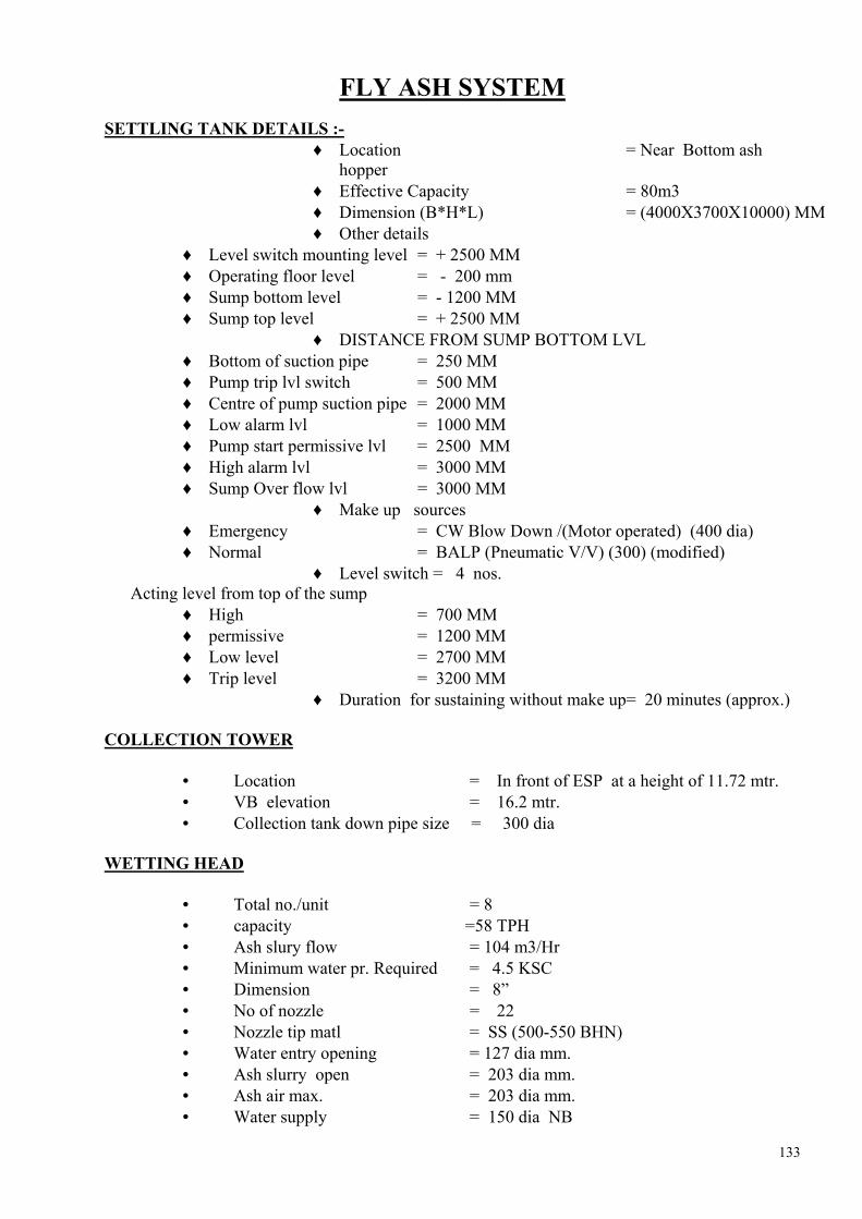
133
FLY ASH SYSTEM SETTLING TANK DETAILS :-
♦ Location = Near Bottom ash hopper
♦ Effective Capacity = 80m3 ♦ Dimension (B*H*L) = (4000X3700X10000) MM ♦ Other details
♦ Level switch mounting level = + 2500 MM ♦ Operating floor level = - 200 mm ♦ Sump bottom level = - 1200 MM ♦ Sump top level = + 2500 MM
♦ DISTANCE FROM SUMP BOTTOM LVL ♦ Bottom of suction pipe = 250 MM ♦ Pump trip lvl switch = 500 MM ♦ Centre of pump suction pipe = 2000 MM ♦ Low alarm lvl = 1000 MM ♦ Pump start permissive lvl = 2500 MM ♦ High alarm lvl = 3000 MM ♦ Sump Over flow lvl = 3000 MM
♦ Make up sources ♦ Emergency = CW Blow Down /(Motor operated) (400 dia) ♦ Normal = BALP (Pneumatic V/V) (300) (modified)
♦ Level switch = 4 nos. Acting level from top of the sump
♦ High = 700 MM ♦ permissive = 1200 MM ♦ Low level = 2700 MM ♦ Trip level = 3200 MM
♦ Duration for sustaining without make up= 20 minutes (approx.) COLLECTION TOWER
• Location = In front of ESP at a height of 11.72 mtr. • VB elevation = 16.2 mtr. • Collection tank down pipe size = 300 dia
WETTING HEAD
• Total no./unit = 8 • capacity =58 TPH • Ash slury flow = 104 m3/Hr • Minimum water pr. Required = 4.5 KSC • Dimension = 8” • No of nozzle = 22 • Nozzle tip matl = SS (500-550 BHN) • Water entry opening = 127 dia mm. • Ash slurry open = 203 dia mm. • Ash air max. = 203 dia mm. • Water supply = 150 dia NB
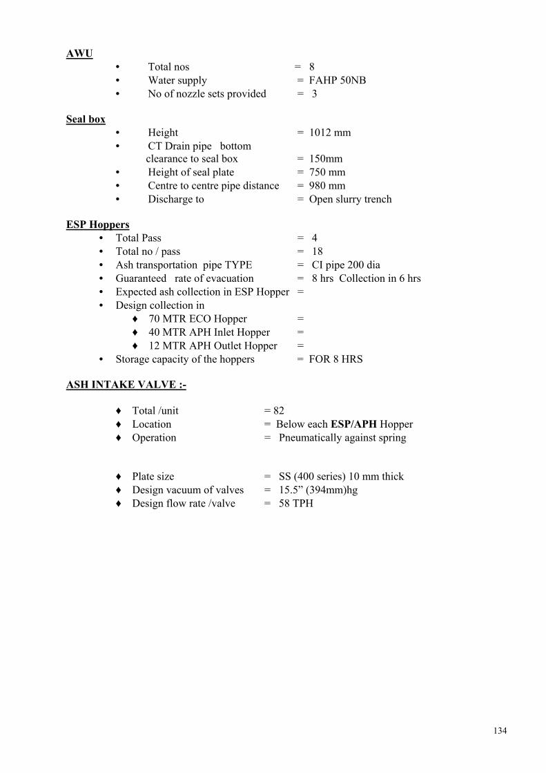
134
AWU
• Total nos = 8 • Water supply = FAHP 50NB • No of nozzle sets provided = 3
Seal box
• Height = 1012 mm • CT Drain pipe bottom
clearance to seal box = 150mm • Height of seal plate = 750 mm • Centre to centre pipe distance = 980 mm • Discharge to = Open slurry trench
ESP Hoppers
• Total Pass = 4 • Total no / pass = 18 • Ash transportation pipe TYPE = CI pipe 200 dia • Guaranteed rate of evacuation = 8 hrs Collection in 6 hrs • Expected ash collection in ESP Hopper = • Design collection in
♦ 70 MTR ECO Hopper = ♦ 40 MTR APH Inlet Hopper = ♦ 12 MTR APH Outlet Hopper =
• Storage capacity of the hoppers = FOR 8 HRS ASH INTAKE VALVE :-
♦ Total /unit = 82 ♦ Location = Below each ESP/APH Hopper ♦ Operation = Pneumatically against spring
♦ Plate size = SS (400 series) 10 mm thick ♦ Design vacuum of valves = 15.5” (394mm)hg ♦ Design flow rate /valve = 58 TPH

135
TECHNICAL DATA SHEETS : HP/ LP SEAL WATER PUMPS SLNO DESCRIPTION HP SEAL WATER
PUMP LP SEAL WATER
PUMP 1.00 PUMPS 1.01 Manufacturer MATHER & PLATT (I)
LIMITED MATHER & PLATT (I)
LIMITED 1.02 Model & type (Indicate
whether axially split or End suction)
RN – 50A Multistage
ET ISO 12 H END SUCTION
1.03 Numbers furnished 2 2 1.03 Numbers operating 1 1 1.04 Performance Standard HIS HIS 1.05 Rated capacity m3/hr 36 60 1.06 Total Dynamic Head at
specified rated capacity (Meters of water column)
135 55
1.07 Required NPSH at rated duty point
2.7m 3.0m
1.08 Shut- off head, (Meters of water column)[approx]
150 62
1.09 Pump efficiency at rated capacity and head (Including IS tolerance)
73% 72.5%
1.10 Pump input power at specified rated capacity KW.
18.13 12.39
1.11 Power required at pump shut- off, kw (approx)
2.8 9.0
1.12 Maximum pump input power in the range of operation
19.84 13.43
1.13 Rated output of the drive motor, KW
30 18.5
1.14 Design temperature of water, (0C)
UPTO 800C UPTO 800C
1.15 Pump rated Speed, rpm (approx)
2900 2900
1.16 Min & Max operating point with in the range of operation
Minimum = 30 % of rated flow
Maximum= 120 % of rated flow
Minimum = 30 % of rated flow
Maximum= 120 % of rated flow
1.17 Specific Speed (Indicate also the formula and units used) (approx)
1069.46 NS = N (rpm) x Q (GPH)
---------------------- [ H( ft )]3/4
957.24 NS = N (rpm) x Q (GPH)
---------------------- [ H( ft )]3/4
1.18 Type of Pump Sealing Self Water Self Water

136
1.19 Size of suction Flange, mm
65 80
1.20 Size of discharge flange , mm
50 50
1.21 Number of stages Four One 1.22 Impeller size and type 158 mm
(approx) Enclosed type
210 mm (approx)
Enclosed type 1.23 Whether Pump is suitable
against reverse flow Yes Yes
1.24
Max. Noise level dB
85 dB at a distance of 1.5
m above floor & 1 m horizontally from base of
pump.
85 dB at a distance of
1.5 m above floor & 1 m horizontally from base
of pump
1.25
MATERIALS OF CONSTRUCTION (Mention IS or equivalent)
1.25.01 Casing (Specify BHN) 2 –2. 5 % Ni CI to IS-210
FG 260 (240 –260 BHN)
2 –2. 5 % Ni CI to IS-210 FG 260
(240 –260 BHN)
1.25.02 Impeller (Specify BHN) Bronze IS 318 Gr. II (50 –70 BHN)
Bronze IS 318 Gr. II
(50 –70 BHN)
1.25.03 Impeller wear ring (Specify BHN) N.A. N.A.
1.25.04 Casing wear ring (Specify BHN)
Bronze IS Gr. II (50-70 BHN)
Bronze IS Gr. II (50-70 BHN)
1.25.05 Shaft Sleeve (Specify BHN) SS – 4 0 (400 BHN)
1.25.06 Shaft EN - 8 EN - 8
1.25.07 Stuffing box/Gland C1, IS –210, FG-260
1.25.08 Gland Packing Graphited Cotton
1.25.09 Bolts, nuts, fasteners MS MS
1.25.10 Base Plate IS- 2062/IS -226 IS- 2062/IS -226
1.26.00 PUMP SHAFT BEARING
1.26.01 Number N306 6306
1.26.02 Type & Manufacturer Antifriction ball bearing SKF/FAG /Eqv.
Antifriction ball bearing SKF/FAG /Eqv.
1.26.03 Type of Lubrication Grease Grease
1.26.04 Arrangement of Cooling Natural cooling Natural cooling
1.26.05 Design Life (Hrs.) 50,000 hrs 50,000 hrs

137
SLNO DESCRIPTION HP SEAL WATER PUMP
LP SEAL WATER PUMP
1.27.00 PUMP THRUST BEARING
1.27.01 Location Non driving end Non driving end
1.27.02 Type & Manufacturer SKF/PAG/Eqv. SKF/PAG/Eqv.
1.27.03 Lubrication Grease Grease
1.28.00 Design of pump conforms to code / Standard No.
IS - 5120 IS - 5120
1.29.00 Characteristic curves for the pumps enclosed YES Yes
1.30.00 Coupling between motor shaft and pump shaft
1.30.01 Manufacturer Mather & Platt/Unique Mather & Platt/Unique
1.30.02 Type Flexible pin & bush Flexible pin & bush
1.30.03 Coupling guard furnished Yes Yes
1.31.00 Furnished air release valve, drain plugs etc. Yes Yes.
1.32.00 Total weight of pump- motor assembly, kg (approx)
481 313
1.33.00 GD2 valve of all rotating Parts (kg – m2) (Excluding motor)
0.5 0.08
1.34.00 Weight of the heaviest piece to be handled, kg. (Approx)
254 185
1.35.00 Various shop tests conform to the requirement of the specification
Yes Yes

138
TECHNICAL DATA SHEETS:
SUMP PUMPS IN ASPH SLNO DESCRIPTION 01.00 Manufacturer Sam Turbo Industry Ltd. - Coimbatore
02.00 Model and Type V0+PS80C, Vertical Centrifugal non clog type redial split casing
03.00 Number furnished 2 Nos. 04.00 Rated Capacity, m3/hr. 80 05.00 Total bowl head at rated capacity, MWC N.A.
06.00 Total dynamic head at rated capacity , MWC 15
07.00 Shut - off head , MWC 21
08.00 Pump efficiency at rated capacity point with slurry (Sp.Gr. 1.18) 61%
09.00 Pump Speed rpm 1450(approx)
10.00 "Range of operation " within which the pump motor set can run continuously without any difficulty
50 % to 110 % of design capacity
11.00 Specific speed (indicate also the formula and units used)
3.65 x NRPM x Q (m3/Sec.) 103.5, Ns = -----------------------------
H(m)3/4
12.00 Size of discharge flange mm 80 13.00 Number of stages Single
14.00 Impeller size and type 242 mm (approx.), closed with wide open
15.00 Materials of Construction (Mention IS or equivalent)
15.01 Casing (Specify BHN) 2.7 % NI 1 % Cr, Alloy CI (350 BHN) 15.02 Impeller (Specify BHN) 2.7 % NI 1 % Cr, Alloy CI (350 BHN) 15.03 Impeller wear ring (Specify BHN) N.A. 15.04 Casing wear plate (Specify BHN) Alloy 15.05 Shaft sleeve (Specify BHN) AISI 304,400 BHN 15.06 Impeller Shaft SS,AISI 304 15.07 Motor shaft CS,EN-8,BS-970 15.08 Base Plate MS, IS-2062 15.09 Strainer MS, IS - 2062 15.10 Suspension pipe MS, ERW "C" Class (6mm thick) 15.11 Discharge pipe MS, ERW "C" Class ( 6mm thick)
15.12 Bolts Nuts, etc. AISI 316 for submerged portionEN8, BS 970 above water
15.13 Impeller Shaft bearing Carbon filled teflon 15.14 Gland Cast Iron IS- 210 FG -260 16.00 Pump shaft Bearing 16.01 Number 2 Nos. 16.02 Type of lubrication External clear water 17.00 Pump thrust bearing 17.01 Location Drive end. 17.02 Type Antifriction - ZKL Make 17.03 Lubrication Grease

139
17.04 Design life (Hrs.) 15000(approx) 18.00 Gland Sealing 18.01 Quality or external seal water Clear water 18.02 Quantity, M3.Hr. 2.5m3/he 18.03 Pressure, Kg/cm2(g) 3 kg/cm2 (g)
19.00 Design of pump conforms to Code/Standard IS - 9173
20.00 Pump input power at rated capacity KW (i) With clear water (ii) With slurry (sp.gr. 1.18)
5.36 KW 6.32 KW
21.00 Maximum pump input power at any point within "Range of operation " while handling specified liquid.
6.49 KW
22.00 Recommended motor rating 10 KW
23.00 Maximum permissive tip speed of Impeller at rated point 18.37 m/sec.
24.00 Whether pump is suitable for parallel operation Yes.
25.00 Minimum submergence required at design Capacity 350 mm
26.00 Discharge flange drilling standard pressure. ANSI ISO LBS RF
27.00 Minimum setting height required for pump operation in metre 1.70
28.00 Casing /column pipe test pressure Casing - 3.5 kg/cm2
29.00 GD2 value of rotating components of pump assembly in kg- m2. 0.290
30.00 Noise level , dB 85 dBA at 1.5 M distance above floor level & 1M horizontally from the base
of pump. 31.00 Performance test standard IS -5120
32.00 Pump input power at shut off head KW (sp.gr.1.0) 2
33.00 Total weight of assembly including drive motor discharge pipe base plate , etc, in kg .(approx)
900
34.00 Various shop tests conform to requirement of the specification As per NTPC approved QAP
35.00 Performance testing of pumps possible in manufacturer's shop Yes
36.00 Type of transmission Direct Pin - bush coupling.

140
DATA SHEET OF SEAL WATER PUMP Sl. No.
Description Company Description
1. Make : BEACON WEIR LTD, CHENNAI
2. Pump designation : Seal water pump.
3. Pump model. : FNB 4.
4. Pump type : Horizontal centrifugal.
5. Quantity : Two (2) 1 2 working + 1 standby ]
6. Liquid : Clarified water
7. Temperature : Ambient.
8. Flow (M3/hr) : 20
9. Differential head (MWC) : 80
10. Specific gravity (gm/cc) : 1
11. Impeller type : Closed
12. Casing type : Horizontal split.
13. No. of stages : 4
14. Direction of rotation : CCW from drive end.
15. Suction / discharge size (mm) : 76 / 76
16. Nozzle orientation : Side suction / top discharge.
17. Reference curve no. : 180247
18. Efficiency at duty (%) : 67
19. Rated speed (rpm) : 2900
20. Shut off head (m) : 112
21. Power absorbed at duty point (KW) : 6.5
22. Prime mover : AC electric motor.
23. Prime mover rating (KW) : 9.3
24. Guaranteed power consumption at
motor input terminal at rated
capacity and head (KW)
: Please refer Alstom Doc. No.
PND0001-AS-D-2036 for electrical
motor date sheet.

141
Sl. No.
Description Company Description
25. Type of lubrication : Grease.
26. Coupling type : Flexible pin & bush.
27. Coupling make /size : BWL/B5
28. Bearing type : Cylindrical Roller type.
29. Bearing make : SKF / Equiv.
30. Flange drilling standard : BS10TAB ‘J’
31. Bare pump weight (Kg) : 110 (approx.)
32. Casing : BS 1452 Gr. 220 -2% Ni.
33. Impeller : BS 1400 LG2
34. Casing wear ring : BS 1400 LB2
35. Shaft : BS 790 – 0S0 – M40
36. Sleeves : AISI 410
37. Stuffing box bush : BS 1452 Gr. 220
38. Base plate : MS fabricated.
39. Inspection and testing : As per approved QAP.

142
COOLING WATER PUMP Sl. No.
Description Company Description
1. Make : BEACON WEIR LTD, CHENNAI
2. Pump designation : Cooling water pump.
3. Pump model. : SDB 125/150
4. Pump type : Hrizontal centrifugal.
5. Quantity : Four (2) [ 1 working + 1 standby ]
6. Liquid : Clarified water
7. Temperature : Ambient.
8. Flow (M3/hr) : 150
9. Differential head (MWC) : 30
10. Specific gravity (gm/cc) : 1
11. Casing type : Horizontal split.
12. Impeller type : Closed
13. No. of stages : 1
14. Direction of rotation : CCW from drive end.
15. Suction / discharge size (mm) : 150 /125
16. Nozzle orientation : Side suction / side discharge.
17. Reference curve no. : 180083
18. NPSH required : 3.0 meter
19. Efficiency at duty (%) : 82
20. Rated speed (rpm) : 1450
21. Shut off head (m) : 32
22. Power absorbed at duty (KW) point : 14.95
23. Prime mover : AC electric motor.
24. Prime mover rating (KW) : 19
25. Guaranteed power consumption at
motor input terminal at rated
capacity and head (KW)
: Please refer Alstom Doc. No.
PND0001-AS-D-2036 for electrical
motor date sheet.

143
Sl. No.
Description Company Description
26. Type of lubrication : Grease.
27. Coupling type : Flexible pin & bush.
28. Coupling make /size : BWL/B5
29. Coupling weight : 8.7 kg (approx.)
30. Bearing type : Roller / ball / sleeve.
31. Bearing make : SKF / Equiv.
32. Flange drilling standard : BS4504 T16/11
33. Bare pump weight (Kg) : 182 (approx.)
34. Pump dynamic load : 319 kg (approx.)
35. Casing : IS 210 Gr. FG 260 2% NiCL.
36. Impeller : IS 318 LTB2
37. Casing wear ring : IS 318 LTB2
38. Shaft : AISIC 1040
39. Sleeves : AISI 410
40. Base plate : MS fabricated.
41. Inspection and testing : As per approved QAP.

144
FLY ASH WATER PUMP Sl. No.
Description Company Description
1. Make : BEACON WEIR LTD, CHENNAI
2. Pump designation : F.A. water pump.
3. Pump model : SDB 200/250.
4. Pump type : Horizontal centrifugal.
5. Quantity : Eight (8) [ 4 working + 4 standby ]
6. Liquid : Bottom ash hopper overflow water (TSS <100) containing abrasive ash particles.
7. Temperature : Ambient
8. Flow (M3/hr) : 644
9. Differential head (MWC) : 55
10. Specific gravity (gm/cc) : 1
11. Casing type : Horizontal split
12. Impeller type : Closed
13. No. of stages : 1
14. Direction of rotation : CCW from drive end.
15. Suction / discharge size (mm) : 250/200
16. Nozzle orientation : Side suction / side discharge.
17. Reference curves no. : 180080
18. NPSH required : 5.4 Meter
19. Efficiency at duty (%) : 89
20. Rated speed (rpm) : 1480
21. Shut off head (m) : 64
22. Power absorbed at duty (KW) : 108.4
23. Prime mover : AC electric motor
24. Prime over rating (KV) : 132
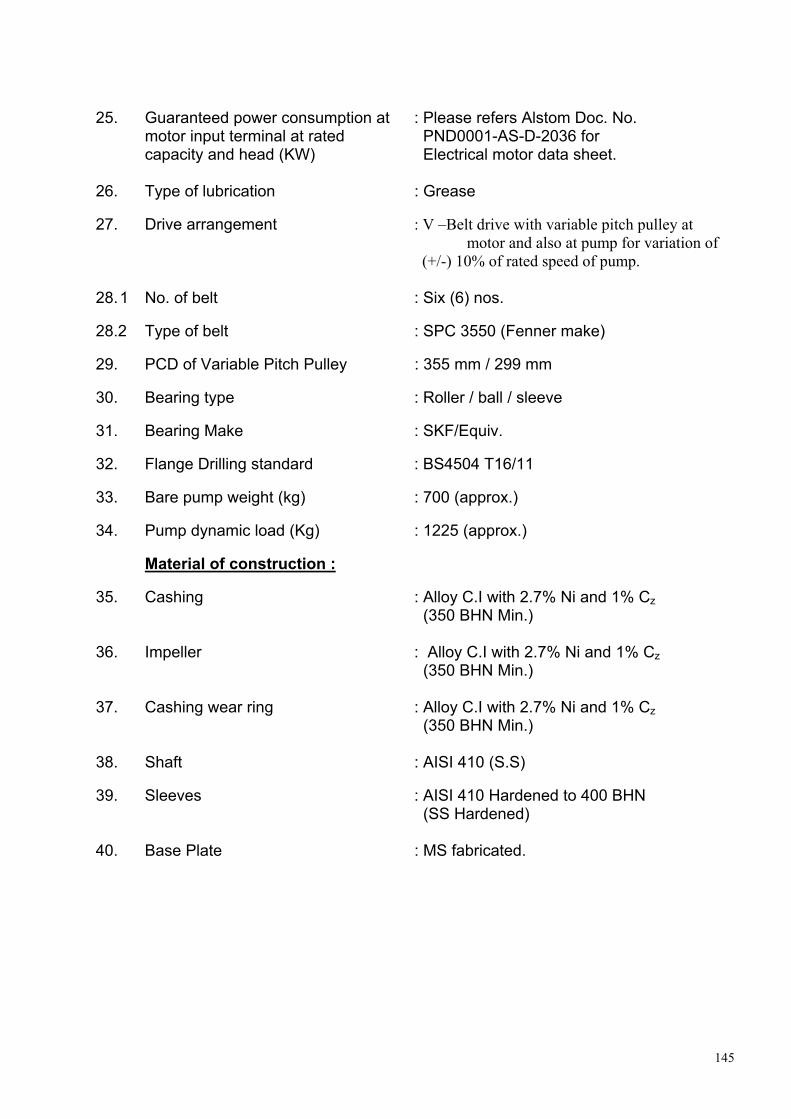
145
25. Guaranteed power consumption at
motor input terminal at rated capacity and head (KW)
: Please refers Alstom Doc. No. PND0001-AS-D-2036 for Electrical motor data sheet.
26. Type of lubrication : Grease
27. Drive arrangement : V –Belt drive with variable pitch pulley at motor and also at pump for variation of
(+/-) 10% of rated speed of pump.
28. 1 No. of belt : Six (6) nos.
28.2 Type of belt : SPC 3550 (Fenner make)
29. PCD of Variable Pitch Pulley : 355 mm / 299 mm
30. Bearing type : Roller / ball / sleeve
31. Bearing Make : SKF/Equiv.
32. Flange Drilling standard : BS4504 T16/11
33. Bare pump weight (kg) : 700 (approx.)
34. Pump dynamic load (Kg) : 1225 (approx.)
Material of construction :
35. Cashing : Alloy C.I with 2.7% Ni and 1% Cz (350 BHN Min.)
36. Impeller : Alloy C.I with 2.7% Ni and 1% Cz (350 BHN Min.)
37. Cashing wear ring : Alloy C.I with 2.7% Ni and 1% Cz (350 BHN Min.)
38. Shaft : AISI 410 (S.S)
39. Sleeves : AISI 410 Hardened to 400 BHN (SS Hardened)
40. Base Plate : MS fabricated.

146
COOLING / SEALING WATER PUMP Sl. No.
Description Company Description
1. Make : BEACON WEIR LTD, CHENNAI
2. Pump designation : Cooling/ Sealing water pump.
3. Pump model. : BWC 80/100 C.
4. Pump type : Horizontal centrifugal..
5. Quantity : Four (4) [ 2 working + 2 standby ]
6. Liquid : Clarified water
7. Temperature : Ambient.
8. Flow (M3/hr) : 80
9. Differential head (MWC) : 30
10. Specific gravity (gm/cc) : 1
11. Impeller type : Horizontal split.
12. Casing type : Closed
13. No. of stages : 1
14. Direction of rotation : CCW from drive end.
15. Suction / discharge size (mm) : 100 /80
16. Nozzle orientation : Side suction / side discharge.
17. Reference curve no. : 180086 / 01
18. NPSH required : 2.1 meter
19. Efficiency at duty (%) : 79
20. Rated speed (rpm) : 1450
21. Shut off head (m) : 33
22. Power absorbed at duty (KW) point : 8.27
23. Prime mover : AC electric motor.
24. Prime mover rating (KW) : 11

147
Sl. No.
Description Company Description
25. Type of lubrication : Grease.
26. Coupling type : Flexible pin & bush.
27. Coupling make /size : BWL/B5
28. Coupling weight : 8.7 kg (approx.)
29. Bearing type : Roller / ball / sleeve.
30. Bearing make : SKF / Equiv.
31. Flange drilling standard : BS4504 T16/11
32. Bare pump weight (Kg) : 141 (approx.)
33. Pump dynamic load : 247 kg (approx.)
34. Casing : IS 210 Gr. FG 260 2% NiCL.
35. Impeller : IS 318 LTB2
36. Casing wear ring : IS 318 LTB2
37. Shaft : AISIC 1040
38. Sleeves : AISI 410
39. Base plate : MS fabricated.

148
Technical data sheets for ESP Clause No
1.00.0 ELECTROSTATIC PRECIPITATOR 1.01.01 General i) Manufacture ALSTOM POWER ii) Manufacture’s model number 4FAA 9*45H-2*78-145.5-A iii) Dimensions (associated with one
boiler)
a) Width (across gas flow ) (mm) 80,200 b) Flange to flange length (in direction
of gas flow) (m) 65,030
c) Height between bottom of hoppers to support level (m)
9,290
d) Height between support level to top of monorail steel (m)
21,055 (Approx.)
e) Height between top insulator compartments to top of monorail steel (m)
5,200 (Approx)
iv) Number of electrical fields in series 9 v) Number of ESP casing per Boiler 4 Vi ) Number of gas streams per Boiler 4 vii) Maximum bus voltage (kV) 70 (at full load) viii) Average bus voltage (KV) 43 ix) Installed power per set of ESP of one
Steam (Generator kVA) 8108
x) Guaranteed power consumption per set of ESP ‘s of one steam generation at the guarantee point (kw)
Refer clause no .1.14.19
xi) Power consumption per set of ESP’s one steam generator at the guarantee point without intermittent charging
Not Applicable
xii) Guarantee collection efficiency (%) 99.97% at guarantee point (Design coal )
xii) Guarantee collection efficiency without intermittent charging (%)
Not Applicable
xiv) Guarantee pressure drop across ESP (mm wg)
17 at the guarantee point
Xv Guarantee air in leakage rate (m3/sec) per Boiler
7.77at the guarantee point

149
Xvi Specific collection area (m 2 /m3 /sec),
and the corresponding gas flow 315.19 at 777.75m3/s
Xvii Total active collection area( m2) per Boiler
245138.4
Xviii Treatment time (sec) and the corresponding gas flow
47.28 at 777.75m3/s.
Xix Gas velocity through ESP (m/sec) 0.857 at 777.75 m3/sec. Xx Aspect ratio 2.78 Xxi Effective migration velocity (m/sec) 0.02574 at Guarantee point. Xxii Proposed Standard for concluding
the performance tests Method of 17 EPA.
1.02.00 Predicted performance At 777.75 m3 /Sec. Gas flow rated at 125 deg.C temperature ( Guarantee point ) design coal.
1.03.02 With intermittent charging & indicating charge ratio of all the fields assumed.
At 777.75m3/sec at 125 Deg.C Guarantee point
i) Coal fired Design coal ii) Inlet dust concentration (gm/Nm3) 63.387
guarantee point iii) Outlet dust concentration (mg/Nm3) 20.00 Iv Collection efficiency with one field out
of service (%) 99.94
V Collection efficiency with two series fields out of field
99.88
Vi Collection efficiency with three series fields out of field out of service (%)
99.75
vii) Collection efficiency with four series fields out of service (%)
99.47
viii) Collection efficiency with five series fields out of service (%)
98.81
Ix) Collection efficiency with six series fields out of service (%)
97.12
x) Collection efficiency with seven series fields out of service (%)
90.00
xi) Collection efficiency with eight series fields out of service (%)
80.00
xii) Collection efficiency with all fields out of service (%)
40.00
xiii) Collection efficiency (with all fields working) of (%)
a) First field 80.00 b) Second field 15.00 c) Third field 3.00 d) Fourth field 0.80 e) Fifth field 0.50 f) Sixth field 0.30 f) Seventh field 0.20 g) Eighth field 0.13 h) Ninth field 0.04

150
xiv) Collection efficiency (with two
preceding fields out of service ) (%)
a) Second field (First field out of service)
60.00
b) Third field 55.00 c) Fourth field 10.00 d) Fifth field 2.00 e) Sixth field 1.00 f) Seventh field <1 g) Eighth field <1 h) Ninth field <1 xv) Gas temperature drop across ESP at
the guarantee point flow ,Deg.C 7
Xvi Max-available corona current per 100 m2 surface (milliamps)
30
xvii) Max-available corona power per 100 M2 surface (watts)
1811.00
1.04.00 Precipitator Casing i) Material Mild Steel ii) Plate thickness 6mm Iii) Design pressure (mmwg) +660 at 67% yield strength iv) Design temperature (deg C) 200.00 v) Max. temperature withstand capacity
and duration 300 for approx. 30 min
vi) Number of inspection doors per ESP 18.00 vii) Dimension of access opening of
inspection doors (mmXmm) 700X500
1.05.00 Gas Distribution system i) Method of ensuring uniform gas
distribution Perforated screens at inlet and spaced sheets at outlet
ii) Number of distribution plates /screens
2 in inlet &1 in outlet
iii) Material Mild Steel Iv) Thickness of distribution
plates/screen 2mm
v) Number of gas distribution screens in series
2+1
vi) Free area per gas screen 35,35 &20 percent vii) Dimension of openings in the screen Inlet- 85mm dia
outlet –120mm gap viii) Details of rapping gear for distribution
plates Tumbling Hammer

151
1.06.00 Discharged electrode i) Type Spiral, self tensioned ii) Material of electrode Stainless steel to grade
UH-904L iii) Material of frame Mild steel iv) Configuration Spiral round wire v) Diameter /thickness(mm) 2.7 vi) Height in contact with gas (m) 14.55 vii) Total effective length (m) 18.0 viii) No. of electrodes per gas stream 25,272 ix) Spacing of electrodes in th direction
of gas flow (mm) 225-150-150-225
x) Total effective electrode length (per boiler) m
602,528
xi) Total individual electrode frame height (m)
NA
xii) Total assembled electrode frame height (m)
14.25
xiii) Vertical distance between pipe frames (if used ) (mm)
4671
Xiv) Sized and weight of pipe frames (diameter and schedule )
a) Vertical frames Refer erection drawing b) Cross frame Refer erection drawing Xv Weight of an assemble frame
associated with single rapper (kg) 6993 kg, incl spirals(approx.)
xvi) Max. available corona current per linear metre of electrode (milliamps)
a) First field 0.15 b) Second field 0.15 c) Third field 0.15 d) Fourth field 0.15 e) Fifth field 0.15 f) Sixth field 0.15 g) Seventh field 0.15 h) Eighth field 0.15 i) Ninth field 0.15 xvii) Max. available corona power per
linear metre of electrode (watts)
a) First field 7.3 b) Second field 7.3 c) Third field 7.3 d) Fourth field 7.3 e) Fifth field 7.3 F) Sixth field 7.3 g) Seventh field 7.3 h) Eighth field 7.3 i) Ninth field 7.3

152
1.07.00 Collecting Electrodes i) Material Ms rolled sheet ii) Sized of electrodes (mm) a) Width 750 b) Height 14550 c) Thickness 1.25 iii) Effective height & width in contact
with gas (m) 14.55 & 0.75
iv) Number of gas passages per gas stream
52
v) Spacing of gas passages(mm) 300.0 vi) Total effective cross–sectional area
per gas stream (m2) 227.00
vii) Number of collecting electrodes per gas stream
2862
viii) Effective collection surface area per electrode (m2)
21.83
Ix ) Total effective collection area (m2) (per boiler)
245,138
x) Distance between adjacent fields measured from the end of collecting plate rows of one field to the beginning of the collecting plate rows of the next field (m)
1.735
xi) Method of interconnection of plates Huck Bolted to Shock Bar xii) Method of suspension Hook &slot xiii) Weight of collection surface
associated with a single rapper (kg) 785 (Approx) (per hammer)
xiv) Available corona current per square metre of effective collecting surface (mA/m2)
a) First field 0.03 b) Second field 0.30 c) Third field 0.30 d) Fourth field 0.30 e) Fifth field 0.30 f) Sixth field 0.30 g) Seventh field 0.30 h) Eighth field 0.30 i) Ninth field 0.30 xv) Max. available corona power per
square metre of effective collecting surface (watts/m2)
18.1
xvi) Surface finish of the collecting electrode
Smooth
xvii) Maximum roughness --- xvii) Reference drawing NO. PND0001-EP-M-0007

153
1.08.00 Electrode rapping Equipment 1.08.01 Discharge Electrodes i) Type Tumbling Hammer ii) Number of rapping gear shafts per
gas stream (per ESP) 36
iii) Location of drive ( top/side) Top on roof of ESP iv) Number of hammers per shaft 13 v) Location of rapping points At 1/3& 2/3 of emitting frame
height vi) Weight of single hammer (kg) 3 vii) Available range of rapping electrodes
(Kg-m) Min 250 g on emitting frame
viii) Maximum effective electrodes length and its percentage raped at any time (m,%)
151,632m,0.64%
ix) Rapper controller a) Type Microprocessor based b) Method of frequency control Adjustable c) Method of intensity control N/A x) Nominal time interval between raps
(minute)
a) First field 6 b) Second field 6 c) Third field 6 d) Fourth field 6 e) Fifth field 6 f) Sixth field 6 g) Seventh field 6 h) Eighth field 6 i) Ninth field 6 xi) Available range of rapping time
interval (minute)
a) First field 0-1440 b) Second field 0-1440 c) Third field 0-1440 d) Fourth field 0-1440 e) Fifth field 0-1440 f) Sixth field 0-1440 g) Seventh field 0-1440 h) Eighth field 0-1440 i) Ninth field 0-1440 xiii) Accessibility / Location ESP Control Room xiv) Drawing ref. No Refer ESP write-up in
Section, Subsection-A xii) Time of single rapping cycle Variable, but standard is

154
1.08.02 Collecting Electrodes i) Type Tumbling Hammer ii) Number of rapping gear shafts per
gas stream (per ESP) 18
iii) Number of hammers per shaft 26 and 27 iv) Weight of single hammer (kg) 5 v) Number of plates rapped per rapper 6 vi) Rapping energy available on
collecting surface (kg-m) 2.2
vii) Available range of rapping energy on collecting surface (kg-m)
constant
viii) Maximum collecting surface area rapped at any instant (m2)
130.95
ix) Rapper controller a) Type Microprocessor based b) Method of frequency control Adjustable c) Method of intensity control N.A x) Specific rapping energy (i.e rapping
energy/plate weight) 2.2X10 -3kg m/kg
xi) Rapping acceleration nominal to plate
a) minimum (g) 140 b) maximum (g) 1000 xii) Normal time interval between raping
(minutes)
a) First field 6 b) Second field 10 c) Third field 15 d) Fourth field 24 e) Fifth field 40 f) Sixth field 60 g) Seventh field 90 h) Eighth field 130 i) Ninth field 180 xiii) Available maximum range of rapping
time interval (minute) (between two successive raps on the same electrode )
a) First field 0-1440 b) Second field 0-1440 c) Third field 0-1440 d) Fourth field 0-1440 e) Fifth field 0-1440 f) Sixth field 0-1440 g) Seventh field 0-1440 h) Eighth field 0-1440 i) Ninth field 0-1440 xiv) Accessibility/ location ESP control room Xv Time of single rapping cycle Variable, but standard is on
minute

155
1.09.01 Insulators System i) Type Support Shaft ii) Material Porcelain Porcelain iii) Creepage distance 355mm 700mm iv) Number of insulators
per T/R set 4 1
v) No of insulator chamber per T/R set
- -
vi) Impulse flashover voltage (Kv), Peak (1.2/50 microsec. Wave)
170 170
1.10.00 Ventilation system (per ESP) i) Total pressuring air requirement
(m3/hr) 5000
ii) Pressuring air per compartment (m3/hr)
Support Insulator =40 Shaft Insulator =80
iii) Number of fans normally operating 1 per ESP iv) Number of spare fans 1 per ESP v) Fan capacity (m3/hr) 5000 vi) Fan speed (rpm) 5.5 vii) Fan motor rating (KW) 15.0 viii) Manufacture and type of fan Backward curved blade ix) Duct heater capacity at normal
operation (KW) per ESP 90
x) Spare duct heater capacity (kw) xi) Total number of duct heaters 90 xii) Manufacture and type of duct heaters Escort / Kantilal Chunila /
Racold / Eqv xiii) Temperature of air to insulator
compartments (deg.c) 100
xiv) Number of insulator heaters 90 per ESP xv) Capacity of each heater (Kw) 1 KW xvi) Total insulator heater capacity (kw)
per ESP 90
1.11.00 Transformer Rectifier sets 1.11.01 General I. Type Thyristor II. Manufacture ADOR III. Rating (KVA) 81.00 IV. Number per field per gas sream 1 per series field V. Number bus sections per field per
gas stream 2
VI. Method of cooling and type of cooling liquid
ONAN/Silicon Oil
VII. Average amperes per set (mA) (secondary)
1130
VIII. Peak voltage available (KV) (D.C) 70 IX. Expected power required per stream
(kw) Varies depending on field condition
X. Location ESP roof XI. Mounting type Wheel mounted XII. Handling Equipment (yes/No) Yes

156
1.11.02 Transformer i) Type ONAN ii) Rating of each set a) input power (KVA) ---- b) input voltage (kv) 0.415 c) Output power (kw) 81 KVA d) Output voltage (KV) 70 (peak) e) Output current (A) 1.13 (mean) f) Number of primary taps supplied N.A g) Tap voltage (volts) N.A iii) Transformation ratio ----- iv) Class of insulation A v) Class of bushings Porcelain Bushing vi) Temperature rise over ambient
(deg.c)
winding 40 oil 40 1.11.03 Rectifiers i) Type Silicon Avlanche ii) Rating (kw) Refer Document No.
PND0001- EP-D-0938 iii) Number per T/R set 1 iv) Half wave / full wave rectification Full wave v) Rated current output of each rectifier
set (mA) 1130 (mean)
vi) Rated voltage output of each rectifier set (KV)
70
vii) Expected operating current (mA) 1130 (mean) viii) Expected operating voltage (KV) 43 (mean)

157
1.11.04 Automatic voltage control
Equipment
i) Manufacture Alstom power ii) Number of control cabinets per gas
stream 18
iii) Rating of each unit (KVA) a) First field 81.00 b) second field 81.00 c) third field 81.00 d) Fourth field 81.00 e) Fifth field 81.00 f) Sixth field 81.00 g) Seventh field 81.00 h) Eighth field 81.00 i) Ninth field 81.00 iv) Type of current limiting device Microprocessor based
control v) Type of voltage control device Microprocessor based
control vi) Duration of arc suppression Adjustable vii) Type of protection IP 54 (Installed Inside TP
control cabinet) viii) Ventilation Natural Ventilation ix) Cabinet dimensions 75 (W) X200(D)X290(H) x) Design ambient temperature 50 Deg.C xi) Power supply 24 V AC, 50Hz Single phase xii) Earthing and shielding Provided

158
1.12.00 Dust hoppers i) No. per field per stream 2 ii) No. per ESP of one boiler 72 (Total for oe Boiler ) iii) Material Mild steel iv) Plate thickness (mm) 6 mm v) Side angle (degrees) 60-80 vi) Valley angle (angle) 60 vii) Storage capacity of each hopper
(hour) 8hrs +10%
viii) Volumetric storage capacity of each hopper (m3)
187.41
ix) No. and height of gas screens per hopper
2 / 3.0m
x) No. of access doors per hopper One xi) Access door dimension (mmXmm) ApproxX500X600mm xii) Size of the hopper outlet flange
(mmXmm) 450X450
xiv) Hopper heating a) control temperature (deg C) 140 b) Hopper heating power per hopper
(KW) 15 (Max)
c) Hopper heating power per m2 (KW)
0.5 for bottom !/3 portion
xv) Hopper heater data a) Name of the manufacture Heat Tracel / Thermon / Hotf.
/ Eqv. b) voltage level 415V c) Maximum Watt density (W/Sq.M) 3w per square Inch d) Estimated life of heating module 25 years ( Approx.) e) Maximum exposure temp. rating of
the module 350-400 Deg.C
i) Moisture resistance a) prior to operation Good ii) after 2years of operation Good
xvi) Hopper dust level detectors a) Number per hopper 2 b) Type Radio Frequency
xvii) Ash collection rate per ESP (kg/hr) At 777.75m3/sec gas flow rate corresponding to the
guarantee point. a) first row 97400 b) second row 18250 c) Third row 3650 d) Fourth row 975 e) Fifth row 610 f) Sixth row 370 g) Seventh row 245 h) Eighth row 160 i) Ninth row 50

159
1.13.00 ESP Management system 1.13.01 T/R set Controllers
i) Processor designation & total Nos. 72.nos. per Boiler ii) max. charge ratio that EPROM can
obtain 1:999
iii) Feed back signal for charge ratio optimisation
-Spark rate (yes/No) Not Applicable -Opacity monitor (yes/No) Yes
iv) Off cycle charging current (mA) Provided v) Loop amplification 1-99% vi) First ignition angle after spark Adjustable vii) Maxm. Current per half period semi-
pulse mode Adjustable
viii) Self diagnostic feature (yes/No.) Yes ix) All the microprocessor based system/
subsystem supplied by bidder is designed to avoid y2K bug
Yes
x) The system as a whole shall comply British standard Disc PD-2000 regarding Y2k
Yes
1.13.02 Rapper Controller i) Nos.of controller for ESP of one
steam generator Including in TR Set control
ii) Communication facility with TR set controller and vice versa through common controller (yes/No)
Yes
iii) Selection of pre–programed rapping cycle frequency (Manual/ automatic/both)
Yes
1.14.00 Dust Emission Monitor 1.14.01 Manufacture’s name Erwin Sick 1.14.02 Model & Name and Number Varies according to the ma 1.14.03 Type Transceiver &Reflector 1.14.04 Quantity per Boiler 4 1.14.05 Range 0-200mg/Nm3 1.14.06 Calibrated accuracy Refer Document No
PND0001-EP-D-0801 1.14.07 Power Supply 240V AC 1.14.08 Automatic zero/Span adjustment with
manual override provided Yes
1.14.09 All accessories required for completeness of the system as per specification
Yes
1.14.10 Automatic compensation for variation in line voltage , detector sensitivity, lamp ageing, ambient illumination provided
Yes
1.14.11 Automatic shutter operation during purge air/power supply failure is provided
Yes
1.14.12 Alignment indicator provided Yes

160
1.14.13 Converter a) opacity indicator with selection of
measurement ranges provided Yes
b) output signal and number of outputs
4-20mA DC
c) Remote calibration control provided
Yes
d) Status indication provided Yes e) Number of alarms Two f) Provision for alarm with adjustable
time delay Yes
1.14.15 Power consumption (kw) for all gas stream connected to one boiler
Normal
i) T/R sets ,kw 245 ii) Collecting electrode rappers 6 iii) Discharge electrode rapppers iv) Insulation heater (Support &shaft) 216 v) Insulator fans 15 vi) Hopper heaters 540 vii) Any other load (Hot Air purging
,motor for opacity monitor Other Instruments Controls)
369
viii) Total 1391.00 1.15.00 Insulation &Cladding
i) Area to be insulated per four gas streams of precipitators (m2)
a) casing b) Hopper c) Roof d) Nozzles e) Any other f) Total 24415.00
ii) Material Lightly Resin bonded mineral wool
iii) Insulating material standard IS:8183 iv) Thickness (mm) 70 v) Density (kg/m3) 100.00 vi) Thermal conductivity (Kcal/deg.C) at
mean temperature of
a) 50 deg.C 0.0278 b)100 deg.c 0.0344 c) 150 deg.C 0.0392 d) 200 deg.C 0.0439 e) 250 deg.C 0.0483 f) 300 deg.C 0.0533 g) 350 deg.C h) 400 deg.C
vii) Resistive to micro-organism Yes viii) Incombustibility Yes Ix) Material of skin casing Aluminium x) Thickness of skin casing 16SWG

161
1.15.00 Equipment Weight (Total MT,Approx) i) Structural Steel 814.00 ii) Precipitator casing including gas
distribution system 1830.00
iii) Hoppers empty 938.00 iv) Hopper (full) - v) Collecting electrodes 1518.00 vi) Discharge electrodes 32.00 vii) Rapping system for collecting
electrodes 95.00
viii) Rapping system for collecting electrodes
96.00
ix) Insulators &insulator compartments 9.00 x) Platforms. Walkways, Stairs ways 280.00 xi) T/R sets 125.00 xii) Insulation and cladding 360.00 xiv) Others 1103.00 xv) Total estimated weight (per boiler)
(Tonnes).Approx. 7200 (Approx)

162
Description of the STAGE-II system-CHP2 (Unit-III & IV )
Coal is brought to Track Hopper-II of CHP from LINGARAJ Mines through our MGR system. Coal is unloaded in the track hopper-II by bottom open doors mechanism of wagons. Coal is fed to conveyors 13A or 13B by four Paddle Feeders (PF-1,2,3 & 4). PF-1,2 feed coal to conveyor 13A & PF-3,4 feed coal to conveyor13B.Two inline Magnetic Separators ILMS-1 & ILMS-2 are there on drive ends of conveors-13A & 13B respectively to separate magnetic material from the coal. Two suspended magnets SM-1 & SM-2 are there near pent house of track hopper to separate magnetic materials from conv.13A & 13B. Two nos of Metal Detector (MD-1 & MD-2) & Belt Weighers (BW1 & BW2)are there on conveyors 13A & 13B respectively. At Crusher house-II Conveyor 13A feed coal to VGFs-1,2 & CRUSHERS-1,2 & finally crushed coal of -20mm size to Belt Feeders-1,2. Conveyor 13B feed coal to VGFs-3,4 & CRUSHERS-3,4 & finally crushed coal of -20mm size to Belt Feeders-3,4. Belt Feeders-1,2 or Belt Feeders-3,4 feed crushed coal to conveyors 14A/14B or 20A/20B depending upon the requirement of Direct bunkering or stacking respectively. Incase of direct bunkering: Conveyors 14A, 14B transport coal up to TP15 & discharge the coal to conveyors 15A, 15B. Conveyors 15A, 15B transport the coal upto TP16 & discharge the coal to conveyors 16A,16B. Two inline magnetic separators (ILMS-3 & ILMS-4) are there on conveyors 15A & 15B respectively at TP16. Conveyors 16A, 16B transport coal upto TP18. At TP17 they discharge coal to bunker conveyor 18A. & at TP18 they discharge coal to conveyor 18B or 17A/17B. Conveyors 17A/17B transport coal upto TP20. At TP19 they discharge coal to conveyor 19A & at TP20 they discharge coal to conveyor 19B or 26A . In case of stacking: Belt Feeders-1,2 discharge coal to conveyor 20A & Belt Feeders-3,4 discharge coal to 20B at Crusher House-II. Conveyors 20A/20B discharge coal to Conveyor 21 at TP13. Conveyor 21 discharge coal to Boom conveyor of SR-3. In case of Reclaiming Bucket Wheels of SR-3 discharge coal to Boom conveyor of Stacker Reclaimer-3. Boom conveyors of SR-3 discharge coal to conveyors 21. Conveyor 21 discharge coal to 22A/22B at TP14. Conveyors 22A/22B discharge coal to conveyors 15A/15B at TP15. After TP15 path of reclaimed coal is same as incase of direct bunkering.
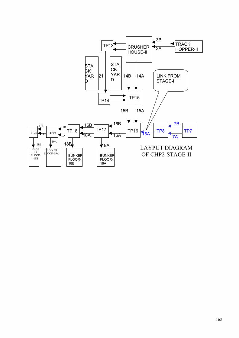
163
TRACK HOPPER-II CRUSHER
HOUSE-II TP13
TP15
TP16TP17TP18
BUNKER FLOOR-18B
BUNKER FLOOR-18A
13B
13A
14A14B
15A15B
16B
16A
16B
16A
18A18B
21
TP14
STACK YARD
STACK YARD
16A
7B
7A TP8 TP7
LINK FROM STAGE-I
TP19 TP20
19A 19B
BUNKER
FLOOR-19B
BUNKER FLOOR-19A
LAYPUT DIAGRAM OF CHP2-STAGE-II
17B 17B
17A 17A

164
Description of the STAGE-II system-CHP3 (Unit-V & VI )
Coal is brought to Track Hopper-III of CHP from LINGARAJ Mines through our MGR system. Coal is unloaded in the track hopper-III by bottom open doors mechanism of wagons. Coal is fed to conveyors 23A or 23B by four Paddle Feeders (PF-5,6,7 & 8). PF-5,6 feed coal to conveyor 23A & PF-7,8 feed coal to conveyor 23B. Two inline Magnetic Separators ILMS-5 & ILMS-6 are there on drive ends of conveors-23A & 23B respectively to separate magnetic material from the coal. Two suspended magnets SM-3 & SM-4 are there near pent house of track hopper to separate magnetic materials from conv.23A & 23B. Two nos of Metal Detector(MD-3 & MD-4) & Belt Weighers (BW3 & BW4)are there on conveyors 23A & 23B respectively. At Crusher house-III Conveyor 23A feed coal to VGFS-5,6 & CRUSHERS-5,6 & finally crushed coal of -20mm size to Belt Feeders-5,6. Conveyor 23B feed coal to VGFS-7,8 & CRUSHERS-7,8 & finally crushed coal of -20mm size to Belt Feeders-7,8. Belt Feeders-5,6 or Belt Feeders-7,8 feed crushed coal to conveyors 24A/24B or 30A/30B depending upon the requirement of Direct bunkering or stacking respectively. Incase of direct bunkering: Conveyors 24A,24B transport coal upto TP23 & discharge the coal to conveyors 25A,25B.Conveyors 25A,25B transport the coal upto TP24 & discharge the coal to conveyors 26A,26B. Two inline magnetic separators (ILMS-7 & ILMS-8) are there on conveyors 25A & 25B respectively at TP24. Conveyors 26A,26B transport coal upto TP26. At TP25 they discharge coal to bunker conveyor 28A. & at TP26 they discharge coal to conveyor 28B or 27A/27B. Conveyors 27A/27B transport coal upto TP28. At TP27 they discharge coal to conveyor 29A & at TP28 they discharge coal to conveyor 29B . In case of stacking: Belt Feeders-5,6 discharge coal to conveyor 30A & Belt Feeders-7,8 discharge coal to 30B at Crusher House-III. Conveyors 30A/30B discharge coal to Conveyor31 at TP21. Conveyor 31 discharge coal to Boom conveyor of SR-4 . In case of Reclaiming Bucket Wheels of SR-4 discharge coal to Boom conveyor of Stacker Reclaimer-4. Boom conveyors of SR-4 discharge coal to conveyors 31. Conveyor 31 discharge coal to 32A/32B at TP22. Conveyors 32A/32B discharge coal to conveyors 25A/25B at TP23. After TP23 path of reclaimed coal is same as incase of direct bunkering.

165
THERE ARE FOUR LINKS BETWEEN STAGE-I CHP, CHP2 OF STAGE-II & CHP3 OF STAGE-II. THEY ARE :
1. Link between stage-I CHP & CHP2 of stage-II at TP8. We can feed coal to Conveyor-16A of CHP2 from Conv.7A or 7B of stage-I CHP through this link.
2. Link between CHP2 & CHP3 of stage-II at TP20. We can feed coal to Conveyor-26A of
CHP3 from Conv.17A or 17B of CHP2 through this link.
3. Link between Stackyard of Stacker Reclaimer-4 & CHP2 through conveyor 33A between
TP22 & TP14. 4. Link between Stackyard of Stacker Reclaimer-3 & CHP3 through conveyor 33B between
TP22 & TP14.
TRACK HOPPER-III CRUSHER HOUSE-III
TP23
TP24TP25 TP26
BUNKER FLOOR-28B
BUNKER FLOOR-28A
23B
23A
24A24B
25A 25B
26B
26A
26B
26A
28A28B
26A
17B
17A
TP20 TP19 TP27 TP28
29A 29B
BUNKER
FLOOR-29B
BUNKER FLOOR-
29A
LAYOUT DIAGRAM OF CHP3-STAGE-II
27B 27B
27A 27A
TP21
TP22
31
32A
32B
STACK
YARD
STACK
YARD
30A
30B
LINK BETWEEN
CHP2 & CHP3

166
DATA SHEET OF CONVEYORS OF STAGE-II
SL NO CONV.NO
CARACASS DESIGNATION
TOTAL LENGTH (m)
KW LOCATION
1 13A 1250/4 1100 362, HT TH-II TO CR-HOUSE-II 2 13B 1250/4 1088 362, HT TH-II TO CR-HOUSE-II 3 14A 800/4 1131 132( 2 NOS) CR-HOUSE TO TP-15 4 14B 800/4 1131 132( 2 NOS) CR-HOUSE TO TP-15 5 15A 1600/4 779 530, HT TP-15 TO TP-16 6 15B 1600/4 773 530, HT TP-15 TO TP-16 7 16A 800/4 347 150( 2 NOS) TP-08 TO TP-18 8 16B 800/4 294 132( 2 NOS) TP-16 TO TP-18 9 17A 800/4 239 110 TP-18 TO TP-20 10 17B 800/4 235 110 TP-18 TO TP-20 11 18A 800/4 162 110 BUNKER UNIT-III 12 18B 800/4 162 110 BUNKER UNIT-III 13 19A 800/4 162 110 BUNKER UNIT-IV 14 19B 800/4 162 110 BUNKER UNIT-IV 15 20A 800/4 143 65 CR HOUSE-II TO TP-13 16 20B 800/4 155 65 CR HOUSE-II TO TP-13 17 21 800/4 1162 132 TP-13 TO TP-14 18 22A 800/4 156 110 TP-14 TO TP-15 19 22B 800/4 143 110 TP-14 TO TP-15 20 33A 800/4 267 65 TP-22 TO TP-14 21 BF-1 630/4(WIDTH 1800) 18 25 CR HOUSE-II 22 BF-2 630/4(WIDTH 1800) 18 25 CR HOUSE-II 23 BF-3 630/4(WIDTH 1800) 18 25 CR HOUSE-II 24 BF-4 630/4(WIDTH 1800) 18 25 CR HOUSE-II 25 23A 1250/4 1174 362, HT TH-III TO CR HOUSE-III 26 23B 1250/4 1162 362, HT TH-III TO CR HOUSE-III 27 24A 800/4 1233 132 CR HOUSE-III TO TP-23 28 24B 800/4 1233 132 CR HOUSE-III TO TP-23 29 25A 1600/4 781 530, HT TP-23 TO TP-24 30 25B 1600/4 781 530, HT TP-23 TO TP-24 31 26A 800/4 341 150 TP-20 TO TP-26 32 26B 800/4 241 132 TP-24 TO TP-26 33 27A 800/4 229 110 TP-26 TO TP-28 34 27B 800/4 229 110 TP-26 TO TP-28 35 28A 800/4 162 110 BUNKER UNIT-V 36 28B 800/4 162 110 BUNKER UNIT-V 37 29A 800/4 162 110 BUNKER UNIT-VI 38 29B 800/4 162 110 BUNKER UNIT-VI 39 30A 800/4 146 65 CH-III TO TP-21 40 30B 800/4 158 65 CH-III TO TP-21 41 31 800/4 1262 132 TP-21 TO TP—22 42 32A 800/4 150 110 TP-22 TO TP-23 43 32B 800/4 149 110 TP-22 TO TP-23 44 33B 800/4 267 65 TP-14 TO TP-22 45 BF-5 630/4(WIDTH 1800) 18 25 CH-III 46 BF-6 630/4(WIDTH 1800) 18 25 CH-III 47 BF-7 630/4(WIDTH 1800) 18 25 CH-III 48 BF-8 630/4(WIDTH 1800) 18 25 CH-III

167
DETAILS OF GEARBOXES, GEARCOUPLING & FLUIDCOUPLING OF
CONVEYORS
CONVEYOR GEARBOX MAKE-ELECON FOR ALL
FLUID COUPLING GEARCOUPLING MAKE-ELECON
13A TYPE-SCN-450 TYPE-PST 660 MAKE-PEMBRIL
ED 11500
13B TYPE-SCN-450
TYPE-PST 660 MAKE-PEMBRIL
ED 11500
TYPE-SBN 250 TYPE-TVYR-487 MAKE-VOITH
ED 6200 14A (DOUBLE DRIVE)
TYPE-SBN 250
TYPE-TVYR-487 MAKE-VOITH
ED6200
TYPE-SBN 250 TYPE-TVYR-487 MAKE-VOITH
ED 6200 14B (DOUBLE DRIVE)
TYPE-SBN 250
TYPE-TVYR-487 MAKE-VOITH
ED 6200
15A TYPE-KCN 500 / SO
TYPE-PST-660 MAKE-PEMBRIL
BZWG18000
15B TYPE-KCN 500 / SO
TYPE-PST-660 MAKE-PEMBRIL
BZWG 18000
TYPE-SBN 280 TYPE-TVYR-487 MAKE-VOITH
ED6200 16A (DOUBLE DRIVE)
TYPE-SBN 280
TYPE-TVYR-487 MAKE-VOITH
ED6200
TYPE-SBN 250
TYPE-TVYR-487 MAKE-VOITH
ED6200 16B (DOUBLE DRIVE)
TYPE-SBN 250
TYPE-TVYR-487 MAKE-VOITH
ED6200
TYPE-SBN 250 TYPE-TVYR-487 MAKE-VOITH
ED6200 17A (DOUBLE DRIVE)
TYPE-SBN 250 TYPE-TVYR-487 MAKE-VOITH
ED6200
TYPE-SBN 250
TYPE-TVYR-487 MAKE-VOITH
ED6200 17B (DOUBLE DRIVE)
TYPE-SBN 250 TYPE-TVYR-487 MAKE-VOITH
ED6200
18A TYPE-SBN 250
TYPE-TVYR-487 MAKE-VOITH
ED 6200
18B TYPE-SBN 250
TYPE-TVYR-487 MAKE-VOITH
ED 6200
19A TYPE-SBN 250
TYPE-TVYR-487 MAKE-VOITH
ED 6200
19B TYPE-SBN 250
TYPE-TVYR-487 MAKE-VOITH
ED 6200
20A TYPE-SBN200
TYPE-TVYR-422 MAKE-VOITH
ED 6200
20B TYPE-SBN200
TYPE-TVYR-422 MAKE-VOITH
ED 6200
TYPE-SBN250 TYPE-TVYR-487 MAKE-VOITH
ED 6200’ 21 (DOUBLE DRIVE)
TYPE-SBN250
TYPE-TVYR-487 MAKE-VOITH
ED 6200’

168
CONVEYOR GEARBOX MAKE-ELECON FOR ALL
FLUID COUPLING GEARCOUPLING MAKE-ELECON
22A TYPE-SBN250
TYPE-TVYR-422 MAKE-VOITH
ED 6200
22B TYPE-SBN250 TYPE-TVYR-422 MAKE-VOITH
ED 6200
23A TYPE-SCN-450
TYPE-PST 660 MAKE-PEMBRIL
ED 11500
23B TYPE-SCN-450 TYPE-PST 660 MAKE-PEMBRIL
ED 11500
TYPE-SBN 250 TYPE-TVYR-487 MAKE-VOITH
ED 6200 24A (DOUBLE DRIVE)
TYPE-SBN 250 TYPE-TVYR-487 MAKE-VOITH
ED6200
TYPE-SBN 250 TYPE-TVYR-487 MAKE-VOITH
ED 6200 24B (DOUBLE DRIVE)
TYPE-SBN 250
TYPE-TVYR-487 MAKE-VOITH
ED 6200
25A TYPE-KCN 500 / SO TYPE-PST 660 MAKE-PEMBRIL
BZWG18000
25B TYPE-KCN 500 / SO
TYPE-PST 660 MAKE-PEMBRIL
BZWG 18000
TYPE-SBN 280 TYPE-TVYR-487 MAKE-VOITH
ED 6200 26A (DOUBLE DRIVE) TYPE-SBN 280 TYPE-TVYR-487
MAKE-VOITH ED 6200
TYPE-SBN 250 TYPE-TVYR-487 MAKE-VOITH
ED 6200 26B (DOUBLE DRIVE)
TYPE-SBN 250 TYPE-TVYR-487 MAKE-VOITH
ED 6200
TYPE-SBN 250 TYPE-TVYR-487 MAKE-VOITH
ED 6200 27A (DOUBLE DRIVE)
TYPE-SBN 250 TYPE-TVYR-487 MAKE-VOITH
ED 6200
TYPE-SBN 250 TYPE-TVYR-487 MAKE-VOITH
ED 6200 27B (DOUBLE DRIVE) TYPE-SBN 250 TYPE-TVYR-487
MAKE-VOITH ED 6200
28A TYPE-SBN 250
TYPE-TVYR-487 MAKE-VOITH
ED 6200
28B TYPE-SBN 250
TYPE-TVYR-487 MAKE-VOITH
ED 6200
29A TYPE-SBN 250
TYPE-TVYR-487 MAKE-VOITH
ED 6200
29B TYPE-SBN 250
TYPE-TVYR-487 MAKE-VOITH
ED 6200
30A TYPE-SBN200
TYPE-TVYR-422 MAKE-VOITH
ED 6200
30B TYPE-SBN200 TYPE-TVYR-422 MAKE-VOITH
ED 6200

169
CONVEYOR GEARBOX MAKE-ELECON FOR ALL
FLUID COUPLING GEARCOUPLING MAKE-ELECON
TYPE-SBN250 TYPE-TVYR-487 MAKE-VOITH
ED 6200 31 (DOUBLE DRIVE)
TYPE-SBN250 TYPE-TVYR-487 MAKE-VOITH
ED 6200
32A TYPE-SBN250
TYPE-TVYR-422 MAKE-VOITH
ED 6200
32B TYPE-SBN250
TYPE-TVYR-422 MAKE-VOITH
ED 6200
33A TYPE-SBN200
TYPE-TVYR-422 MAKE-VOITH
ED 6200
33B TYPE-SBN200
TYPE-TVYR-422 MAKE-VOITH
ED 6200
BF1 (Belt feeder) TYPE-SCN 160
BF2 (Belt feeder) TYPE-SCN 160
BF3 (Belt feeder) TYPE-SCN 160 BF4 (Belt feeder) TYPE-SCN 160
BF5 (Belt feeder) TYPE-SCN 160
BF6 (Belt feeder) TYPE-SCN 160
BF7 (Belt feeder) TYPE-SCN 160
BF8 (Belt feeder) TYPE-SCN 160

170
FLAP GATES OF STAGE-II SR NO
FLAP GATE NO
DESCRIPTION LOCATION
1 FG-1 BF-1,2 TO (14A/14B) OR 20A CR HOUSE-II 2 FG-2 BF-1,2 TO 14A/14B(THROUGH FG1) CR HOUSE-II 3 FG-3 BF-3,4 TO (14A/14B) OR 20B CR HOUSE-II 4 FG-4 BF-3,4 TO 14A/14B (THROUGH FG3) CR HOUSE-II 5 FG-5 14A TO 15A/15B TP15 6 FG-6 14B TO 15A/15B TP15 7 FG-7 22A TO 15A/15B TP15(RECLAIM) 8 FG-8 22B TO 15A/15B TP15(RECLAIM) 9 FG-9 15A TO 16A/16B TP16 10 FG-10 15B TO 16A/16B TP16 11 FG-11 16A TO 16A/18A TP17 12 FG-12 16B TO 16B/18A TP17 13 FG-13 16A TO (17A/17B) OR 18B TP18 14 FG-14 16A TO 17A/17B (THROUGH FG13) TP18 15 FG-15 16B TO (17A/17B) OR 18B TP18 16 FG-16 16B TO 17A/17B (THROUGH FG15) TP18 17 FG-17 17A TO 17A/19A TP19 18 FG-18 17B TO 17B/19A TP19 19 FG-19 17A TO 19B/26A TP20 20 FG-20 17B TO 19B/26A TP20 21 FG-21 18A TO BUNKERS BUNKER FLOOR-18A 22 FG-22 18A TO BUNKERS BUNKER FLOOR-18A 23 FG-23 18B TO BUNKERS BUNKER FLOOR-18B 24 FG-24 18B TO BUNKERS BUNKER FLOOR-18B 25 FG-25 19A TO BUNKERS BUNKER FLOOR-19A 26 FG-26 19A TO BUNKERS BUNKER FLOOR-19A 27 FG-27 19B TO BUNKERS BUNKER FLOOR-19B 28 FG-28 19B TO BUNKERS BUNKER FLOOR-19B ALL FLAP GATES EXCEPT 21,22,23,24,25,26,27 & 28 TYPE-P5, THRUST/TORQUE-4000KG MOTOR-5.5KW OUTPUT SPEED-30mm/sec Stroke-650mm, MANUFACTURER: THE PRECISION PROCESSING EQUIPMENT CO, 14, CHANDNEY CHOWK STREET, HOWRAH ACTUATOR FOR BUNKER CONVEYORS (21,22,23,24,25,26,27,28) EQPT-R ACTUATOR, TYPE- PR3/ PGH06, THRUST/TORQUE-350 KGM MOTOR-3.7KW OUTPUT SPEED-3RPM EQPT-G. REDUCER EQPT NO-H 795 TYPE PGH06 OUTPUT SPEED-1:56

171
29 FG-29 21 TO (22A/22B) OR 33B TP14(RECLAIM) 30 FG-30 21 TO 22A/22B (THROUGH FG29) TP14(RECLAIM) 31 FG-31 BF-5,6 TO (24A/24B) OR 30B CR HOUSE-III 32 FG-32 BF-5,6 TO 24A/24B (THROUGH FG31) CR HOUSE-III 33 FG-33 BF-7,8 TO (24A/24B) OR 30A CR HOUSE-III 34 FG-34 BF-7,8 TO 24A/24B
( THROUGH FG33) CR HOUSE-III
35 FG-35 24A TO 25A/25B TP23 36 FG-36 24B TO 25A/25B TP23 37 FG-37 32A TO 25A/25B TP23(RECLAIM) 38 FG-38 32B TO 25A/25B TP23(RECLAIM) 39 FG-39 25A TO 26A/26B TP24 40 FG-40 25B TO 26A/26B TP24 41 FG-41 26A TO 26A/28A TP25 42 FG-42 26B TO 26B/28A TP25 43 FG-43 26A TO (27A/27B) OR 28B TP26 44 FG-44 26A TO 27A/27B (THROUGH FG43) TP26 45 FG-45 26B TO 27A/27B OR 28B TP26 46 FG-46 26B TO 27A/27B (THROUGH FG45) TP26 47 FG-47 27A TO 27A/29A TP27 48 FG-48 27B TO 27B/29A TP27 49 FG-49 28A TO BUNKERS BUNKER FLOOR-28A 50 FG-50 28A TO BUNKERS BUNKER FLOOR-28A 51 FG-51 28B TO BUNKERS BUNKER FLOOR-28B 52 FG-52 28B TO BUNKERS BUNKER FLOOR-28B 53 FG-53 29A TO BUNKERS BUNKER FLOOR-29A 54 FG-54 29A TO BUNKERS BUNKER FLOOR-29A 55 FG-55 29B TO BUNKERS BUNKER FLOOR-29B 56 FG-56 29B TO BUNKERS BUNKER FLOOR-29B 57 FG-57 31 TO (32A/32B) OR 33A TP22(RECLAIM) 58 FG-58 31 TO 32A/32B (THROUGH FG57) TP22(RECLAIM) ALL FLAP GATES EXCEPT 49,50,51,52,53,54,55 & 56 TYPE-P5, THRUST/TORQUE-4000KG MOTOR-5.5KW OUTPUT SPEED-30mm/sec Stroke-650mm, MANUFACTURER: THE PRECISION PROCESSING EQUIPMENT CO, 14, CHANDNEY CHOWK STREET, HOWRAH ACTUATOR FOR BUNKER CONVEYORS (49,50,51,52,53,54,55 & 56) EQPT-R ACTUATOR, TYPE- PR3/ PGH06, THRUST/TORQUE-350 KGM MOTOR-3.7KW OUTPUT SPEED-3RPM EQPT-G. REDUCER EQPT NO-H 795 TYPE PGH06 OUTPUT SPEED-1:56

172
DETAILS OF VGF
TYPE-TE-13 MOTOR-37KW,1470RPM, DE BRG-6313, NDE BRG-6313 V-BELTS-C3251 OR C128(04 NOS), OIL-SERVOMESH SP-320(IOC) RPM OF VGF-790 SIZE-8X16 VIBRATION-12mm/s BEARING: 22326 CCJA/W 33 VA 405
DETAILS OF RING GRANULATOR/CRUSHER SIZE-TRH-53 MOTOR-600KW RPM-743 CAPACITY-1000T/HR ROTOR SPEED-720RPM WEIGHT OF HAMMER-30KG MOTOR-DE BRG NU230 M ,6230C3, NDE BRG NU 226M, WEIGHT-6700KG HAMMERS NOS-17X2+18X2=70 (04 ROWS) NOS OF SUSPENSION BAR=4X2=8 (04 ROWS) CRUSHER BEARING: SKF NO.- 23148 CCK / C3 / W33 FAG NO.-23148 BK.MB.C3 WITHDRAWAL SLEEVE- AH 3148 H PEMBRIL FLUID COUPLING FOR RING GRANULATOR TYPE-PST SIZE-1000 HP/RPM-600/750 BAFFLE SIZE-1.2 MAXOIL-950LTRS ACTUATOR-ELECTRICAL NET WEIGHT-3500KG CONTROL-ACTUATOR MANUFACTURER: PEMBRIL ENGINEERING PVT LTD,G-56/57,MIDC,INDUSTRIAL AREA,CHIKALTHANA,AURANGABAD-431210 OIL IOC-SERVO SYSTEM-46 HP-ENKLO-46 BP-TELLUS-46
DETAILS OF ILMS POPULATION-08 MAGNETIC PBL EQUIPMENT POWER BUILD LIMITED, VOLTS-220, AMP-62 TYPE-OVBMNRI-165/40 0A GEARBOX( OF MS) SR NO-1967 VOLT-415 TYPE-HFA50-D132S4 KW-5.5, AMP-10.5 WEIGHT-12.5 TONS WITH OIL, WT OF OIL-2.040 TONS

173
PLUMMER BLOCKS: TOP- MASTA SN 513 BOTTOM- MASTA 722517
DETAILS OF SUSPENDED MAGNETS POPULATION-04 MAGNETIC PBL EQUIPMENT POWER BUILD LIMITED M/C NO-252-343, VOLTS-220, AMP-62 TYPE-SMNRC-165/40 0A WEIGHT-9.0MT WITH OIL, WEIGHT OF OIL-2.040MT DETAILS OF SUMP PUMPS OF TRACK HOPPER POPULATION-12 (6 FOR CHP2 & 6 FOR CHP3) NAME: 1A,1B,2A,2B,3A & 3B FOR TRACK HOPPER-II 4A,4B,5A,5B,6A & 6B FOR TRACK HOPPER-III MAKE-SAM TURBO INDUSTRY LTD, COIMBATORE-64014 KW-18.5 TYPE-VO 65 34D FF SIZE-80X65 CAPACITY-55 M3/HR HEAD-24M RPM-1450 TEST PR-3.3KG/CM2 BRG-3311 PUMP FOR COOLING WATER OF CRUSHER-1,2,3,4 & CONVEYOR-13A/13B FLUID COUPLING.(PUMP WP-5A & 5B) POPULATION 04( 2 FOR CHP2 & 2 FOR CHP3) PUMP TYPE RKB 100/23E 7ST TOTAL HEAD 95M DISCHARGE 60,000M3/HR INPUT 23.52KW IMPELLER DIA BR/219 SIZE 100X125MM SPEED 1470RPM MOTOR 37KW COOLING WATER PUMP FOR CONVEYORS-15A/15B FLUID COUPLING (WATER PUMP-11A & 11B) POPULATION-04 (2 FOR CHP2 & 2 FOR CHP3) PUMP TYPE-RKB 50/15E 14ST TOTAL HEAD-112M DISCHARGE-15 CU M/HR PUMP INPUT-7.32 KW IMPELLER DIA-BR/157 SIZE-50X65mm Speed-1460 rpm Motor-15kw

174
PUMPS WP1A/1B(CHP2), WP2A/2B(CHP3) LOCATION: MAIN PUMP HOUSE POPULATION:04 PUMP TYPE: DSM 150/4B HEAD-100M, SIZE-150X200 DISCHARGE-280 M3/HR SPEED-1485 PUMP INPUT-99.03 MAT CODE-02 IMPELLER DIA- BR/404 MOTOR-150KW PUMPS WP3A/3B(CHP2), WP4A/4B(CHP3) LOCATION: MAIN PUMP HOUSE POPULATION:04 PUMP TYPE: RKB 100/23E 9ST TOTAL HEAD-120M SIZE-100X125MM DISCHARGE-20 M3/HR SPEED-1470 RPM PUMP INPUT-33.64 KW MAT CODE-02 IMPELLER DIA-BR/219 PUMPS DWP 01A/01B(CHP2),DWP 02A/02B(CHP3) LOCATION: MAIN PUMP HOUSE POPULATION:04 PUMP TYPE: RKB 65/19LM 10ST TOTAL HEAD-130M SIZE-65X80MM DISCHARGE-15 M3/HR SPEED-1470 RPM PUMP INPUT-12.85 KW MAT CODE-02
IMPELLER DIA-BR/198/193
DETAILS OF VENTILATION & EXHAUST FANS IN STAGE-II CHP GROUP-1A LOCATION-TRACK HOPPER-II NO OF VENTILATION FANS-06 MODEL NO-BCSI-120LG-270 FLOW-50,000 M3/HR ST PR mm wg-60 RPM-612, FAN POWER, BKW-12.5 SL NO-ECO2C4121/08 MOTOR-18.5 KW V BELTS-B 4394 OR B173 04 NOS GROUP-2A LOCATION-TRACK HOPPER-II PENT HOUSE NO OF VENTILATION FANS-02 MODEL NO-BCSI-115 LG 315 FLOW-41500 M3/HR, ST PR mmwg-65 RPM-690 , FAN POWER BKW-10.6 SL NO-ECO 2C4122/03 V BELTS- B156 (04 NOS)

175
GROUP-3A LOCATION-18A BUNKER FLOOR NO OF EXHAUST FANS-04 MODEL NO-38 J / 2K2-P6 FLOW-15500 M3/HR ST PR- MM HG-20 RPM- 960 FAN POWER-45 BKW SL NO-ECO 2A 4124 /07 MANUFACTURED BY : ALSTOM LIMITED, INDIA GROUP-4A LOCATION-18B BUNKER FLOOR NO OF EXHAUST FANS-04 MODEL NO-38 J / 2K2-P6 FLOW-15500 M3/HR ST PR- MM HG-20 RPM- 960 FAN POWER-45 BKW SL NO-ECO 2A 4124 /07 MANUFACTURED BY : ALSTOM LIMITED, INDIA GROUP-5A LOCATION-19A BUNKER FLOOR NO OF EXHAUST FANS-04 MODEL NO-38 J / 2K2-P6 FLOW-15500 M3/HR ST PR- MM HG-20 RPM- 960 FAN POWER-45 BKW SL NO-ECO 2A 4124 /07 MANUFACTURED BY : ALSTOM LIMITED, INDIA GROUP-6A LOCATION-19B BUNKER FLOOR NO OF EXHAUST FANS-04 MODEL NO-38 J / 2K2-P6 FLOW-15500 M3/HR ST PR- MM HG-20 RPM- 960 FAN POWER-45 BKW SL NO-ECO 2A 4124 /07 MANUFACTURED BY : ALSTOM LIMITED, INDIA GROUP-7A LOCATION-2A MCC NO OF PRESSURISATION FAN-01 MODEL NO-BCSI-100LG-0 FLOW-21,000 M3/HR ST PR-mm wg-55 SPEED-855 FAN POWER,BKW-4.67 SL NO-ECO 2C 4123/03 V BELTS- B2896 OR B114 (02 NOS)

176
GROUP-8A LOCATION-2B MCC NO OF PRESSURISATION FAN-01 MODEL NO-BCSI-100LG-0 FLOW-21,000 M3/HR ST PR-mm wg-55 SPEED-855 FAN POWER,BKW-4.67 SL NO-ECO 2C 4123/03 V BELTS- B2896 OR B114 (02 NOS) GROUP-9A LOCATION-2C MCC NO OF PRESSURISATION FAN-01 MODEL NO-BCSI-100LG-0 FLOW-21,000 M3/HR ST PR-mm wg-55 SPEED-855 FAN POWER,BKW-4.67 SL NO-ECO 2C 4123/03 V BELTS- B2896 OR B114 (02 NOS) GROUP-1B LOCATION-TRACK HOPPER-III NO OF VENTILATION FANS-06 MODEL NO-BCSI-120LG-270 FLOW-50,000 M3/HR ST PR mm wg-60 RPM-612, FAN POWER, BKW-12.5 SL NO-ECO2C4121/08 MOTOR-18.5 KW V BELTS-B 4394 OR B173 04 NOS GROUP-2B LOCATION-TRACK HOPPER-III PENT HOUSE NO OF VENTILATION FANS-02 MODEL NO-BCSI-115 LG 315 FLOW-41500 M3/HR, ST PR mmwg-65 RPM-690 , FAN POWER BKW-10.6 SL NO-ECO 2C4122/03 V BELTS- B156 (04 NOS) GROUP-3B LOCATION-28A BUNKER FLOOR NO OF EXHAUST FANS-04 MODEL NO-38 J / 2K2-P6 FLOW-15500 M3/HR ST PR- MM HG-20 RPM- 960 FAN POWER-45 BKW SL NO-ECO 2A 4124 /07 MANUFACTURED BY : ALSTOM LIMITED, INDIA

177
GROUP-4B LOCATION-28B BUNKER FLOOR NO OF EXHAUST FANS-04 MODEL NO-38 J / 2K2-P6 FLOW-15500 M3/HR ST PR- MM HG-20 RPM- 960 FAN POWER-45 BKW SL NO-ECO 2A 4124 /07 MANUFACTURED BY : ALSTOM LIMITED, INDIA GROUP-5B LOCATION-29A BUNKER FLOOR NO OF EXHAUST FANS-04 MODEL NO-38 J / 2K2-P6 FLOW-15500 M3/HR ST PR- MM HG-20 RPM- 960 FAN POWER-45 BKW SL NO-ECO 2A 4124 /07 MANUFACTURED BY : ALSTOM LIMITED, INDIA GROUP-6B LOCATION-29B BUNKER FLOOR NO OF EXHAUST FANS-04 MODEL NO-38 J / 2K2-P6 FLOW-15500 M3/HR ST PR- MM HG-20 RPM- 960 FAN POWER-45 BKW SL NO-ECO 2A 4124 /07 MANUFACTURED BY : ALSTOM LIMITED, INDIA GROUP-7B LOCATION-3A MCC NO OF PRESSURISATION FAN-01 MODEL NO-BCSI-100LG-0 FLOW-21,000 M3/HR ST PR-mm wg-55 SPEED-855 FAN POWER,BKW-4.67 SL NO-ECO 2C 4123/03 V BELTS- B2896 OR B114 (02 NOS) GROUP-8B LOCATION-3B MCC NO OF PRESSURISATION FAN-01 MODEL NO-BCSI-100LG-0 FLOW-21,000 M3/HR ST PR-mm wg-55 SPEED-855 FAN POWER,BKW-4.67 SL NO-ECO 2C 4123/03 V BELTS- B2896 OR B114 (02 NOS) GROUP-9B LOCATION-3C MCC NO OF PRESSURISATION FAN-01 MODEL NO-BCSI-100LG-0 FLOW-21,000 M3/HR ST PR-mm wg-55 SPEED-855 FAN POWER,BKW-4.67 SL NO-ECO 2C 4123/03 V BELTS- B2896 OR B114 (02 NOS)

178
SALIENT FEATURES OF STAGE-II CHP
Track Hopper
• Capacity - 3200MT • Length - 200M
Conveyors • Capacity- 1600MT/HR • Total Length of all conveyors belt-20,119M • Width of all conveyors-1400mm • Tensioning arrangement-
(I)Horizontal Gravity take up (II)Vertical Gravity take up
Paddle Feeders(04 nos) • Capacity-1200MT/HR • Maximum Arms speed-10 RPM (Hydraulics) • Travel speed-1M/Min (Hydraulics)
Vibro Grizzly Feeders • Capacity-1000MT/HR.
Crushers • Capacity-1000MT/HR
Stacker Reclaimers (02 nos) • Capacity of stacking/reclaiming-1600MT/HR • Slewing range- +105 0 to -105 0
• Boom Hoisting- +12 0 to -10 0 • Boom length- 42M • Travel speed
(I) Max- (II) Min-
Stack Yard • Capacity -
Bunkers • Capacity-1050MT • Height/Depth of each bunker- • Feeding mechanism-Mobile Tripper
Coal Size • Receipt at Track Hopper- -250mm • After Crusher- -20mm

179
CHP , STAGE#2, MAJOR ELECTRICAL EQUIPMENTS TECH. SPECIFICATION (A) TRANSFORMERS,
(1) 11KV/3.3 KV H.T ,TRANSFORMER # 2A &2B MAKE : EMCO LIMITED MUMBAI. RATED KVA : 7500 RATED VOLTAGE (HV) :11000 VOLTS. RATED VOLTAGE (LV) : 3450 VOLTS. RATED CURRENT (HV) : 393.64 AMPS RATED CURRENT (LV) : 1255.10 AMPS PHASE : 3 FRQUENCY : 50HZ VECTOR GROUP : Dyn-1 TYPE OF COOLING : ONAN (2) 11KV/ 433 V.L.T. TRANSFORMER # 2AA ,2AB, 2BA, 2BB, 2CA & 2CB MAKE : ALSTOM INDIA LIMITED RATED KVA 1600 RATED VOLTAGE (HV) :11000 VOLTS. RATED VOLTAGE (LV) : 433VOLTS. RATED CURRENT (HV) : 84.00 AMPS RATED CURRENT (LV) : 2133.40 AMPS PHASE : 3 FRQUENCY : 50HZ VECTOR GROUP : DYN-1 TYPE OF COOLING : ONAN (3) 3.3KV/ 433 V L.T. STACKER / RECCLS\AIMER TRANSFORMER #3 MAKE : KILOSKAR RATED KVA: 500 RATED VOLTAGE (HV) : 3300VOLTS. RATED VOLTAGE (LV) : 433 VOLTS. RATED CURRENT (HV) : 87.47 AMPS RATED CURRENT (LV) : 666.69 AMPS PHASE : 3 FRQUENCY : 50HZ VECTOR GROUP : Dyn-11 TYPE OF COOLING : AIR NATURAL SPECIFICATION : IS: 2026, IS : 1171 DRY TYPE CAST RESIN TRANSFORMER. H. T. MOTORAS (1) CONVERYOR # 13A & 13B MOTORS
MAKE : BHEL , BHOPAL RATED KW : 362 RATED VOLTAGE (HV) : 3.3KV RATED CURRENT : 80 AMPS PHASE : 3phase ,Sq Cage induction Motor. FRQUENCY : 50HZ RATED SPEED : 1485 RPM CLASS OF INSULATION : F(IS : 325) TYPE OF BEARING : DE –NU 222M & 6222C3 TYPE OF COOLING : AIR NATURAL. NDE-NU219M LUBRICATION : STAR FRAME : ILA7560-4, IP: 55 DUTY : CONTINUOUS.

180
CHP , STAGE 32, MAJOR ELECTRICAL EQUIPMENTS SPECIFICATION.
(2) CONVEYOR # 15A & 15B MOTORS MAKE : BHEL , BHOPAL RATED KW : 530 RATED VOLTAGE (HV) :3.3KV RATED CURRENT : 114 AMPS PHASE : 3phase ,Sq Cage induction Motor. FRQUENCY : 50HZ RATED SPEED : 1483 RPM CLASS OF INSULATION : F TYPE OF BEARING : DE –NU 224M & 6224C3 TYPE OF COOLING : AIR COOLED. NDE-NU224M CONNECTION : STAR FRAME : ILA7504-5 LUBRICATION : GREASE LUBRICANTED (3) CRUSHER 1, 2, 3 & 4 MOTORS
MAKE :BHEL,BHOPAL
RATED KW : 600
RATED VOLTAGE :3.3KV RATED CURRENT : 142AMPS PHASE : 3phase ,sq Cage induction Motor. FRQUENCY : 50HZ RATED SPEED : 750RPM CLASS OF INSULATION : F TYPE OFBEARING: DE-NU224M&6224C3. TYP OF COOLING : AIR COOLED.
NDE-NU226M CONNECTION : ATAR FRAME :ILA7710-8 LUBRICATION : GREASE LUBRICANTED DUTTY: CONTINOUS (C) L.T. MOTORS (1) CONVEYOR # 14AA, 14AB ,14BA,14BB,16BA,16BB,21AA&21AB. MAKE :ALSTOM
RATED KW : 132
RATED VOLTAGE (HV) :415V RATED CURRENT : 229AMPS PHASE : 3phase ,sq Cage induction Motor. FRQUENCY : 50HZ RATED SPEED : 1485 RPM CLASS OF INSULATION : F TYPE OF BEARING : DE –N319 TYP OF COOLING : AIR COOLED.
NDE-6319 CONNECTION : DELTA FRAME : 315M LUBRICATION : GREASE LUBRICANTED IP : 55 DUTTY ;S1. (2) CONVEYOR # 16AA & 16AB MAKE :ALSTOM RATED KW :150 RATED VOLTAGE (HV) :415V RATED CURRENT : 255 AMPS PHASE : 3phase ,sq Cage induction Motor. FRQUENCY : 50HZ RATED SPEED : 1485 RPM CLASS OF INSULATION : F TYPE OF BEARING : DE –N319 TYPE OF COOLING : NATURAL. NDE- 6319 CONNECTION : DELTA FRAME : 315M2 LUBRICATION : GREASE LUBRICANTED DUTY : S1 AMB TEMP: 50 degC

181
(3) CONVEYOR # 17AA,17AB,17BA,18A,18B,19A,19B,22A&22B MAKE :ALSTOM RATED KW :110 RATED VOLTAGE (HV) : 415V RATED CURRENT : 2192 AMPS PHASE : 3phase ,sq Cage induction Motor. FRQUENCY : 50HZ RATED SPEED : 1485 RPM CLASS OF INSULATION : F TYPE OF BEARING : DE –N319 TYPE OF COOLING : NATURAL. NDE-6316 CONNECTION : DELTA FRAME : 315S, IP: 55 LUBRICATION : GREASE LUBRICANTED DUTY : S1 AMB TEMP: 50 degC (4) CONVEYOR # 20A & 20B MAKE :ALSTOM RATED KW : 65 RATED VOLTAGE (HV) :415V RATED CURRENT : 111.5 AMPS PHASE : 3phase ,Sq Cage induction Motor. FRQUENCY : 50HZ RATED SPEED : 1480 RPM CLASS OF INSULATION : F TYPE OF BEARING : DE –N317 TYPE OF COOLING : NATURAL. NDE-6314 CONNECTION : DELTA FRAME : 280S IP:55 LUBRICATION : GREASE LUBRICANTED DUTY : S1 AMB TEMP: 50 degC 5) VGF #1,2,3,&4 MAKE :ALSTOM RATED KW : 37 RATED VOLTAGE (HV) :415V RATED CURRENT : 65AMPS PHASE : 3phase ,Sq Cage induction Motor. FRQUENCY : 50HZ RATED SPEED : 1470 RPM CLASS OF INSULATION : F TYPE OF BEARING : DE –6313 TYPE OF COOLING : NATURAL. NDE-6313 CONNECTION : DELTA FRAME : 225 S IP : 55 LUBRICATION : GREASE LUBRICANTED DUTY : S1 AMB. TEMP: 50 degC (6) BELT FEEDERS #1,2,3 &4 MAKE :ALSTOM RATED KW :25 RATED VOLTAGE (HV) :415V RATED CURRENT : 44.3 PHASE : 3phase ,sq Cage induction Motor. FRQUENCY : 50HZ RATED SPEED : 1470 RPM CLASS OF INSULATION : F TYPE OF BEARING : DE –6312 TYPE OF COOLING : NATURAL. NDE-6312 CONNECTION : DELTA FRAME : 200L ,IP: 55 LUBRICATION : GREASE LUBRICANTED DUTY : S1 AMB TEMP: 50 degC

182
STACKER RECLAIMER-3 (S/R)
Make Elecon. Model no. Quantity 2Nos (A) General specification 1 Malt to be handled : Crushed coal. 2 Malt. characteristics. a) Bulk Density t/Cu. m 0.8 b) Grain size mm (- ) 20 c) Angel of repose dig 38 d) Misture content % 12 to 15 (Max) (B) Capacity Stacking tph =1600 Reclaiming tph ------ Power supply 11/3.3 kv ± 6% ,50 Hz
Power feeding at Centre of m/c travel of 422.30 meter for CHP #3 & 372.36 meter for CHP #4
(C)Boom conveyer Specification Length 41600mm Speed : 3.6m/s Belt : 1400 ------- Broom conv. drive. Motor : 1 × Sq. cage , 90kw, 4 pole TEFC, IP – 55 Brake : 1 × Ø 300 Elect hydraulic thrustor brake . Motor coupling : 1 × Fluid coupling. Gear box : 1 × Bevel helical , 3 stage ---- Output coupling : 1 × Flange coupling with shrink disc RLK 608 size 140. Broom conv. pulleys. Driving : 1×Φ 630, 1600 face, rubber lagged ( Herring bone) 12 mm thk . Non –driving : 1× Φ 630 1600 face, rubber lagged, 12 mm thick . Broom conv. Idles: Carrying idler : Φ 152.4, 3 Roll, 350 , spacing 1200 ( 6Nos for Belt weigher). Impact idler : Φ 152.4, 350 spacing – 400 S.A. carrying : Φ 152.4 , 3 Roll , 35 0 Return : Φ 152.4 , 1 Roll , 350 Broom conv. Belt weigher Type : Loadcell sencer with cosine correction. Capacity : 2000 TPH. Accuracy ± 1% ( 20 – 120% capacity). Automatic rail clamp : 2Nos, 30t holding capacity along rail, hydraulic released. Pylon hinge 2Nos plain spherical bearing.
Size – GE 240TR2RS, life lubricated make – SKF. Slew Drive Speed 7 – 35 m/ min ( at bucket wheel tip ) Motor 1 × A.C. sq. cage , 15 Kw, 1470 rpm , TEFC, IP 55 , Fr. size - 180 L
( Ambient temp 50 ºC ) Motor coupling 2× slip clutch , size – EAS – comp. 3/ 494 – 624- 4 – SO Brake 2 × Φ 200 Electro hydraulic thrustor brake Gear box 2 × Bevel helical planetory i=598 with slew pinion.

183
Slew pinion 2 × st. spur Z= 17, m=22. Slew gear 1 × st. spur , Z= 248 , m=22 Slew drive Slew bearing 1×Triple row roller. Bucket wheel Wheel dia 7500 mm No of Bucket 9 (Removal type ) Bucket Capacity 0.85 cu. M. Speed 6rpm Motor 1 × sq. cage, 110kw , 4 pole, TEFC IP –55 , Fr. Size –315S Motor coupling 1× fluid coupling , CD –R 480 with RMB 250 with brake drum Φ 400. Gear box 1× Bevel planetary i= 237 .1 Output coupling 1× shrink disc. HSD – 340 – 71 Brake 1 × Φ Electro hydraulic thrustor brake Locking assembly
1 × RLK 400 size 280 X 355.
Shrink disc 1 × RLK 608 size 350 Hydraulic cylinder Hinge points. B. W. chute 1 × Φ 80 bore, Φ 56 rod, 540 stroke, working pr. (max) – 160 bar.
Brg. – 2 X GE 40 TE – 2RS, maintenance free brg. Stacking skirt 1 x Φ80 bore , Φ 56 rod , 250 stroke, working pr.(max) – 160 bar,
Brg – 2× GE 40 TE - 2RS, maintenance free Brg. –make: SKF. Boom luffing & cabin leveling
Operation Through hydraulic cylinder & power pack.
Speed 4.5 m/min (at bucket wheel centre). Motor 1 × sq. cage , 22kw, 4 pole, TEFC, IP – 55 , Fr. Size – 180L. Hydraulic cylinder Hinge points
1) Boom luffing – 2 ×Φ 250 bore × Φ 160 rod ×1350 stroke, working pr. (max) – 155 bar. Brg 2 × 2 – GE 110TA – 2RS, Life lubricated.
2) Cabin leveling – 1 × Φ 63 bore × Φ 36 rod × 300 stroke, working pr(max) – 109 bar, Brg. 1× 2 –GE 35 TE- 2RS Life lubricated.
Power pack 1 Unit , 200 (max) bar set pressure , Tank capacity 500 lts. Long travel Wheel No. x dia 28 ×630 (14 nos. driven, 14 nos non- driven) forged. Track rail 52kg/m rail (head width = 67 mm ) Speed Max :20m / min, Min : 5m/min. Drive motor 14 × sq. cage , 5.5kw , 4 pole , TEFC, IP –55 , Fr. Size –132 m Drive brake 14 × Φ 150 Electro hydraulic thrustor brake. Drive motor coupling 14 × pinbush coupling with brake drum Φ 150 Drive Gear box 14 × Bevel helical hollow shape i= 140.84 :1 Anemometer Cup generator type suitable for max wind speed of 198 km/hr. After boom conveyer Impact table Arrt: Idlers 152.4, 350 , 3 Roll, impact type. Anomatic rail Clamp Pylon hinge : 2NB plain spherical brg. , size – GE 240 TA 2RS, life lubricated - SKF

184
SERVOMOTORS Quantity Description DN Ø(mm) Stroke Q(mm) 02 H.P. v/v 1 &2 320 400 100 110 02 L p v/v 1& 2 560 360 170 125 02 L p by –pass v/v
1 & 2 400 510 140 50
Lp By- pass protection
Switch pt Description TAG NO. Service Upper Lower Location Spray water pressure switch 0 –12316 –01000
MAN 01 AA011 Spray water - 9.5
By pass limit controller 3 – 12314 – 250
MAX 53 BY 011 Spray water -- 9.5
LP By pass Rack PGMA 12310
Low vacuum Trip Assembly 0- 11424 – 01000
MAG 01 AA 016 By pass control
0.6

185
ALARM & TRIP VALUES of FD fan
DESCRIPTION ALARM TRIP FAN BEARING TEMPERATURE =/> 95 DEG C =/> 105 DEG C FAN BEARING VIBRATION (VEL - PEAK) =/> 6.3 MM/S =/> 12.6 MM/S DIFFERENTIAL PRESSURE ACROSS OIL FILTER =/> 0.6 BAR **** LUB OIL PRESSURE =/< 0.4 BAR CONTROL OIL PRESSURE =/< 6.0 BAR **** OIL LEVEL IN THE TANK < 50 % **** • Control oil pressure 12 bar • Lub. oil pressure 1.5 bar • Bearing temperature 105 Deg C • Maximum oil temperature 70 Deg C

186