Embed Size (px)
Citation preview
Tech TipsJOBS
JOBS
Combustion and EGR Part 3In the last part of this EGR series, the Institute of the Motor Industry (IMI) continues lookingat the combustion process and exhaust gas recirculation (EGR), along with possible faults.There are four methods of EGR feedback that are
used to monitor and control EGR:
Variations in manifold pressure and/or airflow
When the EGR is commanded, the exhaust gases
replace some of the inducted air. This will show as
a reduction in air flow in the induction
tract and an increase in any manifold pressure
(petrol). The weakness in this strategy is that any
fault in the MAP, MAF or IAT sensor will confuse
the feedback.
EGR poppet valve position sensor
The valves can be motorised or a controlled
solenoid and will include a sensor which provides a
feedback voltage to the PCM. This reports the
position of the poppet valve. It does not report
actual flow, but armed with information from
MAF/MAP, it can create a much more accurate
picture of EGR operation.
Delta pressure feedback EGR DPFE
This uses a differential pressure sensor which
monitors the pressure drop created when exhaust
gases flow through a restriction or orifice. This
means that the actual flow is monitored, not just
the command. This gives a much clearer picture of
EGR operation and can produce some accurate and
descriptive digital trouble codes when it
malfunctions.
Wide band oxygen sensor
Some newer vehicles are fitted with a wide band
oxygen sensor, which truly closes the EGR loop.
The careful balance between airflow, EGR flow and
throttle butterfly position can be accurately
controlled by monitoring the air/fuel ratio from the
exhaust gases.
Symptoms of EGR faults
Petrol and diesel engines use EGR differently and
symptoms and diagnostic procedures can differ, so
we will deal with them separately.
Petrol Engines (Spark Ignition or SI)
Petrol engines use EGR to improve fuel efficiency
by reducing pumping losses and knock control, as
well as the control of NOx. It is only used when
certain conditions apply. The EGR system has a
number of overrides that prevent or reduce the
computer EGR commands. Some of them are well
known, but others are overlooked by most
technicians.
EGR is disabled under the following conditions:
• Idle
• Wide open throttle
• Warm-up
• High inlet air temperature
• Low barometric pressures (or high altitudes)
• Overrun and/or braking
To disable EGR in these circumstances, information
is needed from these sensors:
• Throttle position sensor (TPS)
• Inlet air temp (IAT))
• Atmospheric pressure sensor
• Manifold absolute pressure(MAP)
• Mass air flow (MAF)
• Vehicle speed sensor (VSS)
• Park/Neutral switch (PNP)
At all other times the quantity of recirculation is
modulated by the computer to a value determined
by the software in the ECU. It is continually
monitored to ensure that the EGR command values
give the correct EGR feedback values within certain
tolerances. It is only when these tolerances are
exceeded on a number of occasions, and for a
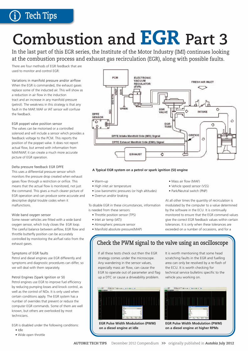
Check the PWM signal to the valve using an oscilloscope
If all these tests check out then the EGR
strategy comes under the microscope.
Any wandering in the sensor values,
especially mass air flow, can cause the
EGR to operate out of parameter and flag
up a DTC or cause a driveability problem.
It is worth mentioning that some head
scratching faults in the EGR and fuelling
area can only be resolved by a re-flash of
the ECU. It is worth checking for
technical service bulletins specific to the
vehicle you working on.
EGR Pulse Width Modulation (PWM)on a diesel engine at idle
EGR Pulse Width Modulation (PWM)on a diesel engine at higher RPMs
A Typical EGR system on a petrol or spark ignition (SI) engine
AUTOBIZ TECH TIPS December 2012 Compendium >> originally published in Autobiz July 2012
specific length of time, that the ECU will flag up
trouble codes relating to EGR.
Unfortunately, because the information from the
sensors is used to control other parts of the engine
management systems, the codes flagged up may
not directly identify an EGR fault, or an EGR fault
may be identified when a fault lies with a common
sensor.
Take, for instance, a faulty mass airflow meter. O2
sensor Lambda control allows the system to
operate with a slightly out of calibration MAF
sensor without putting the MIL on. The EGR
system is not always so tolerant of a faulty MAF,
and can cause driveability problems. Take a look at
short and long term fuel trim to see how accurate
the engine load parameter is.
Excessive EGR will dilute the air/fuel mixture and
make the engine run rough or stall. Excess flow
weakens combustion and may result in the
following conditions:
• Engine stalling after cold start
• Engine stalls at idle after deceleration
• Vehicle surges during cruise
• Rough idle
Excessive EGR will cause a rise in MAP. Use a
vacuum or scan tool to monitor manifold pressure.
It should be steady at between 3-400 mb (30-40
kPa) at idle. Higher than this and suspect a faulty
EGR or an air leak.
Insufficient EGR can allow combustion
temperatures to get too high during acceleration
and load conditions. This could cause:
• Pinging (pre-detonation of fuel)
• Engine overheating
• Emission test failure
A blocked exhaust will cause sufficient
backpressure, under load, to lift the EGR valve
and fill the manifold with exhaust gases. This
causes low power and an EGR feedback fault DTC.
On MAP/Speed sensed engines, it may
produce O2 sensor faults.
Look at EGR command and feedback on the scan
tool, check fuel trims and operation of the sensors
listed above.
Diesel Engines (Compression Ignition or CI)
Diesel engines use EGR to control NOx. Unlike a
petrol engine, EGR can be up to 60% of the
intake. Too much EGR will show itself under
acceleration as excessive black smoke. Diesel
engines rely on an accurate MAF value to monitor
EGR. In many systems, EGR feedback is
determined as the difference between calculated
gas flow (EGR + intake air)) and measured airflow.
The gas flow is calculated based on engine
capacity, speed, air pressure and temperature, This
shows how important the airflow value is. If the
airflow meter gives an air flow value greater than
actual, EGR would be commanded to increase and
the engine would be starved of air and black
smoke will come out of the exhaust.
Actuators: testing and diagnosing
When diagnosing EGR systems, most people are
more comfortable checking the mechanical bits
first. Fortunately, that’s where most problems lie.
For this you are going to need a vacuum gauge
and vacuum pump, or in the case of motorised
actuators, a scan tool. Apply a vacuum to the
actuator diaphragm. There should be a “clunk”
sound when vacuum is released. For peace of
mind, remove the EGR valve and bench test it. It
will give you an opportunity to inspect its action
and view the interior, especially the valve seat and
passages.
The most common problem is clogging of the
valve. This can happen naturally over time, or very
quickly when a fault occurs. Think about a
problem of a faulty airflow meter: Too much EGR
produces high levels of particulates which then re-
enter the engine through the EGR system, the
particulates act as seeds for bigger particulates to
latch onto and grow until the whole thing goes
into a vicious cycle of black smoke. The valve
eventually clogs with carbon, causing it to stick
either open, closed or partially open or to become
slow to react. EGR valves respond well to a good
de-coke, but look further into what caused it to
block in the first place.
When the passages are clear and the valve opens
and closes properly, then the task is to determine if
the valve is operating as commanded and if the
commands are based on good sensor data.
Understanding the operating strategy will help.
Check the electro/pneumatic valve for operation,
resistance and insulation. Use a vacuum gauge to
check the vacuum supplied from the vacuum
pump (diesel engine) or manifold (petrol engines).
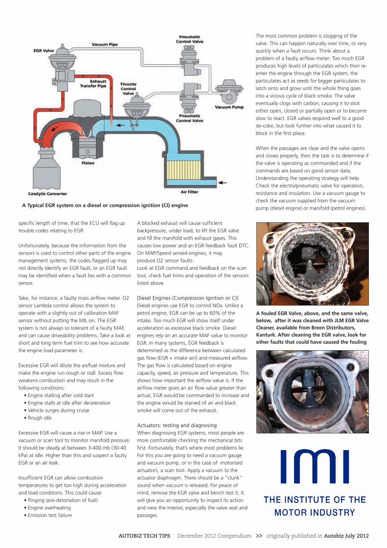
A fouled EGR Valve, above, and the same valve,below, after it was cleaned with JLM EGR ValveCleaner, available from Breen Distributors,Kanturk. After cleaning the EGR valve, look forother faults that could have caused the fouling
A Typical EGR system on a diesel or compression ignition (CI) engine
AUTOBIZ TECH TIPS December 2012 Compendium >> originally published in Autobiz July 2012