Embed Size (px)
Citation preview
techtopics revised 12/2014
1
Brakes and Automatic Slack Adjusters
>
TT03-1214
Brakes and Automatic Slack Adjusters
One of the challenges facing people adapting to the new ADR 38/04 specifications lies with the fitting and adjustment of automatic slack adjusters.
The automatic slack adjuster keeps the adjustment of the brakes in a clearly defined range to allow for normal wear and adjust the brakes accordingly
The first thing to remember is: An automatic slack adjuster does not set itself automatically – it automatically tries to keep the setting that it is given – often with disastrous results when it is not set correctly.
So we need to set the automatic slack adjuster correctly.
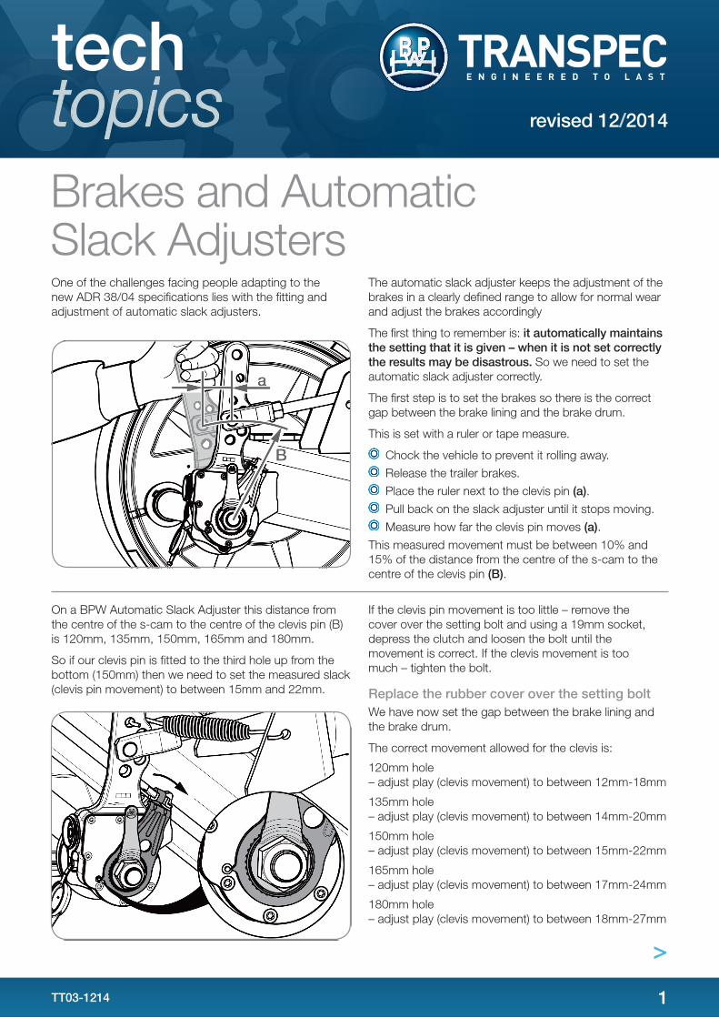
The first step is to set the brakes so there is the correct gap between the brake lining and the brake drum.
This is set with a ruler or tape measure.
• Chock the vehicle to prevent it rolling away. • Release the trailer brakes. • Place the ruler next to the clevis pin (a). • Pull back on the slack adjuster until it stops moving. • Measure how far the clevis pin moves (a).
This measured movement must be between 10% and 15% of the distance from the centre of the s-cam to the centre of the clevis pin (B).
One of the challenges facing people adapting to the new ADR 38/04 specifications lies with the fitting and adjustment of automatic slack adjusters.
The automatic slack adjuster keeps the adjustment of the brakes in a clearly defined range to allow for normal wear and adjust the brakes accordingly
The first thing to remember is: it automatically maintains the setting that it is given – when it is not set correctly the results may be disastrous. So we need to set the automatic slack adjuster correctly.
The first step is to set the brakes so there is the correct gap between the brake lining and the brake drum.
This is set with a ruler or tape measure.
Chock the vehicle to prevent it rolling away.
Release the trailer brakes.
Place the ruler next to the clevis pin (a).
Pull back on the slack adjuster until it stops moving.
Measure how far the clevis pin moves (a).
This measured movement must be between 10% and 15% of the distance from the centre of the s-cam to the centre of the clevis pin (B).
On a BPW Automatic Slack Adjuster this distance from the centre of the s-cam to the centre of the clevis pin (B) is 120mm, 135mm, 150mm, 165mm and 180mm.
So if our clevis pin is fitted to the third hole up from the bottom (150mm) then we need to set the measured slack (clevis pin movement) to between 15mm and 22mm.
If the clevis pin movement is too little – remove the cover over the setting bolt and using a 19mm socket, depress the clutch and loosen the bolt until the movement is correct. If the clevis movement is too much – tighten the bolt.
Replace the rubber cover over the setting bolt.
We have now set the gap between the brake lining and the brake drum.
The correct movement allowed for the clevis is:
120mm hole – adjust play (clevis movement) to between 12mm-18mm
135mm hole – adjust play (clevis movement) to between 14mm-20mm
150mm hole – adjust play (clevis movement) to between 15mm-22mm
165mm hole – adjust play (clevis movement) to between 17mm-24mm
180mm hole – adjust play (clevis movement) to between 18mm-27mm
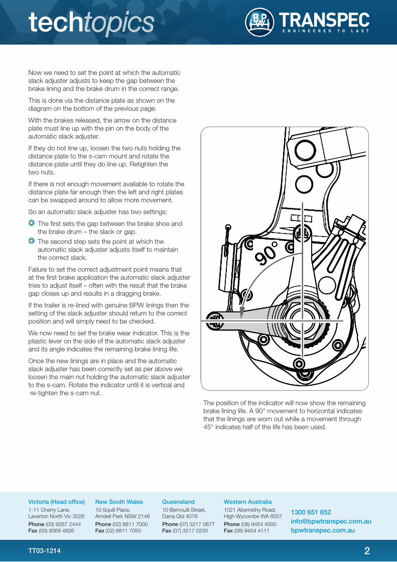
Now we need to set the point at which the automatic slack adjuster adjusts to keep the gap between the brake lining and the brake drum in the correct range.
This is done via the distance plate as shown above.
On a BPW Automatic Slack Adjuster this distance from the centre of the s-cam to the centre of the clevis pin (B) is 120mm, 135mm, 150mm, 165mm and 180mm.
So if our clevis pin is fitted to the third hole up from the bottom (150mm) then we need to set the measured slack (clevis pin movement) to between 15mm and 22mm.
If the clevis pin movement is too little – remove the cover over the setting bolt and using a 19mm socket, depress the clutch and loosen the bolt until the movement is correct. If the clevis movement is too much – tighten the bolt.
Replace the rubber cover over the setting boltWe have now set the gap between the brake lining and the brake drum.
The correct movement allowed for the clevis is:
120mm hole – adjust play (clevis movement) to between 12mm-18mm
135mm hole – adjust play (clevis movement) to between 14mm-20mm
150mm hole – adjust play (clevis movement) to between 15mm-22mm
165mm hole – adjust play (clevis movement) to between 17mm-24mm
180mm hole – adjust play (clevis movement) to between 18mm-27mm
2
techtopics
Now we need to set the point at which the automatic slack adjuster adjusts to keep the gap between the brake lining and the brake drum in the correct range.
This is done via the distance plate as shown on the diagram on the bottom of the previous page.
With the brakes released, the arrow on the distance plate must line up with the pin on the body of the automatic slack adjuster.
If they do not line up, loosen the two nuts holding the distance plate to the s-cam mount and rotate the distance plate until they do line up. Retighten the two nuts.
If there is not enough movement available to rotate the distance plate far enough then the left and right plates can be swapped around to allow more movement.
So an automatic slack adjuster has two settings:
The first sets the gap between the brake shoe and the brake drum – the slack or gap.
The second step sets the point at which the automatic slack adjuster adjusts itself to maintain the correct slack.
Failure to set the correct adjustment point means that at the first brake application the automatic slack adjuster tries to adjust itself – often with the result that the brake gap closes up and results in a dragging brake.
If the trailer is re-lined with genuine BPW linings then the setting of the slack adjuster should return to the correct position and will simply need to be checked.
We now need to set the brake wear indicator. This is the plastic lever on the side of the automatic slack adjuster and its angle indicates the remaining brake lining life.
Once the new linings are in place and the automatic slack adjuster has been correctly set as per above we loosen the main nut holding the automatic slack adjuster to the s-cam. Rotate the indicator until it is vertical and re-tighten the s-cam nut.
The position of the indicator will now show the remaining brake lining life. A 90° movement to horizontal indicates that the linings are worn out while a movement through 45° indicates half of the life has been used.
1300 651 [email protected]
Victoria (Head office)1-11 Cherry Lane, Laverton North Vic 3026
Phone (03) 9267 2444 Fax (03) 9369 4826
New South Wales10 Squill Place, Arndell Park NSW 2148
Phone (02) 8811 7000 Fax (02) 8811 7050
Queensland10 Bernoulli Street, Darra Qld 4076
Phone (07) 3217 0877 Fax (07) 3217 0230
Western Australia1021 Abernethy Road, High Wycombe WA 6057
Phone (08) 9454 4000 Fax (08) 9454 4111
TT03-1214
The position of the indicator will now show the remaining brake lining life. A 90° movement to horizontal indicates that the linings are worn out while a movement through 45° indicates half of the life has been used.


![ECE 6504: Deep Learning for Perception Dhruv Batra Virginia Tech Topics: –LSTMs (intuition and variants) –[Abhishek:] Lua / Torch Tutorial](https://img.pdfslide.net/doc/110x75/5a4d1b047f8b9ab059987cd9/ece-6504-deep-learning-for-perception-dhruv-batra-virginia-tech-topics-lstms.jpg)