Embed Size (px)
Citation preview
Teaching GuidanceGroundwater development and Management
Capacity Development ProjectDDCAP
1: Objectives
2. Contents
3. Teaching Methods
4. Materials
3-1
3-1M1 Drilling Chap. 6 P218-219
Technical Area: 3 Drilling Drawbacks
Item: 3-1 Countermeasures against lost circulation during mud drilling
To be able to explain and advise for how to prevent from lost circulation and countermeasuresagainst it during mud drilling.
- Phenomenan of lost circulation- countermeasure against lost circulation
(1) Explain phenmenan of lost circulation and lost circulation formation.(2) Explain how to remedy for circulation loss.


3-1M1 - 1
3-1M1 - 2
Teaching GuidanceGroundwater development and Management
Capacity Development ProjectDDCAP
1: Objectives
2. Contents
3. Teaching Methods
4. Materials
3-2
See 3-1M1
Technical Area: 3 Drilling Drawbacks
Item: 3-2 Countermeasures against lost circulation during DTH drilling
To be able to explain and advise for how to prevent from lost circulation and countermeasuresagainst it during DTH drilling.
- Phenomenan of lost circulation- countermeasure against lost circulation
(1) Explain phenmenan of lost circulation and lost circulation formation.(2) Explain how to remedy for circulation loss.

Teaching GuidanceGroundwater development and Management
Capacity Development ProjectDDCAP
1: Objectives
2. Contents
3. Teaching Methods
4. Materials
3-3
3-3M1 Drilling Chap. 6 P215-P218
Technical Area: 3 Drilling Drawbacks
Item: 3-3 Countermeasures against bore wall collapse during mud drilling
To be able to explain and advise for how to prevent from bore wall collapse and countermeasuresagainst it during mud drilling.
- Prevention of bore wall collapse- countermeasure against borehole collapse
(1) Explain phenomenan of borehole collapse.(2)Explain the measures for stabilization of bore wall.

3-3M1 - 1
3-3M1 - 2
3-3M1 - 3
3-3M1 - 4
Teaching GuidanceGroundwater development and Management
Capacity Development ProjectDDCAP
1: Objectives
2. Contents
3. Teaching Methods
4. Materials
3-4
See 3-3M1
Technical Area: 3 Drilling Drawbacks
Item: 3-4 Countermeasures against bore wall collapse during DTH drilling
To be able to explain and advise for how to prevent from bore wall collapse and countermeasuresagainst it during DTH drilling.
- Prevention of bore wall collapse- countermeasure against borehole collapse
(1) Explain phenomenan of borehole collapse.(2)Explain the measures for stabilization of bore wall.

Teaching GuidanceGroundwater development and Management
Capacity Development ProjectDDCAP
1: Objectives
2. Contents
3. Teaching Methods
4. Materials
3-5
3-5M1 Drilling Chap. 12 P514-517
Technical Area: 3 Drilling Drawbacks
Item: 3-5 Countermeasures against jamming of drilling tools
To be able to explain and advise for how to prevent from jamming of drilling tools andcountermeasures to recover it.
-Prevention of jamming- Countermeasure against jamming
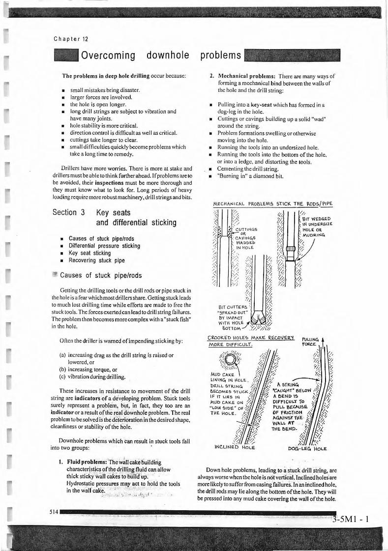
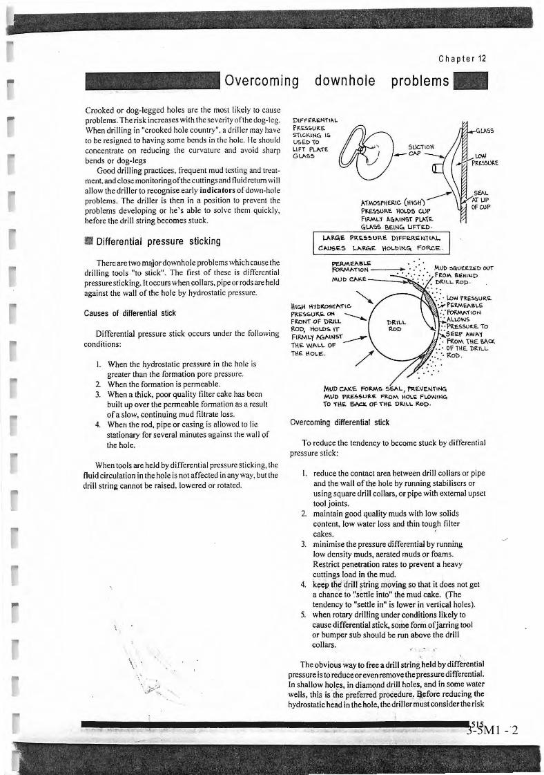
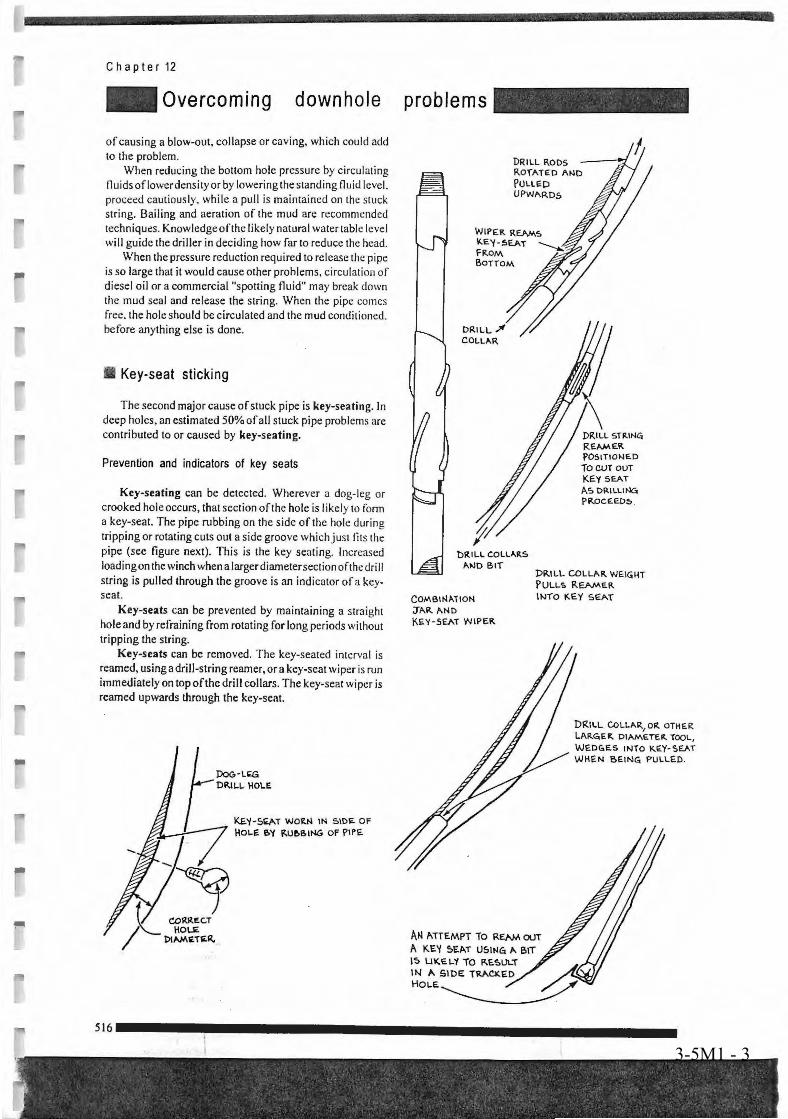
(1) Explain causes of jamming such as colllapse, key seasts, under gauge, dog-leg etc. using manual.(2) Explain countermeasure against jamming.

3-5M1 - 1
3-5M1 - 2
3-5M1 - 3
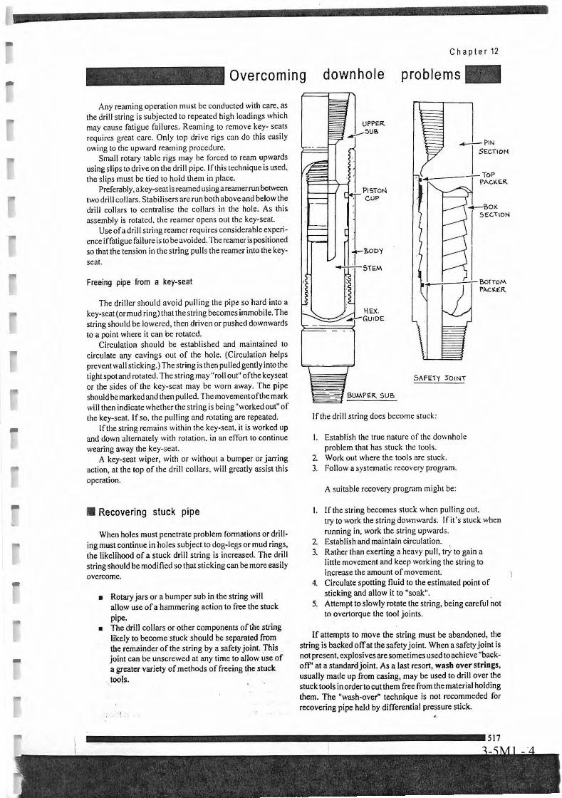
3-5M1 - 4
Teaching GuidanceGroundwater development and Management
Capacity Development ProjectDDCAP
1: Objectives
2. Contents
3. Teaching Methods
4. Materials
4-1
4-1M1 DDCA's Manual for Drilling Works4-1M2 Drilling Chap. 6 P197-P208
Technical Area: 4 Drilling Control
Item: 4-1 Mud control
To be able to explain and advise for rolls of mud fluid to conduct effective drilling and how to keepcondition of mud.
- Mud agent- Function of mud- Annular velocity- Mud mixing- Mud control equipment- Mud control according to geological conditions
(1) Explain the use and mixing ratio of mud agent such as bentonite, polimer etc. using manual.(2) Explain function of mud circulation such as removal of cuttings, wall stabilization, lubricationetc. using manual.(3) Explain mud circulation equipment and system using manual.(4) Explain how to keep mud conditions according to geological conditions.(5) Explain how to use funnel viscosimeter and mud balance.

DDCAP Technical Manual for Drilling Works For Technical Support Plan for the Drillers in DDCA
4-1M1 - 1
3 DRILLING CONTROL (TA CODE 4)
3.1 MUD CONTROL (A CODE 4-1)
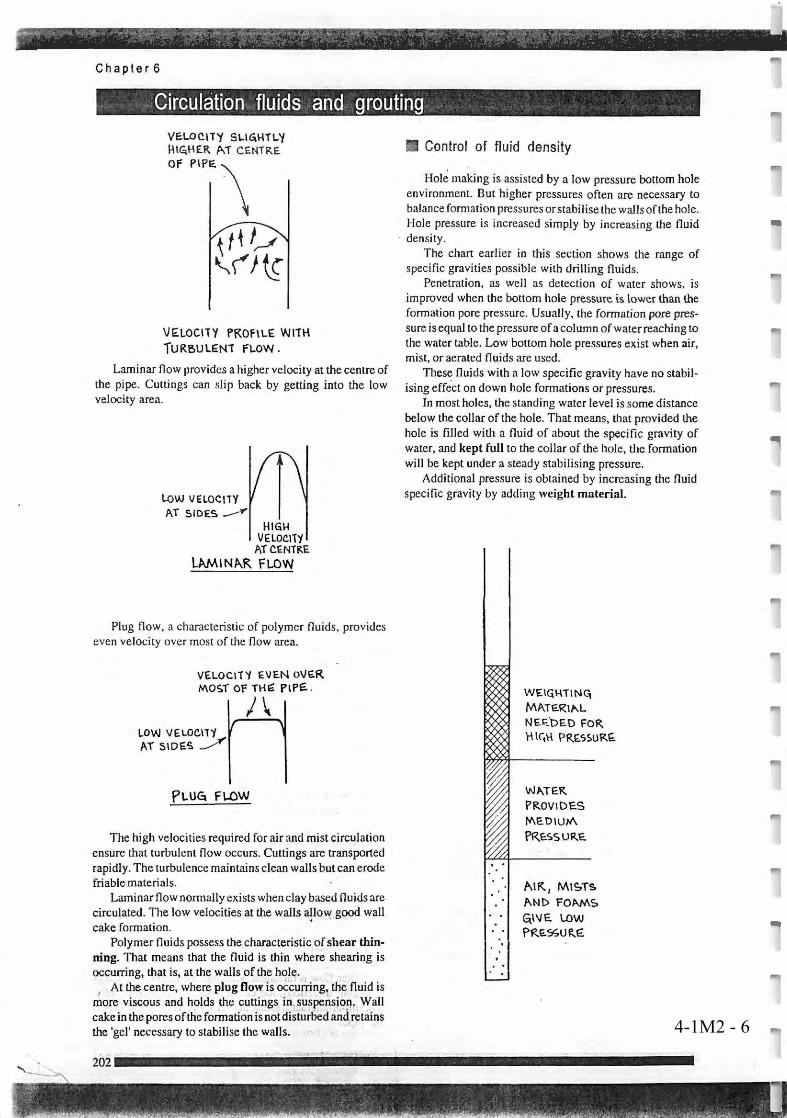
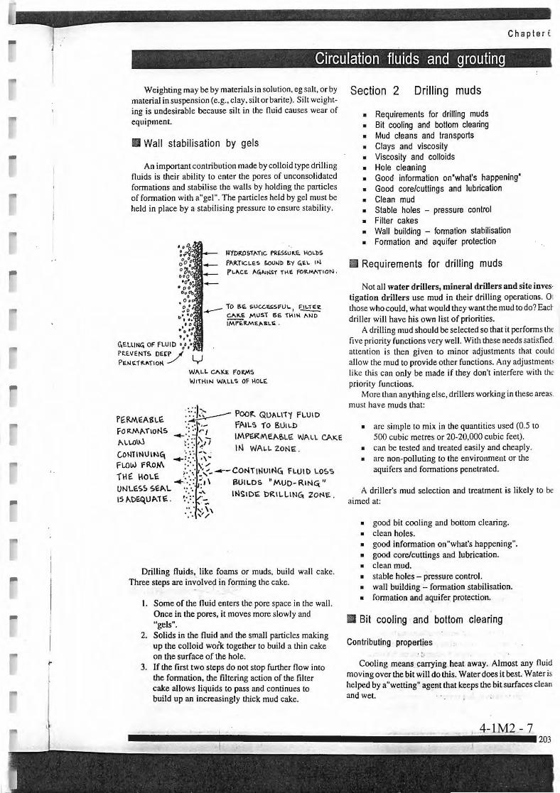
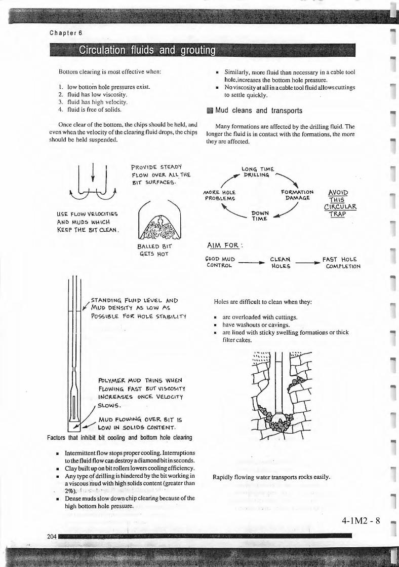
The roll of mud circulation is as follows: − Prevension from wall collapse − Removal of drill cuttings from the hole − Prevension from flow-in of groundwater − Prevension form lost circulation − Cleaning and cooling of bit − Reducing the friction of bit rotation
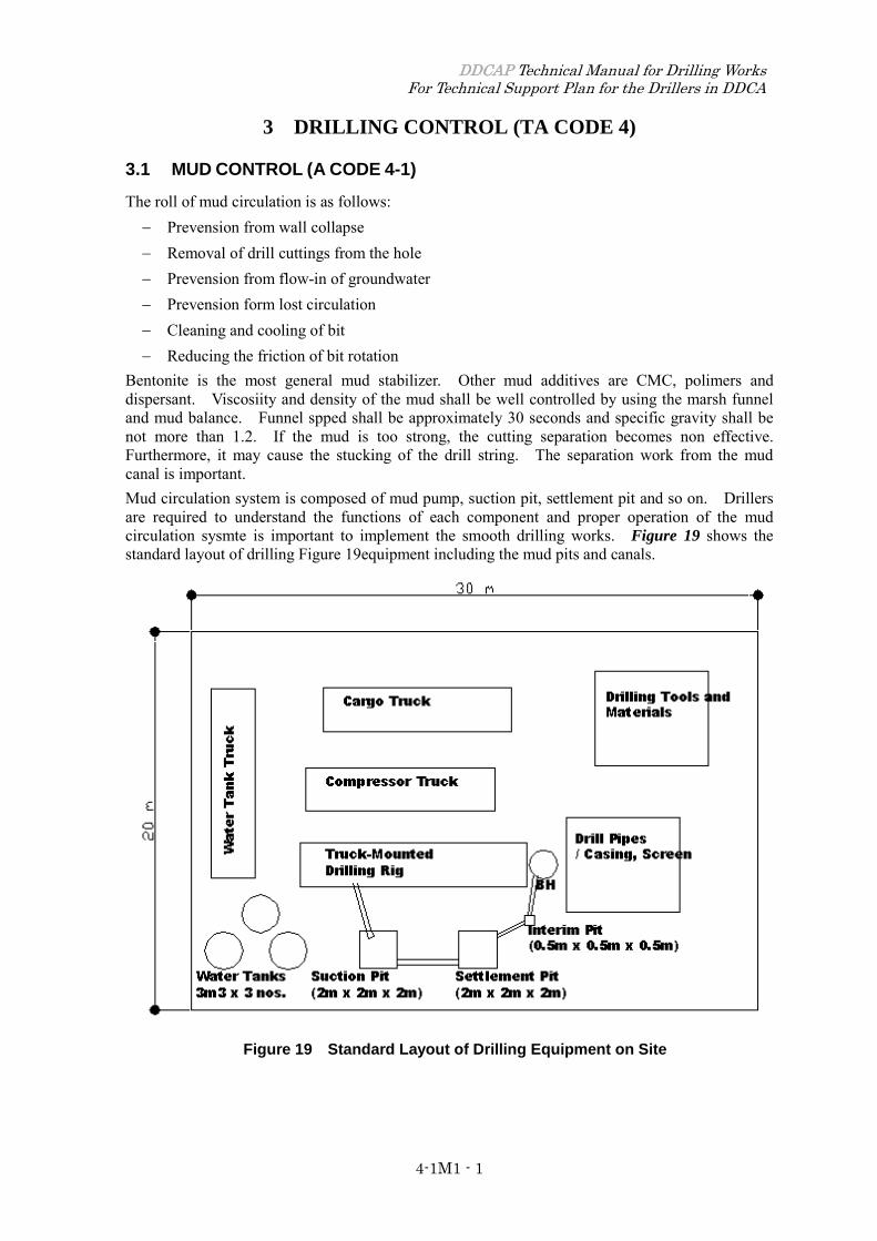
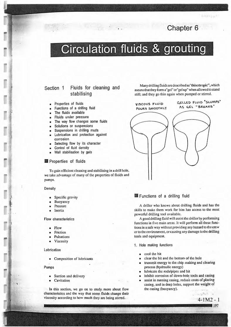
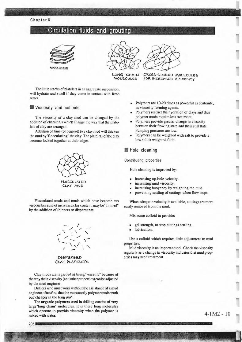
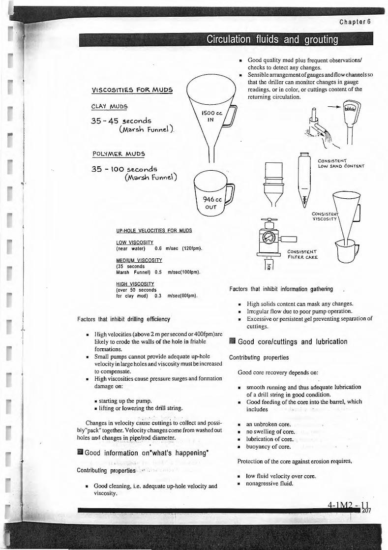
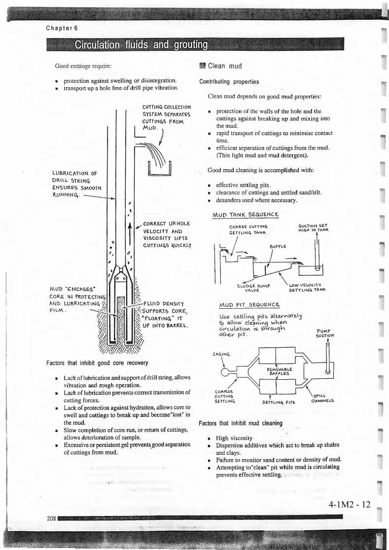
Bentonite is the most general mud stabilizer. Other mud additives are CMC, polimers and dispersant. Viscosiity and density of the mud shall be well controlled by using the marsh funnel and mud balance. Funnel spped shall be approximately 30 seconds and specific gravity shall be not more than 1.2. If the mud is too strong, the cutting separation becomes non effective. Furthermore, it may cause the stucking of the drill string. The separation work from the mud canal is important. Mud circulation system is composed of mud pump, suction pit, settlement pit and so on. Drillers are required to understand the functions of each component and proper operation of the mud circulation sysmte is important to implement the smooth drilling works. Figure 19 shows the standard layout of drilling Figure 19equipment including the mud pits and canals.
Figure 19 Standard Layout of Drilling Equipment on Site

4-1M2 - 1
4-1M2 - 2
4-1M2 - 3
4-1M2 - 4
4-1M2 - 5
4-1M2 - 6
4-1M2 - 7
4-1M2 - 8
4-1M2 - 9
4-1M2 - 10
4-1M2 - 11
4-1M2 - 12
Teaching GuidanceGroundwater development and Management
Capacity Development ProjectDDCAP
1: Objectives
2. Contents
3. Teaching Methods
4. Materials
4-2
4-2M1 DDCA's Manual for Drilling Works
Technical Area: 4 Drilling Control
Item: 4-2 Mud Pump Operation
To be able to explain and advise for how to operate mud pump for effective use.
- Mud Pump Operation
(1) Explain structure and components of mud pump using operation manual.(2) Explain capacity (discharge rate and pressure) of mud pump using capacity curve.(3) Explain precautions for mud pump operation using check-list

DDCAP Technical Manual for Drilling Works For Technical Support Plan for the Drillers in DDCA
4-2M1 - 1
3.2 MUD PUMP OPERATION (TA CODE 4-2)
The discharge rate of mud pump is important for the removal of the drill cuttings. Usual cares shall be taken on the worn out of the parts of the mud pump, because it decreases the discharge rate. In case that the discharge rate decreases during drilling, drill string shall be raised up to the depth up to the safe depth (in the casing) to check the mud pump.
The pump pressure shall be kept recorded as it is an important parameters to identify the borehole conditions. The variation of the pump pressure indicates the following conditions:
Increase of the pressure: − Encountering clayey formations − Mud visicosity and/or density is elevated − Bore wall collapse − Drill cuttings remains in the hole − Bit is covered by the clay − According to the increase of depth
Decrease of the pressure: − Breakdown of the mud pump − Mud viscosity and/or density is decreased − Lost circulation − Encountering sandy formations
Please refer to Technical Item 2-4 for the further specifications and structure of the mud pump.


Teaching GuidanceGroundwater development and Management
Capacity Development ProjectDDCAP
1: Objectives
2. Contents
3. Teaching Methods
4. Materials
4-3
4-3M1 DDCA's Manual for Drilling Works
Technical Area: 4 Drilling Control
Item: 4-3 Casing for mud drilling
To be able to explain and advise for specifications of surface and conductor casings and procedure toinstall and remove them.
- Surface casing- Conductor casing- Casing installation and removal
(1) Explain specification of steel pipes (inside and out diameters, thickness, unit weight, unit length)using specification list of steel pipes.(2) Explain procedure of casing installation.(3) Explain procedure of casing removal.

DDCAP Technical Manual for Drilling Works For Technical Support Plan for the Drillers in DDCA
4-3M1 - 1
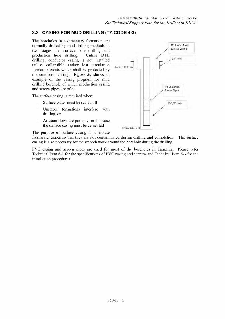
3.3 CASING FOR MUD DRILLING (TA CODE 4-3)
The boreholes in sedimentary formation are normally drilled by mud drilling methods in two stages, i.e. surface hole drilling and production hole drilling. Unlike DTH drilling, conductor casing is not installed unless collapsible and/or lost circulation formation exists which shall be protected by the conductor casing. Figure 20 shows an example of the casing program for mud drilling borehole of which production casing and screen pipes are of 6”.
The surface casing is required when: − Surface water must be sealed off − Unstable formations interfere with
drilling, or − Artesian flows are possible. in this case
the surface casing must be cemented
The purpose of surface casing is to isolate freshwater zones so that they are not contaminated during drilling and completion. The surface casing is also necessary for the smooth work around the borehole during the drilling.
PVC casing and screen pipes are used for most of the boreholes in Tanzania. Please refer Technical Item 6-1 for the specifications of PVC casing and screens and Technical Item 6-3 for the installation procedures.


Teaching GuidanceGroundwater development and Management
Capacity Development ProjectDDCAP
1: Objectives
2. Contents
3. Teaching Methods
4. Materials
4-4
4-4M1 DDCA's Manual for Drilling Works4-4M2 Drilling Chap. 7 P274-284
Technical Area: 4 Drilling Control
Item: 4-4 Drilling operation for mud drilling
To be able to explain and advise for how to control various parameter of drilling and procedures ofeach work such as pipe connection, cleaning hole etc.
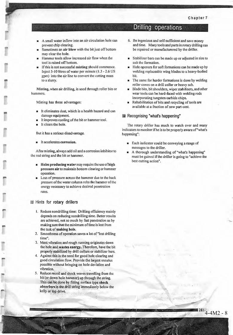
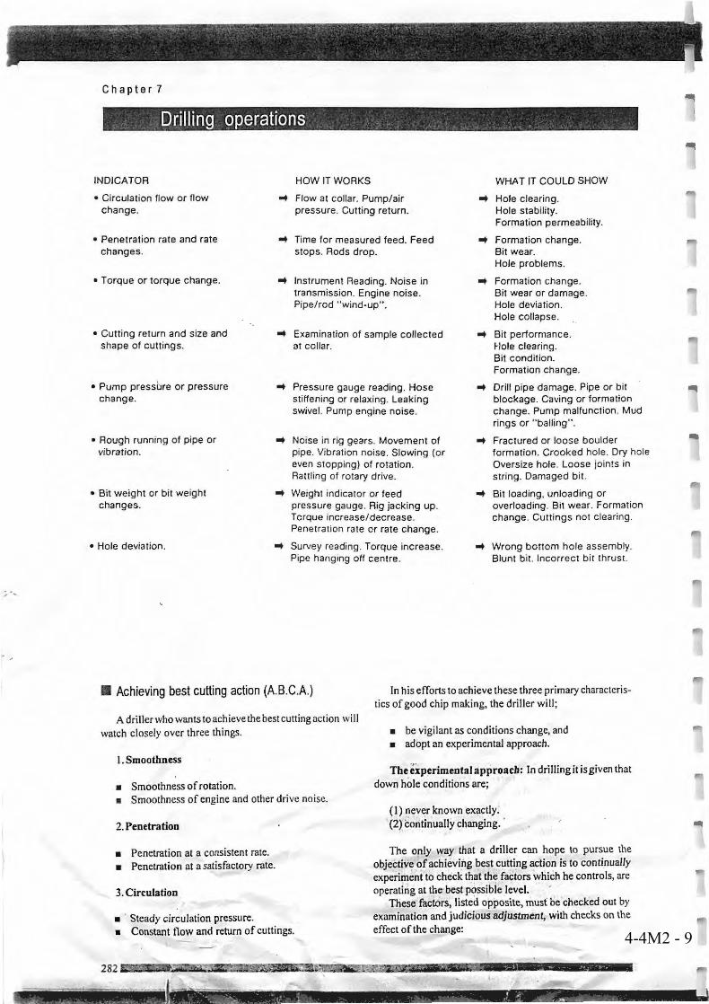
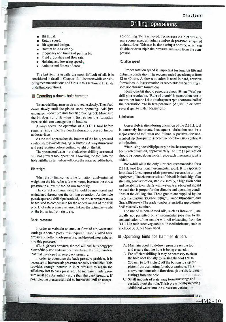
- Weight on bit- Rotation speed- Drill pipe connection- Pipe retrieval- Drilling log- Reaming hole- Cleaning hole
(1) Explain standard weight on bit to be loaded and rotation speed according to hole diameter andgeological condition using manual.(2) Explain procedure of drill pipe connection and pipe retrieval.(3) Explain how to keep drilling log using record format.(4) Explain necessity of reaming and cleaning of hole and precautions for the work, using manual(5) Explain rig operation using operation manual and daily service check-sheet

DDCAP Technical Manual for Drilling Works For Technical Support Plan for the Drillers in DDCA
4-4M1 - 1
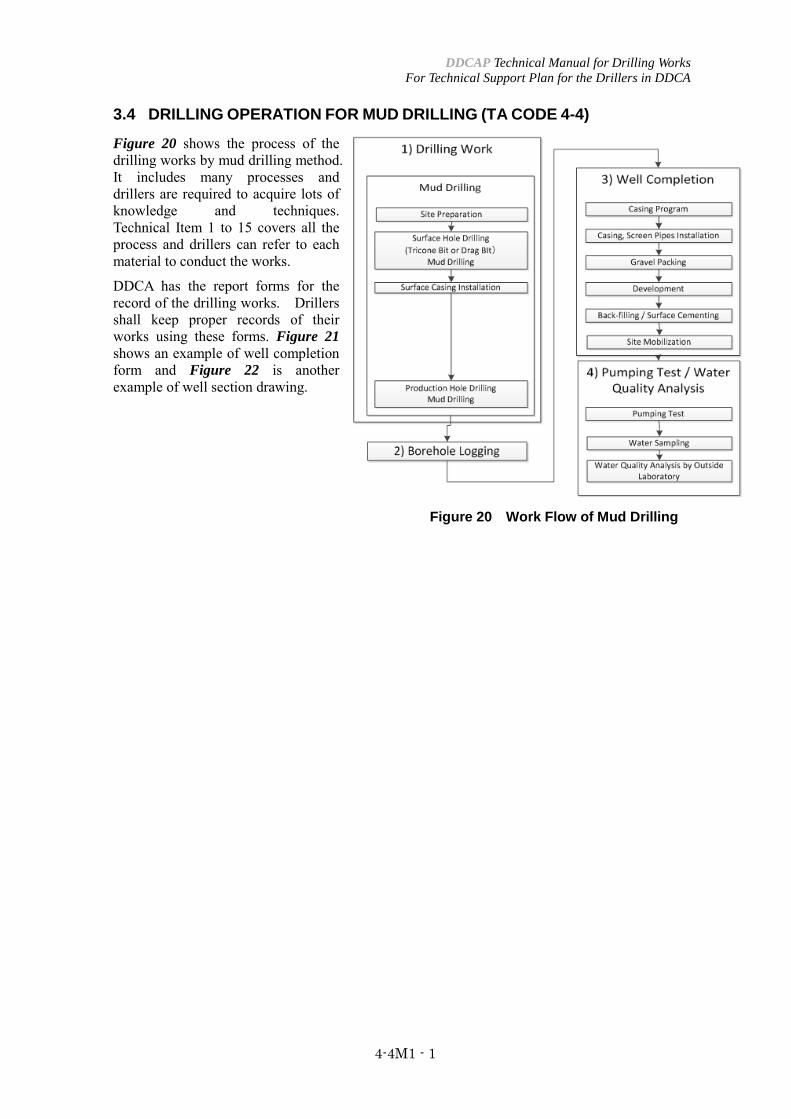
3.4 DRILLING OPERATION FOR MUD DRILLING (TA CODE 4-4)
Figure 20 shows the process of the drilling works by mud drilling method. It includes many processes and drillers are required to acquire lots of knowledge and techniques. Technical Item 1 to 15 covers all the process and drillers can refer to each material to conduct the works.
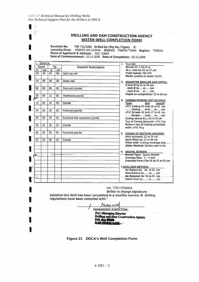
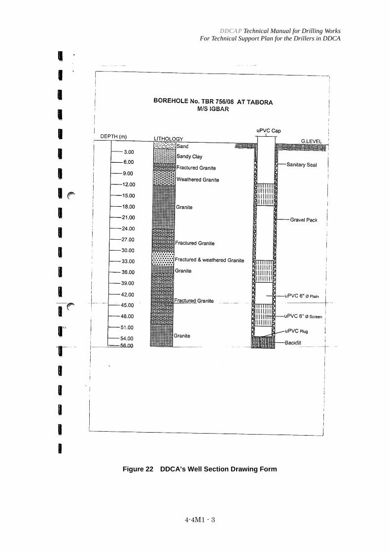
DDCA has the report forms for the record of the drilling works. Drillers shall keep proper records of their works using these forms. Figure 21 shows an example of well completion form and Figure 22 is another example of well section drawing.
Figure 20 Work Flow of Mud Drilling
DDCAP Technical Manual for Drilling Works For Technical Support Plan for the Drillers in DDCA
4-4M1 - 2
Figure 21 DDCA’s Well Completion Form
DDCAP Technical Manual for Drilling Works For Technical Support Plan for the Drillers in DDCA
4-4M1 - 3
Figure 22 DDCA’s Well Section Drawing Form

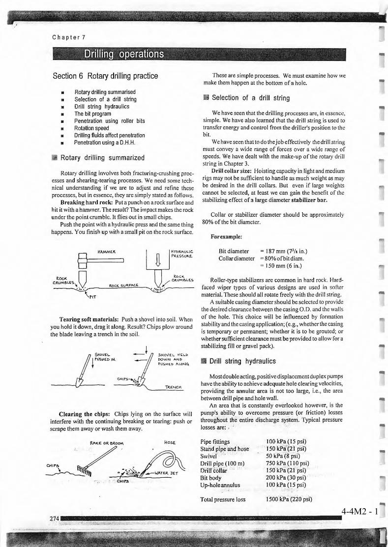
4-4M2 - 1
4-4M2 - 2
4-4M2 - 3
4-4M2 - 4
4-4M2 - 5
4-4M2 - 6
4-4M2 - 7
4-4M2 - 8
4-4M2 - 9
4-4M2 - 10

4-4M2 - 11


Teaching GuidanceGroundwater development and Management
Capacity Development ProjectDDCAP
1: Objectives
2. Contents
3. Teaching Methods
4. Materials
4-5
4-5M1 DDCA's Manual for Drilling Works
Technical Area: 4 Drilling Control
Item: 4-5 Bit control and repairing for mud drilling
To be able to explain and advise for how to control and repair bits for effective use.
-Bit control- Bit repairing
(1) Explain how to control bit numbers and check bit conditions using bit log form.(2) Explain how to recondition roller bits and blade bits using manual.

DDCAP Technical Manual for Drilling Works For Technical Support Plan for the Drillers in DDCA
4-5M1 - 1
3.5 BIT CONTROL AND REPARING FOR MUD DRILLING (TA CODE 4-5)
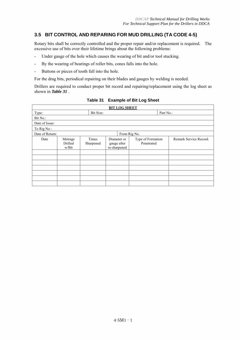
Rotary bits shall be correctly controlled and the proper repair and/or replacement is required. The excessive use of bits over their lifetime brings about the following problems:
- Under gauge of the hole which causes the wearing of bit and/or tool stucking.
- By the wearing of bearings of roller bits, cones falls into the hole.
- Buttons or pieces of tooth fall into the hole.
For the drag bits, periodical repairing on their blades and gauges by welding is needed.
Drillers are required to conduct proper bit record and repairing/replacement using the log sheet as shown in Table 31 .
Table 31 Example of Bit Log Sheet BIT LOG SHEET
Type: Bit Size: Part No.: Bit No.: Date of Issue: To Rig No.: Date of Return: From Rig No.
Date Metrage Drilled w/Bit
Times Sharpened
Diameter or gauge after
re-sharpened
Type of Formation Penetrated
Remark Service Record.

Teaching GuidanceGroundwater development and Management
Capacity Development ProjectDDCAP
1: Objectives
2. Contents
3. Teaching Methods
4. Materials
4-6
4-6M1 DDCA's Manual for Drilling Works
Technical Area: 4 Drilling Control
Item: 4-6 Air control for DTH drilling
To be able to explain and advise for rolls of air and how to control pressure and delivery foreffective DTH drilling.
- Air delivery and pressure- Annular velocity- Air control for DTH drilling
(1) Explain proper air delivery and pressure according to size of DTH and DTH bits using operationmanual.(2) Explain how to calculate annualar velocity and necessary velocity to remove cuttings.(3) Explain how to regulate air according to drilling conditions using manual.

DDCAP Technical Manual for Drilling Works For Technical Support Plan for the Drillers in DDCA
4-6M1 - 1
3.6 AIR CONTROL FOR DTH DRILLING (TA CODE 4-6)
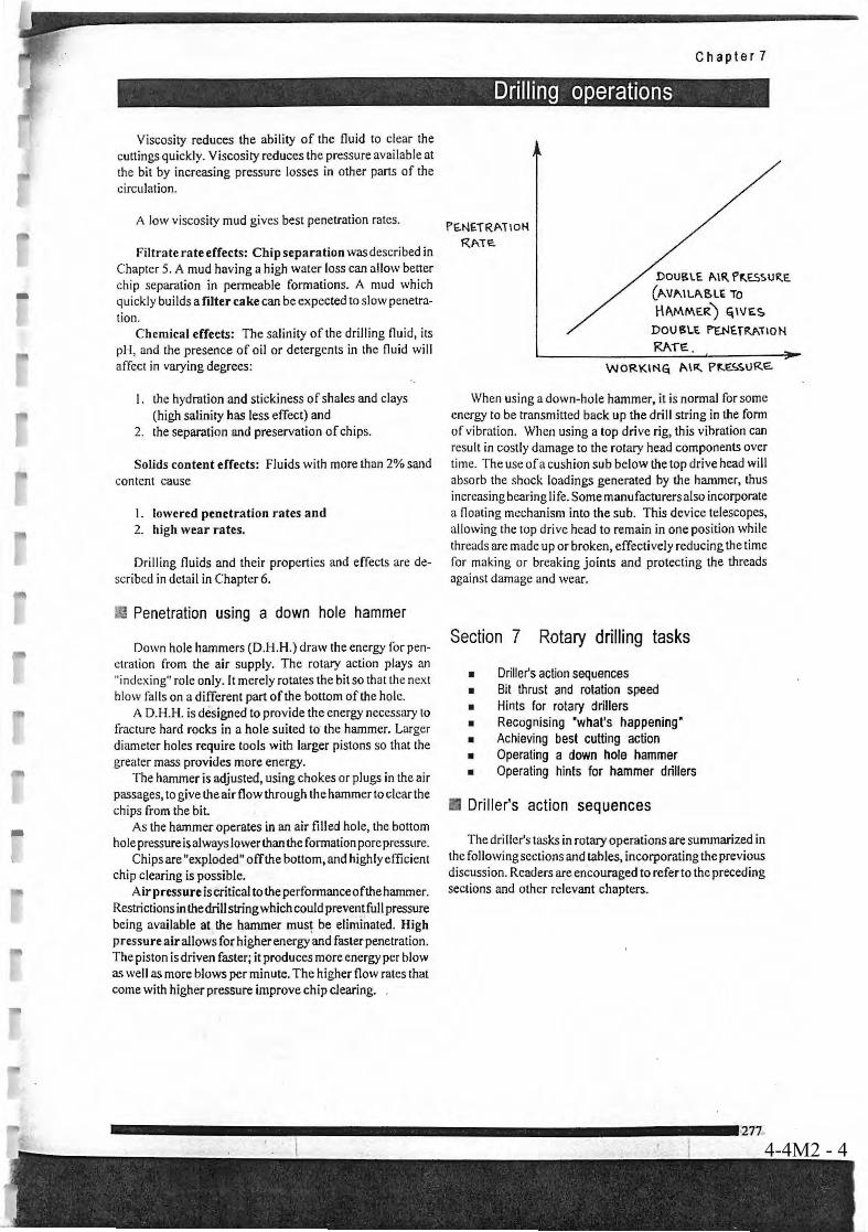
It can be observed that drilling with Megadrills and Megabits do by far not reach the performance recommended by the manufacturer of the tools. Low penetration rate may result from problem of different nature of operation of Megadrills and bits such as: − Air supply is not according to requirement resulting in not adequate air pressure in the
Megadrill or air volume is not less than 1,200 m per minute or air pressure required for A 53-15 Megadrill not less than 9.0 to 10.3 bar.
− The drill bit is not sharpened properly − The Megadrill is worn-out, clearance of piston and piston case sealing O- rings worn-out etc. − Bits are very dully because of overrunning − The necessary bit weight is not on the bit or there is too much load on the bit (for A 53-15
Megadrills 680 kg minimum weight and 1,600 kg maximum weight (is recommended). − Rotation of bit is not according to the geological formation and to the expected penetration
rate per revolution. Ideally the bit should penetrate 3/8"into the formation of the drill pipe. Generally acceptable revolution per minute are considered with 15rpm to 30rpm
− No use of water injection will create problems of “collaring” or bridging caused by scopage of small amounts of formation water into the hole. To be avoided by injecting 2 to 5 CPM of water into the air stream.
− The “back pressure” created by considerable formation water influx may reduce extremely the penetration rate. To overcome this problem form has to be used in quantities.
Drillers are required to understand the mechanism and function of the air-compressor and the DTH using the operation manual of the manufacturers. They have to consider the static water pressure, back-pressure, annular velocity necessary to remove the cuttings from the borehole and conduct proper operation of the air-compressor.

Teaching GuidanceGroundwater development and Management
Capacity Development ProjectDDCAP
1: Objectives
2. Contents
3. Teaching Methods
4. Materials
4-7
4-7M1 DDCA's Manual for Drilling Works
Technical Area: 4 Drilling Control
Item: 4-7 Air compressor operation
To be able to explain and advise for how to operate air compressor for effective use.
- Air compressor operation
(1) Explain precautions for air compressor operation using operation manual


DDCAP Technical Manual for Drilling Works For Technical Support Plan for the Drillers in DDCA
4-7M1 - 1
3.7 AIR COMPRESSOR OPERATION (TA CODE 4-7)
The specifications and structure of the air-compressor are described in Technical Item 2-4. The air-compressor is the major and important equipment for the DTH drilling. Therefore, the drillers are required to acquire the knowledge of the functions, maintenance and operation of the air-compressor. Please refer to other section of this manual related to the DTH drilling, for further comprehension of the operation of the air-compressor.

Teaching GuidanceGroundwater development and Management
Capacity Development ProjectDDCAP
1: Objectives
2. Contents
3. Teaching Methods
4. Materials
4-8
4-8M1 DDCA's Manual for Drilling Works
Technical Area: 4 Drilling Control
Item: 4-8 Casing for DTH drilling
To be able to explain and advise for specifications of surface and conductor casings and procedure toinstall and remove them.
- Surface casing- Conductor casing- Casing installation and removal
(1) Explain specification of steel pipes (inside and out diameters, thickness, unit weight, unit length)using specification list of steel pipes.(2) Explain procedure of casing installation.(3) Explain procedure of casing removal.

DDCAP Technical Manual for Drilling Works For Technical Support Plan for the Drillers in DDCA
4-8M1 - 1
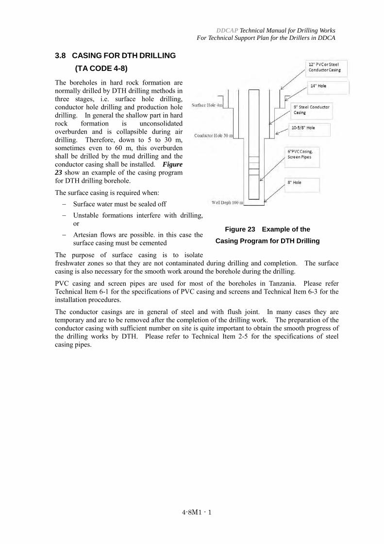
3.8 CASING FOR DTH DRILLING
(TA CODE 4-8)
The boreholes in hard rock formation are normally drilled by DTH drilling methods in three stages, i.e. surface hole drilling, conductor hole drilling and production hole drilling. In general the shallow part in hard rock formation is unconsolidated overburden and is collapsible during air drilling. Therefore, down to 5 to 30 m, sometimes even to 60 m, this overburden shall be drilled by the mud drilling and the conductor casing shall be installed. Figure 23 show an example of the casing program for DTH drilling borehole.
The surface casing is required when: − Surface water must be sealed off − Unstable formations interfere with drilling,
or − Artesian flows are possible. in this case the
surface casing must be cemented
The purpose of surface casing is to isolate freshwater zones so that they are not contaminated during drilling and completion. The surface casing is also necessary for the smooth work around the borehole during the drilling.
PVC casing and screen pipes are used for most of the boreholes in Tanzania. Please refer Technical Item 6-1 for the specifications of PVC casing and screens and Technical Item 6-3 for the installation procedures.
The conductor casings are in general of steel and with flush joint. In many cases they are temporary and are to be removed after the completion of the drilling work. The preparation of the conductor casing with sufficient number on site is quite important to obtain the smooth progress of the drilling works by DTH. Please refer to Technical Item 2-5 for the specifications of steel casing pipes.
Figure 23 Example of the Casing Program for DTH Drilling

Teaching GuidanceGroundwater development and Management
Capacity Development ProjectDDCAP
1: Objectives
2. Contents
3. Teaching Methods
4. Materials
4-9
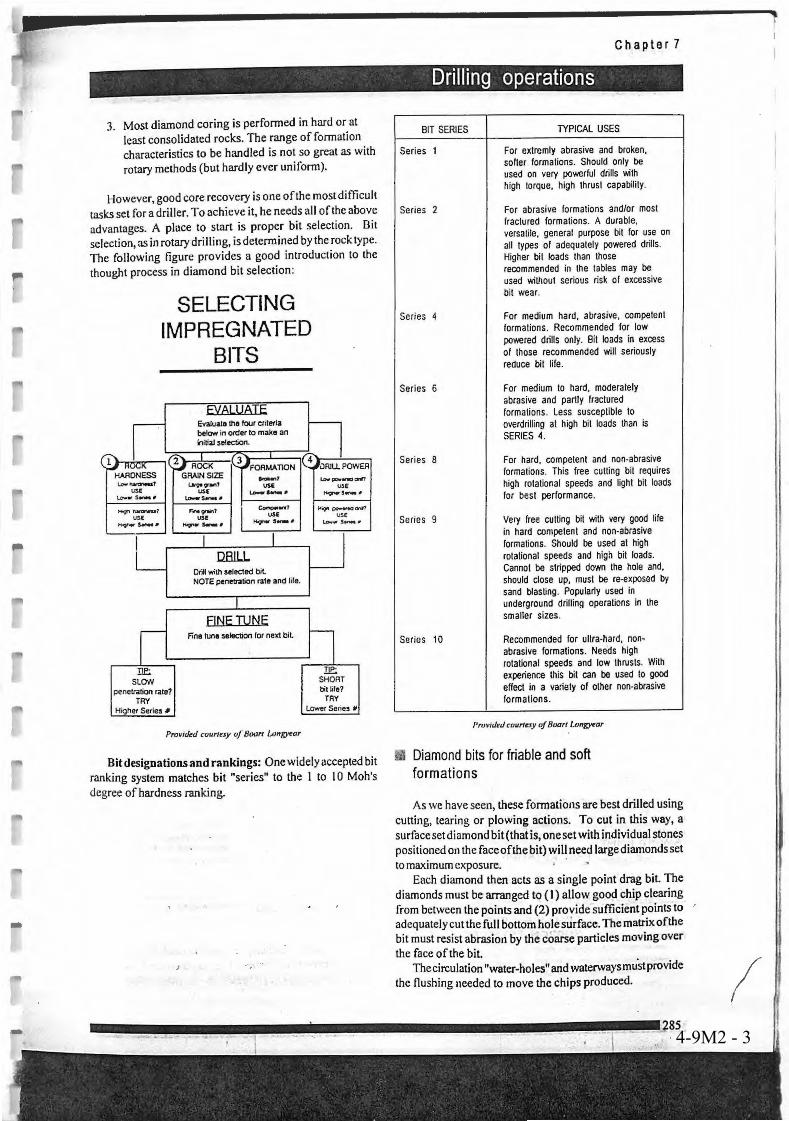
4-9M1 DDCA's Manual for Drilling Works4-9M2 Drilling Chap. 7 P283-P285
Technical Area: 4 Drilling Control
Item: 4-9 Drilling operation for DTH drilling
To be able to explain and advise for how to control various parameter of drilling and procedures ofeach work such as pipe connection, cleaning hole etc.
- Weight on bit- Rotation speed- Drill pipe connection- Pipe retrieval- Drilling log- Reaming hole- Cleaning hole
(1) Explain standard weight on bit to be loaded and rotation speed according to hole diameter andgeological condition using manual.(2) Explain procedure of drill pipe connection and pipe retrieval.(3) Explain how to keep drilling log using record format.(4) Explain necessity of reaming and cleaning of hole and precautions for the work, using manual(5) Explain rig operation using operation manual and daily service check-sheet

DDCAP Technical Manual for Drilling Works For Technical Support Plan for the Drillers in DDCA
4-9M1 - 1
3.9 DRILLING OPERATION FOR DTH DRILLING (TA CODE 4-9)
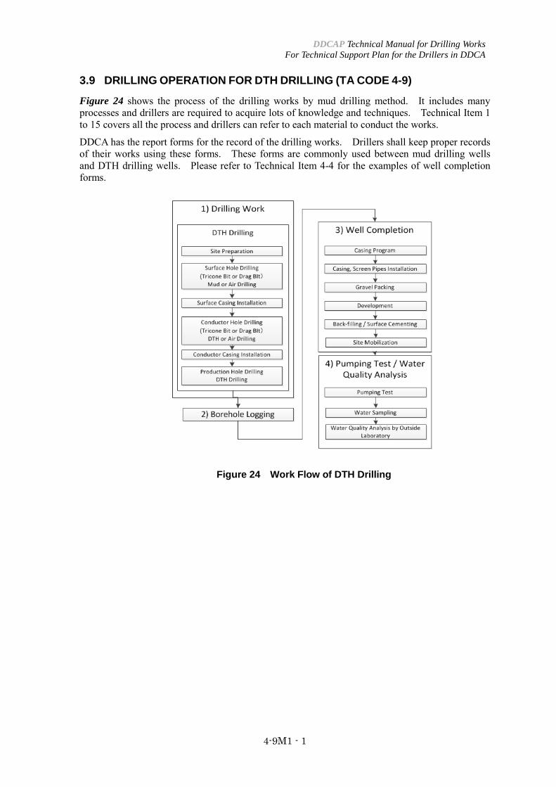
Figure 24 shows the process of the drilling works by mud drilling method. It includes many processes and drillers are required to acquire lots of knowledge and techniques. Technical Item 1 to 15 covers all the process and drillers can refer to each material to conduct the works.
DDCA has the report forms for the record of the drilling works. Drillers shall keep proper records of their works using these forms. These forms are commonly used between mud drilling wells and DTH drilling wells. Please refer to Technical Item 4-4 for the examples of well completion forms.
Figure 24 Work Flow of DTH Drilling


4-9M2 - 1
4-9M2 - 2
4-9M2 - 3

Teaching GuidanceGroundwater development and Management
Capacity Development ProjectDDCAP
1: Objectives
2. Contents
3. Teaching Methods
4. Materials
4-10
4-10 DDCA's Manual for Drilling Works
Technical Area: 4 Drilling Control
Item: 4-10 Bit control and repairing for DTH drilling
To be able to explain and advise for how to control and repair DTH bits for effective use.
- Bit control- Bit repairing
(1) Explain how to control bit numbers and check bit conditions using bit log form.(2) Explain how to recondition roller bits and blade bits using manual.

DDCAP Technical Manual for Drilling Works For Technical Support Plan for the Drillers in DDCA
4-10M1 - 1
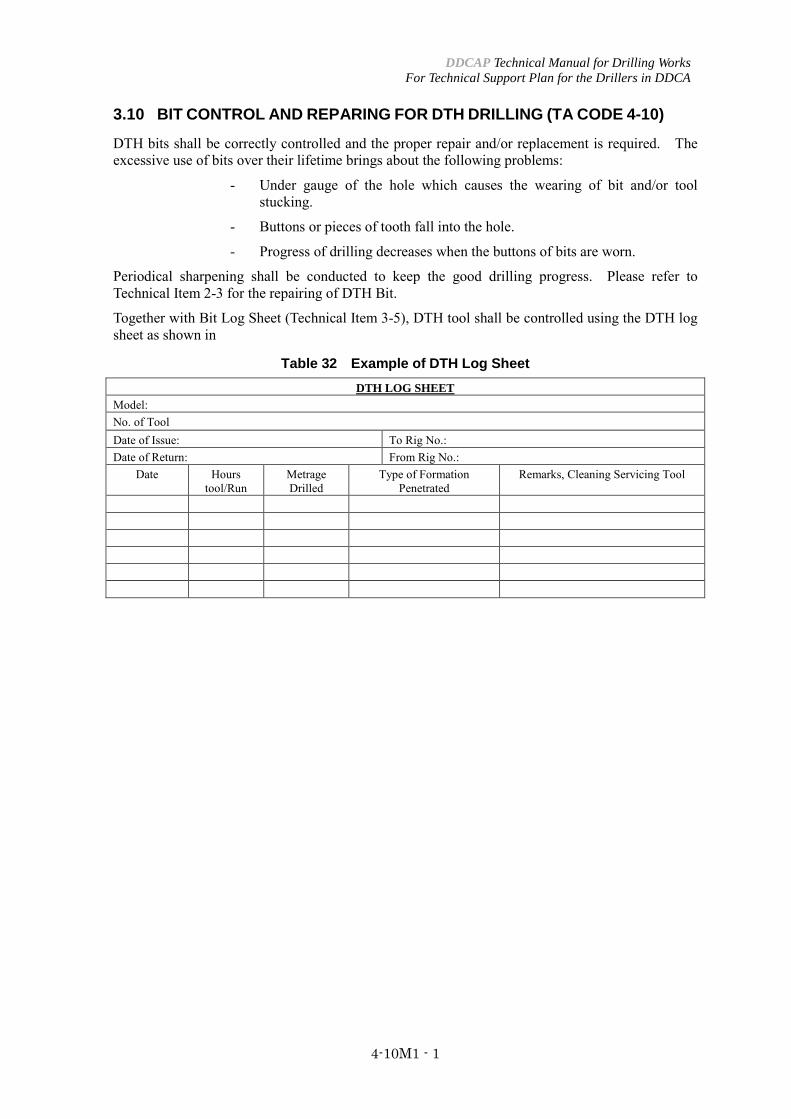
3.10 BIT CONTROL AND REPARING FOR DTH DRILLING (TA CODE 4-10)
DTH bits shall be correctly controlled and the proper repair and/or replacement is required. The excessive use of bits over their lifetime brings about the following problems:
- Under gauge of the hole which causes the wearing of bit and/or tool stucking.
- Buttons or pieces of tooth fall into the hole.
- Progress of drilling decreases when the buttons of bits are worn.
Periodical sharpening shall be conducted to keep the good drilling progress. Please refer to Technical Item 2-3 for the repairing of DTH Bit.
Together with Bit Log Sheet (Technical Item 3-5), DTH tool shall be controlled using the DTH log sheet as shown in
Table 32 Example of DTH Log Sheet DTH LOG SHEET
Model: No. of Tool Date of Issue: To Rig No.: Date of Return: From Rig No.:
Date Hours tool/Run
Metrage Drilled
Type of Formation Penetrated
Remarks, Cleaning Servicing Tool

Teaching GuidanceGroundwater development and Management
Capacity Development ProjectDDCAP
1: Objectives
2. Contents
3. Teaching Methods
4. Materials
5-1
5-1M1 DDCA's Manual for Drilling Works
Technical Area: 5 Borehole Logging
Item: 5-1 Borehole logging instruments
To be able to explain and advise for principles, measuring items and operation procedures ofborehole logging.
- Principle of borehole logging- Resistivity, SP, gamma ray- Operation of borehole logging
(1) Explain purpose of borehole logging using manual.(2) Explain meaning of resistivity, SP and gamma ray using manual.(3) Explain the operation of borehole logging instrument using manual.

DDCAP Technical Manual for Drilling Works For Technical Support Plan for the Drillers in DDCA
5-1M1 - 1
4 BOREHOLE LOGGING (TA CODE 5)
4.1 BOEREHOLE LOGGING INSTRUMENTS (TA CODE 5-1)
4.1.1 GENERAL INFORMATION ABOUT BOREHOLE LOGGING
Many of the geophysical survey methods for groundwater exploration, which are carried out on the ground-surface, can also be used within a borehole in vertical direction.
Resistivity well logs – RES Resistivity logging, usually called electric logging, provide a useful tool, and the information gained increases in general the effectiveness of the well design. A good log gives a detailed picture of the character and thickness of the various formations at the well site and an indication of the water quality by measuring the apparent resitivity of the subsurface material cross-sectioned in the borehole. Electric logging offers several important advantages, such as locating the top and bottom of each distinct layer, determining relative water quality, and differentiating fresh hard rock layers from fractured and weathered parts. A limiting factor in electric logging is that the method can only be done in boreholes that do not have casings and are filled with drilling fluid or water. The method is therefore best to be carried out in rotary mud circulation boreholes. Please note that in low-yield boreholes in hard rock formation, it is advised to carry out borehole logging the other morning after drilling was completed to allow the water level to rise for one night due to low recharge conditions.
Spontaneous Potential (SP) Logs Self-potential or spontaneous potential logs are always run in conjunction with the electric logs. Spontaneous potentials are naturally occurring electrical potentials (voltages) that result from chemical and physical changes at the contact between different types of formation material. In a borehole, potentials also occur between the drilling fluid in the borehole and the fluid in the formation and also between the drilling fluid and the filter cake on the borehole wall. As in the case of drilling DTH in Swaziland, where fluid in the borehole is the same groundwater as in the formation, there cannot be a difference in the potential of both waters (fluids). In general SP logs make only sense in boreholes filled with drilling fluid (drilling mud). To measure SP at various depths, an electrode is lowered into an uncased borehole filled with drilling fluid as one electrical terminal. The terminal of the arrangement is connected as a ground terminal at the surface, which is often placed in the mud pit. The down-hole electrode is usually negative with respect to the surface electrode. Any current in the circuit, which results from electrochemical action between the drilling fluid and the formation or formation water, is conducted to the surface through the drilling fluid column. The milli-voltmeter connected between the electrodes, therefore, measures the drop (difference) in potential in the drilling fluid column between the down-hole electrode and the surface electrode. As the down-hole electrode is moved up and down in the borehole, the meter registers variations in spontaneous potentials of the different formations. A curve showing these potentials plotted against borehole depth provides what is called the SP log. Although the SP log may indicate the permeable zones, there is no definite relationship between the magnitude of the SP deflection and the permeability and porosity of the formation. Variations shown by the SP curve are interpreted along with variations in apparent resistivity shown by the resistivity curve. The two curves together constitute what is usually called the electric log. The SP log is plotted on the left-hand of the curve sheet, where it can be compared easily with the resistivity log on the right-hand side.
DDCAP Technical Manual for Drilling Works For Technical Support Plan for the Drillers in DDCA
5-1M1 - 2
Natural Gamma Ray (GR) logs
In gamma logging, measurements are made of naturally occurring radiation coming from the materials encountered in the borehole. The record of gamma radiation is used as a qualitative guide for correlation of formations and permeability of formations.
Gamma radiation is emitted from certain elements in geologic materials that are unstable and decay spontaneously into other more stable elements. Gamma rays are similar to X-rays in that having a great ability to penetrate other materials (for example even steel casings), but gamma rays have a shorter wave length.
Certain radioactive elements occur naturally in igneous rocks (granites, gabbros) and metamorphic rocks (slate, mica-schist, gneiss) and as depositional particles in sedimentary rocks. Clays and shale contain high concentration of radioactive isotopes, usually potassium. Sands and gravel on the other hand contain primarily silica, a stable substance, and therefore emit only very low levels of radiation.
So gamma ray curves of silica rich, light colored, acidic rocks, such as granites, gneiss and sandstones are showing deflections in the curve to the left.
Gamma ray logging has a fundamental advantage over electrical logging. It can be done either in cased wells or in open boreholes containing air, water, or drilling fluid. Therefore with gamma ray it is possible logging existing wells, where logs have been lost or were not carried out. The gamma probe is very simple, having a detecting element, which is measuring the pulses given off by the radioactive materials in the different formations. The radiation extensity is expressed as the average number of counts per second (cps).
The minerals normally found in sedimentary materials such as clay, silt, sand, or sandstones contain small amounts of radioactive potassium-40, and decay products of uranium and thorium. Potassium is an important constituent of clay minerals, mica, feldspar, and shale. Quartz sand contains no potassium or radioactive potassium-40. Quartz sand formations emit gamma-rays at extremely low levels. Normally the gamma logs show more cps at depths, corresponding to clay or shale layers and few cps at depths corresponding to sand or sandstone layers, if the sand is mostly consisting from quartz.
4.1.2 OPERATION OF BOREHOLE LOGGING
Components of the equipment of the Geologger 3030: − Power winch 3895 − Geologger 3030 machine − Combination Probe (GR, SP, RES) − Sheave, sheave stand and supporting legs − 2 Batteries 12 V − 2 Surface electrodes − Power supply cords − Cable for Geologger 3030 to power winch − Cable for Geologger 3030 to sheave
Connection of the equipment: 1. Join up the components of the probe (GR + SP/RES) then seal the joint with insulation
tape
DDCAP Technical Manual for Drilling Works For Technical Support Plan for the Drillers in DDCA
5-1M1 - 3
2. Connect slowly the winch connector to the probe turning slowly until there is a click sound, and then lock the link
3. Connect the battery to the power winch 4. Sheave stand is then put over the borehole and sometimes there might be a need for the
sheave’s stand additional / support legs in case, when the temporary casing is more than 30 cm above the ground
5. Then wind the cable from the winch, while the probe lies on the ground, to the sheave wheel and the direction of the wheel will be decided by the winding of the cable. The winding of the cable should be in a cross manner and sometimes, just wind it straight. Then use the lock to prevent any slippage. Lock the probe cable with the lock knob from the wheel to avoid any slippage of the cable from the wheel and getting damaged
6. Connect the cables from power winch and sheave to connector panel of Geologger 7. Connect the earth electrodes to the connector panel and then to the ground with the
B-near (black) the borehole- and the N-30m (red) maximum away from the borehole and they should be connected to wet ground.
8. After all the connection from the connector panel has been completed and the setting of the sheave then the probe is put inside the borehole. Then connect the cable from the Geologger to another battery.
Operation of the equipment:
Set the probe into the borehole and knowing the casing top above ground level, you will know exactly the top of the spring of the probe would set level with ground level.
Set the power switch “ON” and the menu will be displayed at the LCD display. As the menu items are displayed, they will respond to function keys shown to the left of the menu, F1 to F4.
First step
For the display and the setting of date and time, observe the following procedures: − Choose date and time by pressing F1 − Setting the date by pressing the key (*) star. This enables you to set the date, “YY MM
DD”, by putting in the figures from the keyboard. − Set the time by pressing the hash key (#). This enables you to set the time, “ HH MM SS”,
by putting in the figures from the keyboard. Then enter.
Second step: − Choose system by pressing F4 − System check by pressing F1
This enables the machine to check that everything is functioning well and if it is in order. It will let you know in case, which part of the system is not ok.
Note: If there is an error, for example with the floppy disk drive, it will tell you where the error is, and all you have to do, is to check, if the floppy disk is inside and then slightly press or move it sideways. Then cancel and restart system check.
Third step: − Choose measure by pressing F3 − Measure by pressing F1
DDCAP Technical Manual for Drilling Works For Technical Support Plan for the Drillers in DDCA
5-1M1 - 4
Depth input will appear, and then change depth to zero and then press enter. Sign change due to the direction of probe movement from sheave by pressing F1, if necessary – then press enter. − Then set the gamma range, which is normally 0. 2K cps by pressing F3 – then press enter − The ampere range is automatically set. − Input sampling interval is normally every 10 cm, but can be change to other measuring
interval. − On the display will appear >>Reset data & start. Just press enter. − After measuring press the enter key. − Enter ID No. of the borehole. Then enter. − Print out click play back on F2 − Input of ID No. This helps to know the file, in which the recorded data are stored on the
floppy disk. This is entered with three figures e. g. M2-10-2, ID No. is 001 when measuring down and 002 when measuring up. With more reference to the recorded data, there is a sheet that needs to be filled for ID No. and borehole No.
− Depth scale selection is normally 1/500, but select by pressing F4. − Selection of gamma scale can be selected from the keyboard from 1 to 9. − Selection of resistivity scale can be selected from the keyboard from 1 to 9. − Selection of Spontaneous Potential (SP) scale can be selected from keyboard from 1 to 5.
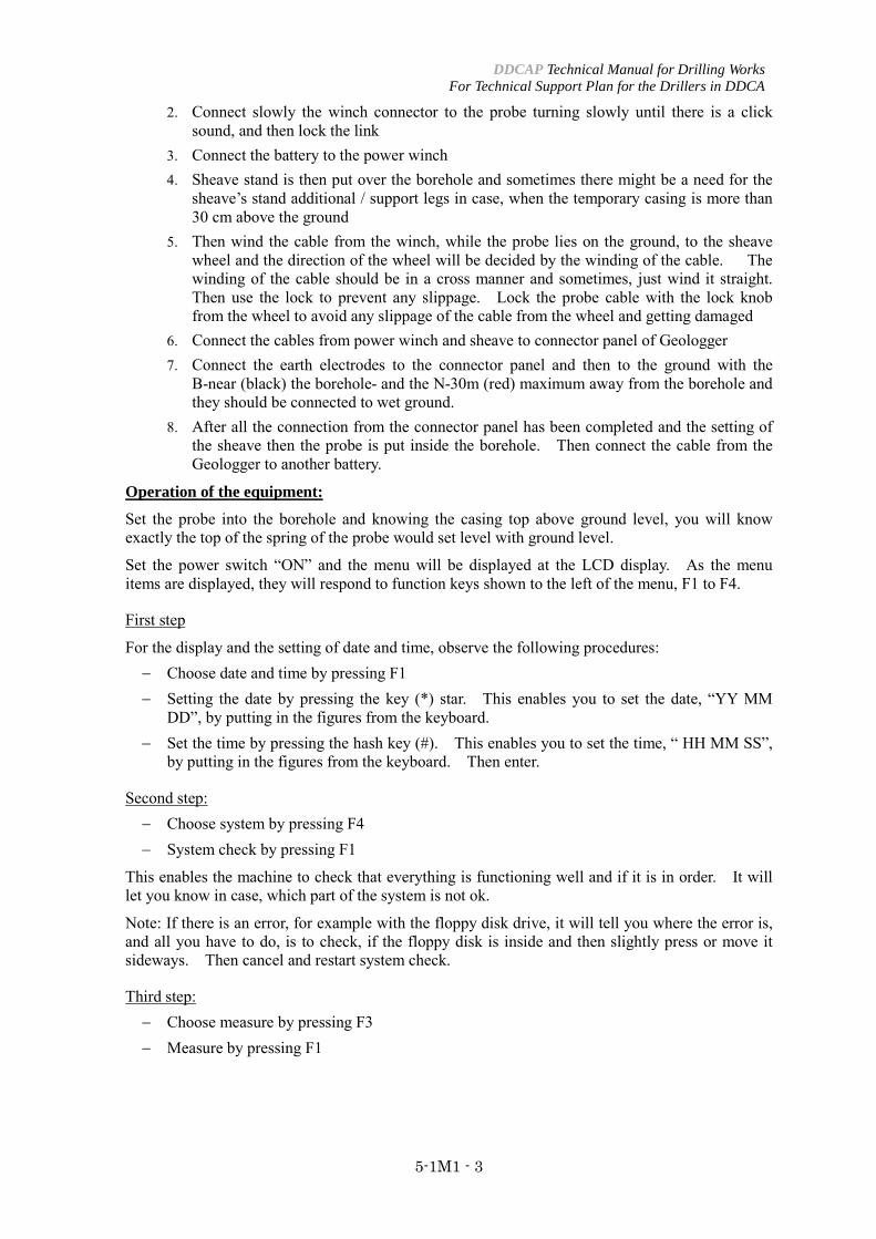
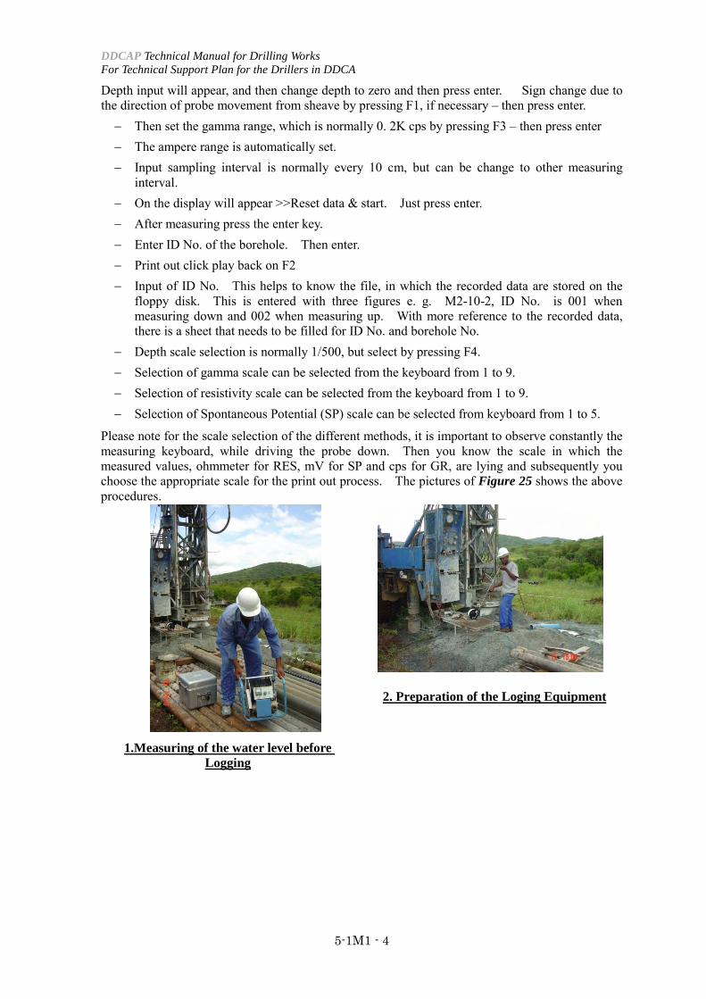
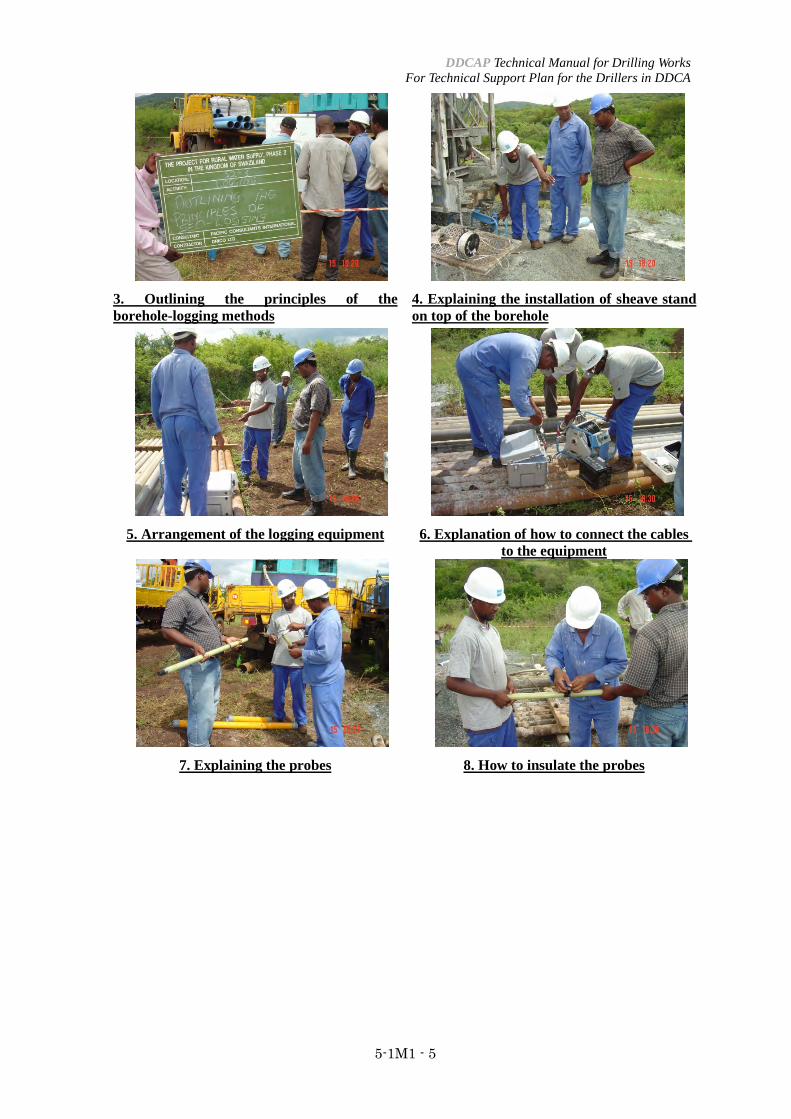
Please note for the scale selection of the different methods, it is important to observe constantly the measuring keyboard, while driving the probe down. Then you know the scale in which the measured values, ohmmeter for RES, mV for SP and cps for GR, are lying and subsequently you choose the appropriate scale for the print out process. The pictures of Figure 25 shows the above procedures.
1.Measuring of the water level before Logging
2. Preparation of the Loging Equipment
DDCAP Technical Manual for Drilling Works For Technical Support Plan for the Drillers in DDCA
5-1M1 - 5
3. Outlining the principles of the borehole-logging methods
4. Explaining the installation of sheave stand on top of the borehole
5. Arrangement of the logging equipment 6. Explanation of how to connect the cables to the equipment
7. Explaining the probes 8. How to insulate the probes
DDCAP Technical Manual for Drilling Works For Technical Support Plan for the Drillers in DDCA
5-1M1 - 6
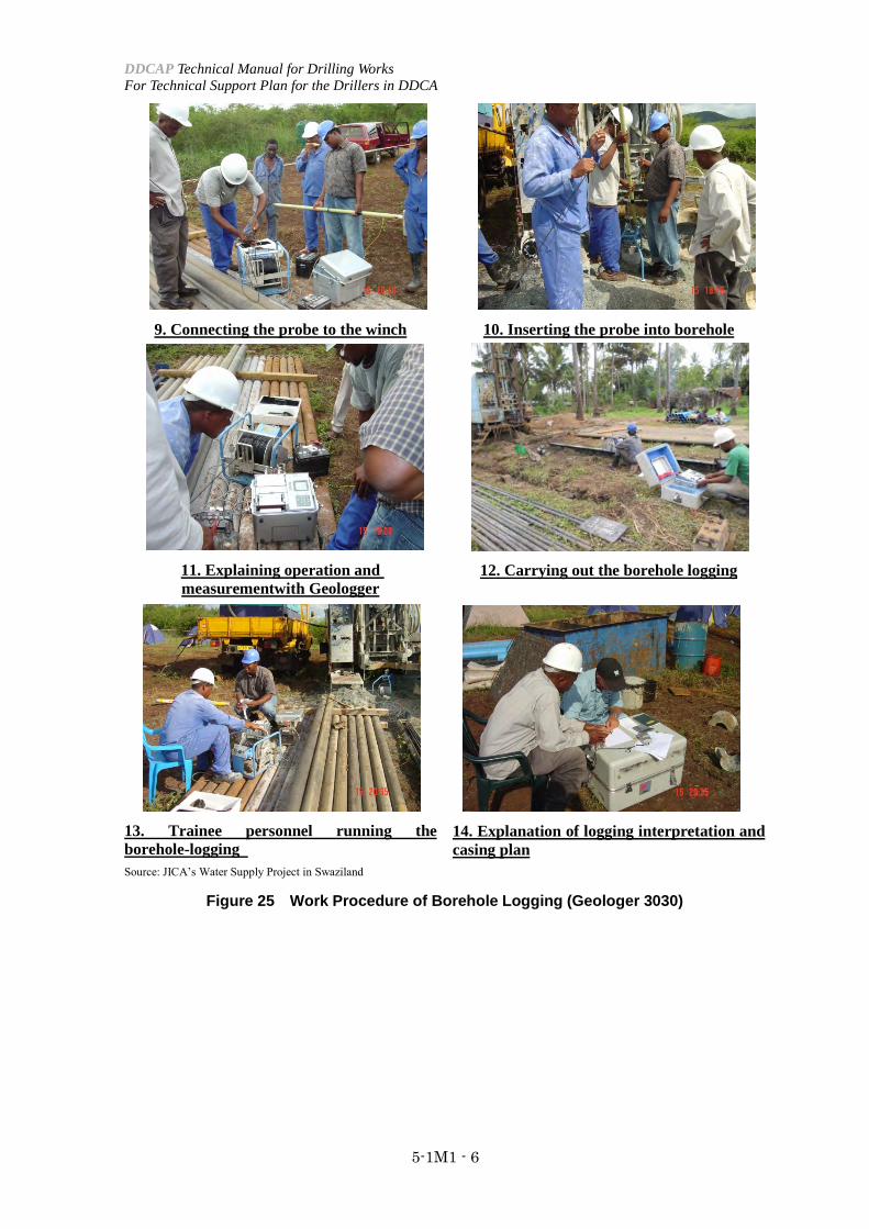
9. Connecting the probe to the winch 10. Inserting the probe into borehole
11. Explaining operation and measurementwith Geologger
12. Carrying out the borehole logging
13. Trainee personnel running the borehole-logging
14. Explanation of logging interpretation and casing plan
Source: JICA’s Water Supply Project in Swaziland
Figure 25 Work Procedure of Borehole Logging (Geologer 3030)
Teaching GuidanceGroundwater development and Management
Capacity Development ProjectDDCAP
1: Objectives
2. Contents
3. Teaching Methods
4. Materials
5-2
5-2M1 DDCA's Manual for Drilling Works
Technical Area: 5 Borehole Logging
Item: 5-2 Interpretation of borehole logging results
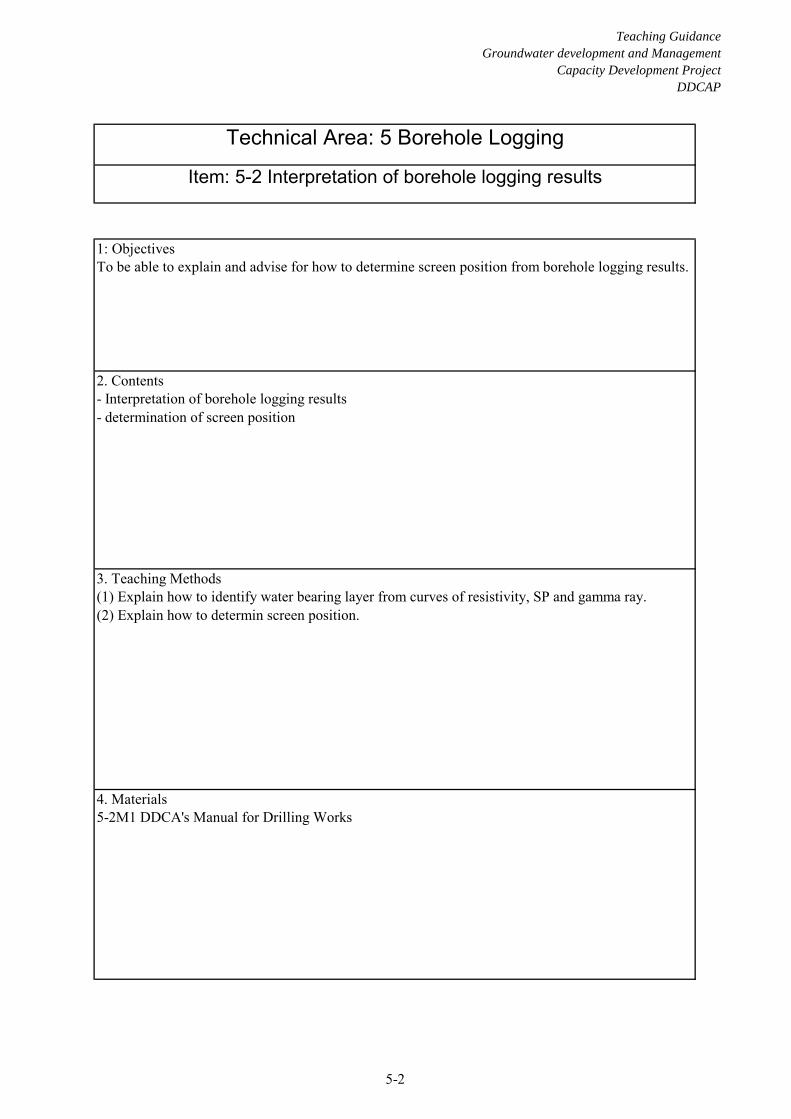
To be able to explain and advise for how to determine screen position from borehole logging results.
- Interpretation of borehole logging results- determination of screen position
(1) Explain how to identify water bearing layer from curves of resistivity, SP and gamma ray.(2) Explain how to determin screen position.

DDCAP Technical Manual for Drilling Works For Technical Support Plan for the Drillers in DDCA
5-2M1 - 1
4.2 INTERPRETATION OF BOREHOLE LOGGING RESULTS (TA CODE 5-2)
4.2.1 INTERPRETATION OF BOREHOLE LOGGING RESULTS
Interpretation of electric logs The electric log cannot be used to qualitatively identify the material encountered in the borehole, because the measured resitivity is a function of various different parameters, such as composition of the drilling mud or the fluid in the borehole, fluids in the formation, diameter of the borehole and the distance of the electrodes within the measuring probe. Depth related rock samples recovered during the drilling (drilling cuttings) are required for positive identification of specific geological formations. Dry formations are poor electrical conductors and show very high resistivities as well as fresh and dense igneous, metamorphic and volcanic rocks, such as granites, granodiorites, amphibolites, gneiss, dolerites, basalts and ryolites. Saturation of a formation reduces its resistivity. The reduction again is partly controlled by the porosity of the formation. The type of material is only factor, which is influencing the resistivity. Water in the pore space is always mineralized differently due to the material of the formation and it’s chemical composition. So various different factors are influencing the resistivity and experience is an important factor in the interpretation of electric logs. Knowledge of the general trends and the spectrum described above are also very important. In the hard rock formation of Swaziland high resistivities are usually indicating dense and dry hard rock types, whereas curves changing to lower resistivity values are indicating fractures and fissures and weathered formations, which can be filled with groundwater.
Interpretation of SP logs Interpreting SP logs is generally very difficult and it makes only sense to analyze logs which were carried out in an uncased borehole filled with drilling fluid and in a borehole having distinctive clay layers to provide a so called baseline (clay line). Please note here that SP logs published from oil-field works are completely different from SP logs run in water-wells. It is important to understand the differences between oil-well and water-well SP curves. In general groundwater associated with oil is salt water. The electrical conductivity of this water is extremely high in comparison with the conductivity of the water in the drilling fluid. Groundwater suitable for drinking water purposes has low dissolved solids, on the other hand, and therefore has a much lower conductivity than oil-field brine. Its electrical conductivity may be about the same as, or even less than, the conductivity of water in the drilling fluid. Thus, the electrochemical reaction between the formation water and the drilling fluid is quite different, depending on whether the formation water is considerably more salty than the drilling fluid (oil-field condition), or whether the formation water has about the same salinity as the drilling fluid (water-well condition). When a permeable formation (aquifer) contains salt water and the drilling fluid is made with fresh water, the SP normally shows a relatively large deflection to the left in relation to the clay baseline. The SP deflection opposite the same formation containing fresh water, however, would be relatively small. Another way to describe the difference is to note that the formation with salt water shows a high negative potential in relation to clay layers, whereas the formation with fresh water shows only a slight negative potential. Some helpful observations in interpreting SP logs for formation with fresh water: − It is often difficult to interpret a SP curve at shallow depth. SP deflections are more
pronounced in moderately deeper to deeper wells because, as depth increases, the ground-water tends to become more highly mineralized.
− The first step in interpretation is to establish a clay baseline (shale baseline) on the log. If clay layers are not present, the SP log add little information to the interpretation. For many wells, the SP curve may be of little value, because variations in the curve may be
DDCAP Technical Manual for Drilling Works For Technical Support Plan for the Drillers in DDCA
5-2M1 - 2
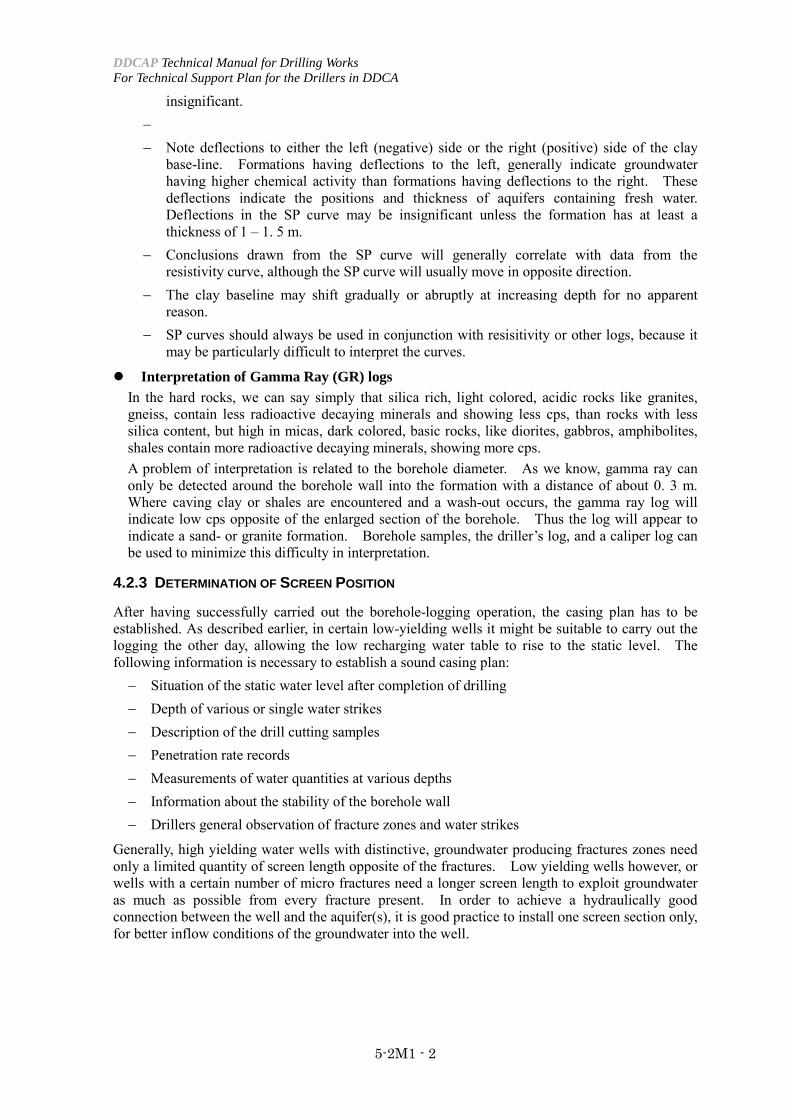
insignificant. − − Note deflections to either the left (negative) side or the right (positive) side of the clay
base-line. Formations having deflections to the left, generally indicate groundwater having higher chemical activity than formations having deflections to the right. These deflections indicate the positions and thickness of aquifers containing fresh water. Deflections in the SP curve may be insignificant unless the formation has at least a thickness of 1 – 1. 5 m.
− Conclusions drawn from the SP curve will generally correlate with data from the resistivity curve, although the SP curve will usually move in opposite direction.
− The clay baseline may shift gradually or abruptly at increasing depth for no apparent reason.
− SP curves should always be used in conjunction with resisitivity or other logs, because it may be particularly difficult to interpret the curves.
Interpretation of Gamma Ray (GR) logs In the hard rocks, we can say simply that silica rich, light colored, acidic rocks like granites, gneiss, contain less radioactive decaying minerals and showing less cps, than rocks with less silica content, but high in micas, dark colored, basic rocks, like diorites, gabbros, amphibolites, shales contain more radioactive decaying minerals, showing more cps. A problem of interpretation is related to the borehole diameter. As we know, gamma ray can only be detected around the borehole wall into the formation with a distance of about 0. 3 m. Where caving clay or shales are encountered and a wash-out occurs, the gamma ray log will indicate low cps opposite of the enlarged section of the borehole. Thus the log will appear to indicate a sand- or granite formation. Borehole samples, the driller’s log, and a caliper log can be used to minimize this difficulty in interpretation.
4.2.3 DETERMINATION OF SCREEN POSITION
After having successfully carried out the borehole-logging operation, the casing plan has to be established. As described earlier, in certain low-yielding wells it might be suitable to carry out the logging the other day, allowing the low recharging water table to rise to the static level. The following information is necessary to establish a sound casing plan: − Situation of the static water level after completion of drilling − Depth of various or single water strikes − Description of the drill cutting samples − Penetration rate records − Measurements of water quantities at various depths − Information about the stability of the borehole wall − Drillers general observation of fracture zones and water strikes
Generally, high yielding water wells with distinctive, groundwater producing fractures zones need only a limited quantity of screen length opposite of the fractures. Low yielding wells however, or wells with a certain number of micro fractures need a longer screen length to exploit groundwater as much as possible from every fracture present. In order to achieve a hydraulically good connection between the well and the aquifer(s), it is good practice to install one screen section only, for better inflow conditions of the groundwater into the well.
DDCAP Technical Manual for Drilling Works For Technical Support Plan for the Drillers in DDCA
5-2M1 - 3
For a more safe installation of the well assembly into the well, it is common practice to drill some 1-3% deeper than the depth, at which it is intended to place the bottom cap of the casings. The following pipe-lengths are available to install within the project: − Plain casing length of 5.72 m − Plain casing length of 2.81 m − Plain casing length of 0.93 m − Plain screen length of 2.81 m
The depth calculation of the casings and screens to be installed into the borehole should start from the bottom to the top of the borehole, indicating as well the portion of casings, which is going to stand over the ground surface. Knowing from the records the height of the drilling table of the drilling rig above ground surface, it is possible to indicate exactly the casing depth.
Screens need to be placed opposite of groundwater bearing zones (aquifers) and not shallower than the first water strike, which was reported during drilling. The project is not allowing the installation of screens at a shallower depth than 20 m below ground surface.
Generally on top of the bottom cap (lowest part of the well) a so called sedimentation pipe or sump pipe has to be installed, being a plain casing pipe with 2.81 m length.
Centralizers have to be installed around casing and screens in the depth where gravel pack is intended to be placed, in order to keep the pipes centrically in the borehole and allowing the gravel pack to be placed evenly around the screen pipes.
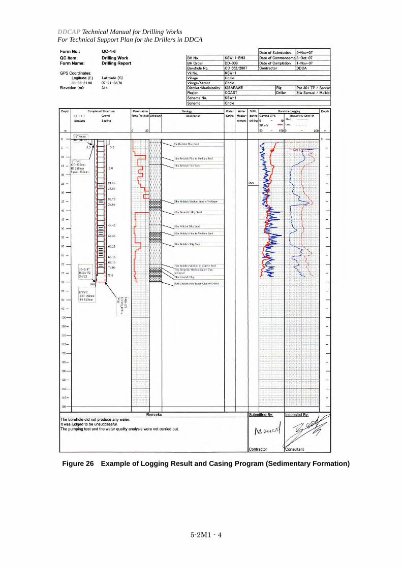
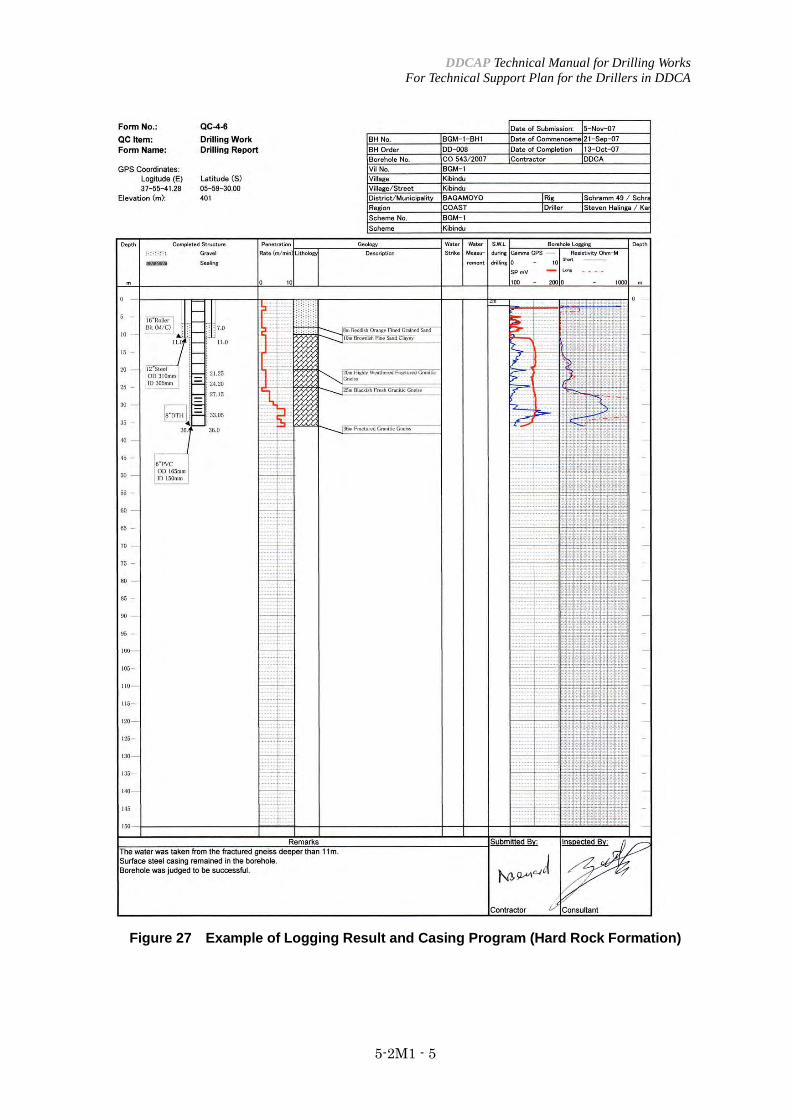
Figure 26 shows the example of logging results and casing program for a borehole in sedimentary formation in Kisarawe region. Figure 27 shows the one for a borehole in hard rock formation in Bagamoyo region. Principally, resistivity shows the high value at the position of the aquifer in sedimentary formation. On the contrary the resistivity of the aquifer in hard rock formation becomes higher than the formation with lower water contents.
DDCAP Technical Manual for Drilling Works For Technical Support Plan for the Drillers in DDCA
5-2M1 - 4
Figure 26 Example of Logging Result and Casing Program (Sedimentary Formation)
DDCAP Technical Manual for Drilling Works For Technical Support Plan for the Drillers in DDCA
5-2M1 - 5
Figure 27 Example of Logging Result and Casing Program (Hard Rock Formation)