Embed Size (px)
Citation preview
www.eao.com
Technical Article
Design Considerations for Effective Human Machine Interface Systems
The task of an HMI System is to make the function of a technology self-evident to the user. A well-designed HMI fits the user’s image of the task he or she will perform. The effectiveness of the HMI can affect the acceptance of the entire system; in fact in many applications it can impact the overall success or failure of a product. The HMI System is judged by its usability, which includes how easy it is to learn as well as how productive the user can be.
An HMI System performs the functions that the user requires to carry out the prescribed task with a minimum of expended effort while improving productivity. Finally, it needs to perform to the user’s satisfaction. It is the task of everyone involved in the HMI design, the engineers, management, HMI consultant, and industrial designer, to meet the
defined usability requirements for a specific HMI System.
A well-designed HMI System does more than just present control functions and information; it provides an operator with active functions to perform, feedback on the results of those actions, and information on the system’s performance.
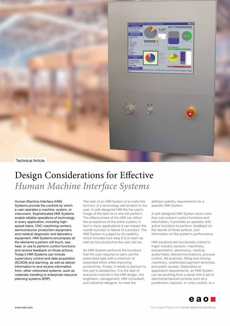
HMI solutions are functionally critical to major industry sectors—machinery, transportation, electronics, medical, audio/video, telecommunications, process control, life sciences, lifting and moving machinery, unattended payment terminals, and public access. Depending on application requirements, an HMI System can be anything from a panel with a set of electromechanical controls such as a pushbutton, keylock, or rotary switch, to a
Human Machine Interface (HMI) Systems provide the controls by which a user operates a machine, system, or instrument. Sophisticated HMI Systems enable reliable operations of technology in every application, including high-speed trains, CNC machining centers, semiconductor production equipment, and medical diagnostic and laboratory equipment. HMI Systems encompass all the elements a person will touch, see, hear, or use to perform control functions and receive feedback on those actions. Today’s HMI Systems can include supervisory control and data acquisition (SCADA) and alarming, as well as deliver information to and receive information from, other networked systems, such as materials-handling or enterprise-resource planning systems (ERP).
www.eao.com . 2www.eao.com . 2
A poor HMI System can alienate users or potential customers, encourage users to circumnavigate the system. As the direct link to the user, HMIs directly represent the core system’s quality and value.
“A sophisticated mix of design and layout considerations, such as contemporary style, colour, and tactile response coupled with ergonomic and intuitive operation, create an optimal user experience that determines a customer’s satisfaction with the core product.”
“Not every HMI would benefit from a capacitive iPhone-like interface.”
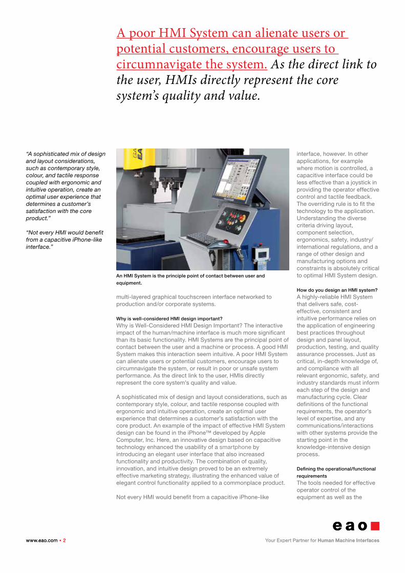
multi-layered graphical touchscreen interface networked to production and/or corporate systems.
Why is well-considered HMI design important?
Why is Well-Considered HMI Design Important? The interactive impact of the human/machine interface is much more significant than its basic functionality. HMI Systems are the principal point of contact between the user and a machine or process. A good HMI System makes this interaction seem intuitive. A poor HMI System can alienate users or potential customers, encourage users to circumnavigate the system, or result in poor or unsafe system performance. As the direct link to the user, HMIs directly represent the core system’s quality and value.
A sophisticated mix of design and layout considerations, such as contemporary style, colour, and tactile response coupled with ergonomic and intuitive operation, create an optimal user experience that determines a customer’s satisfaction with the core product. An example of the impact of effective HMI System design can be found in the iPhone™ developed by Apple Computer, Inc. Here, an innovative design based on capacitive technology enhanced the usability of a smartphone by introducing an elegant user interface that also increased functionality and productivity. The combination of quality, innovation, and intuitive design proved to be an extremely effective marketing strategy, illustrating the enhanced value of elegant control functionality applied to a commonplace product.
Not every HMI would benefit from a capacitive iPhone-like
interface, however. In other applications, for example where motion is controlled, a capacitive interface could be less effective than a joystick in providing the operator effective control and tactile feedback. The overriding rule is to fit the technology to the application. Understanding the diverse criteria driving layout, component selection, ergonomics, safety, industry/ international regulations, and a range of other design and manufacturing options and constraints is absolutely critical to optimal HMI System design.
How do you design an HMI system?
A highly-reliable HMI System that delivers safe, cost-effective, consistent and intuitive performance relies on the application of engineering best practices throughout design and panel layout, production, testing, and quality assurance processes. Just as critical, in-depth knowledge of, and compliance with all relevant ergonomic, safety, and industry standards must inform each step of the design and manufacturing cycle. Clear definitions of the functional requirements, the operator’s level of expertise, and any communications/interactions with other systems provide the starting point in the knowledge-intensive design process.
Defining the operational/functional
requirements
The tools needed for effective operator control of the equipment as well as the
An HMI System is the principle point of contact between user and
equipment.
www.eao.com . 3www.eao.com . 3
Touchscreens are not a good choice in environments where oil, condensation, or airborne debris can collect on flat surfaces.Defining input requirements will help decide which control technology is best suited for an application.
“A thorough knowledge of technical ergonomic, design, and manufacturing standards is fundamental to HMI System design.”
“Feedback—visual, auditory, tactile, or any combination—is essential in systems that have no mechanical travel, such as a touchscreen or a capacitive device that when triggered has no moving parts.”
requirements of the overall application determine the selection of interface functions. There are many factors to consider in the initial design phase that are critical to both the HMI and the core system to which it is interfaced. Besides industry and functional requirements, selection priorities also depend upon the experience level of the operator and environment, among many other factors. The driving priority might tilt toward ergonomics for example, as is the case for applications subject to ADA (Americans with Disabilities Act) Guidelines. On the other hand, production floor applications are typically robust and strictly functional, driven by the need to withstand a harsh environment. In the transportation industry, for example, consistency with a previous design – to provide a consistent operator environment – is very often the ruling priority.
General functionality
How many functions will be controlled by this interface? Where a single function might be served by pushbutton, keylock, and rotary switches, multiple functions could require several screen displays to cover operator functions and options. What kind of visual, auditory, or tactile feedback will best serve the operator in performing the defined functions?
Does the operation require real-time indicators?
Multiple data-entry points? How many times is a button pressed? Are there safety considerations? Are emergency stop switches required? Which standards apply – industry, safety, international? The goal is to provide an HMI System that clearly communicates the information necessary to accomplish the specific task
assigned to the defined component, system, or equipment.
Degree of input complexity
Input can be as simple as an on/ off switch or a touchscreen display. Touchscreen HMI Systems are increasingly popular in public transaction applications, because they can simplify complex operations, and tolerate a moderate degree of rough use. They are also used in clean production environments, for example, in the semiconductor industry, where they are often interfaced to machines that perform many different sets of processes. Touchscreens are not a good choice in environments where oil, condensation, or airborne debris can collect on flat surfaces. Defining input requirements will help decide which control technology is best suited for a specific application.
Operator feedback
Feedback is critical to operator effectiveness and efficiency. Feedback can be visual, auditory, tactile, or any combination necessary for the application. Feedback is essential in systems that have no mechanical travel, such as a touchscreen or a capacitive device that when triggered has no moving parts. In some cases feedback provides confirmation of an action, while in others it adds to the functionality.
Interfaces/Interconnection
HMI Systems must be able to
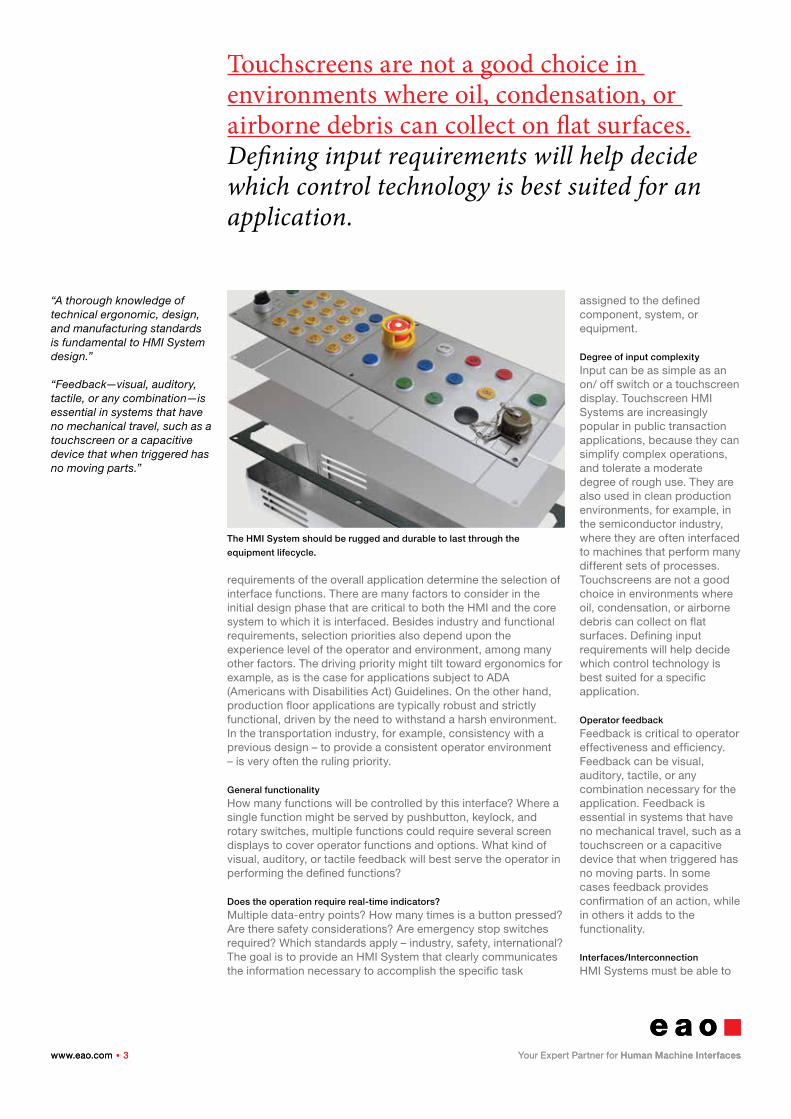
The HMI System should be rugged and durable to last through the
equipment lifecycle.
www.eao.com . 4www.eao.com . 4
A product is as good as its weakest link. If the HMI System fails, it is most often perceived as a failure of the core system itself.
“HMI System style is a high priority for many consumer goods and especially luxury products.”
“HMI style considerations are effective when they create a level of product differentiation that reinforces the USP.”
interface/ interconnect with the system under control as well as other related systems. For example, in an industrial setting the HMI might connect via hardwire or a serial bus to I/O points that provide machine status. Additionally, it might be networked to a manufacturing execution system and a supply logistics/inventory system. In an ATM application, for example, the HMI interface securely connects to the bank’s financial systems.
Environmental considerations
The application environment – encompassing both physical location and vertical industry environment – determines HMI System durability requirements. Environmental stresses include exposure to moisture and the elements, temperature extremes, wear and tear, vandalism, and general rough use characteristic of harsh environments such as an industrial production floor. For exterior use, consideration also must be given to the effects of prolonged exposure to UV radiation. In addition a display might need to work in a high ambient light environment.
Life-cycle durability
Not only should the HMI System be rugged enough to withstand the elements and heavy use, but it should also last for the duration of the equipment lifecycle. For example, a Magnetic Resonance Imaging (MRI) HMI System interface should last at least 10 years, while a kiosk for public use could have a shorter lifecycle due to a more dynamic environment eager to adopt the latest in HMI technology, or just the fact that the Return-On-Investment for a kiosk is shorter and the replacement cycle faster. A product is as good as its weakest link. If the HMI System fails,
it is most often perceived as a failure of the core system itself. Therefore the operator interface should be designed to an even higher level of reliability, because it is the critical link between the operator and the equipment. An operator or customer’s perception of the interface – particularly if it is a highly reliable and intuitive interface, with good styling, tactile response, etc. – extends to the user’s appreciation of the equipment itself.
Style
HMI System style is a high priority for many consumer goods and especially luxury products. In the marine industry, the consoles for high-performance racing boats feature contemporary styling and an array of ergonomic technologies. Such as responsive tactile feel and colour illumination in support of the confirmation of quality and luxury befitting a product commanding a high end price point. HMI style considerations are effective when they create a level of product differentiation that delivers a unique selling proposition.
Regulatory/standards
considerations
A thorough knowledge of technical ergonomic, design, and manufacturing standards is fundamental to HMI System design. These include engineering standards, such as MIL-STD-1472F, which establishes human engineering design criteria for military
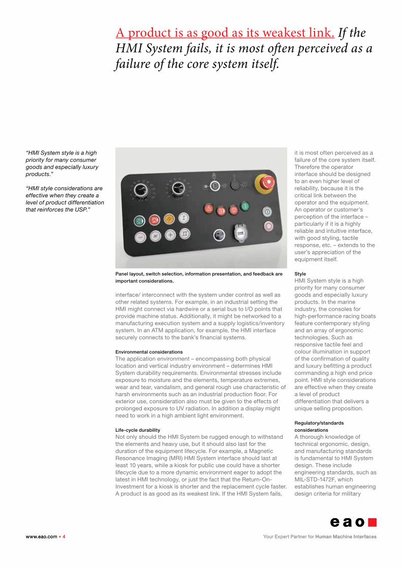
Panel layout, switch selection, information presentation, and feedback are
important considerations.
www.eao.com . 5www.eao.com . 5
Know your operators. The key to a successful HMI System implementation requires a well-grounded definition and understanding of the operators.
“International standards may affect the placement of components, legend size and colour, emergency stop switch configuration and guards, and other ergonomic factors that improve usability, efficiency, and safety.”
“Typically there are three general categories of users: operators, supervisors, and maintenance personnel.”
systems, subsystems, equipment, and facilities; federal standards set by the Americans With Disabilities Act; and industry guidelines such as those from SEMI S2-93, the global semiconductor industry association, covering HMI for semiconductor manufacturing equipment. Additional HMI specifications are defined by ANSI, IEEE, ISO, and others.
Depending on the ultimate product application, observing appropriate standards assures that a product will meet industry criteria. Standards govern placement of components, legend size and colour, emergency stop switch configuration and guards, and other ergonomic factors that improve usability, efficiency, and safety.
Define the operator
Know your operators – the key to a successful HMI System implementation requires a well-grounded definition and understanding of the operators. Will the operator be a passive/intuitive user? If so, commands/functions should be simple with an easy-to-comprehend interface. For this type of user, repeatability is also important – information and actions should appear consistently from use to use. For an expert user, where more sophisticated control is desirable, there may be multiple layers or levels for interfacing with equipment. Typically there are three general categories of users (whether they are novices or experts): operators, supervisors, and maintenance personnel.
Operators
The primary concern is providing the operator with intuitive
access to the subset of controls necessary for daily production tasks on the equipment. In general, the idea is to minimize unnecessary data while keeping detailed data available upon request. Changing parameters is typically restricted to prevent potential errors or experimentation. The controls should allow an operator to make intelligent decisions but limit the potential for error or improper control settings.
Supervisors
A higher level of control is generally granted to supervisors and access may be controlled by a password/log-in procedure. This may include separate screens of detailed information and offer more data entry options.
Maintenance
Maintenance personnel can be given full access to machine control and data displays. These capabilities are often inaccessible by operators and supervisors. For any user along the range from intuitive to expert, interface ergonomic considerations should include: panel layout, HMI component selection, information presentation, feedback, and safety considerations.
Panel layout
The panel layout should be designed to provide the operator functional groups of related information in a predictable and consistent manner. In addition, the system must require an operator to
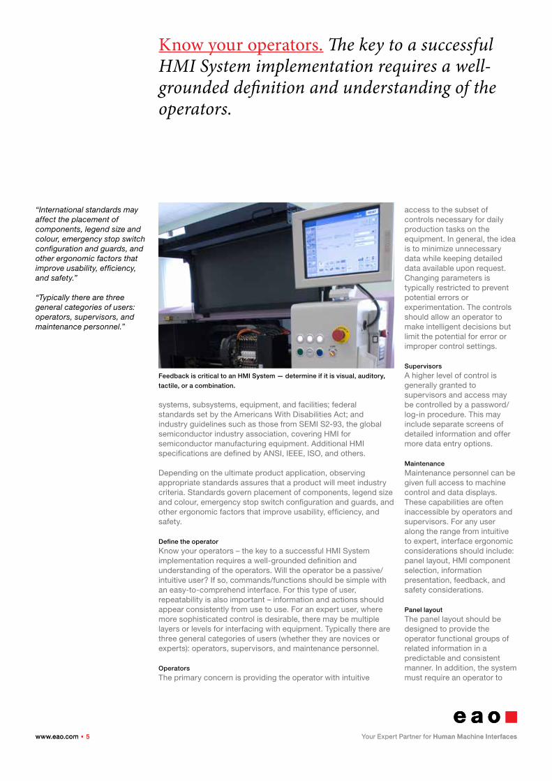
Feedback is critical to an HMI System — determine if it is visual, auditory,
tactile, or a combination.
www.eao.com . 6www.eao.com . 6
Simplicity is the key so don’t crowd a screen. Cluttering it with irrelevant data will force an operator to search for the required information, which increases response time and potential errors.
“The HMI designer needs to select the appropriate control technologies as well as switches and components to suit the application.”
“The panel layout should minimize the need for the operator to change positions, present the controls according to their expected order of use, and group related controls together.”
initiate action and keep the operator informed by providing timely feedback on those actions. The layout should be organized so that the operator is clearly prompted in advance when the next operator action is required.
The HMI designer needs to select the appropriate control technologies as well as switches and components to suit the application. In general, any displays should be located close to the controls that affect them. The panel layout should minimize the need for the operator to change positions, present the controls according to their expected order of use, and group related controls together. Emergency-stop and related safety-critical controls need to be clearly identified and typically require two distinct actions to activate – for example, a push and twist, or push and pull for release. Controls should also allow fast recovery from error.
HMI component selection
HMI designers can simplify their search for the appropriate switch or HMI component by carefully analysing their application requirements then determining the following: � Electrical ratings � Actuation preferences (momentary, maintained, rotary, etc.) � Physical configuration and mounting needs � Special requirements such as illumination, marking, environmental sealing, etc.
Colour scheme
The key to effective use of colour is simplicity. Avoid too many
colours or flashing alarms. Stick with the “traffic light” model for key actions: � Red for stop/failure/fault � Yellow for warning � Green for OK/start/go/pass
Keep colours bold and bright and use a neutral background if necessary to make them stand out. Use colours conservatively, conventionally, and consistently. Colour should never be the sole source of information. HMI illumination technology can integrate the use of multiple indication colours using widely available RGB LEDs. The LEDs can generate each primary colour but also blend colours to create an unlimited number of indication choices. This colour generation capability provides an HMI designer with the ability for multiple uses of a single discrete switch for multiple functions via a combination of software sequence and colour creation.
Information presentation
Once again, simplicity is the key. Don’t crowd a screen – avoid cluttering it with irrelevant data. Forcing an operator to search for the required information increases response time and potential errors. Have a consistent set of menu buttons and functions from screen to screen. If you have multiple screens of information, make the operator’s progress through them intuitive and logical. Always provide a clear way back. Whenever appropriate, provide information graphically
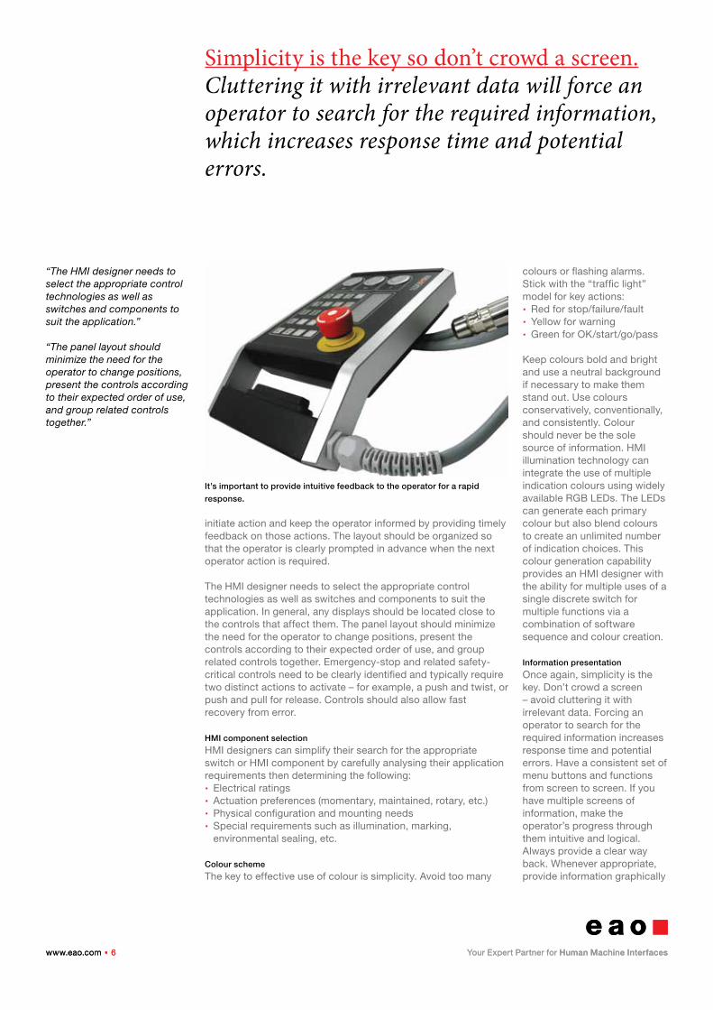
It’s important to provide intuitive feedback to the operator for a rapid
response.
www.eao.com . 7www.eao.com . 7
If there are alarms, give them a clear meaning and provide error reporting. The operator should be informed in plain language that an error has occurred and if possible, given guidance on how to solve it or whom to contact.
“If you have multiple screens of information, make the opera-tor’s progress through them intuitive and logical.”
“Once you have defined HMI functionality, you are ready to investigate control technolo-gies. Each technology has advantages and disadvantages related to the HMI System, equipment, and application.”
– use meters or moving bars – rather than alphanumeric indicators. Line up numeric values and clearly label with units. Keep fonts to a minimum, use upper and lower case (more legible), and use dark fonts on a light background at a size that is easily readable. To indicate changing states, use changing icons. Once again, don’t rely solely on colour to indicate important information – provide clear labels. If there are alarms, give them a clear meaning and provide error reporting. The operator should be informed in plain language that an error has occurred and if possible, given guidance on how to solve it or whom to contact. Help files should be easily accessed. Don’t use acronyms unless all potential users clearly understand their meanings. Provide support for multiple language implementation.
User feedback
Feedback is critical to ergonomic industrial design. Make sure the results of pressing a control button, toggling a switch, or entering a command are absolutely clear. Determine if operator feedback is visual, auditory, tactile, or a combination of multiple techniques. Illumination of multicoloured LEDs, illumination of different switches or switch positions, on-screen highlights, flashing lights or icons – can each provide important feedback to the operator such as system status, confirmation of an operation, or fault/ alarm. HMI display technology can also use multicoloured illumination to distinguish various functions and processes performed by multi-operational equipment.
Be consistent in your approach to illumination. If a switch with halo illumination indicates standby in one instance, don’t use it to indicate a different process status, unless a change of halo
colour is generated. Feedback response signals can also be audible or tactile, such as a mechanical click or snap, or a tactile haptic response or vibration. The feedback could also represent a pre-emptive warning. Here familiar symbolic colours serve effectively, for example, red signifies a fault condition and green indicates the satisfactory completion of a process. In the computer industry, blue is used to indicate that it is safe to perform a service function, for example to remove a piece of hardware while a system is running.
It is most important that the whole feedback function feels intuitive to the operator, encouraging a rapid and intuitive response supporting optimal operator performance and also customer satisfaction. Differentiate between data entry points and status indication so that an operator can distinguish between what can be changed and what is being reported at a glance.
Once you have defined HMI functionality, you are ready to investigate control technologies. Each technology has advantages and disadvantages related to the HMI System, equipment, and application.
Cursor Control
(Trackball, joystick, keypad, touchpad, etc.) The selection between different control technologies is primarily determined by the resolution of
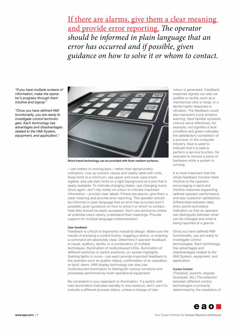
Short-travel technology can be provided with flush resilient surfaces.
www.eao.com . 8www.eao.com . 8
Be consistent in your approach to illumination. If a switch with halo illumination indicates standby in one instance, don’t use it to indicate a different process status, unless a change of halo colour is generated.
“Pushbutton switches allow the option of illumination to indicate open/close switch status when a quick visual indication is desired.”
“Rotary switches also can be used for an application requiring multiple positions – up to 12 indexed stops with highly complex contact configurations.”
control that is required by the application. For example, a medical device used to outline a patient’s tumor – in order to obliterate or radiate the area without inflicting collateral damage – requires the finest degree of control achievable. A trackball or joystick enables granular, pixel-by-pixel control, a far higher resolution than possible with a typical PC point-and-click controller.
Switches (pushbutton, rocker, slide, keylock, rotary, etc.)
Pushbutton switches allow the option of illumination to indicate open/close switch status when a quick visual indication is desired. They are also useful in machinery and machine tools, electronic production, rail and bus transportation, medical treatment and diagnostics, or other environments for easier manipulation when gloves are worn. A rotary switch with marked iterations can also be used to provide a quick visual indication.
Rocker/toggle switches provide higher current capability and are also used when a very quick visual indication of “on” or “off” is necessary. Rocker/toggle switches are prevalent in low-cost applications, because they can handle direct power demands without incorporating additional current handling devices, such as relays.
Rotary-switch and keylock technologies serve best when the application requires position indicators such as those used in heater or fan control. Rotary switches also can be used for an application requiring multiple positions – up to 12 indexed stops with highly complex contact configurations.
Slide switches are the technology of choice when ease-of-use
and low-cost switching is desirable – commonly found on notebook cases and handheld on/ off functionality. A slide switch can take computer users from operational to programming mode quickly and intuitively.
Short travel technologies
(conductive rubber, membrane,
keyboard, keypad)
Short travel technologies have been developed for industries where ease of cleaning or disinfecting is mandatory, for example pharmaceutical, chemical, and food processing, or in a hazardous environment where a sealed system is required. Short travel technology can include cost effective, conductive rubber keys in a typical keyboard, dome keys under an overlay, or a multi-layer membrane.
Touch and switching technologies,
(capacitive, Piezo, high frequency)
Applications operating in aggressive environments such as public access or, for example, soda dispensing, where the syrupy liquid tends to get into crevices and gum up the machinery – require a rugged, completely sealed surface. Piezo, capacitive, and high frequency technologies all offer rugged switch technology with long life cycles and low maintenance costs. Piezo products can use virtually any top layer material including stainless steel, aluminium, silicon rubber, or plastic with either tactile or non-tactile activation. Capacitive or high-frequency signals
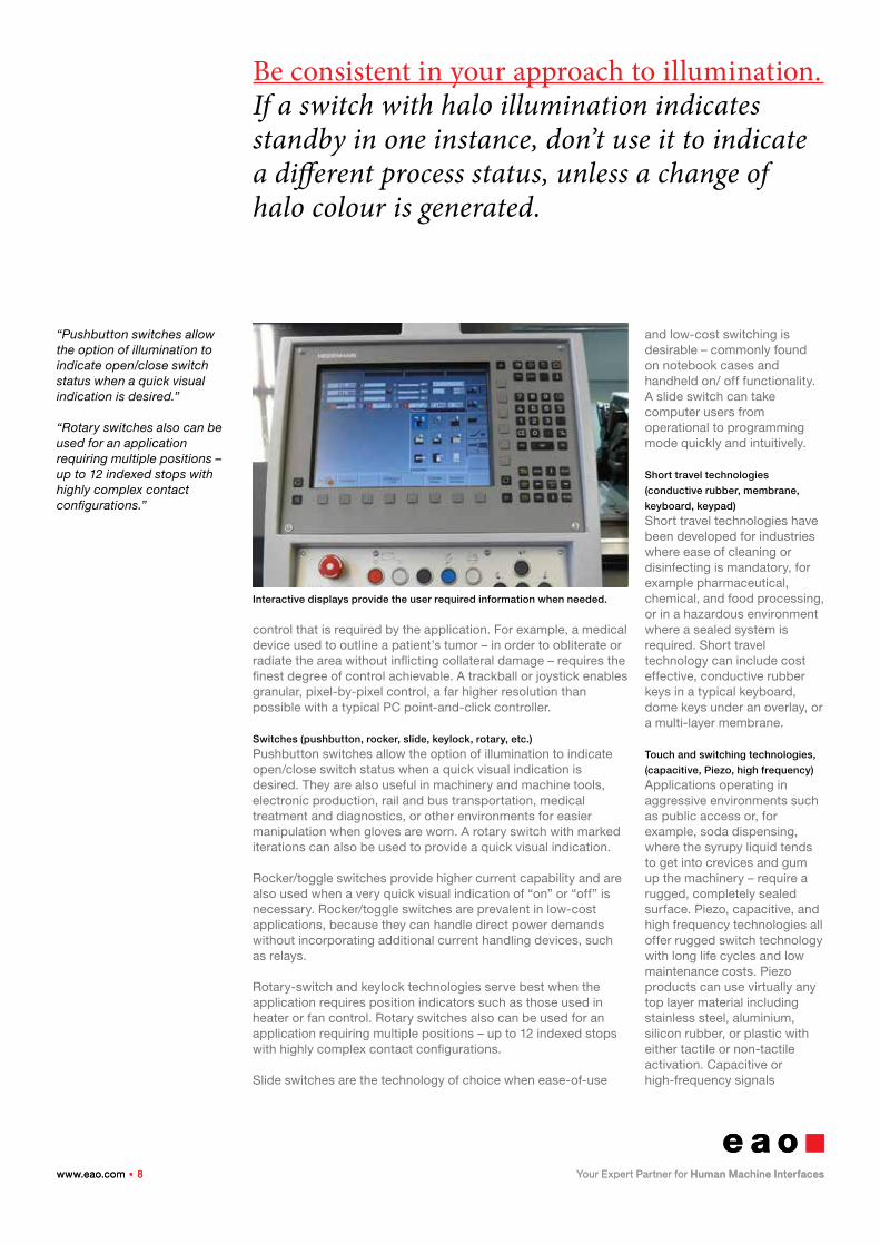
Interactive displays provide the user required information when needed.
www.eao.com . 9www.eao.com . 9
Display technology choices are dictated by the HMI System environment. Display technology choices are dictated by the HMI System environment. Factors such as exposure to shock, operator clothing, ambient illumination, as well as by colour requirements.
“It is important to determine which touch technology will be used in the early stages of the design cycle as the different options offer quite unique electrical and mechanical requirements.”
“Infrared touchscreen technol-ogy projects horizontal and vertical beams of infrared light over the surface of the screen.”
electronically activate an on/off function by changing capacitive load. Capacitive/ high-frequency technologies require the use of non-conductive front panel materials which can be up to 15 mm thick, for example those operating under protective glass within hazardous environments.
Display technologies (LCD, active matrix, OLED, FED, plasma, etc.)
The basic function of displays in HMI applications is to provide an information source – operators interact to obtain information or to prompt for the next screen. Display technology choices are dictated by the HMI System environment and its degree of ambient illumination, as well as by colour requirements. Active matrix LCD technologies are commonly used for colour functionality, while legacy LCD technology is used in applications where monochromatic feedback is sufficient or power consumption is an issue. A newer technology, OLEDS, organic (carbon-based) light-emitting diodes, can currently support smaller displays and offer very low power consumption, but have not yet been widely implemented in commercial applications.
Interactive displays, touchscreen
Touchscreen technologies offer a range of functionalities and characteristics that govern HMI Systems choice according to application and environment. It is important to determine which touch technology will be used in the early stages of the design cycle as the different options offer quite unique electrical and mechanical requirements. Capacitive touchscreen technology consists of an insulator surface such as glass, which is coated
with a transparent conductor that transmits a finger’s electrical current to embedded sensors. The resulting change in capacitance activates the on/off signal.
Capacitive technology offers one-touch or multi-touch options, the latter has been popularized for mobile handheld use by the iPhone. Capacitive touchscreens transmit 75% of the monitor light (compared to 50% by resistive touchscreens), resulting in a clearer picture. They use only conductive input, usually a finger, in order to register a touch.
Infrared touchscreen technology projects horizontal and vertical beams of infrared light over the surface of the screen. When a finger or other object breaks those beams, the X/Y coordinates are calculated and processed. These cost-effective touchscreens can also be used by workers with gloves and are relatively impervious to damage.
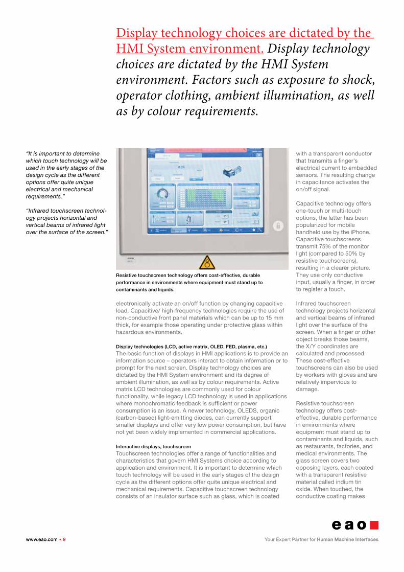
Resistive touchscreen technology offers cost-effective, durable performance in environments where equipment must stand up to contaminants and liquids, such as restaurants, factories, and medical environments. The glass screen covers two opposing layers, each coated with a transparent resistive material called indium tin oxide. When touched, the conductive coating makes
Resistive touchscreen technology offers cost-effective, durable
performance in environments where equipment must stand up to
contaminants and liquids.
www.eao.com . 10www.eao.com . 10
Surface Acoustic Wave (SAW) allows 100% light throughput and perfect image clarity. It’s suitable for displaying detailed graphics, but it’s still a more expensive screen technology.
“Connection and communica-tion can be achieved through several approaches: hard wired connection, serial bus connec-tion, or wireless connection.”
“Hard wired systems require no special tools and are simple, visible, and easy to understand, especially where the HMI interface controls a single machine.”
electrical contact with the coating on the outer layer, the touch coordinates are registered by the controller to activate the on/off function. Resistive touchscreens don’t support multi-touch and require a firm touch by finger or stylus. They also support gloved operation in harsh or cold environments.
Surface Acoustic Wave (SAW) touch technology sends acoustic waves across a glass surface from one transducer to another positioned on an X/Y grid. The receiving transducer detects if a wave has been disrupted by touch and identifies its coordinates for conversion to an electrical signal. SAW serves well in outdoor and harsh environments because it can be activated by a heavy stylus or gloved fingers. SAW allows 100% light throughput and perfect image clarity, making it best for displaying detailed graphics. However, it is the most expensive of the four technologies.
Motion control
Motion control most often employs joystick technology for applications requiring macro control, such as controlling the bucket on a payloader, a robotic arm, or directional control for a piece of materials handling equipment, or pull mechanisms. A joystick can also be used for higher-resolution applications as illustrated by the medical application example above, under “Cursor Control.” Joystick outputs can yield simple contact – open/closure in an N, S, E, and W directional layout. Motion control applications usually work with proportional output, where the joystick is interfaced with a sensor or array of sensors for directional control. An N, S, E, W arrangement of Hall Effect cells
positioned around a central magnet provides low-cost, and stable directional control that is often used in video games or for security surveillance cameras, where motion resolution need not be that fine.
Connecting/communicating with an
HMI System
Once you have established how your HMI will look, feel, and operate, you need to consider how the HMI will connect to and communicate with the core equipment or system under control. Typically, communication can be achieved through several approaches: hard wired connection, serial bus connection, or wireless connection. Each approach has pros and cons – selection will depend on how your HMI needs to fit within your application. Selecting the appropriate communications technologies may include combining some or all of these approaches.
Hard-wired connections
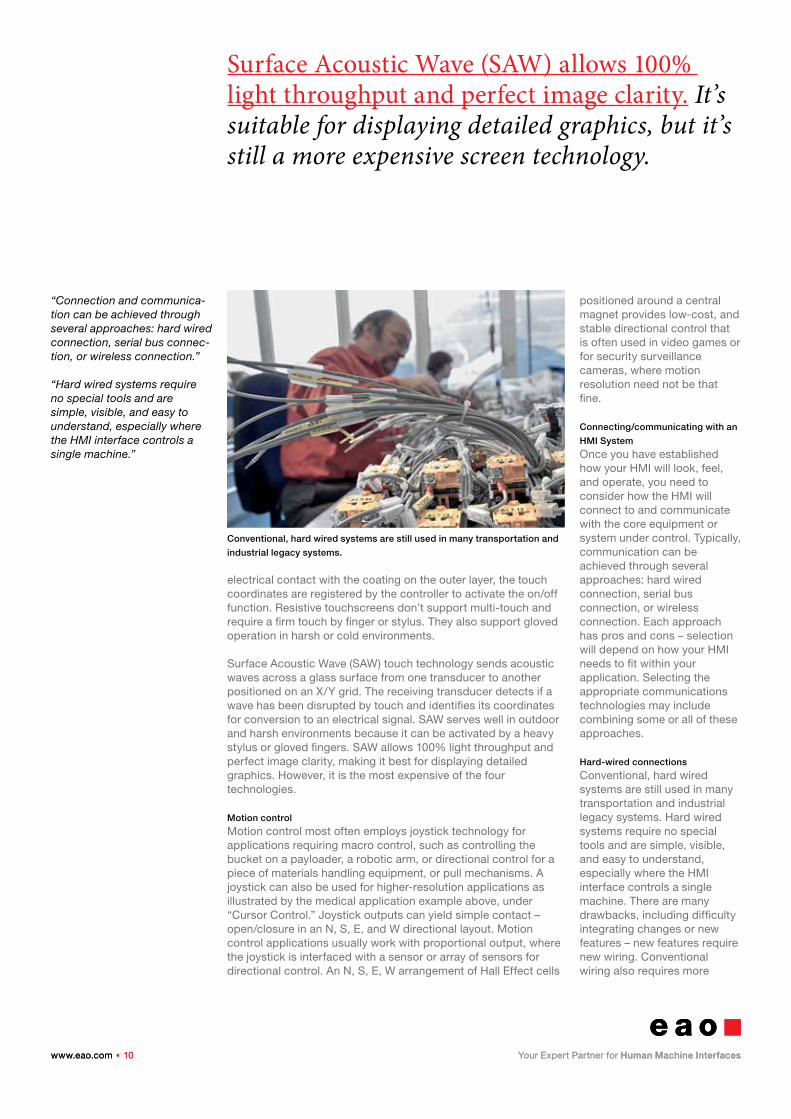
Conventional, hard wired systems are still used in many transportation and industrial legacy systems. Hard wired systems require no special tools and are simple, visible, and easy to understand, especially where the HMI interface controls a single machine. There are many drawbacks, including difficulty integrating changes or new features – new features require new wiring. Conventional wiring also requires more
Conventional, hard wired systems are still used in many transportation and
industrial legacy systems.
www.eao.com . 11www.eao.com . 11
Hard-wired HMI systems may be preferred in the rail industry. Sometimes because of an attachment to legacy technology, but also because of the ripple effect on documentation, maintenance, service, and the effect on training personnel across a vast scale.
“To facilitate faster data transmission rates, devices incorporated serial bus connections – especially in electronics, semiconductor, machining, industrial and process control.”
“Field bus protocols evolved for interconnecting industrial drives, motors, actuators and controllers. Field buses include: PROFIBUS, DeviceN-et, ControlNet, CAN/CAN-Open, KeyLink, InterBus, Foundation Field Bus, and HART.”
space due to the number of wires and the actual size of the wires and larger connectors due to higher pin counts. A hard-wired system is typically heavier and more expensive, which can be detrimental in some applications, such as transportation. As an example, an application requiring a hard-wired assembly or panel might consist of a metal panel plate with 10 switches connected to two wires apiece, 20 wires in all. Each of these wires must be conjoined with 10 application connectors beneath the panel plate. An added illumination requirement would double the wire count, resulting in 40 wire connections to the application.
In some industries, such as rolling stock, users prefer hard-wired HMI Systems, in many instances because of an attachment to legacy technology, but also because of the ripple effect impacting documentation, maintenance, service, and the effect on training operational personnel across the vast scale of the fleet. Such a change represents a very substantial challenge in terms of time, effort, and cost that may not be offset by enhanced efficiency, performance, and revenues.
Serial bus systems
As equipment and control systems became more complex and data hungry, transmission of data became a critical issue. Data transmission depends on distance and speed. The longer the cable length, the lower the transmission speed to keep bit-error rates acceptable. To facilitate faster data transmission rates, devices incorporated serial bus connections – especially in electronics, semiconductor, machining, industrial, process and transportation. A serial bus approach eliminated data transmission slowdowns due to cable length and delivered
reliable, real-time operations and work-in-process feedback.
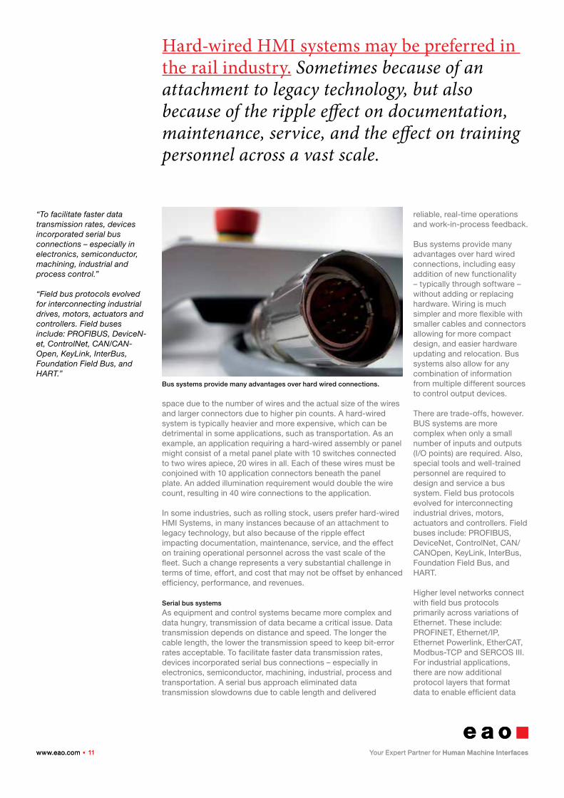
Bus systems provide many advantages over hard wired connections, including easy addition of new functionality – typically through software – without adding or replacing hardware. Wiring is much simpler and more flexible with smaller cables and connectors allowing for more compact design, and easier hardware updating and relocation. Bus systems also allow for any combination of information from multiple different sources to control output devices.
There are trade-offs, however. BUS systems are more complex when only a small number of inputs and outputs (I/O points) are required. Also, special tools and well-trained personnel are required to design and service a bus system. Field bus protocols evolved for interconnecting industrial drives, motors, actuators and controllers. Field buses include: PROFIBUS, DeviceNet, ControlNet, CAN/CANOpen, KeyLink, InterBus, Foundation Field Bus, and HART.
Higher level networks connect with field bus protocols primarily across variations of Ethernet. These include: PROFINET, Ethernet/IP, Ethernet Powerlink, EtherCAT, Modbus-TCP and SERCOS III. For industrial applications, there are now additional protocol layers that format data to enable efficient data
Bus systems provide many advantages over hard wired connections.
www.eao.com . 12www.eao.com . 12
Great strides have been made in the area of wireless capabilities. However, interference, reliability, and security continue to present difficulties in the HMI universe.
“Industrial applications have employed wireless technolo-gies over the last 20 or so years, primarily to take advantage of real-time data transmission, application mobility, and remote manage-ment capabilities.”
“In addition, emergency stop switches, generally referred to as E-Stops, ensure the safety of persons and machinery and provide consistent, predicta-ble, failsafe control response.”
exchange across different networks, buses, and pieces of equipment. There are also buses for specific applications, including BACnet, LonTalk, Konnex, C-Bus and others for building automation; and LIN, CAN J1939, FlexRay, and others for automotive applications. In addition to the above mentioned technologies, there are also USB connections between industrial networks and USB hubs and ports. Buses bring all the switching and illumination wires out as one connection, reducing wiring, assembly, repair/ maintenance time, and weight which in transportation translates into lower fuel costs. Bus connections incur slightly higher upfront costs, but these are outweighed by increased performance and long-term savings.
Wireless connections/communications
Industrial applications have employed wireless technologies over the last 20 or so years, primarily to take advantage of real-time data transmission, application mobility, and remote management capabilities. Corporations and government faced substantial challenges and costs implementing both local- and wide-area networks (WLANs and WWANs), among them lack of standardization, multiple vendors and incompatible equipment, interference issues, and network reliability and security breaches. Great strides have been made in all of these areas, but interference, reliability, and security continue to present difficulties in the HMI universe. A WWAN utilizes mobile communication networks such as cellular, UMTS, GPRS, CDMA2000, GSM, CDPD, Mobitex, HSDPA, 3G, and WiMax. All of these networks offer wide service coverage and are normally used for citywide, nationwide, or even global digital data
exchange. In cellular communication, GSM (Global System for Mobile Communication) is the leader with over 80% market share, followed by CDMA (Code Division Multiple Access). The biggest issues regarding data exchange over a WWAN are the associated costs, bandwidth, and IP management. However, as technologies improve and costs drop, WWAN is predicted to replace traditional microwave, RF (radio frequency), and satellite communication due to its lower infrastructure costs. WLANs transmit data over a shorter distance, normally 100 meters or so. In terms of transmission technology, WLAN uses spread-spectrum or OFDM (orthogonal frequency-division multiplexing) modulation technology to provide the convenience of exchanging data without the limitation of cables. Popular wireless communication technologies being applied to industrial applications include WiFi, Bluetooth, and ZigBee.
Safety considerations
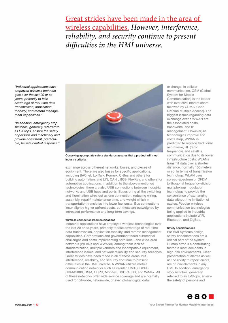
For HMI Systems design, safety considerations are a critical part of the system. Human error is a contributing factor in most accidents in high-risk environments. Clear presentation of alarms as well as the ability to report errors, are crucial elements in any HMI. In addition, emergency stop switches, generally referred to as E-Stops, ensure the safety of persons and
Observing appropriate safety standards assures that a product will meet
industry criteria.
www.eao.com . 13www.eao.com . 13
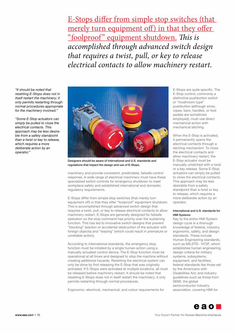
E-Stops differ from simple stop switches (that merely turn equipment off) in that they offer “foolproof” equipment shutdown. This is accomplished through advanced switch design that requires a twist, pull, or key to release electrical contacts to allow machinery restart.
“It should be noted that resetting E-Stops does not in itself restart the machinery; it only permits restarting through normal procedures appropriate for the machinery involved.”
“Some E-Stop actuators can simply be pulled to close the electrical contacts. This approach may be less desira-ble from a safety standpoint than a twist or key to release, which requires a more deliberate action by an operator.”
machinery and provide consistent, predictable, failsafe control response. A wide range of electrical machinery must have these specialized switch controls for emergency shutdown to meet workplace safety and established international and domestic regulatory requirements.
E-Stops differ from simple stop switches (that merely turn equipment off) in that they offer “foolproof” equipment shutdown. This is accomplished through advanced switch design that requires a twist, pull, or key to release electrical contacts to allow machinery restart. E-Stops are generally designed for failsafe operation so the stop command has priority over the sustaining function. This has led to innovative switch designs that prevent “blocking” (wanton or accidental obstruction of the actuator with foreign objects) and “teasing” (which could result in premature or unreliable action).
According to international standards, the emergency stop function must be initiated by a single human action using a manually actuated control device. The E-Stop function must be operational at all times and designed to stop the machine without creating additional hazards. Resetting the electrical system can only be done by first releasing the E-Stop that was originally activated. If E-Stops were activated at multiple locations, all must be released before machinery restart. It should be noted that resetting E-Stops does not in itself restart the machinery; it only permits restarting through normal procedures.
Ergonomic, electrical, mechanical, and colour requirements for
E-Stops are quite specific. The E-Stop control, commonly a distinctive pushbutton switch or “mushroom type” pushbutton (although wires, ropes, bars, handles, or foot pedals are sometimes employed), must use direct mechanical action with mechanical latching.
When the E-Stop is activated, it permanently opens the electrical contacts through a latching mechanism. To close the electrical contacts and allow machinery restart, the E-Stop actuator must be manually unlatched with a twist or a key release. Some E-Stop actuators can simply be pulled to close the electrical contacts. This approach may be less desirable from a safety standpoint than a twist or key to release, which requires a more deliberate action by an operator.
International and U.S. standards for
HMI Systems
Key to the entire HMI System design cycle is a thorough knowledge of federal, industry, ergonomic, safety, and design standards. These include Human Engineering standards, such as MILSTD- 1472F, which establishes human engineering design criteria for military systems, subsystems, equipment, and facilities; federal standards like those set by the Americans with Disabilities Act; and industry guidelines such as those from SEMI, the global semiconductor industry association, covering HMI for
Designers should be aware of international and U.S. standards and
regulations that impact the design and use of E-Stops.
www.eao.com . 14www.eao.com . 14
Observing appropriate standards assures that a product will meet industry criteria. This includes placement of components, legend size and colour, emergency-stop switches and guards, and other ergonomic factors that will improve usability, efficiency and safety.
“HMI Systems must also be able to withstand temperature variations, excessive heat and cold, etc., as well as shock, vibration, and high duty cycle.”
“HMI Components range from different types of actuator functions and illumination to push buttons, keylocks for security, and emergency stop buttons for safety—all in varying shapes, colours, and sizes to make the HMIS easily operable.”
semiconductor manufacturing equipment. Additional HMI specifications are furnished by ANSI, IEEE, ISO, and others.
The EU provides specifications in its EU Machinery Directive for any equipment for domestic, commercial, or industrial applications that have parts actuated by a power source other than manual effort. Meeting this directive earns the equipment a CE mark. There are also standards for public access HMI Systems, including security and cryptography standards for systems that handle payment cards; specific flammability standards and test procedures for transportation systems, and medical device and equipment standards. Depending on the ultimate product application, observing appropriate standards assures that a product will meet industry criteria. This includes placement of components, legend size and colour, emergency stop switch configuration and guards, and other ergonomic factors that improve usability, efficiency, and safety. (See standards)
Applications
Manufacturing and process industries
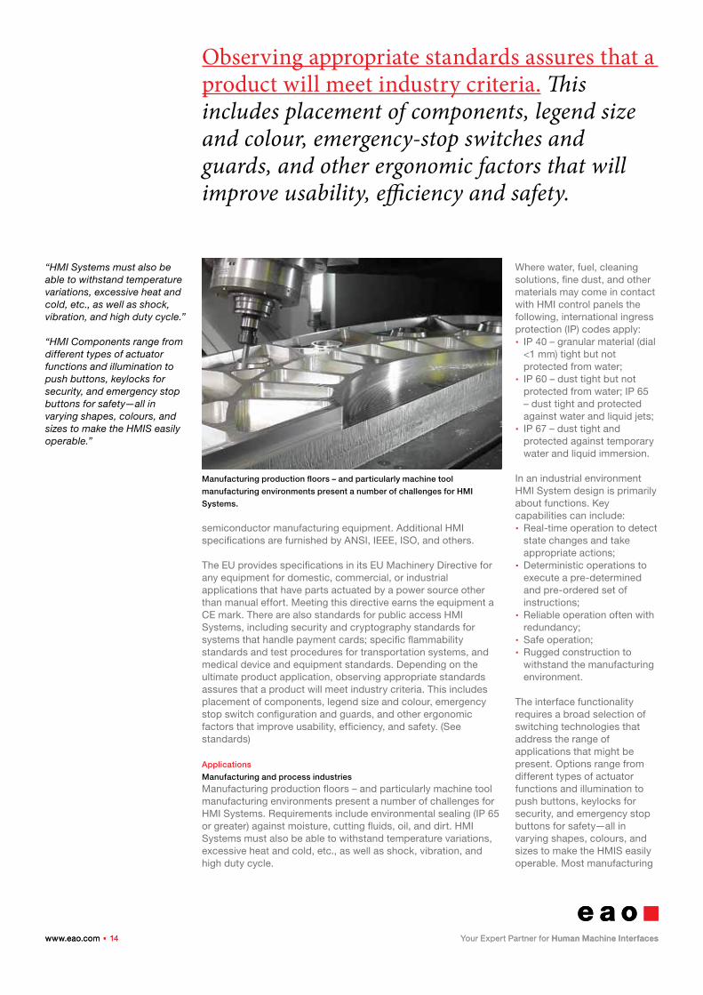
Manufacturing production floors – and particularly machine tool manufacturing environments present a number of challenges for HMI Systems. Requirements include environmental sealing (IP 65 or greater) against moisture, cutting fluids, oil, and dirt. HMI Systems must also be able to withstand temperature variations, excessive heat and cold, etc., as well as shock, vibration, and high duty cycle.
Where water, fuel, cleaning solutions, fine dust, and other materials may come in contact with HMI control panels the following, international ingress protection (IP) codes apply: � IP 40 – granular material (dial <1 mm) tight but not protected from water;
� IP 60 – dust tight but not protected from water; IP 65 – dust tight and protected against water and liquid jets;
� IP 67 – dust tight and protected against temporary water and liquid immersion.
In an industrial environment HMI System design is primarily about functions. Key capabilities can include: � Real-time operation to detect state changes and take appropriate actions;
� Deterministic operations to execute a pre-determined and pre-ordered set of instructions;
� Reliable operation often with redundancy;
� Safe operation; � Rugged construction to withstand the manufacturing environment.
The interface functionality requires a broad selection of switching technologies that address the range of applications that might be present. Options range from different types of actuator functions and illumination to push buttons, keylocks for security, and emergency stop buttons for safety—all in varying shapes, colours, and sizes to make the HMIS easily operable. Most manufacturing
Manufacturing production floors – and particularly machine tool
manufacturing environments present a number of challenges for HMI
Systems.
www.eao.com . 15www.eao.com . 15
Functions that are used quite often such as stop/start and quick positioning can be associated with discrete push buttons. Frequently used controller sequences can be associated as a macro of functions, activated by a switch on the control panel as well.
“There are two distinct categories of HMI Systems related to transportation: operator controls and passen-ger controls.”
“Meeting industry best practices is important in placement of components, large surface area, legend size and colour, emergency stop switch configuration, protec-tion guards and shields, and other ergonomic factors.”
equipment panels have a basic controller for the higher-level functions of the application. Typically alphanumeric data input is required, which might be through a keyboard or other data input device. Displays with basic functionally such as display of key data, alarming and system status may also be used, though without a lot of graphics. Because operators frequently have to move tool configurations as they work, controls incorporate scrolling between screens and setup to enter the job parameters. Functions that are used quite often such as stop/start and quick positioning can be associated with discrete push buttons. Also frequently used controller sequences can be associated as a macro of functions, activated by a switch on the control panel as well.
Communications technology could include hard-wired connections or any number of bus connections such as Ethernet, Profitnet, CAN/Open, etc. Wireless technologies can be used in this environment but interference from the core machinery itself must be taken into consideration as a risk factor. Integration with other equipment or systems in a machine centre environment may include infrastructure—such as conveyor belts and other materials handling equipment.
In many manufacturing environments the HMI System is not only an interface to equipment under control, but also to a SCADA system. Here a computer system coordinates and may control processes in real time. The system would include the HMI interface as well as programmable logic controls (PLCs), remote terminal units (RTUs) and sensors to log data, update process
status and send alarms. The HMI software for a SCADA system may actually “mimic” the real manufacturing process in a diagram so the operator can see the manufacturing process and the effects of operator actions on that process. Where once HMI software was closely tied to the hardware in the SCADA system, today there is more opportunity to mix and match components.
Transportation industry
There are two distinct categories of HMI Systems related to transportation: operator controls and passenger controls. For operators of rail vehicles, buses, and emergency vehicles, the key to an effective HMI System is consistent and predictable performance with time-proven controls that are familiar to multiple operators. As transportation systems grow more complex, operator controls should be easier to understand and use in order to reduce the risk of human error. Meeting industry best practices is important in placement of components, large surface area, legend size and colour, emergency stop switch configuration, protection guards and shields, and other ergonomic factors. The goal in designing operator controls is to provide optimal usability, efficiency, and safety. Measures to assure safety and usability include: flush-mounted switch controls, rotary and linear actuators, and indicators, as well as screw
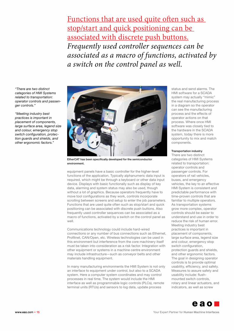
EtherCAT has been specifically developed for the semiconductor
environment.
www.eao.com . 16www.eao.com . 16
ADA regulations require that controls be accessible for passengers with disabilities—utilizing the overall simple functionality and ease-of-use criteria applicable to all public access applications.
“An HMI System for a locomo-tive, for example, could include alarm and status signals from a variety of the vehicle’s subsys-tems, such as braking, propulsion, positive train control, surveillance, HVAC, and sander systems.”
“The confined space of passenger car interiors are subject to stringent regulations regarding the flammability of combustible materials.”
terminal or PIT (push in terminals) to protect against accidental operation. Sealed light emitting diode (LED) illumination offers long life, bright illumination, and also saves on power consumption. Additional lens protection can be achieved with extended or sealed rings and lens caps. Multiple shapes, textures, and haptic response are used to differentiate specific control functions and provide a tactile indicator without the need to look at the controls. Also, Operator HMIs are designed to allow for fast and complete test procedures required prior to operation.
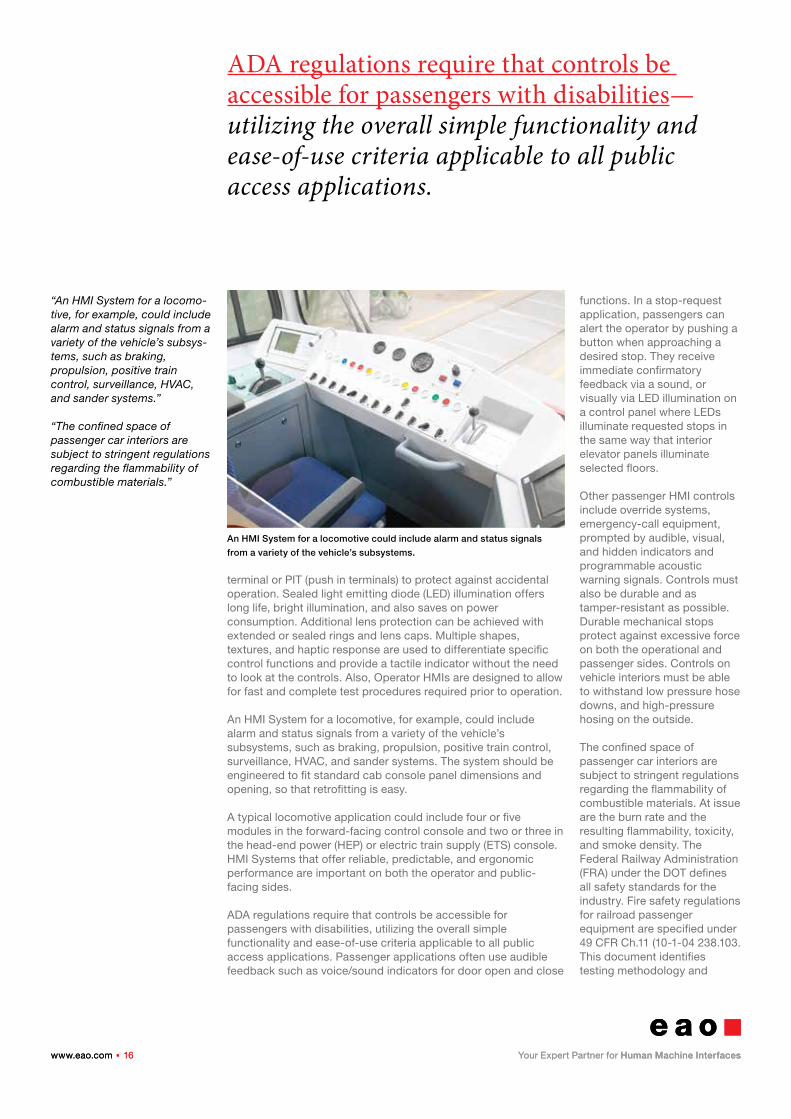
An HMI System for a locomotive, for example, could include alarm and status signals from a variety of the vehicle’s subsystems, such as braking, propulsion, positive train control, surveillance, HVAC, and sander systems. The system should be engineered to fit standard cab console panel dimensions and opening, so that retrofitting is easy.
A typical locomotive application could include four or five modules in the forward-facing control console and two or three in the head-end power (HEP) or electric train supply (ETS) console. HMI Systems that offer reliable, predictable, and ergonomic performance are important on both the operator and public-facing sides.
ADA regulations require that controls be accessible for passengers with disabilities, utilizing the overall simple functionality and ease-of-use criteria applicable to all public access applications. Passenger applications often use audible feedback such as voice/sound indicators for door open and close
functions. In a stop-request application, passengers can alert the operator by pushing a button when approaching a desired stop. They receive immediate confirmatory feedback via a sound, or visually via LED illumination on a control panel where LEDs illuminate requested stops in the same way that interior elevator panels illuminate selected floors.
Other passenger HMI controls include override systems, emergency-call equipment, prompted by audible, visual, and hidden indicators and programmable acoustic warning signals. Controls must also be durable and as tamper-resistant as possible. Durable mechanical stops protect against excessive force on both the operational and passenger sides. Controls on vehicle interiors must be able to withstand low pressure hose downs, and high-pressure hosing on the outside.
The confined space of passenger car interiors are subject to stringent regulations regarding the flammability of combustible materials. At issue are the burn rate and the resulting flammability, toxicity, and smoke density. The Federal Railway Administration (FRA) under the DOT defines all safety standards for the industry. Fire safety regulations for railroad passenger equipment are specified under 49 CFR Ch.11 (10-1-04 238.103. This document identifies testing methodology and
An HMI System for a locomotive could include alarm and status signals
from a variety of the vehicle’s subsystems.
www.eao.com . 17www.eao.com . 17
EtherCAT Industrial Ethernet was developed for the semiconductor environment. EtherCAT provides superior performance, bandwidth, and topology flexibility to cover the range of semiconductor manufacturing equipment with a single technology.
“Applications in semiconductor tend to have many operator terminals. They often consist of touchscreen displays that are essentially flat-screen comput-ers of various sizes interfaced to production machines.”
“The medical environment is quite broad with applications that include clinical, diagnos-tic, patient use, or skilled operator use equipment such as Magnetic Resonance Imaging (MRI).”
performance related parameters required to maintain a safe operation environment. It is the American National Standards Institute (ANSI) that specifies the detailed testing methodology and performance criteria parameters. For example, ASTM 162-02a covers testing for the surface flammability of materials (burn rate) and ASTM 662-03, testing for the specific optical density of smoke, and Bombardier SMP 800C, for testing for toxic gas generation.
Semiconductor production
Applications in semiconductor tend to have many operator terminals. They often consist of touchscreen displays that are essentially flat-screen computers of various sizes interfaced to production machines. The environment is generally extremely clean. Emergency stops are always a discrete function in this environment. The SEMI S2 Guidelines identifies them as Emergency Machine Off (EMO) stops, distinguished from E-stop configurations used in other industries. The primary difference is SEMI’s requirement of a guard over the switch, which allows operation with the palm of the hand, in order to guard against accidental shutdown and the loss of work-in-process. Other specific characteristics include some use of tethered pendants with operations brought to a tethered box—both wired and wireless boxes allowing the operator to move away from the main control panel to perform tasks such as setting parameters, for example. Most other functions are similar to other manufacturing environments.
Communications use a range of hard-wired/bus control and wireless for the tethered applications. A specific version of Ethernet has been developed for the semiconductor environment. Called EtherCAT Industrial Ethernet, is in use in a wide variety of semiconductor and flat panel display manufacturing operations. EtherCAT provides superior performance, bandwidth, and topology flexibility to cover the entire range of communications requirements in semiconductor manufacturing equipment with a single technology: from process control via control
computer integration to high-end motion control applications.
Medical equipment
The medical environment is quite broad with applications that include clinical, diagnostic, patient use, or skilled operator use equipment such as Magnetic Resonance Imaging (MRI). Diagnostic equipment manufacturers focus on patient-facing priorities including ergonomics and reassurance. Large diagnostic equipment like MRI, Computed Tomography (CT), or other Diagnostic X-Ray machines, where the patient is being scanned from a stationary position, have both operator and patient controls to stop the process in case of patient discomfort. The operator is highly skilled, and the control station is very similar to a computer workstation.
The controlling interface keyboard is typically comprised of a cursor control device and short travel technology, which may be located outside of the equipment suite. Clinical equipment could be an infusion or blood pump, or machine for dialysis control. Cleanliness is a key priority, incorporating antimicrobial surfaces with the ability to be sterilized. Most functions are in the hands of a skilled operator but clinical equipment may be operated by a skilled patient/user as well. Displays are used to show key data, alarming, and system status. Touchscreens may be used but must be resistant to cleaning solutions to limit the spread of infection.
Communications include CANbus, wired, and Ethernet, but wireless communication is difficult in this environment. It is thought to be a little less reliable, susceptible to signal interference, and may interfere with other equipment due to unsafe radiated emissions.
Summary
The effectiveness of the HMI System — and consequent enhanced productivity of the user — depends upon an exacting design process that incorporates all technical, ergonomic, and communication requirements. Connectivity technologies linking the HMI to the core
www.eao.com . 18www.eao.com . 18
The impact of the human/machine interface is much more significant than its basic functionality. HMI Systems are the principal point of contact between the user and a machine or process.
“Selecting the appropriate communications strategy from hard-wired, serial bus, wireless, and other options demands a careful evaluation of the application and, in most cases, a blend of available technologies.”
application directly affects both operator and overall system performance. This key interconnection is critical to overall successful use of the system. Selecting the appropriate communications strategy from hard-wired, serial bus, wireless, and other options demands a careful evaluation of the application and, in most cases, a blend of available technologies.Wireless communications can deliver real-time data transmission, application mobility, and remote management capabilities.
U.S. and industry standards by application
Manufacturing and Process Industries (shop floor applications) International standards:
EU Current Machinery Directive, from Dec. 2009 http://www.conformance.co.uk/directives/ce_new_machinery.php
MIL-STD-1472F, addresses human engineering design criteria for military systems, subsystems, equipment, and facilities
IP (International Ingress Protection) codes
ISO 9001 and ISO 14001
CE Mark – Meets European Union (EU) requirements and guidelines for safety, health, or environmental requirements
CSA International – Canadian Standards Association provides product testing and certification
UL, C-UL – Underwriters Laboratories, U.S./Canadian rating organization
VDE – Electrical, Electronic & Information Technologies, a German testing organization
DIN EN ISO 13850: 2008 (Safety of machinery – Emergency stop – Principles of design) The first edition of ISO 13850 (published in 1996) replaced the EN 418 “Emergency Stop” directive in March 2008. Significant changes in this second draft:
Mandate manual resetting of E-Stops. Require E-Stops to use mechanical latching. State that the revision will remain unchanged until 2010.
U.S. Federal:
ADA (Americans with Disabilities Act) Standards for Accessible Design, 28 CFR Part 36 http://www.ada.gov/stdspdf.htm
NEMA (National Electrical Manufacturers Association) similar to the international IP standard, e.g., the NEMA 4 standard is similar to IP 65
ANSI (American National Standards Institute)
Industry standards:
IEC Safety Integrity level (SIL) http://www.iec.ch
Transportation Industry
ISO (International Standards Organization): 9000, specifically for railway
EN 5155 develops standards for electronics on railway passenger vehicles
The Federal Railroad Administration (FRA, under the U.S. Department of Transportation) is responsible for defining standards covering safety issues
ASTM (under ANSI) specifies testing procedures in transportation; A range of ASTM standards provide methodology and performance specifications for testing FRA regulations flammability testing
49 CFR Appendix B to Part 238 – Test Methods and Performance Criteria for the Flammability and Smoke Emission Characteristics of Materials Used in Passenger Cars and Locomotive Cabs http://cfr.vlex.com/vid/238- flammability-smoke-locomotive-cabs- 19946592##ixzz0n5YL4A8X
www.eao.com . 19www.eao.com . 19
Connectivity technologies linking the HMI to the core application directly affects both operator and system performance. This key interconnection is critical to overall successful use of the system.
Contact
EAO AGTannwaldstrasse 88CH-4601 Olten, SwitzerlandTel. +41 62 286 91 11Fax +41 62 296 21 [email protected]
More information
www.eao.com/downloads
Americans with Disabilities Act (ADA) American National Standards Institute (ANSI)
IEEE
IRIS (International Railway Industry Standard) Rev. 02; ensures products meet globally recognized quality levels
Semiconductor Industry Semiconductor Equipment and Materials International http://www.semi.org/en/ index.htm
Safety Guidelines for Semiconductor Manufacturing Equipment SEMI S2-93
Safety Guidelines for Ergonomics/Human Factors Engineering of Semiconductor Manufacturing Equipment SEMI S8-95
Medical Industry
ISO Standards for medical devices – ICS 11.1100.20 and ICS 11.040.01 [5], [6]
Quality and risk management – ISO 13485 and ISO 14971
IEC 60601-1 and IEC 62304 for medical software
U.S. FDA 21 CFR Subchapter H – Medical Devices [7]
Food, Drug, and Cosmetic Act – Section 510(k) – for pre-market notifications Americans with Disabilities Act (ADA) PCI 2.1 encryption standards.