Embed Size (px)
Citation preview
TECHNICAL BOTES f+e NATIONAL ADVISORY COMMITTEE FOR AERONAUTICS
. --
NO. 713
A COMPARISON OF SEVERAL TAPERED BlNGS
DESIGNED TO AVOID ZIP STALLING
By Raymond F, Anderson Langley Memorfal Aeronautfcal Laboratory
- TVashfn@on June 1939
NATIONAL ADVISORY COMMITTEE FOE AERONAUTIGS
l
TECHNICAL N&E NO. 713 --
A COMPARISON OF SEVERAL TAPERED WINGS
DESIGNED TO AVOID TIP STALLING
By Raymond F, Anderson
SUbi?.fARY
Optimum proportions of tapered wings were investigat- ed by a method that Involved a comparison of v5ngs de- sfgned to be aerodynamfcally equal. The conditions of aerodynamic equality were equalfty in stalling speed, in induced drag at a low speed, and in the total drag at cruising speed. After the wings were adfusted to aerody- namic equivalence, the weights of the wings were calcu- lated as a convenient method of indicating the optimum . wing. The aerodynamic characteristics were calculated from wing theory and test data for the airfoil sections* Various combinations of washout, camber increase in the airfoil sections from the center to the tips, and sharp leading edges at the center were used to bring about the desired equivalence of maximum lift and center-stalling characteristics.
In the calculation of t?te weights of the wings, a simple type of spar structure was assumed that permitted an integration across the span to determine the web and the flange weights. The covering and the remaining weight were taken in proportion to the wing area. The total weights showed the wings with camber and washout to have the lowest weights and indicated the minimum for wings with a taper ratio between l/2 and l/3.
IBTBODUGTIOW
Many investigations have been made of the aerodynamic and the structural aspects of tapered wings with a view to finding the best taper ratio. Investigations of taper ratio are reported in references 1 and 2. A general dis- cussion of tapered wings is given in reference 3. Although
2 N.A.C.A. Tei=hnic'al Note.'Bo; 713 ..
drag and weight were considere'd'in're'ferences 1 and 2, the effect of taper ratio on the maximum lift and the manner of stalling of wings was not considered. The effect of taper ratio on the maxfmum 1Pft'is cdnsider&ble. The tfp stall that usually results from the use of tapered wfnga, moreover, evidences itself as instabilfty'ih roll at an- gles of attack less than that corresponding to the maximum lift coefficient. This condition is generally recognized as undesirable from the point of view of handling charac- teristics fn low-speed flight.
It i.s accordingly considered herein that wfnge should be designed to avoid tip stallfng. With this point of view,
..wings.of different taper ratio were designed to be aerody- namfcally%qual; that Is, equal in stalling speed, is fn- duced drag at a low speed, and in,total drag at cruising speed. The weights were then calculat8d to indicate the "optimumn wing (the wing of lowest weight).
In che calculation of the maximum lift, the areas were so obtafne'd that they approximate the values which would be required by wings with full-span flaps. The effect,of p.artdal.-span flaps was not considered. .
Wings with' taper ratios of l/2, l/3, and l/4 were COP- sfderod for a large airplane. In the determinatfon of the maximum lift coefficients, a margin against the stalling of the tips was specified. For the three.taper ratios the stalling of three sets of wings was consfderedl wings with no washout or,cambar increase in the airfoil sections from oenter to tfp (referred to as the "basic" series, to be de- scribed later}; wings with washout; and wings with washout and camber increase from center to tips. For each of the three sets of wings, lift-spoiling devfce8, such as sharp leading edges, were assumed at the center of the wings to make up the required balance of the mar-gin against stalling of the tips. This procedure is practically equivalent to fncreasing the lift by the use of leading-edge slots over all of the span except for a small portion of the center. The comparative effects of washout and,camber should thsre- fore be nearly independent of whether the lift is decreased at the center or increased at the tips.
i
N.A.C.A. Technical Rote Bo. 713 c
SSSUMPTIOW FOR TRE AERODYNAXIC CALCULATIOBS
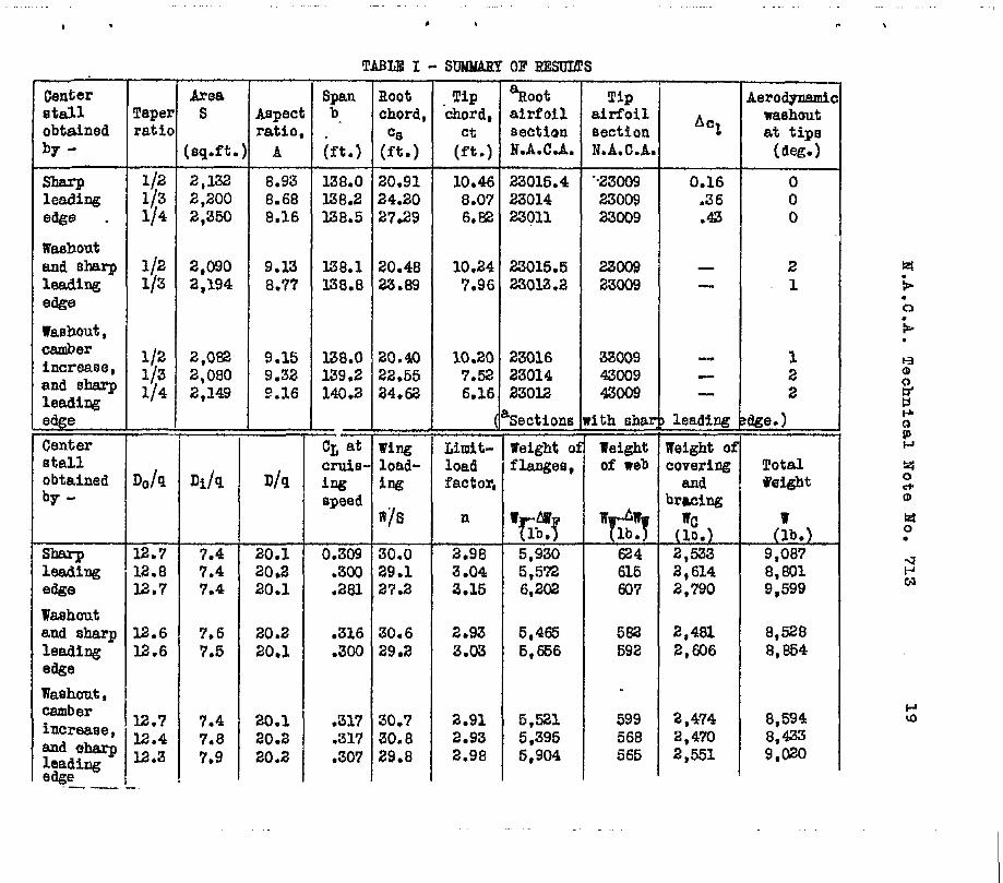
The wings had straight tapers and rounded tfps and were of a size suitable for a four-engine airplane of 64,000 pounds gross weight with a wing loading of approxi- mately 30 pounds per square foot. The tip chord of the trapezoid enclosing the rounded tfps was used to define the taper ratio, as in reference 4. The distribution of thicknass along the span and of camber and washout, nhon they wora used, was linear. A thickness ratio of 0.09 was taken for the airfoil sections at the tips. A basic wing, used to determine,the aerodynamic values to be equaled by the other wings, had a root thfckness ratio of 0.14, an area of 2,200 square feet, a taper ratiio of l/3, and a span of 138.2 foot. The method of calculating the dimen- sions of the other wings fill be gisen later. The symbols used aro listed in an appendix.
Prevention of TCfp Stalling
For the first series of sings of varying taper ratio, the method for prevention of tfp stalling was the use of sharp leading edges. to reduce cl at the center of the max wings. Th5s series of wings was called the basic series because it ticluded the basic wing of taper ratio l/3 used to establish the aerodynamic values. The E.A.G.A. 230 se- rfes airfoil sections listed in table I were used.
For a second series of wings, washoutwas used: and, for the third series, washout was combined with an increase in camber of the airfoil sections from center to tips. The increase in canber produces an increase in the cl of
max the sections near the tips and thereby causes the stalling point to IZOVB inward. For the wings with washout, small amounts of washout were used to prevent excessive increase in the induced drag. Sharp lepdinp edges at the canter of the winqs were then used to make up the balance of the mar- gfn required against stalling of tha tips. Tha case of taper ratio l/4 was omitted for the series with washout alone because too thin a wing would have resulted.
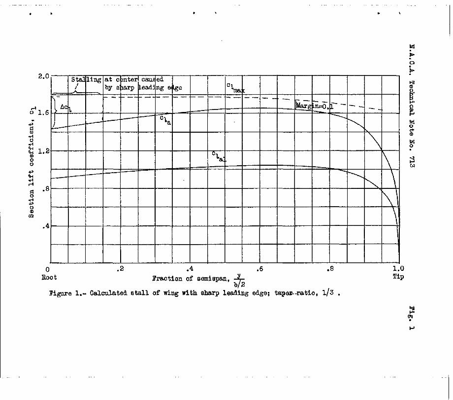
For all the wfngs, in order to insure the,avoidance of tip stalling, a certain' cl 0.7 b/2 when CL,,,
mar&n was specified at was reached. (See fig. 1.) The mar-
4 H.A.C.A. TechnIcal Nats No: 5'13
gfn required dep'ended on the calculated spanwise position of the stallfng point withaut sharp leading edges. This point occurred where a cI curve corresponding to the spanmise load distribution became tangent to the ct,,, curve, as outlined in detail in reference 4. When this. stallfnq point was at or inside 0.7 b/2, the cl margin at 0.7 b/2 was taken as 0.1; When it was outside 0.7 b/2, the margin was increased in the ratio of the distance from the center of the wing to 0.7 b/2. The pkovisfon of this amount of margin when stalling started at the center gave a calculated.'gositive damping in roll at the stall that should prevent suddeG dropping of a wing.
Conditions of Aerodynamic Equality
ftY, For the first of the conditions of aerodynamfc equal- equal stalling speeds, plain airfoil sections were
assumed when 0~ max was computed because of the atraflabil-
ity of the c&m,, data. The Reynolds Number at stalling speed was made to fall within the usual range for an afr-r plane of the size assumed by basing it on the stalling speed with flaps, so that the wings had approxLm.ately the same areas as wings with full-span flaps. That the condi- tion of stalling-speed equality would not be appreciably altered by considering the wings to have full&span flaps was verified from figure 60 of reference 5, which gives fhe 'Itmax increments produced by flaps. (The range of the average thickness of the wings was small.)
'As the stalling speed VS is equal to/r mar
and =,: was fixed, the stalling-speed condition required that the product SCL
max for -each wing be equal to the
product for the basic wing (taper ratio l/3).
The.second condition was that the induced drags should be equal&at a speed corresponding to a CL of L.0 for the basic wing (low-speed condiffon). The induced drug rathar than the total drag was used because the induced drag was nearly alI of the.drag and was relntfvoly easy to calou- late. The induced drag, with tho effect of twist c i'n? eluded, may be found from
N.A.S.A. Technical Note Ho. 713 5
Di = wga 'I- + ltg E a0 qnb?l
v + q S (E ao12 w
or the spans required to makB.t.he induced drags equal may be expressed
. I .
/
b J
ub Di b 6 = i CDf - W E: a:v -
(2)
b g q S (E a,>' wl
where the subscript b refers to the basic wing, and
Dib = wg2
q .i’r bb2 ub (3)
Equation (3) is equation (1) with the last two terms omit- ted because the basic wing has no twist. These equations mere derived from the formula for CD given in reference 4. i
The third condition, equal cruising speeds, was satis- fied by making the drags equal at cruising speed, as the power was assumed constant. Cruising speed corresponded to a % of 0.3 for the basic wins.
METSOD OF GALGULATION
Proportions and Aerodynamic Characteristics
The method used for calculating CD,,, CD , and the 0
other aerodynamic characteristics of the wings has been found to give results that agree well with test results (references 4 and 6).
The method of calculating the maximum lift coefficient for the basic wing is illustrated in figure 1. For this wing, c'1 =ct because there is no washout and therefore
Cl =o. Stalfinq was calculated to occur without any sharp
leEding edge at 0.7 b/2; that is, CT would reach a cl Max
first at the 0.7 point. (See reference 4 for a detailed
6 N.A'.C.A. Technical Note No%* 713
explanation.) A.value -of cl, of 0.1 less than the
cZ at y= !) was then the' lift coefff- max
0.7 b/2 (cz a
cient corresponding to GDmax. Numerically, GD,,x =
Cz, 'lcza l * where cz was taken at y e 0.7 b/2.*. The ai
values of cl max
at the center of the wing were then con-
sidered to be, reduced by a sharp leading edge to the val- ues of cz , as shown, so that stulling would be&n at
a the oenter of the wing. The values of cl used for
mux calculating CL for this wing mere taken from reference 5. max
The value of the induced drag at the lo&speed condi- t%on for the basic wing, Ddb, to be used in finding the spans of the other wings was calculated from equation (3).
The drag of the basic wing at cruising speed was cal- culated in terms of q, in the form
D Do =i- Di
a=s I- (4)
The value of Do/q was calculated for a GD of 0;3 and for the crufsing-speed Reynolds Number (as outlined in reference 4) by a graphical integration along the span of the section drags from
DO '1
9= J
cd 0 c as
0
The values of cd, were taken from reference 7 for the
basic wing as well as for the others, The value of Di/9 was calculated from equation (3) for a value of q corre- sponding to the crufsfng speed*
TVith the values for the basic wing established, e'qual values for the other wings were found by successive approx- imations. For the other two wings of the basic series, a root thickness and an area were assumed that, it was hoped, would, produce the desfred characteristics. An approximate
N.A.G.A. Technical Note Ho. 713 7
.
Y
s$an was then found from equation (2) so that c and cl, a
could be found. For these values, OL . was-then calcu- max
lated in the same manner as for the basfc wing.
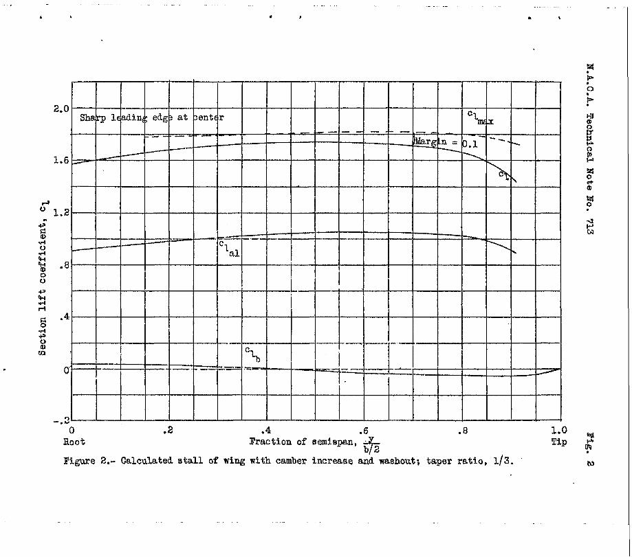
For the wings with washout and with washout and cam- ber increase, airfoil sections and washout were assumed. The value of CI, was then calculated as for the basic
max wing, except that ~1% due to washout vas combined wvith
% to obtain cE, as shown fn figure 2.
From the values of CD TIlLtX
for the wings, a more accud
rate value of S was fcund~f.c-r -each wing to obtain a prod- uct of s and %,,, equal to the value for the basfc wing. The apprcxlmate span was used to calculate the as- pect ratio so that the induced-drag factors u, V, and W could be found from reference 4. A mere accurate value of the span to obtain the required induced drag at low sDeed cculd.then be found from equation (2). A value of a0 of 0.1 per degree was used. Frcm S and 3, more _accurate values of c could be found so that D/q could be computed,
The value of D/q at cruising speed for e@ch winq was next .found from equation (4). where the value of Do/q was calculated from equation (5) for a CD correspond+g to the crufsinq speed and the wing area. The value of Di/q was then found from equation (1) for a value of q correspond- ing to the cruisbq speed. If the values of D/q calcu- lated in this manner were not close to the value for the basfc wing, new values of root thickness ratio were assumed and the calculations were repeated,
Successive approximations were repeated in this manner until the required values of SCD max' b, and D/q were ob-
tained. Two or three approximattons were usually required, The resulting dimensions and the values of D/a_ are given in table I. The amounts of washout required were a compro- mise between a high CDmax and a loa induced drag. In or-
der to investigate the effect of greater washout, calcula- tions were made for a wing with camber increase and wash- out with a taper ratio of l/3, and with E: = - 4', but the results were not included in the table because the noiqht was excessively incraased. It should be noted that
N.A.C.A. Technical 8ate No. 713
the washout is "aerodynamic"; that.is, it is measured, not from the chord, but from the ,zero-lift directions of the root and the tip sections,
TPeight of the Wings
The load factors for calculating the weiphts.of the wings were computed as specified in reference 8. A high speed of 240 miles per hour was used with a gust,of 30 feet per second, as given for condition I in reference 8. The lift-curve slope'was computed from figure 2 of reference 4. The values of the limit-load factors n, computed in this manner, are listed in table I.
The ON to be used for calculating the load on the wings was then found from
n(Wg - WI CN = --- qs ,
where w4 is the gross weight; m, the assumed wtng .nefght; and corresponds to a speed.of 240 miles per
hour. The lozd ddstrfbution per unit length along the span, '1, was then found from 1 = q ct c where q maa
found as.in reference 4 from
=t = CW Ot,, -I-’ qb
For the wings without twist, cl is zero. b
The values of ct and ct b
mere calculated from
the'load-distribution zta given in reference 4 so that. the variatfon of the load distribution with taper was taken into account.. From the dfstribution of load aoross the span, the distribution of the shear and the moment could be eaafly found.
The shears and the moments were assumed to be carried by a single spar .wfth a simple type of structure as shown in ffqure 3, so.t.hat the weights of the material could be
N.A.C.A. Technfcal Note.Ho.-71.3 9
found by an integration across the.span. The torsion load not slimbated by assuming the spar to be located at the lift center of each section may be considered to be car- rfed by the skin.
The relfeving loads caused by the engines and the fu- selage were taken into account SO that the total wing weights were calculated in the form
w = ww - AWW t Wp - AWF + WC (8)
The weights thus calculated may not agree wfth the weights of actual airplane wings because of the simple type of structure assumed and the improbability that all the material will develop the stress assumed. The effects of the assumptions should, however, be similar on all the wings so that the correct relative wefghts should be ob- tainable.
The load d5strfbutions across the semispan of the wings, computed in the manner previously gfven, had the form represented in fiiqure 3. From the load, or ctc, curves, the shears and the moments at any point y along the semispan mere found from
The shear bracing was assumed to have an angle of 45', as shown fn figure 3. For-a unit length along the span dy corresponding to a unit length of bracing dL, the weight of the web will be
dVw = p g FS dy sdL=p----=
2~ FS 0.707s 0.707 dy (111
S -- where -
10 N.A.G.A. Technical Note No.. 713 - .I .
P is the specffic weight (assumed to 'be an alumf- ntlm all.oy wcfghing 0.1 pound per cubic inch).
S, allowable stres's.
f, force in a diagonal.,
For a factor of safety of 1.6, the web wefght for both halves of the wing is then
b/2 (1
Ww= . 4 x 1.5 $ J
FS w (12 1 0
A conservative stress of 20,000 pounds per square inch was assumed in calculatfng WV.
In the calckation of the &eight of the flanges, the moment at any point along the span was considered to be carried by tension and compression in the flanges. If F is the force in a flange (fzig. 3) and if the effective thickness of the beam t? is taken aa 0.9 the wfng thick- ness, then the weight of a upit length of one flange will be
d”F =P
The weight of uppor and the wing, with a factor
ff dy = P & dy
lower flanges for both halves of of Safety of 1.5, is then
1$=4x
From equations (12) and (14), the web and the flange
(13 >
(14)
weights were found by graphical integration of curves of FE and M/t' along the semispan. Values of 8 of 20,000 pounds per square inch for compression and 30,000 pounds per square inch for tensfon were used to calculate the flange weights.
In the calculation of the weight decrements due to the relieving loads, the concentrated loads shown in figure 3
1
were considered, and the useful loads were omitted to be con- servative. The shear was assumed to bo taken off at the I
N.A.C.A. Technical Note 'No'. 71.3 11
fuselage mall so that half the weight of tho body TB/2 acts at a distance yB. The weight of the body consists of the complete weight of tho fuselage and the tail, less the useful load. The-nacelles and the cowling were includ- ed in the power-plant weights, Wpl and Wp2, and the landing-gear mefght was included in Wpi. The correct rel- atfve weights of the relttevinq loads mere established by a weight analysfs.
The ,relieving effect of each load on the web mefght is proportional to the load times its drstance from the center. Then, from equation (II), the mob-neAght decrement for both halves of the mfnq, with a factor of safety of 1.5 and a limit-load factor n, may be written
Am, = 4 X 1.5 pn 2 s c 2 yB * 'PI ST, + %s ys (151
The same value of s was used as in the web-weight calcu- lation.
The relieving effect of each load on the flange weight is proportional to the moment trmes the distance of the load from the center. Then Lf t,' is 0.9 the root thick- ness, the weight decrement due to the re.lieving loads for both flanges and both halves of the wing will be, from oqua- tion (13),
4 X 1.5 pn AVp= - t,r s yBa -+ 'P Y* +-BP ;pz" (16)
1 1 a
The same values of s ivere used as for the flange-weight calculation.
The final weight item -F,; which included the cover- ing and all of the structural veight other_.tfian that of the beam, was taken as a constant proportion of the ving area* The net wei&ts of the various structural parts of the wing and the total wei.ghts are lfstod in table.1. As each wing weight was found, it was compared with the as- sumed weight used in equation (6) and the 'calculations were repeated until the value of the neight assumed did not affect the final rrefqht.
12 N.A.C.A. Tedmica Note-Ho. 7'13
RXSULTS BND DISCUSSION
From the dimensions and the characteristics of the ti kings listed in table I, the effect of'changee of the
taper and of the method to prevent tip stalling may be noted, The effect of a change of the taper on C&mar .and
'on the resulting area may be explained as follows. As.the taper is increased, cl increases from the center to the tip of the wing. In addition, the Reynolds Xumber de- creases toward the tips so that, for the usual airfoil seCtiOnS, Cl decreases. The value of CL,,, is there==
max .by reduced and stalling tendsto start nearer the tips. A greater amount of the means to prevent stalling of the tips must therefore be used to obtain the desired cl margin, as the taper is increased. The amount roquirod.may be measured in terms of the difforonce, at the canter of the wing, between cl
max and the cl corresponding to CL,, (shown by Act in fig. I).' Thus, Act increases iith taper, as listed in table I. Because 0.9 tho forogoing ef- fects, the areas also tend to increase with the taper, as shown in table I.
The change in span required to obtain the desired in- duced.drag for the low-speed condition depends only on the value of the induced-drag factor u for wings without twist. As the value of u, which is a measure of the change of induced drag with taper for wings without twist, changes only slightly with the taper, the span varies only slightly, as shotvn in table I. The wings with washout, however, require a greater change in span owing to the twist, as may be seen from equation (2) and as given 9n the table.
The increase in area with increase in taper previous- ly mentioned requires a reduction in thickness to obtain the required low value of the profile drag at the cruising condition. The exact value of profile drag required also depends on the induced drag at cruising speed, as the to- tal drag must have a fixed value. This induced drag tends to be adversely affected by an increase in taper or in washout. The combined effect of washout and taper is appre- ciable for the wings with washout and camber increase, as shown.by the values of %/q in the table. The foregoing effects cause the required thickness to decrease with the taper.
N.A.C.A. Technical Note No. 713 13
Vhen the thickness was changed to make another approx- fmation in the calculation of the characteristfcs of the wings, CD m&X - was affected as well as the drag. Whether
the change'increased or decreased Qmax depended on the thickness ratio near 0.7 b/2 and on the corresponding et max. The effect may be predicted for any particular case from'figure 55 of reference 6, which shows the varfa- tion of cz with thllckness ratio. A decrease in root
max thfckness ratto usually increased CDmax.
For the wings with camber increase9 the increase sin camber toward the tips increased q,max and produced higher CD,, values and lower areasm As some sharp leadd ing edge was used for all the wings to obtain the desired =t margin, the wings should be comparable in their avoid- ance of tip stalling.
For the minga wfth washout and camber inarease, the . desfred margin could have been obtaSned by more washout but the induced drag would have been too greatly increased. Small amounts of washout were'used,+as listed, and the cam- ber was increased from 3 ,to 4 percent of the chord as the taper ratio changed from l/2 to l/3. Bo further increase in camber for the wing of taper ratio l/4 was used because it would have produced no further increase in 'Jmax'
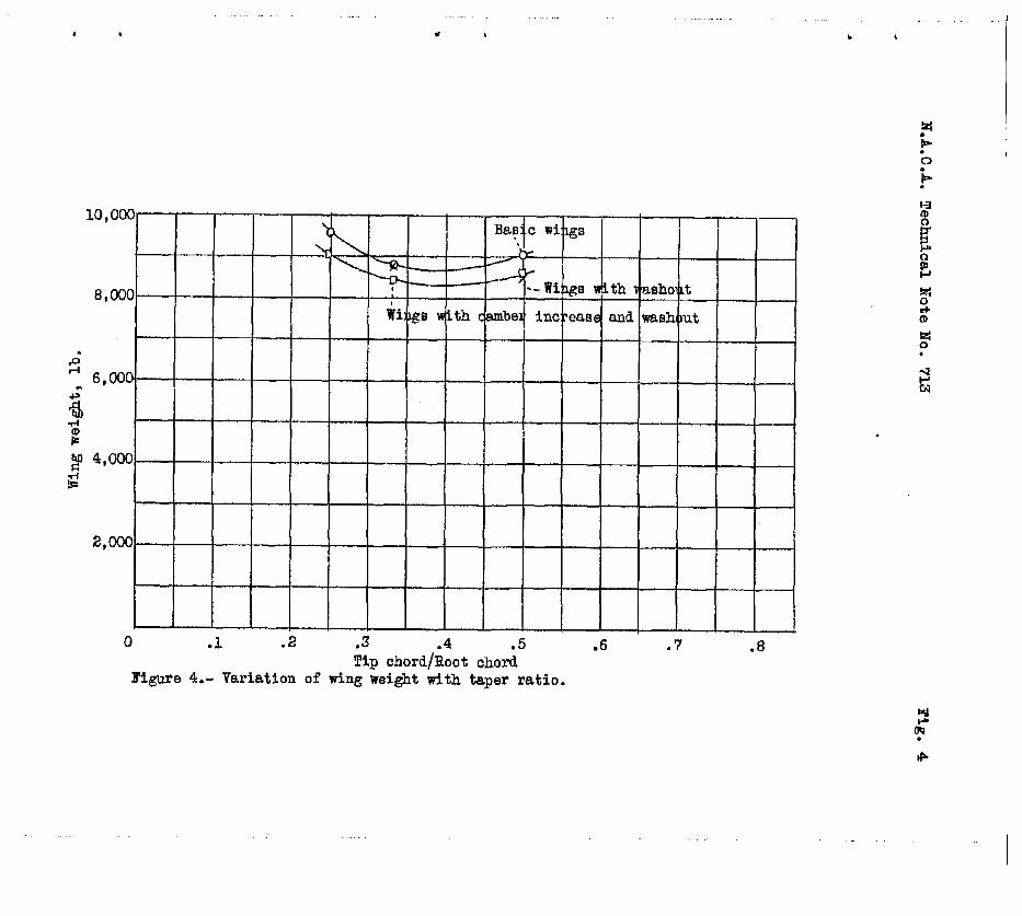
With reference to the weights of the wings, it may be' noted that the lowest weights were obtained for the wings with camber increase and washout. The lowest weight is fn- dicated for a taper ratio between l/2 and l/3, as may be seen from ffgure 4. In order to determine whether the low- est-weight had been approaahed, the case of taper ratio l/3 with washout, and camber increase qas investigated with twice as much kashout, or 4O. The fncrea.se in washout re- quired a reduction in thickness to obtain the desired drag at cruising speed and an increase in qia.n to -maintain the desired induced drag at low speed. The result tvas a con- siderable increase is woight.
If this analysts were applied to wings of other size, % max
and Do would be affected by the change in .Reynolds Number, but ,it is believed that considerable variation in skze would be possfble without altering the conclusion as to the best tap'er ratio. The number of engines is alsO Of
14 M.A.C..A. Technical Note Bo. 713
slight importance because the efiect of their relieving load on the wing weight is small. It is also believed that, for .the thickness ratios in common use, the selec- tion of a different thickness ratio for the basic wing would not appreciably alter the conclusions.
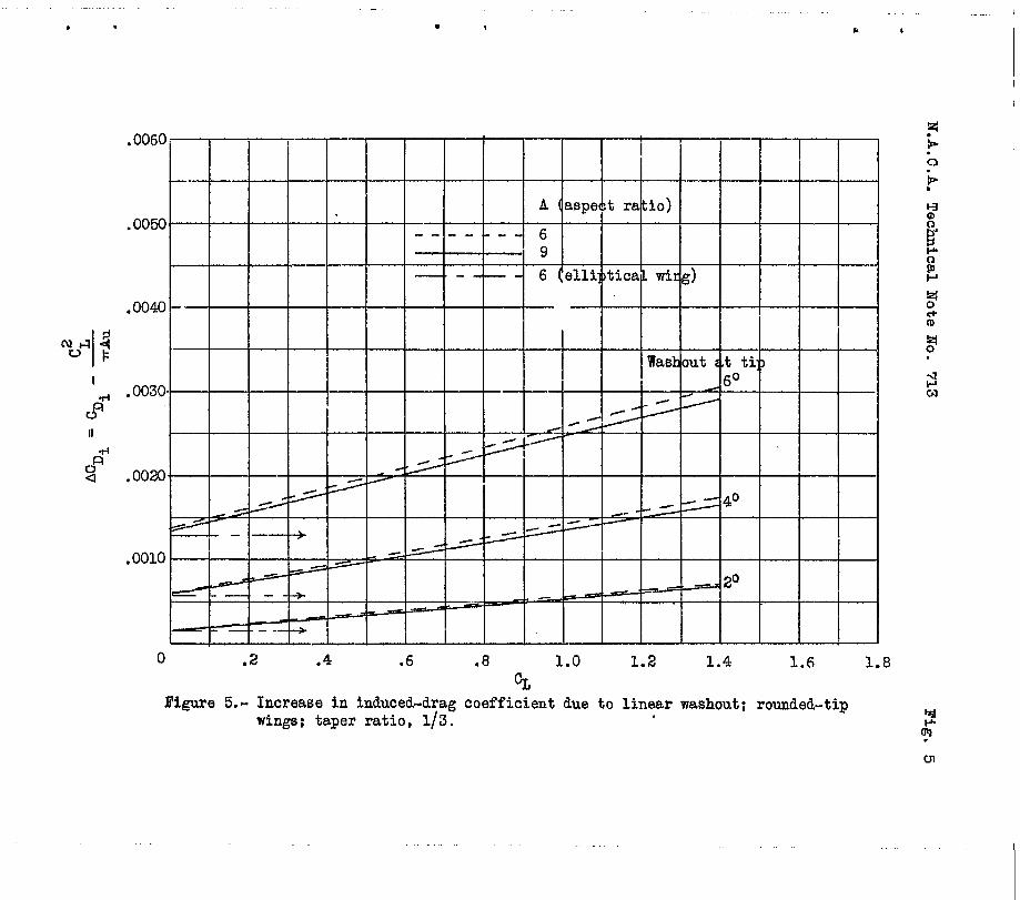
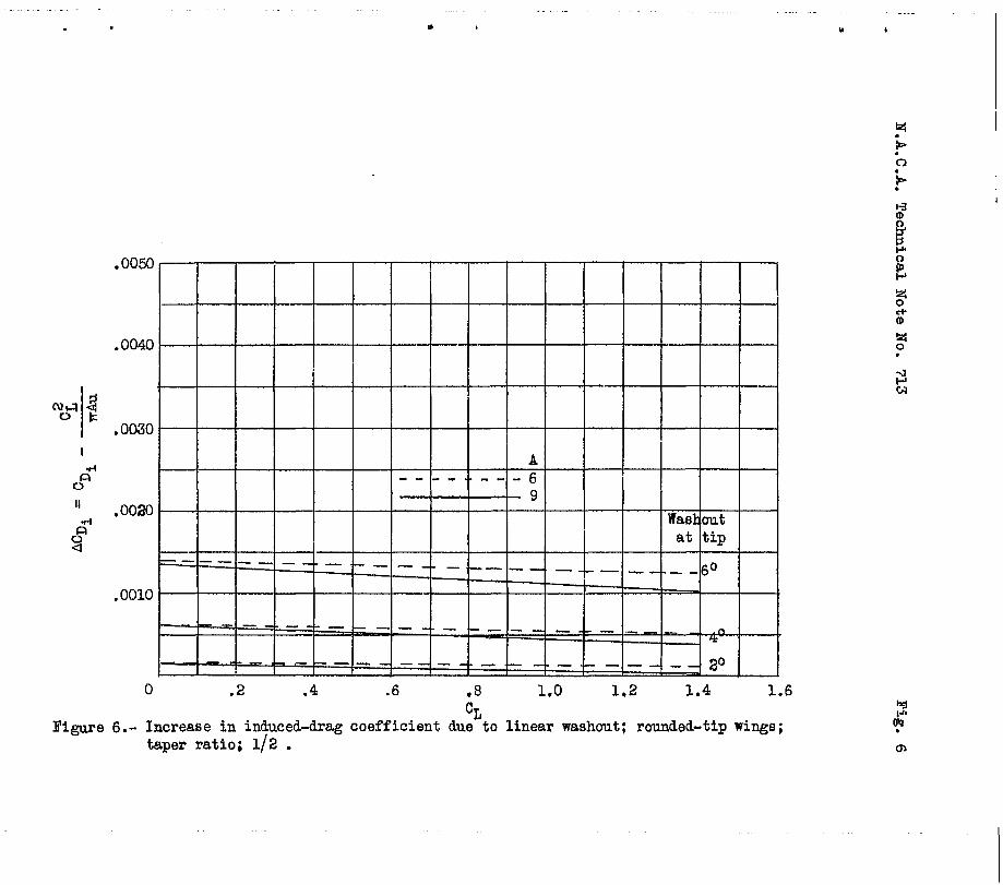
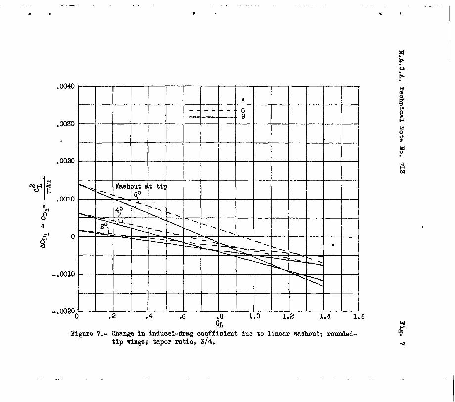
As an aid fn similar calculatfons and to show the ef- fect of washout on CDi* the'change in CD1 due to wash- out has been plotted in figures 5 to 7. The increase fn
% may be considered to consist of two parts, whfch may
bb found by dividing the last'tmo terms of equation (1) by qs- The w(c aoF term is the increase in % for CD = 0 and varies mainly with c2, as T does not vary much in the usual range of taper ratios. (See fig. 6 of ref- erence 4,) The term Q c ao CD contributes a positive or a negative increment depending on the sign of v except that, for the elliptical wing, v = 0 and ACDi does not vary with CD. For the tapered wings, however, in- creases with CD for taper ratios less than about as may be seen from ffgures 5 to 7.
For taper ratios approaching 1, aCDi become 6 nega- tive for high values of CD as shown by figure 7, which means that an elliptical span loading is approached owing to the washout. Values. of ACDi for other aspect ratios and taper ratios,. for either washin or washout, may be cab culated from reference 4.
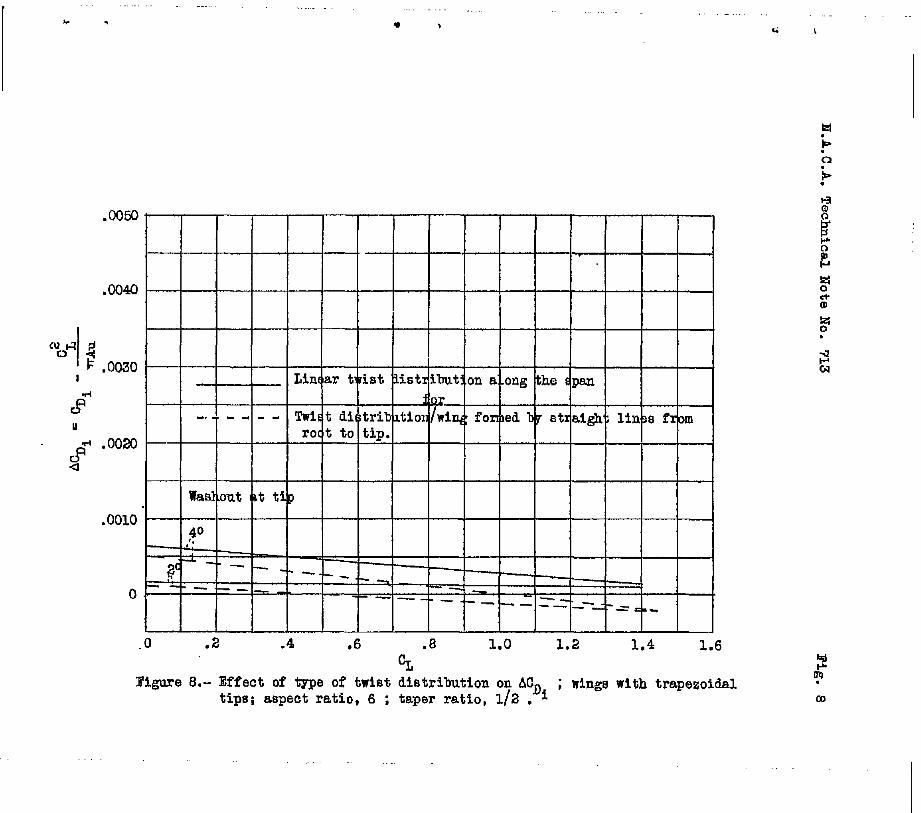
The values of ACDI given are for wings with linear t.wist distr,ibution al,ong the span. Wings are commonly constructed using straight-line element's between corre- spon'ding points of the root and the tip sections. For such a construction, the twist distribution is nonlinear and, for a given washout at the tip, ACDp is less than for a. linear twist distribution. As an illustration of the order of magnitude of the difference *hat. the type of twist dis- tribution may produce, values of ACDi are given in fig- ure 8 for wings with trapezoidal tips and with th'e two types of twist distribution. As may be seen, the dfffar- once's are small. Vith reference to the effect of the type of twist distribution on the lift distribution, and hence on the margin against stalling of the tips, itmay be said that the amount of washout required is substantially tha
N.A.G.A. Technical Hoto Na.. 713 15
same for the two tmes of twist distribution for taper ratios between l/3 and 1.0. .
From the present paper and from the data given in reference 4, similar calculations can be made for wings of any size and for any aerodynamic conditions. Analyses should probably be made for wings with partial-span flaps and other high-lift devices.
CONCLUSIONS
For wings within the range of thickness ratios Corn- manly used, designed to be aerodynamically equal, and with. tip stalling avoided by the methods considered, the re- sults of this analysis indicate that:
1. The optimum wings (the wings of the lowest weight) are obtained when tip.stalling is prevented by the use of moderate washout combined with an increase in camber of the airfoil sections from the center to the tip.
2. and l/3.
The optimum wings have a taper ratio between l/2 ,
Langley Memorial Aeronautical Laboratory, National Advisory Committee for Aeronautics,
Langley Field, Va., May 3, 1939.
16 P.A.C,A; Technical vote NO, '713
APPENDIX -
Symbols
St wing,area.
b, span.
%I 9 span cf basic wbg.
A, aspect ratfo, lJ=/s.
ct chord at any section along the span.
et aerodynamic twist; in degrees, from root to tip, measured between the eera-lift directions of the center and the tip sections, negative for washout.
Yt distance along the span measured from the center.
YpY1 ‘Ya s- see figure 3.
&01 section lfft-curve slope, per degree.
c’G ’ section 11ft coefficient: cl = ct a + Cl .
b
=tb* part of lift coefficient due to aerodynamic
twist (computed 'for CD = 0); ~1% = % Lb.
Ct ' a part of lift coefficfent due to angle of attack at any CL; cl
a = % clale
c’1a,’ part of lift coefficient due to angle of attack for CL = 1.0; cl
81 =cb ' La*
&fib, additional and basic load distribution parameters. (Values of La and LJ., were taken from rsf- erence 4 to obtain the load distributions.)
=t max' airfoil section maximum lift coefffcient.
cao ’ airfofl section profile-drag coefficient. .
N.A.C.A, Technical Mote No. 713 17
wfng normal-force coe?ficient (taken equal to CL).
wing lift coefficient.
wing maximum lift coefficfent.
wfng profile-drag coefficient.
wing induced-drag coefficient.
increa,se dn wing Induced-drag coefficient due to aerodynamic twist;'
total wing drag.
wing profile drag?
wing induced drag.
induced drag of the basic wing. .
tnduced-drag factors (reference 4).
limft-load factor.
lo&d distribution per unit length along the span l
. .
aiihlane gross wefght. ', - . wing weight. . . . . . . . . Subscripts W, F, and C refer to web, flange,
and cover neiqhts,'reBpectivgly. ' .
A refers to a weight decrement due to relieving loads.
FS, shear force at any point along the span.
MS bending moment at ahy point along the,span*
P, specific'meight (of aluminum alloy, 0.1 lb./ cum in.).
8, allowable stress, t's effective thickness of beam at any point along
span. tst* effective thickness of beam at center of wing.
18
1.
2.
3.
4.
5.
6.
7.
0.
N .A :O .A.
. . . ;‘.’
Technical Note No. 713
REFERENTCES
Upson, Ralph H.: Wings - A Coordinated System of Basic Design. S.A.E. Jour., vol. XXVI, no. l,.Jan. 1930, PP. 15-30.
Upson, R. H., and Thompson, M. J.: The Drag of Tapered Cantilever Afrfoils. Jour. Aero. Scf., VOL. 1, no. 4, Oct. 1934, pp. 168-177.
Lachmann, 0. V.: .A,erodynamic and Structural Features of Tapered Wings. R.A.S. Jour., vol. XLI, no. 315, March 1937, pp. 162-212.
Anderson, Raymond F.: Determination of the Character- istics of Tapered Wings. T.R. No. 572, N.A.C.A., 1936.
Jacobs, Eastman N., Pinkerton, Robert Ma, and.Greenberg, Harry: Tests of Related Forward-camber Airfoils in the Varfable-Density Wind Tunnel. T.R. No. 610, N.A.C.A., 1937.
Anderson, Raymond F.: The Experimental and Calculated Characteristics of 22 Tapered Wings. T.R. No. 627, N.A.C.A., 1938.
Jacobs, Eastman N., and Abbott, Ira H.: Airfoil Sec- tion Data Obtained in the N.h.C.A, Variable-Density Tunnel as Affected by Support Interference and Other Corrections. T-.B. No, 66'9, N.A.C.A., 1939.
Burr Ai& Commerce, U. S. Dept. Commerce: Airplane Air- worthiness. Pt. 04 of Civil Air Regulations, May 1938, ppa 12 f383 and 69 1851.
,
TASLE I - S-Y OF RESUIDS
6 .
center stall obtained by -
1eadinlS edge .
Waehout, camber increase, and sharp leading edge Center etaI. obtained b -
Papel ratic
drea S
,sq.ft
Boot Tip 'chord,
(Z.)
SP= b
(ft.)
138.0 138.2 x38.5
SB00t sirfoil Bectian ti.A.C!.A.
23015.4 23014 23gll
Tip airfoil section 19.A.C.A
*Cl
20.91 10.46 24.20 8.07 27.29 6.82
'.23CQ9 23009
22ioo9 23009
0.16 .36 .43
kerodpami waehout at tips
(deg-1
0 0 0
X58.1 20.46 10.24 K?ms.s 138.8 23.89 7.96 23013A
- 2 1
138.0 x39.2 140.2
20.40 22.55 24.62
10.20 7.52 6.16
23016 33014 33012 3ections Wight o flans-,
-.. 433009 43009
ith shai lsadiw Aeight a :overiLlg
and mbcing
~~~
2;6l4 2,790
1 2 2
i&33*1
Limit- load factor,
weight of web Total
veight
Il.
0.309 30.6 2.98 ,300 29.1 3.C4 .ml 27.2 a.15
yi=Zf 5,930 5,572 6,202
624 616 607
-&c- 8:601 9,599
.316 30.6 2.93 6,465 583 2,46l 8,528
.3OO 29.2 3.03 6,&6 592 2,606 8,6S4
.317 30.7 a.91 5,521 599 2,474 8,594
.a17 30.a 2.93 5,395 568 2,47C 8,433
.307 29.8 2.98 5,904 565 2,551 9,020
Aspec ratio
A
0 113 li4
l/2 113
112 l/3 114
2,132 2,200 2,350
2,090 2,194
2,oe2 2,080 2,149
8.93 8.6E 8.U
9.13 8.77
9.15 9.3a 9.16
Do/9 Q/s D/q
is-7 12.8 12.7
7.4 7.4 7.4
12.6 7.6 l.2.6 7.5
12.7 12.4 12.3
7.4 7.8 7.9
ShatI, leadIng em Washout and harp l@ling edge Waahont , camber increaee, and vbarp $,"'"
--- I
. L l , r ,
1.6 r - -
I I I I I i
3 -.w
0 .2 .4
----r-m--. I- I I I
kargin ’ - -- 1 = .l z
-
Root Fraction of semispan, . -7- b2 Tip
Figure 2.- Calculated stall of ring with camber increase and washout; taper ratio, l/3. -
H.A.C.A. Technical Xote No. 713 Ffg. 3
y2 ------I
b/2 D
Figure 3.- Spar structure and loads on ming.
. . ,
0 .l .2 .3 .4 .5 .6 .7 Tip chord/Root chord
.8
mgwe 4.- Variation of wing weight with taper ratio.
. ‘ ,
.0060. I
.0050 A (aspect ratio)
..,-..--w- 6 ’ 9
.0040-
- 6 (elli:,tica., wing)
I
Waskout g.t tg?
. ooxb //-
%- /c fi/ -- I
2
0 .2 .4 .6 .8 1.0 1.2 1.4 1.6 1.8 cr,
Figllre 5.- Increase in induced-drag coefficient due to linear washout; rounded-tip wings; taper ratio, l/3.
. 0010
‘4 6 cn
. I * ,
.0050
.0040
l 0030
.0020
. 0010
0 .2 .4 .6 .8 1.0 1.2 1.4 1.6
-
-
-
--
-
-
-
-
-
-
-
CL Figure 6.- Increase in induced-drag coefficient due to linear washout; rounded-tip wings;
taper ratio; l/2 .
- l . .
“s-’ f! I I
,i: n
CG a 0
,.oolO
I I I I I I I I .2 .4 .6 1.0 1.2 1.4 1 1.6
pigare 7.” w in inhc~&drag coefficient due to linear washout: rounded- tip wlnga; taper ratio, 314.
* . . >
- - -- - __ ---
-0 .2 2% .6 .8 1.0 1.2 1.4 1.6
li L
mgure cl.- Effect of tppe of twist distrfbution on CL% ; wings with trapezoidal. tips; aspect ratio, 6 ; taper ratio, l/S , i
J ma . m