Embed Size (px)
Citation preview

Egon von RuvillE gmbH
Billbrookdeich 112 • 22113 Hamburg • Germany
Phone: +49 (0)40 73344 - 0 • Fax: +49 (0)40 73344 - 199
[email protected] • www.ruville.de 75/0
85 R
431/
1.0/
1.20
11/M
A-G
B
TECHNICAL BROCHURE:
CV JOINTS
MOTOR | CHASSIS | SERVICEExpERTISE IN CAR pARTS

Technical brochure: CV joints 2 | 3
Nowadays, front-wheel and most rear-wheel drive vehicles
have two side shafts that each consist of a fixed shaft with
two CF joints at the ends. The side shafts permit vibration-
free, constant drive of the individual wheels. The shorter
the distance between the drive point (engine/gearbox) and
the output point (wheel), the lower the energy loss.
The core task of the CV joints consists in low-friction transfer
of the torque from the gearbox to the wheel, compensating
for deflection in the chassis, and also for steering movements
in front-wheel drive vehicles. The degrees of freedom needed
for steering and deflection are provided by the bending angle
and axial displacement of the joints. To this end, each side
shaft needs a plunging and a fixed joint.
1. HOW CV JOINTS WORK
1. How CV joints work 3
2. Typification of CV joints and their structure 4
2.1 Fixed joints 4
2.2 plunging joints 4
2.2.1 plunging ball joints 4
2.2.2 plunging tripod joints 5
2.2.3 Circular plunging tripod joints 6
2.2.4 DO plunging joints (double offset joint) 6
3. Service life of CV joints depending on ambient conditions 7
4. possible causes of damage to side shafts and CV joints 8
4.1 Damage to fixed joints 8
4.2 Damage to plunging joints 8
4.2.1 Damage to plunging ball joints 10
4.2.2 Damage to circular plunging tripod joints 10
4.2.3 Damage to DO plunging joints 11
4.3 Damage to the axle boot 11
5. Lubricant 12
5.1 Molybdenum disulphide as lubricant for CV joints 12
5.2 Why is molybdenum disulphide called grease? 13
6. Recommendations 14
7. Troubleshooting 15
CONTENTS
Tripod joint
Wheel joint kit
Wheel joint

Technical brochure: CV joints 4 | 5
a
b
c 1
2
34
2.1 Fixed joints
The name is derived from the function: The pivot of the shaft
is not changeable, thus facilitating rotation. Fixed joints do
not permit any axial movement. As a rule, they are used in
front-wheel drive vehicles at the wheel end of the side
shafts, permitting bending angles of up to 53° depending
on the vehicle type.
Component parts:
1. Housing
2. Cage
3. Balls
4. Core
5. Axle boot
2.2 plunging joints
They permit both angular movement and axial movement,
and are available in the following different types:
2.2.1 plunging joints
Also referred to as “VL”-type joints because of the
V-shaped design of the raceways on the inside of
the joint.
The ball raceways are straight.
Bending angles of up to 22° are possible.
The plunging distance is approx. 48 mm.
Good torque transmission is ensured even at
high speeds.
In front-wheel drive vehicles, they are only fitted to
the gearbox side. In rear-wheel drive vehicles,
plunging ball joints can be used at both ends of
the side shaft.
Component parts:
1. Outer raceway
2. Cage
3. Balls
4. Core
5. Axle boot
2. TypIFICATION OF CV JOINTS AND THEIR STRUCTURE
3
2
1
45
3
1
42
5
2.2.2 plunging tripod joints
Are fitted to the gearbox side, attenuating the transmission
of engine vibrations by up to 65 %. Therefore they are
mainly fitted to vehicles with diesel engines and often
together with automatic gearboxes. This also safeguards
an uninterrupted flow of power to the wheels. Plunging
tripod joints have less friction between the component
parts and permit changes in length of the side shaft.
Bending angles of up to 18° are possible.
The plunging distance is approx. 55 mm.
The tripod joint has three stubs, with needle bearings
connecting them to the outer rollers. The raceways of
the outer rollers move in linear fashion in each of the
inner raceways of the housing or “bell”.
The needle bearings of the outer rollers of the tripod joint
perform various tasks. In addition to low-friction compen-
sation for the length of the side shaft, they have to transmit
the drive forces from the gearbox to the side shaft.
Component parts:
1. Tripod joint
a) Bearing surface
b) Needles
c) Retainer
2. Bell
3. Straight raceway
4. Axle boot

Technical brochure: CV joints 6 | 7
3. SERVICE LIFE OF CV JOINTS DEpENDING ON AMBIENT CONDITIONS
The service life of CV joints primarily depends on the
conditions in which the vehicle is being operated. Damage
to a joint can have severe consequences, with loss of
traction force in the most favourable case. In the worst
case, a wheel can block or the side shaft itself works
loose. It is no rarity for such situations to result in damages
to surrounding parts such as gearbox, oil sump etc.
Problems in CV joints are revealed by vibrations and
noises while driving. It is advisable to have the vehicle
checked by an expert at a garage at the smallest sign of
any discrepancy.
80% of the problems in CV joints are caused by a change
in the working distance of the side shaft, 8 % by faults or
negligence during installation. 8 % come from cracked
axle boots which lead to a loss of lubricant, resulting in
soiling of the joint. Only the remaining 4% of all joint failures
have been caused by jolts and normal wear and tear of
the parts.
In many cases where side shafts are damaged, the cause
is not eliminated during the first visit to the garage. The
actual problem is still present and reoccurs repeatedly
to the customer’s dissatisfaction.
Correct alignment of the unit consisting of engine, gear-
box and wheel suspension makes an important contri-
bution to the durability and long service life of joints and
side shafts. CV joints normally have a long service life.
But this can only be safeguarded by regularly checking
that the axle boots do not leak and that the clamps fit
firmly.
If the engine and/or gearbox have to be removed as a
result of an accident or repairs to the units, it is important
to ensure that the unit assembly is correctly centred
when subsequently fitting it back into the vehicle. The
fastening points of the beams have corresponding
tolerances to achieve correct alignment.
When work is being carried out to the steering trapeze, it
is extremely important to achieve a 100 % setting of the
toe difference angle and the maximum steering angle. If
the maximum steering angle is outside the bending angle
of the joint, there is a risk of destroying the joint. In axles
designed to use the end stops of the steering angle, these
also have to be checked for signs of wear and tear or
damage.
2.2.3 Circular plunging tripod joints
Ideal for use on the gearbox side in small vans and sports
cars. Three independent rollers are placed on the stubs
of the tripod joint, moving within groove-shaped race-
ways as in conventional plunging tripod joints. The stubs
of the tripod joint are circular in shape so that the rollers
can move on the tripod joint like a pendulum bearing.
This achieves a smooth drive while attenuating jolts and
vibrations in torque transmission by up to 70%.
Circular plunging tripod joints are suitable for transmitting
high torques.
Bending angles of up to 18° are possible.
The plunging distance is approx. 40 mm.
Component parts:
1. Straight raceway
2. Rollers
3. Tripod joint
4. Axle boot
2.2.4 DO plunging joints (double offset joint)
Fitted to the gearbox side of those front-wheel drive
vehicles with limited space. The design is pin-shaped
and consists of a combination of the plunging
ball joint and the plunging tripod joint.
DO plunging joints have straight raceways.
Bending angles of up to 22° are possible.
The plunging distance is approx. 55 mm.
Component parts:
1. Straight raceway
2. Cage
3. Balls
4. Core
5. Axle boot
1 3
24
5
1
4
3
2

Technical brochure: CV joints 8 | 9
The working distance of the side shaft is stipulated by
the design. Any corresponding changes caused by outer
influences can result in severe damage. The necessary
working distance is mainly changed by the following
influences:
1. Engine and/or gearbox support
2. Centre alignment of engine and gearbox
3. Discrepancies in the wheel suspension
(damage to the hubs, steering knuckles,
joints, shock absorbers, etc.)
4.1 Damage to fixed joints
As a rule, it is the joint on the gearbox side that will be
damaged first by overload on the side shaft.
Excessive vibrations and jolts are also transmitted to the
outer joint, thus causing cracks to the inner component
parts of the joint.
Most joint failures are caused by defective or torn axle
boots. The outer joint is frequently affected in this case, as
the larger bending angle places more of a load on the axle
boot.
4. pOSSIBLE CAUSES OF DAMAGE TO SIDE SHAFTS AND CV JOINTS
Load in daily operation (change in angle and length)
Strain from changes in the working distance (caused by worn engine bearing and gearbox bearing, incorrect centre alignment of engine and gearbox)
Engine support
Gearbox support Worn chassis or steering knuckle
Technical brochure: CV joints 10 | 11
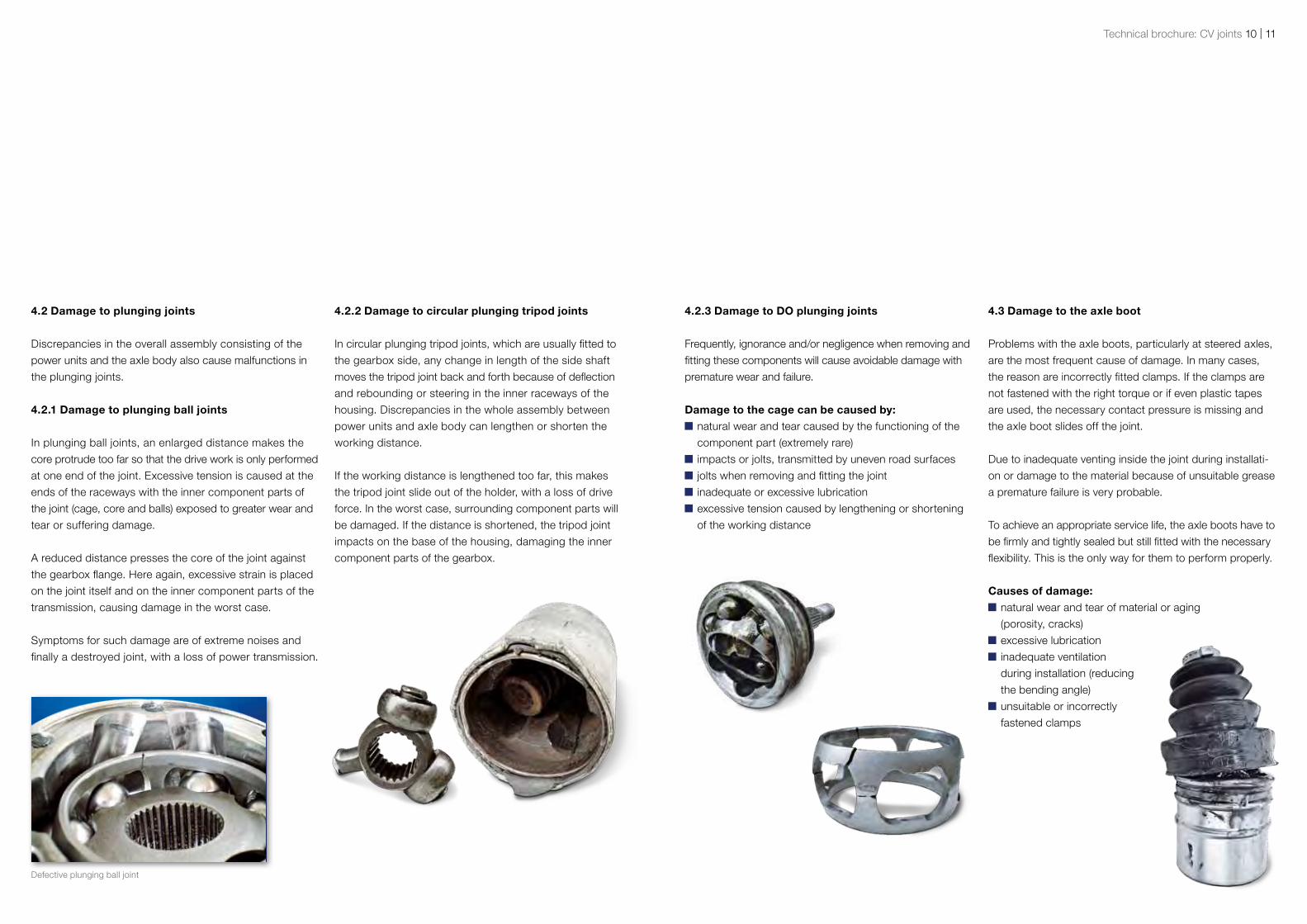
4.3 Damage to the axle boot
Problems with the axle boots, particularly at steered axles,
are the most frequent cause of damage. In many cases,
the reason are incorrectly fitted clamps. If the clamps are
not fastened with the right torque or if even plastic tapes
are used, the necessary contact pressure is missing and
the axle boot slides off the joint.
Due to inadequate venting inside the joint during installati-
on or damage to the material because of unsuitable grease
a premature failure is very probable.
To achieve an appropriate service life, the axle boots have to
be firmly and tightly sealed but still fitted with the necessary
flexibility. This is the only way for them to perform properly.
Causes of damage: natural wear and tear of material or aging
(porosity, cracks)
excessive lubrication
inadequate ventilation
during installation (reducing
the bending angle)
unsuitable or incorrectly
fastened clamps
4.2.3 Damage to DO plunging joints
Frequently, ignorance and/or negligence when removing and
fitting these components will cause avoidable damage with
premature wear and failure.
Damage to the cage can be caused by: natural wear and tear caused by the functioning of the
component part (extremely rare)
impacts or jolts, transmitted by uneven road surfaces
jolts when removing and fitting the joint
inadequate or excessive lubrication
excessive tension caused by lengthening or shortening
of the working distance
4.2.2 Damage to circular plunging tripod joints
In circular plunging tripod joints, which are usually fitted to
the gearbox side, any change in length of the side shaft
moves the tripod joint back and forth because of deflection
and rebounding or steering in the inner raceways of the
housing. Discrepancies in the whole assembly between
power units and axle body can lengthen or shorten the
working distance.
If the working distance is lengthened too far, this makes
the tripod joint slide out of the holder, with a loss of drive
force. In the worst case, surrounding component parts will
be damaged. If the distance is shortened, the tripod joint
impacts on the base of the housing, damaging the inner
component parts of the gearbox.
4.2 Damage to plunging joints
Discrepancies in the overall assembly consisting of the
power units and the axle body also cause malfunctions in
the plunging joints.
4.2.1 Damage to plunging ball joints
In plunging ball joints, an enlarged distance makes the
core protrude too far so that the drive work is only performed
at one end of the joint. Excessive tension is caused at the
ends of the raceways with the inner component parts of
the joint (cage, core and balls) exposed to greater wear and
tear or suffering damage.
A reduced distance presses the core of the joint against
the gearbox flange. Here again, excessive strain is placed
on the joint itself and on the inner component parts of the
transmission, causing damage in the worst case.
Symptoms for such damage are of extreme noises and
finally a destroyed joint, with a loss of power transmission.
Defective plunging ball joint

Technikbroschüre Gleichlaufgelenke 12 | 13Technical brochure: CV joints 12 | 13
Any cracks or leaky axle boots will result in a loss of
lubricant while dirt penetrates the joint. Inadequate or
excessive lubrication or even unsuitable lubricants cause
premature wear and tear of the inner component parts.
5.1 Molybdenum sulphide as lubricant for CV joints
Grease is not suitable as a lubricant in certain cases. This
applies particularly to CV joints. Contrary to common
opinion, CV joints are lubricated with oil and not grease.
Oil is used in situations where high temperatures can be
caused by the surroundings, high revs, high loads or
constant friction of the inner component parts. All these
factors come together in CV joints. For this reason, lubrication
must be constant and take place in a suitable manner. The
rotating components and raceways do not have a smooth
surface, as it appears at first glance. A look through the
microscope reveals a complete irregular surface.
To avoid direct contact between the two surfaces, those
lubricants are used which form a thin lubricating film. Oil,
with its special properties, is particularly suited in this case.
5. LUBRICANT
5.2 Why is molybdenum sulphide called grease?
The high loads occurring in CV joints demand resistant
lubrication of the joint. A thin oil film cannot withstand
these loads and would soon be displaced. Due to the
structure of solid additives such as molybdenum sulphide
they cannot be simply displaced and therefore represent,
in combination with oil, the ideal lubricant. In this way,
“lubricating rails” are formed between the surfaces, thus
considerably improving the lubricating properties.
Molybdenum sulphide is a “polar” additive. In other words,
its polarised molecules align themselves vertically to the
metal surface, thus forming a more resistant lubricating
film.
Metal surface
Metal surface
Lubricating film between friction partners
Technical brochure: CV joints 14 | 15
7 8
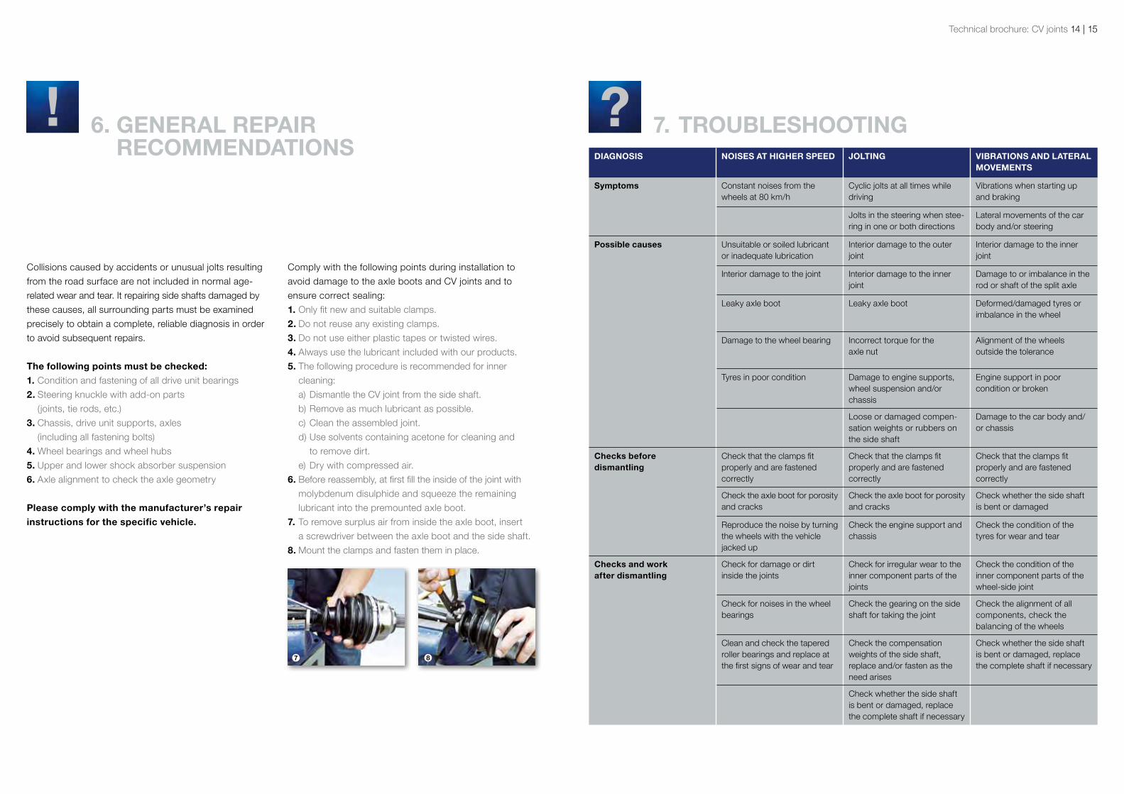
DIAGNOSIS NOISES AT HIGHER SpEED JOLTING VIBRATIONS AND LATERAL MOVEMENTS
Symptoms Constant noises from the wheels at 80 km/h
Cyclic jolts at all times while driving
Vibrations when starting up and braking
Jolts in the steering when stee-ring in one or both directions
Lateral movements of the car body and/or steering
possible causes Unsuitable or soiled lubricant or inadequate lubrication
Interior damage to the outer joint
Interior damage to the inner joint
Interior damage to the joint Interior damage to the inner joint
Damage to or imbalance in the rod or shaft of the split axle
Leaky axle boot Leaky axle boot Deformed/damaged tyres or imbalance in the wheel
Damage to the wheel bearing Incorrect torque for the axle nut
Alignment of the wheels outside the tolerance
Tyres in poor condition Damage to engine supports, wheel suspension and/or chassis
Engine support in poor condition or broken
Loose or damaged compen-sation weights or rubbers on the side shaft
Damage to the car body and/or chassis
Checks before dismantling
Check that the clamps fit properly and are fastened correctly
Check that the clamps fit properly and are fastened correctly
Check that the clamps fit properly and are fastened correctly
Check the axle boot for porosity and cracks
Check the axle boot for porosity and cracks
Check whether the side shaft is bent or damaged
Reproduce the noise by turning the wheels with the vehicle jacked up
Check the engine support and chassis
Check the condition of the tyres for wear and tear
Checks and work after dismantling
Check for damage or dirt inside the joints
Check for irregular wear to the inner component parts of the joints
Check the condition of the inner component parts of the wheel-side joint
Check for noises in the wheel bearings
Check the gearing on the side shaft for taking the joint
Check the alignment of all components, check the balancing of the wheels
Clean and check the tapered roller bearings and replace at the first signs of wear and tear
Check the compensation weights of the side shaft, replace and/or fasten as the need arises
Check whether the side shaft is bent or damaged, replace the complete shaft if necessary
Check whether the side shaft is bent or damaged, replace the complete shaft if necessary
6. GENERAL REpAIR RECOMMENDATIONS
Collisions caused by accidents or unusual jolts resulting
from the road surface are not included in normal age-
related wear and tear. It repairing side shafts damaged by
these causes, all surrounding parts must be examined
precisely to obtain a complete, reliable diagnosis in order
to avoid subsequent repairs.
The following points must be checked:1. Condition and fastening of all drive unit bearings
2. Steering knuckle with add-on parts
(joints, tie rods, etc.)
3. Chassis, drive unit supports, axles
(including all fastening bolts)
4. Wheel bearings and wheel hubs
5. Upper and lower shock absorber suspension
6. Axle alignment to check the axle geometry
please comply with the manufacturer’s repair instructions for the specific vehicle.
Comply with the following points during installation to
avoid damage to the axle boots and CV joints and to
ensure correct sealing:
1. Only fit new and suitable clamps.
2. Do not reuse any existing clamps.
3. Do not use either plastic tapes or twisted wires.
4. Always use the lubricant included with our products.
5. The following procedure is recommended for inner
cleaning:
a) Dismantle the CV joint from the side shaft.
b) Remove as much lubricant as possible.
c) Clean the assembled joint.
d) Use solvents containing acetone for cleaning and
to remove dirt.
e) Dry with compressed air.
6. Before reassembly, at first fill the inside of the joint with
molybdenum disulphide and squeeze the remaining
lubricant into the premounted axle boot.
7. To remove surplus air from inside the axle boot, insert
a screwdriver between the axle boot and the side shaft.
8. Mount the clamps and fasten them in place.
7. TROUBLESHOOTING

Egon von RuvillE gmbH
Billbrookdeich 112 • 22113 Hamburg • Germany
Phone: +49 (0)40 73344 - 0 • Fax: +49 (0)40 73344 - 199
[email protected] • www.ruville.de 75/0
85 R
431/
1.0/
1.20
11/M
A-G
B
TECHNICAL BROCHURE:
CV JOINTS
MOTOR | CHASSIS | SERVICEExpERTISE IN CAR pARTS