Embed Size (px)
Citation preview
Working Paper Series Congressional Budget Office
Washington, D.C.
Technical Challenges of the U.S. Army’s Ground Combat Vehicle Program
Bernard Kempinski National Security Division
Congressional Budget Office ([email protected])
Christopher Murphy National Security Division
Congressional Budget Office ([email protected])
November 2012
Working Paper 2012-15
To enhance the transparency of the work of the Congressional Budget Office (CBO) and to encourage external review of that work, CBO’s working paper series includes both papers that provide technical descriptions of official CBO analyses and papers that represent independent research by CBO analysts. Working papers are not subject to CBO’s regular review and editing process. Papers in this series are available at http://go.usa.gov/ULE.

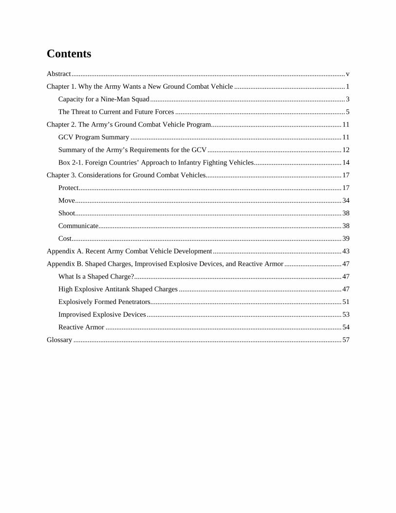
Contents Abstract ......................................................................................................................................................... v
Chapter 1. Why the Army Wants a New Ground Combat Vehicle .............................................................. 1
Capacity for a Nine-Man Squad ............................................................................................................. 3
The Threat to Current and Future Forces ............................................................................................... 5
Chapter 2. The Army’s Ground Combat Vehicle Program ......................................................................... 11
GCV Program Summary ...................................................................................................................... 11
Summary of the Army’s Requirements for the GCV ........................................................................... 12
Box 2-1. Foreign Countries’ Approach to Infantry Fighting Vehicles ................................................. 14
Chapter 3. Considerations for Ground Combat Vehicles............................................................................ 17
Protect ................................................................................................................................................... 17
Move ..................................................................................................................................................... 34
Shoot ..................................................................................................................................................... 38
Communicate ........................................................................................................................................ 38
Cost ....................................................................................................................................................... 39
Appendix A. Recent Army Combat Vehicle Development ........................................................................ 43
Appendix B. Shaped Charges, Improvised Explosive Devices, and Reactive Armor ................................ 47
What Is a Shaped Charge? .................................................................................................................... 47
High Explosive Antitank Shaped Charges ........................................................................................... 47
Explosively Formed Penetrators ........................................................................................................... 51
Improvised Explosive Devices ............................................................................................................. 53
Reactive Armor .................................................................................................................................... 54
Glossary ...................................................................................................................................................... 57
iv
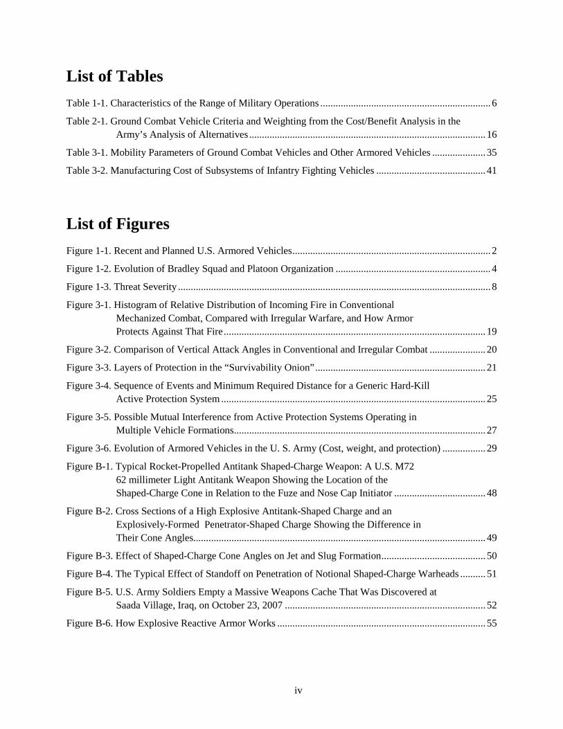
List of Tables Table 1-1. Characteristics of the Range of Military Operations ................................................................... 6
Table 2-1. Ground Combat Vehicle Criteria and Weighting from the Cost/Benefit Analysis in the Army’s Analysis of Alternatives ............................................................................................. 16
Table 3-1. Mobility Parameters of Ground Combat Vehicles and Other Armored Vehicles ..................... 35
Table 3-2. Manufacturing Cost of Subsystems of Infantry Fighting Vehicles ........................................... 41
List of Figures Figure 1-1. Recent and Planned U.S. Armored Vehicles .............................................................................. 2
Figure 1-2. Evolution of Bradley Squad and Platoon Organization ............................................................. 4
Figure 1-3. Threat Severity ........................................................................................................................... 8
Figure 3-1. Histogram of Relative Distribution of Incoming Fire in Conventional Mechanized Combat, Compared with Irregular Warfare, and How Armor Protects Against That Fire ....................................................................................................... 19
Figure 3-2. Comparison of Vertical Attack Angles in Conventional and Irregular Combat ...................... 20
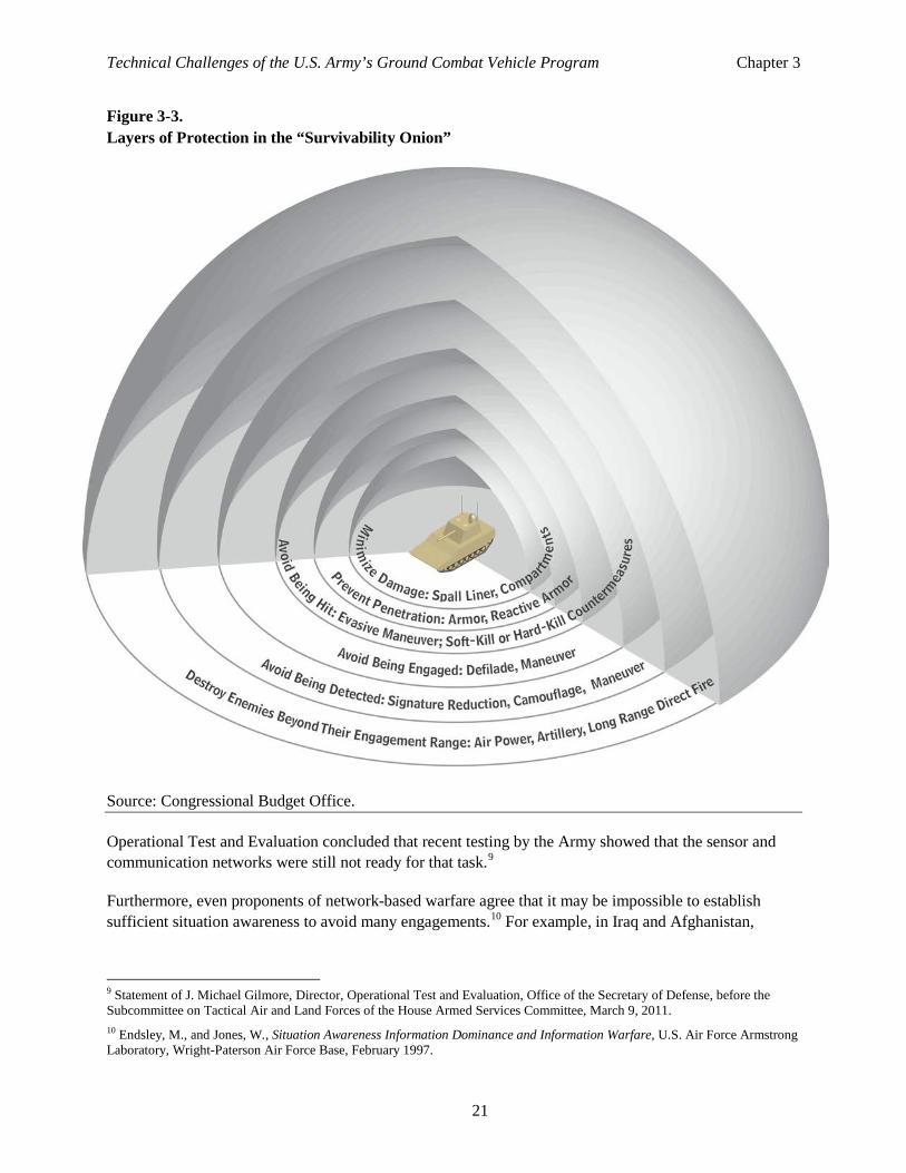
Figure 3-3. Layers of Protection in the “Survivability Onion” ................................................................... 21
Figure 3-4. Sequence of Events and Minimum Required Distance for a Generic Hard-Kill Active Protection System ........................................................................................................ 25
Figure 3-5. Possible Mutual Interference from Active Protection Systems Operating in Multiple Vehicle Formations ................................................................................................... 27
Figure 3-6. Evolution of Armored Vehicles in the U. S. Army (Cost, weight, and protection) ................. 29
Figure B-1. Typical Rocket-Propelled Antitank Shaped-Charge Weapon: A U.S. M72 62 millimeter Light Antitank Weapon Showing the Location of the Shaped-Charge Cone in Relation to the Fuze and Nose Cap Initiator .................................... 48
Figure B-2. Cross Sections of a High Explosive Antitank-Shaped Charge and an Explosively-Formed Penetrator-Shaped Charge Showing the Difference in Their Cone Angles................................................................................................................... 49
Figure B-3. Effect of Shaped-Charge Cone Angles on Jet and Slug Formation ......................................... 50
Figure B-4. The Typical Effect of Standoff on Penetration of Notional Shaped-Charge Warheads .......... 51
Figure B-5. U.S. Army Soldiers Empty a Massive Weapons Cache That Was Discovered at Saada Village, Iraq, on October 23, 2007 ............................................................................... 52
Figure B-6. How Explosive Reactive Armor Works .................................................................................. 55
v
Abstract
The U.S. Army plans to spend about an additional $34 billion in 2013 dollars to develop and purchase a new armored vehicle for its infantry, the Ground Combat Vehicle (GCV). The GCV is supposed to operate across the full range of potential conflict types while providing unprecedented levels of protection for the full squad of soldiers it will carry. To achieve the Army’s goals, the GCV would weigh from 64 to 84 tons, making it the biggest and heaviest infantry fighting vehicle that the Army has ever fielded—as big as the M1 Abrams tank and twice as heavy as the Bradley, the Army’s current infantry fighting vehicle. Designing such a vehicle presents important technical challenges.
To aid the Congress in its oversight of the GCV program, the Congressional Budget Office (CBO) has prepared two reports. This CBO working paper provides background information for understanding the technical challenges that the program faces. It presents the Army’s technical goals for the GCV program, examines the threats that the vehicle could face in combat, and explores the variety of approaches that vehicle designers can take to protect the vehicle and its passengers and to meet the Army’s other requirements. A companion report, The Army’s Ground Combat Vehicle Program and Alternatives, examines the GCV program (including the number of vehicles, the production schedule, and the cost) and alternative approaches that the Army could take that would cost less but still provide substantial improvements over today’s fleet of combat vehicles.1
1 Congressional Budget Office, The Army’s Ground Combat Vehicle Program and Alternatives, forthcoming.

Chapter 1. Why the Army Wants a New Ground Combat Vehicle
The U.S. Army plans to spend about an additional $34 billion in FY 2013 dollars through 2030 on the development, production, and fielding of a new infantry fighting vehicle, the Ground Combat Vehicle (GCV). The Army wants the GCV to be capable of operating within the full range of potential conflict types while providing unprecedented levels of protection for an infantry fighting vehicle. The Army also wants the GCV to carry a full nine-person infantry squad. Meeting those goals will require a large vehicle with high levels of protection on all sides of the vehicle, including the bottom. (Traditional combat vehicles focus protection on the front.) To achieve that aim, the GCV would weigh from 64 to 84 tons, making it the biggest and heaviest infantry fighting vehicle that the Army has ever fielded. It would rival the M1 Abrams tank in size and weight and be twice as heavy as the Bradley Infantry Fighting Vehicle, the current infantry fighting vehicle. Even at that weight, the GCV would still need to employ new electromechanical active protection systems to meet the Army’s survivability goal.
The Army’s experience with recent military operations has shown that infantry soldiers organized in small units called squads are fundamental building blocks of its combat power. Squads can sustain operations over time and absorb losses while maintaining effectiveness. They conduct patrols, man outposts, and engage the local populations and allied forces.
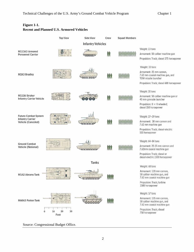
The purpose of the GCV is to transport a full squad while protecting it from hostile fire and supporting it with firepower. GCVs and other, similar infantry vehicles are distinct from tanks, which carry large guns and are not normally intended for soldier transport (see Figure 1-1). GCVs are also distinct from light tactical vehicles and trucks, such as high mobility multipurpose wheeled vehicles (HMMWVs), which are designed for transport but not protection. Today, the Army relies on the Bradley Infantry Fighting Vehicle to perform the squad transport function, and it intends to replace some of the current Bradleys with GCVs in heavy combat units.
Along with increased protection, the ability of the GCV to transport and deploy whole cohesive squads sets it apart from the Bradley. The current infantry platoon consists of three nine-soldier squads. Because the Bradley cannot carry a complete squad, the squad members and support soldiers, such as medics, ride among four vehicles.
The Army requires the GCV to be useful in all types of combat, from peacekeeping to irregular and conventional combat. Different types of combat put different demands on armored vehicles. The designs of previous generations of U.S. armored vehicles focused on conventional combat. While the Bradley is a proven weapon in conventional combat, it lacks protection against the types of weapons used in irregular warfare today, such as improvised explosive devices (IEDs), rocket-propelled grenades (RPGs), and other shaped-charge weapons fired at the side and rear of the vehicle.
Designing a single vehicle to carry a full squad and operate in all types of combat creates challenges. For example, the weapons the GCV will encounter and the angles from which it can be attacked are more
Technical Challenges of the U.S. Army’s Ground Combat Vehicle Program Chapter 1
2
Figure 1-1. Recent and Planned U.S. Armored Vehicles
Source: Congressional Budget Office.
Technical Challenges of the U.S. Army’s Ground Combat Vehicle Program Chapter 1
3
diverse than in conventional combat of previous years. Providing all-around protection against the potential threats—whether in the form of armor or high-technology solutions—increases the vehicle’s weight. A large vehicle is not only difficult to transport to the theater and consumes more fuel, it also damages roads and bridges and has trouble traversing narrow urban streets, creating problems in peacekeeping and counterinsurgency. The need to carry a full squad is also a crucial factor in determining the size and weight of the vehicle. Experience in Iraq and Afghanistan, however, has convinced the Army that the GCV must be effective in all scenarios.
Capacity for a Nine-Man Squad The number of people to be carried is an important parameter in armored vehicle design because it sets a minimum enclosed volume that must be protected. That volume then determines the weight required for armor, the power needed, the amount of fuel needed, and numerous other vehicle parameters.
The size of the U.S. Army mechanized squad has varied over the years from 12 in World War II, 11 in the Vietnam era, and 10 during the early portion of the Cold War.1 Since 1986 the U.S. Army has believed 9 to be the optimal number. 2 With an emphasis on the infantry squad in future combat, the Army views the inability of the Bradley to carry a full 9-man squad as a significant liability.
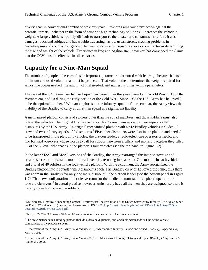
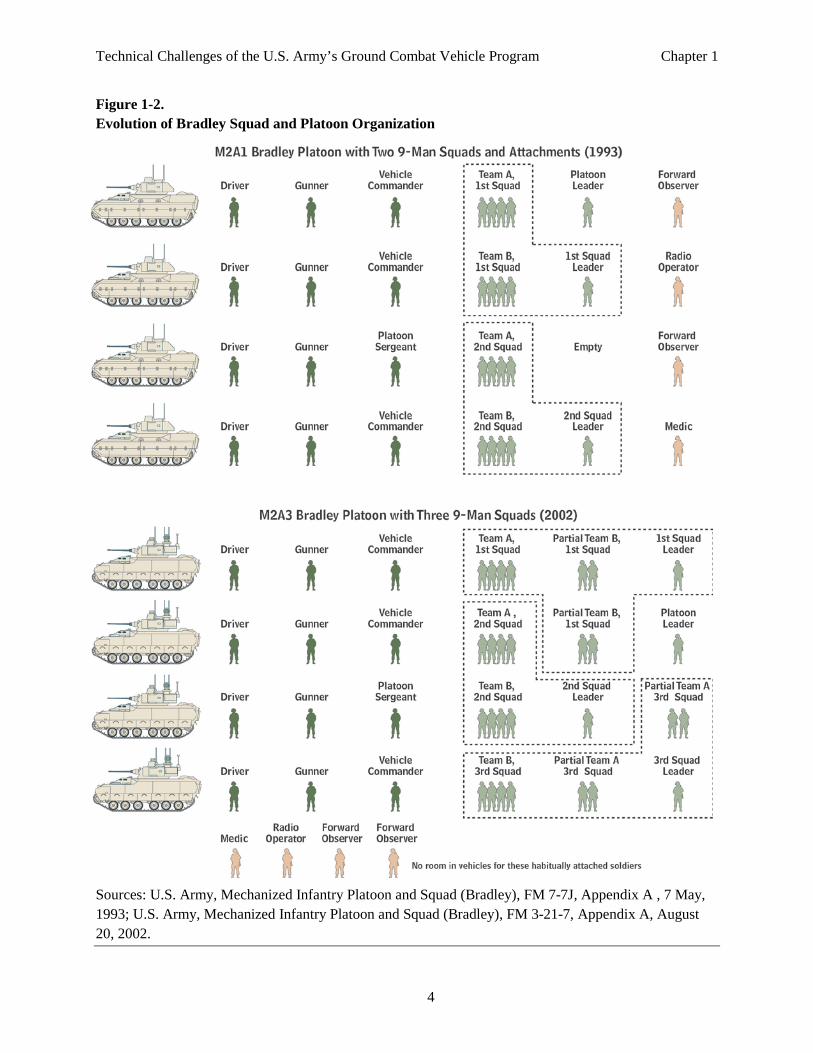
A mechanized platoon consists of soldiers other than the squad members, and those soldiers must also ride in the vehicles. The original Bradley had room for 3 crew members and 6 passengers, called dismounts by the U.S. Army. An original mechanized platoon with 4 M2 Bradley vehicles included 12 crew and two infantry squads of 9 dismounts.3 Five other dismounts were also in the platoon and needed to be transported in the platoon’s vehicles: the platoon leader, a radio-telephone operator, a medic, and two forward observers whose role is to call for support fire from artillery and aircraft. Together they filled 35 of the 36 available spaces in the platoon’s four vehicles (see the top panel in Figure 1-2).4
In the later M2A2 and M2A3 versions of the Bradley, the Army rearranged the interior stowage and created space for an extra dismount in each vehicle, resulting in spaces for 7 dismounts in each vehicle and a total of 40 soldiers in the four-vehicle platoon. With the extra men, the Army reorganized the Bradley platoon into 3 squads with 9 dismounts each. The Bradley crew of 12 stayed the same, thus there was room in the Bradleys for only one more dismount—the platoon leader (see the bottom panel in Figure 1-2). That new configuration did not leave room for the medic, platoon radio-telephone operator, or forward observers.5 In actual practice, however, units rarely have all the men they are assigned, so there is usually room for those extra soldiers.
1 See Karcher, Timothy, “Enhancing Combat Effectiveness: The Evolution of the United States Army Infantry Rifle Squad Since the End of World War II” (thesis), Fort Leavenworth, KS, 1989, http://stinet.dtic.mil/cgi-bin/GetTRDoc?AD=ADA407058& Location=U2&doc=GetTRDoc.pdf. 2 Ibid., p. 65. The U.S. Army Division 86 study reduced the squad size to 9 to save personnel. 3 The crew members in a Bradley platoon include 4 drivers, 4 gunners, and 4 vehicle commanders. One of the vehicle commanders is the platoon sergeant. 4 Department of the Army, U.S. Army Field Manual 7-7J, “Mechanized Infantry Platoon and Squad (Bradley),” Appendix A, May 7, 1993. 5 Department of the Army, U.S. Army Field Manual 3-21-7, “Mechanized Infantry Platoon and Squad (Bradley),” Appendix A, August 20, 2003.
Technical Challenges of the U.S. Army’s Ground Combat Vehicle Program Chapter 1
4
Figure 1-2. Evolution of Bradley Squad and Platoon Organization
Sources: U.S. Army, Mechanized Infantry Platoon and Squad (Bradley), FM 7-7J, Appendix A , 7 May, 1993; U.S. Army, Mechanized Infantry Platoon and Squad (Bradley), FM 3-21-7, Appendix A, August 20, 2002.
Technical Challenges of the U.S. Army’s Ground Combat Vehicle Program Chapter 1
5
Even with the extra space in the revised Bradleys, the squads were split among more than one Bradley. A split squad can be difficult to organize and control immediately after dismounting, especially when under fire and in complex terrain. The Army seeks to avoid that difficulty by requiring the GCV to carry the full 9-man squad. A four-vehicle GCV platoon will have room for 12 crew members and 36 dismounts. With three squads fully occupying three GCVs, the fourth GCV will have room for the platoon leader, forward observers, radio-telephone operator, and medic.
The Threat to Current and Future Forces The Army believes that the Bradley does not have enough space, weight, and power (SWAP) for additional armor or electronic systems necessary on the modern battlefield.6 The threat that modern weapons and forces present to the current armored vehicle fleet is the driving impetus of the GCV program.
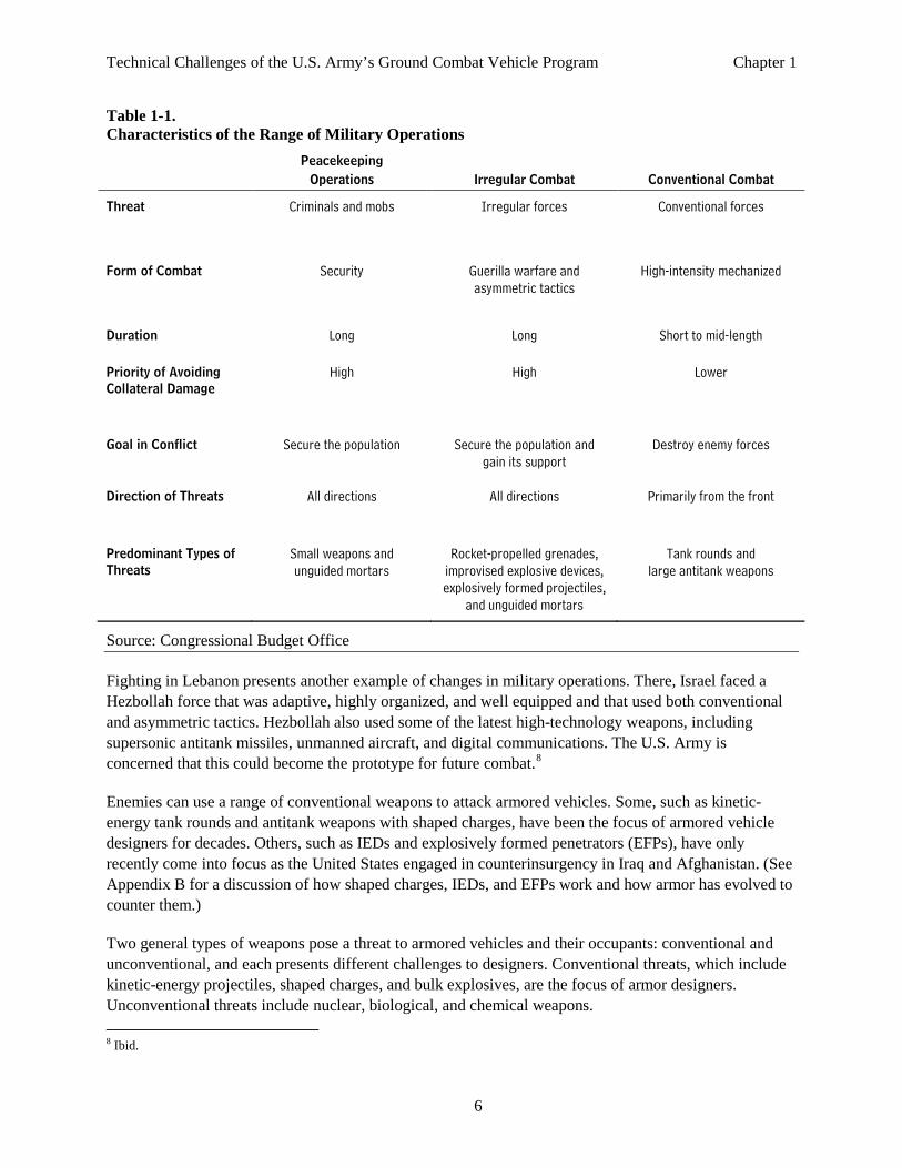
The Army states that future military operations will range from peacekeeping to irregular warfare to major combat operations involving conventional combat against an adversary equipped with armored forces. The different types of combat put different demands on combat vehicles, particularly the types of weapons that may be fired at the vehicle and the direction from which they strike the vehicle (see Table 1-1).
The emphasis of peacekeeping is on securing the local population while incurring minimal collateral damage, including damage to road infrastructure from the movement of heavy vehicles, in particular, vehicles with tracks. Because threat weaponry is minimal in peacekeeping missions, trucks and light vehicles are often sufficient, but the occasional combat vehicle may be useful.
Irregular warfare presents a greater challenge because guerilla fighters use asymmetric tactics such as IEDs and blending in with the civilian population to minimize the superiority of their adversary’s weapons. In those situations, the U.S. Army’s mission is often to gain the support of the population, so minimizing collateral damage is important. However, guerilla fighters can attack from any direction with a wide range of powerful weapons, making heavy weapons and armor a necessity for U.S. forces.
Major combat operations (in which conventional forces fight each other) are the most intense type of combat that the Army might conduct short of nuclear war. Because it is so intense, it usually lasts for a short duration as soldiers and weapons are consumed. This is the type of operation that the U.S. Army designed its heavy combat units to fight.
Combat operations in Iraq revealed a threat that included both conventional and irregular forces. The initial invasion and the 2004 battles for Fallujah and Najaf had U.S. forces engaged in intense combat, much of it in urban areas. Over time the threat shifted to a combination of terrorists, insurgents, militias, and criminal organizations in an insurgency, a transnational terrorist problem, and various proxy forces supported by hostile regimes.7
6 Department of the Army, Headquarters, Training and Doctrine Command, The Army Capstone Concept Operational Adaptability—Operating Under Conditions of Uncertainty and Complexity in an Era of Persistent Conflict, TRADOC Pam 525-3-0, Fort Monroe, VA, December 21, 2009. 7 Ibid.
Technical Challenges of the U.S. Army’s Ground Combat Vehicle Program Chapter 1
6
Table 1-1. Characteristics of the Range of Military Operations
Peacekeeping
Operations Irregular Combat Conventional Combat
Threat Criminals and mobs Irregular forces Conventional forces
Form of Combat Security Guerilla warfare and asymmetric tactics
High-intensity mechanized
Duration Long Long Short to mid-length
Priority of Avoiding Collateral Damage
High High Lower
Goal in Conflict Secure the population Secure the population and gain its support
Destroy enemy forces
Direction of Threats All directions All directions Primarily from the front
Predominant Types of Threats
Small weapons and unguided mortars
Rocket-propelled grenades, improvised explosive devices, explosively formed projectiles,
and unguided mortars
Tank rounds and large antitank weapons
Source: Congressional Budget Office
Fighting in Lebanon presents another example of changes in military operations. There, Israel faced a Hezbollah force that was adaptive, highly organized, and well equipped and that used both conventional and asymmetric tactics. Hezbollah also used some of the latest high-technology weapons, including supersonic antitank missiles, unmanned aircraft, and digital communications. The U.S. Army is concerned that this could become the prototype for future combat.8
Enemies can use a range of conventional weapons to attack armored vehicles. Some, such as kinetic-energy tank rounds and antitank weapons with shaped charges, have been the focus of armored vehicle designers for decades. Others, such as IEDs and explosively formed penetrators (EFPs), have only recently come into focus as the United States engaged in counterinsurgency in Iraq and Afghanistan. (See Appendix B for a discussion of how shaped charges, IEDs, and EFPs work and how armor has evolved to counter them.)
Two general types of weapons pose a threat to armored vehicles and their occupants: conventional and unconventional, and each presents different challenges to designers. Conventional threats, which include kinetic-energy projectiles, shaped charges, and bulk explosives, are the focus of armor designers. Unconventional threats include nuclear, biological, and chemical weapons. 8 Ibid.
Technical Challenges of the U.S. Army’s Ground Combat Vehicle Program Chapter 1
7
Within those categories, the threats vary in severity. The GCV is more likely to see less severe threats such as small arms fire and hand-held antitank rockets more often, although there may be some exceptions (see Figure 1-3). 9 Some of the key threats are discussed below and illustrate the technical challenges in designing a vehicle such as the GCV that is supposed to counter all of them.
Conventional Threats Kinetic-energy tank rounds. Perhaps the most challenging conventional threat that the GCV will face is cannon-launched, direct-fire projectiles that rely on kinetic energy to penetrate the vehicle armor and cause damage. Their high speed (up to 1.5 kilometers per second) and energy make them particularly difficult to counter or stop. Those rounds are usually fired by tanks. Traditionally, the best means to counter this threat is to shoot first and kill the opposing tank before it can shoot. Because those direct-fire projectiles usually require a tank to fire them, they probably will not be used in small-scale conflicts where the enemy does not have armored forces.
Large-caliber antitank guided missiles. Large-caliber antitank guided missiles are very capable weapons against heavy armored vehicles; they are only slightly less damaging than kinetic-energy weapons. They usually rely on shaped-charge warheads to penetrate and damage armored vehicles. Since they are guided and slower (about 200–400 meters/second) than kinetic-energy rounds, they allow a few more defensive options before impact. Furthermore, armor technology has advanced recently to the point where at present it has rough parity with shaped-charge threats. However, improvements in antitank guided missiles will continue and create a situation in which the capabilities of armor and threat leapfrog each other over time, thus it is difficult to predict whether armor or shaped-charge weapons will have the upper hand at any given time. 10
Large-caliber antitank guided missiles tend to be complex and expensive. They are less likely to be encountered in small-scale conflict, although Hezbollah’s use of Kornet missiles in Lebanon is an example of an irregular force using such weapons.
Small antitank guided missiles. The more likely shaped-charge threat for GCVs is the hand-held antitank rocket and, to a lesser extent, the small antitank guided missile. Hand-held antitank rockets, which include the ubiquitous Rocket-Propelled Grenade-7 (RPG-7), are challenging threats and widely available to nearly all potential opponents. Later versions of the RPG-7 are even more capable and have the ability to penetrate very substantial armor. Even the earlier versions can be deadly when used in swarms or volley fire as the Chechens did in Grozny against the Russians and Hezbollah did against the Israelis.
Precision artillery. Shaped-charge warheads fired by precision artillery are another challenging threat to the GCV. They can attack a vehicle from the top, where the vehicle has less armor and is usually more vulnerable. However, a fairly substantial military infrastructure is required to employ such weapons, including large-caliber cannon, trained spotters, communications networks, and extensive supply lines. The rounds are also expensive. Precision artillery rounds are weapons that will most likely be used only by well-organized forces in major combat operations. In contrast, mortars require much less infrastructure
9 Handheld antitank rockets are also known as rocket-propelled grenades, or RPGs. 10 The U.S. TOW heavy antitank missile has a velocity of 200 meters per second, while the Russian AT-4 Sagger is slightly slower. The U.S. Hellfire and Russian AT-6 are supersonic at velocities of about 420 meters per second. (Jane’s Infantry Weapons, 1990–91 and Jane’s Air Launched Weapons, issue 47.)
Technical Challenges of the U.S. Army’s Ground Combat Vehicle Program Chapter 1
8
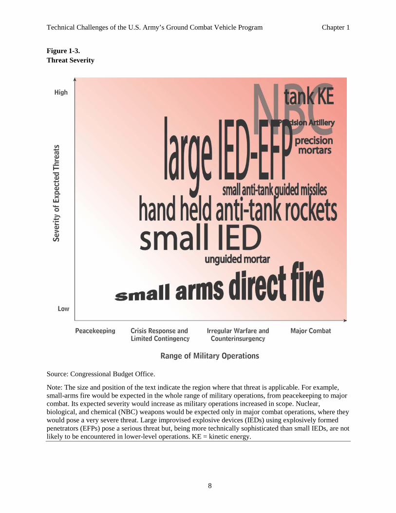
Figure 1-3. Threat Severity
Source: Congressional Budget Office.
Note: The size and position of the text indicate the region where that threat is applicable. For example, small-arms fire would be expected in the whole range of military operations, from peacekeeping to major combat. Its expected severity would increase as military operations increased in scope. Nuclear, biological, and chemical (NBC) weapons would be expected only in major combat operations, where they would pose a very severe threat. Large improvised explosive devices (IEDs) using explosively formed penetrators (EFPs) pose a serious threat but, being more technically sophisticated than small IEDs, are not likely to be encountered in lower-level operations. KE = kinetic energy.
Technical Challenges of the U.S. Army’s Ground Combat Vehicle Program Chapter 1
9
and are a more likely threat. Mortars equipped with precision-guided munitions can pose a serious threat if the opposing force is able to acquire them.
Unguided artillery. Unguided artillery and mortars pose less of a threat to armored vehicles because it is difficult to get hits on armored vehicles with such inaccurate weapons. Recent conflicts suggest that insurgents prefer to use stationary IEDs to target vehicles.11
Improvised explosive device. An IED, also known as a roadside bomb, is a homemade bomb constructed and deployed in ways other than in conventional military action. It may be constructed of conventional military explosives, such as an artillery round attached to a detonating mechanism, or of home-made components. IEDs range in size and severity from one pound to hundreds of pounds of explosive, with or without fragments and/or shaped-charged projectiles.
IEDs have become the predominant weapon used by insurgents and terrorists. In the second Iraq War and in the fighting in Afghanistan, the insurgents have used IEDs extensively against coalition forces and are responsible for the largest number of coalition casualties.12
Small arms fire. Small arms fire (bullets from machine guns and assault rifles) presents the least significant threat to armored vehicles because even light armor can usually prevent damage. Generally, if a vehicle is protected against larger threats, small arms fire is not an issue. The main danger from small arms fire is to crew members who remain exposed during operation. Recent U.S. and Israeli vehicles include features to protect the crew from small arms fire while still allowing them to see what is going on around them and to conduct their mission. Those features include transparent armor windows and remote sensors and weapons.
Unconventional Threats. Protection against chemical, biological, radiological, and nuclear threats poses special challenges. Because of the unique nature of those weapons, an attack may be well under way before the target is aware of the threat, and thus the victim of such an attack may not respond adequately before being incapacitated. Chemical, biological, and radiological weapons can produce a wide range of toxic effects that often require tailored medical countermeasures, particularly for biological agents. In addition, detecting those threats requires additional systems, which increases the complexity of systems on the vehicle and the amount of information that must be analyzed to find and confirm the existence a threat.
Balanced against the challenges of detecting, avoiding, and recovering from exposure to these weapons are challenges for the adversary who deploys them. Chemical, biological, and nuclear weapons often require a relatively high level of technical sophistication in order to produce those agents and deploy them effectively. The weapons often require components that are not readily available or are tightly controlled. In addition, they make poor military weapons because they can contaminate large areas of the battlefield and be difficult to control. Also, many are considered weapons of mass destruction whose use is banned by international treaty. The possibility of dire consequences for the adversary who deploys these weapons may not justify the immediate military advantages gained by using them. As a result, the probability of
11 Insurgents in Iraq and Afghanistan used unguided mortar fire to harass U.S. fixed installations. 12 Joint Improvised Explosive Device Defeat Organization (JIEDDO), Weapon Technical Intelligence Handbook, Version 1.0 (Unclassified), August 2009, p. 1.

Technical Challenges of the U.S. Army’s Ground Combat Vehicle Program Chapter 1
10
confronting a chemical, biological, radiological or nuclear weapon on the battlefield is much lower than for more traditional munitions, but the threat is not zero.
Designing and fielding an effective fighting vehicle that takes these threats into consideration requires a balance between protection and complexity.
Chapter 2. The Army’s Ground Combat Vehicle Program
The U.S. Army views all of its current armored infantry vehicles as inadequate for future conflict. They explicitly cite the age of the M113s and Bradley Infantry Fighting Vehicles as a problem.1 Many of those vehicles are more than 30 years old and have already been through several upgrades. (See Appendix A for a discussion of how current Army combat vehicles developed to this point.)
The Army intends to replace about 40 percent of the Bradleys in its heavy combat brigades with Ground Combat Vehicles (GCVs). The GCV will carry a full squad of infantry soldiers and provide very high levels of protection from all angles against a wide range of weapons. The Army plans to buy a total of 1,874 vehicles. (For a description of the effect of the Army’s plans on its heavy combat brigades, see Congressional Budget Office, The Army’s Ground Combat Vehicle Program and Alternatives, forthcoming.)
GCV Program Summary The GCV program began in June 2009 with the meeting of a blue-ribbon panel to determine requirements incorporating lessons learned from the canceled Future Combat Systems (FCS) program.2 Partially on the basis of the panel’s recommendations, the Army issued an initial request for proposals (RFP) for the GCV in February 2010.
By the time the bids from four contractors came in, there was a growing consensus throughout the Department of Defense (DoD) that the GCV requirements as outlined in the RFP were too ambitious and created a real possibility that high technical risks and immature technologies would lead to spiraling costs and schedule delays. As a result, the Army canceled the original GCV solicitation in August 2010 and announced that a restructured RFP for the GCV would be issued within 60 days.
The Army issued a revised RFP in November 2010 that left some flexibility in how the contractor could address the requirements.3 The RFP designated a manufacturing cost of between $9 million and $10.5 million per vehicle, an average procurement unit cost of $13 million per vehicle, and a sustainment cost of $200 per mile of operation. The Army announced an initial acquisition goal of 1,874 vehicles with production of the vehicle starting in 2018. The RFP stated that up to three contracts could be awarded for the technology development phase and as many as two for the subsequent engineering and manufacturing development phase.
1 The M113 Armored Personnel Carrier has been the armored transport for U.S. soldiers since the Vietnam War. Although it was replaced in the 1980s by the Bradley fighting vehicle as the infantry’s armored personnel carrier, numerous M113 vehicles still serve in the U.S. Army as ambulances and transport for support soldiers. 2 For further detail on the Ground Combat Vehicle program, see Andrew Feickert, The Army’s Ground Combat Vehicle (GCV) and Early Infantry Brigade Combat Team (E-IBCT) Programs: Background and Issues for Congress, CRS Report for Congress 7-5700 (Congressional Research Service, July 8, 2011). 3 Department of the Army, “Army Issues RFP for Ground Combat Vehicle,” December 1, 2010, www.army.mil/article/48843.
Technical Challenges of the U.S. Army’s Ground Combat Vehicle Program Chapter 2
12
The Pentagon’s Defense Acquisition Board reviewed and approved the revised program on July 21, 2011. The Pentagon’s senior procurement executive at the time, Ashton Carter, signed the acquisition decision memorandum with the caveat that “continuing approval” of the program will be contingent on the Army’s meeting an affordability target of an average procurement unit cost of $13 million in fiscal year 2011 dollars. 4 The memo also directed the Army to conduct a new analysis of alternatives and a market study of comparable infantry fighting vehicles that already exist and potentially could meet the requirements of the GCV program. (See Box 2-1 for the approaches that other countries have taken to provide armored transportation for infantry.)
The Congress also expressed interest in the new analysis. Title II, Sec. 211, of the National Defense Authorization Act for Fiscal Year 2012 (Public Law 112-81) limited the Army’s ability to obligate or expend more than 70 percent of authorized funds for the GCV program until the Army had submitted a report to lawmakers containing an analysis of alternatives that examines the revised design concept for the GCV.
In response to the revised RFP, three teams submitted proposals.5 In August 2011, the Army awarded contracts valued at about $450 million each to two of the contractor teams: one led by General Dynamics Land Systems and the other by BAE Systems.6 An SAIC-led team did not receive a contract award, and they protested that decision. The Government Accountability Office denied the protest in December 2011, and the contractors that won the award began work at that time.
Summary of the Army’s Requirements for the GCV The Army revised the requirements that the contractors must meet for the second GCV solicitation by adopting a tiered and incremental acquisition strategy. Tier 1 requirements are features that the GCV must provide in its initial version and that cannot be deferred. Tier 2 contains features for which the bidder must offer at least some capability in the vehicle’s first version, even if the full requirement cannot be met until later versions. Tier 3 has the lowest-priority features and may be deferred to a future version. The Army wants the GCV to meet as many of the Tier 2 and Tier 3 requirements as possible while still meeting the cost target.7
There are 135 requirements in Tier 1 that can be grouped into four main categories, which the Army calls the “Big Four.” The GCV must:
1. Protect the crew against a specified list of threats.
2. Carry the vehicle crew and an infantry squad of 9 soldiers and their equipment, including weapons, ammunition, supplies, food and water.
4 Average unit procurement cost is the total procurement cost divided by the number of units procured. It does not include costs for research and development, support equipment, training equipment, technical data, or spares. 5 Advanced Defense Vehicle Systems decided to withdraw from competition in response to the revised RFP. 6 The General Dynamics team includes Lockheed Martin, Raytheon Company and Tognum America, Inc. The BAE Systems team includes Northrop Grumman, QinetiQ, iRobot Corporation, MTU, and Saft. 7 For a list of all the GCV requirements by tier, see Department of the Army, Program Executive Office, Ground Combat Systems, GCV Performance Specification—Tiered, attachment 26, Warren, MI, November, 2010.
Technical Challenges of the U.S. Army’s Ground Combat Vehicle Program Chapter 2
13
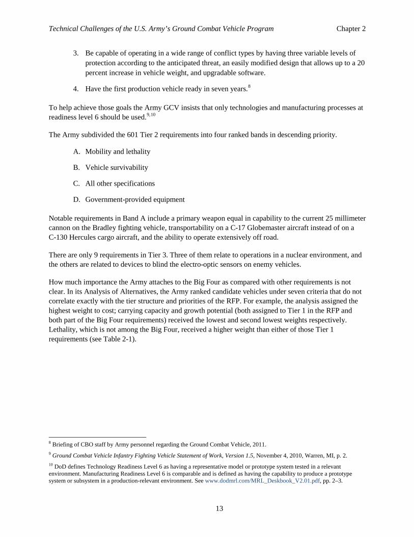
3. Be capable of operating in a wide range of conflict types by having three variable levels of protection according to the anticipated threat, an easily modified design that allows up to a 20 percent increase in vehicle weight, and upgradable software.
4. Have the first production vehicle ready in seven years.8
To help achieve those goals the Army GCV insists that only technologies and manufacturing processes at readiness level 6 should be used.9,10
The Army subdivided the 601 Tier 2 requirements into four ranked bands in descending priority.
A. Mobility and lethality
B. Vehicle survivability
C. All other specifications
D. Government-provided equipment
Notable requirements in Band A include a primary weapon equal in capability to the current 25 millimeter cannon on the Bradley fighting vehicle, transportability on a C-17 Globemaster aircraft instead of on a C-130 Hercules cargo aircraft, and the ability to operate extensively off road.
There are only 9 requirements in Tier 3. Three of them relate to operations in a nuclear environment, and the others are related to devices to blind the electro-optic sensors on enemy vehicles.
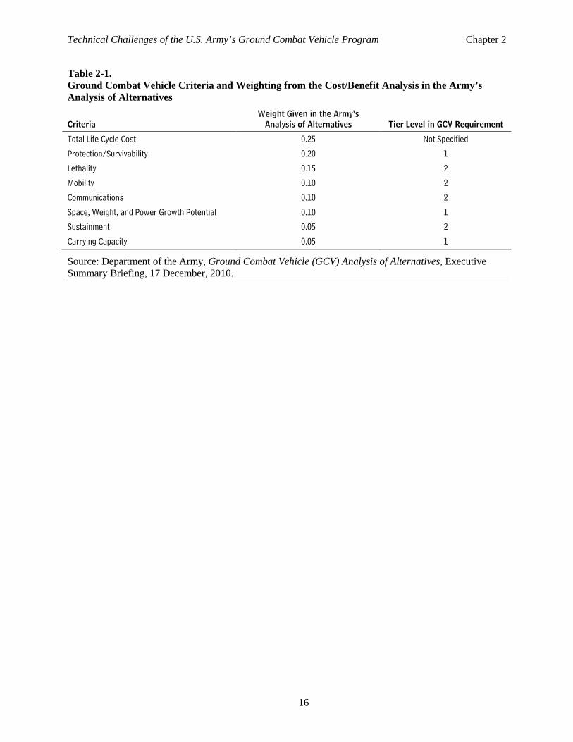
How much importance the Army attaches to the Big Four as compared with other requirements is not clear. In its Analysis of Alternatives, the Army ranked candidate vehicles under seven criteria that do not correlate exactly with the tier structure and priorities of the RFP. For example, the analysis assigned the highest weight to cost; carrying capacity and growth potential (both assigned to Tier 1 in the RFP and both part of the Big Four requirements) received the lowest and second lowest weights respectively. Lethality, which is not among the Big Four, received a higher weight than either of those Tier 1 requirements (see Table 2-1).
8 Briefing of CBO staff by Army personnel regarding the Ground Combat Vehicle, 2011. 9 Ground Combat Vehicle Infantry Fighting Vehicle Statement of Work, Version 1.5, November 4, 2010, Warren, MI, p. 2. 10 DoD defines Technology Readiness Level 6 as having a representative model or prototype system tested in a relevant environment. Manufacturing Readiness Level 6 is comparable and is defined as having the capability to produce a prototype system or subsystem in a production-relevant environment. See www.dodmrl.com/MRL_Deskbook_V2.01.pdf, pp. 2–3.
Technical Challenges of the U.S. Army’s Ground Combat Vehicle Program Chapter 2
14
Box 2-1. Foreign Countries’ Approach to Infantry Fighting Vehicles The United States is not the first country to develop heavy infantry fighting vehicles. The combat experience of other nations and how they responded with their vehicle development may help put the United States’ program for ground combat vehicles (GCV) into perspective.
In the past two decades, both Israel and Russia have engaged in heavy conventional combat in urban areas against insurgent and irregular forces. Both countries evolved heavy infantry fighting vehicles to engage in that kind of combat. Those vehicles may meet some, but probably not all, of the United States’ GCV requirements.
Israel developed several infantry fighting vehicles based on a tank chassis. Around 1988, it developed the Achzarit vehicle using chassis from Soviet-designed T-54 or T-55 tanks captured from Arab armies during the Arab-Israeli wars. The turret was removed and chassis and engine modified so that soldiers could exit from the rear. The Achzarits weigh about 44 tons and have engines that deliver between 650 and 850 horsepower (hp), depending on the variant. The tanks can carry 3 crew members and up to 7 infantry.1
Starting in 1994, the Israelis converted several of their 1945 vintage Centurion tanks to infantry fighting vehicle configurations with at least three main variants: Nagmashot, Nakpadon, and Nagmachon. The latest Nagmachon vehicles have increased belly armor for mine protection and a distinctive armored extension on the top, called the doghouse. Those features optimize it for counterinsurgency operations but reduce its capacity for traditional mechanized warfare. The Nagmachon weighs 52 tons, has a 750 hp engine, and carries a crew of 2 and 10 infantry.2
The Namer is the Israelis’ latest heavy armored vehicle built from converted tanks (see the top photograph on p. 15). In this case the base chassis was a Merkava tank. The Merkava was well suited to the infantry conversion because even the tank version has a rear door and room inside for 2 infantry. The Namer has a remote weapon station on top. It weighs 60 tons, has a 1,200 hp engine, and can carry 2 crew members and 10 infantry.3 The U.S. Army is reexamining the Namer as a possible alternative for the GCV program.
The Russians’ experience in Chechnya, where their light infantry fighting vehicles suffered extensive losses in urban combat, convinced them to develop heavy infantry fighting vehicles based on tanks. The BTR-T is one such vehicle developed using the hull of T-55 tanks. The BTR-T can carry several different machine guns or cannon in a small turret while carrying up to 5 passengers. The vehicle weighs 39 tons and has a 520 hp engine.4
The BMPT is a newer Russian armored vehicle based on the chassis of a T-72 tank. It is less an infantry carrier and more an armored support vehicle because it has only a total capacity of 5 including the crew. It weighs 47 tons and has a 1,000 hp engine.5
The German Army took a different approach in designing its Puma infantry fighting vehicle in that the Puma is not based on an existing tank chassis but is a new design that is lighter and smaller than the tank-based vehicles (see the bottom photograph on p. 15). It has two protection levels. Level A, at 31.5 tons, is transportable by the Airbus A400M aircraft, a tactical transport aircraft slightly larger than the United States’ C-130. Protection level B weighs 43.7 tons when combat loaded. The vehicle has a 1,072 horsepower engine and can carry a crew of 3 plus 6 infantry.6 The vehicle includes a turret with a 30 millimeter cannon and a 5.56 millimeter machine gun.
1 Jane’s Armor and Artillery, 2005–2006, and /www.military-today.com/apc/achzarit.htm. 2 See www.military-today.com/apc/nakpadon_heavy_apc.htm. 3 Jane’s Armor and Artillery, 2005–2006, and www.military-today.com/apc/namera.htm. 4 Jane’s Armor and Artillery, 2005–2006, p. 370. 5 Ibid., p. 367. 6 The Puma that the U.S. Army considered for the GCV has a capacity for three crew plus seven infantry.
Technical Challenges of the U.S. Army’s Ground Combat Vehicle Program Chapter 2
15
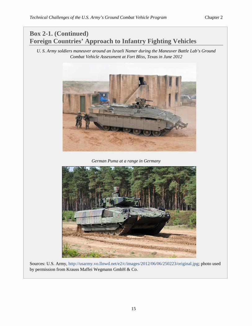
Box 2-1. (Continued) Foreign Countries’ Approach to Infantry Fighting Vehicles
U. S. Army soldiers maneuver around an Israeli Namer during the Maneuver Battle Lab’s Ground Combat Vehicle Assessment at Fort Bliss, Texas in June 2012
German Puma at a range in Germany
Sources: U.S. Army, http://usarmy.vo.llnwd.net/e2/c/images/2012/06/06/250223/original.jpg; photo used by permission from Krauss Maffei Wegmann GmbH & Co.
Technical Challenges of the U.S. Army’s Ground Combat Vehicle Program Chapter 2
16
Table 2-1. Ground Combat Vehicle Criteria and Weighting from the Cost/Benefit Analysis in the Army’s Analysis of Alternatives
Criteria Weight Given in the Army’s
Analysis of Alternatives Tier Level in GCV Requirement
Total Life Cycle Cost 0.25 Not Specified
Protection/Survivability 0.20 1
Lethality 0.15 2
Mobility 0.10 2
Communications 0.10 2
Space, Weight, and Power Growth Potential 0.10 1
Sustainment 0.05 2
Carrying Capacity 0.05 1
Source: Department of the Army, Ground Combat Vehicle (GCV) Analysis of Alternatives, Executive Summary Briefing, 17 December, 2010.
Chapter 3. Considerations for Ground Combat Vehicles
There are four basic functions that a ground combat vehicle must perform: it must protect, move, shoot, and communicate. There are technical, tactical, or operational approaches to each with associated benefits, risks, and costs. The Army has defined the capabilities that the Ground Combat Vehicle (GCV) should have in each area.
Protect Weight and protection generally go hand in hand. More protection requires more material, which requires more weight, but heavier vehicles are more difficult to transport to theaters, cannot easily operate in areas with narrow roads and small bridges, consume more fuel, and need more logistic support.
Protecting the crew is the Army’s the highest priority function for the GCV program. The Army assigns lower priority to protecting the vehicle and its systems even though most measures that protect the crew will also protect the vehicle to some extent.
In the past, armored vehicles relied on “bulk” armor for protection, usually in the form of steel plates of rolled homogeneous armor. As antitank weapons became more capable, vehicle designers added more steel to increase protection. By the 1970s, that cycle had reached a limit. It was no longer practical to add just steel to protect a vehicle from the highly capable antitank missiles and rocket-propelled grenades that proliferated on battlefields—the vehicles would have been too heavy and bulky to be useful in combat. 1
In recognition of that limit, some armored vehicles actually became lighter, attempting to use the better mobility afforded by less weight to avoid getting hit. The German Leopard 1 is a prominent example.2 In the 1980s, the balance swung back to protection as developers came up with improved armor formulations that could stop antitank weapons. The Abrams and Challenger tanks are two examples of combat vehicles that used those armor formulations.3
In response to the improved armor, developers introduced new antitank weapons, and vehicles again grew heavier as designers sought to maintain protection against those increasingly more capable antitank threats. For example, when the Abrams was modified with improved armor, its weight rose from 64 tons to 68 tons. Similarly, the Bradley Infantry Fighting Vehicle went from 25 tons to 33 tons. One compromise that vehicle designers made was to use heavy armor only on the parts of the vehicle that were expected to be hit more often. In conventional combat with tank-on-tank battles, that usually meant the
1 As U.S. Army Major General Webster stated, “Throughout history, there’s a pendulum that swings between adding more armor protection and adding more maneuverability to combat vehicles.” (“Army Approval for Heavier Armor in Iraq Delayed Until Last Month,” Inside the Pentagon, January 20, 2005.) 2 Dougherty, Martin J., Compared and Contrasted: Tanks from World War I to Today, Amber Books, London, UK, 2010, p. 186. 3 Kelly, Orr, King of the Killing Zone, W.W. Norton & Co, February 1989. This book has a good description of the history of Chobham armor and its role in development of the M1 Abrams tank.
Technical Challenges of the U.S. Army’s Ground Combat Vehicle Program Chapter 3
18
frontal arc of the vehicle that received the greatest proportion of incoming fire in conventional combat (see Figure 3-1).4 Tanks and infantry vehicles in the 1990s could have up to two feet of armor on front surfaces with perhaps one-tenth of that on the sides.5
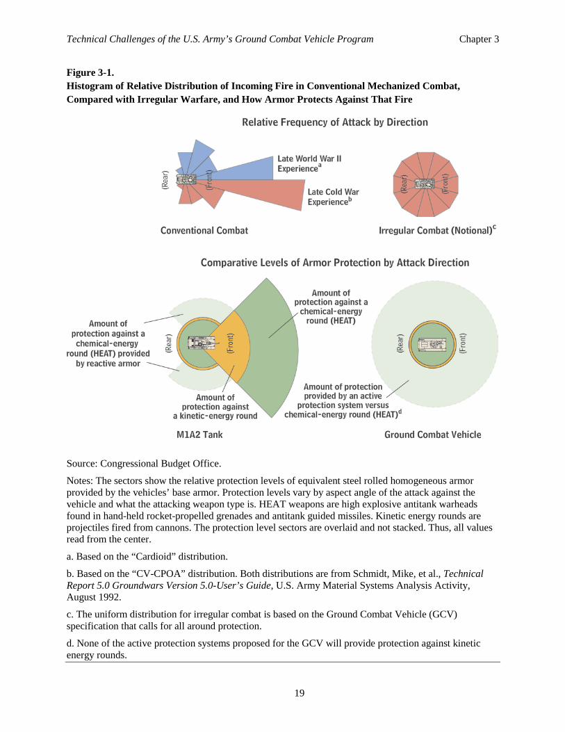
With anti-armor weapons still increasing in lethality, the armor side of the balance is again at a practical limit, as main battle tanks and infantry fighting vehicles have reached weights approaching 70 tons. Furthermore, vehicles are beginning to be threatened by weapons from all aspects, not just the front (see Figure 3-1). Some advanced countries have designed weapons that can use high-technology infrared or radar sensors and guidance to attack the tops or engine compartments of vehicles. Less complex approaches have also evolved, such as mines designed to attack the weaker bottoms of vehicles or improvised explosive devices (IEDs) to attack the weaker sides of vehicles, approaches that are particularly effective in insurgencies where vehicles operate over the same roads for months or years (see Figure 3-2). Those have been the favored modes of attack in Afghanistan and Iraq, and countering them is a primary focus of the GCV program.
Given the growing capabilities and attack angles of modern threats, designers now look at preventing the vehicle from being engaged at all to help it survive. Or, if the vehicle is engaged, they try to prevent the threat from hitting the vehicle. That approach results in a multilayered scheme—the “survivability onion”—in which armor is one of the last lines of defense (see Figure 3-3):
• Destroy enemies beyond their engagement range;
• Avoid being detected;
• If detected, avoid being engaged;
• If engaged, avoid being hit;
• If hit, prevent penetration; and
• If penetrated, minimize damage.
All layers of the survivability onion can be viewed as partial solutions; each layer contributes a portion of the overall survivability. Different vehicles or systems can take different approaches to survivability by emphasizing certain layers over others. The GCV program focuses on the last three (or innermost) layers of the onion, but the first three are discussed briefly here as well.
Destroy Enemies Beyond Their Engagement Range The first layer of defense is to use long-range sensors on the ground vehicle or at another location to detect threats before those threats can bring their weapons to bear on the vehicle. Then, by using long-range weapons on board the vehicle or by calling for support from remote weapons, the vehicle’s crew can engage and destroy the threat. For example, the GCV could use an off-board sensor to detect an
4 Studies of mechanized combat showed that the hits on armored vehicles were distributed unevenly, with more toward the front and fewer toward the rear. Designers approximated that distribution with a cardioid statistical formula and designed vehicle armor accordingly. See, for example, Steeb, Randall, et al., An Exploration of Integrated Ground Weapons Concepts for Armor/Anti-Armor Missions, RAND Corporation, Santa Monica, 1991, and Department of the Army, Material Systems Analysis Activity, Groundwars Version 5.0—User’s Guide, Technical Report No. 530, August 1992, p. 37. 5 Green, Michael, and Stewart, Greg, Modern U.S. Tanks and AFVs, MBI Publishing, St Paul, MN, 2003, p. 10.
Technical Challenges of the U.S. Army’s Ground Combat Vehicle Program Chapter 3
19
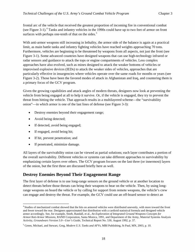
Figure 3-1. Histogram of Relative Distribution of Incoming Fire in Conventional Mechanized Combat, Compared with Irregular Warfare, and How Armor Protects Against That Fire
Source: Congressional Budget Office.
Notes: The sectors show the relative protection levels of equivalent steel rolled homogeneous armor provided by the vehicles’ base armor. Protection levels vary by aspect angle of the attack against the vehicle and what the attacking weapon type is. HEAT weapons are high explosive antitank warheads found in hand-held rocket-propelled grenades and antitank guided missiles. Kinetic energy rounds are projectiles fired from cannons. The protection level sectors are overlaid and not stacked. Thus, all values read from the center.
a. Based on the “Cardioid” distribution.
b. Based on the “CV-CPOA” distribution. Both distributions are from Schmidt, Mike, et al., Technical Report 5.0 Groundwars Version 5.0-User’s Guide, U.S. Army Material Systems Analysis Activity, August 1992.
c. The uniform distribution for irregular combat is based on the Ground Combat Vehicle (GCV) specification that calls for all around protection.
d. None of the active protection systems proposed for the GCV will provide protection against kinetic energy rounds.
Technical Challenges of the U.S. Army’s Ground Combat Vehicle Program Chapter 3
20
Figure 3-2. Comparison of Vertical Attack Angles in Conventional and Irregular Combat
Source: Congressional Budget Office.
enemy armored force and have other forces engage it with air power, attack helicopters, or indirect artillery fire before the threat can shoot at the GCV.
The Future Combat Systems (FCS) vehicles and, to a lesser extent, the Stryker vehicles were to be designed to rely very heavily on the outer layer of protection.6 The survivability of those relatively light vehicles was to come not from heavy armor but from an extensive system of networked sensors that would provide near-complete awareness of the situation around the vehicle while remote weapons killed most threats as described above. The advanced networks would analyze and disseminate the intelligence and targeting data. The approach was touted by some in the Army as trading armor for situational awareness.7
To date, however, the networks have not been able to provide the necessary information in a complete and timely manner. The existing Blue Force Tracking and Force XXI Battle Command Brigade and Below systems have worked to some extent but are not sufficient to allow complete reliance on them in lieu of armor. For example, at the 2003 Battle at Objective Peach during the U.S. invasion of Iraq, the U.S. brigade commander reported that his force was “surprised” and attacked by an Iraqi armored brigade that was not being detected by sensors, in spite of the deployed networks.8 In 2011, DoD’s Director of
6 Gonzales, Daniel, et al., Network-Centric Operations Case Study: The Stryker Brigade Combat Team, RAND Corporation, Arlington, VA, 2005, www.rand.org/pubs/monographs/2005/RAND_MG267-1.pdf. 7 For an example of that commonly expressed idea, see Van Fosson, Marion H., LTC, U.S. Army, “Future Combat Systems,” presentation at the 11th Annual U.S. Army Ground Vehicle Survivability Symposium, March 28, 2000. 8 Tisserand, John B., Network-Centric Warfare Case Study, Volume III: Network-Centric Warfare Insights, U.S. Army War College, Carlisle Barracks, PA, October 2006.
Technical Challenges of the U.S. Army’s Ground Combat Vehicle Program Chapter 3
21
Figure 3-3. Layers of Protection in the “Survivability Onion”
Source: Congressional Budget Office.
Operational Test and Evaluation concluded that recent testing by the Army showed that the sensor and communication networks were still not ready for that task.9
Furthermore, even proponents of network-based warfare agree that it may be impossible to establish sufficient situation awareness to avoid many engagements.10 For example, in Iraq and Afghanistan,
9 Statement of J. Michael Gilmore, Director, Operational Test and Evaluation, Office of the Secretary of Defense, before the Subcommittee on Tactical Air and Land Forces of the House Armed Services Committee, March 9, 2011. 10 Endsley, M., and Jones, W., Situation Awareness Information Dominance and Information Warfare, U.S. Air Force Armstrong Laboratory, Wright-Paterson Air Force Base, February 1997.
Technical Challenges of the U.S. Army’s Ground Combat Vehicle Program Chapter 3
22
insurgents who were dressed as civilians and armed with hand-held antitank weapons frequently avoided long-range detection and engaged coalition vehicles.11
Avoid Detection The next defensive layer is avoiding detection by the enemy. One way that can be achieved is by reducing the vehicle’s detectable characteristics, known as its signature. The GCV specifications call for some measures of signature reduction to help the vehicle avoid detection.
So-called stealth aircraft have been using signature reduction techniques for several years now. But controlling detectable signatures from a ground vehicle is a more difficult problem because ground vehicles have more signatures that must be controlled, including visual, radio, infrared, radar, noise, dust, exhaust, seismic vibration, and even smell signatures. Any one of them can cue a sensor that triggers additional searching or engagement. Dust trails, an issue that aircraft rarely have to consider, can be particularly difficult to manage. No U.S. ground combat system that has been deployed to date has an effective means of preventing dust signatures from forming, especially in dry environments.
Camouflage, an old technique that is still useful, is a form of signature reduction in the visible and perhaps infrared and radar frequencies of the electromagnetic spectrum. Camouflage techniques can use paint or nets to obstruct visual, infrared, and radar detection, but camouflage is not always practical. For example, when a vehicle is moving, its nets may not be usable, or dust may cover the camouflage paint.
Radar-absorbent materials and vehicle geometries that deflect radar are an important part of aircraft signature reduction but are less useful on tactical ground vehicles. Those materials tend to be expensive and difficult to maintain, especially on ground combat vehicles that routinely sustain damage to their exterior from environmental objects during use. The exterior of a ground combat vehicle is also likely to have armor, which may not be a good signature reducer, and efforts to reduce signatures will certainly make armor design more difficult. To date, there have not been many threat systems that use radar to detect, target, and engage ground vehicles.12 As a result, U.S. ground combat systems have not deployed radar-absorbent materials in their designs.
Blinding the sensors of enemy weapons or their operators can also prevent detection. The United States has done some work in this area, but there is concern about whether such countermeasures would be permissible under United Nations conventions.13 The Geneva Conventions prohibit blinding people with weapons, and it may be difficult to blind sensors without inadvertently blinding people. The United States deployed but did not use the Stingray antisensor system in the first Gulf War.14 Since then, the United States has not acknowledged fielding a blinding weapon aimed at optics or human vision.15
11 There are numerous reports of insurgents in civilian clothes attacking armored vehicles with antitank weapons. For example, see Bazzi, Mohamad, “Borrowing Hezbollah’s Tactics,” Long Island Newsday, August 12, 2005. 12 The U.S. Longbow system is probably the most notable antitank system that operates in the radar wavelengths. Other nations have developed radar-guided antitank missiles, such as the Russian AT-15 Springer, but they are not yet widely fielded. 13 The protocol on blinding laser weapons, Protocol IV of the 1980 Convention on Certain Conventional Weapons, was issued by the United Nations on October 13, 1995. It came into force on July 30, 1998. 14 Human Rights Watch, U.S. Blinding Laser Weapons, vol. 7, no. 5, May 1, 1995, www.unhcr.org/refworld/docid/3ae6a7cf10.html. 15 The United States has fielded some weapons that are intended to temporarily blind or dazzle an operator, but they are not in widespread use.
Technical Challenges of the U.S. Army’s Ground Combat Vehicle Program Chapter 3
23
A lower-technology approach is to use maneuvering and terrain (that is, tactics) to avoid detection. Those techniques may not always be possible but can be remarkably effective when they are used.16 A vehicle with more mobility has more freedom to maneuver, as described in the mobility section below.
If Detected, Avoid Engagement Once an enemy detects a ground vehicle, there are not many effective options to avoid engagement, especially for an infantry fighting vehicle as compared with a tank. In tank-on-tank battles, the classic response is to shoot first and kill the threat before it can shoot. But the GCV is not a tank and is not likely to have a weapon on board that can destroy an enemy tank quickly before being engaged.
The GCV could use maneuver and terrain to avoid engagement even if detected. Adopting defilade positions and performing berm drills are two maneuver tactics that vehicles can use to avoid engagement.17 Those tactics can be combined with self-screening smoke fired from onboard smoke dispensers to reduce the likelihood of being engaged.
If Engaged, Avoid Being Hit Once the enemy fires at the ground combat vehicle, the next defensive layer is to avoid being hit. If the ground vehicle can detect the incoming fire, it can try several techniques to avoid being hit, including evasive maneuver, electronic spoofing (called soft kill), or active measures (called hard kill). The timeline for action can be quite short, from a fraction of a second for direct fire from nearby threats to many seconds for some long-range antitank missiles.
Evasive maneuver. Evasive maneuver can be useful to avoid slower-moving guided missiles such as the early generation Soviet Sagger missiles that are still in some army inventories.18 However, evasive maneuver would not be effective against high-speed weapons such as direct-fire kinetic-energy rounds from a tank, newer supersonic missiles, and some automatic tracking weapons that use fire-and-forget technology.19
Electronic spoofing (Soft kill). Soft-kill countermeasures include infrared jammers, laser spot imitators, and radar jammers. They may prevent missile guidance from remaining locked onto the GCV, protecting the vehicle by causing the missile to miss the target or preventing the weapon warhead from fusing.20 However, countermeasures have proven difficult to implement in practice because they must be tailored
16 For example, the testing and analysis of the Army’s Forward Area Air Defense Program showed tactics used in large force-on-force battles dominated performance regardless of the proposed systems considered. See Congressional Budget Office, Army Air Defense for Forward Areas: Strategies and Costs, June 1986. 17 A unit or position is “in defilade” if it uses natural or artificial obstacles to shield or conceal itself from enemy fire. Berm drills are a tactical technique in which vehicles move quickly up a slope, come out of cover to shoot, and then back down the slope to break visual contact with enemy vehicles. 18 Department of the Army, Doctrine and Training Command, Soviet ATGM’s: Capabilities and Countermeasure, TRADOC Bulletin 2, Fort Monroe, VA, February 1975. 19 Fire-and-forget guidance missiles do not require further guidance after launch. Generally, the gunner programs information about the target into the missile just prior to launch. That information may include coordinates, radar measurements (including velocity), or an infrared image of the target. After it is fired, the missile guides itself by some combination of gyroscopes and accelerometers, global positioning system, internal radar, and infrared optics. 20 Lock-on signifies that a tracking or target-seeking system is continuously and automatically tracking a target in one or more coordinates (for example, range, bearing, elevation). Department of Defense, Dictionary of Military and Associated Terms, 2005.
Technical Challenges of the U.S. Army’s Ground Combat Vehicle Program Chapter 3
24
to a particular threat; they are not an umbrella defense that would work on a wide range of threats. For example, a millimeter wave radar jammer will not work against an infrared tracker.
Furthermore, when jammers offer umbrella coverage (broadband or barrage jamming), they can also have negative effects on friendly communications and electronic systems. That drawback limits their usefulness in some situations. For example, some barrage jammers used to counter IEDs in Iraq and Afghanistan disrupted normal radio communications for U.S. soldiers.21
Employing defensive electronic countermeasures in ground combat can have unexpected consequences: small changes in some parameters, such as radio frequencies, antenna shapes, or orientation, can cause large changes in effectiveness. In recent conflicts, the enemy has proven adaptive and agile in employing new techniques to stymie the Army’s countermeasures.22 As a result, defensive electronic countermeasures cannot be relied on for complete protection.
Active protection system (Hard kill). A hard-kill active protection system detects, engages, and destroys or neutralizes an incoming threat before it can hit a protected vehicle, actively firing some type of projectile to intercept the threat (see the top panel of Figure 3-4). Both of the contractors with candidates in the current GCV development are looking at active protection systems to meet the Army’s protection requirements.
A few examples of early active protection systems have been fielded, but their effectiveness is open to debate.23 Several nations, including the United States, have been developing active protection systems. The canceled FCS program planned to include active protection based on the Raytheon Quick Kill System.24 The Army does not currently have an active protection system in service.
In response to fiscal year 2008 legislation, DoD’s Director of Operational Test and Evaluation began the testing of several different active protection systems, including some foreign ones. The initial testing is now complete. According to his report, the results show limited effectiveness, and none of the systems are fully ready for fielding.25 Although it was an extensive test program with 147 planned live flight-test
21 Mihelich, Peggy, “Jamming Systems Play Secret Role in Iraq,” CNN, August 13, 2007, http://articles.cnn.com/2007-08-13/tech/cied.jamming.tech_1_jamming-detonation-signal?_s=PM:TECH. 22 See Department of the Army, “The Infantry Rifle Company,” Army Field Manual 3-21.10, Appendix G, “Improvised Explosive Devices, Suicide Bombers, Unexploded Ordnance, and Mines,” section I-G-10, “Countermeasures.” See also Clay Wilson, Improvised Explosive Devices in Iraq: Effects and Countermeasures, Report for Congress RS22330 (Congressional Research Service, November 23, 2005), p. CRS-3. 23 The first was the Soviet Drozd system created in 1977. The Soviets used a small number of Drozd systems with unknown effectiveness in Afghanistan and then abandoned the approach in the early 1980s. The Russian army later fielded a second system called Arena, but it has not been seen in public since the early 1990s.
In 2010, the Israeli army fielded the Trophy active protection system on some of its Merkava tanks, and it reportedly has successfully intercepted at least one threat missile. See Opall-Rome, B., “Trophy APS Scores 1st Operational Kill,” Defense News, March 14, 2011. 24 Government Accountability Office, Analysis of Processes Used to Evaluate Active Protection Systems, report to the Chairman, Subcommittee on Air and Land Forces, House Committee on Armed Services, June 2007, www.gao.gov/assets/270/261858.pdf. 25 Gilmore, J. Michael, Active Protection Systems Live Fire Test and Evaluation Report, Department of Defense, February 2012. Note that although the title is unclassified as are the findings reported here, the overall report is classified “Secret.”
Technical Challenges of the U.S. Army’s Ground Combat Vehicle Program Chapter 3
25
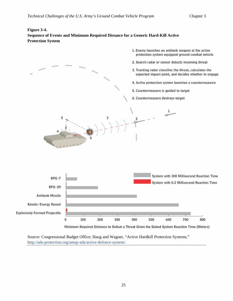
Figure 3-4. Sequence of Events and Minimum Required Distance for a Generic Hard-Kill Active Protection System
Source: Congressional Budget Office; Haug and Wagner, “Active Hardkill Protection Systems,” http://ads-protection.org/amap-ads/active-defence-system/.
Technical Challenges of the U.S. Army’s Ground Combat Vehicle Program Chapter 3
26
events, it involved simple scenarios under benign conditions.26 Whether those results can be extrapolated to more complex and realistic situations is not clear. Such testing was a necessary first step in understanding the operation of active protection systems but is not sufficient to fully characterize the performance of a system in actual practice with numerous technical and operational challenges.
An active protection system must meet several significant technical and operational challenges. It must:
• Work under extremely demanding circumstances and compressed timelines,
• Be robust against countermeasures,
• Pose no threat to friendly forces and civilians,
• Fit in the space and power allocated to it on the vehicle, and
• Be affordable.
The short time available to detect and react to threats to the GCV is probably the technical challenge that most analysts focus on when discussing active protection systems.27 A rocket-propelled grenade fired at short range will require the active protection system to detect and react in as little 1 second or less. Most systems will not be able to defeat rocket-propelled grenades fired at less than tens of meters because there will be insufficient time or distance to react. Active protection systems designed to defeat much higher velocity kinetic-energy rounds also must react very quickly. A tank-fired kinetic-energy round will take about 1 second to travel 1,500 meters. However, tank-fired kinetic-energy rounds are beyond the scope of the threats that the GCV program is considering.
Quick reaction times are essential for an active protection system to be effective. A system with a reaction time of 300 milliseconds would be able to intercept a typical antitank missile only if it was launched from at least 400 meters away; intercepting an RPG-7 would require that it be launched from at least 30 to 100 meters away (see the bottom panel of Figure 3-4). 28 By contrast, a system with a reaction time nearly 100 times faster (0.5 milliseconds) could intercept antitank missiles and RPG-7s launched from within 10 meters of the vehicle.
The available time may be shortened further if the control system has trouble detecting the incoming rounds. Battlefield clutter (man-made objects or natural features that create false signal echoes) can reduce the detection range of the system and create false targets.29 Enemy radar jammers may have the same effect. As a result, the active protection system may be delayed in detecting, or not ever detect, the
26 Seventy-six percent of the planned flight tests involved a single rocket-propelled grenade, whereas 19 percent had two simultaneous rocket-propelled grenades and 5 percent involved a single antitank guided missile. The test scenarios included no enemy countermeasures. Battlefield clutter was at a minimum. Over one-third of the planned flight tests were not executed because of technical and administrative reasons. From Koch, S., DoD Active Protection System (APS) Live Fire Test and Evaluation (LFT&E) Update for Senior Steering Board, August 31, 2011. 27 See, for example, Haug, D., and Wagner, H.J., “Active Hardkill Protection Systems—Analysis and Evaluation of Different System Concepts,” Strategie & Technik, Autumn 2009. 28 Depending on the speed of the RPG. 29 An infamous example of battlefield clutter causing a false target in tactical ground radar occurred when the radar on the Sergeant York divisional air defense gun system detected and classified a ventilation fan in a latrine on the test range as a potential threat. See Ditton, Major Michael H., “The DIVAD Procurement: A Weapon System Case Study,” DA Pam 27-50-188, The Army Lawyer, August 1988, p. 6.
Technical Challenges of the U.S. Army’s Ground Combat Vehicle Program Chapter 3
27
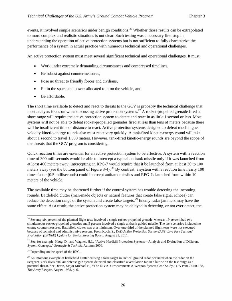
Figure 3-5. Possible Mutual Interference from Active Protection Systems Operating in Multiple Vehicle Formations
Source: Congressional Budget Office.
incoming round. The longer the system takes to pick an incoming round out of clutter or jamming, the less time it has to react.
Once the active protection system detects an incoming round, it must track the round for a period of time to determine if the trajectory poses a danger to the vehicle. Most systems do this by calculating whether the round will pass through a zone it deems a protected area. The system will attempt to intercept any incoming round that it predicts will enter this area. Demonstrations by contractors suggest that the systems may be capable of doing this in simple one-on-one situations, but how the systems will work in a situation where many active protection systems are operating side by side, with overlapping sectors of coverage and with multiple incoming threats, remains to be seen. (Figure 3-5 illustrates such a situation.) What will happen when multiple vehicles classify an incoming round as a threat? How do they coordinate a response? Those questions remain largely unanswered.
Coordinating the defensive fire among vehicles implies that the systems communicate with each other. Can the communications networks handle that traffic in the very short time required? Furthermore, there is the potential for mutual interference from having many radar systems transmitting in close proximity. Will the systems end up jamming each other? How to address mutual interference and how to allot defensive fire from multiple systems that might be in the protected area are technical issues whose solutions have not yet been determined.
Most of the active protection systems under development use explosive rounds as the intercepting device. The size of the intercepting projectiles varies from 105 mm high-explosive fragmenting warheads similar
Technical Challenges of the U.S. Army’s Ground Combat Vehicle Program Chapter 3
28
to artillery shells to smaller shaped charges.30 The risk of injury that the fragments and blast from those intercepting rounds would present to nearby soldiers, civilians, or other vehicles is a great concern. The fact that the intercepting rounds must be launched automatically without human intervention in order to meet the required timelines increases that concern. The United States and Israel have studied this problem and have tended to select interceptors for their systems that minimize—but do not eliminate—the hazard to people outside the vehicle.31
As discussed above, the basic physics and engineering of active protective defense is a challenge. That challenge is multiplied by the possibility that the enemy may adopt tactics or defense suppression measures to neutralize the effectiveness of the active protective system. Those measures can range from sophisticated jammers and decoys to simply firing a volley of cheap and widely available rocket-propelled grenades to overwhelm the defense.32
If Hit, Prevent Penetration When all the previous defense layers fail, it is the role of armor to prevent penetration and limit damage to the vehicle’s contents. Much of the GCV’s protection will be provided by armor.
There are two general classes of armor: passive and reactive. Passive systems work by stopping the projectile through the material properties of the armor components alone. Reactive systems work by inducing an explosion or other response in the armor to reduce the lethality of the projectile by disruption or deflection. Types of passive armor include bulk armor, modular armor, slat armor, and hull shaping. Types of reactive armor include explosive reactive armor and electromagnetic armor.
Ideally, the armor should be as effective and as lightweight as possible. Each type of armor is discussed below. (See Figure 3-6 for a graphical comparison of protection called for in the GCV program and in other combat vehicles against typical weapons.)
Bulk armor. The use of passive bulk armor—where the vehicle structure is also armor—was the primary method of building tanks and armored vehicles in the 20th century. Usually, that type of vehicle structure was made by casting a single hull or turret from a homogeneous material or by first riveting and then welding rolled sheets of metallic armor into a structure. For many years, armor designers measured protection levels by equivalent thicknesses of rolled homogeneous steel armor. The Army’s series of M60 tanks and the M113 armored personnel carrier utilized the homogeneous armor approach, albeit with different materials. The technique had the advantages of simple construction and relatively low cost. Designers made the armor thicker to achieve more protection. However, antitank weapons have improved
30 The range of explosives varies from the Army’s Close-in Active Protection System, which uses several 105 millimeter high explosive fragmenting interceptors arrayed around the vehicle, to DARPA’s Crosshairs system, which uses small downward-firing cutting charges to destroy the warhead. 31 The U.S. Army selected the Quick Kill system for the FCS in part because the system fires a shaped charge in a downward direction toward the ground, minimizing the chance that it could cause a friendly casualty. The Israeli Trophy system also uses shaped charges that it fires back on the azimuth of the original attack. That approach may minimize unintended casualties while also providing the opportunity to hit the missile shooter if the missile was fired a from short range—a so-called revenge kill. 32 Chechen fighters fired rocket-propelled grenades in volleys to overwhelm the reactive armor defenses of Russian tanks in the Grozny battle. See Edwards, Sean, Mars Unmasked: The Changing Face of Urban Operations, RAND Corporation, Santa Monica, CA, 2000, p. 29. Similar tactics could be used against active protection systems.
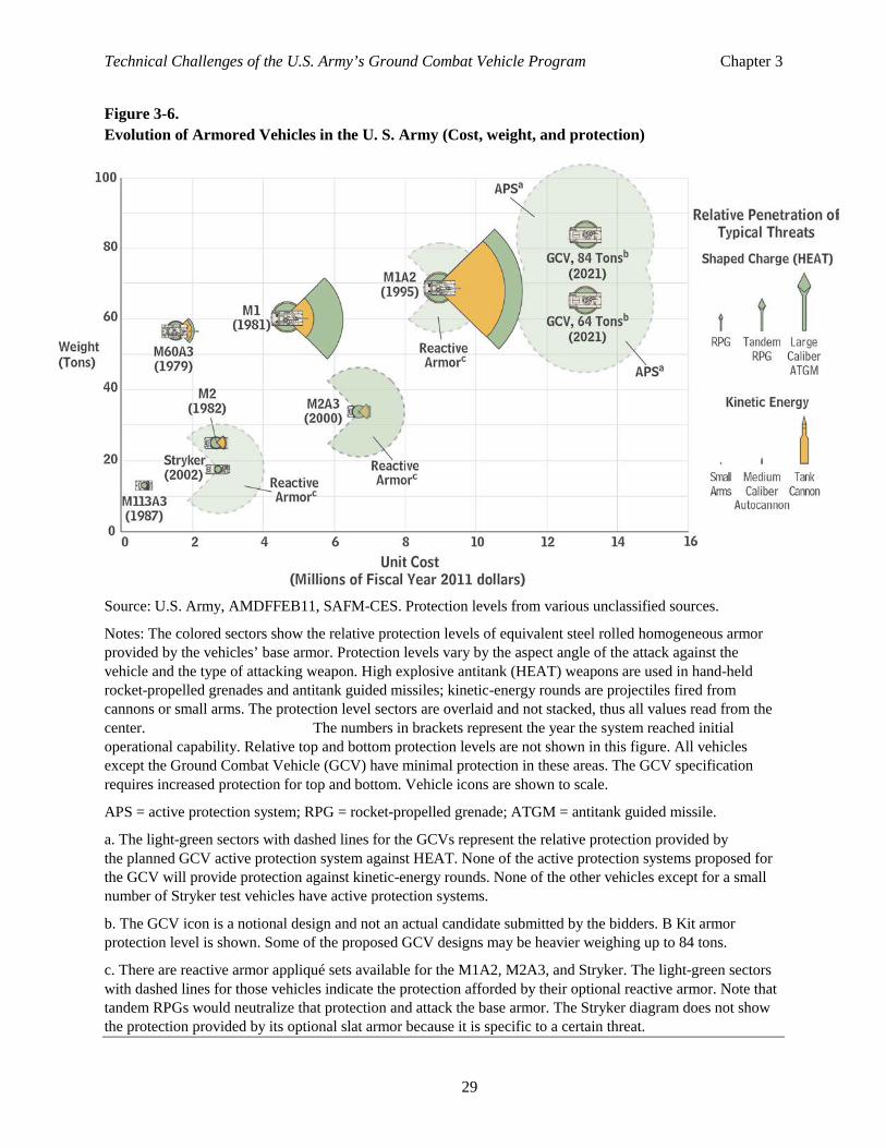
Technical Challenges of the U.S. Army’s Ground Combat Vehicle Program Chapter 3
29
Figure 3-6. Evolution of Armored Vehicles in the U. S. Army (Cost, weight, and protection)
Source: U.S. Army, AMDFFEB11, SAFM-CES. Protection levels from various unclassified sources.
Notes: The colored sectors show the relative protection levels of equivalent steel rolled homogeneous armor provided by the vehicles’ base armor. Protection levels vary by the aspect angle of the attack against the vehicle and the type of attacking weapon. High explosive antitank (HEAT) weapons are used in hand-held rocket-propelled grenades and antitank guided missiles; kinetic-energy rounds are projectiles fired from cannons or small arms. The protection level sectors are overlaid and not stacked, thus all values read from the center. The numbers in brackets represent the year the system reached initial operational capability. Relative top and bottom protection levels are not shown in this figure. All vehicles except the Ground Combat Vehicle (GCV) have minimal protection in these areas. The GCV specification requires increased protection for top and bottom. Vehicle icons are shown to scale.
APS = active protection system; RPG = rocket-propelled grenade; ATGM = antitank guided missile.
a. The light-green sectors with dashed lines for the GCVs represent the relative protection provided by the planned GCV active protection system against HEAT. None of the active protection systems proposed for the GCV will provide protection against kinetic-energy rounds. None of the other vehicles except for a small number of Stryker test vehicles have active protection systems.
b. The GCV icon is a notional design and not an actual candidate submitted by the bidders. B Kit armor protection level is shown. Some of the proposed GCV designs may be heavier weighing up to 84 tons.
c. There are reactive armor appliqué sets available for the M1A2, M2A3, and Stryker. The light-green sectors with dashed lines for those vehicles indicate the protection afforded by their optional reactive armor. Note that tandem RPGs would neutralize that protection and attack the base armor. The Stryker diagram does not show the protection provided by its optional slat armor because it is specific to a certain threat.
Technical Challenges of the U.S. Army’s Ground Combat Vehicle Program Chapter 3
30
enough to make just adding more thickness (and therefore weight) impractical for protection against those threats while still meeting other tactical requirements such as mobility and transportability.
The next step in bulk armor design was a composite approach, where the cast or welded armor parts encased a package of alloys or materials that had better protection abilities than the same thickness of rolled homogeneous steel. These armors were much more effective than rolled homogeneous steel for a given weight. To compare the performance of disparate armors, the designers developed metrics called areal density and weight efficiency. Areal density is the armor’s weight divided by the protected surface area for an armor design (usually expressed as pounds per square foot). The weight efficiency, which is determined relative to an accepted standard material (usually rolled homogeneous armor), is the ratio of the weight of standard rolled homogeneous armor necessary to defeat the projectile to the weight of the new armor required to defeat the same projectile.33 Thus, a weight efficiency of 1 means that the armor offers the same protection as an equivalent weight of standard rolled homogeneous steel armor; a number greater than 1 means that the armor offers better protection.34
The M1 Abrams tank was one of the first U.S. armored systems to adopt the composite approach, with special Chobham armor encased in a welded steel structure.35 Later versions of the tank would incorporate improved armor formulations inside the welded structure, including some recipes that used depleted uranium. Those armors were two to three times more weight efficient than rolled steel armor. However, the complex nature of composite design tended to create a situation where the armor would have different efficiencies for kinetic-energy penetrators as compared with high-explosive antitank projectiles. The drawback of this type of design is that to change those armor packages required nearly complete disassembly of the armored vehicle structure.
Modular armor. Modular armor, the next step in armor evolution, was intended to allow protection to be tailored in response to evolving threats without the disassembly required with composite bulk armor. The modular armor concept uses small armored sections, called modules, that provide the desired protection when attached to a structural frame that forms the chassis of the vehicle. The frame itself provides little protection; its main purpose is to support the armor modules. Most modular designs incorporate a method of removing the module to make repairs and upgrades easier, but removing the modules would not be a normal practice during a mission. The GCV program specified the use of modular armor, and the ability to upgrade the armor modules easily is part of the Army’s Big Four requirements for open architecture on the GCV.
Adding armor sections to an existing vehicle is not a new idea. As early as the 1940s, armored vehicle designers have been adding external armor plates and even sand bags to increase vehicle protection levels. The armor community calls those additional armor pieces appliqués. Modular armor is different from an appliqué in that it is integral to the vehicle design.
The GCV program is not the first to try modular armor. The Army’s Stryker vehicle uses modular ceramic armor sections bolted to a steel chassis for the majority of its direct-fire protection. However, 33 Rolled armor is a high-strength steel defined by Military Specification MIL-A-12560. 34 Kelly, Anthony, Concise Encyclopedia of Composite Materials, MIT Press, Cambridge, MA, 1989, p. 56. 35 Chobham armor is a nickname for a type of special armor developed by the British at Chobham Common, in Surrey, England. It has since become a generic term to describe composite ceramic-metallic armors. Its unclassified history is detailed in Kelly, Orr, King of the Killing Zone, W. W. Norton, New York, February 1989.
Technical Challenges of the U.S. Army’s Ground Combat Vehicle Program Chapter 3
31
those relatively thin modules could not prevent penetration from rocket-propelled grenades and larger antitank threats. Thus, the Stryker had to adopt other appliqués such as slat (also known as bar) armor and reactive armor for partial protection against those threats.36
The FCS was also to have included modular armor in its design. In that case, the Army required the base vehicle to be light enough to fit on a C-130 Hercules cargo aircraft for transportation. That requirement prevented the vehicle’s designers from making robust armor modules because the C-130 transportation requirement restricted the vehicle to a relatively low weight.37 To achieve the desired level of protection, the vehicle needed two additional layers of appliqué armor. Those appliqués were less efficient than an integral modular design, created packaging problems for sensors and hatches, and added complexity to the vehicle’s operation because the appliqués had to be married up with the vehicles during deployment.
The GCV avoids that compromise by eliminating the requirement for C-130 transportability. Instead, its specifications require that the vehicle be transportable aboard a C-17 Globemaster aircraft, allowing a much greater weight for the vehicle in the basic design.
The Army adopted the terminology “A, B, and C kits” to describe the modular design to be used in the GCV.38 The A kit is the base structure of the vehicle, which provides some but incomplete protection. The B kit comprises modular packages that provide protection against most kinetic-energy threats, and the add-on C kit provides protection against shaped-charge threats. Army studies show that an integral design that incorporates all three kits in one fixed package could save up to 1 ton of weight on a 70-ton vehicle, as compared with a vehicle’s weight under a true modular design in which the B and C kits are easily removed and can be customized.39
The modular armor concept is well suited for some of the new ceramic armor under development, as the ceramic components usually come in small sections and must be built up piece by piece instead of being produced in large sections. Ceramic armor offers the benefit of improved protection for given weight, but it costs more and can be difficult to mass produce.
Generally, ceramic armor in its construction uses very hard but brittle metal oxides surrounded by a supporting metal framework to prevent bending that would crack the ceramics without stopping the incoming ammunition round. In any case, the ceramic section shatters when hit and thus provides much less protection if struck again. To minimize that effect and provide protection against multiple hits in the same area of a vehicle, designers seek to make each ceramic section as small as possible. Each section still needs a supporting structure to maximize its effectiveness, and that structure does not offer the same
36 Osborn, Kris, “Army Officials Tout Success of Reactive Armor Effectiveness Against RPGs, Slows Push for Active Defenses,” Army Times, April 13, 2007. 37 The actual weight allowed for the base FSC vehicle changed over time as the Army and its designers realized the difficulty of achieving the required protection levels at weights compatible with transport in a C-130. Just before canceling the program, the Army dropped the C-130 air transport requirement to allow the weight to increase to 29 tons. See Government Accountability Office, Role of Lead Systems Integrator on Future Combat Systems Program Poses Oversight Challenges, GAO-07-380, June 2007, p. 17, www.gao.gov/new.items/d07380.pdf. 38 The Army’s definition of A, B, and C kits is slightly different in the GCV program compared with the definition in earlier programs that used that terminology, such as the second generation of forward-looking infrared program on Bradley vehicles and Abrams tanks. 39 Based on discussions with the reactive armor research group at the Army Research Laboratory, September 2011.
Technical Challenges of the U.S. Army’s Ground Combat Vehicle Program Chapter 3
32
protection as the ceramic. Thus, designers will need to balance providing multihit capability with minimizing the supporting structure.
The Army and the defense industry do not have much experience in mass-producing ceramic armor for armored vehicles. It remains to be seen if contractors can scale up production techniques to achieve economies of scale.40
The Army has developed and offered a specific ceramic armor formula in its GCV request for proposals. Contractors do not have to use that formula, but one of the competing contractors does plan to use it.41
Hull shaping. Most armored vehicles to date have relied on bulk armor to protect the bottom of the vehicle from buried mines. That armor has been relatively modest because the mine threat is not predominant in conventional combat. Irregular forces in Iraq and Afghanistan have taken advantage of that vulnerability and used large IEDs, some with explosively formed penetrators, planted under road surfaces to damage or destroy vehicles, including tanks.
Hull shaping is a concept that some vehicles have used to improve crew survivability during under-vehicle blasts. Several of the mine resistant ambush protected (MRAP) vehicles used V-shaped hulls for that purpose. The double-V hull used in the later versions of the Stryker serves a similar purpose. The geometry of the hull deflects the blast from vital areas, with some components actually designed to blow off to safely absorb energy. Some analysts, however, dispute whether the concept actually works that way, and others maintain that the increased distance from the blast is the important factor in the design.42 The effectiveness of hull shaping is hard to predict. It is highly dependent on the actual geometry and placement of the threat and requires extensive testing to verify its effectiveness. Furthermore, hull shaping by itself is not effective against explosively formed penetrators.
Slat armor. Slat armor, also known as bar armor, is a type of vehicle armor designed to protect against antitank rocket-propelled grenade attacks. It takes the form of a rigid slatted grid that is fitted around key sections of the vehicle and that disrupts the shaped charge of the warhead either by crushing it and preventing optimal detonation from occurring or by damaging the fusing mechanism and preventing detonation outright. By design, it is not 100 percent effective. The incoming round must travel between the slats. If the round hits the slat or the supporting frame square on, the round can function normally or even perhaps with greater penetrative power as a result of the increased standoff granted by the slat framework.43
Reactive armor. Reactive armor is another approach to preventing penetration. Reactive armor responds in some way to the impact of a weapon to reduce the damage done to the vehicle being protected. The most common type is explosive reactive armor, but variants include nonenergetic reactive armor, nonexplosive reactive armor, and electromagnetic reactive armor. Most existing armored vehicles use reactive armor as an appliqué to existing base armor, although some designs incorporate reactive armor in
40 Ibid. 41 Based on discussions with both of the Army’s selected GCV contractors, October 2011. 42 Based on discussions with Army Research Laboratory personnel during a visit to Aberdeen, September 2011 43 It depends on the stand-off sensitivity of the warhead design. See Appendix B for more information about standoff of shaped charges.
Technical Challenges of the U.S. Army’s Ground Combat Vehicle Program Chapter 3
33
the armor modules. A fair degree of base armor is needed to survive the explosions inherent in explosive reactive armor. Thus, reactive armor cannot be added to all vehicles—a limitation that includes, for example, trucks. 44
First-generation reactive armor was most effective in protecting against shaped charges (see Appendix B for more details). It was not effective against kinetic-energy threats, tandem warheads, and explosively formed penetrators. More recent generations of reactive armor, however, are effective against those threats. Some tailoring of the armor design to specific threats may be necessary, but by using combinations of explosives and armor materials, second-generation designs can offer protection against a broad array of threats.
Reactive armor has been widely fielded by the U.S., Israeli, and Russian armies. It is a low-cost solution with a relatively low technical risk. Like most modular armor, though, it does not protect against multiple hits if they occur in the same location.
Electromagnetic armor is a version of reactive armor that uses stored electricity to disrupt incoming projectiles. In principle, it offers good multihit performance, but it is still in the research and development phase and will probably not be ready in time to meet the schedule that the Army has established for the GCV program.
If Penetrated, Minimize Damage If penetrated, a well-designed vehicle has features to minimize damage. A spall liner is a soft material, often specially treated glass fiber, mounted in the crew compartment of a vehicle. The spall liner serves to prevent fragments (spall) generated during an impact or when a vehicle is penetrated from being projected toward the occupants and equipment inside the vehicle. Spall liners can either be used for added safety in case the armor system is overmatched or can be factored in as an integral part of the protection system, where the energy-absorbing properties of the fiber are exploited. Spall liners are a low-risk option and in use on many armored vehicles. Innovations in spall liners might come in the future, but no major improvement is expected.
Compartmentalization and redundant design are two approaches that improve survivability in the event of penetration. Compartmentalization is the general technique of separating two or more parts of a vehicle to prevent malfunctions from spreading between or among them. It contains damage within subsections of the vehicle, so that the rest of the vehicle remains undamaged. A good example is the armored ammunition storage section on the back of an Abrams tank turret. Much of the tank’s ammunition is stored there in a separate compartment with armored doors. Testing and combat experience proved the worth of such compartmentalization— it allowed crews and sometimes the vehicle to survive otherwise lethal hits to the ammunition storage area.45 Redundant design also allows some systems to function via backups if the primary system is damaged. Both redundancy and compartmentalization are features that designers need to consider during the initial design of a vehicle because those features can be difficult to add later.
44 For example, up-armored HMMWVs do not have sufficient base armor to host reactive armor appliqués. 45 Information taken from an undated presentation by Conway, John P., Abrams Tank Systems: Lessons Learned: Operation Iraqi Freedom 2003, p. 5.
Technical Challenges of the U.S. Army’s Ground Combat Vehicle Program Chapter 3
34
Protection from Unconventional Threats The performance specification for the GCV includes requirements for detecting and protecting against a variety of unconventional threats.46 The performance specification in some cases identifies specific sensors for integration, for example, the Joint Chemical Agent Detector and the AN/UDR-14 tactical gamma/neutron rate meter. In other cases, the specific detection system is undefined, such as the requirement for the capability to detect chemical and biological hazards before the time of an incapacitating dose. Detection capability for all threats appears to be limited to within the immediate vicinity of the vehicle; there is no requirement for standoff detection of those threats (that is, detection prior to actual contact with the threat).
Requirements for protection against chemical, biological, radiological, and nuclear threats focus on both crew sustainment and vehicle operation under two scenarios: first, with the hatch closed and without the use of protective overgarments by the crew; and second, with the hatch open and the crew suited in protective gear that can interface with a vehicle filtration system that eliminates chemical, biological, radiological, and nuclear threats. The crew must be able to replace the overpressure filters for the vehicle filtration system without leaving the vehicle.
In the event a GCV’s crew is exposed to those threatening agents, decontamination requirements for the vehicle include decontamination of personnel prior to entering the vehicle and decontamination within the vehicle prior to the crew’s entry. Decontamination of both personnel and the vehicle must be achieved with no loss of mission function.
Move Providing mobility is the second basic function of a combat vehicle, and that function is often in conflict with requirements for protection, particularly with respect to weight and size. According to the Army the GCV must have the capacity to transport a specific load of people and equipment; have good on- and off-road mobility; be transportable on rail, sea, and air assets; and have reasonable fuel economy.
Weight and size are not central concerns for on-road mobility in the sense of being able to move quickly, but they can be an issue in peacekeeping and counterinsurgency operations. In operations where the goal is to win support of the population and where U.S. forces may remain for many months or years, the wear and tear that heavy tracked vehicles inflict on roads can create problems. In addition, large, heavy vehicles may not fit on narrow bridges, in tunnels, and on roads common in some parts of the world.
Capacity for a Nine-Man Squad and Two-Man Crew Although seemingly straightforward, the requirement that the GCV carry a nine-man squad and the remaining crew inside the vehicle’s protected volume is a primary factor in setting the size, weight, and cost of the GCV. Also contributing to its size is the requirement that the GCV has two ways to exit the vehicle in an emergency situation. Those two requirements combined with the protection level required by the Army for the GCV would result in a vehicle that weighed from 64 tons to 84 tons, depending on the final configuration and design the Army selects (see Table 3-1 and Figure 3-6). That range is from
46 Department of the Army, Ground Combat Vehicle Infantry Fighting Vehicle Performance Specification, Document No. V1.14, November 3, 2010.
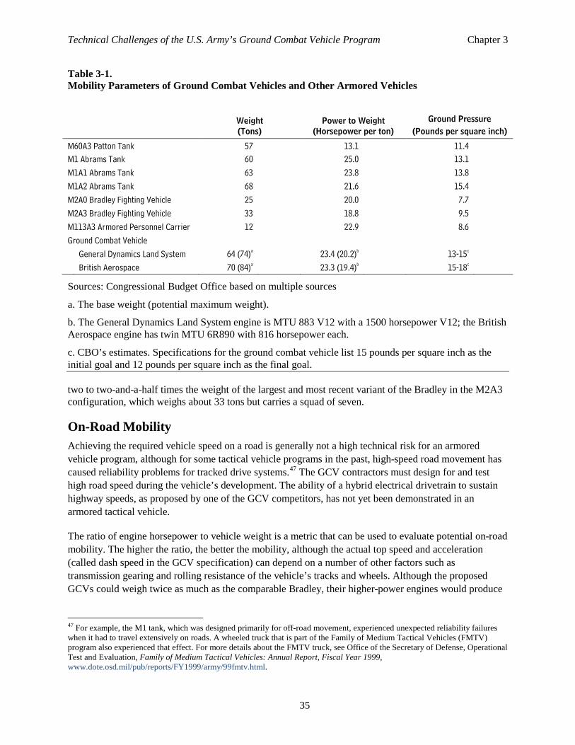
Technical Challenges of the U.S. Army’s Ground Combat Vehicle Program Chapter 3
35
Table 3-1. Mobility Parameters of Ground Combat Vehicles and Other Armored Vehicles
Sources: Congressional Budget Office based on multiple sources
a. The base weight (potential maximum weight).
b. The General Dynamics Land System engine is MTU 883 V12 with a 1500 horsepower V12; the British Aerospace engine has twin MTU 6R890 with 816 horsepower each.
c. CBO’s estimates. Specifications for the ground combat vehicle list 15 pounds per square inch as the initial goal and 12 pounds per square inch as the final goal.
two to two-and-a-half times the weight of the largest and most recent variant of the Bradley in the M2A3 configuration, which weighs about 33 tons but carries a squad of seven.
On-Road Mobility Achieving the required vehicle speed on a road is generally not a high technical risk for an armored vehicle program, although for some tactical vehicle programs in the past, high-speed road movement has caused reliability problems for tracked drive systems.47 The GCV contractors must design for and test high road speed during the vehicle’s development. The ability of a hybrid electrical drivetrain to sustain highway speeds, as proposed by one of the GCV competitors, has not yet been demonstrated in an armored tactical vehicle.
The ratio of engine horsepower to vehicle weight is a metric that can be used to evaluate potential on-road mobility. The higher the ratio, the better the mobility, although the actual top speed and acceleration (called dash speed in the GCV specification) can depend on a number of other factors such as transmission gearing and rolling resistance of the vehicle’s tracks and wheels. Although the proposed GCVs could weigh twice as much as the comparable Bradley, their higher-power engines would produce
47 For example, the M1 tank, which was designed primarily for off-road movement, experienced unexpected reliability failures when it had to travel extensively on roads. A wheeled truck that is part of the Family of Medium Tactical Vehicles (FMTV) program also experienced that effect. For more details about the FMTV truck, see Office of the Secretary of Defense, Operational Test and Evaluation, Family of Medium Tactical Vehicles: Annual Report, Fiscal Year 1999, www.dote.osd.mil/pub/reports/FY1999/army/99fmtv.html.
Weight (Tons)
Power to Weight (Horsepower per ton)
Ground Pressure (Pounds per square inch)
M60A3 Patton Tank 57 13.1 11.4 M1 Abrams Tank 60 25.0 13.1 M1A1 Abrams Tank 63 23.8 13.8 M1A2 Abrams Tank 68 21.6 15.4 M2A0 Bradley Fighting Vehicle 25 20.0 7.7 M2A3 Bradley Fighting Vehicle 33 18.8 9.5 M113A3 Armored Personnel Carrier 12 22.9 8.6 Ground Combat Vehicle General Dynamics Land System 64 (74)a 23.4 (20.2)b 13-15c British Aerospace 70 (84)a 23.3 (19.4)b 15-18c
Technical Challenges of the U.S. Army’s Ground Combat Vehicle Program Chapter 3
36
horsepower-to-weight ratios similar to those of the early generation of Abrams tanks and the M113A3 (see Table 3-1). By that measure, their road mobility should be comparable to the M1 tanks, but only if the weight advertised by the contractors does not grow, which it typically does in armored vehicle programs.
Off-Road Mobility With the intent of improving overall fleet survivability, the Army requires that the GCV be capable of extensive off-road mobility. Recent experience in Iraq and Afghanistan shows that traveling on roads increases the likelihood of being hit by IEDs. The more a vehicle can remain off road, the less likely it will be to encounter an IED. Staying completely off roads is impractical, particularly in urban operations, so this approach is only a partial solution to surviving IEDs.
Vehicle weight is not as big a concern in on-road movement, but it can be a limiting factor in off-road movement. Whether the GCV will have improved off-road mobility compared with that of the Abrams tank and the Bradley vehicle is hard to predict, as off-road mobility is a complicated issue with many variables to consider, especially the surface being traversed. Designers typically look at ground pressure—the weight of the vehicle divided by the contact surface area—as a general indicator of off-road mobility. The lower the ground pressure, the greater the off-road mobility. A GCV weighing 64 to 80 tons needs a ground pressure of 13.1 to 15.4 pounds per square inch to operate at the levels of current armored vehicles. The GCV specification lists 15 pounds per square inch as the threshold (the minimum acceptable level) for ground pressure and 12 pounds per square inch as the objective.
The Abrams tanks and Bradley vehicles ushered in an era of increased off-road mobility compared with that achieved by earlier U.S. Army armored vehicles. The improvement was achieved with high horsepower-to-weight ratios, low ground pressure, and improved suspension systems. The improved suspensions allowed drivers and crews to remain at tolerable levels of shock (that is, with less bouncing around inside) despite high cross-country speeds. Before this new era, Army tracked vehicles transmitted so much shock and energy to the crew that they voluntarily slowed down before reaching the mechanical limits of the vehicle.48 The Abrams and Bradley required heavier-duty drivetrain components because the smooth suspensions encouraged drivers to stress the mechanical limits of the drivetrain. The GCV will need a comparable suspension, but, by the Army’s assessment, such equipment is not beyond the current state of the art and thus is not a great technical risk.49
Transportability One of the great challenges in the FCS program was making the vehicle small and light enough to be transported on a C-130 Hercules cargo aircraft. The GCV program has avoided that problem by specifying the much larger C-17 Globemaster III and the C-5 Galaxy as the smallest aircraft on which the GCV must be capable of being transported.
48 Army vehicle testers characterize ride smoothness by measuring the power delivered to the vehicle at the driver’s seat. The GCV specification calls for no more than 6 watts delivered to the driver’s seat mounting point over a specified test course, a requirement comparable to that for the Abrams tank and Bradley fighting vehicle. 49 Fernandez, Frank, Independent Review Team Early Assessment of Technology Maturity for Ground Combat Vehicle (GCV), Office of the Deputy Assistant Secretary of the Army (Research and Technology), November 2009.
Technical Challenges of the U.S. Army’s Ground Combat Vehicle Program Chapter 3
37
Making the GCV transportable by rail and ship should not represent a technical risk, although the size of the GCV designs proposed by both contractors could restrict travel on some of the rail networks in less developed countries.
The Army will allow the GCV to be disassembled to some degree to prepare for air, rail, and sea transport, but it must be able to drive on and off the transport vehicle. It does not have to be in a “full combat capable state” during air, rail, or sea transport.50 Disassembly and reassembly can add hours of time to a deployment process, thus, the GCV cannot normally conduct forced-entry operations where the vehicle must fight as soon as it arrives at the transport destination.
Fuel Economy The Army expects the GCV to have improved fuel economy compared with that of existing armored vehicles. The contractors plan to fulfill that requirement by using new technology, such as hybrid electric power, high-efficiency diesels, and auxiliary power units for times when the vehicle must idle.
Hybrid electric power is a vehicle power train design that uses internal combustion engines to power electrical generators. They, in turn, power electrical motors that drive the tracks through one or more transmissions. The hybrid system may also include regenerative capability to capture waste energy from braking and store it in batteries, flywheels, or other mechanisms for reuse, which can increase the vehicle’s fuel efficiency. A distributed hybrid power system uses two smaller engines and generators instead of one larger engine and generator. It has the advantage in part-load situations—such as when the vehicle is stationary but has its radios and defensive and weapon systems working—because one of the engines can be turned off. The remaining single engine can run at a more efficient throttle setting as compared with a large engine running at a throttled-down setting to meet the reduced power demands.51
The extra weight of the GCV armor and electronic systems may negate gains in fuel economy achieved through advanced technology engines.52 The Army’s analysis of alternatives for the GCV showed that although the GCV should have more efficient engines than current vehicles have, the overall fuel use would be about the same as that of current vehicles because of the heavier weight of the GCV and the need to power more electrical systems on board.53 Given those conflicting factors, the actual fuel economy of the GCV will be established in testing under realistic conditions.
50 The GCV specification defines “full combat capable” as the state and condition of the GCV with all armor applied; a basic load of ammunition, fuel, and communication equipment; and 24 to 48 hours of supplies. Any loading short of that results in a lesser state called “essential combat configuration.” 51 The proposed BAE GCV would use a hybrid system with two 6.6 liter, 6-cylinder diesel engines, each powering an electrical generator. There are two electric motors and a transmission for propulsion in addition to a battery pack for storing electrical energy. The proposed GDLS GCV would not use a hybrid drive but instead would use a single high-efficiency V-12 engine (currently used on the Israeli Merkava tank) mated to a transmission and final drive. 52 Current Abrams tanks, which weigh about 68 tons, must refuel at least twice a day during high-tempo operations, requiring up to 500 gallons of fuel in each refueling. Thus, U.S. armored units must plan their missions around frequent fuel resupply. The high consumption of the Abrams tank is due partly to its weight and partly to its turbine engine. A typical M1 tank spends about 70 percent of the day with the engine idling to provide power for radios, sensors, and computers. By their innate design, turbine engines consume nearly as much fuel when idling as they do when at full power. A diesel engine can idle much more efficiently and burn less fuel. None of the GCV candidates is proposing turbine power. 53 Lambert, Garrett, et al., Ground Combat Vehicles Analysis of Alternatives: Executive Summary Briefing, Department of the Army, TRADOC Analysis Center, White Sands Missile Range, December 17, 2010.
Technical Challenges of the U.S. Army’s Ground Combat Vehicle Program Chapter 3
38
Fuel economy in armored vehicles is an important consideration not just because fuel is becoming more expensive but because delivering fuel in a conventional or unconventional combat environment has many other implied tasks and costs. The true cost of fuel consumption must incorporate the burden of transporting the fuel and keeping it secure. In a tactical environment, combat resources must be diverted to protect fuel convoys and depots. Calculating the cost of the resources required to move and protect the fuel is highly dependent on the scenario, but it is never insignificant. In counterinsurgency, attacks on convoys can lead to a large number of casualties. In Iraq, one out of eight U.S. casualties was the result of protecting convoys and trucks, 85 percent of which carried fuel.54 In Afghanistan the casualty rate for protecting fuel convoys has been about double that in Iraq.55
Shoot Although it is an armored vehicle, the GCV is not a main battle tank with large-caliber cannon. The GCV specification calls only for a small-caliber weapon for infantry support. Several existing gun systems can meet that specification. Both of the GCV proposals that the Army selected include existing gun systems to meet the requirement.
The Army has decided to make an antitank guided missile a tradable option in the GCV program, which reduces the system’s cost and complexity. It also removes a significant vulnerability: The exposed missile launchers can cause damage to the vehicle if they are hit by enemy fire.
The GCV specification includes nonlethal weapon options onboard, but they are not a part of the Army’s Big Four requirements and can be traded for other capabilities.
Communicate Communications capability is the final basic function of a combat vehicle. It encompasses both the radios and the sensors used to provide inputs to the communications, weapon, and defensive systems.
Communications for the GCV are to be provided by the GCV Network Integration Kit. The GCV vendor is not to be responsible for developing the kit; instead, the Army has decided that it will be provided as government-furnished equipment. The Network Integration Kit encompasses more than two-way radio communications. It is a layered system of computers, software, and radios that enhances situational awareness by taking communications and sensor data and fusing that information to provide a common operating picture of the battlefield. The Network Integration Kit was previously integrated and tested on MRAP vehicles and on high mobility multipurpose wheeled vehicles (HMMWVs).
Communications requirements for the GCV mainly focus on capabilities to be provided by the Network Integration Kit. The kit is meant to allow the GCV, when it is on the move, to communicate securely with other vehicles and dismounted soldiers in the force. Beyond radio communications, the Network 54 Hargreaves, Steve, “For the Military Clean Energy Saves Lives”, CNN Money, August 17, 2011, http://money.cnn.com/2011/08/17/technology/military_energy/index.htm. 55 The casualty factor for fuel resupply in Afghanistan is 0.042—that is, 0.042 casualties for every fuel-related resupply convoy or 1 casualty for every 24 fuel resupply convoys. In Iraq, the comparable number was 0.026. Eady, David S., et al., Sustain the Mission Project: Casualty Factors for Fuel and Water Resupply Convoys—Final Technical Report, Army Environmental Policy Institute, Arlington, VA, September 2009.
Technical Challenges of the U.S. Army’s Ground Combat Vehicle Program Chapter 3
39
Integration Kit is also intended to provide target-tracking capability, perform battle damage assessments, exchange information over secure networks with other systems, and survive specified nuclear and electromagnetic pulse events.
Although GCV vendors are not responsible for developing the Network Integration Kit, the scope of the capabilities required in that system as well as the requirement that it should not interfere with the performance of other systems on board the GCV indicates that close coordination between the government and the GCV vendor will be necessary to ensure the kit’s successful integration into the GCV. Previous network-based communication systems, such as the Joint Tactical Radio System, suffered from cost overruns and performance problems.
The GCV performance specifications contain requirements for a range of sensors, reflecting the current state of the art in sensor technology. Sensor capability encompasses threat detection, situational awareness, and command and control.
Following the cancellation of the FCS program, driven in part by concerns about the number of immature technologies that were being developed as part of the program, the Army stated that the GCV program would focus on mature, proven technologies. Several of the sensor technologies identified for the GCV are quite mature (variants of the hand-held Joint Chemical Agent Detector have been fielded for over a decade, for example), but the sensor technologies required to detect other threats are not nearly as mature. Large investments have been made in sensors to detect improvised explosive devices, and several systems have been fielded, but the current capability to detect emplaced devices in real time while traveling at road speeds is still limited. In addition, the capability to detect and identify enemy munitions—especially in time to take evasive action—still requires technology development.
Cost Overall system cost is a key parameter in the GCV program. The Army placed cost caps on the vehicle as described earlier. Nevertheless, most components of the GCV will cost more than they did for the Stryker and Bradley (see Table 3-2). Specifically, the engine and fuel, chassis and suspension, communication and navigation, survivability armor, and survivability electronics systems of the GCV will cost more than such systems on the Bradley and the Stryker.
The armor and defensive electronic systems are the most expensive components on the GCV, representing nearly one-third of the vehicle’s overall cost. The GCV’s armor components cost five times more than the Bradley’s armor and about 10 times more than the Stryker’s. The Bradley and Stryker did not have any significant costs for survivability electronic systems, whereas the Army expects those electronics (which include the active protection and soft-kill systems) to cost about $0.8 million on the GCV. That estimate is likely to go up, given the recent Department of Defense (DoD) tests that showed more work is necessary to develop and field the active protection systems that drive this cost.
The higher cost of the GCV armor is largely due to the amount of ceramic material used in the modular system. Ceramics are more difficult than traditional bulk armor to manufacture and thus require more labor to assemble. They may also use expensive materials both in the ceramic inserts and in the supporting structure. For example, some of the proposed GCV armor designs use titanium to encase and
Technical Challenges of the U.S. Army’s Ground Combat Vehicle Program Chapter 3
40
support the ceramic, and titanium is more expensive than steel.56 The ceramic materials themselves are more expensive than steel, but they are more efficient at protecting the vehicle than is steel of the same weight. Ceramic armor materials can halve the weight per unit of protected area of armor compared with the same metric for steel, but they cost 4 to 12 times as much to achieve that benefit.57
To reduce costs, the Army has allowed the vehicle designers to omit some capabilities in the GCV that are included in the Bradley. For example, the Bradley has a long-range antitank missile launcher and associated long-range sensors mounted on the turret. Those components contribute about $1.3 million, or 35 percent, of the overall Bradley manufacturing cost of $3.9 million. The Army expects to save some money by omitting the missile launcher on the GCV, but the overall armament and sensor costs for the vehicle (about $1.4 million) will still be greater than those for the Bradley.
The Army predicts that sensors will make up a smaller fraction of the overall cost of the GCV compared with their share of the cost of the latest version of the Bradley. Sensors will contribute about 12 percent of the GCV’s $9.1 million manufacturing cost, whereas they contribute 29 percent of the Bradley M2A3’s $4.0 million cost. The latest versions of both the Abrams and Bradley have dual infrared sensors on independent mounts. Those expensive but capable sensors allow the crews to search a wider area than previous versions of the Abrams and the Bradley. Operational testing showed that they improved combat capability in some missions.58
56 Titanium costs more than steel initially, but in some applications its resistance to corrosion and high temperatures may lead to some maintenance savings in the long run. Montgomery, Jonathan S., et al., Low-Cost Titanium Armors for Combat Vehicles, JOM (Journal of the Minerals, Metals, and Materials Society), vol. 49, no. 5, 1997, pp. 45–47. 57 The defense community uses the term “areal density” to describe that parameter. Hazell, Paul, Ceramic Armour: Design and Defeat Mechanisms, Canberra, Australia, Argos Press, January 2006. 58 Department of Defense, Director of Operational Testing, “Bradley Fighting Vehicle System Upgrade-A3,” 2002 Annual Report, 2002, www.dote.osd.mil/pub/reports/FY2002/pdf/army/2002BradleyFVSUpgrade-A3.pdf.
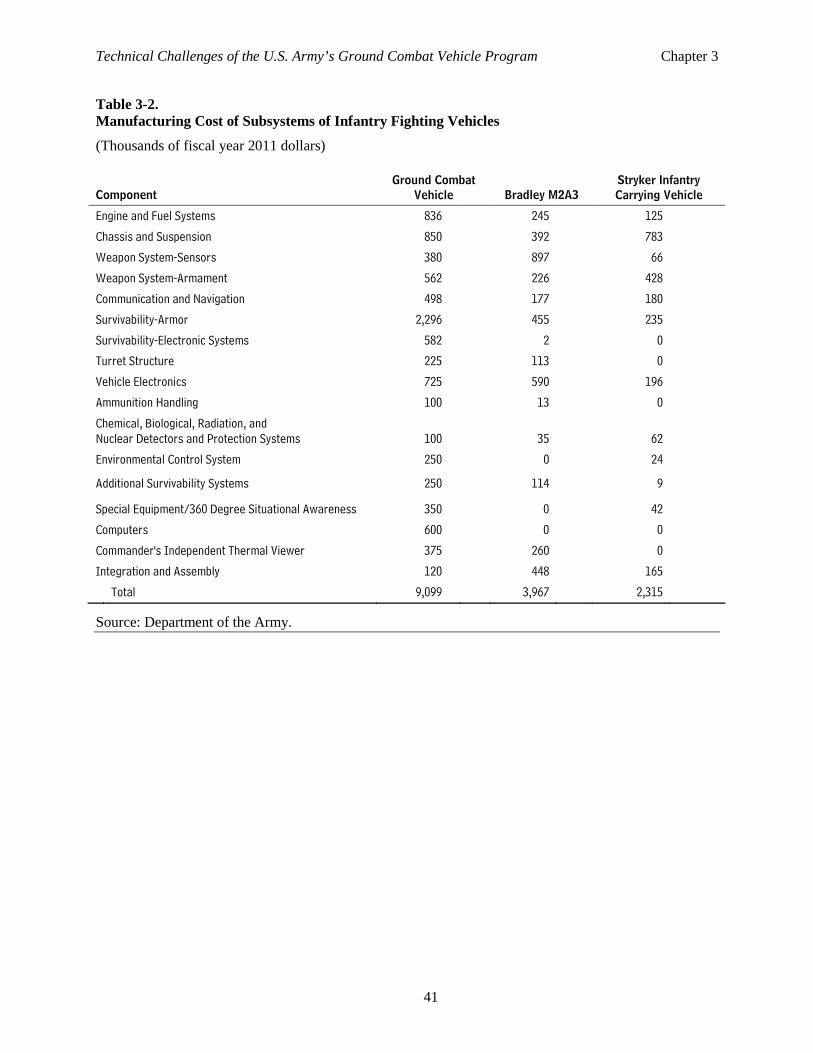
Technical Challenges of the U.S. Army’s Ground Combat Vehicle Program Chapter 3
41
Table 3-2. Manufacturing Cost of Subsystems of Infantry Fighting Vehicles
(Thousands of fiscal year 2011 dollars)
Component Ground Combat
Vehicle Bradley M2A3 Stryker Infantry Carrying Vehicle
Engine and Fuel Systems 836 245 125
Chassis and Suspension 850 392 783
Weapon System-Sensors 380 897 66
Weapon System-Armament 562 226 428
Communication and Navigation 498 177 180
Survivability-Armor 2,296 455 235
Survivability-Electronic Systems 582 2 0
Turret Structure 225 113 0
Vehicle Electronics 725 590 196
Ammunition Handling 100 13 0
Chemical, Biological, Radiation, and Nuclear Detectors and Protection Systems 100 35 62
Environmental Control System 250 0 24
Additional Survivability Systems 250 114 9
Special Equipment/360 Degree Situational Awareness 350 0 42
Computers 600 0 0
Commander's Independent Thermal Viewer 375 260 0
Integration and Assembly 120 448 165
Total 9,099 3,967 2,315
Source: Department of the Army.

Appendix A. Recent Army Combat Vehicle Development In the 1980s, the U.S. Army modernized its mechanized forces with the M1 Abrams tanks and M2 Bradley Infantry Fighting Vehicles. Those vehicles represented major leaps in capability and cost over the vehicles they replaced (see Figure 3-6). Instead of being just a lightly armored infantry carrier, the Bradley was a true fighting vehicle with a 25 millimeter cannon and an antitank missile system mounted on a turret. Later versions included two independent second-generation infrared sensors, computerized command-and-control systems, heavier armor, and more powerful engines. The current Bradley has evolved into a highly capable vehicle that, at 33 tons, is heavier than most tanks from the World War II era. As demonstrated in the first and second Gulf Wars, this Abrams-Bradley combined arms force is highly effective in conventional mechanized combat.
Those improvements, however, came with a cost. The increased weight of the Bradley and Abrams mechanized force restricted its transportability and its ability to move over roads and bridges in some combat theaters. In addition, its high fuel consumption constrained its operational flexibility and required more logistics support than more fuel-efficient forces. In the 1990s, the Army engaged in a continuing series of peacekeeping and smaller-scale operations against unconventional and irregular forces, in which, for the reasons stated above, some viewed heavy armor as a liability.
In response, the Army undertook an accelerated acquisition program to buy the lighter, more mobile, and less protected Stryker family of medium-armored vehicles, which are optimized for the smaller-scale missions but ostensibly maintain some capability for major theater-level warfare if augmented with heavier support forces.1 Those eight-wheel-drive armored vehicles have been used extensively in Iraq and, to a lesser extent, in Afghanistan to support U.S. mechanized infantry. However, the vehicles’ medium armor was not as effective in dealing with the threat of improvised explosive devices (IED) that the enemy developed in those conflicts, especially explosively formed penetrators.2
To address the rapidly emerging threat from IEDs, the Army (and the Marine Corps) sought an off-the-shelf vehicle for immediate use in Iraq and Afghanistan. The Mine Resistant Ambush Protected (MRAP) program spent more than $44 billion to field about 26,500 armored wheeled vehicles, most intended to replace high-mobility multipurpose wheeled vehicles (HMMWVs). Six different contractors provided more than 100 different variants of MRAP vehicles to the program.3 Those vehicles provided more protection against IEDs than do the vehicles in the existing wheeled-vehicle fleet of HMMWVs and cargo trucks, but the Army believes that the MRAP vehicles fell short of being true multipurpose combat vehicles because they had little off-road mobility and insufficient protection against weapons carried by opposing mechanized forces in a more conventional conflict.4
1 Townsend, Stephen J., Alternative Organizations for Interim/Stryker Brigade Combat Teams, U.S. Army War College, Carlisle Barracks, PA, July 4, 2003. 2 Duma, David W., “Testimony before the Senate Committee on Armed Services, Subcommittee on Air Land,” April 15, 2010, p. 53. 3 Hansen, Dave, “Joint Program Office Mine Resistant Ambush Protected Vehicles,” JPO MRAP Program Manager, undated. www.dtic.mil/ndia/2011tactical/TuesdayMRAPpanel900.pdf. 4 United States Army, “Executive Summary Briefing, Ground Combat Vehicle (GCV) Analysis of Alternatives”, 17 December, 2010.
Technical Challenges of the U.S. Army’s Ground Combat Vehicle Program Appendix A
44
With none of its existing vehicles adequate for the range of conflicts it expected to fight, the Army turned to the Future Combat Systems (FCS) program. It was the immediate predecessor the Ground Combat Vehicle (GCV) program, although the Army had been working on developing a new family of ground vehicles since the mid-1980s, beginning with the Heavy Force Modernization Program and the later Armored System Modernization programs.5
For close to a decade, the Army’s FCS acquisition program embodied the Army’s goal of developing a more agile, flexible, and deployable force to confront threats worldwide while maintaining the combat power of the Army’s Cold War-era forces. The Army originally conceived the program to shift the service’s existing force, which was organized around divisions, into one designed around brigade-sized units equipped with networked technologies, the intent being that a smaller, lighter force with superior battlefield awareness would be able to outmaneuver and defeat a larger, heavier one. The Army’s original aim was to field 15 brigade combat teams equipped with new manned ground vehicles and an array of communications, sensor, and unmanned technologies by fiscal year 2025.6 The cost estimate for the overall program—research and development as well as procurement—was $89.8 billion (in 2009 dollars) at the beginning of the program in 2003.
The manned ground vehicles were to be a family of lightweight tactical vehicles built around a common tracked platform and capable of supporting upgrades in sensors, communications, and protection. Variants were to include a recovery and maintenance vehicle, an infantry carrier vehicle, a medical vehicle, and a non-line-of-sight cannon and mortar.
The manned ground vehicle was to introduce new capabilities into the Army. It was to be the first ground combat vehicle to use electrical propulsion and would have the ability to generate 420 kilowatts* of electrical power, providing power not only for propulsion but also to support a complex array of electronic systems on board the vehicle. 7 In addition, FCS vehicles were to feature signature-reducing technology and lightweight armor consisting of titanium, high-strength aluminum, polymer composites, and ceramics. The lightweight armor would provide significant protection while still being light enough to allow the vehicle to be transported on the C-130 Hercules cargo aircraft. All vehicles were to have a tactical internet to allow continuous communications among vehicles and tracking of potential targets and friendly forces. [*After original publication, unit of measure corrected on November 20, 2012]
The FCS’s Infantry Carrier Vehicle, the infantry variant of the manned ground vehicles, was to carry 11 soldiers: the vehicle commander, the driver, and a 9-soldier infantry squad. The Infantry Carrier Vehicle program was just one of eight new manned armored vehicles planned for the FCS; the program also included four classes of unmanned aerial vehicles, three types of unmanned ground vehicles, several unattended ground sensors, a missile launcher, and a new munitions system—all of which would be linked by an advanced communications network into an integrated combat “system of systems.”8
5 Demma, Vincent, Historical Summary: FY 1989, Chapter 11, Modernization: Research, Development, and Acquisition, United States Army Center of Military History, p. 213. www.history.army.mil/books/DAHSUM/1989/CH11.htm. 6 For a more detailed discussion of the FCS program, see Andrew Feickert and Nathan Jacob Lucas, Army Future Combat Systems (FCS) “Spin-Outs” and Ground Combat Vehicle (GCV): Background and Issues for Congress, Report for Congress RL32888 (Congressional Research Service, November 30, 2009); and Congressional Budget Office, The Army’s Future Combat Systems Program and Alternatives, August 2006. 7 The FCS vehicles were the first U.S. combat vehicles that planned to use a hybrid electric power train, though the hybrid electric power technology has been used by railroad locomotives and off-road construction equipment for many decades. 8 Congressional Budget Office, The Army’s Future Combat Systems Program and Alternatives, August 2006, p. 21.
Technical Challenges of the U.S. Army’s Ground Combat Vehicle Program Appendix A
45
Initial contracts for the FCS were issued in 2003. Over the next several years, the program was restructured several times. One of the first major changes from the program as originally envisioned in 1999 occurred in 2003 with a shift toward spiral development, where functional FCS capabilities would be incorporated as they became available to accelerate fielding of FCS technologies before 2014. In 2007, reflecting budgetary constraints in the program, the Army cut four systems and slipped the schedule for the FCS Brigade Combat Team Milestone C, which involved initial operational capability and full operational capability within six months. On June 24, 2008, the Army issued a stop-work order for the manned ground vehicles, and on July 20, 2008, the Army announced the partial termination of the manned ground vehicle development effort.
Beginning in 2006, the Government Accountability Office (GAO) was tasked by Congress to issue an annual report on the FCS program. By 2009, GAO had found that although the Army clearly needs to be well equipped and the FCS program contained a number of promising elements that should be considered in future equipping efforts, the program faced fundamental obstacles.9 According to GAO, the FCS program was “very immature when it began, and was not executable within reasonable bounds of technical, engineering, time, or financial resources.”
Comparing metrics for the program from when it began in 2003 to when it was ended in 2009, GAO noted the following:10
• Initial cost estimates had increased from $89.8 billion to $159.3 billion in FY2009 dollars over 6 years, even after several changes to the program that were designed to save money;
• There were persistent gaps in requirements for the program; and
• The schedule from the start of development to initial operational capability slipped from 7-1/2 years to more than 12 years, and the maturity date of critical technologies in the program slipped by 3 years.
Following the cancellation of the FCS program, then-Secretary of Defense Robert Gates addressed some of the reasons behind his decision.11 While noting that some components produced by FCS have demonstrated adaptability and relevance, he stated that underlying assumptions that were built into the system from the beginning of the program had been refuted by subsequent experiences in Iraq and Afghanistan. In terms of the manned ground vehicles, those experiences added complexities that led to fundamental design issues. Secretary Gates specifically noted that the premise behind the design of FCS vehicles—that lower weights, greater fuel efficiency, and near-total situational awareness would compensate for less heavy armor—ran up against the realities of close quarters combat and more lethal forms of ambush faced by U.S. troops engaged in combat in Southwest Asia over the past decade. For example, as underbelly attacks against combat vehicles became a threat in Iraq and Afghanistan, the design of the manned ground vehicles—which initially had a flat bottom and an 18-inch ground clearance—was reworked to incorporate a V-shaped hull, a design intended to protect against such 9 Government Accountability Office, Defense Acquisitions: Issues to be Considered for Army’s Modernization of Combat Systems, GAO-09-793T, June 16, 2009, www.gao.gov/products/GAO-09-793T. 10 Government Accountability Office, Defense Acquisitions: Opportunities Exist to Position the Army’s Ground Force Modernization Efforts for Success, GAO-10-406, March, 2010, www.gao.gov/products/GAO-10-406. 11 Office of the Assistant Secretary of Defense (Public Affairs), Remarks by Secretary of Defense Robert Gates at the Army War College, Carlisle, PA, April 16, 2009.
Technical Challenges of the U.S. Army’s Ground Combat Vehicle Program Appendix A
46
threats. Likewise, the manned ground vehicle’s chassis was initially designed to support a 30-ton vehicle. However, as attacks using IEDs and other weapons against combat vehicles increased in Iraq and Afghanistan, more armor was built into the design until overall vehicle weights in some cases increased by more than 25 percent.
While noting those problems with the FCS program in general and the manned ground vehicles specifically, Secretary of Defense Robert Gates did go on to say that the Army needed a modernized fleet of combat vehicles to replace the Cold War inventory. Following the cancellation of the FCS program, Secretary Gates directed the Army to reevaluate the requirements, technology, and approach of its vehicle modernization program.12 The Army concluded that the need existed for a new ground combat vehicle existed based on the following conclusions:
• Improvements in soldier protection against casualties resulting from IED attacks come at the cost of tactical and operational mobility of existing vehicles. A new combat vehicle that has the versatility to incorporate those improvements is therefore needed.
• Fundamental limitations in the architecture of today’s combat vehicles—most of which were designed in the 1970s, prohibit introduction of new technologies and capabilities. That includes not only electronic systems but improvements in survivability, crew capacity, and fuel efficiency.
• For more than a decade, U.S. troops—and their equipment—have been engaged in combat missions in Afghanistan and Iraq. The added impact on the life cycles of combat vehicles that were already approaching 20- to 30-year operational lives has been significant. For example, the Army Capabilities Integration Center noted that prior to operations in Iraq, a Bradley fighting vehicle required new tracks once every year. In 2003, extensive use of those vehicles led to their requiring new tracks every 60 days at a cost of more than $22,000 per vehicle. Restoring the vehicles when they return to the United States (a process the Army calls resetting) addresses some worn components but cannot completely bring back the overall system to a like-new status, in the Army’s view.13
In addition, the Army noted that the development timelines for the Bradley fighting vehicle, the Abrams tank, and the Paladin artillery delivery system all exceeded 10 years. Improvements to the Army’s acquisition process center around improvements to timelines for developing new systems. Realistic and achievable requirements, creativity in achieving programmatic goals and timelines, and the building-in of flexibility to account for novel threats or improvements in technology during the development process, as well as after fielding, have been stressed as areas to improve the overall weapon system development process.14 It was with those issues in mind that the Army determined that having a shorter development timeline that still allows for the fielding of an effective system is one of the main goals for the development of a next-generation fighting vehicle.
12 Vane, Lt. Gen. Michael A., Why Army Needs New Combat Vehicle, The Hill, January 25, 2010, http://thehill.com/opinion/ op-ed/77883-why-army-needs-new-combat-vehicle. 13 Ibid. 14 See, for example, Department of the Army , Army Strong: Equipped, Trained and Ready, Final Report of the 2010 Army Acquisition Review, January 2010.
Appendix B. Shaped Charges, Improvised Explosive Devices, and Reactive Armor
Shaped charges and improvised explosive devices (IEDs) have become common threats in modern combat. Insurgents have made extensive use of them against the United States in Iraq and Afghanistan over the past decade, and they were used to great effect by Hezbollah in 2006 against the Israelis in Lebanon. Armor designers have been working on solutions to shaped-charge weapons for decades, the most notable of which is reactive armor, which has been applied to U.S. combat vehicles primarily in the side quadrants. However, the ability of insurgents to attack armored vehicles with shaped-charge weapons and IEDs from all directions, including under the vehicles’ bodies, has forced designers to rethink how best to protect soldiers and crews in combat vehicles.
What Is a Shaped Charge? The shaped charge traces its origins to the Munroe Effect discovered in 1885, but the concept may have been used earlier by miners. Henry Mohaupt, a Swiss chemical engineer, invented the lined shaped charge in 1935 with the intent to create an infantry-portable antitank weapon. The technology became widespread during World War II as the United States, Britain, Russia, and Germany all developed weapons with shaped-charge warheads. The U.S. Bazooka, German Panzerfaust/Panzershreck, British PIAT, and Russian rocket-propelled grenade (RPG) were early examples of shaped charges used in antitank weapons. Continuously improved since then, the shaped charge is the heart of many antitank munitions today, including antitank guided missiles, the ubiquitous RPG-7s, and some mines.
Generally, a shaped charge is an explosive device with a cavity that focuses the blast into a small area. In military applications, a shaped charge consists of a concave metal hemisphere or cone (also known as a liner) backed by high explosives in a casing with a detonator in the rear (see Figure B-1). The detonator ignites the explosives, creating a blast wave that hits and deforms the liner to form a projectile.
The two primary forms of military shaped charges are the high explosive antitank (HEAT) round and the explosively formed projectile (EFP). HEAT and EFP shaped charges use similar overall designs— an explosive fill and a metallic liner (see Figure B-2). The angle of the liner (the so-called cone angle) is the primary design difference; it affects the way the blast wave from the explosive interacts with the liner and forms either a jet (in the case of a HEAT warhead) or a slug (in the case of an EFP; see Figure B-3). Liners with steep cone angles form both jets and slugs, but shallow cone angles create only slugs.
High Explosive Antitank Shaped Charges The steep conical design of the HEAT shaped-charge liner focuses the effect of the explosive’s energy to form a shock wave that squeezes the metallic liner so that it emerges from the front of the charge in a hypervelocity jet. The shock wave accelerates the liner at about 25 million times the acceleration of
Technical Challenges of the U.S. Army’s Ground Combat Vehicle Program Appendix B
48
Figure B-1. Typical Rocket-Propelled Antitank Shaped-Charge Weapon: A U.S. M72 62 millimeter Light Antitank Weapon Showing the Location of the Shaped-Charge Cone in Relation to the Fuze and Nose Cap Initiator
Source: U.S. Army, General Ammunition, TM 9-1300-200, p. 199.
gravity. The jet resembles a thin stream of metal with a tail end that is more coarsely formed and slower moving. That tail end is called the slug.
The jet is solid metal. It is not molten, nor is it a gas or plasma. It does not burn through the armor but rather penetrates armor via mechanical erosion and shock. The high velocities and energy involved in the interaction of the jet with the target exert forces that greatly exceed the strength of the jet and the armor materials. The jet and the armor thus behave as liquids even though they are below the melting temperature of the metal.1
1 The designers exploit this phenomenon and use computer models called hydrocodes to study the interaction of jets and armor. Hydrocodes derive their name because they originally were developed to study fluid flows.
Technical Challenges of the U.S. Army’s Ground Combat Vehicle Program Appendix B
49
Figure B-2. Cross Sections of a High Explosive Antitank-Shaped Charge and an Explosively-Formed Penetrator-Shaped Charge Showing the Difference in Their Cone Angles
Source: Congressional Budget Office.
The jet can penetrate deeply into armor, and engineers use the initial cone diameter as a metric for the shaped charge’s penetration. The normal penetration distance into regular steel armor is 2 to 6 times the diameter of the HEAT liner’s cone, but in modern, well-built designs, the jet can go as deep as 11 to 12 times the cone diameter.
The velocity of the tip of the jet is about 10 kilometers per second, but the slug moves at about 2 kilometers per second. Thus, the jet quickly elongates after it forms. Aerodynamic drag will act on the particles in the jet and cause them to decelerate and spread out, making the tip of the jet slower and wider. It will quickly lose its penetration power as it decelerates and disperses, though it still poses a hazard to unprotected personnel for a great distance from the point of detonation.
The jet must have some time and distance to form before it hits the armor but not so much that its penetration power is adversely affected by aerodynamic drag. Optimum penetration occurs when there is optimum jet elongation (see Figure B-4). To provide the time for optimum elongation, designers include a physical gap between the warhead tip and the liner. That gap is called the standoff distance. For any given HEAT shaped charge, there is an optimum standoff distance that provides optimum jet elongation. Many modern HEAT warheads have extending probes to improve the standoff distance and thus the warhead’s performance.
Too much standoff distance can, however, degrade the weapon’s effectiveness. In World War II, moderate standoff distance defeated the jet because shaped charges in that era were not as precisely made
Technical Challenges of the U.S. Army’s Ground Combat Vehicle Program Appendix B
50
Figure B-3. Effect of Shaped-Charge Cone Angles on Jet and Slug Formation
Source: W.P. Walters and J.A. Zukas, Fundamentals of Shaped Charges, John Wiley & Sons, New York, 1989.
Note: All images approximately 35 microseconds after detonation.
as current charges are, thus they decelerated and dispersed quickly. Adding light armor plates as armor appliqués—or even adding bedsprings, as the Russians did near the end of the war—a few feet from the armor’s surface was successful in defeating those early HEAT warheads. However, modern HEAT shaped charges behave differently and require large standoff distances before they degrade. It is usually impractical to add sufficient standoff distance to armor designs to degrade modern shaped charges. In fact, some standoff armor designs, such as designs added by soldiers in the field, may actually increase penetration because they provide extra standoff distance to allow better jet formation.
A HEAT jet tends to create a single deep but narrow hole in the attacked armor. The exit hole caused by the jet usually exhibits a narrow cone of spall (the material ejected from the penetration hole by the incoming projectile). Many times, the spall can increase the damage from an antitank round because it acts like a shotgun blast inside the target. Kinetic-energy rounds tend to create wider spall cones, which is one reason why kinetic-energy rounds can be so lethal to an armored vehicle. HEAT rounds, with their narrow spall cones, produce less damage as a result of spall, although the jet can continue to penetrate objects and armor if the initial armor is overmatched.
Technical Challenges of the U.S. Army’s Ground Combat Vehicle Program Appendix B
51
Figure B-4. The Typical Effect of Standoff on Penetration of Notional Shaped-Charge Warheads
Source: Congressional Budget Office based on multiple sources.
Notes: The penetration and standoff distances are notional.
HEAT = high explosive antitank warhead, EFP = explosively formed penetrator warhead.
Explosively Formed Penetrators When the liner–cone angle is broad, the resulting projectile is not a jet but a slug. That projectile is called an EFP and is also known as a self-forging warhead or a self-forging fragment (see Figure B-5). The slug does not have the same velocity as the tip of a HEAT warhead jet. Typically, the velocity is around 1 kilometer to 3 kilometers per second, or about the speed of a modern kinetic-energy projectile, which travels up to 1.5 kilometers per second.
The slugs do not have the same erosive effect on armor that the HEAT jet has. Instead, they rely on mass and shock to cause damage and can penetrate armor that is one to two times the thickness of the cone’s diameter. If a slug penetrates, it can create a larger penetration hole than can a jet, which creates more spall and thus more behind-armor damage.
Because it does not form a jet, the EFP is less sensitive to standoff distances. The slug is effective over a long distance until aerodynamic drag slows it down. Careful design and construction can create an EFP with a very low drag shape.2 Cruder EFPs found in IEDs tend to be less aerodynamic and may also break into multiple smaller slugs and fragments. However, EFPs with multiple fragments may have more points
2 For example, see the finned EFP design in Florence, Alex L., et al., Dynamic Plastic Buckling of Copper Cylindrical Shells, Poulter Laboratory, Physical Science Division, SRI International, Menlo Park, CA, 1989.
Technical Challenges of the U.S. Army’s Ground Combat Vehicle Program Appendix B
52
Figure B-5. U.S. Army Soldiers Empty a Massive Weapons Cache That Was Discovered at Saada Village, Iraq, on October 23, 2007
Source: Department of Defense, “Citizen Tip Leads to Massive EFP, Explosives Cache,” American Forces Press Service, www.defense.gov//News/NewsArticle.aspx?ID=47945. Photograph by Air Force Staff Sgt. Dennis J. Henry, Jr.
Note: The large flat conical plate will become the slug-forming liner for an explosively formed penetrator warhead. The casing, detonator, and explosive are yet to be added to the liner to make a complete weapon.
of impact on the outside of the target, albeit with less penetration capability per fragment. The analogy to a shotgun blast is appropriate.
Essentially, an EFP trades the deep penetration depth over a narrow range of standoff distances characteristic of a HEAT round for shallow penetration over a wider range of standoff distances. That makes EFPs very effective against lighter vehicles and armor, especially in off-route IEDs where standoff distance can vary widely.
Technical Challenges of the U.S. Army’s Ground Combat Vehicle Program Appendix B
53
Improvised Explosive Devices An IED is a bomb that is fabricated in an improvised manner; incorporates destructive, lethal, noxious, pyrotechnic, or incendiary chemicals; and is designed to destroy or incapacitate personnel or vehicles. The term “improvised explosive device” comes from the British Army and its 1970s struggle with the Irish Republican Army, although the same types of devices under different names were used in several wars prior to that one, including World War II and, extensively, the Vietnam War.3 IEDs may incorporate military or commercially sourced explosives, or, in many instances, both. They may also be made with homemade explosives. They may use shaped charges, especially EFPs, or blast or fragmentation warheads, depending on the intended target.
The wars in Iraq and Afghanistan underscored the devastating effect that well-placed IEDs could have on all of the military’s road vehicles and their crews. Given the potential for catastrophic damage from those devices to a vehicle and its crew, the IED threat itself had an impact on tactics, techniques, and procedures for the military, both when soldiers were on foot and in vehicles. Vehicle speeds dropped precipitously as the IED threat became apparent because crews attempted to visually inspect roadways for indications of an emplaced IED. In addition, crews and vehicles were developed and dispatched with the specific purpose of performing route clearance of emplaced IEDs. The impact of both of those changes on the operational tempo of troops confronting the IED threat remains significant.
In addition to affecting tactics, techniques, and procedures, the IED threat has had a significant impact on the design of military vehicles. The wars in Iraq and Afghanistan saw the development and introduction of a new class of armored vehicle, the mine resistant ambush protected (MRAP) vehicle. In addition to increased armor, the MRAP vehicle incorporates design features intended to minimize the damage from an IED. Some include V-shaped hulls, ostensibly to deflect the blast from an IED implanted below the vehicle, while also increasing the amount of armor the explosive fragments must penetrate in order to breach the vehicle. Other design features include modifications to crew seating to minimize the effects of blast shock waves within the vehicle, particularly the possibility of traumatic brain injuries and injuries to crew members’ extremities.
In addition to physical improvements to road vehicles that are intended to increase survivability, the United States developed other systems to counter IEDs as the devices became more sophisticated. As the initiating devices shifted from command wire to remote control, the United States military developed a series of electronic jammers (under the general heading of counter radio electronic warfare, or CREW) mounted on ground vehicles. Also mounted on the front of vehicles was a series of devices designed to set off thermal-based IED initiators before the vehicle entered the IED “kill zone.” There were also efforts aimed at detonating IEDs before the target vehicle arrives through a series of thermal, electronic, and optical devices.
The United States also invested significant resources in sensors designed to detect hidden IEDs in or by roadways. Those sensors use radar and electro-optical devices in an attempt to detect the IED itself or indicators associated with the emplacement of the devices such as displaced soil from burying an IED. Several of those efforts proved impractical or simply did not work; however, the ability to detect
3 Use of IEDs by the Irish Republican Army is discussed in Zorpette, Glenn, Countering IEDs, IEEE Spectrum, September 2008, http://spectrum.ieee.org/aerospace/military/countering-ieds/. The use of improvised explosives by partisans in Russia in World War II is described in Sigaltchik, Yakov, Memoires of a Partisan, www.jewishgen.org/yizkor/dokshitsy/dok274.html.
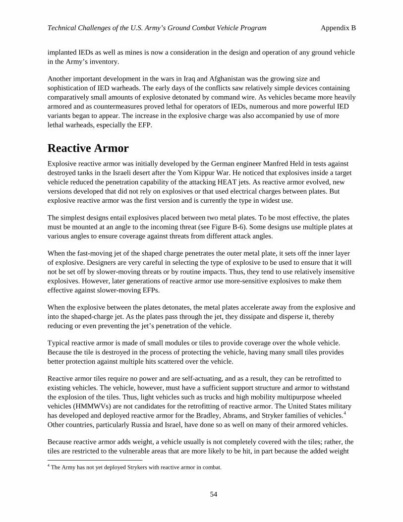
Technical Challenges of the U.S. Army’s Ground Combat Vehicle Program Appendix B
54
implanted IEDs as well as mines is now a consideration in the design and operation of any ground vehicle in the Army’s inventory.
Another important development in the wars in Iraq and Afghanistan was the growing size and sophistication of IED warheads. The early days of the conflicts saw relatively simple devices containing comparatively small amounts of explosive detonated by command wire. As vehicles became more heavily armored and as countermeasures proved lethal for operators of IEDs, numerous and more powerful IED variants began to appear. The increase in the explosive charge was also accompanied by use of more lethal warheads, especially the EFP.
Reactive Armor Explosive reactive armor was initially developed by the German engineer Manfred Held in tests against destroyed tanks in the Israeli desert after the Yom Kippur War. He noticed that explosives inside a target vehicle reduced the penetration capability of the attacking HEAT jets. As reactive armor evolved, new versions developed that did not rely on explosives or that used electrical charges between plates. But explosive reactive armor was the first version and is currently the type in widest use.
The simplest designs entail explosives placed between two metal plates. To be most effective, the plates must be mounted at an angle to the incoming threat (see Figure B-6). Some designs use multiple plates at various angles to ensure coverage against threats from different attack angles.
When the fast-moving jet of the shaped charge penetrates the outer metal plate, it sets off the inner layer of explosive. Designers are very careful in selecting the type of explosive to be used to ensure that it will not be set off by slower-moving threats or by routine impacts. Thus, they tend to use relatively insensitive explosives. However, later generations of reactive armor use more-sensitive explosives to make them effective against slower-moving EFPs.
When the explosive between the plates detonates, the metal plates accelerate away from the explosive and into the shaped-charge jet. As the plates pass through the jet, they dissipate and disperse it, thereby reducing or even preventing the jet’s penetration of the vehicle.
Typical reactive armor is made of small modules or tiles to provide coverage over the whole vehicle. Because the tile is destroyed in the process of protecting the vehicle, having many small tiles provides better protection against multiple hits scattered over the vehicle.
Reactive armor tiles require no power and are self-actuating, and as a result, they can be retrofitted to existing vehicles. The vehicle, however, must have a sufficient support structure and armor to withstand the explosion of the tiles. Thus, light vehicles such as trucks and high mobility multipurpose wheeled vehicles (HMMWVs) are not candidates for the retrofitting of reactive armor. The United States military has developed and deployed reactive armor for the Bradley, Abrams, and Stryker families of vehicles.4 Other countries, particularly Russia and Israel, have done so as well on many of their armored vehicles.
Because reactive armor adds weight, a vehicle usually is not completely covered with the tiles; rather, the tiles are restricted to the vulnerable areas that are more likely to be hit, in part because the added weight 4 The Army has not yet deployed Strykers with reactive armor in combat.
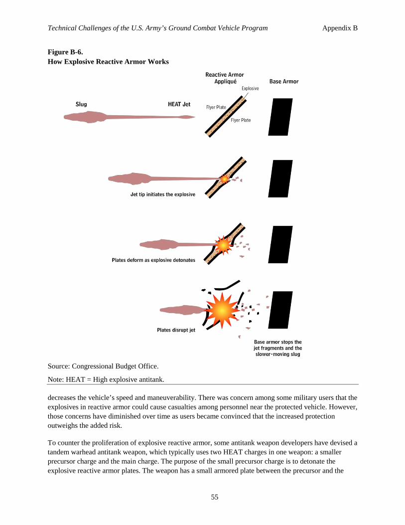
Technical Challenges of the U.S. Army’s Ground Combat Vehicle Program Appendix B
55
Figure B-6. How Explosive Reactive Armor Works
Source: Congressional Budget Office.
Note: HEAT = High explosive antitank.
decreases the vehicle’s speed and maneuverability. There was concern among some military users that the explosives in reactive armor could cause casualties among personnel near the protected vehicle. However, those concerns have diminished over time as users became convinced that the increased protection outweighs the added risk.
To counter the proliferation of explosive reactive armor, some antitank weapon developers have devised a tandem warhead antitank weapon, which typically uses two HEAT charges in one weapon: a smaller precursor charge and the main charge. The purpose of the small precursor charge is to detonate the explosive reactive armor plates. The weapon has a small armored plate between the precursor and the
Technical Challenges of the U.S. Army’s Ground Combat Vehicle Program Appendix B
56
main charge to protect the main charge from the blast of the precursor. Once the explosion of the reactive armor tiles is complete, the main HEAT charge follows—usually about 500 milliseconds later—and has a clear path to the base armor. In response, armor designers have developed clever arrangements of reactive plates to defeat tandem shaped charges.
Explosive reactive armor designed to stop HEAT warheads may not be effective against EFP warheads. As mentioned above, EFP velocities are usually insufficient to set off the explosives in reactive armor, and fast-moving reactive armor plates will not fully interact with all EFP fragments. However, there are now second-generation reactive armors that can be effective against both EFP and HEAT shaped charges. They use various combinations of more-sensitive explosives and plates of varying thickness or geometry to defeat both types of warheads. Some examples of those reactive armors include the Russian Kontact-5, Ultrax/CLARA made by Verseidag Indutex/Dynamit Nobel, and the Ukrainian NOZH (Knife).5
5 For information about the Ukrainian NOZH, see www.army-guide.com/eng/product3705.html.
Glossary
Active protection system. A defensive system that uses hard-kill countermeasures to prevent a projectile from hitting a target.
Appliqué armor. Armor that is not used in a load-bearing application (that is, it is bolted, glued, or somehow attached to a load-bearing frame).
Areal density. A metric of armor efficiency in which the weight of an armor design is divided by the surface area protected by that same design. It is usually expressed in terms of pounds per square foot.
Asymmetric tactics. Techniques and low-level operations used in a conflict where the belligerents’ resources differ in quality or quantity in order to exploit each other’s characteristic weaknesses.
Battlefield clutter. Man-made or natural features that partially or totally obscure sensors, especially radar and infrared, by creating false images and radar echoes.
Cone diameter. The diameter of a shaped-charge warhead; usually the width of the metal liner.
Dismounts. Infantry soldiers assigned to a vehicle that disembark to perform their mission. They could be thought of as passengers.
EFP. Explosively formed penetrator. A type of shaped charge that forms a lower-speed (1 to 3 kilometers per second) slug without a jet. Also called an explosively formed projectile or explosively forged penetrator.
FCS. Future Combat System. A canceled U.S. Army combat vehicle program that immediately preceded the Ground Combat Vehicle program.
GCV. Ground Combat Vehicle.
Hard kill. A countermeasure that physically interacts with a projectile to destroy it before it hits the target.
HEAT. High explosive antitank. A type of shaped charge that forms a high-speed (10 kilometers per second) metal jet designed to penetrate large amounts of armor.
HMMWVs. High Mobility Multipurpose Wheeled Vehicle. A four-wheel-drive tactical truck used for various missions, from carrying supplies to mounting weapons, in a support role.
IED. Improvised explosive device. A bomb fabricated in an improvised manner incorporating destructive, lethal, noxious, pyrotechnic, or incendiary chemicals and designed to destroy or incapacitate personnel or vehicles.
Infantry fighting vehicle. An armored combat vehicle designed to carry infantry and to support them with fire from onboard weapons.
Technical Challenges of the U.S. Army’s Ground Combat Vehicle Program Glossary
58
Jet. The high speed stream of metal produced by a HEAT shaped charge that can penetrate deeply into armor.
MRAP. Mine resistant ambush protected vehicle. A vehicle designed to protect the crew from mine and IED attacks.
Reactive armor systems. A protective layer on a target that responds in some way to the impact of a weapon in order to reduce the damage done to the target.
RHA. Rolled homogeneous armor. RHA equivalency is used to estimate either the penetrative capability of a projectile or the protective capability of a type of armor that may or may not be steel compared with an equivalent amount of rolled homogeneous steel. Because of variations in armor shape, quality, material, and case-by-case performance, the RHA equivalency is only approximate.
RPG, RPG-7. Rocket-propelled grenade. The RPG-7 is a 1970s-era Soviet design now produced in several countries and that has proliferated widely around the world.
Shaped charge. A type of warhead designed to create a projectile formed by the detonation of an explosive.
Slug. The portion of a shaped-charge projectile that is not well formed and moves more slowly than the jet tip.
Soft kill . A countermeasure that causes a projectile to miss the target or otherwise fail by means other than physically interacting with the projectile.
Spall liner. A material added to the inside of an armored vehicle structure, usually in the crew compartment, to absorb fragments from a penetrating round but not the round itself. They are usually made with fiber composites such as Kevlar or spun glass.
SWAP. Space, weight, armor, power. A term used to indicate that these parameters must be traded against each other when designing a vehicle.
Tank. A tracked, armored combat vehicle that usually has a large-caliber cannon and heavy armor.