Embed Size (px)
Citation preview

Technical Committee Reports 2012 – Digest Edition, 87-107 / Copyright © 2012 Japan Concrete Institute 87
Committee Report : JCI- TC104A
Technical Committee on Innovative Application of Fiber Reinforced
Cementitious Composites Yoshio KANEKO, Minoru KUNIEDA, Toshiyuki KANAKUBO and Yusuke KURIHASI
Abstract
Despite the ability of fiber-reinforced cementitious composites to add value to structures
by integrating elements of structural design and material design, a rational design method
where both design elements are integrated (or seamless construction) has not been fully
reviewed at present. Bearing in mind that fiber-reinforced cementitious composites can
show their superiority by introducing a long-term performance design concept, this research
committee established three working WGs, namely, (1) New Uses WG, (2) Performance
Evaluation WG, and (3) Environmental Response WG, to propose new uses of
fiber-reinforced cementitious composites.
Keywords: Fiber-reinforced cementitious composites, long-term performance design,
material-structure seamless construction, crack width
1. Introduction
Just about 40 years have passed since short steel fiber-reinforced concrete technology was
adopted in the 1970s. Short fiber-reinforced cementitious composites are, needless to say,
concrete materials with which short fibers are mixed and, their ability to withstand external
force with the support of fiber crosslinking even in the case of a cracks, can drastically
increase bending strength and toughness compared to ordinary concrete. In particular, the
merit of flexibility of selection of the kind of fiber as well as the mixing amount makes them
attractive materials that can be freely designed to meet the performance required by a
structure or its member. In other words, once seamless material-structure construction is put
into practice and if materials are developed after the performance required for concrete
structures is clearly identified, applications which exploit the merit of those materials may
possibly be discovered.
As a project of the Japan Concrete Institute, activities contributing to the promotion of
new high-toughness cementitious composites were undertaken in 2001 to 2003 by the “Task
Committee on Ductile Fiber Reinforced Cementitious Composites (DFRCC) (chaired by Prof.

88 Y. Kaneko, M. Kunieda, T. kanakubo and Y. Kurihasi / Technical Committee Reports 2012 – Digest Edition, 87-107
Keitetsu Rokugo from Gifu University)”.1)
Table 1: Committee members
This research committee was established for the purpose of providing information to help
further expand the use of fiber-reinforced cementitious composites with the changing
development and application of materials for fiber-reinforced cementitious composites in
mind, and established three WGs to conduct two-year activities. Table 1 shows the
Chair Yoshio KANEKO Kyoto University Secretary Minoru KUNIEDA Nagoya University
Secretary Toshiyuki KANAKUBO Tsukuba University
Secretary Yusuke KURIHASI Muroran Institute of Technology
Takayuki ASAI Nippon Expressway Research Institute Co., Ltd.
Takahiko AMINO Toa Corporation Seiichiro ISHIHARA Asanuma Corporation Masato ISO Fukui University Hajime ITO Toyama Prefectural University Mitsuyasu IWANAMI Port and Airport Research Institute Atsuhisa OGAWA Kuraray Co., Ltd. Takatsune KIKUTA Tohoku University
Akihiro SHIBA Sumitomo Mitsui Construction Co., Ltd.
Ryosuke SHIONAGA IHI Corporation
Haruhiko SUWADA National Institute for Land and Infrastructure Management
Shigeki SEKO Aichi Institute of Technology Kohei NAGAI The University of Tokyo Satoru NAGAI Kajima Technical Research Institute Takaaki HIRATA Obayashi Technical Research Institute Kenichi HORIGUCHI Taisei Technology Center Tokuichi MAEDA Toyobo Co., Ltd. Nobuyuki MAEDA Shimizu Corporation Yoichiro MUROGA Hagiwara Industries Inc. Ken WATANABE Railway Technical Research Institute Koji YAMANOBE Shimizu Institute of Technology Corresponding member Yuichi SATO Kyoto University
Observer Kohei ASANO Tsukuba University JCI secretary Kazuhisa INOUE Japan Concrete Institute

Y. Kaneko, M. Kunieda, T. kanakubo and Y. Kurihasi / Technical Committee Reports 2012 – Digest Edition, 87-107 89
committee members.
WG1 (New Uses WG headed by Kurihasi) has sought and proposed new uses through the
survey of papers published in the past decade.
WG2 (Crack Width Evaluation WG headed by Kanakubo), paying attention to smaller
crack widths as one of the superiorities of fiber-reinforced cementitious composites, surveyed
previous methods of crack width evaluation and, at the same time, made a proposal
concerning the ideal method of evaluating crack widths for relevant materials.
WG3 (Environmental Response WG headed by Kunieda) pointed out the necessity to
consider environmental loads of fiber-reinforced cementitious composites throughout their
entire life span, first discussed LCCO2, then proposed new uses from the viewpoint of
environmental load mitigation, and reviewed the recycling efficiency of fiber-reinforced
concrete.
A special aspect of review by all WGs was that it was based on the viewpoint of where in
the stage of improving a structure’s “long-term performance”, the fiber-reinforced
cementitious composites should show their superiority. Here, let us outline the activities of
each WG.
2. Possibilities of fiber-reinforced cementitious composites for the purpose of
improving the long-term performance of a structure (WG1)
To explore the ability of fiber-reinforced cementitous composites (FRCC) to improve the
long-term performance of a structure, the trend of previous R&D and practical applications
was surveyed, and approaches toward the development of new uses were suggested from four
viewpoints. Finally, we proposed uses where the application of FRCC is inevitable to secure
the long-term performance of concrete structures.
2.1 New uses where R&D and practical applications are under way
Here is an outline survey of papers on R&D and practical applications of fiber-reinforced
cementitious composites for the purpose of improving long-term performance of concrete
structures. The papers surveyed are those published from 2000 to 2011 including a
collection of papers on concrete civil engineering, a collection of annual papers on concrete
civil engineering, Proceedings of the Japan Concrete Institute (Concrete Journal/Concrete
Technology Reports), a collection of papers of the Japan Society of Civil Engineers, the AIJ’s
Journal of Structural and Construction Engineering,the Journal of Structural Engineering, the
ACI Materials Journal, and the ACI Structural Journal, totaling 646 papers. Applicable

90 Y. Kaneko, M. Kunieda, T. kanakubo and Y. Kurihasi / Technical Committee Reports 2012 – Digest Edition, 87-107
cases were compiled by hearings from members of this committee and concerned persons.
These papers and applicable cases were sorted with reference to the matters listed below:
1) Target structures (newly built or existing structures)
2) Materials used (kind of fiber)
3) Applicable regions
4) Research objective
5) Review method
6) Review of long-term performance
7) Existing design guidelines, evaluation method
8) Standard test method used, etc.
9) Proposed evaluation method
10) Merits
11) Future review items
12) Literature cited
For reference, these data were, after classification into architecture (materials/structure)
and civil engineering (materials/structure), included in the CD-ROM attached to this research
committee’s report.
Moreover, these research papers were classified into 10 areas including prevention of
delamination, prevention of cracks, load resistance improvement, earthquake resistance
improvement, higher fatigue durability, impact resistance improvement, higher explosion
resistance, fire resistance improvement, labor-saving construction, and long-term durability
for use in newly built structures, and into 5 areas including prevention of delamination,
cross-sectional repair, load resistance improvement, earthquake resistance improvement, and
higher fatigue durability for use in existing structures, and analyzed such as for the kind of
FRCC used in each category, applicable regions, the trend of research, and future problems to
be reviewed. Table 2 shows the number of research papers published each year by each area.
The table indicates that the most common objective in newly built structures was to
improve load resistance, which is still the subject of a large number of studies. In the
civil/structural engineering area in particular, most cases are intended to improve the shear
capacity of beam members or the punching shear strength of slab members.
The second most common objective is labor-saving. Main uses are intended to improve
the load and earthquake resistances of a member through the application of FRCC to reduce
cross-sectional area for weight-saving, or to compensate for a shear strength shortfall of
light-weight concrete RC/PC members by using FRCC so that weight-saving may be realized,

Y. Kaneko, M. Kunieda, T. kanakubo and Y. Kurihasi / Technical Committee Reports 2012 – Digest Edition, 87-107 91
Table 2: Number of papers on new uses whose R&D and practical applications are under way
Publication year ‘00 ‘01 ‘02 ‘03 ‘04 ‘05 ‘06 ‘07 ‘08 ‘09 ‘10 ‘11 TotalPrevention of delamination 2 1 1 1 5Prevention of cracks 2 1 4 5 5 4 6 8 4 2 5 3 49Load resistance improvement 3 4 1 4 9 7 16 19 14 10 18 18 123Earthquake resistance improvement 3 2 10 6 3 8 10 9 8 8 6 1 74Higher fatigue durability 2 2 1 1 1 1 2 3 13Impact resistance improvement 2 2 1 1 1 3 10Higher explosion resistance 2 1 4 7Fire resistance improvement 1 2 1 1 3 3 4 10 5 4 4 1 39Labor-saving construction 1 3 6 5 14 7 7 6 14 5 6 3 77
Newly built
Long-term durability 1 1 5 5 3 4 5 2 26Prevention of delamination 3 1 1 1 6Repairing materials 6 2 1 1 1 1 2 1 15Load resistance improvement 3 3 3 5 5 2 3 24Earthquake resistance improvement 1 2 5 3 5 2 6 3 2 29Labor-saving construction 3 1 2 3 9
Existing
Higher fatigue durability 1 1 4 6
etc. These uses, therefore, lead to labor-saving by improving a member’s load
resistance/earthquake resistance. Other uses such as in buried frameworks and various joints
were also found.
Many of the studies were also intended to improve earthquake resistance, and they tend to
be found mainly in the architectural/structural engineering area. Other than applications in
pillars, beam-column joints, and boundary beams, many cases relate to CES (Concrete
Encased Steel) compositional structures consisting only of steel frames and FRCC.
Long-term durability was also reviewed positively in terms of salt damage, freezing damage,
neutralization, dimensional stability, wear resistance, and so on. Recently, research on the
self-healing performance due to the effect of FRCC in limiting cracks is also under way.
On the other hand, the most common objective related to existing structures is to improve
earthquake resistance. Applications are found in cases of using FRCC as a damping device
in additional pillars, earthquake-resistant walls, structural bases, etc., as well as those of using

92 Y. Kaneko, M. Kunieda, T. kanakubo and Y. Kurihasi / Technical Committee Reports 2012 – Digest Edition, 87-107
CES compositional structures in additional pillars, etc. The second most common objective
is to improve load resistance, and application is found in shotcrete for repair/reinforcement
purposes, concrete with increased thickness, post-installed panels, etc.
For each area’s specific applications and other information, see committee reports.
2.2 Milestone for the development of new uses
The creation of new uses for fiber-reinforced cementitious composites (FRCC) and the
expansion of their range of application will presumably require review of their
design/construction by extending previous studies, and accumulating data and reviews of 1)
any innovative concept for FRCC and 2) the development of new materials including
improvement of existing materials.
As regards a new concept for FRCC, the committee focused on the application of a
long-term performance design concept and mitigation of environmental loads. As for
development of new materials including improvement of existing materials, it was decided to
find solutions to problems of existing FRCC and approaches to the development of new
FRCC. Table 3 shows a list of points to which attention should be paid for each approach.
They are outlined as follows:
Table 3: Milestone for the development of new uses Approach to the development of new
uses Points to which attention shall be paid
From the viewpoint of long-term performance design Long-term performance design concept
Maintenance-free, semi-permanent structure Semi-permanent structure to be repaired/reinforced Cross-sectional reduction LCCO2 evaluation
From the viewpoint of environmental load mitigation
Eco-materials Quality Economy From the viewpoint of problem solutionLaws and regulations New fiber materials New design concept materials From the viewpoint of new material
development Existing materials improvement
Y. Kaneko, M. Kunieda, T. kanakubo and Y. Kurihasi / Technical Committee Reports 2012 – Digest Edition, 87-107 93
(1) Approach from the viewpoint of long-term performance design by taking time axis into
consideration
In the area of architecture, long-term performance design is defined as a design which
allows any structure to manifest its designed usability/security- and durability-related quality
and performance during its in-service period. Also in the area of civil engineering, durability,
as required performance, must meet the performance level for various parameters during the
design durable period.
Furthermore, the adoption of a time axis in these performance designs enables structures
to be managed while taking account of the social trend of their life extension/maintenance,
based on a performance evaluation against a continual time axis (health monitoring).
Therefore, extremely rational design may become possible.
On the other hand, since it is expected that FRCC will limit crack openings after cracking
occurs, post-cracking tensile stresses give a gradually increasing characteristic or a gradually
decreasing characteristic. Thus, unlike ordinary concrete and mortar, FRCC exhibits
moderate post-peak behavior, so it is inferred that chronological change of crack widths can
be estimated with relative ease. In designing a variety of structures using FRCC, if an
estimated crack width-based long-term performance design concept is applied, then it may
possibly lead to a structural design which makes the most of the advantages of FRCC.
At present, this remains only a concept described in Reference 2), and it is necessary in
the future to review a concrete method of evaluating long-term performance. Since it is
particularly important to estimate the chronological change of crack widths, it is expected that
studies will be encouraged by the achievements of WG2 of this research committee.
(2) Approach from the viewpoint of environmental load mitigation
FRCC is characterized by its high ductility capacity since, even after cracks occur, the
fiber’s crosslinking effect limits crack openings. At the same time, however, more energy is
required when demolishing the structure than ordinary concrete, and it is also expected that
environmental loads will become heavier. On the other hand, if FRCC’s kinetic property and
durability are improved, it is also considered possible to design a semi-permanently
serviceable structure. More specifically, a method of designing a maintenance-free or
semi-permanent structure requiring repair/reinforcement is considered.
In addition, streamlining of substructure and foundation work brought about by weight
reduction of superstructures due to the application of FRCC results in saving the amount of
concrete used, as well as reduction of CO2 emissions from cement making. Besides, by
allowing FRCC to be composed of recycled materials, waste-mixed cement, etc., it may

94 Y. Kaneko, M. Kunieda, T. kanakubo and Y. Kurihasi / Technical Committee Reports 2012 – Digest Edition, 87-107
possibly mitigate environmental loads.
(3) Approach from the viewpoint of problem solution
Section 2.1 introduced new uses where R&D and practical applications are under way,
but promotion is still slow as regards practical applications. One of the main reasons for this
is the problem of qualitative instability. FRCC, in some cases, significantly fluctuates in
terms of its fiber’s dispersibility and orientation, often having a direct impact on kinetic
property. Solutions to the problems include development of a means to stabilize fiber
dispersibility/orientation, contrivance for construction, etc., but it is considered necessary as a
first step to establish technology for secondary products of concrete.
Second is the problem of economy. This type of problem is mostly caused by an
increase in initial costs due to application of FRCC. Several cases where this problem has
been successfully solved are reported, including application to shield tunnel segments3).
New uses may, therefore, be possibly found by exploring any application method that has
initial cost-effectiveness. Of course, it is also important in the future to propagate a design
concept which examines not only initial costs but also cost- effectiveness from the viewpoint
of life cycle costs (LCCs), taking advantage of the long-term performance of FRCC.
Here, as for FRCC, there are some cases where material performance is higher than
required, which is a factor for higher costs not resulting in practical use. It is, therefore,
assumed that, if a material design method corresponding to the performance required for a
structure is established, it enables mix design which limits surplus performance as much as
possible, presumably solving the problem of economy.
The problem to be taken up finally is that of laws and regulations. Particularly, in the
case of architectural structures, when a material not complying with JIS like FRCC is used, it
is necessary for each architectural structure to be separately accredited by the competent
minister. As a solution, it seems important to keep advocating the merits of FRCC through
research activities like those conducted by this committee, as well as to establish a seamless
design/construction method where not only materials and structures but also the flow of
construction is consistent.
(4) Approach from the viewpoint of new material development
Although a number of FRCCs have been developed so far, it is considered that any higher
cost-effectiveness materials will enable creation of new applications. Here, let us introduce
three points to which attention should be paid, and their present status.
First is the application of new fiber materials. Future technological innovation may
result in the development of fiber materials whose kinetic properties and durability are better

Y. Kaneko, M. Kunieda, T. kanakubo and Y. Kurihasi / Technical Committee Reports 2012 – Digest Edition, 87-107 95
than ever before. And recently, it has become clear that application of iron sawdust (called
steel chip) enable the manufacture of economical and high-performance FRCC.
Second is the development of new design concept-based materials. More specifically, it
is fiber hybridization, although there appear to be several cases where this has already been
reviewed. FRCC undergoes a substantial change in its kinetic property by changing the
property of the mixed fiber and shape/size, which enables its performance to be changed by
applying two or more kinds of fiber combined. There are, however, recent reports of the
development of ultra high-strength mortar with curing characteristics, raising expectations
that development of new design concept-based materials will be promoted in the future.
Third is the improvement of existing FRCC. For example, the range of application of
UFC has been limited to only plain concrete members or post-tensioning PC members due to
the inevitability of heat curing and sizable shrinking. However, recently, heat
curing-dispensable and shrinkage-compensation UFC has been developed. Thus, it is also
considered possible to create new uses through the improvement of existing FRCC.
In this section, we have outlined each approach. For further details of the matters
reviewed here, see committee reports.
2.3 Proposal for inevitable applications of fiber-reinforced cementitous composites
Up to the preceding section, this report has mentioned a number of merits of FRCC, and
approaches to develop uses of FRCC. On the other hand, looking at the present state of
concrete structures, their manufacture, transportation, construction, curing, and in-service
processes still retain a number of problems. Regarding problems of a great post-service
impact on third parties in particular, there are many cases where measures have already been
taken such as by applying FRCC, but there are many cases where no measures have been
taken.
Hence, in this section, let us discuss the regions where the application of FRCC is
deemed inevitable, and how it should be used.
(1) Prevention of concrete fragments from spalling
Since concrete fragment spalling accidents occurred one after another in and after 1999,
anti-spalling measures have come to be taken in numerous concrete structures. At present,
however, some local governments and structural administrators have neither taken adequate
measures nor prepared sufficient guidelines, etc., as yet.
With respect to the prevention of concrete fragments from spalling, therefore, it is
important to improve methods of handling and maintaining newly built structures.

96 Y. Kaneko, M. Kunieda, T. kanakubo and Y. Kurihasi / Technical Committee Reports 2012 – Digest Edition, 87-107
Particularly, since the application of FRCC is extremely effective in preventing concrete
fragments from spalling, we should like to propose that the application of FRCC should be
made compulsory in concrete structures very likely to cause damage to third parties like
tunnels, elevated bridges, and rock sheds,.
(2) Prevention of brittle fracture
Bridge maintenance is indispensable not only for saving LCC due to the life extension of
a bridge, but also for safe running of vehicles, etc. Recently, however, cases of cave-in from
punching shear fracture due to the fatigue of floor slabs, etc., are increasing. Looking at the
present state of architectural structures, the use of ultra high-strength concrete tends to be
promoted due to latter-day Manhattanization. However, it needs to be taken into full
consideration that ultra high-strength concrete is liable to extremely brittle fracture at the time
of compression failure.
Considering that the application of FRCC is quite effective in inhibiting such brittle
fracture, we should like to propose that the application of FRCC should be made compulsory
in areas where this kind of fracture is assumed to occur.
3. Evaluation of crack widths(WG2)
As for fiber-reinforced cementitious composites, since fibers crosslink cracks in a matrix
even after cracking and transmit stresses, crack width extension is limited to a greater extent
than in a matrix containing no fiber. In this chapter, we attempt to quantitatively evaluate
fiber-reinforced cementitious composite crack widths, and discuss relevant information as
well as information for the expansion of uses.
3.1 Long-term performance design and crack width evaluation for concrete
members
As regards a structure, not only material degradation over time but also, in the long run,
time-related deterioration in structural resistance can be expected. This report proposes a
concept of “long-term performance design”, based on the application of fiber-reinforced
cementitious materials as a new construction method which permits seamless design of the
relationship between material properties and structural performance, as shown in Fig. 12),4).
Here, in-service years were set on the horizontal axis as time axis and performance indicators
to quantify the structural performance of a structure, on the vertical axis. In the figure, the
performance indicator is defined as an indicator giving a measure to evaluate the structural
performance of a structure, the required long-term performance is defined as the long-term

Y. Kaneko, M. Kunieda, T. kanakubo and Y. Kurihasi / Technical Committee Reports 2012 – Digest Edition, 87-107 97
performance required during the in-service period, and the targeted performance is defined as
the minimum long-term performance necessary to meet the required long-term performance
during the set in-service period. It shows that, if the performance of an actual structure is
below the targeted performance, the required long-term performance cannot be obtained
during the in-service period. For an ordinary structure, repair and/or reinforcement becomes
necessary to meet the targeted performance. Fiber reinforcement will probably slow the
deterioration of structural performance, and may also reduce the extent of damage due to
short-term disturbance. As for long-term performance design with the time axis taken into
account, fiber reinforcement seems to be effective for the performance of concrete (or
cementitious) structures.
Performance indicator
Completion time In-service years Time
(Elapsed years) Fig. 1: “Long-term performance design” concept
3.2 Information relating to strain hardening-type materials
(1) Materials design technology for ECC
As for ECC (Engineered Cementitious Composite) with expectation of multiple cracks
and deformation behavior up to several-percent tensile strain under tensile stress after initial
cracking, it is said that structural behavior can be evaluated on the level of ECC-based
members by using the micro-level performance of constituent materials5). Fig. 2 shows an
outline of material design technology for ECC5). Level 1 shows the behavior of pull-out
from a single fiber matrix, by using the micromechanics parameter which shows the
micro-level performance of fiber and matrix. Level 2 shows the crosslinking law for
crosslinking cracks by multiple fibers based on the pull-out behavior of single fiber. Level 3
Performance reduction due to damage phenomenon(damage by earthquake, etc.) * Structural performance can be restored by repair/reinforcement
Performance of an actual structure
Post-repair/reinforcement performanceTargeted performance
*Several grades can be set
Required long-term performance
*Performance to be required
(Additional fiber reinforcement)
Not repaired/reinforcedPost-damage (fiber-reinforced structure)
(Fiber-reinforced structure)(Not necessary to be fixed)

98 Y. Kaneko, M. Kunieda, T. kanakubo and Y. Kurihasi / Technical Committee Reports 2012 – Digest Edition, 87-107
shows the stress-strain relationship as a macro-dynamic behavior of materials by using the
crosslinking law. Level 4 shows the reflection of the stress-strain relationship of materials
on the structural behavior of members.
This means that, if micro-level material parameters are used, even structure- and
member-level crack widths can be evaluated. There are, however, problems to be solved by
evaluation on each level, and some evaluation variables (for example, single fiber-matrix
interfacial shear stress=bond stress) which need to be experimentally determined.
↑
↓
応力
ひずみ
外力
↑引抜荷重繊維
繊維マトリクス 構造部材への反映マイクロメカニクス
パラメータ
レベル1 レベル2 レベル3 レベル4
単繊維モデル 繊維架橋モデル複数ひび割れ条件構成則モデル 構造解析モデル
(a) マイクロメカニクス パラメータ
(b) 単繊維引抜挙動 (c) 繊維によるひび 割れ架橋の挙動
(d) 巨視的材料力学挙動 (e) 部材の構造挙動
ミクロレベル マクロレベルMicro level Macro level
External force
Micromechanics parameter
Level 1 Level 4 Level 3Level 2To be reflected in
structural members
Matrix FiberPull-out load
FiberStress
Strain Single fiber model Fiber crosslinking
model
Plural cracks condition
constitutive law model
Structural analysis model
Fig. 2: Materials design technology for ECC5)
Fig. 3: Relationship between tension softening diagram and tensile stress-strain curve6)
(3) Crack width evaluation for UHP-SHCC
In recent years, UHP-SHCC (Ultra High-Performance Strain-Hardening Cementitious
Composite) having the characteristics of ultra-high strength and high toughness has been
developed, and research on it is under way7). The material demonstrates its strain hardening
(a) Micromechanics parameter
(b) Single fiber’s pull-out behavior
(c) Fiber’s behavior to crosslink cracks
(d) Macro-dynamic materials behavior
(e) Structural behavior of members
Tens
ile st
ress
Opening displacement
Tensile stress
Equivalent specific length
Strain
Tens
ile st
ress

Y. Kaneko, M. Kunieda, T. kanakubo and Y. Kurihasi / Technical Committee Reports 2012 – Digest Edition, 87-107 99
capability under working tensile stress by refining the matrix with the water cementitious
material ratio of 0.22 and through silica fume blending, and then by mixing it with
high-strength PE fiber (Fig. 4). Research is still now under way on this material’s single
fiber bond behavior8), 9), stress-strain-crack width relationshipse.g., 9),10), and member-level
evaluatione.g.,11).
Fig. 4: UHP-SHCC tensile stress-strain relationship7)
3.3 Information relating to tension softening-type materials
In the case of FRC (Fiber-Reinforced Concrete), the effect of mixing short fiber is
demonstrated as performance to retain tensile force after concrete cracking. To
quantitatively indicate this performance, a “tension softening diagram” generally plotted as a
relationship between tensile stress and crack opening displacement is used. If this property
is adopted in nonlinear FEM analysis, etc., as a material composition law of FRC itself, it
enables numerical evaluation of the deformation, proof stress, average crack width, etc., of
columns, beams, and other members in which short fibers are used.
As far as the tension softening diagram of FRC is concerned, in the case of SFRC (Steel
Fiber Reinforced Concrete), the shape, mixing ratio, and orientation of steel fiber affects its
softening characteristics. Moreover, as for nonmetallic fibers (including aramid, vinylon and
polypropyrene fibers) whose development has been promoted in recent years, softening
characteristics are systematically defined for each material by using a tension softening
diagram obtained such as from a three-point bending test (Fig. 5)12). Also from the
viewpoint of evaluating the crack width of FRC structural members, the influence of the kind

100 Y. Kaneko, M. Kunieda, T. kanakubo and Y. Kurihasi / Technical Committee Reports 2012 – Digest Edition, 87-107
of short fiber and the fiber mixing ratio on bending crack width has been reviewed for
bending crack widths of different fiber-mixed ferroconcrete beam members (Fig. 6)13).
Bin
ding
stre
ss σ
(N
/mm
2 )
Bin
ding
stre
ss σ
(N
/mm
2 )
Bin
ding
stre
ss σ
(N
/mm
2 )
Hypothetical crack width (mm) Hypothetical crack width (mm) Hypothetical crack width (mm) (a) Vinylon fiber (b) Polyethylene fiber (c) Steel fiber
Fig. 5: Different fiber-mixed concrete tension softening diagram comparison12)
Fig. 6: Evaluation of average crack width of different fiber-mixed ferroconcrete members13)
3.4 Information relating to shear property in the crack plane
The shear property of fiber-reinforced cementitious composites in the crack plane can
presumably be identified by considering not only stress transmission due to contact in the
crack plane, as systematized by research concerning shear transmission within a concrete
structure, but also the crosslinking effects of fiber. There is still no unified theory, however,
since there are diverse affectors such as the amount of aggregate and characteristics of fiber
(length, shape, adherability, rigidity, etc.). Here, let us introduce the factors to be taken into
account for the quantification of shear property in the crack plane and relevant previous
research.
π-type displacement meter Strain gauge
Bottom plan
Side View
Average strain along the axis of member (including cracks) (µ)
Reference specimen
Steel fiber
T-321 convex/concave
Aver
age
crac
kw
idth
(mm
)
Displacement meter

Y. Kaneko, M. Kunieda, T. kanakubo and Y. Kurihasi / Technical Committee Reports 2012 – Digest Edition, 87-107 101
Since fiber-reinforced cementitious composites generally contain no aggregate or contain
little coarse aggregate, their crack planes are smoother than normal concrete. Therefore, the
matrix does not seem to transmit shear much. The contribution by fibers is added in, and the
share of tension to be borne by fibers arranged at random independently from gaps as well as
the resistance of fibers due to their rigidity, need to be identified. Hence, the phenomenon is
complex if fiber characteristics are classified individually as a main factor, and then snubbing
and group effects of multiple fibers are considered. But the contribution by fibers is a factor
similar to that in the tensile model. Therefore, if a model inclusive of fiber direction pull-out
behavior is built, it can probably be applied to shear performance.
Most current research about shear transmission in the crack plane is done to identify each
material’s characteristics, and direct shearing tests are attempted in the same way as in the
case of fiber-free concretee.g.,14),15) (Fig. 7). Here, since the tensile force of randomly
arranged fibers induces a force at angles to the crack plane, it is difficult to maintain the state
of pure shear, raising the problem of secondary cracking. In recent years, a study has been
attempted by Suryanto, et al., by spatial averaging measurement and modeling of the shear
property of plural crack-type fiber-reinforced cementitious composites16) (Fig. 8). Based on
experimental tests to revolve the principal axis for loading after adoption of initial cracking
into a thin plate, the existing concrete shear transmission model is modified to identify the
shear property, implementing panel-/member-level verification.
Fig. 7: Direct shear test example14, 15)

102 Y. Kaneko, M. Kunieda, T. kanakubo and Y. Kurihasi / Technical Committee Reports 2012 – Digest Edition, 87-107
Fig. 8: Multidirectional cracking due to revolution of principal stress axis16)
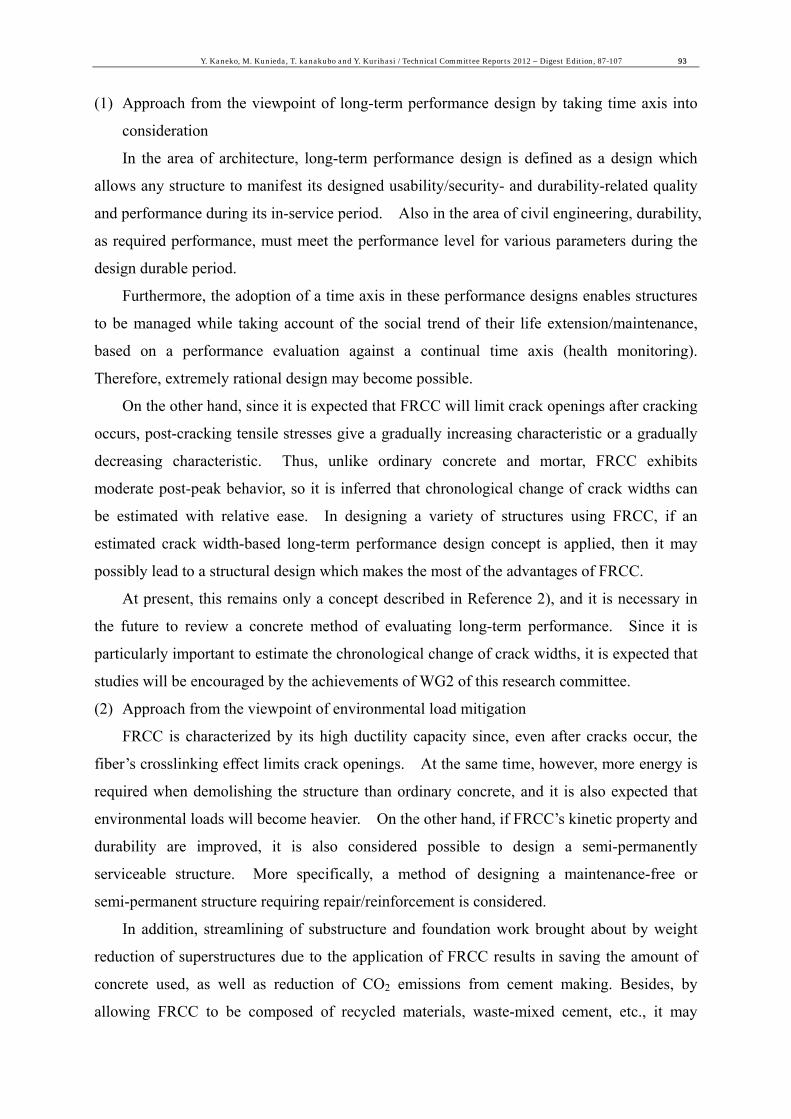
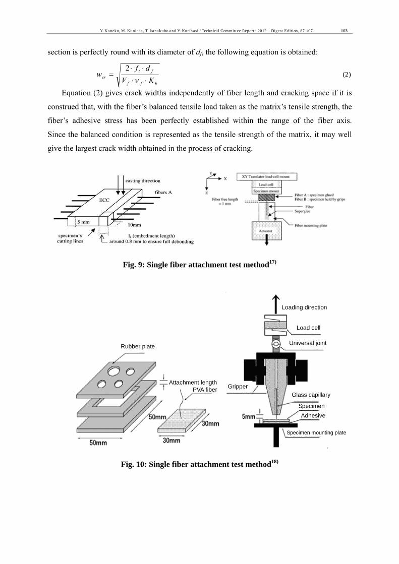
3.5 Single-fiber/matrix attachment test method
It is indispensable to adopt fiber crosslinking laws (fiber crosslinking stress-crack width
relationship) for the evaluation of crack widths in fiber-reinforced cementitious composites.
It is, however, difficult to experimentally derive a crosslinking law. The crosslinking law
depends greatly upon the interfacial properties of the single fiber embedded in the matrix, but
key factors governing interfacial properties are fiber-matrix adhesive properties and fractures
of fiber. Such factors also include a snubbing effect in which the orientation angle of the
fiber improves pull-out resistance. As an effective method of directly grasping these factors,
single fiber pull-out tests are performed to propose a variety of specimen production methods
and loading methods17),18) (Fig. 9 and Fig. 10). When conducting delicate mezzo-scale tests
like these, experimental results are also affected by specimen production and loading
methods.
3.6 Simplified method of evaluating crack widths
Consider the situation where single fibers have been embedded in the matrix and tensile
loads are occurring. If the fiber volume fraction is taken as Vf , the number of fibers per
length as Nf, and the initial gradient of a single fiber adhesive stress-pull-out volume curve as
Kb, the volume sf of fibers pulled out when new cracking occurs in the cross-section Am matrix
(under the tensile strength of ft) is determined from the following equation:
mtfbfff AfsKN ⋅=⋅⋅⋅⋅⋅ 2
21 φν (1),
where the valid coefficient of the fiber’s tensile load is vf and the fiber’s peripheral
length is Φf .
If the crack width wcr is taken as twice the amount of fiber pulled out and the fiber’s cross
Y. Kaneko, M. Kunieda, T. kanakubo and Y. Kurihasi / Technical Committee Reports 2012 – Digest Edition, 87-107 103
section is perfectly round with its diameter of df, the following equation is obtained:
bff
ftcr KV
dfw
⋅⋅
⋅⋅=
ν2
(2)
Equation (2) gives crack widths independently of fiber length and cracking space if it is
construed that, with the fiber’s balanced tensile load taken as the matrix’s tensile strength, the
fiber’s adhesive stress has been perfectly established within the range of the fiber axis.
Since the balanced condition is represented as the tensile strength of the matrix, it may well
give the largest crack width obtained in the process of cracking.
Fig. 9: Single fiber attachment test method17)
Loading direction
Load cell
Universal joint
Glass capillaryGripper
Rubber plate
Attachment lengthPVA fiber
Specimen
Specimen mounting plate
Adhesive
Fig. 10: Single fiber attachment test method18)

104 Y. Kaneko, M. Kunieda, T. kanakubo and Y. Kurihasi / Technical Committee Reports 2012 – Digest Edition, 87-107
4. Desirable fiber-reinforced cementitious composites for environmental needs (WG3)
4.1 Overview
Chapters 2 and 3 introduced case study-based reviews and crack width evaluation
methods in order to realize a long-term performance design of structures using
fiber-reinforced cementtious composites. In a model, the effects of fiber mixing are
expected to contribute to the extension of a structure’s life. At present, on the other hand,
the extension of a structure’s life cannot be discussed without consideration of recent
environmental problems.
As for the concrete structure-targeted environmental impact evaluation by JCI, the
“Technical Committee on Minimization of Global Warming Substrances and Wastes in
Concrete Sector” and the “Sustainability Committee” are now engaged in a variety of tests
and the accumulation of data. On the other hand, an evaluation of fiber-reinforced concrete
from the environmental aspect has yet to be made. And if the environmental load of
fiber-reinforced cementitious composites (with some 1% fiber) is compared with that of
ordinary concrete, that of fiber-reinforced cementitious composites is expected to be
particularly larger at the time of material procurement as well as that of abandonment.
For the purpose of providing basic information to review uses similarly to those of
normal concrete (e.g., road base material, recycled aggregate), assuming the situation where a
structure using fiber-reinforced cementitious composites is demolished, the fractural
characteristic of strain softening-type fiber-reinforced concrete (FRC) was identified.
In addition, FRCs each using either steel or polypropyrene fiber were prepared, and the
influence of short fibers on the fractural characteristic of FRC was reviewed by comparing
with that of normal concrete through sieve analysis/water absorption testing.
4.2 Recycling efficiency of fiber-reinforced concrete
(1) Materials used
The concrete used in this experiment was roughly divided into normal concrete (NC) and
5 FRC which were different as to type of fiber and mixing ratio. Normal concrete was
ready-mixed concrete (W/C=42%), and FRC was normal concrete with added polypropyrene
(PP) fiber- or steel fiber (SF). Steel fiber was 30mm-long two end-hooked fiber of the
focusing type. PP fiber was 48mm long indented straight type. The compressive strength
of concrete was 56MPa in the case of normal concrete, and ranged from 44 to 50MPa for
fiber-reinforced concrete.
This experiment used 20 cylindrical test pieces of φ150×300-mm for each kind of

Y. Kaneko, M. Kunieda, T. kanakubo and Y. Kurihasi / Technical Committee Reports 2012 – Digest Edition, 87-107 105
concrete. The test pieces prepared were fractured when they became 28 days old. They
were fractured only once, using a commercially available self-propelled jaw crusher (38-ton/h
throughput, 55-mm outlet opening).
(2) Sieve analysis test results
Fig. 11 shows the grading curve of each concrete obtained from the sieve analysis test.
In the case of PP fiber-mixed FRC, it is found that the more fibers are mixed in, the more
concrete fragments pass each sieve. This indicates that the post-fracture size of concrete
fragments is relatively small. In case of 0.2% fiber mixing, no definite difference from
normal concrete (NC) was found. It is inferred that the reason why the size of concrete
fragments discharged was smaller for FRC is that the fibers crosslinked cracks at the time of
fracture, inducing local destruction such as destruction of mortar attached around original
aggregate, but further observations are required. Also with respect to the kind of fiber,
SF-mixed FRC exhibits a little less grading in the grain size distribution than that in which
1.0% of PP, at the same fiber mixing rate, was mixed, but the overall trend is similar.
1 5 10 500
20
40
60
80
100
通過重量百分率
( %
)
NC PP 0.2 % PP 0.5 % PP 1.0 % SF 1.0 %
Sieve opening (mm)
Fig. 11: Grading curve
Photo 1 shows the appearance of concrete fragments that stayed on top of the sieve with
a nominal diameter of 10mm in the sieve analysis of each FRC test piece. More concrete
fragments than those that stayed on top of 40-mm or 20-mm sieves were found to have no
fiber attachment. This implies that, as for the concrete used in this research, most short
fibers can be removed by fracturing it into fragments that stay on top of a 10-mm sieve.
Perc
enta
ge o
f pas
sing
(%)

106 Y. Kaneko, M. Kunieda, T. kanakubo and Y. Kurihasi / Technical Committee Reports 2012 – Digest Edition, 87-107
(a) Concrete fragments in which 0.2% PP
fiber is mixed (b) Concrete fragments in which 0.5% PP
fiber is mixed
(c) Concrete fragments in which 1.0% PP
fiber is mixed (d) Concrete fragments in which 1.0% SF
is mixed Photo 1: Concrete fragments stay on top of 10mm sieve
5. Conclusion
The research committee, aiming to discover new uses of fiber-reinforced cementitious
composites, not only reviewed previous technologies, particularly those of the past decade or
so, but also crack width evaluation methods and the mitigation of environmental loads.
Model-based evaluation and utilization of short fiber effects are expected to permit wider and
wider applications in future. It is our pleasure if this review helps you in your search for
uses.
References
1) Japan Concrete Institute:Research committee report on Ductile Fiber Reinforced Cementitious Composites,2004 (in Japanese)
2) Y. Kaneko, N. Maeda and K. Yamanobe:Future vision on long-term-performance based design for architectural structures,Concrete Journal,Vol. 49, No. 5, pp.25-28, 2011 (in Japanese)
3) T. Mioke, K. Horiguchi, N. Fukuura, T. Maruya and Y. Hattori:Design method of reinforced concrete segment of shielded tunnel using steel fiber and hybrid fiber,Concrete Journal,Vol.48, No.10,pp.18-26,2010 (in Japanese)
4) Y. Kaneko, N. Maeda and K. Yamanobe:Future vision on long-term-performance based design for architectural structures,2009 AIJ annual meeting (Tohoku), PD material,pp.39-43,2009 (in Japanese)

Y. Kaneko, M. Kunieda, T. kanakubo and Y. Kurihasi / Technical Committee Reports 2012 – Digest Edition, 87-107 107
5) T. Kanda:Material design technology for high performance fiber reinforced cementitious composites,Concrete Journal,Vol.38, No.6, pp.9-16,2000 (in Japanese)
6) Japan Society of Civil Engineers:Recommendations for design and construction of ultra high strength fiber reinforced concrete structures (draft),Concrete Library 113,2004 (in Japanese)
7) A. Kamal, M. Kunieda, N. Ueda, H. Nakamura: Assessment of crack elongation performance in RC beams repaired by UHP-SHCC, Proceedings of 9th International Summer Symposium, JSCE, Yokohama University, Japan, pp 5-8, September 2007
8) K. Kozawa,M. Kunieda,T. Kanda and H. Nakamura:Bond properties of organic fiber embedded in ultra high strength matrix,Proc. of the Japan Concrete Institute,Vol.30,No.1,pp.231-236,2008 (in Japanese)
9) H. Ogura,M. Kunieda,N. Ueda and H. Nakamura:Evaluation of mechanical property on fiber reinforced cement composites by meso-scale analysis,Proc. of the Japan Concrete Institute,Vol.29,No.1,pp.309-314,2007 (in Japanese)
10) M. Kawai, T. Inaguma, Y. Uchida and K. Rokugo: Back analysis on S-S curve of multiple-fine-crack type fiber reinforced cementitiou composites,Proc. of the Japan Concrete Institute,Vol.28,No.1,pp.305-310,2006 (in Japanese)
11) T. Eguchi,M. Kunieda,H. Nagashima and H. Nakamura:Property of UHP-SHCC under asphalt pavement,Proc. of the Japan Concrete Institute,Vol.33,No.1,pp.281-286,2011 (in Japanese)
12) J. Choi, K. Yamaguchi,S. Hino and H. Kajihara:Characteristics of tension softening of super light weight concrete reinforced by short fiber,Proc. of the Japan Concrete Institute,Vol.33,No.2,pp.1243-1248,2011 (in Japanese)
13) Y. Suzuki, T. Shimomura and Y. Tanaka:Flexural crack width of RC beam with fiber reinforcement,Proc. of the Japan Concrete Institute,Vol.28,No.2,pp.1369-1374,2006 (in Japanese)
14) B. Barragan, R. Gettu, L. Agullo, and R. Zerbino: Shear Failure of Steel Fiber-Reinforced Concrete Based on Push-Off Tests, ACI Material Journal, Vol. 103, No. 4, pp.251-257, 2006
15) K. Shimizu,T. Kanakubo,T. Kanda,S. Nagai:Evaluation of shear strength for PVA-ECC member and shear transfer mechanism on crack surface,Journal of Structural and Construction Engineering, AIJ,Vol.619, pp.133-139, Sep., 2007 (in Japanese)
16) B. Suryanto, K. Nagai, K. Maekawa: Modeling and Analysis of Shear-critical ECC Members with Anisotropic Stress and Strain Fields, Journal of Advanced Concrete Technology, Vol.8, No.2, pp.239-258, 2010
17) C. Redon, V. C. Li, C. Wu, H. Hoshiro, T. Saito, and A. Ogawa : Measuring and Modifying Interface Properties of PVA fibers in ECC matrix, Journal of Materials in Civil Engineering, pp.399-406, November 2001
18) K. Asano and T. Kanakubo:Bond property of short fiber in High Performance Fiber Reinforced Cementitious Composites,proc. of AIJ annual meeting (Tokai),2012 (to be published) (in Japanese)