Embed Size (px)
Citation preview
Technical Data Index
Description Page Product Information 2-3 Specifications 4 Temperature Limits 4 Lubrication Grease 5 Dry Film 6 PTFE Liner 7 Bearing Misalignment 8 Suggested Housing Bores 9-11 Suggested Shaft Sizes 12-13 Bearing Installation 14-15 Groove Type Chart 16

Technical Data
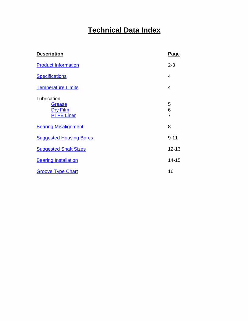
Product Information Rod Ends Aurora Bearing Company rod ends are manufactured utilizing two construction styles. They are of the two or three-piece type. Both types feature the advantages of metal-to-metal contact between bearing components (PTFE to metal interface may also be incorporated when specified). The standard two-piece style consists of a body and precision ground alloy steel ball. This type of construction allows the rod end body to carry a greater ultimate radial static load capacity compared to the equivalent three-piece construction size. This unit also offers greater misalignment capabilities. A variety of material and plating options for the component parts in this series are available. Any cold-formable steel in stainless and alloy steel categories can be specified for the body, and all hardenable alloys such as 440C stainless steel may be employed as options for the ball component.
The three-piece style consists of a body, ball, and race. This type of unit, offering fully swaged bearing construction, features the advantages of maximum spherical conformity between the ball and race. It also offers flexibility in that many different types of materials can be interchanged in each component part, providing combinations that can be tailored to meet just about any application requirement. Consult our engineering department for materials to fit your special application. Materials used in the standard catalog items are outlined on the appropriate detail page of the catalog.
Spherical Bearings These bearings incorporate the single piece race type construction, also providing excellent ball to race conformity. They can be re-lubricated through an annular groove in the outer race with two interconnecting holes positioned at 180°. Various metals may also be substituted in these types of units to meet special requirements.
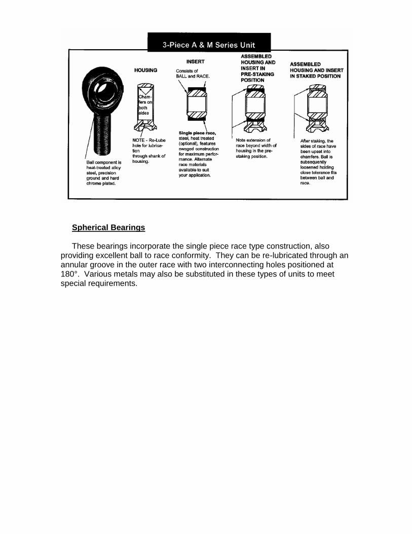
Specifications Bearings manufactured at Aurora Bearing Company are in accordance with the highest standards attained within the bearing industry. Processing and materials are certifiable to military and Federal specifications or, when required, processed to customer standards. Following are some of the specifications that we process to: Heat treat AMS-H-6875 & AMS 2759 Chrome plate AMS 2460 Zinc plate ASTM B 633 Cadmium plate AMS-QQ-P-416 Magnetic Particle Inspect ASTM E 1444/E 1444M Passivate AMS 2700 Part marking/packaging MIL-STD-130 *The above specifications are subject to change at any time due to revision, cancellation, or replacement.
Temperature Limits The following is a listing of what ultimate temperatures Aurora Bearing Company standard catalog series are capable of operating in. With the exception of the PTFE lined series, all bearings must be well lubricated with a suitable grease to meet the stated temperature.
250°F 300°F 325°F 400°F 500°F 600°F MM-T GE HXAM-T CM KM-M AM SM-E MW-T GE…ES HAB-T CW KW-M AW SW-E AM-T GEZ…ES PRM-T VCM COM-M AM-M COM-E AW-T PRXM-T VCW COM AW-M NC CM-ET PNB-T/-TG MM HCOM COM-KH WC CW-ET PWB-T/-TG MW MIB HCOM-KH MM-MT ASM(K)-T KM LCOM AIB MW-MT ASW(K)-T KW XM SIB AIB-T ANC-T/-TG SM ASM(K) XAM COM-T AWC-T/-TG SW ASW(K) RAM MIB-T AJB CM-S GMM RXAM SIB-T ASM(K)-ET CW-S GMW KM-T ASW(K)-ET CM-M CAM KW-T ATM(K)-ET CW-M VCAM HCOM-T ATM(K)-T MM-M VCAW COM-ET ATW(K)-ET MW-M GE…ES-2RS ATW(K)-T GEZ…ES-2RS GE…ET-2RS GEZ…ET-2RS ALM-T XALM-T RAM-T RXAM-T
SM-T SW-T SM-ET SW-ET

Lubrication
Grease
Grease is an oil that has synthetic filler, thickener, metallic soap, or a combination of the three added to prevent oil migration from the lubrication site. The operative properties of grease depend mostly on the base oil.
Metal on metal spherical bearings are supplied with lubrication grooves and holes to provide the ability for lubrication. Metal on metal rod ends can be furnished with grease fittings along with the lubrication grooves and holes to allow for lubrication. These bearings could gall without frequent lubrication and a reversing load to keep the grease from being pushed out. In applications with one direction loading, the grease will tend to be squeezed out of the bearing area. These types of applications should be evaluated for the use of dry film or PTFE. Following are the most common greases used by Aurora Bearing Company.
Type Specification Composition Temperature
Range
Mobilux Ep2 N/A Lithium Hydroxystearate
based grease -66°F to 266°F
Aeroshell 7
MIL-PRF-23827
Synthetic base oil w/ non-melting inorganic
thickener -100°F to 300°F
Aeroshell 17 MIL-G-21164 Synthetic base oil w/ non-
melting inorganic thickener
-100°F to 300°F
Aeroshell 33
MIL-PRF-23827; Boeing
Specification BMS 3-33
Synthetic base oil w/ lithium complex thickener
-100°F to 250°F
Aeroshell
33MS MIL-G-21164
Synthetic base oil w/ lithium complex thickener & fortified w/ Molybdenum
Disulphide
-100°F to 250°F
Mobilux is a registered trademark of the ExxonMobil Company.
Aeroshell is a registered trademark of Shell Corporation Note: The above-mentioned lubricants are current at the time of publication and are subject to change at any time without notice.

Dry Film Lubricants
Dry film lubricants offer high quality lubricating solids blended with specially formulated inorganic or organic resin binder systems, resulting in films, which can be applied to most surfaces as self-lubricating, dry coatings. These coatings contain a variety of solid lubricants, including molybdenum disulfide, graphite, and PTFE. They are utilized where extreme pressure, temperature, or environments such as radiation, vacuum, dust, or dirt, and corrosive operating conditions, limit the use of conventional lubricants. Aurora Bearing Company can provide most of our standard catalog rod ends and spherical bearings with dry film lubricants. Consult our sales representatives for details. Following are the most common dry film lubricants used by Aurora Bearing Company.
Type Specification Lubricant Binder Temperature
Range
Everlube ® 620 MIL-L-25504,
BMS3-8 MoS2
High Molecular-Weight Phenolic
-100°F to 400°F
Everlube ® 620C AS 5272 Type I MoS2 High Molecular-Weight Phenolic
-100°F to 300°F
Everlube ® 811 MIL-PRF-81329, BMS3-3 Type 2
MoS2, Graphite Silicate -365°F to 750°F
Everlube ® 812 N/A Molybdenum
Disulfide Silicate -420°F to 750°F
Everlube ® 9001 BMS3-8 MoS2, Graphite High Molecular-Weight Epoxy
-100°F to 400°F
Everlube ® 9002 MIL-PRF-46010 MoS2 High Molecular-Weight Epoxy
-100°F to 400°F
Lube-lok ® 2396 MIL-PRF-81329 MoS2, Graphite Silicate -300°F to 750°F
Lube-lok ® 4396 N/A MoS2, Graphite High Molecular-Weight Phenolic
-300°F to 450°F
Lube-lok & Everlube are registered trademarks of E/M Corporation.
Note: The above-mentioned lubricants are current at the time of publication and are subject to change at any time without notice.

PTFE Liners
PTFE (bonded coated PTFE liner) lined races are available in all three-piece bearing units and all spherical bearings. The steel race has a self-lubricating liner; a PTFE impregnated woven fabric, chemically bonded to the inner diameter of the race. Aurora Bearing Company’s PTFE liners are maintenance free and offer improved frictional characteristics. Following are the liners that Aurora Bearing Company offers.
Liner Designation
AT 1400 AT 2100 AT 2300 AT 3200
Construction PTFE/Dacron Laminate
PTFE/Fiberglass Weave
PTFE/Dacron Weave
PTFE/Nomex Laminate
Thickness (in.)
.012-.014 .010-.012 .013-.015 .014-.016
Temperature (°F)
-65° to 250° -65° to 250° -65° to 250° -65° to 325°
Static Limit Load
80,000 PSI 60,000 PSI 75,000 PSI 80,000 PSI
Stiffness Medium to High Medium Low Medium to High
Typical Performance
40,000 PSI @ ±25° & 10-20 cpm
.0045 wear max. @ 25,000 cycles
25,000 PSI @ ±25° & 10-20 cpm
.0060 wear max. @ 5,000 cycles
Contact Aurora Bearing Company
Engineering Department
40,000 PSI @ ±25° & 10-20 cpm
.0045 wear max. @ 100,000 cycles
Dynamic Capabilities
Light to medium, unidirectional or
alternating loads. Low speed
intermittent to continuous
misalignment, intermittent to
continuous oscillation.
Light unidirectional loads. Low speed,
intermittent to continuous
misalignment, intermittent to
continuous oscillation
Light to medium, alternating or
reversing loads. Medium to high
speed, intermittent to continuous
misalignment, intermittent to
continuous oscillation.
Light to heavy, unidirectional or
alternating loads. Low speed,
intermittent to continuous
misalignment, intermittent to
continuous oscillation.
Comments Good multi-purpose system
Excellent stick-slip properties, usually recommended for
high splash or underwater applications
Excellent stick-slip properties, good
vibratory conditions
Highest performance characteristics for all
applications, Qualified to SAE-AS81820 Type A

Bearing Misalignment A rod end or spherical bearing’s ability to misalign is measured by the degree of angle the ball can accommodate without interference. The angle of misalignment in a rod end is limited by the ball width and head diameter as shown in figure 1. This arrangement is called a clevis mount, and is the type represented in the standard rod end detail pages of the catalog. If added misalignment is necessary, this can be accomplished by utilizing spacers between the clevis mounting and ball face, or by using special rod ends designed to meet specific requirements. Misalignment angle in a spherical bearing is limited by the ball and race width with respect to the ball diameter, illustrated in figure 3. This is the mounting type for spherical bearings represented in the standard detail pages of the catalog. Mounting arrangements for spherical bearings such as shown in figures 2 through 4 are also used with rod ends. The misalignment angle is then calculated by selecting the proper formula.

Suggested Housing Bores


Suggested Shaft Sizes (inch)
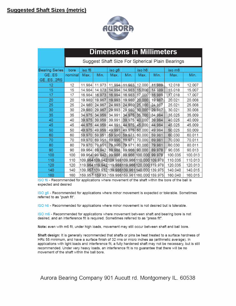
Suggested Shaft Sizes (metric)
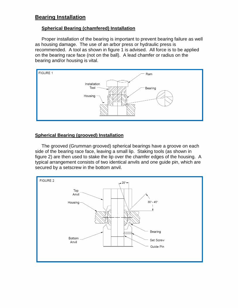
Bearing Installation Spherical Bearing (chamfered) Installation Proper installation of the bearing is important to prevent bearing failure as well as housing damage. The use of an arbor press or hydraulic press is recommended. A tool as shown in figure 1 is advised. All force is to be applied on the bearing race face (not on the ball). A lead chamfer or radius on the bearing and/or housing is vital.
Spherical Bearing (grooved) Installation The grooved (Grumman grooved) spherical bearings have a groove on each side of the bearing race face, leaving a small lip. Staking tools (as shown in figure 2) are then used to stake the lip over the chamfer edges of the housing. A typical arrangement consists of two identical anvils and one guide pin, which are secured by a setscrew in the bottom anvil.
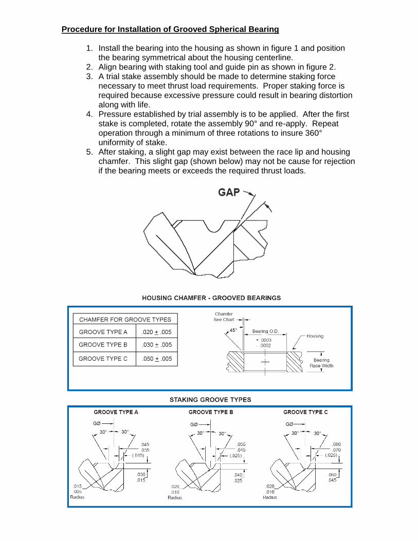
Procedure for Installation of Grooved Spherical Bearing
1. Install the bearing into the housing as shown in figure 1 and position the bearing symmetrical about the housing centerline.
2. Align bearing with staking tool and guide pin as shown in figure 2. 3. A trial stake assembly should be made to determine staking force
necessary to meet thrust load requirements. Proper staking force is required because excessive pressure could result in bearing distortion along with life.
4. Pressure established by trial assembly is to be applied. After the first stake is completed, rotate the assembly 90° and re-apply. Repeat operation through a minimum of three rotations to insure 360° uniformity of stake.
5. After staking, a slight gap may exist between the race lip and housing chamfer. This slight gap (shown below) may not be cause for rejection if the bearing meets or exceeds the required thrust loads.

Groove Type Chart Groove A Groove B Groove C ANC-3TG ANC-5TG ANC-8TG ANC-4TG ANC-5TGA ANC-9TG AWC-3TG ANC-6TG ANC-10TG AWC-4TG ANC-7TG ANC-12TG AWC-5TG AWC-6TG ANC-14TG HAB-3TG AWC-7TG ANC-16TG HAB-4TG AWC-7TGA AWC-12TG HAB-5TG AWC-8TG AWC-14TG HAB-5TG-3 AWC-9TG AWC-16TG HAB-6TG AWC-10TG PNB-8TG HAB-7TG HAB-10TG PNB-9TG HAB-8TG HAB-12TG PNB-10TG PNB-3TG HAB-14TG PNB-12TG PNB-4TG PNB-5TG PWB-12TG PWB-3TG PNB-6TG PWB-4TG PNB-7TG PWB-5TG PWB-6TG PWB-7TG PWB-8TG
PWB-9TG PWB-10TG


![GREASE APPLICATIONS ppt [Kompatibilitätsmodus]schaefferoil.de/sheets/praesentationen/greasebergbau_en.pdf · LITHIUM SOAP BASE GREASES Low to relatively high thickener content 7-12%](https://img.pdfslide.net/doc/110x75/5acda1777f8b9a93268dd504/grease-applications-ppt-kompatibilittsmodus-soap-base-greases-low-to-relatively.jpg)