Embed Size (px)
Citation preview
Critical Power
Technical Data Sheet Uninterruptible Power Supply
GE Consumer & Industrial SA
General Electric Company CH – 6595 Riazzino (Locarno) Switzerland T +41 (0)91 / 850 51 51 F +41 (0)91 / 850 52 52
www.gecriticalpower.com
imagination at work
SG
SE
_0
60
-12
0_
S1
_U
PS
_G
E_
01
SG Series 60 & 80 PurePulse
SG Series 100 &120 PurePulse
TM
TM
Critical Power
Modifications reserved Page 2/6
GE_UPS_TDS_SGS_PCE_60K_M12_1GB_V050.docx Technical Data Sheet SG Series 60 & 120 PurePulse™ CE S1
Model: SG Series 60 – 80 – 100 – 120 kVA PurePulse™ / Series 1
Issued by: Product Document Department – Riazzino - CH
Approved by: R & D Department – Riazzino - CH
Date of issue: 27.06.2016
File name: GE_UPS_TDS_SGS_ PCE_60K_M12_1GB_V050
Revision: 5.0
Identification No.:
Up-dating
Revision Concern Date
2.0 ECN 1257 (Short-circuit characteristic) + 50Ah battery cabinet 15.12.2008
3.0 ECN 1328 06.07.2009
4.0 ECN 1825 (Start-Up key & Update template) 20.04.2013
5.0 ECN 1945 (EAC conformity) + ECN 2135 (Battery maintenance) ECN 2316 (Input current THD) + Load Off/EPO procedures
14.03.2016
COPYRIGHT © 2016 by GE Consumer & Industrial SA All rights reserved.
The information contained in this publication is intended solely for the purposes indicated.
The present publication and any other documentation supplied with the UPS system is not to be reproduced, either in part or in its entirety, without the prior written consent of GE.
The illustrations and plans describing the equipment are intended as general reference only and are not necessarily complete in every detail.
The content of this publication may be subject to modification without prior notice.
Critical Power
Modifications reserved Page 3/6
GE_UPS_TDS_SGS_PCE_60K_M12_1GB_V050.docx Technical Data Sheet SG Series 60 & 120 PurePulse™ CE S1
GENERAL DATA
Topology VFI, double conversion with integrated transformer
Nominal output apparent power from PF=0.6 lag. to 0.9 lag. and at 0.9 leading KVA 60 80 100 120
Nominal output power from PF=0.9 lag. to 0.9 leading kW 54 72 90 108
Overall efficiency at 100% load PF=0.9 lag. in VFI mode
%
91.4 91.2 91.7 91.2
Overall efficiency at 75% load PF=0.9 lag. in VFI mode +/-0.2% 91.8 91.5 92.0 91.8
Overall efficiency at 50% load PF=0.9 lag. in VFI mode 91.9 91.7 91.9 92.1
Overall efficiency at 100% load in SEM mode +/-0.2% % 97.9 97.9 97.8 97.9
Heat dissipation at 100% load in VFI mode, PF=0.8 lag. & charged battery kW 4.52 6.18 7.24 9.26
Cooling air (25°C ÷ 30°C) m3/h 1320 1805 2115 2710
Audible noise level dB(A) 63 63 63 63
Battery type Valve regulated lead-acid (VRLA), vented lead-acid, NiCd
Operating temperature range UPS: 0°C ÷ 40°C
Storage temperature range -25°C ÷ +55°C
Relative Humidity Max. 95% (non-condensing)
Max. altitude without power derating Power derating (according to EN/IEC 62040-3)
1000m 1500m: -5% / 2000m: -9% / 2500m: -14% / 3000m: -18%
Protection degree IP 20 (IEC 60529)
Standards EN/IEC 62040, CE marking
EMC EN/IEC 62040-2 (Category C2 as option), Burst & Surges 2kV L-L, 4kV L-PE
Electrostatic discharge immunity 8kV contact / 15kV air discharge
Internal protection All live parts shrouded
Transport Cabinet suitable for handling by forklift
Colour RAL 9003 (white), bottom air grids RAL 7021 (black)
Installation Can be positioned against a wall and floor fixed
Service access Front and top access only
External cable connections Bottom at front of the cabinet (top as option)
Cooling Enforced ventilation with fan speed regulation
Paralleling (RPA version) Up to 6 units parallelable for redundancy or capacity in RPA configuration (optional).
RECTIFIER
Rectifier bridge Three phase, IGBT rectifier, PurePulse™ technology, overtemperature protection
Standard input voltage Nominal: 3 x 380V / 400V / 415V + N Rectifier accepted ph-ph voltage range: 340V ÷ 460V
Other input voltages On request
Input frequency 50/60 Hz +/-10% (45 ÷ 66 Hz)
Power factor 0.99
Input current THD 3% at 100% load <3% at 75% load <3.5% at 50% load
Inrush current Limited by soft-start circuit
Power walk-in 15 seconds
Output voltage tolerance +/- 1%
DC voltage ripple <1%
DC current ripple Max. 5% the battery capacity [Ah], expressed in A
Battery charging characteristic IU (DIN 41773), T° compensated floating voltage
Battery charging current limit Programmable
Input power data kVA 60 80 100 120
Input power at inverter nominal load and charged battery at PF=0.8 lag.
kW 52.5 70.0 87.3 105.3
at PF=0.9 lag. 59.1 78.8 98.2 118.5
Max. input power at inverter nominal load and max. battery recharge current (programmable)
kW 66.0 87.8 109.5 131.6
Max. battery charging current (programmable) at the beginning of battery recharge at nominal load
at PF=0.8 lag. A
33 44 55 65 at PF=0.9 lag. 17 22 27 32
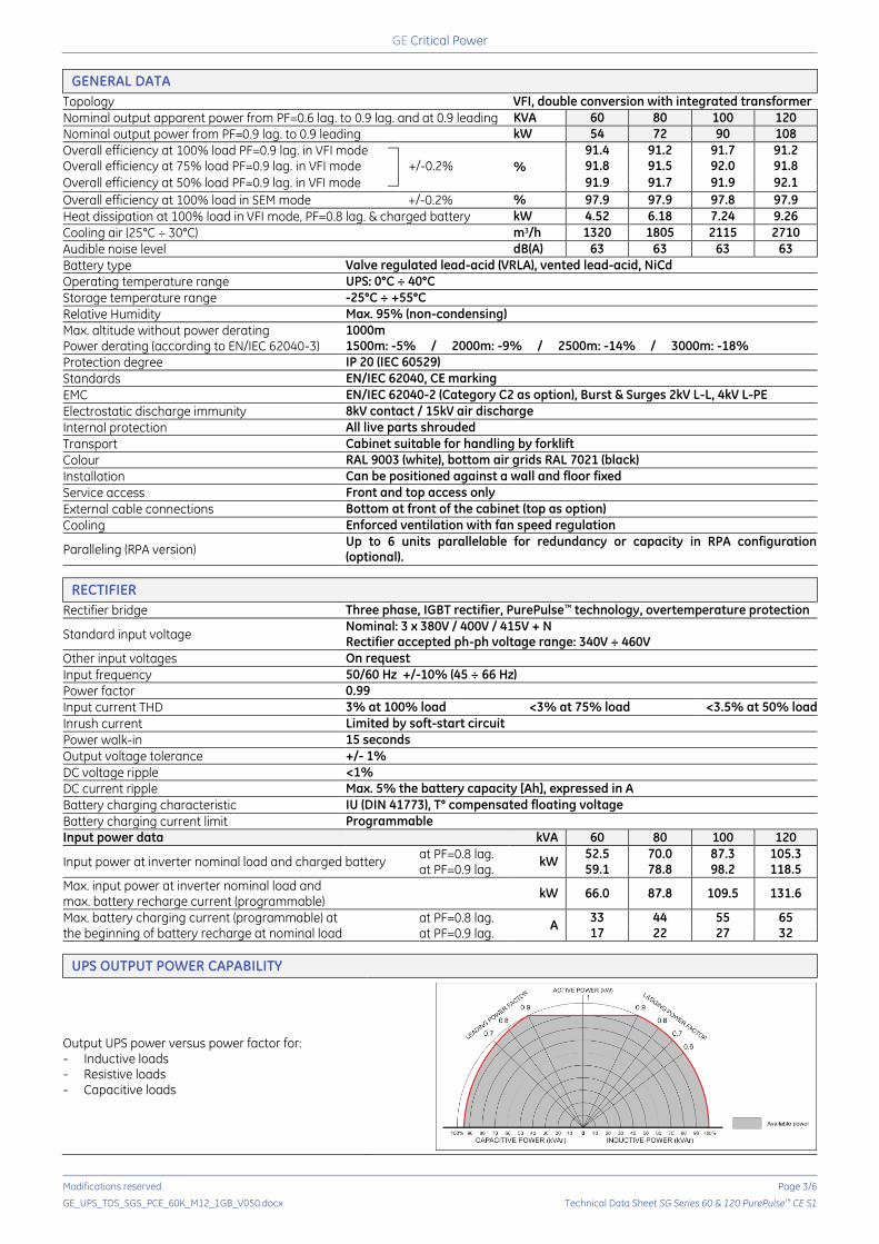
UPS OUTPUT POWER CAPABILITY
Output UPS power versus power factor for: Inductive loads Resistive loads Capacitive loads
Critical Power
Modifications reserved Page 4/6
GE_UPS_TDS_SGS_PCE_60K_M12_1GB_V050.docx Technical Data Sheet SG Series 60 & 120 PurePulse™ CE S1
BATTERY
Battery type Valve regulated lead-acid (VRLA)-standard, Vented lead-acid, wet battery and NiCd
Float voltage at 20°C 400V ÷ 436V (dependent on the number of cells)
Number of cells
VRLA at 2.27V/cell: 177÷192 cells Vented lead acid at 2.23V/cell, no boostcharge: 180÷195 cells Vented lead acid at 2.23V/cell, with boostcharge at 2.35 V/cell: 180÷185 cells NiCd at 1.41V/cell, no boostcharge: 284÷309 cells NiCd at 1.41V/cell, with boostcharge at 1.55 V/cell: 281 cells
Min. discharge voltage (programmable) Up to 310V (dependent on the number of cells)
Recharge time <5 hours up to 90% of battery capacity
“Battery to earth” fault detection Standard
Automatic and manual battery test Standard
Automatic battery contactor Standard
Battery power data kVA 60 80 100 120
DC power at full load and PF=0.8 lag. kW 50.8 67.8 84.7 101.6
DC power at full load and PF=0.9 lag. kW 57.2 76.2 95.3 114.3
DC power at full typical computer load (PF=0.66 lag.) kW 41.9 55.9 69.9 83.8
Matching battery cabinets See optional features on page 5
INVERTER
Nominal output power at PF=0.6 ... 0.9 lag. 60 – 80 – 100 - 120 kVA
Nominal output voltage (on site programmable) 3 x 380V / 400V / 415V + N
Inverter bridge SVM (Space Vector Modulation) and IGBT technology
Output transformer (for galvanic separation) Standard
Output waveform Sine wave
Output voltage tolerance: - static ..................................................................................................... +/- 1% - dynamic (at load step 0 – 100 – 0%) ...................................... +/- 3% - dynamic (at load step 0 – 50 – 0%) ......................................... +/- 2% - recovery time to +/-1% ................................................................ 5 ms - output voltage THD for 100% linear load ............................ Max. 1.5% - output voltage THD for 100% non-linear load (EN 62040) Max. 3%
Output voltage tolerance at 100% unbalanced load (Ph-N) +/- 3%
Output frequency 50/60 Hz (selectable)
Output frequency tolerance: - free-running ...................................................................................... +/- 0.1% - with mains synchronisation adjustable to .......................... +/- 4%
Phase displacement: - at 100% balanced load ................................................................ 120°: +/- 1% - at 100% unbalanced load ........................................................... 120°: +/- 3%
Overload capability (at 25°C ambient temperature) 125% - 10 minutes, 150% - 1 minute
Short-circuit characteristic Electronic short-circuit protection, current limit to: 2.7 times In for 200 ms between phase and phase 4.0 times In for 200 ms between phase and N/PE
MCCB clearance capability (selectivity) 20% In within 5-10ms (with MCCB class C or magn. trip at max. 10In)
Crest factor >3:1
BYPASS
Input connection Separate (dual input-recommended) or common to the rectifier input
Primary components
- Static switch (SCR) on bypass - Electromechanic contactors (backfeed protection) on bypass and
inverter - 2 manual switches for maintenance bypass
Voltage limits for inverter/bypass load transfers +/- 10% (adjustable)
Overload on bypass 200% for 5 minutes & 45 times In for 10 ms, non repetitive
INTERFACING
6 programmable signalling voltage-free contacts (available on Delta and block terminals)
- Standard information for easy integration and signalling - 27 user settable signals
Serial channel RS232 (on Delta 9 pin connector) Standard
Input signals - EMERGENCY POWER OFF (n/c contact, customer supplied) - GEN ON (emergency power supply ON, n/o contact, customer supplied)
- 1 auxiliary signal, with settable functionality
Note: all indicated values are typical. Variations may be found from one unit to another.
Critical Power
Modifications reserved Page 5/6
GE_UPS_TDS_SGS_PCE_60K_M12_1GB_V050.docx Technical Data Sheet SG Series 60 & 120 PurePulse™ CE S1
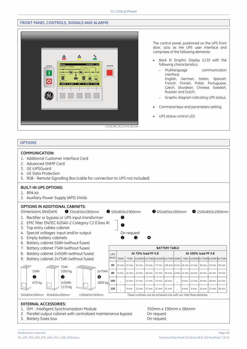
FRONT PANEL CONTROLS, SIGNALS AND ALARMS
The control panel, positioned on the UPS front door, acts as the UPS user interface and comprises of the following elements:
Back lit Graphic Display (LCD) with the following characteristics:
Multilanguage communication interface: English, German, Italian, Spanish, French, Finnish, Polish, Portuguese, Czech, Slovakian, Chinese, Swedish, Russian and Dutch;
Graphic diagram indicating UPS status.
Command keys and parameters setting.
UPS status control LED.
OPTIONS
COMMUNICATION:
1. Additional Customer Interface Card
2. Advanced SNMP Card 3. GE iUPSGuard 4. GE Data Protection 5. RSB - Remote Signalling Box (cable for connection to UPS not included)
BUILT-IN UPS OPTIONS:
1. RPA kit 2. Auxiliary Power Supply (APS) 24Vdc
OPTIONS IN ADDITIONAL CABINETS:
Dimensions (WxDxH): 350x850x1900mm 500x850x1900mm 850x850x1900mm 1500x850x1900mm
1. Rectifier or bypass or UPS input transformer
2. EMC filter EN/IEC 62040-2 Category C2 (Class A)
3. Top entry cables cabinet
4. Special voltages: input and/or output On request5. Empty battery cabinets
6. Battery cabinet 50Ah (without fuses)
7. Battery cabinet 75Ah (without fuses) BATTERY TABLE
8. Battery cabinet 2x50Ah (without fuses) UPS (kVA)
At 75% load PF 0.8 At 100% load PF 0.8
9. Battery cabinet 2x75Ah (without fuses) 50Ah 75Ah 2x50Ah 2x75Ah 4x50Ah 4x75Ah 50Ah 75Ah 2x50Ah 2x75Ah 4x50Ah 4x75Ah
50Ah
670 kg
75Ah
1000 kg
2x50Ah
1170 kg
2x75Ah
1800 kg
60 13 min. 22 min. 31 min. 53 min. 77 min. 139 min. 9 min. 16 min. 22 min. 36 min. 53 min. 95 min.
80 9 min. 15 min. 22 min. 36 min. 52 min. 95 min. 6 min. 11 min. 16 min. 26 min. 36 min. 70 min.
100 _ 12 min. 17 min. 27 min. 37 min. 65 min. _ 8 min. 12 min. 20 min. 28 min. 45 min.
120 _ 9 min. 13 min. 22 min. 32 min. 51 min. _ 6 min. 9 min. 16 min. 22 min. 36 min.
500x850x1900mm 850x850x1900mm 1500x850x1900mm These runtimes can be achieved only with our High Rate batteries.
EXTERNAL ACCESSORIES: 1. ISM - Intelligent Synchronization Module 350mm x 190mm x 584mm 2. Parallel output cabinet with centralized maintenance bypass On request 3. Battery fuses box On request
SGSE_060-120_S1_OPT_cabinet 500_01 SGSE_160-300_OPT_B1 cabinet_01
SGSE_160-300_OPT_B2 cabinet_01
Critical Power
Modifications reserved Page 6/6
GE_UPS_TDS_SGS_PCE_60K_M12_1GB_V050.docx Technical Data Sheet SG Series 60 & 120 PurePulse™ CE S1
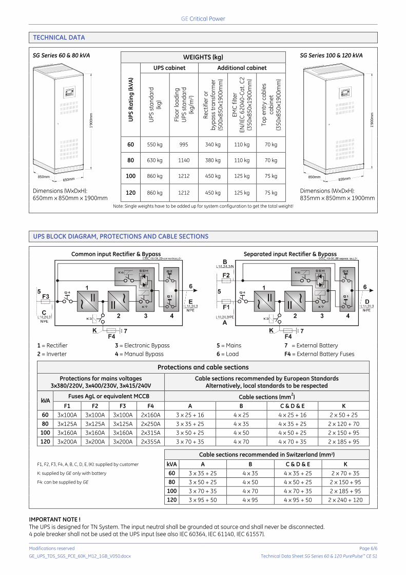
TECHNICAL DATA
SG Series 60 & 80 kVA
Dimensions (WxDxH): 650mm x 850mm x 1900mm
WEIGHTS (kg) SG Series 100 & 120 kVA
Dimensions (WxDxH): 835mm x 850mm x 1900mm
UP
S R
ati
ng
(kV
A)
UPS cabinet Additional cabinet
UP
S s
tan
da
rd
(kg
)
Flo
or
loa
din
g
UP
S s
tan
da
rd
(kg
/m2)
Re
ctif
ier
or
by
pa
ss t
ran
sfo
rme
r
(50
0x8
50
x19
00
mm
)
EM
C f
ilte
r E
N/I
EC
62
04
0-C
at.
C2
(3
50
x85
0x1
90
0m
m)
Top
en
try
ca
ble
s c
ab
ine
t (3
50
x85
0x1
90
0m
m)
60 550 kg 995 340 kg 110 kg 70 kg
80 630 kg 1140 380 kg 110 kg 70 kg
100 860 kg 1212 450 kg 125 kg 75 kg
120 860 kg 1212 450 kg 125 kg 75 kg
Note: Single weights have to be added up for system configuration to get the total weight!
UPS BLOCK DIAGRAM, PROTECTIONS AND CABLE SECTIONS
Common input Rectifier & Bypass Separated input Rectifier & Bypass
1 = Rectifier 3 = Electronic Bypass 5 = Mains 7 = External Battery
2 = Inverter 4 = Manual Bypass 6 = Load F4 = External Battery Fuses
Protections and cable sections
Protections for mains voltages
3x380/220V, 3x400/230V, 3x415/240V Cable sections recommended by European Standards
Alternatively, local standards to be respected
kVA Fuses AgL or equivalent MCCB Cable sections (mm
2)
F1 F2 F3 F4 A B C & D & E K
60 3x100A 3x100A 3x100A 2x160A 3 x 25 + 16 4 x 25 4 x 25 + 16 2 x 50 + 25
80 3x125A 3x125A 3x125A 2x250A 3 x 35 + 25 4 x 35 4 x 35 + 25 2 x 120 + 70
100 3x160A 3x160A 3x160A 2x315A 3 x 50 + 25 4 x 50 4 x 50 + 25 2 x 150 + 95
120 3x200A 3x200A 3x200A 2x355A 3 x 70 + 35 4 x 70 4 x 70 + 35 2 x 185 + 95
Cable sections recommended in Switzerland (mm2)
F1, F2, F3, F4, A, B, C, D, E, (K): supplied by customer kVA A B C & D & E K
K: supplied by GE only with battery 60 3 x 35 + 25 4 x 35 4 x 35 + 25 2 x 70 + 35
F4: can be supplied by GE 80 3 x 50 + 25 4 x 50 4 x 50 + 25 2 x 150 + 95
100 3 x 70 + 35 4 x 70 4 x 70 + 35 2 x 185 + 95
120 3 x 95 + 50 4 x 95 4 x 95 + 50 2 x 240 + 120
IMPORTANT NOTE ! The UPS is designed for TN System. The input neutral shall be grounded at source and shall never be disconnected. 4 pole breaker shall not be used at the UPS input (see also IEC 60364, IEC 61140, IEC 61557).
SGSE_060-080_S1_UPS dimensions_GE_01
850mm650mm
1'9
00
mm
SGSE_100-120_S1_UPS dimensions_GE_01
835mm850mm
1'9
00
mm