Embed Size (px)
Citation preview
©TIMBER QUEENSLAND LIMITED TECHNICAL DATA SHEET 32 WIND TIE-DOWN CONNECTIONS Revised June 2016 Page 1
Even at low wind speed classifications such as non-cyclonic N2, sheet roofed houses will have net wind uplift forces that need to be tied-down with specific tie-down connections. As site wind classifications increase all roof types require specific tie-down. Wind uplift forces increase in proportion to the square of the velocity of the wind so, for example, a site with a wind velocity of 61m/s (C2) will have 50% higher uplift forces than a 50m/s (C1) site. Getting every required tie-down connection right is critical as failure of one link in the tie-down chain can lead to loss of a whole roof in a wind event.
This data sheet addresses common issues with tie-down and support that are regularly seen on building sites. Refer also to TDS 26 - Truss Installation and AS 1684 Part 2 and 3 for more detailed design information.
MACHINE NAILINGCare needs to be taken when using machine driven nails through joist hangers, framing anchors and tie-down straps etc.
All connector manufacturers have specific recommendations on acceptable practices where machine nails are used. These cover minimum edge distances, types and sizes of nails as well as number of nails which usually have to be increased over the supplied standard nails to account for their smaller diameters.
Following extensive consultation with industry, The QBCC recently revised and released their requirements for use of gun nails in metal tie-down connections. This advice which can be accessed at the link below states that only hand nails are to be used in some connectors such as Triple Grips, Multi Grips and Universal Grips.
http://www.qbcc.qld.gov.au/blog/tradie-talk/update-gun-nailing-tie%E2%80%93down-connectors
This advice also provides guidance on acceptable installation practices for where machine driven nails can be used and the nail location requirements. See Figure 1.
Figure 1. – Machine nail location requirements (Source Pryda/QBCC)
RECOMMENDED PRACTICE // JUNE 2016
WIND TIE-DOWN CONNECTIONS – GETTING IT RIGHT
TECHNICAL DATA SHEETISSUED BY TIMBER QUEENSLAND
32
©TIMBER QUEENSLAND LIMITED TECHNICAL DATA SHEET 32 WIND TIE-DOWN CONNECTIONS Revised June 2016 Page 2
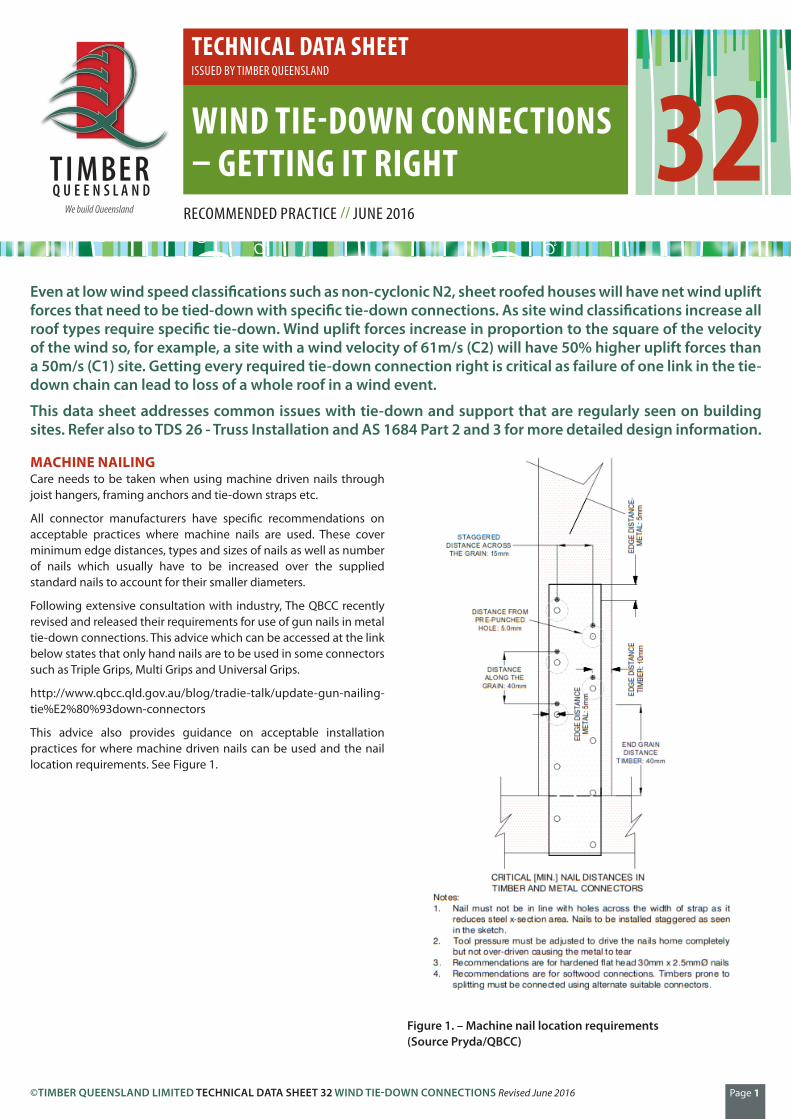
Photograph 1 - Inappropriate practices as nails are too close to strap edge, too close to pre-punched holes and even doubled up. Strap should also have been installed on the inside of frame to enable strap nailing direct to lintel without bending the strap
Photograph 2 - A structurally inadequate and incorrectly installed multi-grip. Nails too close to each other and edge of metal and also, too close to top edge of top plate
WASHERS FOR COACH SCREWS, BOLTS AND TIE-DOWN RODSThe timber framing code, AS 1684 specifies the minimum washer sizes required for coach screws, bolts and tie-down rod connections. The size and thickness of a washer plays an important part in the specified strengths of these connections and the correct size must be used to achieve the connection capacities given in the Standard. Cup-head bolts with standard washers or large washers, do not achieve the same strength as their hex-head equivalents. Table 1 gives the minimum washer sizes required.
TABLE 1: WASHER SIZESCoach screw, bolt, tie-down rod Dia. (mm) Washer Size (mm)
Cup-head bolts Standard washers
M10 38 x 38 x 2.0
M12 50 x 50 x 3.0
M16 65 x 65 x 5.0
TIE-DOWN OF ROOFING SYSTEMS
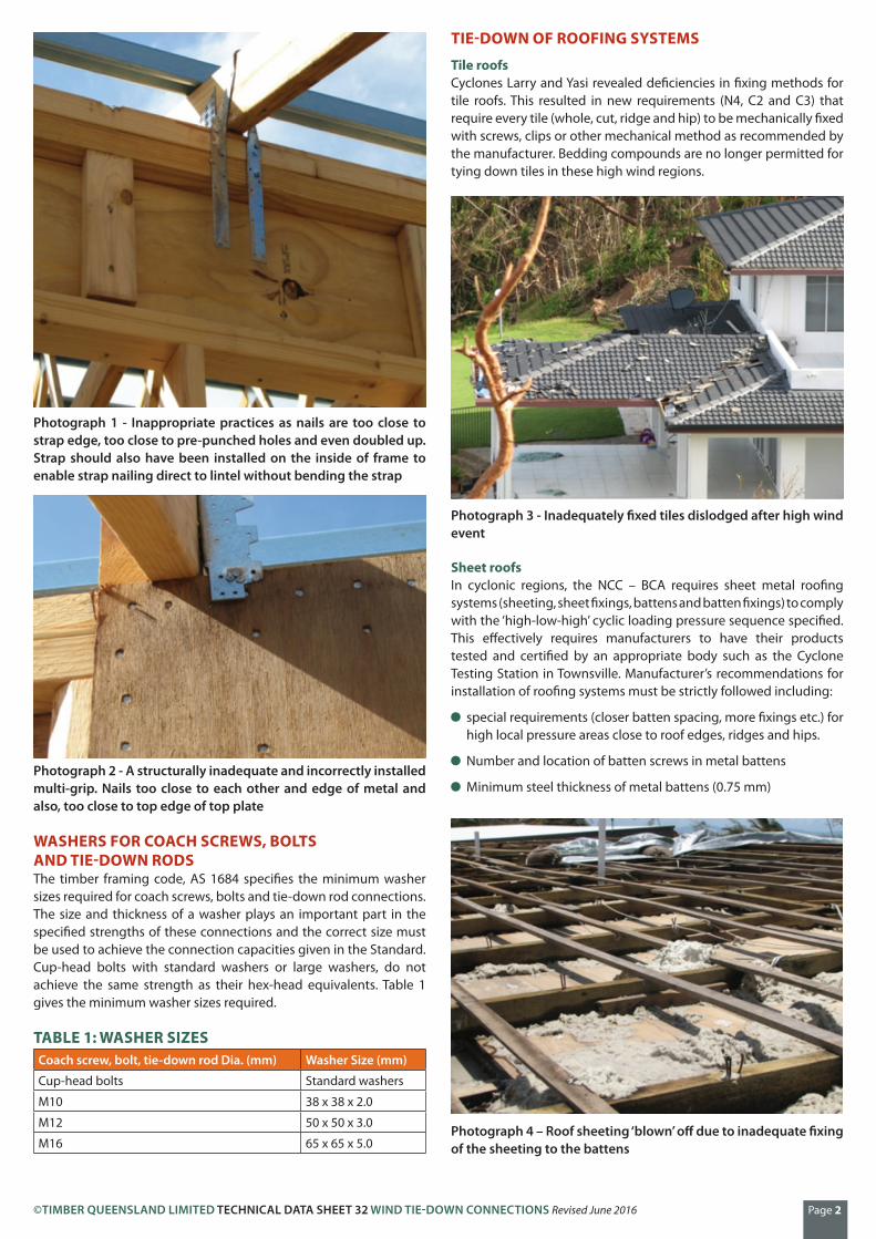
Tile roofsCyclones Larry and Yasi revealed deficiencies in fixing methods for tile roofs. This resulted in new requirements (N4, C2 and C3) that require every tile (whole, cut, ridge and hip) to be mechanically fixed with screws, clips or other mechanical method as recommended by the manufacturer. Bedding compounds are no longer permitted for tying down tiles in these high wind regions.
Photograph 3 - Inadequately fixed tiles dislodged after high wind event
Sheet roofsIn cyclonic regions, the NCC – BCA requires sheet metal roofing systems (sheeting, sheet fixings, battens and batten fixings) to comply with the ‘high-low-high’ cyclic loading pressure sequence specified. This effectively requires manufacturers to have their products tested and certified by an appropriate body such as the Cyclone Testing Station in Townsville. Manufacturer’s recommendations for installation of roofing systems must be strictly followed including:
special requirements (closer batten spacing, more fixings etc.) for high local pressure areas close to roof edges, ridges and hips.
Number and location of batten screws in metal battens
Minimum steel thickness of metal battens (0.75 mm)
Photograph 4 – Roof sheeting ‘blown’ off due to inadequate fixing of the sheeting to the battens
©TIMBER QUEENSLAND LIMITED TECHNICAL DATA SHEET 32 WIND TIE-DOWN CONNECTIONS Revised June 2016 Page 3
Battens to Trusses/Rafters Special attention should be paid to the connection of battens to rafters/trusses particularly at high local pressure areas such as hips. If these connection points are deficient it can result in roofs peeling off.
The joining of battens at supports can be achieved by the methods given in Figure 1, and an acceptable method of joining battens between supporting trusses/rafters is shown in Figure 2.
(a) Butt-join with block fixed to side of rafter/truss
Figure 2 – Joining battens at supports
Batten
Fishplate
2/No. 14 type 17 screws each side of the butt joint
Rafter/ Truss
Batten
Fishplate
Rafter/ Truss
75 mm max.
600 mm min.
Figure 3 – Joining battens between supports
Photograph 5 – Roof sheeting and battens have failed due to nailed batten fixing where screws should have been used
TRUSS SUPPORT AND TIE-DOWN
SupportsTrusses must be supported (and tied down) at specified points, which unless specially designed, will occur at heels and at panel points on the bottom chords. Particular care should be taken to ensure this occurs with cantilevered trusses and long span or girder trusses that may be designed to also have internal support points.
Photograph 6 – Girder truss incorrectly supported by an offset wall
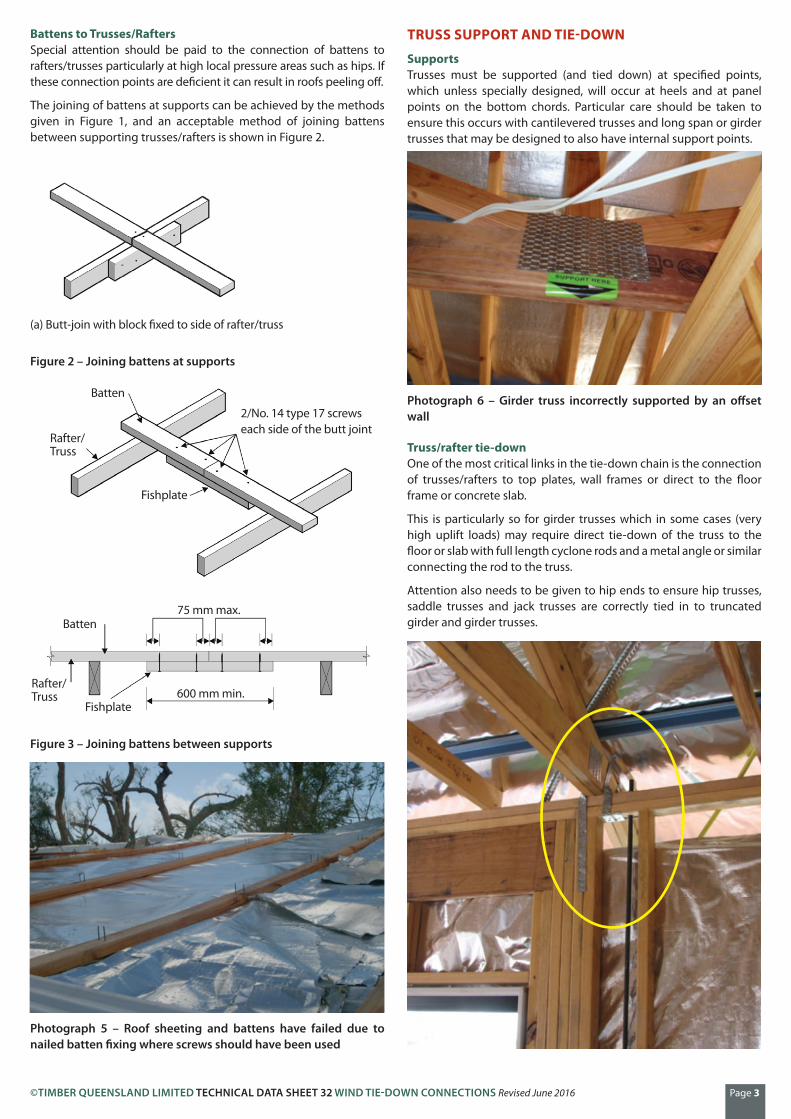
Truss/rafter tie-downOne of the most critical links in the tie-down chain is the connection of trusses/rafters to top plates, wall frames or direct to the floor frame or concrete slab.
This is particularly so for girder trusses which in some cases (very high uplift loads) may require direct tie-down of the truss to the floor or slab with full length cyclone rods and a metal angle or similar connecting the rod to the truss.
Attention also needs to be given to hip ends to ensure hip trusses, saddle trusses and jack trusses are correctly tied in to truncated girder and girder trusses.

©TIMBER QUEENSLAND LIMITED TECHNICAL DATA SHEET 32 WIND TIE-DOWN CONNECTIONS Revised June 2016 Page 4
Photograph 7 – Double straps connecting girder truss to top plate and jamb studs (strap to jamb stud should have been centrally located on stud). Cyclone rod correctly located within 100 mm of truss tie-down
Photograph 8 – Inadequate connection of jack and hip trusses to girder truss in a C2 site
Detail E2 - Jack Truss to Hip Truss (maximum jack station 2400mm)
One Creeper Connector (CC200L/R) with 6/2.8mm x 30mm reinforced head nails into each face
Creeper Connector CC200
Jack BC
Hip BC
Hip TC
Jack TC
Figure 4 – Typical jack to hip truss connection as specified in AS 4440 for N4, C2 and C3 Wind Classifications
TIE-DOWN AT OPENINGS
Over openingsFor N2 sheet roofs and all sheet and tile roofs N3 and greater, top plates will have net uplift forces applied to them where trusses/rafters are connected directly to the top plate and not directly to the floor frame or slab via anchor rods. The top plates will therefore be required to be able to span (bending in an upward direction) between top plate tie-down points installed in the wall frame to resist uplift.
At openings, tie-down of the top plates can only occur at the sides of the opening. Therefore, trusses and rafters that are tied down over the opening are required to be tied to the lintel to transfer uplift loads back to the tie-down points either side of the opening. Top plates, typically being a double standard plate are not capable of spanning any great distance (i.e. openings typically greater than 1200 mm), in
uplift, between tie-down points either side of openings.
For these situations, options for tying trusses/rafters to lintels over openings include:
Tie trusses/rafters to top plate and then within 100 mm of this tie top plates to lintels with strap, bolts or similar
Tie trusses/rafters direct to lintel.
Photograph 9 – Incorrect practice for tying down over openings as top plates not tied to lintel
Photograph 10 – Truss tied direct to top plate and lintel, but strap bent through too great an angle to be effective
[Note: The truss to the far RHS is tied to a block nailed to the lintel. This would be satisfactory as the strap is not bent as long as block had sufficient nails into lintel.]
At sides of openingsA practice that has mistakenly been considered acceptable (mainly in non-cyclonic areas) has been the use of plywood at sides of openings to effect tie-down of top plates to bottom plates. Plywood bracing can be used for tie-down in the general run of wall frames within prescribed limits, but is not suitable for tie-down at sides of openings because at least 300 mm of ply (top plate to bottom plate) is required either side of the truss/rafter being tied down at the side of the opening and in most circumstances this cannot be achieved. Sides of openings must be tied down by other means.
©TIMBER QUEENSLAND LIMITED TECHNICAL DATA SHEET 32 WIND TIE-DOWN CONNECTIONS Revised June 2016 Page 5
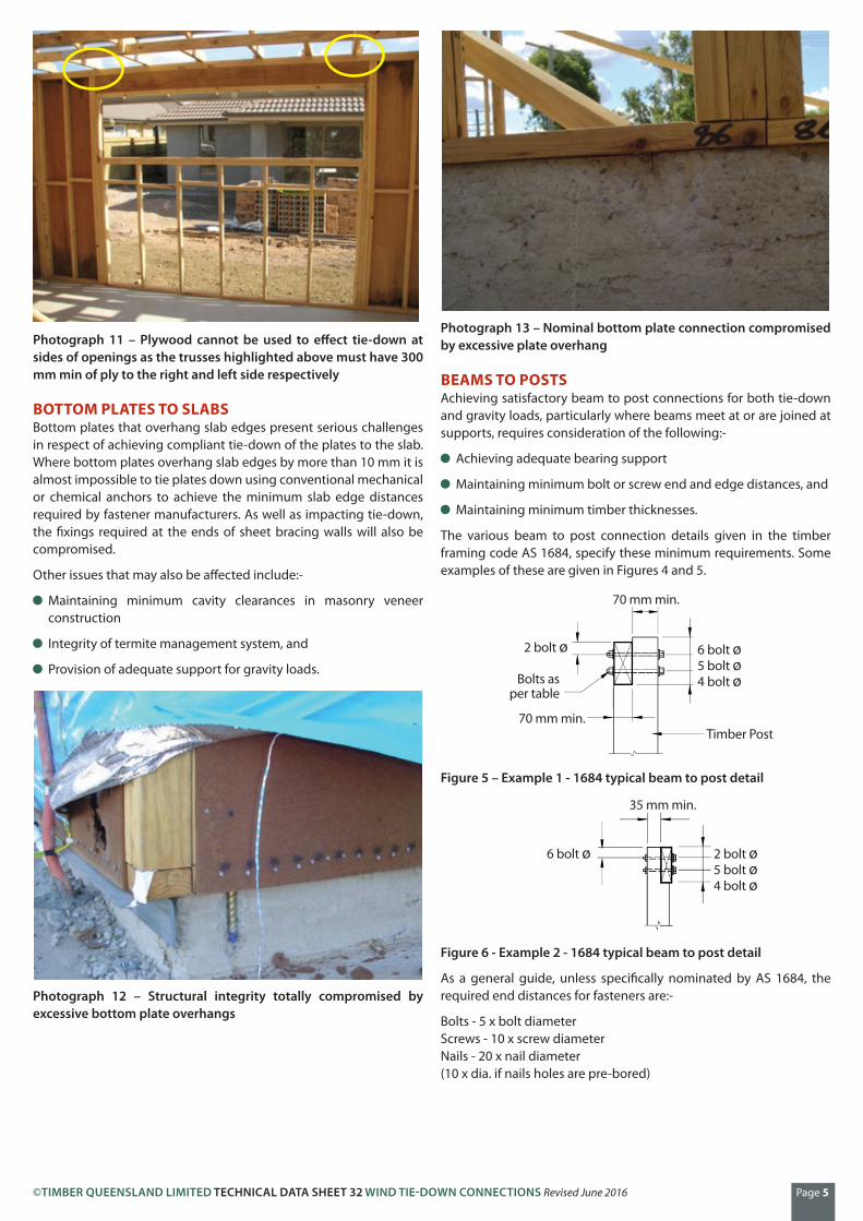
Photograph 11 – Plywood cannot be used to effect tie-down at sides of openings as the trusses highlighted above must have 300 mm min of ply to the right and left side respectively
BOTTOM PLATES TO SLABSBottom plates that overhang slab edges present serious challenges in respect of achieving compliant tie-down of the plates to the slab. Where bottom plates overhang slab edges by more than 10 mm it is almost impossible to tie plates down using conventional mechanical or chemical anchors to achieve the minimum slab edge distances required by fastener manufacturers. As well as impacting tie-down, the fixings required at the ends of sheet bracing walls will also be compromised.
Other issues that may also be affected include:-
Maintaining minimum cavity clearances in masonry veneer construction
Integrity of termite management system, and
Provision of adequate support for gravity loads.
Photograph 12 – Structural integrity totally compromised by excessive bottom plate overhangs
Photograph 13 – Nominal bottom plate connection compromised by excessive plate overhang
BEAMS TO POSTSAchieving satisfactory beam to post connections for both tie-down and gravity loads, particularly where beams meet at or are joined at supports, requires consideration of the following:-
Achieving adequate bearing support
Maintaining minimum bolt or screw end and edge distances, and
Maintaining minimum timber thicknesses.
The various beam to post connection details given in the timber framing code AS 1684, specify these minimum requirements. Some examples of these are given in Figures 4 and 5.
70 mm min.
Timber Post
6 bolt ø5 bolt ø4 bolt ø
70 mm min.
Bolts as per table
2 bolt ø
Figure 5 – Example 1 - 1684 typical beam to post detail
35 mm min.
2 bolt ø5 bolt ø4 bolt ø
6 bolt ø
Figure 6 - Example 2 - 1684 typical beam to post detail
As a general guide, unless specifically nominated by AS 1684, the required end distances for fasteners are:-
Bolts - 5 x bolt diameterScrews - 10 x screw diameterNails - 20 x nail diameter(10 x dia. if nails holes are pre-bored)
©TIMBER QUEENSLAND LIMITED TECHNICAL DATA SHEET 32 WIND TIE-DOWN CONNECTIONS Revised June 2016 Page 6
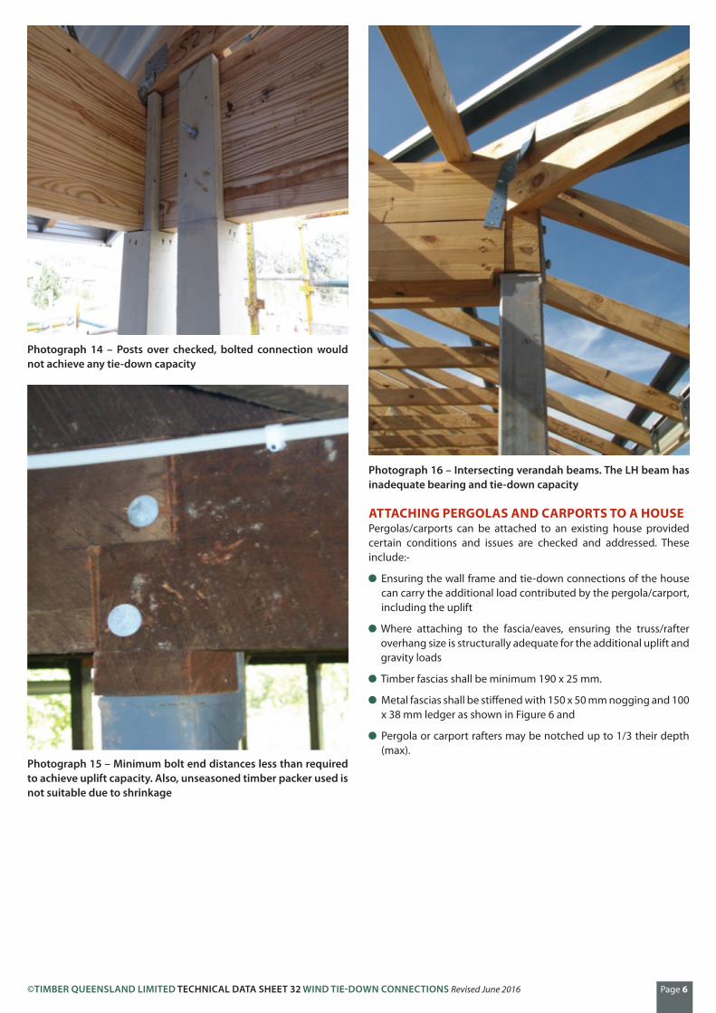
Photograph 14 – Posts over checked, bolted connection would not achieve any tie-down capacity
Photograph 15 – Minimum bolt end distances less than required to achieve uplift capacity. Also, unseasoned timber packer used is not suitable due to shrinkage
Photograph 16 – Intersecting verandah beams. The LH beam has inadequate bearing and tie-down capacity
ATTACHING PERGOLAS AND CARPORTS TO A HOUSEPergolas/carports can be attached to an existing house provided certain conditions and issues are checked and addressed. These include:-
Ensuring the wall frame and tie-down connections of the house can carry the additional load contributed by the pergola/carport, including the uplift
Where attaching to the fascia/eaves, ensuring the truss/rafter overhang size is structurally adequate for the additional uplift and gravity loads
Timber fascias shall be minimum 190 x 25 mm.
Metal fascias shall be stiffened with 150 x 50 mm nogging and 100 x 38 mm ledger as shown in Figure 6 and
Pergola or carport rafters may be notched up to 1/3 their depth (max).
©TIMBER QUEENSLAND LIMITED TECHNICAL DATA SHEET 32 WIND TIE-DOWN CONNECTIONS Revised June 2016 Page 7
Whilst every effort is made to ensure the accuracy of advice given, Timber Queensland Limited cannot accept liability for loss or damage arising from the use of the information supplied.
Phone (07) 3358 7900Fax (07) 3358 7999PO Box 231, Kedron Qld [email protected]
Timber Queensland LimitedACN 092 686 756 | ABN 50 092 686 756
30 Boothby Street, Kedron Brisbane Queensland 4031
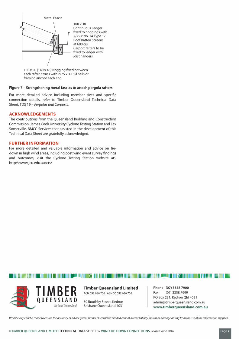
Metal Fascia
100 x 38Continuous Ledger�xed to noggings with2/75 x No. 14 Type 17Roof Batten Screensat 600 crs.Carport rafters to be�xed to ledger withjoist hangers.
150 x 50 (140 x 45) Nogging �xed betweeneach rafter / truss with 2/75 x 3.15Ø nails orframing anchor each end.
Figure 7 – Strengthening metal fascias to attach pergola rafters
For more detailed advice including member sizes and specific connection details, refer to Timber Queensland Technical Data Sheet, TDS 19 – Pergolas and Carports.
ACKNOWLEDGEMENTS The contributions from the Queensland Building and Construction Commission, James Cook University Cyclone Testing Station and Lex Somerville, BMCC Services that assisted in the development of this Technical Data Sheet are gratefully acknowledged.
FURTHER INFORMATIONFor more detailed and valuable information and advice on tie-down in high wind areas, including post wind event survey findings and outcomes, visit the Cyclone Testing Station website at:- http://www.jcu.edu.au/cts/