Embed Size (px)
Citation preview

66
Technical Data7
Dielectric strength
Internal resistance and power consumption
Circuit Withstand voltage (at 50/60 Hz)
Main circuit Between terminals, AC3500V for 1 minute 12kVterminal group to earth
Auxiliary switches For general service Terminal group to earth AC2500V for 1 minute 6kV
For microload Terminal group to earth AC2000V for 1 minute 4kV
Position switches Terminal group to earth AC2000V for 1 minute 4kV
Over-current release (OCR) Terminal group to earth AC2000V for 1 minute 4kV
Power supply for undervoltage/ Terminal group to earth AC2500V for 1 minute 6kVreverse power trip function
Other accessories Terminal group to earth AC2000V for 1 minute 4kV
Note: The values shown above are those measured on phase connections and cannot be applied to control terminals on the ACB.
Rated Impulse withstandvoltage Uimp
Co
ntr
ol
cir
cu
its
• Standard Series
• High fault Series
The max. rated current [In] depends on the main circuit terminal arrangement
Type AR208S AR212S AR216S AR220S AR325S AR332S AR440SB AR440S AR650S AR663S
Rated current (A) 800 1250 1600 2000 2500 3200 4000 4000 5000 6300
DC internal resistance per pole (mΩ) 0.033 0.033 0.028 0.024 0.014 0.014 0.017 0.014 0.012 0.010
Power consumption for 3 poles (W) 64 155 215 288 263 430 816 672 900 1190
Type AR212H AR216H AR220H AR316H AR320H AR325H AR332H AR420H AR440H AR663H
Rated current (A) 1250 1600 2000 1600 2000 2500 3200 2000 4000 6300
DC internal resistance per pole (mΩ) 0.024 0.024 0.024 0.014 0.014 0.014 0.014 0.014 0.014 0.010
Power consumption for 3 poles (W) 113 184 288 108 168 263 430 168 672 1190
Based Standard
JIS C 8201-2-1 Ann.1 Ann.2IEC60947-2, EN60947-2AS3947.2
ANSI C37.13NEMA, SG-3
TypeTerminal arrangement
Horizontal terminals
Vertical terminals
Front connections
Horizontal terminals
Vertical terminals
Front connections
AR208SAR212SAR216SAR220SAR325SAR332SAR440SBAR440SAR650SAR663SAR212HAR216HAR220HAR316HAR320HAR325HAR332HAR420HAR440HAR663H
80012501600200024302790
————
1250160020001600200024302790
———
8001250160020002500320040004000500063001250160020001600200025003200200040006300
80012501600200025003150
——————————————
80012501540167022302700
————
1250154016701600200022302700
———
8001250160020002500320033103700470056801250160020001600200025003200
37005680
80012501570183024302890
——————————————
Terminal arrangement
Ambient temperature 40 °C
Note 1: If different type of terminal arrangement are used for line and load sides refer to the ratings for the horizontal terminals.Note 2: Front connection can not be specified with the different types of terminal arrangement for line and load sides.¶: Contact TERASAKI for the details.
Note: Above figures are based on the calculation of 3I2R. For more information please contact TERASAKI.

67
Derating
Based Ambient Type AR208S AR212S AR216S AR220S AR325S AR332S AR440SB AR440S AR650S AR663SStandards temperature Connecting 2X50X5t 2X80X5t 2X100X5t 3X100X5t 2X100X10t 3X100X10t 4X150X10t 4X150X6t 3X200X10t 4X200X10t
(°C) bar sizes
40 (Standard ambient 800 1250 1600 2000 2500 3200 4000 4000 5000 6300 temperature)
45 800 1250 1600 2000 2500 3200 4000 4000 5000 6300
50 800 1250 1600 2000 2500 3200 3940 4000 4950 6000
55 800 1200 1540 1820 2500 2990 3820 3940 4710 5680
60 800 1150 1460 1740 2400 2850 3690 3760 4450 537040(Standard ambient 800 1250 1540 2000 2500 3200 3310 3700 4700 5680 temperature)
45 800 1190 1470 1960 2500 3010 3200 3580 4450 5370
50 800 1130 1390 1860 2440 2860 3100 3470 4180 5050
55 790 1070 1310 1750 2300 2690 2980 3350 3900 4710
60 740 1000 1230 1640 2150 2520 2870 3140 3610 4350
Note: The values are applicable for both Draw-out type and Fixed type.The values of AR208S, AR212S and AR216S are for horizontal terminals on both line and load side.The values of AR220S, AR325S, AR332S, AR440SB, AR440S, AR650S and AR663S are for vertical terminals on both line and load side.Above figures are subject to the design of the enclosure and rating of busbar.
• Standard Series
Based Ambient Type AR212H AR216H AR220H AR316H AR320H AR325H AR332H AR420H AR440H AR663HStandards temperature Connecting 2X80X5t 2X100X5t 3X100X5t 2X100X5t 3X100X5t 2X100X10t 3X100X10t 3X100X5t 4X150X6t 4X200X10t
(°C) bar sizes40 (Standard ambient 1250 1600 2000 1600 2000 2500 3200 2000 4000 6300 temperature)
45 1250 1600 2000 1600 2000 2500 3200 2000 4000 6300
50 1250 1600 2000 1600 2000 2500 3200 2000 4000 6000
55 1250 1600 1820 1600 2000 2500 2990 2000 3940 5680
60 1250 1550 1740 1600 2000 2400 2850 2000 3760 537040(Standard ambient 1250 1600 2000 1600 2000 2500 3200 2000 3700 5680 temperature)
45 1250 1600 1960 1600 2000 2500 3010 2000 3580 5370
50 1250 1600 1860 1600 2000 2440 2860 2000 3470 5050
55 1250 1510 1750 1600 1950 2300 2690 2000 3350 4710
60 1240 1420 1640 1550 1830 2150 2520 2000 3140 4350
Note: The values are applicable for both Draw-out type and Fixed type.The values are for vertical terminals on both line and load side.Above figures are subject to the design of the enclosure and rating of busbar.
• High fault Series
JIS C 8201-2-1Ann.1 Ann.2IEC60947-2EN 60947-2AS3947.2
NEMA, SG-3ANSI C37.13
JIS C 8201-2-1Ann.1 Ann.2IEC60947-2EN 60947-2AS3947.2
NEMA, SG-3ANSI C37.13

68
Application Data7
What Is Discrimination?
Discrimination, also called selectivity, is the co-ordination of protective devices such that a
fault is cleared by the protective device installed immediately upstream of the fault, and by
that device alone.
Total discriminationDiscrimination is said to be total if the downstream circuit breaker opens and the upstream
circuit breaker remains closed. This ensures maximum availability of the system.
Partial discriminationDiscrimination is partial if the above condition is not fulfiled up to the prospective short-
circuit current, but to a lesser value, termed the selectivity limit current (Is).
Above this value both circuit breakers could open, resulting in loss of selectivity
upstream
circuit
breaker
downstream
circuit
breaker
fault
current
X
X
How To Read The Discrimination Tables
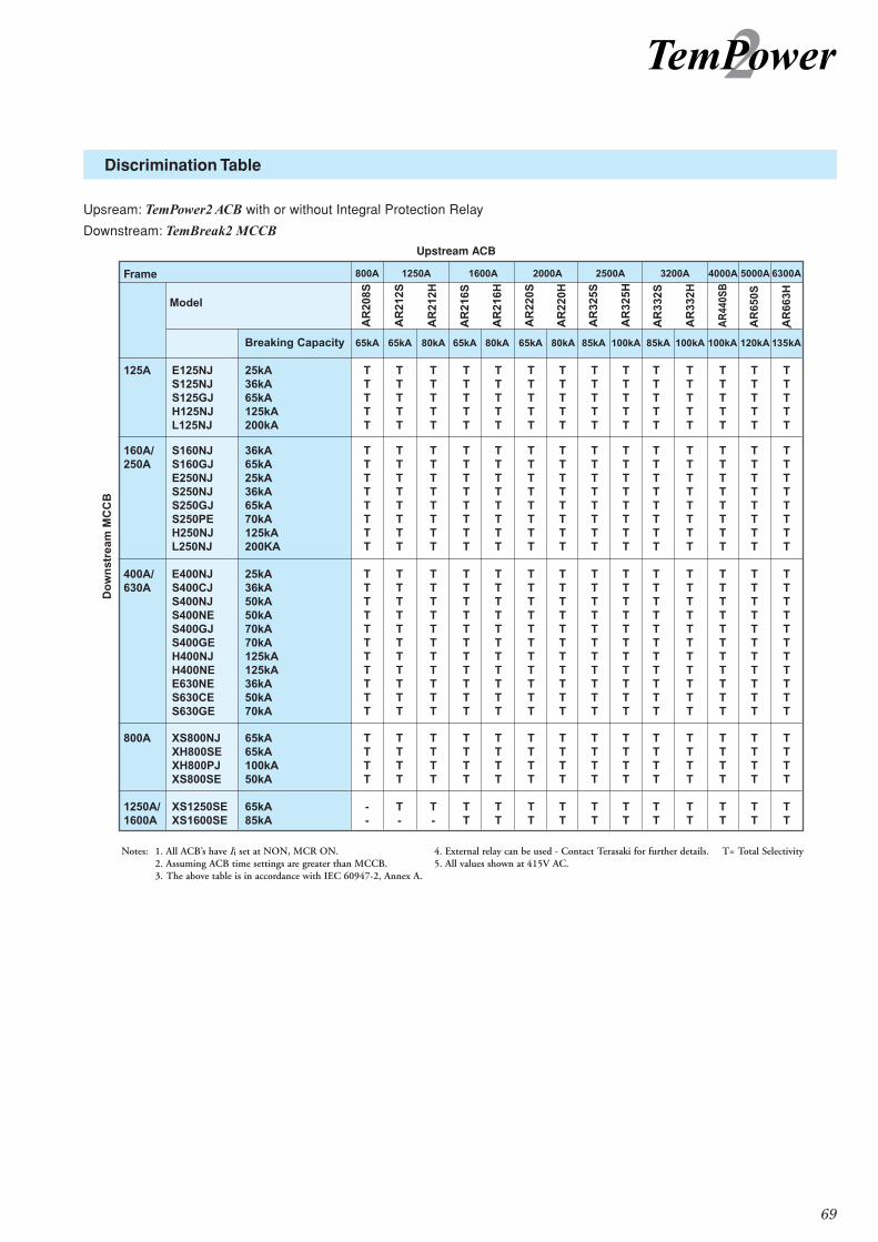
Boxes containing the letter “T” indicate total discrimination between the relevant upstream and downstream circuit-breakers. Total
discrimination applies for all fault levels up to the breaking capacity of the upstream or the downstream circuit breaker, whichever is
the lesser.
For the other boxes, discrimination is either partial or there is no discrimination.
Worked Examples
Q (1) A main switchboard requires a 1600A ACB feeding a 400A MCCB.The fault level is 65kA. What combination of
protective devices would provide total discrimination?
A (1) A TemPower2 ACB AR216S feeding a TemBreak2 S400GJ would provide total discrimination up to 65kA. See page 69
Note: Discrimination would be total whether the TemPower2 ACB had an integral or external protection relay because Icw
(1s) = Ics Most other ACBs have Icw(1s) < Ics.
69
Discrimination Table
Upsream: TemPower2 ACB with or without Integral Protection Relay
Downstream: TemBreak2 MCCB
415V
Upstream ACB

70
Discrimination with ‘T’ type fuses
The following table should be used as a guide when selecting Terasaki Tempower2 Air Circuit Breakers and fuses (BS88/
IEC60269) which are immediately downstream from a transformer.
In and IR are set to the full rated current of the transformer, and tR, Isd and tsd are at standard transformer settings.
Listed are the maximum fuse ratings that can be used when downstream from a given ACB at these settings.
Also included are the maximum fuse ratings that can be used downstream when tR, Isd and tsd are at their maximum settings.
All information listed is based on a transformer secondary voltage of 415V.
> The above ‘In’ settings are based on 100% of Rated Current (Ict).
> Table Reference : IR - Long Time Delay Pickup Current, tR - Long Time Delay Time Setting, Isd - Short Time Delay Pickup Current, tsd - Short Time Delay Time Setting.
Notes:
Note:1 It is possible to increase the maximum fuse rating by utilising the ‘ramp’ facility on the on the TemPower2 Protection Relay (AGR).
Note:2 Information on fuses above 1250A rating was not available.
Note:3 All ACBs have Ii (Instantanious) set to NON. (MCR can be set to ON)
Please note the above table is meant only for guidance, individual installations should have a specific discrimination study undertaken.
Application Data7

71
The TemTransfer is a fully configurable Automatic Changeover Controller (ACC). It is designed to monitor the incoming AC
mains supply (1 or 3 phases) for under/over voltage and under/over frequency. Should these fall out of limits, the module will
issue a start command to the generating set controller. Once the set is available and producing an output within limits the ACC
will control the transfer devices and switch the load from the mains to the generating set. Should the mains supply return to
within limits the module will command a return to the mains supply and shut down the generator after a suitable cooling run.
Various timing sequences are used to prevent nuisance starting and supply breaks.
TemTransfer is compatible with TemPower2 ACBs, TemBreak2 MCCBs and TemContact contactors.
Terasaki can supply TemTransfer pre-configured to specification, or unconfigured with an optional interface kit.
Configuration is by PC based software and the interface kit using an FCC68 socket on the rear of the module. This allows
rapid and secure configuration of the module. The FCC68 socket also provides full real-time diagnostics on the status of the
ACC, its inputs and outputs.
Configuration and connection options allow for a wide range of higher functions such as ‘Auto start inhibit’, ‘Manual restore to
mains’, ‘Load inhibit’(both mains and gen-set), ‘Lamp test’, Push-button transfer control, External mains or Gen-set failure inputs, etc.
The four position key-switch allows for mode selection:-
• Auto Mode
• Auto mode with manual return to Mains
• Run generator off load
• Run generator on load
A clear mimic diagram with ‘International’ symbols and LEDs provide clear
indication of supply availability and load switching status. Further LED
indication is provided for ‘Start delay in progress’ and ‘Mains return timer
active’. Two user configurable LED’s are provided to allow the user to display
specific states (defaulted to indicate that the closing procedure of the Mains
or Generator circuit breaker has been started).
Five user configurable relays are provided to allow control of contactors,
different circuit breaker types and engine control modules and alarm
systems.
The controller features a self seeking power supply which will utilise power
from the Mains AC supply or the Generator AC supply. A DC supply to the module is not essential for basic operation, though
some ‘higher’ functions require it (such as system diagnostics).
The module is mounted in a robust plastic case, connection to the module is via plug and socket connectors.
Accessories For Dual Supply Changeover Systems Accessories
TemTransfer Automatic Changeover Controller

72
(Not available on AR4 & AR6 ACBs)
For AGR-31B please state system voltage -
Specify generator full load current (In) if applicable -
Back lit LCD for AGR-21B, 22B (option)
Volts
Amps
TERASAKI ACB TYPE
ENTER CIRCUIT BREAKER TYPE - Type S, H or SB
ENTER RATED CURRENT - Amps
ENTER SENSOR KIT RATING - Ict
ENTER NUMBER OF POLES
AR FOR EXAMPLE - AR
ONLY ENTER A VALUE IF DIFFERENT FROM RATED CURRENT
325
1.TemPower 2 ACB: Enter your choice in the boxes provided (Refer to the catalogue for ratings and specfications)1.TemPower 2 ACB: Enter your choice in the boxes provided (Refer to the catalogue for ratings and specfications)
Order Form8 Page 1 of 2

73
Order Form8 Page 2 of 2
European market only European market only
For AR 2, 3 & 440SB
For AR 2, 3, 4 & 6
AWR-1B
AWR-2B
IP55 Transparent Cover
Fixing Blocks
Test Jumper
Auto-Discharge
Lifting Plates
OCR Checker ANU-1
OCR test interface unit, type ANU-2
Main Shutter Padlock Device
IP3X Chassis Protection — European market only
Lifter Loader
Body (Portable Part) Chassis (Permanent Part)
Type C (1)
Type B (2)
Type D (3)
Type A (4)
Horizontal Mechanical Interlock One of two breakers can be turned on.
One or two of three breakers can be turned on.
One of three breakers can be turned on.
Br2 is interlocked with both Br1 and Br3.

AUG. 2008 Ref No. 08-I55EbRatings and specifications in this catalogue may be subject to change without notice
C/ Galileu Galilei, 19-21P. Ind. Coll De La Manya E-08403 Granollers Barcelona, Spain


![DATA SHEET: TEMPOWER2 ACB - Terasaki Data... · • for generator protection use [In] is generator rated current. AC RATED INSULATION VOLTAGE [Ui](V. 50/60Hz) RATED OPERATIONAL VOLTAGE](https://img.pdfslide.net/doc/110x75/5e708caa6c35e736ff3962d0/data-sheet-tempower2-acb-data-a-for-generator-protection-use-in-is-generator.jpg)