Embed Size (px)
Citation preview

Technical Description A 924 BHydraulic Excavator litronic̀
Machine for Industrial ApplicationsOperating Weight 44,950–58,000 lbsEngine Output 173 HP (127 kW)

Technical Data
EngineRating per ISO 9249 ________ 173 HP (127 kW) at 2000 RPMModel ____________________________ Liebherr D 924 TI-EType ________________________________ 4 cylinder in-line
Bore/Stroke ________________ 4.8/5.6 inDisplacement ____________ 1.74 gal
Engine operation ______________ 4-stroke dieseldirect injectionturbo-chargedafter-cooledreduced emissions
Cooling system ________________ water radiator with integrated engine oilcooler
Air cleaner ______________________ dry-type air cleaner with pre-cleaner,primary and safety elements
Fuel tank ________________________ 95 galEngine idling ____________________ sensor controlledElectrical system
Voltage ______________________ 24 VBatteries ____________________ 2 x 110 Ah/12 VStarter ______________________ 24 V/5.4 kWAlternator __________________ 24 V/55 A
Swing DriveDrive ______________________________ Liebherr swashplate motor with integrated
brake valve and torque controlTransmission ____________________ Liebherr compact planetary reduction gearSwing ring ______________________ Liebherr sealed single race ball bearing
swing ring, internal teethSwing speed ____________________ 0–8,0 R.P.M.Swing torque __________________ 74 kNmHolding brake __________________ wet discs (spring applied – pressure
released)Option ____________________________ pedal controlled positioning brake
Operator’s CabCab ________________________________ built from deep drawn components, resil-
iently mounted, sound insulated, tintedwindows, front window stores overhead,door with sliding window
Operator’s seat ________________ fully adjustable, shockabsorbing suspen-sion, adjustable to operator’s weight andsize, 6-way adjustable seat
Joysticks ________________________ integrated into adjustable seat consolesMonitoring ______________________ menu driven query of current operating
conditions via the LCD display. Automaticmonitoring, display, warning (acousticaland optical signal) and saving machinedata, for example, engine overheating, lowengine oil pressure or low hydraulic oil level
Heater/Airconditioner ________ combined hotwater/airconditioner with dustfilter for fresh or circulated airflow
Noise emissionISO 6396 ________________________ LpA (inside cab) = 75 dB(A)2000/14/EC______________________ LwA (surround noise) = 104 dB(A)
UndercarriageDrive ______________________________ variable flow swashplate motor with auto-
matic brake valveTransmission ____________________ oversized two speed power shift trans-
mission with additional creeper speedTravel speed ____________________ 0– 1.6 mph (creeper speed off road)
0– 3.1 mph (off road)0– 5.6 mph (creeper speed on road)0–12.4 mph (road travel)
Axles ______________________________ 88,200 lbs excavator axles; automatic oroperator controlled front axle oscillationlock
Brakes ____________________________ wet, maintenance-free multi disc brakesact as travel brakes or digging locks.Spring applied/pressure released
Stabilization ____________________ prop up blade (adjustable during travel fordozing)2 point outriggers4 point outriggers
AttachmentType ________________________________ resistant steel platesHydraulic cylinders __________ Liebherr cylinders with special seal system.
Shock absorptionPivots ____________________________ sealed, low maintenanceLubrication ______________________ via grease distributor and a grease nipple
installed on the uppercarriage
Hydraulic ControlsPower distribution ____________ via control valve with integrated safety
valves, simultaneous and independentoperation of travel drive, swing drive and
Control type workAttachment andswing ________________________ proportional via joystick leversTravel ________________________ proportional via foot pedal
Additional functions __________ via switch and/or proportional foot pedals
Hydraulic SystemHydraulic pump ________________ Liebherr, variable displacement, swash-
plate pumpMax. flow __________________ 2 x 53 gpmMax. hydr. pressure ____ 5075 PSI
Hydraulic pumpregulation and control ______ Liebherr-Synchron-Comfort-system (LSC)
with electronic engine speed sensing regu-lation, pressure and flow compensation,load sensing and torque controlled swingdrive priority
Hydraulic tank __________________ 61 galHydraulic system ______________ max. 116 galHydraulic oil filter ______________ 1 full flow filter in return line with integrated
fine filter area (5 µm)Hydraulic oil cooler __________ compact cooler, consisting of a water
cooler, sandwiched with hydraulic oil coolerand after-cooler cores and hydrostaticallydriven fan
MODE selection ______________ adjustment of machine performance andthe hydraulics via a mode selector tomatch application
LIFT __________________________ for liftingFINE ________________________ for precision work and lifting through very
sensitive movementsECO __________________________ for especially economical and environ-
mentally friendly operationPOWER ____________________ for maximum digging power and heavy
duty jobsSuper-Finish ____________________ adjustable working speed for precision
workR.P.M. adjustment ____________ stepless adjustment of engine output via
the r.p.m. at each selected modeAdditionnal menu ____________ 4 adjustable oil flows, for optional acces-
sories
2 TD A 924 B Litronic Machine for Industrial Applications

Dimensions
TD A 924 B Litronic Machine for Industrial Applications 3
ft-inA 8’ 2”B 9’ 0”B1 13’12”B2 9’ 0”C 10’ 6”D 8’11”E 9’ 3”H 8’ 4”I2 1’ 5”J2 1’ 9”K 4’ 3”L 9’ 0”M 4’ 1”Q 1’ 2”R1 13’11”R2 24’10”T1 3’ 5”T2 4’ 7”T4 3’11”U2 16’ 1”U4 16’ 4”Z 17’ 9”Z1) 16’ 3”
1) 4 point outriggersE = Tail radius
Tires 11.00-20
Indus- Industrial-Type Industrial-Typetrial Straight Boom Gooseneck BoomStick 22’3” 21’4”
Prop up 4 pt. Prop up 4 pt.blade outr. blade outr.
ft-in ft-in ft-in ft-in ft-inV 13’1” – – 22’4” 22’4”
16’5” 20’ 4” 20’8”* 19’2” 19’0”*19’8” 18’ 8” 18’6”* – –
W 13’1” – – 9’2” 9’2”16’5” 7’ 9” 8’8”* 9’4” 9’2”*19’8” 12’10” 12’4”* – –
X 13’1” – – 31’8” 31’8”16’5” 32’ 8” 32’8”* 31’8” 31’8”*19’8” 32’ 2” 32’4”* – –
Dimensions are with attachment over steering axle* Attachment over digging axle for shorter transport dimensions
M
L
U4
V
W
D
E
X
K
H
T1
C
B
Q
A
B1
T4
Z
U2
T2
I2 J2
BB2
R1
30°
R 2

Industrial Attachmentfor Scrap Handling with Straight Boom 22’3”
4 TD A 924 B Litronic Machine for Industrial Applications
Attachment EnvelopeIndustrial-type straight boom pinned in rear bearing of boom footbracket
1 with industrial stick 16’5”2 with industrial stick 19’8”3 with industrial stick 16’5” and grapple model 654 with industrial stick 19’8” and grapple model 65
Operating WeightThe operating weight includes basic machine with 4 pt. outriggers,hydr. cab elevation, 8 solid tires plus spacer rings, and industrial appli-cation with industrial-type straight boom 22’3”.
with grapple model 65/0.80 cuyd semi-closed tines Weightand industrial stick 16’5” 54,680 lbsand industrial stick 19’8” 55,100 lbs
0 m1234567891011
05101520253035
0
-1
-2
-3
-4
-5
-6
-7
0
-5
-10
-15
-20
1
2
3
4
5
6
7
8
9
10
11
m
5
10
15
20
25
30
35
ft
1
2
3
4
ft
121314
4045
12
13
14
15
40
45

Lift Capacitiesfor Scrap Handling with Straight Boom 22’3”
TD A 924 B Litronic Machine for Industrial Applications 5
Industrial Stick 16’5”Height Undercarriage Radius of load from centerline of machine (ft)
(ft) 10 15 20 25 30 35 40Stabilizers raised40 4 pt. outriggers down
Stabilizers raised35 4 pt. outriggers down
Stabilizers raised30 4 pt. outriggers down
Stabilizers raised25 4 pt. outriggers down
Stabilizers raised20 4 pt. outriggers down
Stabilizers raised15 4 pt. outriggers down
Stabilizers raised10 4 pt. outriggers down
Stabilizers raised5 4 pt. outriggers down
Stabilizers raised0 4 pt. outriggers down
Stabilizers raised– 5 4 pt. outriggers down
Stabilizers raised– 10 4 pt. outriggers down
17300# (17300#)17300# (17300#)
11600 (16700 ) 7800 (11300 )17100# (17100#) 11500# (11500#)
11900 (16900 ) 8100 (11700 )17100# (17100#) 14900# (14900#)
11700 (16800 ) 8100 (11600 ) 5900 ( 8500 )17100# (17100#) 14900# (14900#) 11900 (13000#)
17900 (21700#) 11300 (16300 ) 7900 (11400 ) 5800 ( 8400 ) 4300 ( 6400 )21700# (21700#) 17800# (17800#) 15100# (15100#) 11800 (13100#) 9100 (11000#)
21400# (21400#) 16600 (24100#) 10600 (15600 ) 7500 (11000 ) 5600 ( 8200 ) 4200 ( 6400 )21400# (21400#) 24100# (24100#) 18900# (18900#) 15400 (15600#) 11500 (13200#) 9000 (11100#)
26800 (41000#) 14800 (22800 ) 9800 (14600 ) 7000 (10400 ) 5300 ( 7900 ) 4100 ( 6200 )41000# (41000#) 26700# (26700#) 20000# (20000#) 14800 (16000#) 11200 (13200#) 8900 (10800#)
6000# ( 6000#) 13000 (20800 ) 8900 (13700 ) 6500 ( 9900 ) 5000 ( 7600 ) 3900 ( 6100 )6000# ( 6000#) 27900# (27900#) 19900 (20500#) 14200 (16000#) 10900 (12900#) 8700 (10300#)
6600# ( 6600#) 11900 (19500 ) 8200 (12900 ) 6100 ( 9500 ) 4800 ( 7400 ) 3800 ( 6000 )6600# ( 6600#) 22400# (22400#) 19100 (19700#) 13800 (15300#) 10600 (12100#) 8600 ( 9300#)
11500 (19000 ) 7900 (12500 ) 5900 ( 9200 ) 4600 ( 7200 ) 3800 ( 5900 )20400# (20400#) 17400# (17400#) 13500 (13600#) 10500 (10500#) 7300# ( 7300#)
7800 (12400 ) 5800 ( 9200 )13700# (13700#) 10800# (10800#)
Industrial Stick 19’8”Height Undercarriage Radius of load from centerline of machine (ft)
(ft) 10 15 20 25 30 35 40Stabilizers raised40 4 pt. outriggers down
Stabilizers raised35 4 pt. outriggers down
Stabilizers raised30 4 pt. outriggers down
Stabilizers raised25 4 pt. outriggers down
Stabilizers raised20 4 pt. outriggers down
Stabilizers raised15 4 pt. outriggers down
Stabilizers raised10 4 pt. outriggers down
Stabilizers raised5 4 pt. outriggers down
Stabilizers raised0 4 pt. outriggers down
Stabilizers raised– 5 4 pt. outriggers down
Stabilizers raised– 10 4 pt. outriggers down
11800 (14100#)14100# (14100#)
12300 (15800#) 8400 (12000 )15800# (15800#) 13600# (13600#)
8600 (12200 ) 6100 ( 8800 )13800# (13800#) 12200 (12400#)
8500 (12100 ) 6200 ( 8900 ) 4500 ( 6700 )13800# (13800#) 12200 (12300#) 9300 (10800#)
12000 (16300#) 8300 (11800 ) 6000 ( 8700 ) 4500 ( 6600 )16300# (16300#) 14200# (14200#) 12000 (12500#) 9300 (11000#)
17600# (17600#) 11300 (16300 ) 7800 (11400 ) 5800 ( 8400 ) 4300 ( 6500 ) 3300 (5100 )17600# (17600#) 17500# (17500#) 14800# (14800#) 11800 (12700#) 9200 (11000#) 7300 (8700#)
20500# (20500#) 16000 (24200 ) 10300 (15200 ) 7300 (10800 ) 5400 ( 8100 ) 4200 ( 6300 ) 3200 (5000 )20500# (20500#) 24600# (24600#) 18900# (18900#) 15200 (15400#) 11400 (12900#) 8900 (10900#) 7200 (8900#)
16800# (16800#) 13900 (21800 ) 9300 (14100 ) 6700 (10100 ) 5100 ( 7700 ) 3900 ( 6100 ) 3100 (4900 )16800# (16800#) 27100# (27100#) 20000# (20000#) 14500 (15800#) 11000 (13000#) 8700 (10700#) 7100 (8400#)
8000# ( 8000#) 12300 (20000 ) 8400 (13100 ) 6200 ( 9600 ) 4800 ( 7400 ) 3800 ( 5900 ) 3100 (4900 )8000# ( 8000#) 27300# (27300#) 19400 (20000#) 13900 (15600#) 10700 (12600#) 8500 (10100#) 7000 (7400#)
9200# ( 9200#) 11400 (19000 ) 7800 (12500 ) 5800 ( 9200 ) 4500 ( 7100 ) 3600 ( 5800 )9200# ( 9200#) 22100# (22100#) 18700 (18700#) 13500 (14600#) 10400 (11500#) 8400 ( 8900#)
11100 (18600 ) 7600 (12200 ) 5700 ( 9000 ) 4400 ( 7000 ) 3600 ( 5700 )20500# (20500#) 16000# (16000#) 12500# (12500#) 9700# ( 9700#) 6800# ( 6800#)
The lift capacities are stated in lbs on the lifting gear’s stick tip, and can be lifted 360° on firm, level supporting surface with closed steering axle.Capacities shown in brackets are valid when the undercarriage is in longitudinal position and are established over the steering axle (travel position)with stabilizers raised, and over rigid axle with stabilizers down. Indicated loads are based on ISO 10567 standard and do not exceed 75% oftipping or 87% of hydraulic capacity (#). Lift capacities do not include the weight of a grapple, clamshells, magnet or other lifting devices, whichmust be deducted from the above figures. Lifting capacity of the excavator is limited by machine stability, hydraulic capacity and maximum per-missible load of the load hook.

Industrial Attachmentfor Scrap Handling with Straight Boom 25’7”
6 TD A 924 B Litronic Machine for Industrial Applications
Attachment EnvelopeIndustrial-type straight boom pinned in rear bearing of boom footbracket
1 with industrial stick 16’5”2 with industrial stick 16’5” and grapple model 65
Operating WeightThe operating weight includes basic machine with 4 pt. outriggers,hydr. cab elevation, 8 solid tires plus spacer rings, and industrial appli-cation with industrial-type straight boom 25’7”.
with grapple model 65/0.80 cuyd semi-closed tines Weightand industrial stick 16’5” 58,000 lbs
0 m1234567891011
05101520253035
0
-1
-2
-3
-4
-5
-6
-7
0
-5
-10
-15
-20
1
2
3
4
5
6
7
8
9
10
11
m
5
10
15
20
25
30
35
ft
1
2
ft
121314
4045
12
13
14
15
40
45

Lift Capacitiesfor Scrap Handling with Straight Boom 25’7”
TD A 924 B Litronic Machine for Industrial Applications 7
Industrial Stick 16’5”Height Undercarriage Radius of load from centerline of machine (ft)
(ft) 10 15 20 25 30 35 40Stabilizers raised40 4 pt. outriggers down
Stabilizers raised35 4 pt. outriggers down
Stabilizers raised30 4 pt. outriggers down
Stabilizers raised25 4 pt. outriggers down
Stabilizers raised20 4 pt. outriggers down
Stabilizers raised15 4 pt. outriggers down
Stabilizers raised10 4 pt. outriggers down
Stabilizers raised5 4 pt. outriggers down
Stabilizers raised0 4 pt. outriggers down
Stabilizers raised– 5 4 pt. outriggers down
Stabilizers raised– 10 4 pt. outriggers down
11400 (16300#)16300# (16300#)
11900 (16800#) 8100 (11600 )16800# (16800#) 14400# (14400#)
11900 (16700#) 8100 (11700 ) 5800 ( 8500 )16700# (16700#) 14300# (14300#) 11800 (12400#)
11500 (16600 ) 7900 (11500 ) 5700 ( 8400 ) 4200 ( 6400 )17100# (17100#) 14400# (14400#) 11800 (12400#) 9000 (10700#)
17100 (22700#) 10900 (15900 ) 7600 (11100 ) 5500 ( 8200 ) 4100 ( 6300 )22700# (22700#) 17900# (17900#) 14700# (14700#) 11500 (12500#) 8900 (10700#)
28500 (37500#) 15200 (23400 ) 9900 (14800 ) 7000 (10500 ) 5200 ( 7900 ) 3900 ( 6100 ) 3000 (4800 )37500# (37500#) 24900# (24900#) 18800# (18800#) 14900 (15200#) 11200 (12600#) 8700 (10600#) 7000 (8700#)
12900 (20800 ) 8800 (13600 ) 6400 ( 9800 ) 4800 ( 7500 ) 3700 ( 5900 ) 2900 (4700 )26600# (26600#) 19500# (19500#) 14200 (15400#) 10800 (12600#) 8500 (10400#) 6900 (8400#)
11100 (12400#) 7800 (12500 ) 5800 ( 9200 ) 4500 ( 7100 ) 3500 ( 5700 ) 2800 (4600 )12400# (12400#) 18700 (19300#) 13500 (15100#) 10400 (12200#) 8300 (10000#) 6800 (7700#)
10300 (10400#) 7200 (11800 ) 5400 ( 8700 ) 4200 ( 6800 ) 3400 ( 5500 ) 2800 (4600 )10400# (10400#) 17900# (17900#) 13000 (14200#) 10100 (11400#) 8100 ( 9100#) 6600# (6600#)
10100 (12100#) 6900 (11500 ) 5200 ( 8500 ) 4000 ( 6600 ) 3300 ( 5400 )12100# (12100#) 15300# (15300#) 12500# (12500#) 9900 (10000#) 7700# ( 7700#)
5100 ( 8400 ) 4000 ( 6600 )9900# ( 9900#) 7800# ( 7800#)
The lift capacities are stated in lbs on the lifting gear’s stick tip, and can be lifted 360° on firm, level supporting surface with closed steering axle.Capacities shown in brackets are valid when the undercarriage is in longitudinal position and are established over the steering axle (travel position)with stabilizers raised, and over rigid axle with stabilizers down. Indicated loads are based on ISO 10567 standard and do not exceed 75% oftipping or 87% of hydraulic capacity (#). Lift capacities do not include the weight of a grapple, clamshells, magnet or other lifting devices, whichmust be deducted from the above figures. Lifting capacity of the excavator is limited by machine stability, hydraulic capacity and maximum per-missible load of the load hook.

Industrial Attachmentfor Loose Material with Gooseneck Boom 21’4”
8 TD A 924 B Litronic Machine for Industrial Applications
Attachment EnvelopeIndustrial-type straight boom pinned in rear bearing of boom footbracket
1 with industrial stick 13’1”2 with industrial stick 16’5”3 with industrial stick 13’1” and clamshell model 10 B4 with industrial stick 16’5” and clamshell model 10 B
Operating WeightThe operating weight includes basic machine with 4 pt. outriggers,8 tires plus spacer rings and industrial application with industrial-typegooseneck boom 21’4”.
with clamshell model 10 B/1.30 cuyd shells for loose material Weightand industrial stick 13’1” 49,400 lbsand industrial stick 16’5” 49,600 lbs
0 m1234567891011
05101520253035
0
-1
-2
-3
-4
-5
-6
-7
0
-5
-10
-15
-20
1
2
3
4
5
6
7
8
9
10
11
m
5
10
15
20
25
30
35
ft
1
2
3
4
ft
1213
4045
12
13
40

Lift Capacitiesfor Loose Material with Gooseneck Boom 21’4”
TD A 924 B Litronic Machine for Industrial Applications 9
Industrial Stick 13’1”Height Undercarriage Radius of load from centerline of machine (ft)
(ft) 10 15 20 25 30 35 40Stabilizers raised40 4 pt. outriggers down
Stabilizers raised35 4 pt. outriggers down
Stabilizers raised30 4 pt. outriggers down
Stabilizers raised25 4 pt. outriggers down
Stabilizers raised20 4 pt. outriggers down
Stabilizers raised15 4 pt. outriggers down
Stabilizers raised10 4 pt. outriggers down
Stabilizers raised5 4 pt. outriggers down
Stabilizers raised0 4 pt. outriggers down
Stabilizers raised– 5 4 pt. outriggers down
Stabilizers raised– 10 4 pt. outriggers down
15900# (15900#)15900# (15900#)
17300 (20200#) 10900 (15600 )20200# (20200#) 17100# (17100#)
17200 (20200#) 10900 (15600 ) 7500 (10700 )20200# (20200#) 17200# (17200#) 14800 (15100#)
16600 (21500#) 10600 (15200 ) 7400 (10600 )21500# (21500#) 17800# (17800#) 14700 (15300#)
28900 (34500#) 15300 (23000 ) 9900 (14500 ) 7000 (10200 ) 5200 ( 7600 )34500# (34500#) 24100# (24100#) 18900# (18900#) 14300 (15700#) 10700 (13400#)
20600# (20600#) 13700 (21100 ) 9200 (13600 ) 6600 ( 9800 ) 5000 ( 7400 )20600# (20600#) 27000# (27000#) 19600 (20100#) 13800 (16200#) 10500 (13300 )
7800# ( 7800#) 12200 (19400 ) 8400 (12800 ) 6200 ( 9400 ) 4800 ( 7200 )7800# ( 7800#) 28100# (28100#) 18600 (20700#) 13400 (16200#) 10200 (13100 )
10300# (10300#) 11400 (18500 ) 7900 (12200 ) 5900 ( 9000 ) 4600 ( 7000 )10300# (10300#) 26500# (26500#) 18000 (20000#) 13000 (15600#) 10000 (12200#)
11200 (18200 ) 7600 (12000 ) 5700 ( 8800 ) 4500 ( 6900 )22700# (22700#) 17700 (17800#) 12800 (13900#) 10000 (10300#)
Industrial Stick 16’5”Height Undercarriage Radius of load from centerline of machine (ft)
(ft) 10 15 20 25 30 35 40Stabilizers raised40 4 pt. outriggers down
Stabilizers raised35 4 pt. outriggers down
Stabilizers raised30 4 pt. outriggers down
Stabilizers raised25 4 pt. outriggers down
Stabilizers raised20 4 pt. outriggers down
Stabilizers raised15 4 pt. outriggers down
Stabilizers raised10 4 pt. outriggers down
Stabilizers raised5 4 pt. outriggers down
Stabilizers raised0 4 pt. outriggers down
Stabilizers raised– 5 4 pt. outriggers down
Stabilizers raised– 10 4 pt. outriggers down
11200 (12900#)12900# (12900#)
11500 (15500#) 7800 (11100 )15500# (15500#) 12700# (12700#)
11500 (15500#) 7900 (11200 ) 5600 ( 8100 )15500# (15500#) 13900# (13900#) 10800# (10800#)
11100 (15800 ) 7700 (11000 ) 5600 ( 8000 )16200# (16200#) 14200# (14200#) 11100 (12600#)
16400 (21400#) 10500 (15100 ) 7300 (10600 ) 5400 ( 7800 ) 4000 ( 6000 )21400# (21400#) 17400# (17400#) 14700 (14800#) 10900 (12800#) 8400 ( 9300#)
27100 (37100#) 14700 (22200 ) 9600 (14100 ) 6800 (10000 ) 5100 ( 7500 ) 3900 ( 5900 )37100# (37100#) 24800# (24800#) 19000# (19000#) 14100 (15500#) 10600 (13100#) 8300 (10600 )
15600# (15600#) 12800 (20100 ) 8700 (13100 ) 6300 ( 9500 ) 4800 ( 7200 ) 3700 ( 5700 )15600# (15600#) 27300# (27300#) 19000 (20100#) 13500 (16000#) 10300 (13100#) 8100 (10400 )
11700# (11700#) 11600 (18700 ) 8000 (12300 ) 5900 ( 9000 ) 4500 ( 7000 ) 3600 ( 5600 )11700# (11700#) 27500# (27500#) 18100 (20300#) 13000 (15800#) 10000 (12700#) 8000 (10000#)
13100# (13100#) 11000 (18000 ) 7500 (11800 ) 5600 ( 8700 ) 4400 ( 6800 )13100# (13100#) 25200# (25200#) 17600 (19100#) 12700 (14900#) 9800 (11600#)
10800 (17800 ) 7300 (11700 ) 5500 ( 8600 )20900# (20900#) 16300# (16300#) 12600 (12700#)
The lift capacities are stated in lbs on the lifting gear’s stick tip, and can be lifted 360° on firm, level supporting surface with closed steering axle.Capacities shown in brackets are valid when the undercarriage is in longitudinal position and are established over the steering axle (travel position)with stabilizers raised, and over rigid axle with stabilizers down. Indicated loads are based on ISO 10567 standard and do not exceed 75% oftipping or 87% of hydraulic capacity (#). Lift capacities do not include the weight of a grapple, clamshells, magnet or other lifting devices, whichmust be deducted from the above figures. Lifting capacity of the excavator is limited by machine stability, hydraulic capacity and maximum per-missible load of the load hook.

Industrial Attachmentfor Wood Handling with Gooseneck Boom 21’4”
10 TD A 924 B Litronic Machine for Industrial Applications
Attachment EnvelopeIndustrial-type straight boom pinned in rear bearing of boom footbracket
1 with industrial stick 13’1”2 with industrial stick 16’5”3 with industrial stick 13’1” and wood grapple4 with industrial stick 16’5” and wood grapple
Operating WeightThe operating weight includes basic machine with prop-up blade,8 tires plus spacer rings and industrial application with industrial-typegooseneck boom 21’4”.
with wood grapple 5.3 sqft rotary drive with 2 motors Weightwith industrial stick 13’1” 44,950 lbswith industrial stick 16’5” 45,200 lbs
with wood grapple 8.6 sqft rotary drive with 2 motors Weightwith industrial stick 13’1” 45,200 lbswith industrial stick 16’5” 45,500 lbs
0 m1234567891011
05101520253035
0
-1
-2
-3
-4
-5
-6
-7
0
-5
-10
-15
-20
1
2
3
4
5
6
7
8
9
10
11
m
5
10
15
20
25
30
35
ft
1
2
3
4
ft
1213
4045
12
13
40

Lift Capacitiesfor Wood Handling with Gooseneck Boom 21’4”
TD A 924 B Litronic Machine for Industrial Applications 11
Industrial Stick 13’1”Height Undercarriage Radius of load from centerline of machine (ft)
(ft) 10 15 20 25 30 35 40Stabilizers raisedProp up blade down402 pt. outriggers downStabilizers raisedProp up blade down352 pt. outriggers downStabilizers raisedProp up blade down302 pt. outriggers downStabilizers raisedProp up blade down252 pt. outriggers downStabilizers raisedProp up blade down202 pt. outriggers downStabilizers raisedProp up blade down152 pt. outriggers downStabilizers raisedProp up blade down102 pt. outriggers downStabilizers raisedProp up blade down52 pt. outriggers downStabilizers raisedProp up blade down02 pt. outriggers downStabilizers raisedProp up blade down– 52 pt. outriggers downStabilizers raisedProp up blade down– 102 pt. outriggers down
15700 (15900#)15900# (15900#)15900# (15900#)16300 (20100#) 10200 (15100 )17700 (20100#) 11100 (17000#)20100# (20100#) 13700 (17000#)16200 (20100#) 10200 (15100 ) 6900 (10400 )17600 (20100#) 11100 (17100#) 7600 (15100#)20100# (20100#) 13700 (17100#) 9400 (15100#)15500 (21500#) 9800 (14700 ) 6800 (10200 )17000 (21500#) 10700 (17700#) 7400 (15200#)21300 (21500#) 13300 (17700#) 9300 (15200#)
27000 (34400#) 14300 (22200 ) 9200 (14000 ) 6500 ( 9900 ) 4700 ( 7300 )30200 (34400#) 15700 (24100#) 10100 (18900#) 7100 (15700#) 5200 (12900 )34400# (34400#) 19900 (24100#) 12700 (18900#) 9000 (15700#) 6700 (11800 )20600# (20600#) 12600 (20300 ) 8400 (13100 ) 6000 ( 9400 ) 4500 ( 7100 )20600# (20600#) 14000 (26900#) 9300 (20100#) 6700 (16100#) 5000 (12600 )20600# (20600#) 18100 (26900#) 11800 (20100#) 8500 (15500 ) 6400 (11600 )7700# ( 7700#) 11200 (18700 ) 7700 (12300 ) 5600 ( 9000 ) 4300 ( 6900 )7700# ( 7700#) 12500 (28100#) 8500 (20600#) 6300 (16200#) 4800 (12400 )7700# ( 7700#) 16500 (28100#) 11100 (20600#) 8100 (15000 ) 6200 (11300 )
10300# (10300#) 10400 (17800 ) 7200 (11800 ) 5300 ( 8600 ) 4100 ( 6700 )10300# (10300#) 11700 (26500#) 8000 (19900#) 6000 (15600#) 4600 (12200#)10300# (10300#) 15700 (26500#) 10500 (19900#) 7800 (14600 ) 6000 (11100 )
10200 (17500 ) 6900 (11500 ) 5200 ( 8500 ) 4100 ( 6600 )11500 (22700#) 7800 (17800#) 5800 (13800#) 4600 (10300#)15400 (22700#) 10200 (17800#) 7600 (13800#) 6000 (10300#)
Industrial Stick 16’5”Height Undercarriage Radius of load from centerline of machine (ft)
(ft) 10 15 20 25 30 35 40Stabilizers raisedProp up blade down402 pt. outriggers downStabilizers raisedProp up blade down352 pt. outriggers downStabilizers raisedProp up blade down302 pt. outriggers downStabilizers raisedProp up blade down252 pt. outriggers downStabilizers raisedProp up blade down202 pt. outriggers downStabilizers raisedProp up blade down152 pt. outriggers downStabilizers raisedProp up blade down102 pt. outriggers downStabilizers raisedProp up blade down52 pt. outriggers downStabilizers raisedProp up blade down02 pt. outriggers downStabilizers raisedProp up blade down– 52 pt. outriggers downStabilizers raisedProp up blade down– 102 pt. outriggers down
10400 (12800#)11300 (12800#)12800# (12800#)10700 (15400#) 7300 (10700 )11700 (15400#) 7900 (12600#)14400 (15400#) 9800 (12600#)10700 (15400#) 7300 (10800 ) 5100 ( 7800 )11600 (15400#) 7900 (13800#) 5600 (10700#)14300 (15400#) 9800 (13800#) 7100 (10700#)10300 (15300 ) 7100 (10600 ) 5100 ( 7700 )11300 (16100#) 7700 (14100#) 5600 (12600#)13900 (16100#) 9600 (14100#) 7000 (12300 )
15300 (21300#) 9700 (14600 ) 6700 (10200 ) 4900 ( 7500 ) 3600 (5700 )16800 (21300#) 10600 (17400#) 7400 (14700#) 5400 (12800#) 4000 (9200#)21100 (21300#) 13200 (17400#) 9200 (14700#) 6800 (12000 ) 5200 (9200#)
25200 (37000#) 13600 (21500 ) 8800 (13600 ) 6200 ( 9600 ) 4600 ( 7200 ) 3500 (5600 )28300 (37000#) 15000 (24700#) 9700 (18900#) 6900 (15400#) 5100 (12800 ) 3900 (9900 )37000# (37000#) 19200 (24700#) 12300 (18900#) 8700 (15400#) 6500 (11700 ) 5100 (9100 )15600# (15600#) 11800 (19400 ) 7900 (12600 ) 5700 ( 9100 ) 4300 ( 6900 ) 3300 (5400 )15600# (15600#) 13100 (27300#) 8800 (20100#) 6400 (15900#) 4800 (12400 ) 3700 (9800 )15600# (15600#) 17200 (27300#) 11400 (20100#) 8200 (15100 ) 6200 (11400 ) 4900 (8900 )11700# (11700#) 10500 (18000 ) 7200 (11900 ) 5300 ( 8600 ) 4100 ( 6700 ) 3200 (5300 )11700# (11700#) 11900 (27500#) 8100 (20200#) 5900 (15800#) 4600 (12100 ) 3600 (9600 )11700# (11700#) 15800 (27500#) 10600 (20200#) 7800 (14600 ) 6000 (11100 ) 4800 (8800 )13100# (13100#) 9900 (17300 ) 6800 (11400 ) 5000 ( 8300 ) 3900 ( 6500 )13100# (13100#) 11200 (25300#) 7600 (19000#) 5700 (14800#) 4400 (11600#)13100# (13100#) 15200 (25300#) 10100 (19000#) 7500 (14300 ) 5800 (10900 )
9800 (17100 ) 6600 (11200 ) 4900 ( 8200 )11100 (20900#) 7500 (16300#) 5500 (12700#)15000 (20900#) 9900 (16300#) 7300 (12700#)
The lift capacities are stated in lbs on the lifting gear’s stick tip, and can be lifted 360° on firm, level supporting surface with closed steering axle.Capacities shown in brackets are valid when the undercarriage is in longitudinal position and are established over the steering axle (travel position)with stabilizers raised, and over rigid axle with stabilizers down. Indicated loads are based on ISO 10567 standard and do not exceed 75% oftipping or 87% of hydraulic capacity (#). Lift capacities do not include the weight of a grapple, clamshells, magnet or other lifting devices, whichmust be deducted from the above figures. Lifting capacity of the excavator is limited by machine stability, hydraulic capacity and maximum per-missible load of the load hook.

Choice of Cab Elevationsand Cab Protections
TD A 924 B Litronic Machine for Industrial Applications 12
Rigid Cab ElevationHeight 2’7” 3’11” 4’11”
A 10’4” 11’ 7” 12’ 7”B 11’5” 12’ 8” 13’ 8”C 13’2” 14’ 5” 15’ 5”D 1’4” 1’ 4” 1’ 4”
A rigid cab elevation has a fixed eye level height. For a lower trans-port height the shell of the cab can be removed. The overall height isthen dimension A.
Hydraulical Cab Elevation(Parallelogram)B1 8’9”B2 16’8”C1 10’6”C2 18’5”D1 3’3”D2 4’6”E 10’4”
The parallelogram cab raiser allows the operator to choose his eyelevel between dimensions B1 and B2. For a transport height lowerthan C1 the shell of the cab can be removed. The overall height isthen E.
Cab guard for cabwith rigid elevation
Screen for cabguard
Front windowscreen
Note: This screen protects the frontwindow and fits only the cab guardfor cab with rigid elevation. Frontwindow can still be opened.
Note: Fits all cabs, front window canstill be opened.
ABC
D
B1C1
B2
D1
D2
C2
E

Shells for Loose Material Clamshell Model 10 B
TD A 924 B Litronic Machine for Industrial Applications 13
Variety of Tools
Shells for loose material withcutting edge (without teeth)
Cutting width of shells in 39 59 70Capacity cuyd 1.3 2.00 2.35For loose material, specific weight up to lb/cuyd 2500 2500 2500Total weight lbs 2200 2490 2760
Multiple Tine Grapples open tines semi-closed tines closed tines
Grapple Model 64 Capacity cuyd 0,50 0,80 0,50 0,80 0,50 0,80(4 tines) Weight lbs 2337 2490 2800 2950 2800 3175Grapple model 65 Capacity cuyd 0,50 0,80 0,50 0,80 0,50 0,80(5 tines) Weight lbs 2620 2820 3000 3240 3200 3550
Crane Hook with SuspensionMax. load lbs 27,560Height with suspension in 39Weight lbs 290
Electro Magnets with SuspensionGenerator kW 9 12Dia of magnet ft-in 3’ 7” 4’ 3”Height with suspension ft-in 4’10” 4’10”Weight lbs 2930 3770
For further information see “Attachment-Information – Liebherr Hydraulic Clamshells and Grapples”. To operate a magnet the installation of agenerator is required; please contact your Liebherr dealer or the factory for further information.
Liebherr Construction Equipment Co.4100 Chestnut Avenue, Newport News, VA 23607, USA� (757) 245 5251, Fax (757) 928 8701www.liebherr.com, E-Mail: [email protected]
Prin
ted
in G
erm
any
by
Kre
utze
r R
G-B
K-R
P
LHB
/VF
8420
955-
2-04
.04
Illu
stra
tions
and
dat
a m
ay d
iffer
from
sta
ndar
d e
qui
pm
ent.
Sub
ject
to
chan
ge w
ithou
t no
tice.
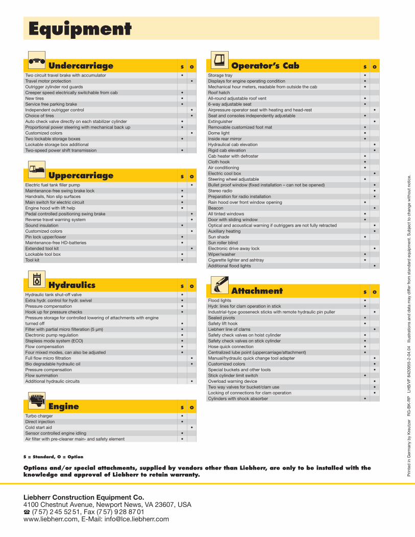
S = Standard, O = Option
Options and/or special attachments, supplied by vendors other than Liebherr, are only to be installed with theknowledge and approval of Liebherr to retain warranty.
Equipment
Undercarriage S O
Two circuit travel brake with accumulator •Travel motor protection •Outrigger zylinder rod guardsCreeper speed electrically switchable from cab •New tires •Service free parking brake •Independent outrigger control •Choice of tires •Auto check valve directly on each stabilizer cylinder •Proportional power steering with mechanical back up •Customized colors •Two lockable storage boxes •Lockable storage box additionalTwo-speed power shift transmission •
Operator’s Cab S O
Storage tray •Displays for engine operating condition •Mechanical hour meters, readable from outside the cab •Roof hatchAll-round adjustable roof vent •6-way adjustable seat •Airpressure operator seat with heating and head-rest •Seat and consoles independently adjustable •Extinguisher •Removable customized foot mat •Dome light •Inside rear mirror •Hydraulical cab elevation •Rigid cab elevation •Cab heater with defroster •Cloth hook •Air conditioning •Electric cool box •Steering wheel adjustable •Bullet proof window (fixed installation – can not be opened) •Stereo radio •Preparation for radio installation •Rain hood over front window opening •Beacon •All tinted windows •Door with sliding window •Optical and acoustical warning if outriggers are not fully retracted •Auxiliary heating •Sun shade •Sun roller blindElectronic drive away lock •Wiper/washer •Cigarette lighter and ashtray •Additional flood lights •
Uppercarriage S O
Electric fuel tank filler pump •Maintenance-free swing brake lock •Handrails, Non slip surfaces •Main switch for electric circuit •Engine hood with lift help •Pedal controlled positioning swing brake •Reverse travel warning system •Sound insulation •Customized colors •Pin lock upper/lower •Maintenance-free HD-batteries •Extended tool kit •Lockable tool box •Tool kit •
Hydraulics S O
Hydraulic tank shut-off valve •Extra hydr. control for hydr. swivel •Pressure compensation •Hook up for pressure checks •Pressure storage for controlled lowering of attachments with engineturned off •Filter with partial micro filteration (5 µm) •Electronic pump regulation •Stepless mode system (ECO) •Flow compensation •Four mixed modes, can also be adjusted •Full flow micro filtration •Bio degradable hydraulic oil •Pressure compensationFlow summationAdditional hydraulic circuits •
Attachment S O
Flood lights •Hydr. lines for clam operation in stick •Industrial-type gooseneck sticks with remote hydraulic pin puller •Sealed pivots •Safety lift hook •Liebherr line of clams •Safety check valves on hoist cylinder •Safety check valves on stick cylinder •Hose quick connection •Centralized lube point (uppercarriage/attachment) •Manual/hydraulic quick change tool adapter •Customized colors •Special buckets and other tools •Stick cylinder limit switch •Overload warning device •Two way valves for bucket/clam use •Locking of connections for clam operation •Cylinders with shock absorber •
Engine S O
Turbo charger •Direct injection •Cold start aid •Sensor controlled engine idling •Air filter with pre-cleaner main- and safety element •


![[ 924 ]users.auth.gr/~adagkas/images/7. 924-939_fotos02.pdf[ 924 ] 98. Ôï êôßñéï ôçò äéáöþôéóçò, óôç MogoÕoaia, 1968 (ðçãÞ: åðéèõìåßôáé ç áíùíõìßá](https://img.pdfslide.net/doc/110x75/60695562ea5e4d462f670c99/-924-usersauthgradagkasimages7-924-939-924-98-.jpg)