Embed Size (px)
Citation preview

Technical Documentation: Fire Detectors used in hazardous areas
P-DET/EX/RCE/PM5/GKa/110995 1 Autronica Fire and Security AS
Technical Documentation
Fire Detectorsused in hazardous areas
Analogue Addressable system type BS-100with zener barrier unit type BZ-32
Conventional system type BX-40with zener barrier type BZ-20S
P-DET/Ex/RCE
Autronica Fire and Security ASN-7483 Trondheim.Phone: +47 73 58 25 00, fax: +47 73 58 25 01
Autronica Industrial Ltd., Watford, EnglandPhone: 1923 23 37 68, fax: 1923 22 55 77.Oil & GAs AS, Stavanger, NorwayPhone: +47 51 84 09 00, fax: +47 51 84 09 49

Technical Documentation: Fire Detectors used in hazardous areas
P-DET/EX/RCE/PM5/GKa/110995 2 Autronica Fire and Security AS
Table of contents:
Abbreviation, related to fire equipment in ex-area 3
1 General part 4
1.1 Danger of explosion 4
The triangle of explosion 5
1.2 Ex-classifications 6
1.3 Labelling electrical equipment 9
1.4 Limiting temperatures 10
1.5 Installing fire alarm equipment in hazardous area 11
1.6 Installation of Autronica fire alarm systems in hazardous areas 11
1.7 Rules regarding potential equalization, PE, to fire detectors
in hazardous areas 13
1.8 Potential equalizations: PE on ships 14
1.9 Installation data - 15
Limitations w.r.t capacitance in cable and detectors/call-points
connected to zener barrier type Z667/Ex
(part of zener barrier BZ-20/S and BZ-32)
2 Analogue addressable system type BS-100 16
2.1 Zener barrier unit type BZ-32 16
2.2 BZ-32, connection diagram, drawing BZ-049 (BZ-047) 17
2.3 BZ-32, functional description, drawing BZ-044 18
3 Conventional system type BX-40 24
3.1 Zener barrier unit type BZ-20/S 24
3.2 BZ-20/S, connection diagram, drawing BZ-076 (BZ-078) 25
3.3 Arranging Ex-loop 25
3.4 BZ-20/S, functional description, drawing BZ-053 25

Technical Documentation: Fire Detectors used in hazardous areas
P-DET/EX/RCE/PM5/GKa/110995 3 Autronica Fire and Security AS
Abbreviation, related to fire alarm equipment in Ex area.
Abbreviation: Explanation.
ANSI : American National Standard Institute.
BASEEFA: British Approvals Service for Electrical Equipmentin Flammable Atmospheres.
CENELEC: European Commitee for Electrotechnical Standardization.
DNV: (Det Norske Verital) Norwegian Approval Institute.
EEx: Explosion protection to European standards.
EN: Norms edited by CENELEC.
FM: Factory Mutual (USA).
IEC: International Electrotechnical Commission
(Prototype for EN-norms).
ESBN: International Standard Book Number.
NEC: National Electrical Code (USA).
NEK: (Norsk Elektroteknisk Komite)
Norwegian Electrotechnical Commitee.
NEMKO: (Norsk Elektrisk Materiellkontroll)
Norwegian Electrical Material Control.
NFPA: National Fire Protection Association (USA).
PA/PE: Equipotential terminal.
PTB: West German Approval Organization
(Physikalisch Technische Bundesanstalt).
VDE: West German Approval Organization
(Verband Deutcher Elektrotechniker).

Technical Documentation: Fire Detectors used in hazardous areas
P-DET/EX/RCE/PM5/GKa/110995 4 Autronica Fire and Security AS
1 General part1.1 Danger of explosion.
An explosion is a very rapid combustion, depending on the access of oxygen.More oxygen accelerate the combustion. Some compounds, such as powderand dynamite, has oxygen "baked" into the substance.
This description is concerning hazardous gases, and different ways of prevent-ing these from exploding.
The emphasis is to prevent electrical energy from getting access to the hazard-ous area in an amount big enough to trigger a fire and consequently anexplosion.
Three ingredients are necessary to perform an explosion. These three ingredi-ents are:Explosive gas, oxygen (air) and igniting energy.
If one of these ingredients is missing, completely or partly, an explosion cannot take place.The curve below shows how these ingredients affect the hazard of explosion.Specially observe that for gas/air mixtures a value exist where minimumigniting energy is necessary for an explosion to take place. Both more and lessconcentrate mixtures will need more igniting energy to get the gas exploding.To strong, and too weak concentrations are not exploding.
123456789012123456789012123456789012123456789012123456789012123456789012123456789012123456789012123456789012123456789012123456789012123456789012123456789012123456789012123456789012123456789012123456789012123456789012123456789012123456789012123456789012123456789012123456789012123456789012123456789012123456789012123456789012123456789012123456789012123456789012123456789012123456789012123456789012123456789012123456789012123456789012123456789012123456789012123456789012123456789012
123456789012345671234567890123456712345678901234567123456789012345671234567890123456712345678901234567123456789012345671234567890123456712345678901234567123456789012345671234567890123456712345678901234567123456789012345671234567890123456712345678901234567123456789012345671234567890123456712345678901234567123456789012345671234567890123456712345678901234567123456789012345671234567890123456712345678901234567123456789012345671234567890123456712345678901234567123456789012345671234567890123456712345678901234567123456789012345671234567890123456712345678901234567123456789012345671234567890123456712345678901234567123456789012345671234567890123456712345678901234567123456789012345671234567890123456712345678901234567123456789012345671234567890123456712345678901234567123456789012345671234567890123456712345678901234567123456789012345671234567890123456712345678901234567123456789012345671234567890123456712345678901234567123456789012345671234567890123456712345678901234567123456789012345671234567890123456712345678901234567123456789012345671234567890123456712345678901234567
Ignitingenergy
Igniting energynecessary forexplosion.
To weakmixture
Too strongmixture
Minimumigniting energy
0 ...............................................% gas.............................................. 100100 ..............................................% Air..................................................0
General part
Danger ofexplosion

Technical Documentation: Fire Detectors used in hazardous areas
P-DET/EX/RCE/PM5/GKa/110995 5 Autronica Fire and Security AS
The triangle of explosion.
oxygen gas
igniting energy
igniting energy
oxygen gas
igniting energy
oxygen gas
igniting energy
oxygen gas
The equilateral, big triangle, may be considered to represent a case withoptimum gas/oxygen relation, i.e. minimum ignition energy is required totrigger an explosion. If the ignition energy is high enough, an explosion willtake place.
The small triangle to the left has the same values of oxygen and ignitingenergy as in the equilateral, big triangle, but the content of gas is too small toperform an explosion.I.e. the gas/air mixture is too weak for an explosion to take place.
The remaining two small triangles should be self-explaining, showing thecases with too low igniting energy and too little oxygen respectively.

Technical Documentation: Fire Detectors used in hazardous areas
P-DET/EX/RCE/PM5/GKa/110995 6 Autronica Fire and Security AS
1.2 Ex-classificationsThe risk of explosion is different for different gas types and areas where the gasis expected to be present. Therefore classifications of gases into Groups andareas into Zones are necessary.
Group classification is concerning the type of gas which is (or is expected tobe) present in the hazardous area. Two criteria are of value when the gas is tobe classified.
a) The gas grade of explosion hazard, andb) The ignition energy necessary to make the gas explode.
Zone classification is, as the name indicates, based upon the zones surroundingthe gas source.
Classifications are indicated by type description. The example below shows thetype:Exib/IIC, which is, by the way, the claims Autronica set to the products used inhazardous areas.
Ex - means that the equipment is intended for use in hazardous area.(EEx is European standard)
i - means that the equipment is intrinsically safe.
b - means that the equipment must be used in zone 1 or 2.(a - is zone 0, 1 and 2)
II - means that the equipment is intended for group II, which coversnearly all purposes. (Group I is Mining Industry, mainly).
C - means that the equipment is build to withstand the most extremeclaims with respect to safety. (Ignition energy less than 20 µ -joule and surface temperature less than 85°C).
The drawing below shows the distribution of zones around gas sources. Theright illustration shows a simple concentric arrangement, while the left oneillustrates a tank under loading or unloading. The expansion of zones 1 and 2along the base is due to the fact that the gas has a higher density than the air.
In most of the industry buildings where danger of explosion exist, the main partof the hazardous area is characterised as Zone 2.
Note that USA and Canada have different zone classification, such that their"Division 1" covers Zone 0 and Zone 1. "Division 2" covers Zone 2.
Ex-classifications

Technical Documentation: Fire Detectors used in hazardous areas
P-DET/EX/RCE/PM5/GKa/110995 7 Autronica Fire and Security AS
The table below shows the different forms of protection against gas explosion,in abbreviations and explanations. The latter is presented in the plain languagesmost used by Autronica personnel, handling fire alarm problems.
Plain language explanation in:
Abbreviation Norwegian English German
Exd Eksplosjonssikker Flame proof Druckfeste Kapselungutførelse
Exe Tennsikker utførelse Increased safety Erhöhte sicherheit
Exm Innstøpt utførelse Moulded Vergusskapselung
Exn Utstyr for sone 2 Equipment forZone 2.
Exs Spesialutførelse Special construction Sonderschutz
Exi Egensikker utførelse Intrinsically safe EigensichereExia Sone 0, 1 og 2 Zone 0, 1 and 2 BetribsmittelExib Sone 1 og 2 Zone 1 and 2
Exp Overtrykkskapsling Pressurized enclosure Überdruckkapselung
Exo Oljefylt Oil immersed Ölkapselung
Exq Sandfylt Sand filled Sandkapselung
Note that all Ex-determinations, except Exi, Exia, and Exib are concerningapparatuses.
Intrinsic safety.(Concerns circuits, which may include several apparatuses).Intrinsically safe equipment has limited supply of electrical energy, so that anyspark created has too low energy to ignite the gas.Also no part of the equipment surface shall be able to reach a temperaturegreater than the igniting temperature of the gas. (Which is, or may be expectedto be present.) In order to be able to perform this energy limitation, energybarriers are necessary to limit the supply of electrical energy to the hazardousarea. Such energy barriers are built up by means of zener diodes, and thereforethey are given the name Zenerbarriers.
Exi-equipments are arranged in two main groups, Group I and Group II.The latter, which is the one being concerned in this description is again dividedin three parts, namely: Group IIA, Group IIB, and Group IIC. (Group I isconcerning Mining Industry, mainly).Equipment may, of course, be used for less hazardous area than what it is builtfor.

Technical Documentation: Fire Detectors used in hazardous areas
P-DET/EX/RCE/PM5/GKa/110995 8 Autronica Fire and Security AS
The table below shows the relation between temperature grades, equipmentsurface temperature, and gas ignition temperature.
Temperature grades T1 T2 T3 T4 T5 T6
Max. surface temperature °C 450 300 200 135 100 85
Gas min. ignition temperature °C 450 300 200 135 100 85
Note that maximum surface temperature must not, at any occasion (even withfault) exceed the igniting temperature of the actual gas.
The table below shows the relationship between different gas groups andallowed igniting energy.
Gas-group IIA IIB IIC
Igniting Energy in µ Joule 200 60 20
NOTE that values given for igniting energy are limits, and therefore safetyfactors must be introduced. Values may be selected from the CENELEC normEN-50020.
In order to calculate igniting energy, the following two equations are actual:
Energy stored in a capacitor (capacitance) is: EC = ½ C U2
Energy stored in a coil (inductance) is: EL = ½ L I2
Where: EC
and EL are energies in Joules.
C is capacitance in Farads.U is voltage in Volts.L is inductance in Henry.I is current in Ampere.
Note that wires represents both capacitance and inductance, and this phenom-ena must be taken into consideration for long wire installations at the hazardousside of zenerbarriers.

Technical Documentation: Fire Detectors used in hazardous areas
P-DET/EX/RCE/PM5/GKa/110995 9 Autronica Fire and Security AS
1.3 Labelling electrical equipmentElectrical equipment intended for use in hazardous area, shall be properlylabelled in accordance with claims brought forward by national or internationalauthorities.
The label shall, according to, e.g. EN-50020, contain the symbol Ex, the formof protection (see table page 7, Abbreviation) e.g. "i", gas group (see tablepage 8) e.g. "IIB", and eventually the class of temperature e.g. "T3". This istrue if the maximum ambient temperature is diverging from + 40°C.
The label also shall show the name or logo of test- and approving institutionand test approval statement.
For small electrical equipment, with limited space, reduced labelling may beaccepted.The label shall then include:The symbol Ex, name of Test institution (test approval), and Manufacturer.
Description: Labelling code:
Approval sign for apparatus certified byan institution within the European CommonMarket, EC: Ex EEx i a/b IIB T3
Sign indicating that the equipment is producedaccording to The European Norm (EN)EEx means: "Explosion protection to
European standards"
Intrinsically safe performance; ia or ib (see page 6)
ia: withstands 2 faults with safety factor = 1or 1 fault with safety factor = 1,5
ib: withstands 1 fault with safety factor = 1,5or 1 fault with safety factor = 1and no unprotected conductor
Group: IIA, IIB or IIC (see page 8)
Temperature class: T1, T2, T3, T4, T5 or T6(see page 8)
This example is made according to theCENELEC norm.

Technical Documentation: Fire Detectors used in hazardous areas
P-DET/EX/RCE/PM5/GKa/110995 10 Autronica Fire and Security AS
1.4 Limiting temperaturesThe table shows limiting temperatures for electrical equipment which may bemounted in hazardous area, according to regulations made by IEC, VDE andNEC.The temperature limits are valid for parts of the equipment, and for everypossible condition.
Classification Classification Classificationaccording to: according to: according to:IEC/CENELEC VDE 170/0171/2.61 NEC(USA/Canada)
Ignitingtemperature Temp. Temp. Igniting Max. Max. Temp. Gasfor gases class limit group temp. temp. identi- igniting
°C °C °C °C fication temp.Contin- Shortously term
450 T1 450 G1 T1 450
300 T2 300 360 400 T2 300
T2A 280
G2 270 T2B 260
240 T2C 230
T2D 215
200 T3 200 T3 200
180 T3A 180
G3 T3B 165
160 T3C 160
135 T4 135 T4 135
G4 125 T4A 120
110
100 T5 100 G5 90 T5 100
85 T6 85 80 T6 85
Technical Documentation: Fire Detectors used in hazardous areas
P-DET/EX/RCE/PM5/GKa/110995 11 Autronica Fire and Security AS
1.5 Installation fire alarm equipment in hazardous area.This description can not, of course, include every possible installation ofelectrical equipment in hazardous area.
Therefore, the most common rules are mentioned below:
In power distribution systems with earthed zero terminal, the earth wire and thezero terminal shall be kept insulated inside hazardous area. A common earth-and zero wire (PEN-wire) is not allowed.
Comment:Common earth- and zero-wire (PEN-wire) may be utilized for that part of thedistribution network outside the hazardous area.
Distribution systems with insulated zero wire must have an earth fault operatingswitch breaking the circuit at a current of 500 mA, or have facility which byaudible or visible signal gives warning of earth fault in the system.When an earth fault is given, the fault must be repaired immediately.
Earth wire must physically be situated in the same tube as the feeding wires.(Separate earth wires are not accepted.)
Comment:The claims do not exclude use of separate earth wire as equipotential connec-tion in addition to common safety earth wire. Such equipotential connectionought to be used for special exposed system parts, e.g. construction elements ofelectrically conducting material, pipes etc. in order to avoid potential differenceand consequently danger of electrostatic charges.
In addition to the comments above, it must be mentioned that the termequipotential connection is differently abbreviated in different documents, suchthat PA-, PE-, a.o.
In this document the term PE- is preferred.
1.6 Installation of Autronica fire alarm systems inhazardous areas.
Several approval authorities have more or less equal norms to be the recom-mending and normgiving authorities respectively. But we must recommend youto obtain the laws and regulations concerning your country, because slightlydifferent rules exists in different countries.
Installation firealarm equipmentin hazardous area
Installation ofAutronica
fire alarm inhazardous area

Technical Documentation: Fire Detectors used in hazardous areas
P-DET/EX/RCE/PM5/GKa/110995 12 Autronica Fire and Security AS
In this description the part regarding installation will be confined to our zenerbarrier unit type BZ-32, mainly. This unit is built up by means of AC-zenerbarrier as main component. The advantage of using this ac-barrier is explainedby the two sketches, and the associated description below:
R1 R2
Z1 Z2
Z3 Z4
R3 R4
Positivebarrier
Negativebarrier
F1
F2
PE RS
13
4
23
11
2
21
Resistor
R1
Resistor
R2
Fuse
F1
Fuse
F2
ZD1 ZD2 ZD3
ZD7 ZD8 ZD9
ZD4 ZD5 ZD6Zener diodes
Zener diodes
Fig. 1 Fig. 2
Diagram fig.1 shows the connection of two zener barriers, one positive and onenegative, confining one zener barrier unit. This unit has been used for our firealarm detector lines (loops).
With no fault the arrangement is perfect, without any trouble. The PE- terminalwill then, electrically viewed, be situated midway between minus (-) and plus(+), at the same potential as the earth terminal in the panel, approximately. ThePE-terminal and the panel's earth terminal must be connected together (outsidethe hazardous area), and therefore an earth indication will be given by thepanel, if the PE-terminal is connected to minus (or plus). When the detector lineis disconnected by shorting the plus- and minus-wires (as in the BS-systems)trouble will be introduced because then the zener barrier Z1 and Z2 willconnect the PE-terminal to minus.
Considering the same situation with ac-barriers (see fig. 2), it is easily shownthat the zener diodes ZD7, ZD8 and ZD9 will prevent the PE-terminal frombeing connected to minus.
Data for zener barrier type Z667/Ex
Nominal Type Max. end to end Working voltage Max. voltage FuseCharact- no. resistance at 10mA leakage ratingeristics mA
18V 120W Z667/Ex 135.4W 14.5V 16.5V 5018V 120W 135.4W 14.5V 16.5V 50
Zener barrier type Z667/Ex
RS
PE

Technical Documentation: Fire Detectors used in hazardous areas
P-DET/EX/RCE/PM5/GKa/110995 13 Autronica Fire and Security AS
Rules regardingpotential
equalization, PE,to fire detectors inhazardous areas
1.7 Rules regarding potential equalization, PE, to firedetectors in hazardous areas.
To avoid sparks between an intrinsically safe circuit and the surroundings theuse of a Potential Equalization is required. Normally this is done by a PE-conductor grounded at the zener barrier.
We differ between insulated detectors (plastic housing) and detectors inconducting metal housing.
Detectors in plastic housing are non-conducting.
We also differ between conducting and non-conducting surface for mounting.
For insulated detectors the following applies:The PE-conductor shall only pass through.Some detectors and junction boxes have separate, insulated terminals for thePE-conductor. Some detectors have no special terminal for the purpose, and theconnections for continuity must be provided by the installer.This applies when mounted on both conducting and non-conducting surface.
For detectors in conducting metal housings the following applies:
When mounted on non-conducting surface , e.g. concrete the PE-conductorshall be connected to the inside of the housing.Special terminal screws are provided.
When mounted on conducting surface, the PE-conductor shall be connectedto the inside of the housing.The outside earth terminal screw shall be connected to the surface.
A special case is when mounted in all welded steel ships. According toclassification societies (e.g. Det Norske Veritas) the hull itself can beregarded as a PE-conductor, and PE-cabelling can be omitted.Detectors in conducting metal housings must have good connection to the hull.
If a screened cable is used, the screen can not be used as a PE-conductor.The screen shall continously pass through all detectors and shall begrounded at the zener barrier only.
Earthing of the zenerbarriere:
Onboard ships:
The earth terminal of the zener barrier unit shall be connected to earth(ships hull) by a cable not less than 4mm2.
The cable resistance must not exceed 1 Ω.
Onshore:
As there are different regulations for different countries you should check thelocal regulations.An extract from BS5345 pt. 4 is printed here as an example:
"....to preserve the integrity of an intrinsically safe system (e.g. a diode safetybarrier earth, a transformer screen earth, a barrier relay frame earth) suchconnections should be made to a high integrity earth in such a way as to ensurethat the impedance from the point of connection to the main power system earthpoint is less than 1 Ω. This may be achieved by connection to a switch room orsimular earth bar or by the use of separate earth rods. The conductor used forthe connection should be equivalent to a copper conductor of 4 mm2 minimumcross-sectional area.
"The conductor used for the earth connection should be insulated to preventinvasion of the earth by fault currents which might flow in metallic parts withwhich the conductor should otherwise come into contact (e.g. control panelframes etc.). It should also be given mechanical protection in places where therisk of damage is high."

Technical Documentation: Fire Detectors used in hazardous areas
P-DET/EX/RCE/PM5/GKa/110995 14 Autronica Fire and Security AS
1.8 Potential equalizations: PE on ships.
A: Insulated sensor on non conducting wall:PE-conductor only passing through.
B: Insulated sensor on conducting wall:PE-conductor only passing through.
C: Metal sensor on conducting wall:PE-conductor connected to inside of box. Outside earth screwconnected to wall.
D: Metal sensor on non conducting wall:PE-conductor connected to box.
For an intrinsically safe circuit the main demands are:
1: Voltage, current and energy has to be below certain values (depending ongas types), so that any sparks due to shortening or breaking the circuit donot ignite the gas mixture.
This may be achieved by the use of a Zener barrier and restrictions forinductively and capacity.
2: To avoid sparks between the IS circuit and the surrounding the use of aPotential Equalization is necessary.
Normally this is done by a PE-conductor, grounded at the zener barrier.When disconnected it shall withstand 500 V to ground. In welded steelships however, according to "Det Norske Veritas", the hull itself may beused as potential equalization conductor.
3: The temperature of any component in an IS-circuit shall be below a givenvalue, depending on the gas group.
PE
+
-
+
PE
-
Zenerbarrier A B C D
Conducting wall etc.

Technical Documentation: Fire Detectors used in hazardous areas
P-DET/EX/RCE/PM5/GKa/110995 15 Autronica Fire and Security AS
1.9 INSTALLATION DATA
Limitations w.r.t. capacitance in cable and detectors/call-points connected to zenerbarrier type Z667/Ex (part of zener barrier units BZ-20/S and BZ-32).
For an intrinsically safe circuit connected to a zener barrier, there is a limitation as to how large a capacitance(C
max) the circuit can hold. C
max will vary depending on which gas group is present in the area where there is a
danger from explosion.
For zener barrier Z667/Ex, the values are:for gas group IIC : C
max = 0.440 µF
for gas group IIB : Cmax
= 1.32 µFfor gas group IIA : C
max = 3.52 µF
The following parameters apply:The total capacitance in the cable and detectors/call-points shall not exceed C
max.
Max. number of units connected to each zenerbarrier in BZ-20 and BZ-32 is 10. The total capacitance ineach branch must not exceed C
max.
Cable: Capacitance in cable varies with type, but if the value is unknown, use a value of 200 pF permetre as maximum.
Detectors: Equivalent capacitance (Ci /C
eq) is for different detectors/call-points, as set during testing/certifica-
tion by NEMKO.Group IIA Group IIB Group IIC
BD-26/Ex: Ci = 36 nF
BD-27/Ex: Ci = 36 nF 10 10 10
BE-30/Ex: Ci = 80 nF 10 10 5
BE-34/Ex: Ci = 80 nF
BH-31A/Ex: Ci = 30 nF 10 10 10
BH-31A/S/Ex: Ci = 30 nF
BJ-20B/Ex: Ceq
≤ 0,2 µF 10 6 2BJ-31/Ex: C
eq ≤ 0,2 µF
BF-35/Ex: Ceq
≤ 10 nFBF-32M/Ex C
eq ≤ 10 nF 10 10 10
BF-52/Ex: Ceq
≤ 10 nFBF-53/Ex: C
eq ≤ 10 nF
BF-33/Ex: Ceq
≤ 0,4 µF 8 3 1BF-34/Ex: C
eq ≤ 0,4 µF
BN-35/Ex: Ceq
≤ 10 nF 10 10 10BN-32M/Ex: C
eq ≤ 10 nF
The number of detectors / call-points is calculated with a cable of 200 m (200 m x 200 pF).Notes: 1 µF = 1.000 nF = 1.000.000 pF
E.g. for gas group IIC (Cmax
= 0.440 µF) for a single zener barrier type Z667/Ex.50 m cable (à 200 pF) = 10 nF2 x BF-35/Ex (à 10 nF) = 20 nF7 x BH-31A/Ex (à 30 nF) = 210 nF1 x BJ-31/Ex (à 0.2 µF) = 200 nF
440 nF = 0.440 µF

Technical Documentation: Fire Detectors used in hazardous areas
P-DET/EX/RCE/PM5/GKa/110995 16 Autronica Fire and Security AS
2 Analogue addressable system type BS-100
2.1 Zener barrier unit type BZ-32Barrier unit BZ-32 is mainly intended to be used together with Autronicaaddressable fire alarm systems. The main component is one ac-barrier (see page12) for each branch for connection of detectors in hazardous area.
Each unit may contain from one to four ac-barriers, and may consequently beloaded with the same numbers of branches as the unit contains ac-barriers.Each branch may take up to ten addresses.
The type indication includes the number of acceptable branches, indicated by adigit placed behind a diagonal at end of type indication.
E.g. BZ-32/3 means that the maximum number of branches which may beconnected to this unit is 3.
Do remember that the total numbers of addresses at one BS-loop must belimited to 99.
Note!Units listed below only, may be connected to the zener barrier unit type BZ-32/n (n being any number from 1 to 4).
Smoke detector, optical type BH-31A/Ex and BH-31A/S/ExSmoke detector, ion-chamber type BJ-33/Ex (BJ-31/Ex)
Heat detector type BE-30/ExHeat detector type BE-34/Ex
Manual Call-point type BF-32M/ExManual Call-point type BF-33/ExManual Call-point type BF-34/ExManual Call-point type BF-35/Ex
Interface unit type BN-35/Ex to whichheat detector type BD-26/Ex (BE-26/Ex) andheat detector type BD-27/Ex (BE-27/Ex may be connected.
BD-26/Ex (BE-26/Ex) and BD-27/Ex (BE-27/Ex) are conventional heatdetectors.
In order to limit the current consumption, none of these units are equipped withalarm indicator (LED).
The four first mentioned detectors may, as described above, be connected toone branch in number of maximum 10 units. 1)
BN-35/Ex or BF-35/Ex must have the highest address numbers on thebranch.
1) This is purely estimated from an electrotechnical point of view. Other criteriasto be estimated are gas group and total capacitance, C
eq.
See page 15.
Analogueaddressable
system BS-100
Zener barrierunit type BZ-32

Technical Documentation: Fire Detectors used in hazardous areas
P-DET/EX/RCE/PM5/GKa/110995 17 Autronica Fire and Security AS
2.2 BZ-32, connection diagram, drawing BZ-049A (BZ-047A)
The diagram is separated in two main parts by a dot-dash-line. The componentslocated above that line is mounted in the hazardous area, and must be approvedfor that purpose. At the projecting period it is important to place as little aspossible of the total equipment in the hazardous area.
Detectors which are operating independent of interface unit type BN-35/Exand are equipped with separate addresses, are marked with capital "D".
Conventional detectors, which need interface unit BN-35/Ex, are marked withsmall "d" and all these detectors will have the same address number.
Note that, of course, all detectors must be approved for mounting insidehazardous area, i.a. being marked B--/Ex.
Note also that the address number of BNB-35/Ex is given (n + 1) because thisunit (or BF-35/Ex) must be given the highest number of that branch.
Units loaded below the dot-dash-line are common Autronica fire alarm equip-ments. The equipotential line is marked with PE and is connected to terminalmarked 4 on the zener barrier unit.
Note that the equipotential terminal, (marked 4 on the ac-barrier unit) must notbe connected to the system earth inside hazardous area. These two terminalsare, however, shorted inside the ac-barrier unit itself.
On branch no. 1 an interface unit type BNB-35/Ex is shown in detail for boththe input terminals "1 + 2" and "3 - 4", and the sub-loop, SL's connection toterminals 5(-) and 6(+).The sub-unit BNB-35/Ex is used for call-point BF-35/Ex and interface unitBN-35/Ex which is the one shown on this drawing.The manual call-point, BF-35/EX, has no possibility for sub-loop connection.(The terminals 5 and 6 are used for the push-button, which is to be manuallyoperated.)
(The highest address number, which on the drawing BZ-049A is given to ananalogue addressable detector is "n", and unit BNB-35/Ex is given the addressnumber "n + 1")
Also remember that here must the equation; n ≤ 9 be satisfied.
Zener barrier unit type BZ-32/1 contains 1 unit type Z-667/ExZener barrier unit type BZ-32/2 contains 2 units type Z-667/ExZener barrier unit type BZ-32/3 contains 3 units type Z-667/ExZener barrier unit type BZ-32/4 contains 4 units type Z-667/Ex
BZ-32,connection
diagram

Technical Documentation: Fire Detectors used in hazardous areas
P-DET/EX/RCE/PM5/GKa/110995 18 Autronica Fire and Security AS
2.3 BZ-32 functional description, drawing BZ-044CThis diagram shows, in detail, how the current flow in the hazardous area islimited to an acceptable value. On page 12 you will find diagram and descrip-tion of the barrier Z-667/Ex where the detector line (loop) is represented by aresistor "R
S".
The potential equalization terminal is, inside the barrier Z-667/Ex, shorted tothe system "earth".
Only one of the four possible branches is illustrated. The other branches, (1 to3) would have been drawn in an equal manner. The following functionaldescription is referring to branch number one.
The current through the branch is fed from plus (1 + 2), through the emitter -base resistor R
1, through the barrier Z-667/Ex terminals 21 to 23, through the
detectors "D" (which are parallel connected in a numbers of 1 to 10), throughthe barrier Z-667/Ex terminals 13 to 11, and from there to minus (3 - 4).
The emitter - base resistor R1 is given a value to obtain a suitable voltage drop
so the transistor V1 does not conduct if none of the detectors is conducting.
The signal answer current, caused by any of the detectors, will increase thevoltage drop across R
1, causing transistor V
1 to conduct, passing a much greater
current through resistor R2. This causes the greater part of the signal current to
pass through the transistor and it's collector resistor R2.
In this way the necessary signal current through any of the detectors is limitedto a value which is acceptable for consumption inside the hazardous area.(Accepted by the zener barrier's internal resistance.
All (maximum 4) branches are functioning in the same way, and perform signalon the same terminal bloc, X1.
Observe that each detector; D1, D
2 etc. to D
n are individually addressed.
BZ-32function
description

Technical Docum
entation:Fire D
etectors used in hazardous areas
P-D
ET
/EX
/RC
E/P
M5/G
Ka/110995
19A
utronica Fire and S
ecurity AS
BZ
-056C
DIMENTIONAL SKETCHZENER BARRIER UNIT TYPE BZ-32/1-4UNIT MAY BE MOUNTED IN ANY ORIENTATION.
Merk: Festehull for boks til vegg, og lokk til boks er konsentriske.For å beholde beskyttelsesgrad, IP55.
Note: In order to maintain encapsulation rating, IP55, mountingholes for box to wall are concentric to the lid's fixing holes.
SAFE AREA & HAZARDOUS AREA CABLES MUST BESEPARATED BY MIN. 50mm INSIDE AND OUTSIDE OF THEHOUSING.
SAFE AREACONNECTIONS ONLY.
HAZARDOUS AREACONNECTIONS ONLY.

Technical Documentation: Fire Detectors used in hazardous areas
P-DET/EX/RCE/PM5/GKa/110995 20 Autronica Fire and Security AS
BZ-044C
FUNCTIONAL DIAGRAMZENER BARRIER UNITTYPE BZ-32/1-4

Technical Documentation: Fire Detectors used in hazardous areas
P-DET/EX/RCE/PM5/GKa/110995 21 Autronica Fire and Security AS
BZ-047A
CONNECTION DIAGRAMZENER BARRIER UNITTYPE BZ-32/1
Max 1Ω

Technical Documentation: Fire Detectors used in hazardous areas
P-DET/EX/RCE/PM5/GKa/110995 22 Autronica Fire and Security AS
BZ-049A
CONNECTION DIAGRAMZENER BARRIER UNITTYPE BZ-32/1-4
Max 1Ω

Technical Documentation: Fire Detectors used in hazardous areas
P-DET/EX/RCE/PM5/GKa/110995 23 Autronica Fire and Security AS
MA
N.
CA
LL P
. B
F-3
2/E
x(N
ON
IN
SU
LAT
ED
UN
ITS
)IN
TE
RFA
CE
UN
IT B
N-3
5/E
x(I
NS
ULA
TE
D U
NIT
S)
SU
B L
OO
P
HE
AT
ET
EC
TO
RB
D-2
6/E
x O
RB
D-2
7/E
x(I
NS
ULA
TE
D U
NIT
S)
MA
N.
CA
LL P
. B
F-3
5/E
x(I
NS
ULA
TE
D U
NIT
S)
NO
N I
NS
ULA
TE
D U
NIT
S (
ME
TAL
HO
US
ING
)S
HA
LL B
E C
ON
NE
CT
ED
TO
TH
E H
ULL
.
SM
OK
E D
ET
EC
TO
R B
J-31
/Ex
SM
OK
E D
ET
EC
TO
R B
H-3
1/E
x
HE
AT
DE
TE
CT
OR
BE
-30/
Ex
(IN
SU
LAT
ED
UN
ITS
)

Technical Documentation: Fire Detectors used in hazardous areas
P-DET/EX/RCE/PM5/GKa/110995 24 Autronica Fire and Security AS
3 Conventional system type BX-40
3.1 Zener barrier unit type BZ-20/SBarrier unit BZ-20/S is mainly intended to be used together with Autronicaconventional fire alarm systems. The main component is one ac-barrier (seepage 12) for each branch for connection of detectors in hazardous area.
Each unit may contain one or two ac-barriers, and may consequently be loadedwith the same number of loops as the unit contains ac-barriers.Each loop may take up to ten detectors.
The type indication includes the number of acceptable branches, indicated by adigit placed behind a diagonal at end of the indication.
E.g. BZ-20/2S means that the maximum number of loops which may beconnected to this unit is 2.
Note!Units listed below only, may be connected to the zener barrier unit typeBZ-20/nS. (n being the number 1 or 2).
Smoke detector, ion-chamber type BJ-20B/Ex
Heat detector type BE-26M/ExHeat detector type BE-27M/Ex
Manual call-point type BF-21M/Ex
Heat detector type BD-26/Ex (BE-26/Ex)Heat detector type BD-27/Ex (BE-27/Ex)
The detectors may, as described above, be connected to one loop in number ofmaximum 10 units. 1)
1) This is purely estimated from an electro-technical point of view. Othercriterias to be estimated are gas and total capacitance, C
eq.
Conventionalsystem type
BX-40
Zener barrierunit type BZ-20/S

Technical Documentation: Fire Detectors used in hazardous areas
P-DET/EX/RCE/PM5/GKa/110995 25 Autronica Fire and Security AS
3.2 BZ-20/S, connection diagram, draw. BZ-076 (BZ-078)The diagram is separated in two main parts by a dot-dash-line. The componentslocated above that line is mounted in the hazardous area, and must be approvedfor the purpose.At he projecting period it is important to place as little as possible of the totalequipment in the hazardous area.
Note that, of course, all detectors must be approved for mounting insidehazardous area, i.e. being marked B--/Ex.
Units located below the dot-dash-line are common Autronica fire alarmequipments. The equipotential line is marked with PE and is connected toterminal marked 4 on the zener barrier unit.
Note that the equipotential terminal, (marked 4 on the ac-barrier unit) must notbe connected to the system earth inside hazardous area. These two terminalsare, however, shorted inside the ac-barrier unit itself.
Zener barrier unit type BZ-20/1/S contains 1 unit type Z-667/ExZener barrier unit type BZ-20/2/S contains 2 units type Z-667/Ex
3.3 Arranging Ex-loopOne zener barrier for each detector loop in central unit.If none Ex-detector are mixed with Ex-detectors in the same loop, the Ex-detector with it's zener barrier must be the very last element at the loop.
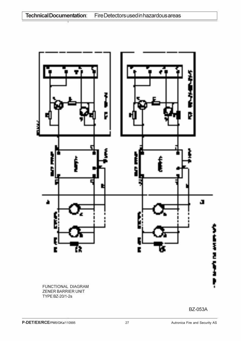
3.4 BZ-20/S, functional description, drawing BZ-053.From the diagram containing PCB BZA-20/S, it is seen that the terminals B andB' are shorted on terminal strip X1.
The resistors R2 have values which make transistor V
1 normally non-conduct-
ing . The control (base) current for these transistors passes through the detec-tors (in parallel, also with the end load) via the zener barrier unit.
Monitoring of the loop is obtained by connecting end load BXY-40/Ex to thelast detector.
Fire alarm given by one of the detectors will cause a rise of the transistors basecurrent. V
1 will be conducting, causing a much greater current to flow through
R1. This latter current indicates fire alarm on the central panel.
BZ-20/SConnection
diagram
ArrangingEX-loop
BZ-20/SFunction
description

Technical Docum
entation:Fire D
etectors used in hazardous areas
P-D
ET
/EX
/RC
E/P
M5/G
Ka/110995
26A
utronica Fire and S
ecurity AS
BZ
-056C
DIMENTIONAL SKETCHZENER BARRIER UNIT TYPE BZ-32/1-4UNIT MAY BE MOUNTED IN ANY ORIENTATION.
SAFE AREACONNECTIONS ONLY.
Note: In order to maintain encapsulation rating, IP55, mountingholes for box to wall are concentric to the lid's fixing holes.
SAFE AREA & HAZARDOUS AREA CABLES MUST BESEPARATED BY MIN. 50mm INSIDE AND OUTSIDE OF THEHOUSING.
HAZARDOUS AREACONNECTIONS ONLY.
Technical Documentation: Fire Detectors used in hazardous areas
P-DET/EX/RCE/PM5/GKa/110995 27 Autronica Fire and Security AS
BZ-053A
FUNCTIONAL DIAGRAMZENER BARRIER UNITTYPE BZ-20/1-2s

Technical Documentation: Fire Detectors used in hazardous areas
P-DET/EX/RCE/PM5/GKa/110995 28 Autronica Fire and Security AS
BZ-078
CONNECTION DIAGRAMZENER BARRIER UNITTYPE BZ-20/1S
Max 1W
1 - 6

Technical Documentation: Fire Detectors used in hazardous areas
P-DET/EX/RCE/PM5/GKa/110995 29 Autronica Fire and Security AS
BZ-076A
CONNECTION DIAGRAMZENER BARRIER UNITTYPE BZ-20/2S
1 - 6
Max 1W

Technical Documentation: Fire Detectors used in hazardous areas
P-DET/EX/RCE/PM5/GKa/110995 30 Autronica Fire and Security AS
ZE
NE
R B
AR
RIE
RU
NIT
S B
Z-2
0/S
HE
AT
DE
TE
CT
OR
BD
-26/
Ex
BD
-27/
Ex
(IN
SU
LAT
ED
UN
ITS
)
MA
N C
ALL
P.
BF
-21M
/Ex
(NO
N I
NS
ULA
TE
D U
NIT
S)
NO
N I
NS
ULA
TE
D U
NIT
S (
ME
TAL
HO
US
ING
)S
HA
LL B
E C
ON
NE
CT
ED
TO
TH
E H
ULL
.
. CO
NN
EC
TIO
N D
IAG
RA
M F
OR
FIR
E D
ET
EC
TO
RS
IN
HA
ZA
RD
OU
S A
RE
A (
Ex)
FO
R I
NS
TALL
AT
ION
IN
ST
EE
LS
HIP
S.
CO
NV
EN
TIO
NA
L S
YS
TE
M.
A-
B-