Embed Size (px)
Citation preview
TechnicalDocumentation
Microphone Type 4964for Hand-held Analyzer Types 2250, 2250-L and 2270
Supplement to Instruction Manual BE 1712
HEADQUARTERS: Brüel & Kjær Sound & Vibration Measurement A/S · DK-2850 Nærum · DenmarkTelephone: +45 7741 2000 · Fax: +45 4580 1405 · www.bksv.com · [email protected]
Local representatives and service organisations worldwide
ËBE-1748---JÎ
English BE 1864 – 11

BE 186411 December 2013
Microphone Type 4964for Hand-held Analyzer
Types 2250, 2250-L and 2270
Type 2250, from Hardware Version 1.1Type 2250-L, from Hardware Version 2.0Type 2270, from Hardware Version 3.0
Supplement to Instruction Manual BE 1712
Copyright 2006 – 2013, Brüel & Kjær Sound & Vibration Measurement A/S
All rights reserved. No part of this publication may be reproduced or distributed in any form, or by any means,without prior written consent from Brüel & Kjær Sound & Vibration Measurement A/S, Nærum, Denmark.
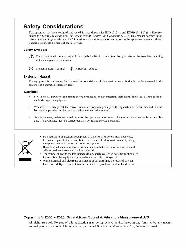
Safety ConsiderationsThis apparatus has been designed and tested in accordance with IEC 61010 – 1 and EN 61010 – 1 Safety Require-ments for Electrical Equipment for Measurement, Control and Laboratory Use. This manual contains infor-mation and warnings which must be followed to ensure safe operation and to retain the apparatus in safe condition.Special note should be made of the following:
Safety Symbols
The apparatus will be marked with this symbol when it is important that you refer to the associated warningstatements given in the manual.
Protective Earth Terminal Hazardous Voltage
Explosion Hazard
The equipment is not designed to be used in potentially explosive environments. It should not be operated in thepresence of flammable liquids or gases.
Warnings
• Switch off all power to equipment before connecting or disconnecting their digital interface. Failure to do socould damage the equipment.
• Whenever it is likely that the correct function or operating safety of the apparatus has been impaired, it mustbe made inoperative and be secured against unintended operation.
• Any adjustment, maintenance and repair of the open apparatus under voltage must be avoided as far as possibleand, if unavoidable, must be carried out only by trained service personnel.
• Do not dispose of electronic equipment or batteries as unsorted municipal waste• It is your responsibility to contribute to a clean and healthy environment by using
the appropriate local return and collection systems• Hazardous substances in electronic equipment or batteries may have detrimental
effects on the environment and human health• The symbol shown to the left indicates that separate collection systems must be used
for any discarded equipment or batteries marked with that symbol• Waste electrical and electronic equipment or batteries may be returned to your
local Brüel & Kjær representative or to Brüel & Kjær Headquarters for disposal
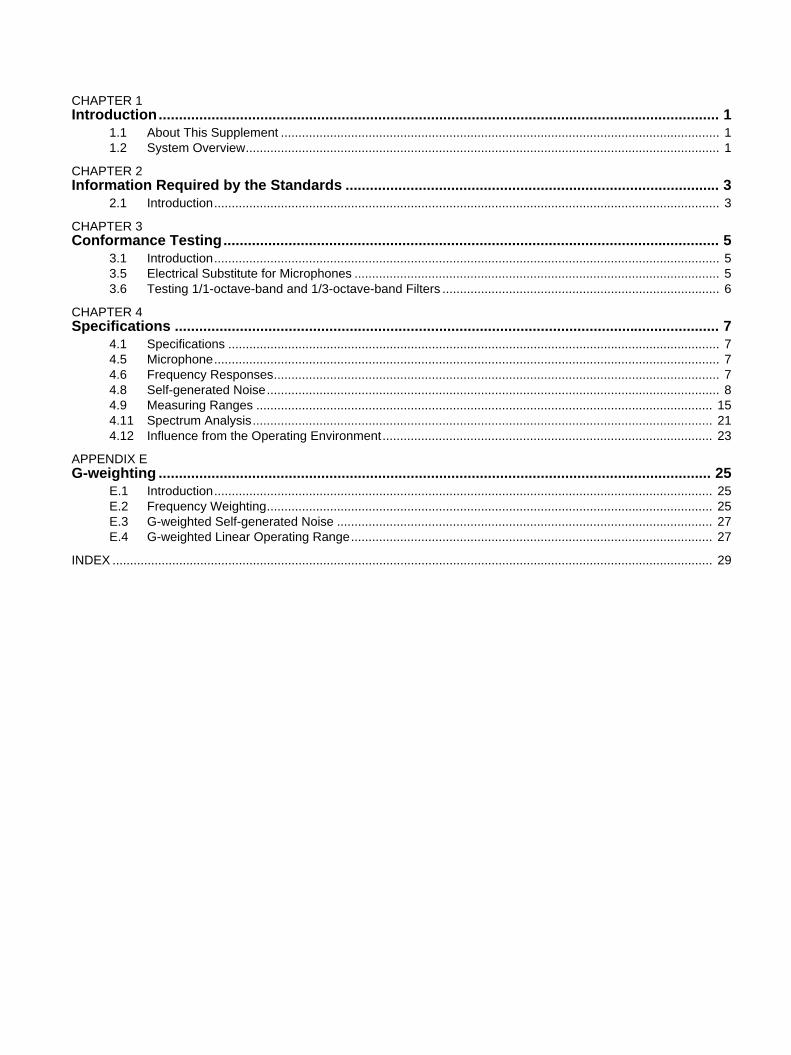
CHAPTER 1Introduction.......................................................................................................................................... 1
1.1 About This Supplement ............................................................................................................................. 11.2 System Overview....................................................................................................................................... 1
CHAPTER 2Information Required by the Standards ............................................................................................ 3
2.1 Introduction................................................................................................................................................ 3
CHAPTER 3Conformance Testing.......................................................................................................................... 5
3.1 Introduction................................................................................................................................................ 53.5 Electrical Substitute for Microphones ........................................................................................................ 53.6 Testing 1/1-octave-band and 1/3-octave-band Filters ............................................................................... 6
CHAPTER 4Specifications ...................................................................................................................................... 7
4.1 Specifications ............................................................................................................................................ 74.5 Microphone................................................................................................................................................ 74.6 Frequency Responses............................................................................................................................... 74.8 Self-generated Noise................................................................................................................................. 84.9 Measuring Ranges .................................................................................................................................. 154.11 Spectrum Analysis................................................................................................................................... 214.12 Influence from the Operating Environment.............................................................................................. 23
APPENDIX EG-weighting ........................................................................................................................................ 25
E.1 Introduction.............................................................................................................................................. 25E.2 Frequency Weighting............................................................................................................................... 25E.3 G-weighted Self-generated Noise ........................................................................................................... 27E.4 G-weighted Linear Operating Range....................................................................................................... 27
INDEX ........................................................................................................................................................................... 29

1
Chapter 1Introduction
1.1 About This Supplement
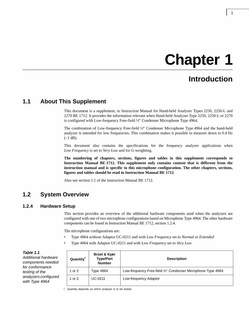
This document is a supplement, to Instruction Manual for Hand-held Analyzer Types 2250, 2250-L and2270 BE 1712. It provides the information relevant when Hand-held Analyzer Type 2250, 2250-L or 2270is configured with Low-frequency Free-field ½ Condenser Microphone Type 4964.
The combination of Low-frequency Free-field ½ Condenser Microphone Type 4964 and the hand-heldanalyzer is intended for low frequencies. This combination makes it possible to measure down to 0.4 Hz(–1 dB).
This document also contains the specifications for the frequency analyzer applications whenLow Frequency is set to Very Low and for G-weighting.
The numbering of chapters, sections, figures and tables in this supplement corresponds toInstruction Manual BE 1712. This supplement only contains content that is different from theinstruction manual and is specific to this microphone configuration. The other chapters, sections,figures and tables should be read in Instruction Manual BE 1712.
Also see section 1.1 of the Instruction Manual BE 1712.
1.2 System Overview
1.2.4 Hardware Setup
This section provides an overview of the additional hardware components used when the analyzers areconfigured with one of two microphone configurations based on Microphone Type 4964. The other hardwarecomponents can be found in Instruction Manual BE 1712, section 1.2.4.
The microphone configurations are:
• Type 4964 without Adaptor UC-0211 and with Low Frequency set to Normal or Extended
• Type 4964 with Adaptor UC-0211 and with Low Frequency set to Very Low
Table 1.1Additional hardware components needed for conformance testing of the analyzers configured with Type 4964
Quantity*Brüel & Kjær
Type/Part Number
Description
1 or 2 Type 4964 Low-frequency Free-field ½ Condenser Microphone Type 4964
1 or 2 UC-0211 Low-frequency Adaptor
*. Quantity depends on which analyzer is to be tested.

Microphone Type 4964 – Supplement to Instruction Manual BE 17122
3
Chapter 2Information Required by the Standards
2.1 Introduction
This chapter contains detailed information required by the standards to be described in the Instruction Manual.
No additional information is required in Chapter 2 when using Microphone Type 4964 togetherwith the analyzer.

Microphone Type 4964 – Supplement to Instruction Manual BE 17124
5
Chapter 3Conformance Testing
3.1 Introduction
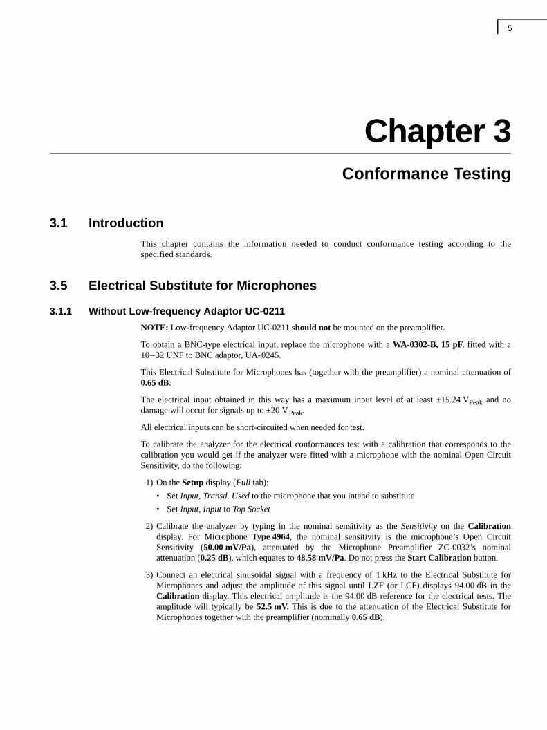
This chapter contains the information needed to conduct conformance testing according to thespecified standards.
3.5 Electrical Substitute for Microphones
3.1.1 Without Low-frequency Adaptor UC-0211
NOTE: Low-frequency Adaptor UC-0211 should not be mounted on the preamplifier.
To obtain a BNC-type electrical input, replace the microphone with a WA-0302-B, 15 pF, fitted with a10–32 UNF to BNC adaptor, UA-0245.
This Electrical Substitute for Microphones has (together with the preamplifier) a nominal attenuation of0.65 dB.
The electrical input obtained in this way has a maximum input level of at least ±15.24 VPeak and nodamage will occur for signals up to ±20 VPeak.
All electrical inputs can be short-circuited when needed for test.
To calibrate the analyzer for the electrical conformances test with a calibration that corresponds to thecalibration you would get if the analyzer were fitted with a microphone with the nominal Open CircuitSensitivity, do the following:
1) On the Setup display (Full tab):
• Set Input, Transd. Used to the microphone that you intend to substitute
• Set Input, Input to Top Socket
2) Calibrate the analyzer by typing in the nominal sensitivity as the Sensitivity on the Calibrationdisplay. For Microphone Type 4964, the nominal sensitivity is the microphone’s Open CircuitSensitivity (50.00 mV/Pa), attenuated by the Microphone Preamplifier ZC-0032’s nominalattenuation (0.25 dB), which equates to 48.58 mV/Pa. Do not press the Start Calibration button.
3) Connect an electrical sinusoidal signal with a frequency of 1 kHz to the Electrical Substitute forMicrophones and adjust the amplitude of this signal until LZF (or LCF) displays 94.00 dB in theCalibration display. This electrical amplitude is the 94.00 dB reference for the electrical tests. Theamplitude will typically be 52.5 mV. This is due to the attenuation of the Electrical Substitute forMicrophones together with the preamplifier (nominally 0.65 dB).
Microphone Type 4964 – Supplement to Instruction Manual BE 17126
3.1.2 With Low-frequency Adaptor UC-0211
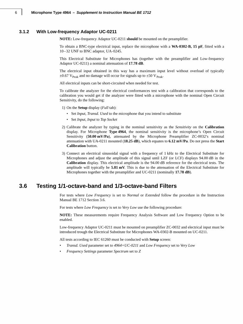
NOTE: Low-frequency Adaptor UC-0211 should be mounted on the preamplifier.
To obtain a BNC-type electrical input, replace the microphone with a WA-0302-B, 15 pF, fitted with a10–32 UNF to BNC adaptor, UA-0245.
This Electrical Substitute for Microphones has (together with the preamplifier and Low-frequencyAdaptor UC-0211) a nominal attenuation of 17.78 dB.
The electrical input obtained in this way has a maximum input level without overload of typically±0.67 VPeak and no damage will occur for signals up to ±50 VPeak.
All electrical inputs can be short-circuited when needed for test.
To calibrate the analyzer for the electrical conformances test with a calibration that corresponds to thecalibration you would get if the analyzer were fitted with a microphone with the nominal Open CircuitSensitivity, do the following:
1) On the Setup display (Full tab):
• Set Input, Transd. Used to the microphone that you intend to substitute
• Set Input, Input to Top Socket
2) Calibrate the analyzer by typing in the nominal sensitivity as the Sensitivity on the Calibrationdisplay. For Microphone Type 4964, the nominal sensitivity is the microphone’s Open CircuitSensitivity (50.00 mV/Pa), attenuated by the Microphone Preamplifier ZC-0032’s nominalattenuation with UA-0211 mounted (18.25 dB), which equates to 6.12 mV/Pa. Do not press the StartCalibration button.
3) Connect an electrical sinusoidal signal with a frequency of 1 kHz to the Electrical Substitute forMicrophones and adjust the amplitude of this signal until LZF (or LCF) displays 94.00 dB in theCalibration display. This electrical amplitude is the 94.00 dB reference for the electrical tests. Theamplitude will typically be 5.81 mV. This is due to the attenuation of the Electrical Substitute forMicrophones together with the preamplifier and UC-0211 (nominally 17.78 dB).
3.6 Testing 1/1-octave-band and 1/3-octave-band Filters
For tests where Low Frequency is set to Normal or Extended follow the procedure in the InstructionManual BE 1712 Section 3.6.
For tests where Low Frequency is set to Very Low use the following procedure:
NOTE: These measurements require Frequency Analysis Software and Low Frequency Option to beenabled.
Low-frequency Adaptor UC-0211 must be mounted on preamplifier ZC-0032 and electrical input must beintroduced trough the Electrical Substitute for Microphones WA-0302-B mounted on UC-0211.
All tests according to IEC 61260 must be conducted with Setup screen:
• Transd. Used parameter set to 4964+UC-0211 and Low Frequency set to Very Low
• Frequency Settings parameter Spectrum set to Z
7
Chapter 4Specifications
4.1 Specifications
Specifications are given for the configuration detailed in Chapter 1.
Unless specifically noted, specifications are given as typical data under Reference EnvironmentalConditions, and with the system calibrated to the nominal microphone open circuit sensitivity.
NOTE: The specifications given here for the Z-weighting, as defined in IEC 61672–1, are also valid forthe Lin response, as defined in IEC 60651.
4.5 Microphone
Microphone Type 4964 and Microphone Preamplifier ZC-0032:
Type: Prepolarized Low-frequency Free-field ½Condenser Microphone
Nominal Open Circuit Sensitivity: 50 mV/Pa, (corresponding to –26 dB re 1 V/Pa) ± 1.5 dB
Capacitance: 14 pF (at 250 Hz)
Nominal Preamplifier Attenuation: 0.25 dB without UC-0211, 18.25 dB with UC-0211
Extension Cables between Microphone Preamplifier ZC-0032 and the analyzer: Up to 100 m withoutdegradation of the specifications. NOTE: EMC is only tested with a 10 m cable (AO-0441-D-100)
Microphone Reference Point: The centre of the front surface of the microphone protection grid
Reference Direction of Sound Incidence: See the small drawings in the lower right corner of thedirectional response graphs in section 4.7 Directional Responses
4.6 Frequency Responses
4.6.2 Typical Low-frequency Responses
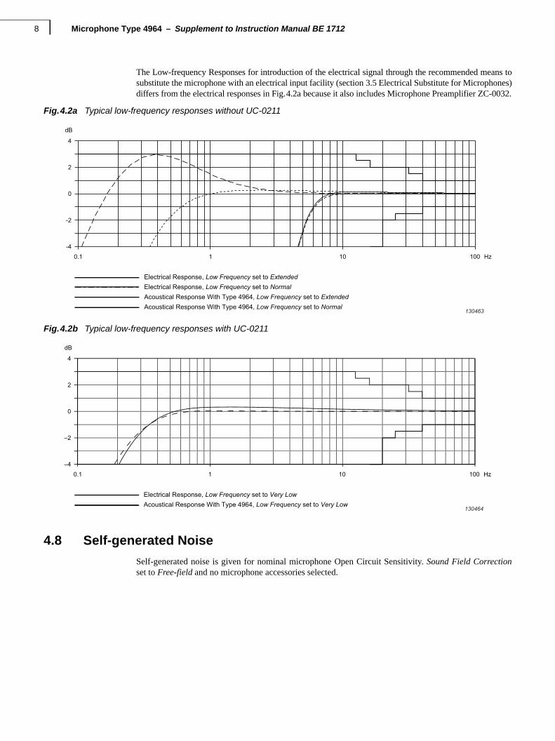
The typical Low-frequency Responses for Z frequency weighting are given in Fig.4.2a and Fig.4.2b. TheElectrical Responses are for the rear ‘Input’ socket. The Acoustical Responses include MicrophoneType 4964 and Microphone Preamplifier ZC-0032.
Low-frequency Responses depend on the state of the Low Frequency parameter on the Setup display,under Frequency Settings.
Low-frequency Responses are not influenced by the windscreen.
Low-frequency Responses are influenced by frequency response compensation.
Microphone Type 4964 – Supplement to Instruction Manual BE 17128
The Low-frequency Responses for introduction of the electrical signal through the recommended means tosubstitute the microphone with an electrical input facility (section 3.5 Electrical Substitute for Microphones)differs from the electrical responses in Fig.4.2a because it also includes Microphone Preamplifier ZC-0032.
Fig.4.2a Typical low-frequency responses without UC-0211
Fig.4.2b Typical low-frequency responses with UC-0211
4.8 Self-generated Noise
Self-generated noise is given for nominal microphone Open Circuit Sensitivity. Sound Field Correctionset to Free-field and no microphone accessories selected.
Electrical Response, Low Frequency set to ExtendedElectrical Response, Low Frequency set to NormalAcoustical Response With Type 4964, Low Frequency set to ExtendedAcoustical Response With Type 4964, Low Frequency set to Normal
130463
-4
-2
0
2
4
dB
0.1 1 10 100 Hz
Electrical Response, Low Frequency set to Very LowAcoustical Response With Type 4964, Low Frequency set to Very Low
130464
–4
–2
0
2
4
dB
0.1 1 10 100 Hz
CHAPTER 4Specifications 9
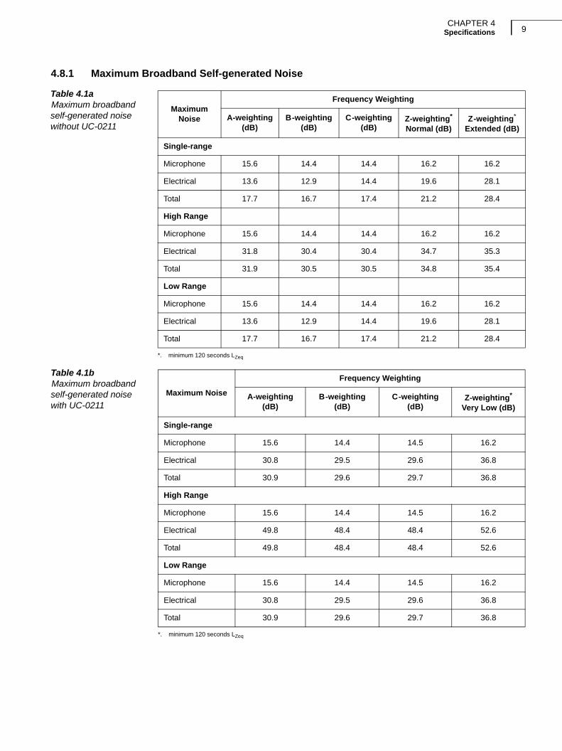
4.8.1 Maximum Broadband Self-generated Noise
Table 4.1aMaximum broadbandself-generated noise without UC-0211
Maximum Noise
Frequency Weighting
A-weighting(dB)
B-weighting(dB)
C-weighting(dB)
Z-weighting*
Normal (dB)
*. minimum 120 seconds LZeq
Z-weighting*
Extended (dB)
Single-range
Microphone 15.6 14.4 14.4 16.2 16.2
Electrical 13.6 12.9 14.4 19.6 28.1
Total 17.7 16.7 17.4 21.2 28.4
High Range
Microphone 15.6 14.4 14.4 16.2 16.2
Electrical 31.8 30.4 30.4 34.7 35.3
Total 31.9 30.5 30.5 34.8 35.4
Low Range
Microphone 15.6 14.4 14.4 16.2 16.2
Electrical 13.6 12.9 14.4 19.6 28.1
Total 17.7 16.7 17.4 21.2 28.4
Table 4.1bMaximum broadbandself-generated noise with UC-0211
Maximum Noise
Frequency Weighting
A-weighting(dB)
B-weighting(dB)
C-weighting(dB)
Z-weighting*
Very Low (dB)
*. minimum 120 seconds LZeq
Single-range
Microphone 15.6 14.4 14.5 16.2
Electrical 30.8 29.5 29.6 36.8
Total 30.9 29.6 29.7 36.8
High Range
Microphone 15.6 14.4 14.5 16.2
Electrical 49.8 48.4 48.4 52.6
Total 49.8 48.4 48.4 52.6
Low Range
Microphone 15.6 14.4 14.5 16.2
Electrical 30.8 29.5 29.6 36.8
Total 30.9 29.6 29.7 36.8
Microphone Type 4964 – Supplement to Instruction Manual BE 171210
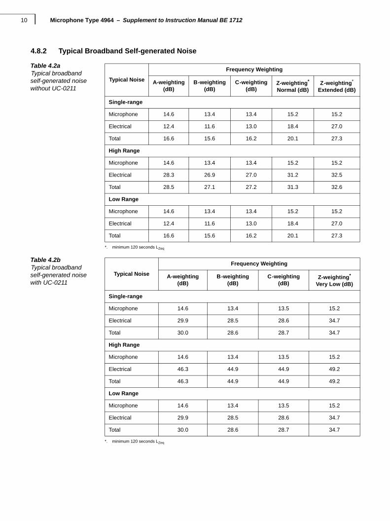
4.8.2 Typical Broadband Self-generated Noise
Table 4.2aTypical broadbandself-generated noisewithout UC-0211
Typical Noise
Frequency Weighting
A-weighting(dB)
B-weighting(dB)
C-weighting(dB)
Z-weighting*
Normal (dB)
*. minimum 120 seconds LZeq
Z-weighting*
Extended (dB)
Single-range
Microphone 14.6 13.4 13.4 15.2 15.2
Electrical 12.4 11.6 13.0 18.4 27.0
Total 16.6 15.6 16.2 20.1 27.3
High Range
Microphone 14.6 13.4 13.4 15.2 15.2
Electrical 28.3 26.9 27.0 31.2 32.5
Total 28.5 27.1 27.2 31.3 32.6
Low Range
Microphone 14.6 13.4 13.4 15.2 15.2
Electrical 12.4 11.6 13.0 18.4 27.0
Total 16.6 15.6 16.2 20.1 27.3
Table 4.2bTypical broadbandself-generated noisewith UC-0211
Typical Noise
Frequency Weighting
A-weighting(dB)
B-weighting(dB)
C-weighting(dB)
Z-weighting*
Very Low (dB)
*. minimum 120 seconds LZeq
Single-range
Microphone 14.6 13.4 13.5 15.2
Electrical 29.9 28.5 28.6 34.7
Total 30.0 28.6 28.7 34.7
High Range
Microphone 14.6 13.4 13.5 15.2
Electrical 46.3 44.9 44.9 49.2
Total 46.3 44.9 44.9 49.2
Low Range
Microphone 14.6 13.4 13.5 15.2
Electrical 29.9 28.5 28.6 34.7
Total 30.0 28.6 28.7 34.7
CHAPTER 4Specifications 11
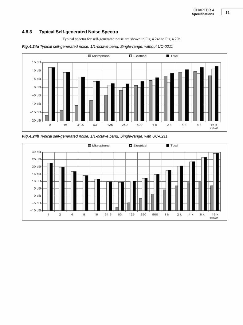
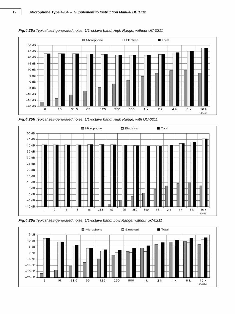
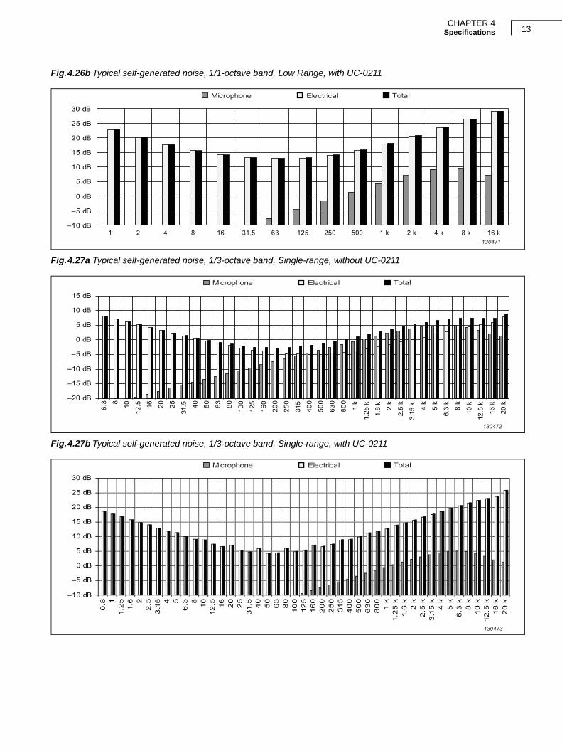
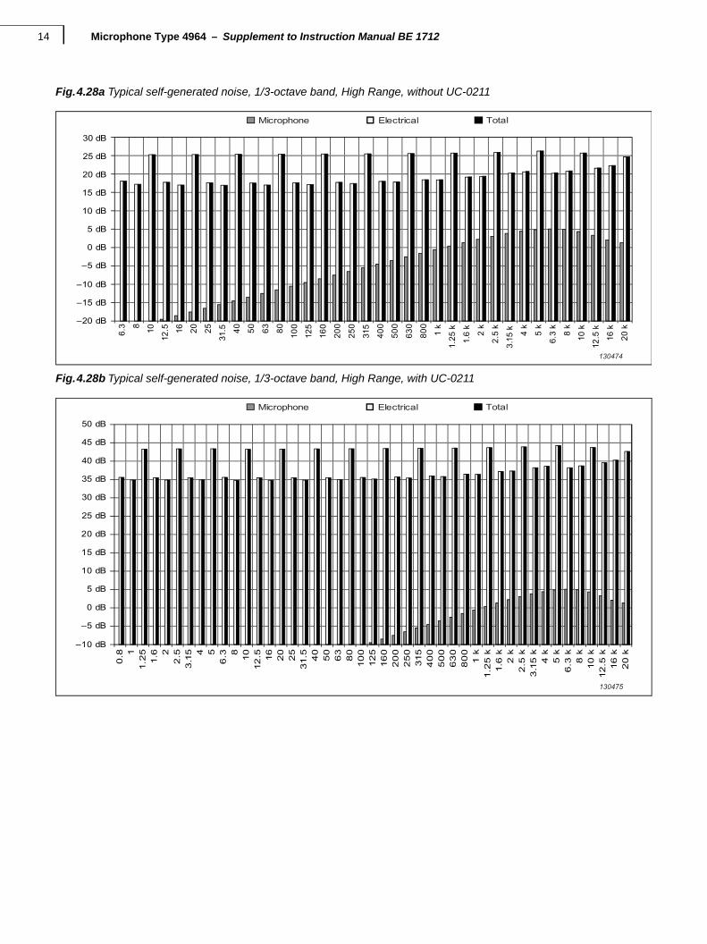
4.8.3 Typical Self-generated Noise Spectra
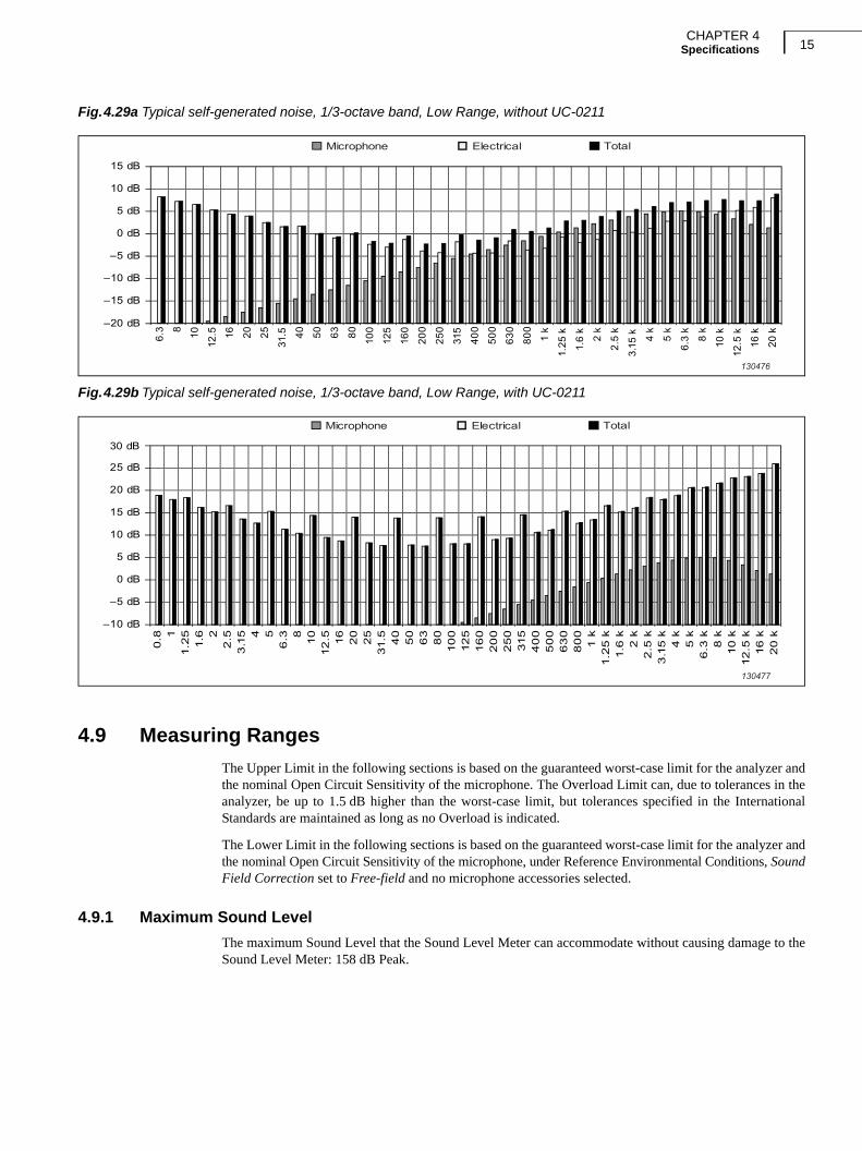
Typical spectra for self-generated noise are shown in Fig.4.24a to Fig.4.29b.
Fig.4.24a Typical self-generated noise, 1/1-octave band, Single-range, without UC-0211
Fig.4.24b Typical self-generated noise, 1/1-octave band, Single-range, with UC-0211
–20 dB
–15 dB
–10 dB
–5 dB
0 dB
5 dB
10 dB
15 dB
8 16 31.5 63 125 250 500 1 k 2 k 4 k 8 k 16 k
Microphone Electrical Total
130466
Microphone Electrical Total
841 2 16 31.5 63 125 250 500 1 k 2 k 4 k 8 k 16 k
30 dB
–10 dB
–5 dB
0 dB
5 dB
10 dB
15 dB
20 dB
25 dB
130467
Microphone Type 4964 – Supplement to Instruction Manual BE 171212
Fig.4.25a Typical self-generated noise, 1/1-octave band, High Range, without UC-0211
Fig.4.25b Typical self-generated noise, 1/1-octave band, High Range, with UC-0211
Fig.4.26a Typical self-generated noise, 1/1-octave band, Low Range, without UC-0211
Microphone Electrical Total
130468
–20 dB
–15 dB
–10 dB
–5 dB
0 dB
5 dB
10 dB
15 dB
20 dB
25 dB
30 dB
8 16 31.5 63 125 250 500 1 k 2 k 4 k 8 k 16 k
130469
–10 dB
–5 dB
0 dB
5 dB
10 dB
15 dB
20 dB
25 dB
30 dB
35 dB
40 dB
45 dB
50 dB
8 16 31.5 63 125 250 500 1 k 2 k 4 k 8 k1 2 4 16 k
Microphone Electrical Total
Microphone Electrical Total
130470
–20 dB
–15 dB
–10 dB
–5 dB
0 dB
5 dB
10 dB
15 dB
8 16 31.5 63 125 250 500 1 k 2 k 4 k 8 k 16 k
CHAPTER 4Specifications 13
Fig.4.26b Typical self-generated noise, 1/1-octave band, Low Range, with UC-0211
Fig.4.27a Typical self-generated noise, 1/3-octave band, Single-range, without UC-0211
Fig.4.27b Typical self-generated noise, 1/3-octave band, Single-range, with UC-0211
Microphone Electrical Total
130471
–10 dB
–5 dB
0 dB
5 dB
10 dB
15 dB
20 dB
25 dB
30 dB
8421 16 31.5 63 125 250 500 1 k 2 k 4 k 8 k 16 k
6.3 8 10
12.5 16 20 25
31.5 40 50 63 80 100
125
160
200
250
315
400
500
630
800
1 k
1.25
k
1.6
k
2 k
2.5
k
3.15
k 4 k
5 k
6.3
k
8 k
10 k
12.5
k
16 k
20 k
Microphone Electrical Total
130472
–20 dB
–15 dB
–10 dB
–5 dB
0 dB
5 dB
10 dB
15 dB
6.3 810
12.5 16
20
25
31.
54
05
0
0.8 1
1.2
51.
6 22
.53
.15 4 5
63
80
10
012
516
02
00
25
0315
40
05
00
63
08
00
1 k
1.2
5 k
1.6
k2
k2
.5 k
3.1
5 k
4 k
5 k
6.3
k8
k10
k12
.5 k
16
k2
0 k
Microphone Electrical Total
130473
–10 dB
–5 dB
0 dB
5 dB
10 dB
15 dB
20 dB
25 dB
30 dB
Microphone Type 4964 – Supplement to Instruction Manual BE 171214
Fig.4.28a Typical self-generated noise, 1/3-octave band, High Range, without UC-0211
Fig.4.28b Typical self-generated noise, 1/3-octave band, High Range, with UC-0211
6.3 8 10
12.5 16 20 25
31.5 40 50 63 80 100
125
160
200
250
315
400
500
630
800
1 k
1.25
k
1.6
k
2 k
2.5
k
3.15
k 4 k
5 k
6.3
k
8 k
10 k
12.5
k
16 k
20 k
Microphone Electrical Total
130474
–20 dB
–15 dB
–10 dB
–5 dB
0 dB
5 dB
10 dB
15 dB
20 dB
25 dB
30 dB
6.3 810
12.5 16
20
25
31.
54
05
0
0.8 1
1.2
51.
6 22
.53
.15 4 5
63
80
10
012
516
02
00
25
0315
40
05
00
63
08
00
1 k
1.2
5 k
1.6
k2
k2
.5 k
3.1
5 k
4 k
5 k
6.3
k8
k10
k12
.5 k
16
k2
0 k
Microphone Electrical Total
130475
–10 dB
–5 dB
0 dB
5 dB
10 dB
15 dB
20 dB
25 dB
30 dB
35 dB
40 dB
45 dB
50 dB
CHAPTER 4Specifications 15
Fig.4.29a Typical self-generated noise, 1/3-octave band, Low Range, without UC-0211
Fig.4.29b Typical self-generated noise, 1/3-octave band, Low Range, with UC-0211
4.9 Measuring Ranges
The Upper Limit in the following sections is based on the guaranteed worst-case limit for the analyzer andthe nominal Open Circuit Sensitivity of the microphone. The Overload Limit can, due to tolerances in theanalyzer, be up to 1.5 dB higher than the worst-case limit, but tolerances specified in the InternationalStandards are maintained as long as no Overload is indicated.
The Lower Limit in the following sections is based on the guaranteed worst-case limit for the analyzer andthe nominal Open Circuit Sensitivity of the microphone, under Reference Environmental Conditions, SoundField Correction set to Free-field and no microphone accessories selected.
4.9.1 Maximum Sound Level
The maximum Sound Level that the Sound Level Meter can accommodate without causing damage to theSound Level Meter: 158 dB Peak.
6.3 8 10
12.5 16 20 25
31.5 40 50 63 80 100
125
160
200
250
315
400
500
630
800
1 k
1.25
k
1.6
k
2 k
2.5
k
3.15
k 4 k
5 k
6.3
k
8 k
10 k
12.5
k
16 k
20 k
Microphone Electrical Total
130476
–20 dB
–15 dB
–10 dB
–5 dB
0 dB
5 dB
10 dB
15 dB
6.3 810
12.5 16
20
25
31.
54
05
0
0.8 1
1.2
51.
6 22
.53
.15 4 5
63
80
10
012
516
02
00
25
0315
40
05
00
63
08
00
1 k
1.2
5 k
1.6
k2
k2
.5 k
3.1
5 k
4 k
5 k
6.3
k8
k10
k12
.5 k
16
k2
0 k
Microphone Electrical Total
130477
–10 dB
–5 dB
0 dB
5 dB
10 dB
15 dB
20 dB
25 dB
30 dB
Microphone Type 4964 – Supplement to Instruction Manual BE 171216
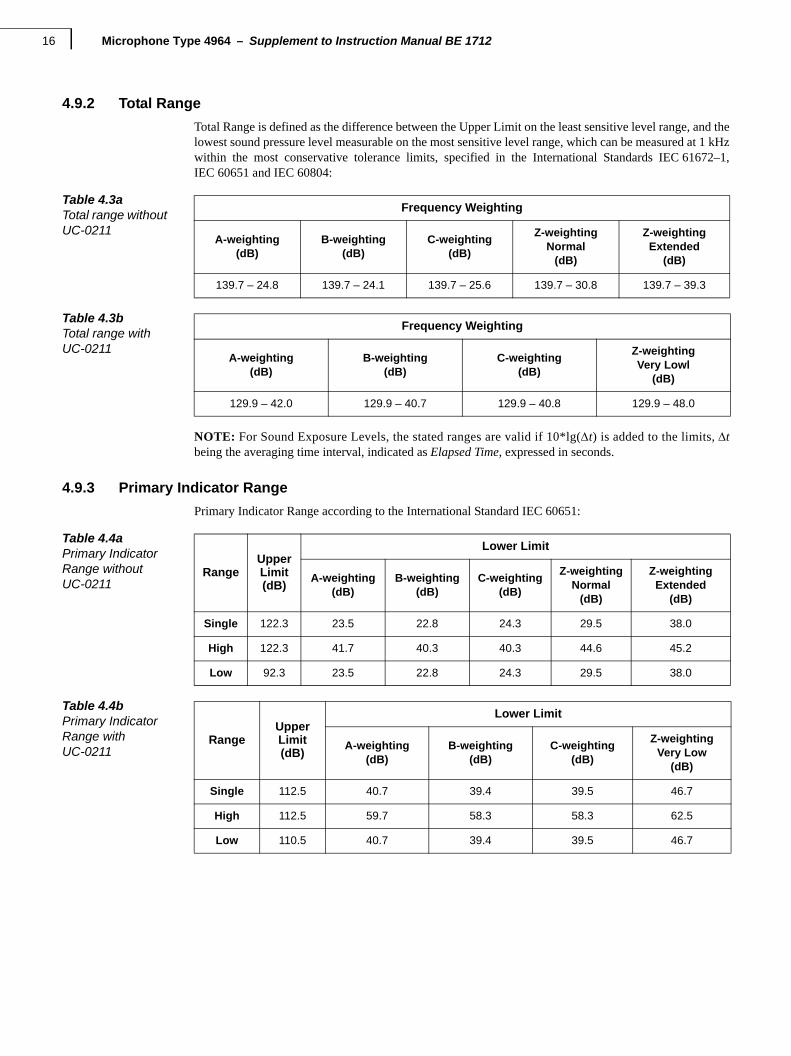
4.9.2 Total Range
Total Range is defined as the difference between the Upper Limit on the least sensitive level range, and thelowest sound pressure level measurable on the most sensitive level range, which can be measured at 1 kHzwithin the most conservative tolerance limits, specified in the International Standards IEC 61672–1,IEC 60651 and IEC 60804:
NOTE: For Sound Exposure Levels, the stated ranges are valid if 10*lg(t) is added to the limits, tbeing the averaging time interval, indicated as Elapsed Time, expressed in seconds.
4.9.3 Primary Indicator Range
Primary Indicator Range according to the International Standard IEC 60651:
Table 4.3aTotal range without UC-0211
Frequency Weighting
A-weighting(dB)
B-weighting(dB)
C-weighting(dB)
Z-weightingNormal
(dB)
Z-weightingExtended
(dB)
139.7 – 24.8 139.7 – 24.1 139.7 – 25.6 139.7 – 30.8 139.7 – 39.3
Table 4.3bTotal range with UC-0211
Frequency Weighting
A-weighting(dB)
B-weighting(dB)
C-weighting(dB)
Z-weightingVery Lowl
(dB)
129.9 – 42.0 129.9 – 40.7 129.9 – 40.8 129.9 – 48.0
Table 4.4aPrimary IndicatorRange without UC-0211
RangeUpperLimit(dB)
Lower Limit
A-weighting(dB)
B-weighting(dB)
C-weighting(dB)
Z-weightingNormal
(dB)
Z-weightingExtended
(dB)
Single 122.3 23.5 22.8 24.3 29.5 38.0
High 122.3 41.7 40.3 40.3 44.6 45.2
Low 92.3 23.5 22.8 24.3 29.5 38.0
Table 4.4bPrimary IndicatorRange with UC-0211
RangeUpperLimit(dB)
Lower Limit
A-weighting(dB)
B-weighting(dB)
C-weighting(dB)
Z-weightingVery Low
(dB)
Single 112.5 40.7 39.4 39.5 46.7
High 112.5 59.7 58.3 58.3 62.5
Low 110.5 40.7 39.4 39.5 46.7
CHAPTER 4Specifications 17
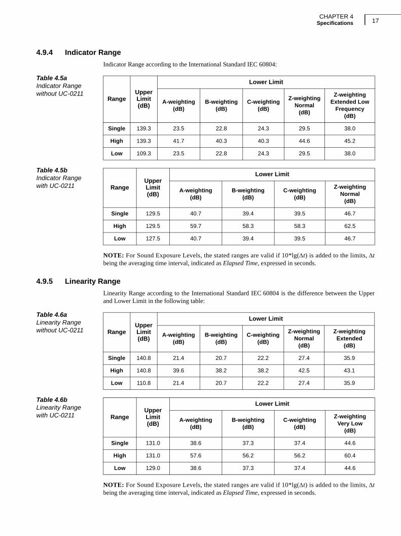
4.9.4 Indicator Range
Indicator Range according to the International Standard IEC 60804:
NOTE: For Sound Exposure Levels, the stated ranges are valid if 10*lg(t) is added to the limits, tbeing the averaging time interval, indicated as Elapsed Time, expressed in seconds.
4.9.5 Linearity Range
Linearity Range according to the International Standard IEC 60804 is the difference between the Upperand Lower Limit in the following table:
NOTE: For Sound Exposure Levels, the stated ranges are valid if 10*lg(t) is added to the limits, tbeing the averaging time interval, indicated as Elapsed Time, expressed in seconds.
Table 4.5aIndicator Range without UC-0211
RangeUpperLimit(dB)
Lower Limit
A-weighting(dB)
B-weighting(dB)
C-weighting(dB)
Z-weightingNormal
(dB)
Z-weightingExtended Low
Frequency(dB)
Single 139.3 23.5 22.8 24.3 29.5 38.0
High 139.3 41.7 40.3 40.3 44.6 45.2
Low 109.3 23.5 22.8 24.3 29.5 38.0
Table 4.5bIndicator Range with UC-0211 Range
UpperLimit(dB)
Lower Limit
A-weighting(dB)
B-weighting(dB)
C-weighting(dB)
Z-weightingNormal
(dB)
Single 129.5 40.7 39.4 39.5 46.7
High 129.5 59.7 58.3 58.3 62.5
Low 127.5 40.7 39.4 39.5 46.7
Table 4.6aLinearity Range without UC-0211 Range
UpperLimit(dB)
Lower Limit
A-weighting(dB)
B-weighting(dB)
C-weighting(dB)
Z-weightingNormal
(dB)
Z-weightingExtended
(dB)
Single 140.8 21.4 20.7 22.2 27.4 35.9
High 140.8 39.6 38.2 38.2 42.5 43.1
Low 110.8 21.4 20.7 22.2 27.4 35.9
Table 4.6bLinearity Range with UC-0211 Range
UpperLimit(dB)
Lower Limit
A-weighting(dB)
B-weighting(dB)
C-weighting(dB)
Z-weightingVery Low
(dB)
Single 131.0 38.6 37.3 37.4 44.6
High 131.0 57.6 56.2 56.2 60.4
Low 129.0 38.6 37.3 37.4 44.6
Microphone Type 4964 – Supplement to Instruction Manual BE 171218
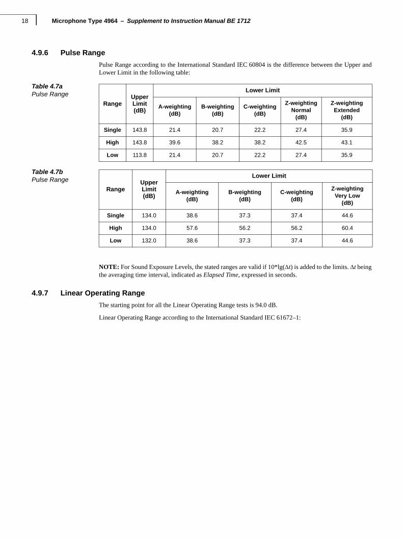
4.9.6 Pulse Range
Pulse Range according to the International Standard IEC 60804 is the difference between the Upper andLower Limit in the following table:
NOTE: For Sound Exposure Levels, the stated ranges are valid if 10*lg(t) is added to the limits. t beingthe averaging time interval, indicated as Elapsed Time, expressed in seconds.
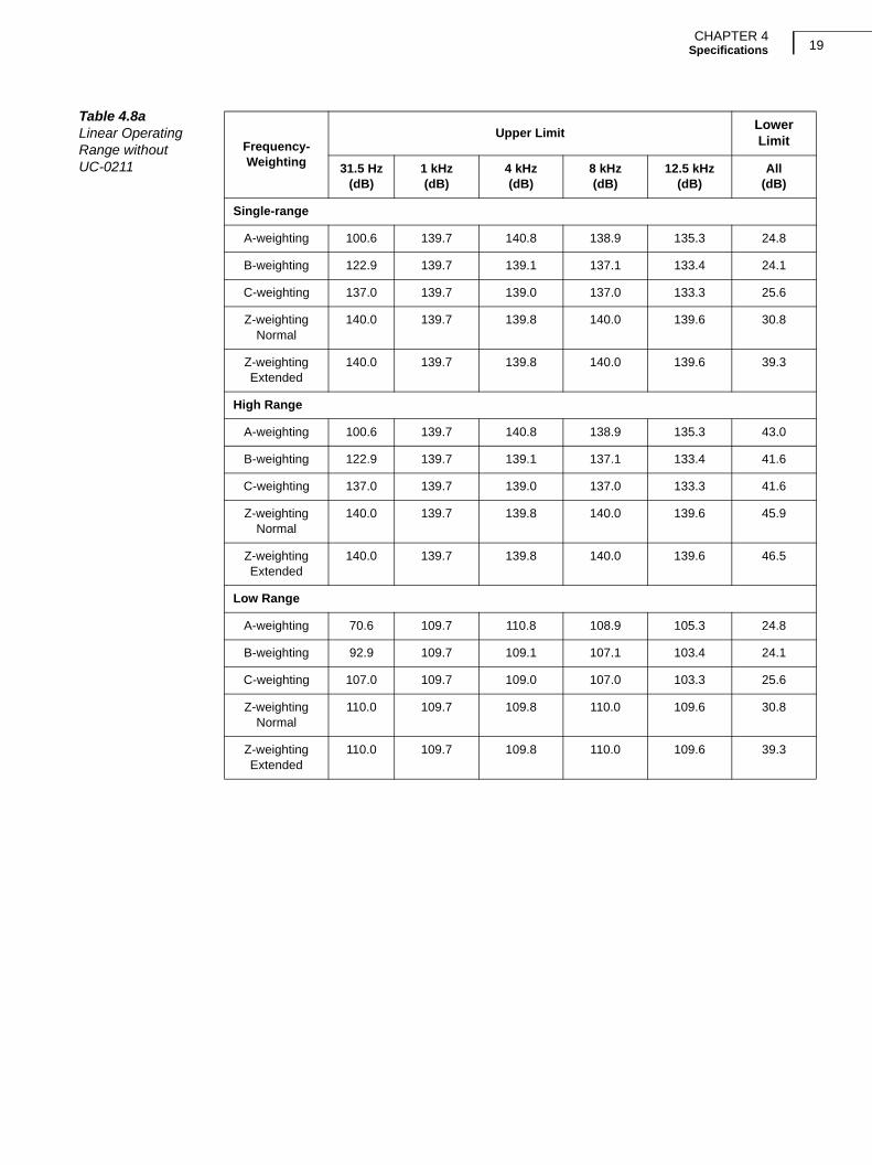
4.9.7 Linear Operating Range
The starting point for all the Linear Operating Range tests is 94.0 dB.
Linear Operating Range according to the International Standard IEC 61672–1:
Table 4.7aPulse Range
RangeUpperLimit(dB)
Lower Limit
A-weighting(dB)
B-weighting(dB)
C-weighting(dB)
Z-weightingNormal
(dB)
Z-weightingExtended
(dB)
Single 143.8 21.4 20.7 22.2 27.4 35.9
High 143.8 39.6 38.2 38.2 42.5 43.1
Low 113.8 21.4 20.7 22.2 27.4 35.9
Table 4.7bPulse Range
RangeUpperLimit(dB)
Lower Limit
A-weighting(dB)
B-weighting(dB)
C-weighting(dB)
Z-weightingVery Low
(dB)
Single 134.0 38.6 37.3 37.4 44.6
High 134.0 57.6 56.2 56.2 60.4
Low 132.0 38.6 37.3 37.4 44.6
CHAPTER 4Specifications 19
Table 4.8aLinear Operating Range without UC-0211
Frequency-Weighting
Upper LimitLowerLimit
31.5 Hz(dB)
1 kHz(dB)
4 kHz(dB)
8 kHz(dB)
12.5 kHz(dB)
All(dB)
Single-range
A-weighting 100.6 139.7 140.8 138.9 135.3 24.8
B-weighting 122.9 139.7 139.1 137.1 133.4 24.1
C-weighting 137.0 139.7 139.0 137.0 133.3 25.6
Z-weightingNormal
140.0 139.7 139.8 140.0 139.6 30.8
Z-weightingExtended
140.0 139.7 139.8 140.0 139.6 39.3
High Range
A-weighting 100.6 139.7 140.8 138.9 135.3 43.0
B-weighting 122.9 139.7 139.1 137.1 133.4 41.6
C-weighting 137.0 139.7 139.0 137.0 133.3 41.6
Z-weightingNormal
140.0 139.7 139.8 140.0 139.6 45.9
Z-weightingExtended
140.0 139.7 139.8 140.0 139.6 46.5
Low Range
A-weighting 70.6 109.7 110.8 108.9 105.3 24.8
B-weighting 92.9 109.7 109.1 107.1 103.4 24.1
C-weighting 107.0 109.7 109.0 107.0 103.3 25.6
Z-weightingNormal
110.0 109.7 109.8 110.0 109.6 30.8
Z-weightingExtended
110.0 109.7 109.8 110.0 109.6 39.3
Microphone Type 4964 – Supplement to Instruction Manual BE 171220
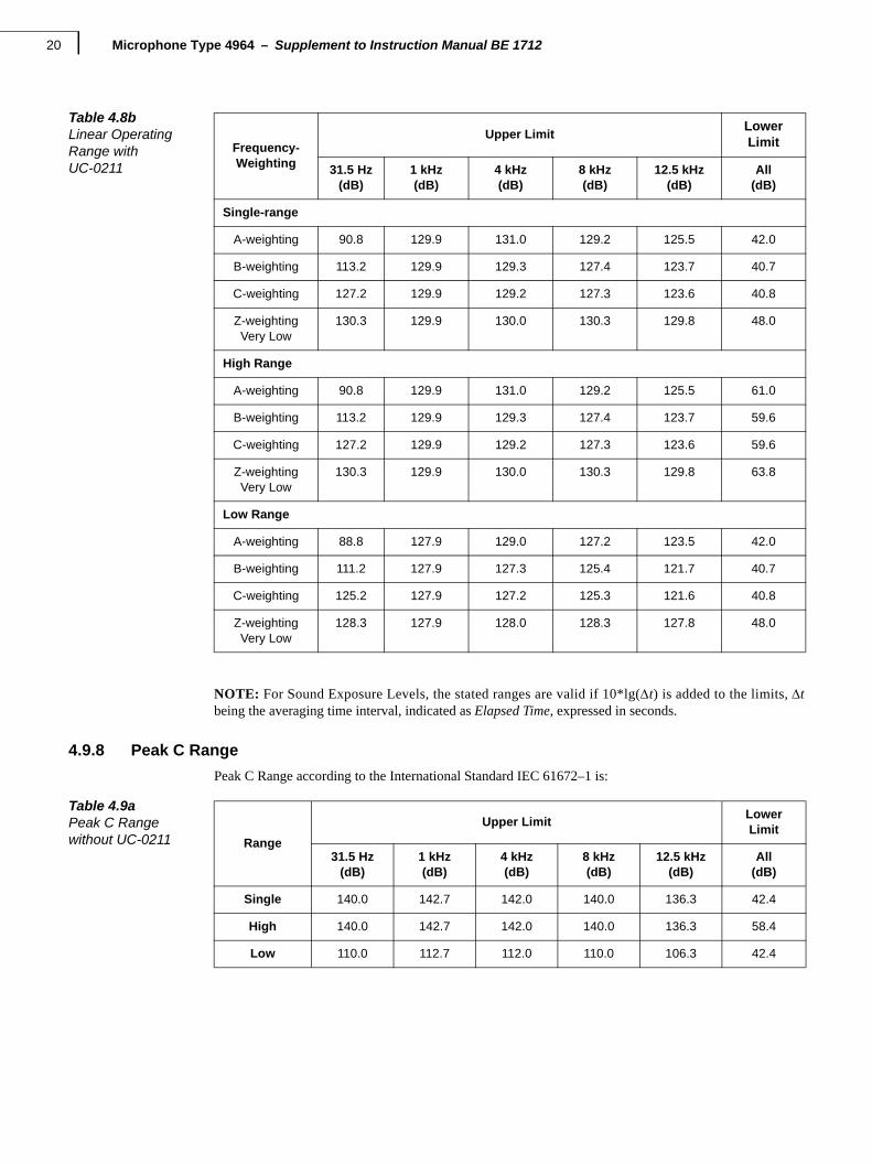
NOTE: For Sound Exposure Levels, the stated ranges are valid if 10*lg(t) is added to the limits, tbeing the averaging time interval, indicated as Elapsed Time, expressed in seconds.
4.9.8 Peak C Range
Peak C Range according to the International Standard IEC 61672–1 is:
Table 4.8bLinear Operating Range with UC-0211
Frequency-Weighting
Upper LimitLowerLimit
31.5 Hz(dB)
1 kHz(dB)
4 kHz(dB)
8 kHz(dB)
12.5 kHz(dB)
All(dB)
Single-range
A-weighting 90.8 129.9 131.0 129.2 125.5 42.0
B-weighting 113.2 129.9 129.3 127.4 123.7 40.7
C-weighting 127.2 129.9 129.2 127.3 123.6 40.8
Z-weightingVery Low
130.3 129.9 130.0 130.3 129.8 48.0
High Range
A-weighting 90.8 129.9 131.0 129.2 125.5 61.0
B-weighting 113.2 129.9 129.3 127.4 123.7 59.6
C-weighting 127.2 129.9 129.2 127.3 123.6 59.6
Z-weightingVery Low
130.3 129.9 130.0 130.3 129.8 63.8
Low Range
A-weighting 88.8 127.9 129.0 127.2 123.5 42.0
B-weighting 111.2 127.9 127.3 125.4 121.7 40.7
C-weighting 125.2 127.9 127.2 125.3 121.6 40.8
Z-weightingVery Low
128.3 127.9 128.0 128.3 127.8 48.0
Table 4.9aPeak C Range without UC-0211 Range
Upper LimitLower Limit
31.5 Hz(dB)
1 kHz(dB)
4 kHz(dB)
8 kHz(dB)
12.5 kHz(dB)
All(dB)
Single 140.0 142.7 142.0 140.0 136.3 42.4
High 140.0 142.7 142.0 140.0 136.3 58.4
Low 110.0 112.7 112.0 110.0 106.3 42.4
CHAPTER 4Specifications 21
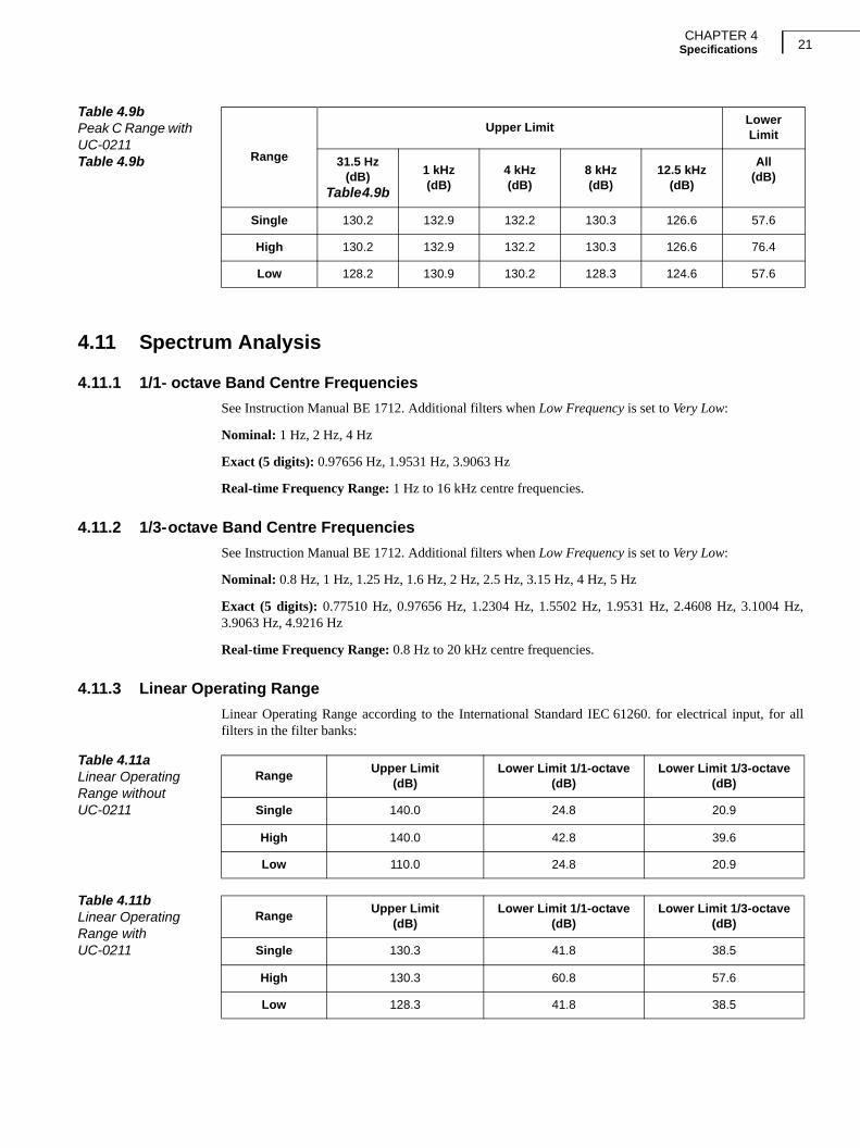
4.11 Spectrum Analysis
4.11.1 1/1- octave Band Centre Frequencies
See Instruction Manual BE 1712. Additional filters when Low Frequency is set to Very Low:
Nominal: 1 Hz, 2 Hz, 4 Hz
Exact (5 digits): 0.97656 Hz, 1.9531 Hz, 3.9063 Hz
Real-time Frequency Range: 1 Hz to 16 kHz centre frequencies.
4.11.2 1/3-octave Band Centre Frequencies
See Instruction Manual BE 1712. Additional filters when Low Frequency is set to Very Low:
Nominal: 0.8 Hz, 1 Hz, 1.25 Hz, 1.6 Hz, 2 Hz, 2.5 Hz, 3.15 Hz, 4 Hz, 5 Hz
Exact (5 digits): 0.77510 Hz, 0.97656 Hz, 1.2304 Hz, 1.5502 Hz, 1.9531 Hz, 2.4608 Hz, 3.1004 Hz,3.9063 Hz, 4.9216 Hz
Real-time Frequency Range: 0.8 Hz to 20 kHz centre frequencies.
4.11.3 Linear Operating Range
Linear Operating Range according to the International Standard IEC 61260. for electrical input, for allfilters in the filter banks:
Table 4.9bPeak C Range with UC-0211Table 4.9b Range
Upper LimitLower Limit
31.5 Hz(dB)
Table 4.9b
1 kHz(dB)
4 kHz(dB)
8 kHz(dB)
12.5 kHz(dB)
All(dB)
Single 130.2 132.9 132.2 130.3 126.6 57.6
High 130.2 132.9 132.2 130.3 126.6 76.4
Low 128.2 130.9 130.2 128.3 124.6 57.6
Table 4.11aLinear OperatingRange without UC-0211
RangeUpper Limit
(dB)Lower Limit 1/1-octave
(dB)Lower Limit 1/3-octave
(dB)
Single 140.0 24.8 20.9
High 140.0 42.8 39.6
Low 110.0 24.8 20.9
Table 4.11bLinear OperatingRange with UC-0211
RangeUpper Limit
(dB)Lower Limit 1/1-octave
(dB)Lower Limit 1/3-octave
(dB)
Single 130.3 41.8 38.5
High 130.3 60.8 57.6
Low 128.3 41.8 38.5
Microphone Type 4964 – Supplement to Instruction Manual BE 171222
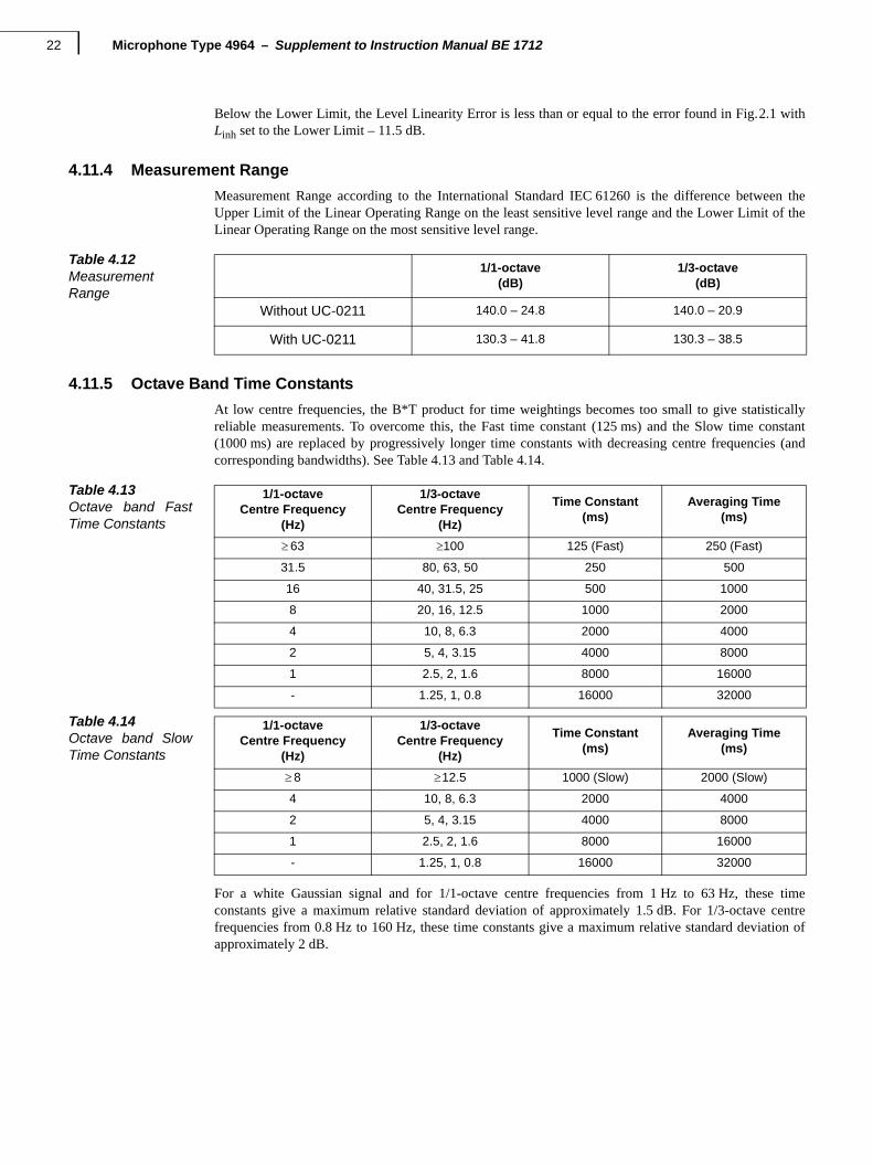
Below the Lower Limit, the Level Linearity Error is less than or equal to the error found in Fig.2.1 withLinh set to the Lower Limit – 11.5 dB.
4.11.4 Measurement Range
Measurement Range according to the International Standard IEC 61260 is the difference between theUpper Limit of the Linear Operating Range on the least sensitive level range and the Lower Limit of theLinear Operating Range on the most sensitive level range.
4.11.5 Octave Band Time Constants
At low centre frequencies, the B*T product for time weightings becomes too small to give statisticallyreliable measurements. To overcome this, the Fast time constant (125 ms) and the Slow time constant(1000 ms) are replaced by progressively longer time constants with decreasing centre frequencies (andcorresponding bandwidths). See Table 4.13 and Table 4.14.
For a white Gaussian signal and for 1/1-octave centre frequencies from 1 Hz to 63 Hz, these timeconstants give a maximum relative standard deviation of approximately 1.5 dB. For 1/3-octave centrefrequencies from 0.8 Hz to 160 Hz, these time constants give a maximum relative standard deviation ofapproximately 2 dB.
Table 4.12MeasurementRange
1/1-octave(dB)
1/3-octave(dB)
Without UC-0211 140.0 – 24.8 140.0 – 20.9
With UC-0211 130.3 – 41.8 130.3 – 38.5
Table 4.13Octave band FastTime Constants
1/1-octaveCentre Frequency
(Hz)
1/3-octaveCentre Frequency
(Hz)
Time Constant(ms)
Averaging Time(ms)
63 100 125 (Fast) 250 (Fast)
31.5 80, 63, 50 250 500
16 40, 31.5, 25 500 1000
8 20, 16, 12.5 1000 2000
4 10, 8, 6.3 2000 4000
2 5, 4, 3.15 4000 8000
1 2.5, 2, 1.6 8000 16000
- 1.25, 1, 0.8 16000 32000
Table 4.14Octave band SlowTime Constants
1/1-octaveCentre Frequency
(Hz)
1/3-octaveCentre Frequency
(Hz)
Time Constant(ms)
Averaging Time(ms)
8 12.5 1000 (Slow) 2000 (Slow)
4 10, 8, 6.3 2000 4000
2 5, 4, 3.15 4000 8000
1 2.5, 2, 1.6 8000 16000
- 1.25, 1, 0.8 16000 32000

CHAPTER 4Specifications 23
4.12 Influence from the Operating Environment
4.12.4 Vibration
Vibration Sensitivity (20 – 1000 Hz) for 1 ms–2: A-weighted max. 76 dB, Z-weighted max. 86 dBwithout UC-0211, A-weighted max 93 dB, Z-weighted max 103 dB with UC-0211.

Microphone Type 4964 – Supplement to Instruction Manual BE 171224
25
Appendix EG-weighting
E.1 Introduction
G-weighting is not specified in the Sound Level Meter standard IEC 61672–1 (2002–05), but it states inparagraph 5.4.12:
“If a sound level meter provides one or more optional frequency responses, the instruction manual shallstate the design-goal frequency response and the tolerance limits that are maintained around the designgoal(s). If an optional frequency response is specified in an International Standard, the design-goalfrequency response shall be as specified in that International Standard....”
Concerning Level Linearity, the standard states in paragraph 5.5.7:
“The specifications in 5.5.5 and 5.5.6 apply over the total range for any frequency within the frequencyrange of the sound level meter and for any frequency weighting or frequency response provided.”
G-weighting covers a substantially different frequency range from that of the Sound Level Meter standardIEC 61672–1; therefore, it is neither possible nor relevant to fulfil the above completely, but in the specifi-cation below we have tried to be as loyal to it as possible.
E.2 Frequency Weighting
Both broadband and spectrum measurements can be frequency weighted with G-weighting.
The G-weightings conform to the requirements in ISO 7196:1995 and ANSI S1.42–2001 (R2011).
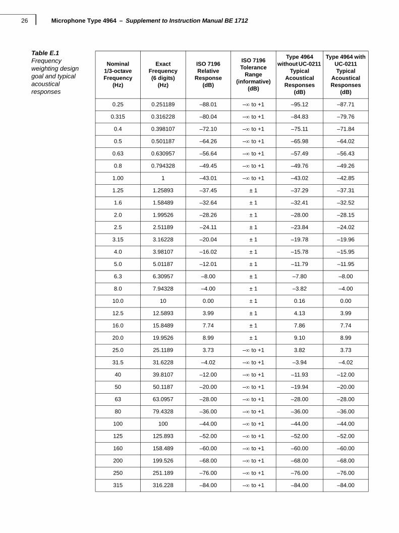
Table 2.1 states the design goal frequency responses for the frequency weighting and the typical acousticalresponses for the two microphone configurations:
• Type 4964 without UC-0211 and Low Frequency is set to Extended
• Type 4964 with UC-0211 and Low Frequency is set to Very Low
At these low frequencies there are no significant influences from windscreens and sound fields.
Microphone Type 4964 – Supplement to Instruction Manual BE 171226
.
Table E.1Frequency weighting design goal and typical acoustical responses
Nominal1/3-octaveFrequency
(Hz)
Exact Frequency(6 digits)
(Hz)
ISO 7196Relative
Response(dB)
ISO 7196Tolerance
Range(informative)
(dB)
Type 4964without UC-0211
TypicalAcousticalResponses
(dB)
Type 4964 with UC-0211Typical
AcousticalResponses
(dB)
0.25 0.251189 –88.01 – to +1 –95.12 –87.71
0.315 0.316228 –80.04 – to +1 –84.83 –79.76
0.4 0.398107 –72.10 – to +1 –75.11 –71.84
0.5 0.501187 –64.26 – to +1 –65.98 –64.02
0.63 0.630957 –56.64 – to +1 –57.49 –56.43
0.8 0.794328 –49.45 – to +1 –49.76 –49.26
1.00 1 –43.01 – to +1 –43.02 –42.85
1.25 1.25893 –37.45 ± 1 –37.29 –37.31
1.6 1.58489 –32.64 ± 1 –32.41 –32.52
2.0 1.99526 –28.26 ± 1 –28.00 –28.15
2.5 2.51189 –24.11 ± 1 –23.84 –24.02
3.15 3.16228 –20.04 ± 1 –19.78 –19.96
4.0 3.98107 –16.02 ± 1 –15.78 –15.95
5.0 5.01187 –12.01 ± 1 –11.79 –11.95
6.3 6.30957 –8.00 ± 1 –7.80 –8.00
8.0 7.94328 –4.00 ± 1 –3.82 –4.00
10.0 10 0.00 ± 1 0.16 0.00
12.5 12.5893 3.99 ± 1 4.13 3.99
16.0 15.8489 7.74 ± 1 7.86 7.74
20.0 19.9526 8.99 ± 1 9.10 8.99
25.0 25.1189 3.73 – to +1 3.82 3.73
31.5 31.6228 –4.02 – to +1 –3.94 –4.02
40 39.8107 –12.00 – to +1 –11.93 –12.00
50 50.1187 –20.00 – to +1 –19.94 –20.00
63 63.0957 –28.00 – to +1 –28.00 –28.00
80 79.4328 –36.00 – to +1 –36.00 –36.00
100 100 –44.00 – to +1 –44.00 –44.00
125 125.893 –52.00 – to +1 –52.00 –52.00
160 158.489 –60.00 – to +1 –60.00 –60.00
200 199.526 –68.00 – to +1 –68.00 –68.00
250 251.189 –76.00 – to +1 –76.00 –76.00
315 316.228 –84.00 – to +1 –84.00 –84.00
APPENDIX EG-weighting 27
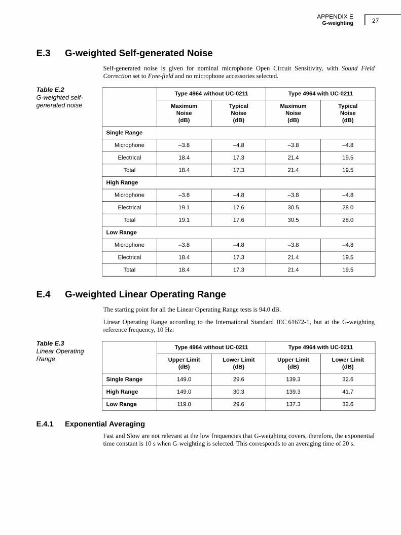
E.3 G-weighted Self-generated Noise
Self-generated noise is given for nominal microphone Open Circuit Sensitivity, with Sound FieldCorrection set to Free-field and no microphone accessories selected.
E.4 G-weighted Linear Operating Range
The starting point for all the Linear Operating Range tests is 94.0 dB.
Linear Operating Range according to the International Standard IEC 61672-1, but at the G-weightingreference frequency, 10 Hz:
E.4.1 Exponential Averaging
Fast and Slow are not relevant at the low frequencies that G-weighting covers, therefore, the exponentialtime constant is 10 s when G-weighting is selected. This corresponds to an averaging time of 20 s.
Table E.2G-weighted self-generated noise
Type 4964 without UC-0211 Type 4964 with UC-0211
MaximumNoise(dB)
Typical Noise(dB)
MaximumNoise(dB)
Typical Noise(dB)
Single Range
Microphone –3.8 –4.8 –3.8 –4.8
Electrical 18.4 17.3 21.4 19.5
Total 18.4 17.3 21.4 19.5
High Range
Microphone –3.8 –4.8 –3.8 –4.8
Electrical 19.1 17.6 30.5 28.0
Total 19.1 17.6 30.5 28.0
Low Range
Microphone –3.8 –4.8 –3.8 –4.8
Electrical 18.4 17.3 21.4 19.5
Total 18.4 17.3 21.4 19.5
Table E.3Linear Operating Range
Type 4964 without UC-0211 Type 4964 with UC-0211
Upper Limit(dB)
Lower Limit(dB)
Upper Limit(dB)
Lower Limit(dB)
Single Range 149.0 29.6 139.3 32.6
High Range 149.0 30.3 139.3 41.7
Low Range 119.0 29.6 137.3 32.6

Microphone Type 4964 – Supplement to Instruction Manual BE 171228
29
Index
AAbout This Manual ........................................................................... 1ANSI S1.42–2001 .......................................................................... 25
BB*T Product .................................................................................... 22
CCapacitance ..................................................................................... 7Components Included with Type 2250/2270.................................... 1Conformance Testing....................................................................... 5
DDescriptions ..................................................................................... 3
EExponential Averaging ................................................................... 27Extended Dynamic Range Mode ..................................................... 3Extension Cables ............................................................................. 7
FFast Time Constant ........................................................................ 22Free-field ........................................................................................ 27Frequency Responses ..................................................................... 7Frequency weighting design goal................................................... 26
GG-weighting ............................................................................. 25, 27
IIEC 61672-1 ................................................................................... 27IEC 61672–1 .................................................................................. 25Indicator Range.............................................................................. 17Instruction Manual ............................................................................ 1Introduction ...................................................................................... 1ISO 7196
1995 .......................................................................................... 25
LLinear Operating Range....................................................18, 21, 27Linearity Range .............................................................................. 17Lower Limit ..................................................................................... 15
MMaximum Broadband Self-generated Noise.....................................9Maximum Sound Level ...................................................................15Measurement Range ......................................................................22Measuring Ranges .........................................................................15Microphone.......................................................................................7Microphone Reference Point ............................................................7
NNominal Open Circuit Sensitivity ......................................................7Nominal Preamplifier Attenuation .....................................................7
OOpen Circuit Sensitivity ........................................................... 15, 27Overload Limit ................................................................................15
PPeak C Range ................................................................................20Primary Indicator Range.................................................................16Pulse Range ...................................................................................18
RReal-time frequency range .............................................................21Reference Direction of Sound Incidence ..........................................7Reference Environmental Conditions ...............................................7
SSelf-generated Noise................................................................. 8, 27Slow Time Constant .......................................................................22Sound Field Correction...................................................................27
TTotal Range ....................................................................................16Typical Broadband Self-generated Noise.......................................10Typical Self-generated Noise Spectrums .......................................11
UUC-0211 .........................................................................................25Upper Limit .....................................................................................15User Manual BE 1713.......................................................................1
VVibration .........................................................................................23Vibration Sensitivity ........................................................................23

Microphone Type 4964 – Supplement to Instruction Manual BE 171230


TechnicalDocumentation
Microphone Type 4964for Hand-held Analyzer Types 2250, 2250-L and 2270
Supplement to Instruction Manual BE 1712
HEADQUARTERS: Brüel & Kjær Sound & Vibration Measurement A/S · DK-2850 Nærum · DenmarkTelephone: +45 7741 2000 · Fax: +45 4580 1405 · www.bksv.com · [email protected]
Local representatives and service organisations worldwide
ËBE-1748---JÎ
English BE 1864 – 11