Embed Size (px)
Citation preview
CXC 13/O /SYLL 00A1
CARIBBEAN EXAMINATIONS COUNCIL
Caribbean Secondary Education Certificate
CSEC®
TECHNICAL DRAWING SYLLABUS
Effective for examinations from May/June 2002
Including 2006 amendments

CXC 13/O /SYLL 00/A1 ii
Published by the Caribbean Examinations Council
All rights reserved. No part of this publication may be reproduced, stored in a retrieval system, or transmitted in any form, or by any means electronic, photocopying, recording or otherwise without prior permission of the author or publisher.
Correspondence related to the syllabus should be addressed to:
The Pro-Registrar Caribbean Examinations Council Caenwood Centre 37 Arnold Road, Kingston 5, Jamaica, W.I.
Telephone: (876) 630-5200 Facsimile Number: (876) 967-4972 E-mail address: [email protected] Website: www.cxc.org
Copyright © 2000, by Caribbean Examinations Council The Garrison, St Michael BB14038, Barbados

CXC 13/O /SYLL 00/A1 iii
Content
Rationale for Teaching Technical Drawing ...................................................................................... 1
General Objectives ..............................................................................................................................1
Organization of the Syllabus ............................................................................................................... 3-5
Format of the Examination................................................................................................................. 5-8
Unit 1 – Plane and Solid Geometry ................................................................................................... 9-16
Unit 2 – Building Drawing ............................................................................................................... 17-20
Unit 3 – Mechanical Engineering Drawing .................................................................................... 21-24
Recommended Minimum Equipment /Material for Technical Drawing Syllabus ..................... 25-27
Recommended Texts ........................................................................................................................... 28

CXC 13/O /SYLL 00/A1 iv
AMENDMENTS The Technical Drawing Syllabus, previously included in the Industrial Arts Syllabus, is now published under its own cover. The syllabus was revised in 2000 for first examination in 2002. The major amendments are indicated by vertical lines.
Attention is drawn to the following:
i) the organisation of the syllabus into Units and Modules;
ii) the merging of the Plane and the Solid Geometry sections into Unit1:
Plane and Solid Geometry;
iii) the revision of the percentage weighting of papers and profile dimensions;
iv) the rewriting of Unit 3: Mechanical Engineering Drawing;
v) the restructuring of the School-Based Assessment component;
vi) the addition of Computer Aided Drafting as an option.
Technical Drawing Syllabus
◆ RATIONALE FOR TEACHING TECHNICAL DRAWING
It is generally recognised that Technical Drawing is the language of communication of technical/vocational occupations and as such, has widespread applications in the life of consumers. It is, therefore, being recommended that every secondary school student should have, at the minimum, a basic knowledge of Technical Drawing.
To this end, the Caribbean Examinations Council recognises the need to provide a programme of studies in Technical Drawing which will cater not only to the above stated interest, but also to those students who will proceed to studies at tertiary levels and/or seek entry level employment in related fields.
The Technical Drawing course as conceived, therefore, will be an essential companion to the cognate CSEC Industrial Technology programme as well as an integral component of the General Education curriculum.
The syllabus also contributes to the development of selected attributes from the CARICOM Ideal Person document as articulated by the CARICOM Heads of Government. This person is one who demonstrates emotional security with a high level of self-confidence and self-esteem, is aware of the importance of living in harmony with the environment and nurtures its development in the economic and entrepreneurial spheres in all other areas of life (CARICOM Education Strategy, 2000). This holistic development of students aligns with selected competencies advocated in the UNESCO Pillars of learning. These are learning to be, learning to do, and learning to transform one’s self and society.
◆ GENERAL OBJECTIVES
This syllabus is designed for candidates to:
(i) develop an understanding of and appreciation of Technical Drawing in the Caribbean Industrial Society;
(ii) discover and develop their talents in the fields of Technical Drawing and related
technologies;
(iii) develop technical problem-solving skills in Technical Drawing as related to materials and
CXC 13/O /SYLL 00/A1 1

processes;
(iv) develop the correct and accepted Technical Drawing skills as demanded by Industry;
(v) be aware of the career opportunities available in Technical Drawing and its related fields;
(vi) have a working knowledge and understanding of Computer Aided Drafting applications;
(vii) develop skills to use drawing in the process of design.
◆ CERTIFICATION AND DEFINITION OF PROFILES
The Technical Drawing course is an integral component of the Technical/Vocational Education programme offered by the Council. Commencing May/June 2005, Technical Drawing will be examined for certification at the General Proficiency only1. Ca n d i d a t e s h a v e t h e o p t i o n o f us i n g t he C o m put e r - Ai d e d D r a f t i n g ( CAD ) m e t h o d / a p p l i c a t i o n t o c o m p l e t e P a p e r 0 2 , Pa p e r 0 3 a n d t h e S B A c o m p o n e n t o f t h e s y l l a b u s .
Candidates will be awarded an overall grade reported on a 6-point scale, that is, Grades 1-6. In addition to the overall grade, candidate’s performance will also be reported under the profile dimensions, Knowledge, Application and Practical Ability.
Definitions
Knowledge Recall and comprehension of terms, principles, methods, theories and structures; interpretation and extrapolation;
Application Use of concepts, principles, methods and theories to solve
problems in a given situation; analysis, synthesis and evaluation;
Practical Ability Demonstration of manipulative skills involving the use of drawing instruments, equipment and materials in problem solving situations.
CANDIDATE POPULATION
The syllabus is designed to be covered in the final two years of the five-year secondary school programme and is intended for students enrolled in a full-time programme. However, candidates who do not attend school full-time may undertake the course by observing the following guidelines:
A. Regulations for Private Institutions
(i) Candidates entering for the examination through private institutions recognized
1Please refer to letter dated November 4, 2002 to Ministries of Education, Schools and Local Registrars.
CXC 13/O /SYLL 00/A1 2

by the Council will be required to complete all the components of the respective proficiencies.
(i) The School-Based Assessment of such candidates must be monitored by the tutors in the institution through which they register.
B. Regulations for Private Candidates
(i) “A private candidate is one not entered through a school or other approved educational institution”.
(ii) A private candidate will be required to complete all the components of the
respective proficiencies.
(iii) A private candidate must identify a teacher/tutor from a registered institution (school/technical institute/community college) who will assess and approve the candidate’s submission for the School-Based Assessment component of the syllabus. The name, school, and territory of the identified teacher/tutor should be submitted to the Council on registration for the subject.
ALLIED SUBJECTS
School candidates should be encouraged to include the following subjects in their programme of study: one of the Industrial Technology subjects (Building Technology; Mechanical Engineering Technology; Electrical and Electronic Technology), English A, Mathematics, Physics.
SUGGESTED TIME ALLOCATION
It is recommended that a minimum of five 40-minute periods per week with no single period be allocated to the subject over a two-year period.
◆ ORGANIZATION OF THE SYLLABUS
The syllabus is divided into three Units:
UNIT 1 - Plane and Solid Geometry UNIT 2 - Building Drawing UNIT 3 - Mechanical Engineering Drawing
Candidates are expected to undertake UNIT 1: Plane and Solid Geometry and EITHER UNIT 2: Building Drawing OR UNIT 3: Mechanical Engineering Drawing.
CERTIFICATION AND DEFINITION OF PROFILES
The Technical Drawing course is an integral component of the Technical/Vocational Education programme offered by the Council. It will, therefore, be examined for certification at both Basic and General Proficiencies. Candidates have the option of using either the Traditional Drawing Method (drawing board and tee square) or Computer Aided Drafting method/applications to
CXC 13/O /SYLL 00/A1 3
complete the objectives of the syllabus.
Candidates will be awarded an overall grade reported on a 6-point scale, that is, Grades 1-6. In addition to the overall grade, candidate’s performance will also be reported under the profile dimensions, Knowledge, Application and Practical Ability.
DEFINITIONS
Knowledge Recall and comprehension of terms, principles, methods, theories and
structures; interpretation and extrapolation;
Application Use of concepts, principles, methods and theories to solve problems in a given situation; analysis, synthesis and evaluation;
Practical Ability Demonstration of manipulative skills involving the use of drawing
instruments, equipment and materials in problem solving situations.
(Distinction between Basic and General Proficiency)
The Basic Proficiency or “Core” syllabus provides the minimum Technical Drawing skills and competencies.
For the General Proficiency, the syllabus is augmented by additional modules to ensure a more extensive knowledge and understanding of the subject. General Proficiency candidates will normally be expected to proceed to further studies in their chosen subject areas and should be able to respond at a higher level to any of the modules listed in the syllabus, so as to demonstrate their ability to recall and apply the knowledge gained in the solution of problems of a practical nature.
Accordingly, the examinations for Basic Proficiency and General Proficiency differ in:
(i) the extent of the syllabus content to be covered;
(ii) the degree of difficulty of questions in papers other than Paper 1;
(iii) the relative importance of the three profile dimensions - Knowledge, Application,
Practical Ability; The syllabus coverage required is as follows:
BASIC PROFICIENCY
UNIT 1: All areas except Module IX, Auxiliary Projections and Module (Plane and Solid Geometry) XI, Helical Curves.
CXC 13/O /SYLL 00/A1 4

EITHER UNIT 2: (Building Drawing) All areas except detailed section of staircases, walls and floors.
UNIT 3: (Mechanical Engineering Drawing) All areas except Sectional Assembly Drawings.
GENERAL PROFICIENCY UNIT 1: (Plane and Solid Geometry) All areas
EITHER UNIT 2: (Building
Drawing) All areas
OR UNIT 3: (Mechanical Engineering Drawing) All areas
◆ FORMAT OF THE EXAMINATION
BASIC PROFICIENCY
Paper 01 A paper common to Basic and General Proficiencies. Sixty (60) multiple (¼ hours) choice items on Unit 1 (except Auxiliary Projection, Module IX
and Helical Curves, Module XI) - Knowledge, Application and Practical Ability will be tested in the approximate ratio 5:4:1. Each item will be worth one mark.
Paper 02 Plane and Solid Geometry (1½ hours) Six structured questions on the same Unit as Paper 1 – three
questions will be set on Modules I-VI and three on Modules VII, VIII and X. Candidates must attempt three questions but not more than two from any part. Each question will be worth 20 marks distributed in the approximate ratio: Knowledge 3: Application 7: Practical Ability 10.
Paper 03 Building or Mechanical Engineering Drawing (Traditional) (2½ hours) Six structured questions testing the objectives of Modules in Unit
2: Building Drawing and Unit 3: Mechanical Engineering Drawing. Three questions will be set on Building Drawing and three on Mechanical Engineering Drawing. Candidates must attempt two questions: one working/assembly drawing and one sketch and design (from area of choice). The working/assembly drawing will be worth 60 marks of which 10 marks will be for (Knowledge), 20 for (Application) and 30 for (Practical Ability). The sketch and design question will be worth 20 marks of which 5 will be for (Knowledge), 7 for (Application) and 8 for (Practical Ability).
CXC 13/O /SYLL 00/A1 5

OR
Paper 03 Building or Mechanical Engineering Drawing (Computer) (2½ hours) Six structured questions testing the objectives of Modules in Unit
2: Building Drawing and Unit 3: Mechanical Engineering Drawing. Three questions will be set on Building Drawing and three on Mechanical Engineering Drawing. Candidates must attempt two questions: one 2D working/assembly drawing and one 3D solid model design drawing (from area of choice). The working/assembly drawing will be worth 60 marks of which 10 marks will be for (Knowledge), 20 for (Application) and 30 for (Practical Ability). The solid model design drawing question will be worth 20 marks of which 5 will be for (Knowledge), 7 for (Application) and 8 for (Practical Ability).
BASIC PROFICIENCY
School-Based Assessment
During the fourth and fifth terms of the course, candidates will be required to complete a project testing the candidates’ ability to design/redesign a Building component or Mechanical Engineering device/gadget to solve a simple functional problem in one of the ten categories, viz:
Categories
I) Household vi) Business/Office ii) Education facilities vii) Power iii) Agriculture/Fishing viii) Recreation iv) Health facilities ix) Construction v) Transportation x) Manufacturing
The drawing project will carry 50 marks – 5 for Knowledge, 20 for Application and 25 for Practical Ability and will account for 20% of the composite score.
Candidates will be required to prepare a complete set of working drawings of the Building component or Mechanical Engineering device/gadget. Sketches, working/assembly drawings should be kept in a portfolio (laboratory book) which will be assessed by the teacher.
NB: The drawing project must be done in its entirety in the classroom/laboratory under the
supervision of a teacher. It is anticipated that the project will not be done under examination conditions. However, the teacher is expected to ensure that the project is developed under his/her supervision and reflects solely the candidate’s efforts. Candidates selecting the Traditional Drawing Method may complete the SBA drawing project using the Computer Aided Drafting Method/applications.
CXC 13/O /SYLL 00/A1 6

GENERAL PROFICIENCY
Paper 01 A paper common to Basic and General Proficiencies. Sixty (60) multiple (1¼ hours) choice items on Unit 1 (except Auxiliary Projection Module IX and
Helical Curves Module XI) – Knowledge, Application and Practical Ability will be tested in the approximate ratio 5:4:1. Each item will be worth one mark.
Paper 02 Plane and Solid Geometry (1½ hours) Eight questions on Modules of Unit 1– four questions will be set on
Modules I – VI and four on Modules VII - XI. Candidates must attempt four questions, two from each part. Each question will be worth 20 marks distributed in the ratio 4:7:9 for (Knowledge), (Application), and (Practical Ability).
Paper 03 Building and Mechanical Engineering Drawing (By Traditional Method) (3 hours) Eight questions testing the objectives of Modules in Unit 2: Building
Drawing and Unit 3: Mechanical Engineering Drawing of the syllabus. Four questions on Building Drawing and four questions on Mechanical Engineering Drawing. Candidates must attempt two questions: one sectional working/assembly drawing and one sketch and design from area of choice. The sectional working/assembly drawing question will be worth 80 marks of which 16 will be for (Knowledge), 32 for (Application) and 32 for (Practical Ability). The sketch and design question will be worth 20 marks of which 3 will be for (Knowledge), 7 for (Application) and 10 for (Practical Ability).
OR
Paper 03 Building and Mechanical Engineering Drawing (By Computer) (3 hours) Eight questions testing the objectives of Modules in Unit 2: Building
Drawing and Unit 3: Mechanical Engineering Drawing of the syllabus. Four questions on Building Drawing and four questions on Mechanical Engineering Drawing. Candidates must attempt two questions: one sectional 2D working/assembly drawing and one 3D solid model design drawing from area of choice. The sectional working/assembly drawing question will be worth 80 marks of which 16 will be for (Knowledge), 32 for (Application) and 32 for (Practical Ability). The 3D solid model and design drawing question will be worth 20 marks of which 3 will be for (Knowledge), 7 for (Application) and 10 for (Practical Ability).
SCHOOL-BASED ASSESSMENT
Apart from the allocation of marks, the project is the same as for the Basic Proficiency. However, candidates must include a full or part sectional view of the fully assembled component or device/gadget for the Building or Mechanical Engineering Unit. The project will carry 60 marks – 6 for Knowledge, 24 for Application and 30 for Practical Ability and will account for 20% of the composite score.
CXC 13/O /SYLL 00/A1 7

REGULATIONS FOR RESIT CANDIDATES
Resit candidates who obtained 50% or more of the SBA total may choose not to repeat their SBA provided that they rewrite the examination not later than the subsequent year.
Candidates who obtained less than 50% of the total SBA marks must be re-assessed during Terms 1 and 2 of the year of the examination.
WEIGHTING
The percentage weighting of the examination components is as follows:
Paper 1
Basic
24
General
20 Paper 2 24 27 Paper 3 32 33
School-Based Assessment
20 20
DISTRIBUTION OF MARKS BY PAPER AND PROFILE
Profiles
Basic Proficiency General Proficiency
Paper 1 Paper 2 Paper 3 SBA Total Paper 1 Paper 2 Paper 3 SBA Total
Knowledge 30 9 15 5 59 30 16 19 6 71
Application 24 21 27 20 92 24 28 39 24 115
Practical Ability
6 30 38 25 99 6 36 42 30 114
60 60 80 50 250 60 80 100 60 300
The percentage weighting of the Profile dimensions is as follows:
Profile Basic General
Knowledge 24 24 Application 37 38 Practical Ability 39 38
CXC 13/O /SYLL 00/A1 8
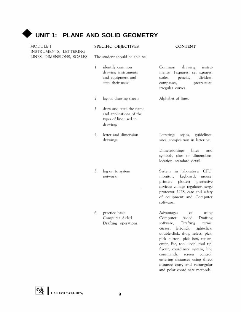
◆ UNIT 1: PLANE AND SOLID GEOMETRYMODULE I INSTRUMENTS, LETTERING, LINES, DIMENSIONS, SCALES
SPECIFIC OBJECTIVES
The student should be able to:
1. identify commondrawing instrumentsand equipment andstate their uses;
2. layout drawing sheet;
3. draw and state the nameand applications of thetypes of line used indrawing;
4. letter and dimensiondrawings;
5. log on to systemnetwork;
6. practice basicComputer AidedDrafting operations.
CONTENT
Common drawing instru- ments: T-squares, set squares, scales, pencils, dividers, compasses, protractors, irregular curves.
Alphabet of lines.
Lettering: styles, guidelines, sizes, composition in lettering
Dimensioning: lines and symbols, sizes of dimensions, location, standard detail.
System in laboratory: CPU, monitor, keyboard, mouse, printer, plotter; protective devices: voltage regulator, serge protector, UPS; care and safety of equipment and Computer software..
Advantages of using Computer Aided Drafting software, Drafting terms: cursor, left-click, right-click, double-click, drag, select, pick, pick button, pick box, return, enter, Esc, tool, icon, tool tip, flyout, coordinate system, line commands, screen control, entering distances using direct distance entry and rectangular and polar coordinate methods.
CXC 13/O /SYLL 00/A1 9

MODULE I INSTRUMENTS, LETTERING, LINES, DIMENSIONS, SCALES CONT’D
MODULE II GEOMETRIC CONSTRUCTIONS
MODULE III CONSTRUCTION OF POLYGONS
SPECIFIC OBJECTIVES
The student should be able to:
1. bisect straight lines,arcs and angles;
2. draw perpendicular to agiven line, at a point onthe line or from a pointoutside the line;
3. draw a line parallel to agiven line.
4. divide straight lines andangles geometrically;
5. copy any given angle.
The student should be able to:
1. construct triangles given:-three sides; two anglesand one side; two sidesand included angle;perimeter and proportionof sides; altitude and baseangles; perimeter andbase angles;
2. construct a square giventhe length of one sideand the diagonal;
CONTENT
adjusting drawing limits, drawing lines, drawing circles, object snap, power snap, dimensioning. Saving and printing drawing.
Geometrical terms: bisector, angle, perpendicular, parallel, arc. Angles: definitions and types; acute, right, obtuse, straight line.
Characteristics of lines in drawing.
Proportional division of lines and angles.
Triangles: definitions and parts of. Types of triangles: right angled, equilateral, isosceles, scalene, ambiguous case. Necessary data for the construction of triangles. Methods of construction of various types of triangles.
Quadrilaterals: squares, rectangles, parallelograms
CXC 13/O /SYLL 00/A1 10
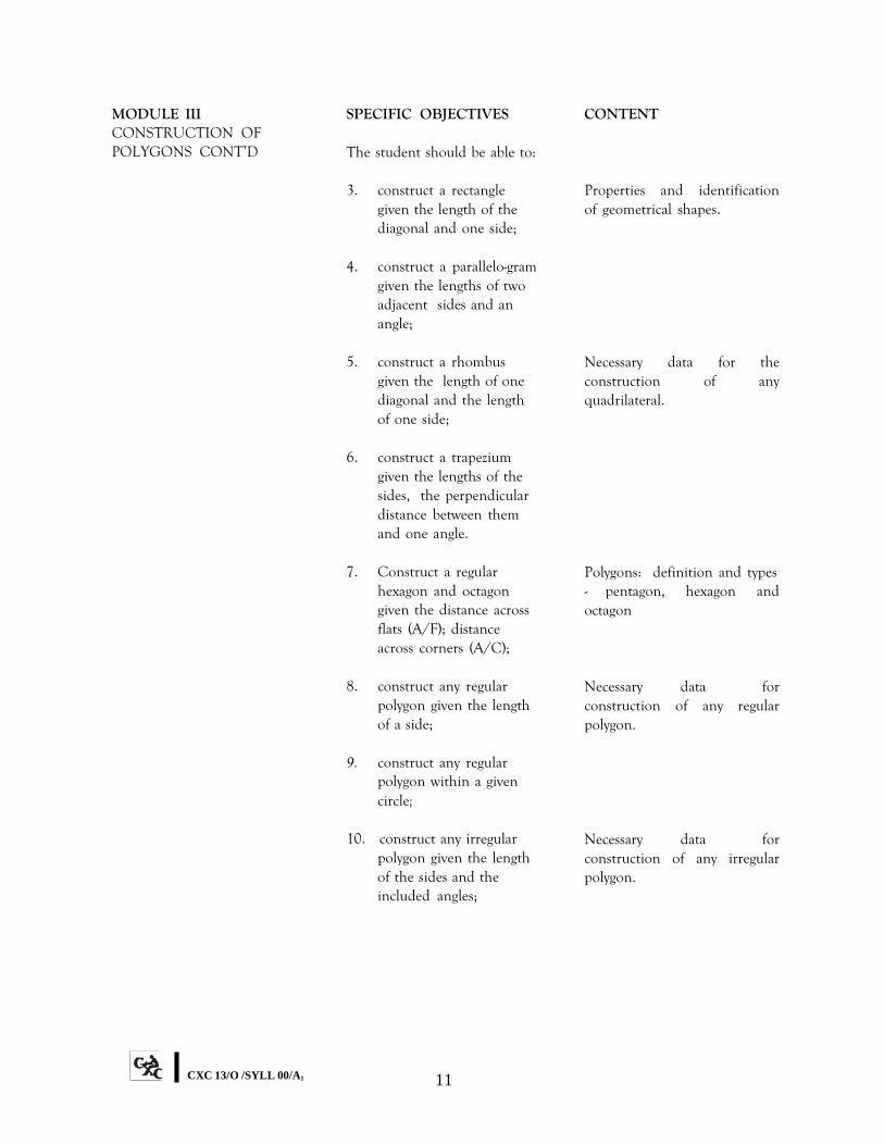
MODULE III CONSTRUCTION OF POLYGONS CONT’D
SPECIFIC OBJECTIVES
The student should be able to:
3. construct a rectanglegiven the length of thediagonal and one side;
4. construct a parallelo-gramgiven the lengths of twoadjacent sides and anangle;
5. construct a rhombusgiven the length of onediagonal and the lengthof one side;
6. construct a trapeziumgiven the lengths of thesides, the perpendiculardistance between themand one angle.
7. Construct a regularhexagon and octagongiven the distance acrossflats (A/F); distanceacross corners (A/C);
8. construct any regularpolygon given the lengthof a side;
9. construct any regularpolygon within a givencircle;
10. construct any irregularpolygon given the lengthof the sides and theincluded angles;
CONTENT
Properties and identification of geometrical shapes.
Necessary data for the construction of any quadrilateral.
Polygons: definition and types - pentagon, hexagon and octagon
Necessary data for construction of any regular polygon.
Necessary data for construction of any irregular polygon.
CXC 13/O /SYLL 00/A1 11
MODULE IV CIRCLES, ARCS, CURVES AND TANGENTS
SPECIFIC OBJECTIVES
The student should be able to:
1. construct circles givendiameter or circum- ference;
2. construct a circle to passthrough - three givenpoints; a fixed point andtouching a line at a givenpoint; two given pointsand touching a given line;two given points andtouching a given circle;
3. draw three circles whichtouch each other giventhe positions of the threecentres;
4. construct the inscribed,circumscribed andescribed circles of anygiven triangle and anygiven regular polygon.
5. inscribe the largest squarewithin a triangle with oneside lying on a side of thetriangle;
6. draw arcs tangential totwo straight lines atacute, right and obtuseangles;
CONTENT
Definition of a circle: parts of a circle - diameter, radius, arc, chord, quadrant. Properties of a circle.
Construction of circles.
Relationship of the bisectors of the interior angles to the inscribed circle.
Definition of inscribed, circumscribed and escribed circles.
Relationship between the perpendicular bisector of a line and the circumscribed circle.
Arcs and their relationship to the circle.
CXC 13/O /SYLL 00/A1 12
MODULE IV CIRCLES, ARCS, CURVES AND TANGENTS CONT’D
MODULE V EQUIVALENT AREAS; REDUCING AND ENLARGING PLANE FIGURES
SPECIFIC OBJECTIVES
The student should be able to:
7. draw tangents to - a circleat a given point on thecircumference; a circlefrom any given pointoutside of the circle; twogiven circles;
8. construct the commoninternal and externaltangents to two givencircles;
9. draw an arc tangential totwo given circles ofdifferent radii.
The student should be able to:
1. construct rectangles equalin area to triangles;squares equal in area torectangles and triangles;triangles equal in area toquadrilaterals andpolygons; squares equalin area to quadrilateralsand polygons;
2. determine areas of planefigures graphically;
3. divide triangles andpolygons into a numberof equal parts by drawinglines parallel to one side;
4. reduce and enlarge planefigures by linear measure- ments or ratio of sides;ratio of areas;
CONTENT
Definition of a tangent. Tangencies of circles, arcs and straight lines and their practical applications.
Internal and external tangents and their applications. Centres and tangency points.
Areas of triangles, squares, rectangles, quadrilaterals, and polygons.
Graphical determination of areas of laminae and combined plane figures.
Similar triangles and pro- portional figures.
Principles involved in reducing and enlarging areas of figures.
CXC 13/O /SYLL 00/A1 13

MODULE VI LOCI
MODULE VII PICTORIAL DRAWINGS
SPECIFIC OBJECTIVES The student should be able to:
1. draw an ellipse by the foci,
trammel, concentric circles and rectangular methods; and construct normal and tangent at a point on the curve;
2. draw by the focus method:
parabola; hyperbola; 3. draw the involute of a
square and a circle; 4. plot and trace the loci of
given points; 5. plot and trace the loci in a
simple crank mechanism; 6. draw an Archimedean
Spiral; 7. draw cycloidal curves.
The student should be able to:
1. draw isometric, oblique
and 1-and 2-point perspective drawings of geometric solids and simple models.
CONTENT Conic sections – relation-ships Ellipse: definitions and properties. The ellipse as loci of a moving point. Methods of construction of the ellipse. Parts of the ellipse: major and minor axes, directrix, vertices, focus.
Parabola and hyperbola: definition and properties. Methods of construction of the parabola and hyperbola. Parts of parabola and hyperbola: vertices, directrix, focus, ordinate.
Involute of a circle.
Simple loci problems with practical applications.
Archimedean Spiral. Parts of a spiral: pole, radius, vector, convolution.
Cycloidal curves and their applications.
Principles of pictorial drawings - isometric, oblique and pers- pective geometric solids: cones, prisms, pyramids, cylinders, simple models, blocks, isometric circles. Free hand pictorial sketches.
CXC 13/O /SYLL 00/A1 14
MODULE VII PICTORIAL DRAWINGS CONT'D
MODULE VIII ORTHOGRAPHIC PROJECTION
MODULE IX AUXILIARY PROJECTIONS
SPECIFIC OBJECTIVES The student should be able to:
1. draw orthographic
projections of geometric solids and simple models using First angle or Third Angle projection;
The student should be able to:
1. draw primary auxiliary
views by projection; 2. determine the true
lengths of straight lines by revolution and auxiliary methods;
3. determine true shapes of
laminae by auxiliary projections;
4. determine the true shapes
of sectioned surfaces of geometric solids;
5. construct curves of
interpenetration of geometric solids with their axes in the same plane;
CONTENT Using Drawing Aids: grid, snap, isoplane settings.
Planes of projection: horizontal and vertical planes. Plans and elevations.
Free hand orthographic
Auxiliary planes of projection - oblique planes inclined to both horizontal and vertical planes.
Straight lines and laminae inclined to both horizontal and vertical planes.
Cones, cylinders, prisms and pyramids.
Solids with axes in the same plane, cylinder/cylinder, prism/prism, prism/cylinder.
CXC 13/O /SYLL 00/A1 15

MODULE X SURFACE DEVELOPMENTS
MODULE XI HELICAL CURVES
SPECIFIC OBJECTIVES The student should be able to:
1. draw surface
developments of right geometric solids;
2. draw surface develop-
ments of sectioned right geometric solids;
The student should be able to:
1. draw helical spring of
circular cross-section; 2. construct a single helical
curve on a cylinder;
CONTENT Cones, cylinders, prisms, pyramids.
Frusta of cones, pyramids, prisms, cylinders and sheet metal joints, bends, knees.
Helix curve, pitch, lead.
CXC 13/O /SYLL 00/A1 16
◆ UNIT 2: BUILDING DRAWIN G
MODULE I BUILDING CODES AND MATERIALS
MODULE II SITE WORK
SPECIFIC OBJECTIVES
The student should be able to:
1. demonstrate theapplication of Buildingcodes as they apply tostandard buildingdrawing procedures;
2. prepare a drawing sheet;
3. demonstrate standardarchitectural practice;
4. prepare drawings to givenscales;
5. produce 2D and 3D solidmodel drawings of abuilding or itscomponents.
The student should be able to:
1. prepare working plansof building sites;
2. prepare site plans;
CONTENT
Building code regulations, for example, set backs, road sizes, verge, water zones.
Borders, title blocks
Standard drawing practice, for example, lines weight, letter- ing, symbols, conventions.
Sketching in proportion, working drawings to scale.
Drawing Aids, drawing construction lines (c-lines) using cross, parallel with full distance, drawing outline, inserting dimension, hatching, using mirror copy, saving & printing .
Importance of site investi- gation. Common site clearance practices: demolish- ing, salvaging, cutting, burning, earth-moving and disposing.
Factors important to site layout: slope, layout of land, drainage, sewer disposal, fencing, locating boundaries, building regulations for site layout. Components of site plans. Elementary intro- duction to sub-soils.
CXC 13/O /SYLL 00/A1 17

MODULE III FOUNDATIONS
MODULE IV FLOOR PLANS AND ELEVATIONS
MODULE V FLOORS
SPECIFIC OBJECTIVES The student should be able to:
1. prepare simple working
drawings of foundation work;
2. prepare sketches for
concrete foundations of buildings;
3. prepare sketches for
simple reinforcement of foundation work;
4. prepare drawings of
common footings used in building construction;
5. draw foundation plans;
The student should be able to:
1. design and layout a
simple floor plan from given specifications;
2. make a freehand sketch
of a floor plan; 3. draw floor plans to given
scales; 4. draw elevations of
buildings; The student should be able to:
1. prepare drawings show-
ing various types of floor and floor section;
CONTENT Simple concrete foundations for level and sloping ground.
Simple reinforcement , ortho- graphic pictorial and freehand sketches
Instrument drawings/section details
Position of foundation wall, footing.
Orientation and relationship of rooms, positioning of walls, windows, doors, stairs, arches, bathroom and kitchen symbols. Linework, dimen- sioning annotation. Measur- ing to scale.
Projections and orientation, ground line, floor line, doors and windows in elevation, height of roof, fascia eave, rendering.
Solid, hollow and suspended ground floor, floor covering, for example, tiles, screed.
CXC 13/O /SYLL 00/A1 18
MODULE VI INTERNAL AND EXTERNAL WALLS AND FINISHING
MODULE VII ROOFS
SPECIFIC OBJECTIVES The student should be able to:
1. draw details of various
types of wall; 2. differentiate between
internal and external load bearing and non-load bearing walls;
3. draw detailed framed
timber partition; 4. make working drawings
of wall details; The student should be able to:
1. draw plan and elevations
of various types of roof and roof structure;
2. prepare working drawings
of roof anchorage systems; 3. prepare a working drawing
of a roof showing truss details;
4. prepare working drawings
showing open and closed eaves;
CONTENT Stone rubble walls Concrete block walls Brick walls Composite walls Internal and external rendering; sectional details
Load and non-load bearing walls constructions in blocks and timber.
Treatment of openings in wall.
Plastering to walls and ceilings. Internal and external renderings. Sectional details.
Common types of roofs found in the region. Roof terms: ridgeplate, common rafters, hip rafters, valley rafters. Flat roofs in timber and their coverings, gable-end roofs. Pitched roof construction with various coverings. Treatment of gutters, parapets and ventpipes.
Methods of anchorage, hurricane clips/straps, bolts
Simple contemporary timber trusses.
Eave details, dimensioning and annotations.
CXC 13/O /SYLL 00/A1 19

MODULE VIII DOORS AND WINDOWS
MODULE IX STAIRWAYS
MODULE X SECTIONS
SPECIFIC OBJECTIVES The student should be able to:
1. prepare drawings
showing various types of door and window and their fittings;
2. draw a detailed section of
a sliding window in a masonry wall;
3. prepare typical sectional
drawings to show door and window details;
The student should be able to:
1. draw stairs and calculate
risers from given heights; 2. prepare drawings of
common inside stairway; 3. prepare a sectional
working drawing of a straight flight staircase;
4. prepare a detailed
drawing of the parts of a step;
The student should be able to:
1. prepare full sectional drawings
of single-storey buildings;
CONTENT Internal and external doors with linings and frames. Common types of windows.
Horizontal and vertical sliding windows.
Window casements, iron- mongery and louvres. Positioning of hinges and locks.
Principles of construction of straight flight stairs – both timber and simple reinforced concrete.
Using principles of ortho- graphic projection: found- ation, floors, walls, roofs.
CXC 13/O /SYLL 00/A1 20

◆ UNIT 3: MECHANICAL ENGINEERING DRAWING
MODULE I PREPARATION OF DRAWING SHEET
SPECIFIC OBJECTIVES CONTENT
The student should be able to:
1. prepare drawing sheet with appropriate title block.
B.S. 308 1984 parts 1 & 2; Engineering Drawing Office Practice - PD 7308; ISO 9000; Title of Drawing, Scale, Date of Drawing, Name of Draftsman, Drawing number, Revisions, Symbol of Projection, Lettering; Size of Drawing Sheets, Use of Guidelines.
MODULE II ORTHOGRAPHIC PROJECTION
The student should be able to:
1. draw orthographic views in first-angle or third-angle projection of simple machine parts and components;
2. use machining symbols on machine parts and components;
3. prepare scaled
orthographic views in first-angle or third- angle projection of simple machine parts and components;
Orthographic views in First or Third Angle Projection of vee blocks, plummer block, tool holders, tool post, connecting rod, pulley frame, pulleys, pulley yoke, lever bracket, machine vice body, shaft bearing, angle plate base, pivot block, bearing block, axle support.
Machined surfaces.
Scales: Reduction 1:2; 1:5; 1:25; 1:50; 1:100:, 1:500. Scale: Enlargement: 2:1, 5:1, 10:1, 25:1, 50:1, 100:1. Diagonal scale. Indicate scale used.
CXC 13/O /SYLL 00/A1 21
MODULE II SPECIFIC OBJECTIVES CONTENT ORTHOGRAPHIC PROJECTION CONT’D The student should be able to:
Drawing construction lines (c- lines) using cross, parallel with full distance, drawing outline, inserting dimension; mirror copy drawing, inserting angle dimension, drawing centre lines, drawing and dimension- ing fillets & chamfer, drawing tangent lines, break objects, hatching, surface texture symbols, leader lines. hidden detail lines, use of shaft generator, saving & printing drawing.
MODULE III ENGINEERING CONVENTIONS
The student should be able to:
1. apply conventional representations for machine parts, components;
2. dimension drawings;
3. apply conventional representation of welding and brazing symbols on fabricated machine parts and components.
Conventional representation of bearings, metric screw thread, shafts, springs, gears, knurl, flat on round, square, lap, countersink, counterbore, spot face, chamfer, bevel, tubular sections.
Stop (Extension) lines, dimension lines, arrowheads, leaders, overall dimensions, chain dimensioning, linear dimensioning, dual dimension- ing, angular dimensioning, arrangement of dimensions, toleranced dimensions, radius, diameter, circles, arcs, metric screw threads.
Welding and brazing symbols.
CXC 13/O /SYLL 00/A1 22
MODULE IV SECTIONS
SPECIFIC OBJECTIVES
The student should be able to:
1. prepare sectional drawings of simple machines, machine parts and com- ponents;
CONTENT
Types of sections: full, half, part, off-set, revolved, removed, local, sectional plan and elevations of vee block, plummer block, connecting rod, pulleys, lever bracket, machine vice body, shaft bearing, angle base plate, support block, support arm, support plate, brackets, jig body, shaper quadrant, tension block, bearing block, lathe tool post, link connector, com- pound rest, crank;
MODULE V ENGINEERING FASTENERS
The student should be able to:
1. make orthographic drawings and free- hand sketches of engineering fasteners;
Engineering fasteners: Tem- porary fasteners: nuts and bolts, screws, studs, cotters, locknuts, slotted nuts, castle nut, self-locking nut, spring washers, saddle keys, round keys, feather keys, parallel keys, taper keys, woodruff keys, split pins; Permanent fasteners: rivets, conventional representation of welds, and brazings: fillet, vee, butt, spot. Indication of direction, site and location of weld.
MODULE VI ASSEMBLY DRAWINGS
The student should be able to:
1. draw plan and elevations in first- angle or third-angle projection of assembled machine parts and components;
Assemblies of shaft and pulleys, casters, jigs and fixtures, machine and bench vices, bearing assemblies, universal couplings, lathe steady, pulley and hook, shaft block and bearing, tool supports and
CXC 13/O /SYLL 00/A1 23
MODULE VI ASSEMBLY DRAWINGS CONT’D
SPECIFIC OBJECTIVES
The student should be able to:
2. Draw sectional plans and elevations of assembled machine parts;
3. Read and prepare working drawings of machine parts and components;
CONTENT
holders, lathe tail stock, valve link connector, connecting rod and bearing, screw jack, scribing block, clamping devices, vee block and clamp, crank and pin, footstep bearing, clapper box, eccentrics, tool rest, pipe vice, swivel.
Parts list given machine components showing Part. No., Name of Part, Number required, Material, Remarks, balloon referencing.
4. Prepare parts list of machine components.
MODULE VII SKETCHING
The student should be able to:
1. make freehand sketches of engineering components;
2. produce 3D solid model
drawing. of engineering components.
Sketching of engineering features using standard graphic symbols, sectional assemblies;
Shaped blocks, chisels, punches, nuts and bolts, hammers, saws, vee block, clamps, mallets, anvil, lathe tools, drill bits, taps and dies, reamers, welded joints, lathe tail stock, lathe centres, spanners, wrenches, tri-square, snips, stakes, hand groover, rivet snap, tap wrench.
Using drawing aids: grid, snap, isoplane setting.
CXC 13/O /SYLL 00/A1 24
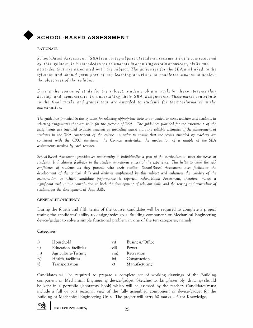
◆ SCHOOL-BASED ASSESSMENT
RATIONALE
Sc h o o l - Ba s e d A s s e s s m e n t ( S BA ) i s a n i n t e g r a l p a r t o f s t u d e n t a s s e s s m e n t i n t h e co u r s eco v e r ed b y t h i s s yl l a b u s . It i s i n t en d ed t o a s s i s t s t u d en t s i n ac q ui r i n g c e r t a i n kn ow l e d g e, s k i l l s an d at t i t ud e s t hat ar e as s oc i at e d w i t h t he s ub j e c t . T he ac t i v i t i e s f or t he SB A a r e l i n k e d t o t h e s y l l a b u s a n d s h o u l d f o r m p a r t o f t h e l e a r n i n g a c t i v i t i e s t o e n a b l e th e s tu d e n t to a c h i e v e th e o b j e c t i v e s o f th e s y l l a b u s . Du r i n g t h e c o u r s e o f s t u d y f o r t h e s u b j e c t , s t u d e n t s o b t a i n ma r k s f o r t h e co m p e t en ce t h ey d ev e l o p a n d d em o n s t r a t e i n u n d er t a k i n g t h e i r S B A a s s i g n m en t s . T h e s e ma r k s c o n t r i b u t e t o t h e f i n a l ma r k s a n d g r a d e s t h a t a r e a w a r d e d t o s t u d e n t s f o r t h e i r pe r f or m an c e in t h e e x a m in a t io n . The guidelines provided in this syllabus for selecting appropriate tasks are intended to assist teachers and students in selecting assignments that are valid for the purpose of SBA. The guidelines provided for the assessment of the assignments are intended to assist teachers in awarding marks that are reliable estimates of the achievement of students in the SBA component of the course. In order to ensure that the scores awarded by teachers are consistent with the CXC standards, the Council undertakes the moderation of a sample of the SBA assignments marked by each teacher.
School-Based Assessment provides an opportunity to individualise a part of the curriculum to meet the needs of students. It facilitates feedback to the student at various stages of the experience. This helps to build the self- confidence of students as they proceed with their studies. School-Based Assessment also facilitates the development of the critical skills and abilities emphasised by this subject and enhances the validity of the examination on which candidate performance is reported. School-Based Assessment, therefore, makes a significant and unique contribution to both the development of relevant skills and the testing and rewarding of students for the development of those skills.
GENERAL PROFICIENCY
During the fourth and fifth terms of the course, candidates will be required to complete a project testing the candidates’ ability to design/redesign a Building component or Mechanical Engineering device/gadget to solve a simple functional problem in one of the ten categories, namely:
Categories
i) Household vi) Business/Office ii) Education facilities vii) Power iii) Agriculture/Fishing viii) Recreation iv) Health facilities ix) Construction v) Transportation x) Manufacturing
Candidates will be required to prepare a complete set of working drawings of the Building component or Mechanical Engineering device/gadget. Sketches, working/assembly drawings should be kept in a portfolio (laboratory book) which will be assessed by the teacher. Candidates must include a full or part sectional view of the fully assembled component or device/gadget for the Building or Mechanical Engineering Unit. The project will carry 60 marks – 6 for Knowledge,
CXC 13/O /SYLL 00/A1 25

24 for Application and 30 for Practical Ability and will account for 20% of the composite score (See page 4 of this document for detailed criteria and mark scheme).
NB: Th e t e a c h e r s h o u l d p r e p a r e ca n d i d a t e s fo r t h e d ra w in g p ro je c t b y d i sc u ssin g w it h th e m th e s ta g e s in t h e d e si g n p ro c e ss : re c o g n i t i o n o f n e e d ; d e f i n i t i o n o f p ro b l e m ; i l lu st r a t io n o f v a r io u s a sp e c t s o f so lu t io n ; se le c t io n o f b e st so lu t io n ; e v a lu a t io n o f se l e c t e d so l u t io n ; an d pr e s e n t at i on of c hos e n s ol ut i on .
Th e d r a wi n g p r o j e c t m u s t b e d o n e i n i t s e n t i r e ty i n th e c l a s s ro o m / l a b o ra to ry . S i nc e t h i s p r o j e c t i s p a r t o f Sc h o o l - Ba s e d A s s e s s m e n t , i t m u s t b e d o n e u n d e r t h e gu i d a n c e o f t h e t e a c h e r b u t m u s t b e t h e c a n d i d a t e ’ s o w n w o r k .
Ca n d i d a t e s w h o o p t t o u s e t h e T r a d i t i o n a l D r a w i n g M e t h o d f o r P a p e r 0 2 a n d Pa pe r 0 3 m ay , n e v e r t he l e s s , opt t o do t he S B A dr aw i n g pr o j e c t us i n g t he C om put e r Ai d e d D r a f t i n g m e t h o d / a p p l i c a t i o n .
◆ RECOMMENDED MINIMUM EQUIPMENT/MATERIAL FOR TECHNICAL DRAWING SYLLABUS
TRADITIONAL DRAWING METHOD (For a Class of 20)
Any suitable classroom can be converted into a Drawing Room with the addition of Drawing Boards.
EQUIPMENT QUANTITY
1. Drawing boards 20 OR
Dual drawing desks 10 OR
Drawing tables 20 2. Half imperial tee-squares 20 3. Pair of set squares 20 4. Protractors, scales and french curves 20 5. Pair of drawing clips 20 6. Set of drawing instruments 20
In addition, students will be required to have the following:
(a) A hand towel or cheese cloth; (b) A good eraser; (c) Pencil – grades HB, F, H 2H.
CXC 13/O /SYLL 00/A1 26
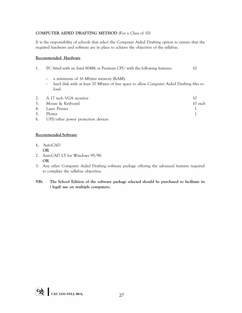
COMPUTER AIDED DRAFTING METHOD (For a Class of 10)
It is the responsibility of schools that select the Computer Aided Drafting option to ensure that the required hardware and software are in place to achieve the objectives of the syllabus.
Recommended Hardware
1. PC fitted with an Intel 80486 or Pentium CPU with the following features: 10
- a minimum of 16 Mbytes memory (RAM); - hard disk with at least 70 Mbytes of free space to allow Computer Aided Drafting files to
load.
2. A 17 inch VGA monitor 10 3. Mouse & Keyboard 10 each 4. Laser Printer 1 5. Plotter 1 6. UPS/other power protection devices
Recommended Software
1. AutoCAD OR
2. AutoCAD LT for Windows 95/98. OR
3. Any other Computer Aided Drafting software package offering the advanced features required to complete the syllabus objectives.
NB: The School Edition of the software package selected should be purchased to facilitate its
( legal) use on multiple computers.
CXC 13/O /SYLL 00/A1 27
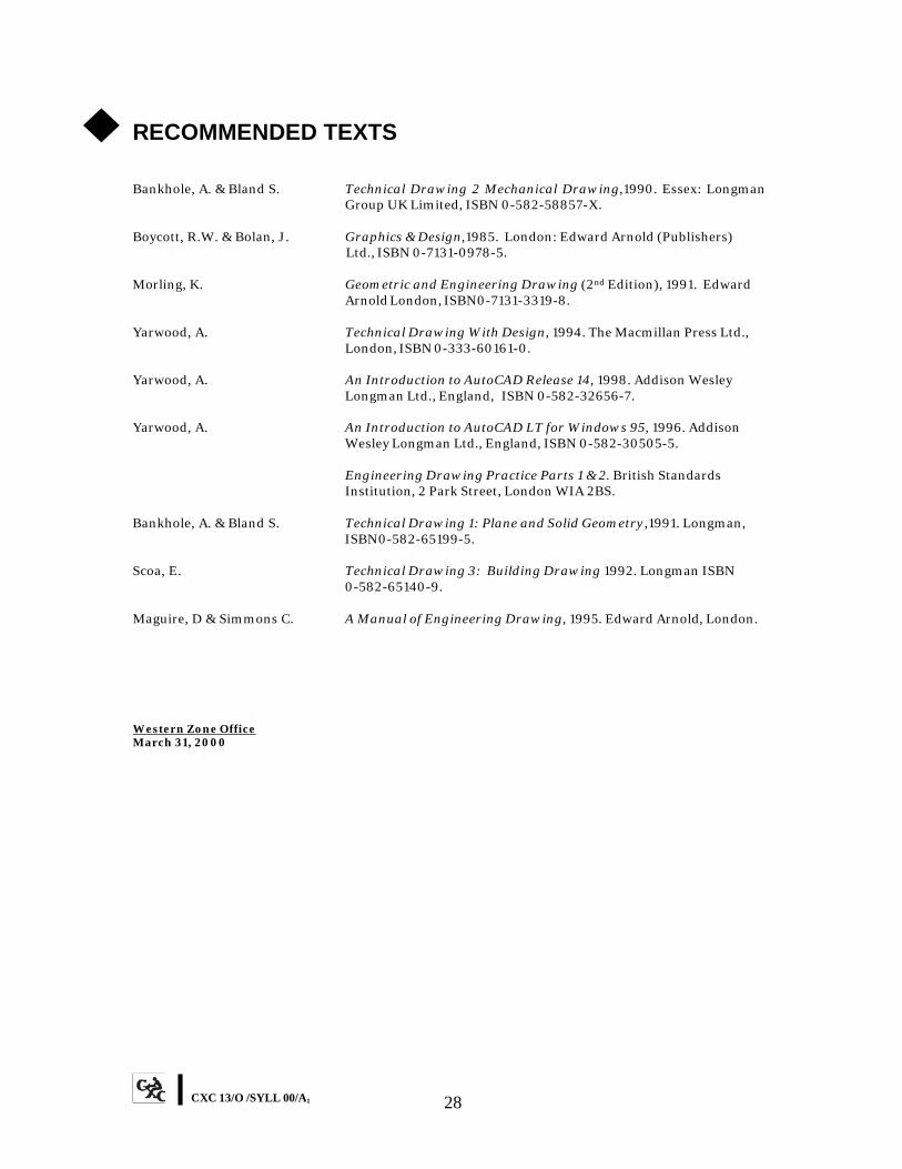
◆ RECOMMENDED TEXTS
Bankhole, A. & Bland S. Technical Drawing 2 Mechanical Drawing,1990. Essex: Longman Group UK Limited, ISBN 0-582-58857-X.
Boycott, R.W. & Bolan, J. Graphics & Design,1985. London: Edward Arnold (Publishers) Ltd., ISBN 0-7131-0978-5.
Morling, K. Geometric and Engineering Drawing (2nd Edition), 1991. Edward Arnold London, ISBN0-7131-3319-8.
Yarwood, A. Technical Drawing With Design, 1994. The Macmillan Press Ltd., London, ISBN 0-333-60161-0.
Yarwood, A. An Introduction to AutoCAD Release 14, 1998. Addison Wesley Longman Ltd., England, ISBN 0-582-32656-7.
Yarwood, A. An Introduction to AutoCAD LT for Windows 95, 1996. Addison Wesley Longman Ltd., England, ISBN 0-582-30505-5.
Engineering Drawing Practice Parts 1 & 2. British Standards Institution, 2 Park Street, London WIA 2BS.
Bankhole, A. & Bland S. Technical Drawing 1: Plane and Solid Geometry,1991. Longman, ISBN0-582-65199-5.
Scoa, E. Technical Drawing 3: Building Drawing 1992. Longman ISBN 0-582-65140-9.
Maguire, D & Simmons C. A Manual of Engineering Drawing, 1995. Edward Arnold, London.
Western Zone Office March 31, 2000
CXC 13/O /SYLL 00/A1 28
29 C
XC
13/O /SY
LL 00/A1
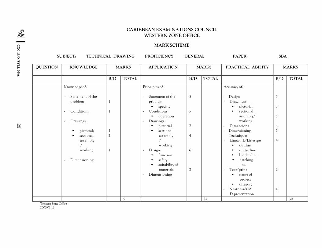
CARIBBEAN EXAMINATIONS COUNCIL WESTERN ZONE OFFICE
MARK SCHEME
SUBJECT: TECHNICAL DRAWING PROFICIENCY: GENERAL PAPER: SBA
QUESTION KNOWLEDGE MARKS APPLICATION MARKS PRACTICAL ABILITY MARKS
B/D TOTAL B/D TOTAL B/D TOTAL
Knowledge of:
- Statement of the problem
- Conditions
- Drawings:
• pictorial; • sectional
assembly/ working
- Dimensioning
1
1
1 2
1
Principles of :
- Statement of the problem • specific
- Conditions • operation
- Drawings: • pictorial • sectional
assembly/ working
- Design: • function • safety • suitability of
materials - Dimensioning
5
5
2
4
6
2
Accuracy of:
- Design - Drawings:
• pictorial • sectional
assembly/ working
- Dimensions - Dimensioning
Techniques - Linework/Linetype
• outline • centre line • hidden line • hatching
line - Text/print
• name of project
• category - Neatness/CA
D presentation
6
3
5
4 2
4
2
4
6 24 30 Western Zone Office 2005-02-18