Embed Size (px)
Citation preview
IEEE TRANSACTIONS ON PROFESSIONAL COMMUNICATION. VOL. PC-20, NO. 4, DECEMBER 1977 239
Technical Drawings and Illustrations
GEORGE A. MAGNAN
Abstract—Technical graphics originated with the simple need for instructional drawings, but has expanded to include a large variety of applications, materials, processes, and techniques. Engineers and scientists who must frequently communicate complex technical concepts should have a sufficient knowledge of the various types of artwork and methods of preparation that they can plan, direct, and participate in preparing their technical graphics. The types of technical publications produced by most technical organizations are described; guidance toward planning their illustrative content is offered; and a number of sources for visual infonnation are suggested.
T H E C O M M U N I C A T I O N S G A P
IN American industry a vast "communications gap" currently wastes huge sums of money annually, causes delays in
carrying out vital projects, and loses companies priceless business opportunities. This communications gap is largely due to the exponential growth of new, diverse, and overlapping, technologies, each generating its own special body of knowledge. It has become increasingly difficult to communicate this knowledge to others because of the rate at which it is accumulating.
During the last two decades there has been a growing comprehension of this problem, which has been reflected in a great increase in the internal efforts of most large corporations to bridge the gap. The efforts have been mainly through accelerating information interchanges between groups who must work together within the parameters of complex, technically interrelated programs and projects, but who find it increasingly difficult because of the vertical specializations of their separate fields and the limitations of the very languages that are involved. Many engineers, in particular, are finding it difficult to understand each other or to communicate their messages to others simply as a result of the accretion of "jargon"-the special terminology applying only to a particular field, which people not in that field cannot comprehend without an interpreter.
Continuing growth of vertical specialization in technology creates new problems as we reorient ourselves to a second industrial revolution-that of the computer-which frees man from much of his formerly necessary mental labor and thus multiplies his intellectual capacities. As Marshall McLuhan points out, in our age of "electric technology," the range of man's interests, far from shrinking to some infinity-point of overspecialism, is becoming forced by the imperatives of the new age to broaden into a total process of learning and knowing. "This means," says McLuhan, "that all forms of employ-
Reprinted with permission from Using Technical Art; An industry
Guide, Chapter 1, copyright 1970 by John Wiley & Sons, Inc., New York.
The author is an Editor for St. Regis Publications and Syndicate Magazines, New York; his address is 226 Pasqual Ave., Ventura, CA 93003, (805) 647-7977.
ment become 'paid learning,' and all forms of wealth result from the movement of information." (Italics added.)
A significant element in this "movement of information" to which McLuhan refers is the visual aid. Graphic pictorial types of information are recognized and increasingly used for their vital communication value, both as unique media in their own right and for their usefulness in supplementing the written and spoken word.
V I S U A L A I D S I N A M E R I C A N I N D U S T R Y
This reliance on visual media has not always been so; in fact, just prior to World War II the use of pictorials in industry's technical communication was limited to blueprints and the few perspective-type technical illustrations grudgingly deemed necessary for use by mechanics and technicians in operating and servicing equipment. Instruction booklets containing diagrams and illustrations, like all promotional graphics, literature, and advertising, were mostly outside the sphere of interest of manufacturers, who wanted nothing but product-making operations going on within their gates. There were no publications groups, reproductions departments, or technical artists. As a consequence, the business of internal as well as external generation of technical and promotional information was an "orphan" left to the company's advertising agency when it was considered worthy of bothering with at all.
This situation changed irrevocably with the advent of World War II . Industry, forced overnight into greatly expanding its operations and making new, complex products, found technical illustrations indispensable as visual aids in training unskilled production workers, providing a communications "bridge" between diverse employees, departments, executives, and vendors, and establishing for the first time a complete, thorough, and accurate documentation in the form of technical manuals needed to service, operate, and repair military equipment in the field.
Once introduced within industry, new concepts and uses for technical graphics flourished. Technical illustrations were discovered to be useful not only as production aids and handbook illustrations but as instruments of communication, enabling nontechnical people to grasp new design concepts, unusual and complex principles, and advanced planning proposals generated by research scientists, designers, and engineers.
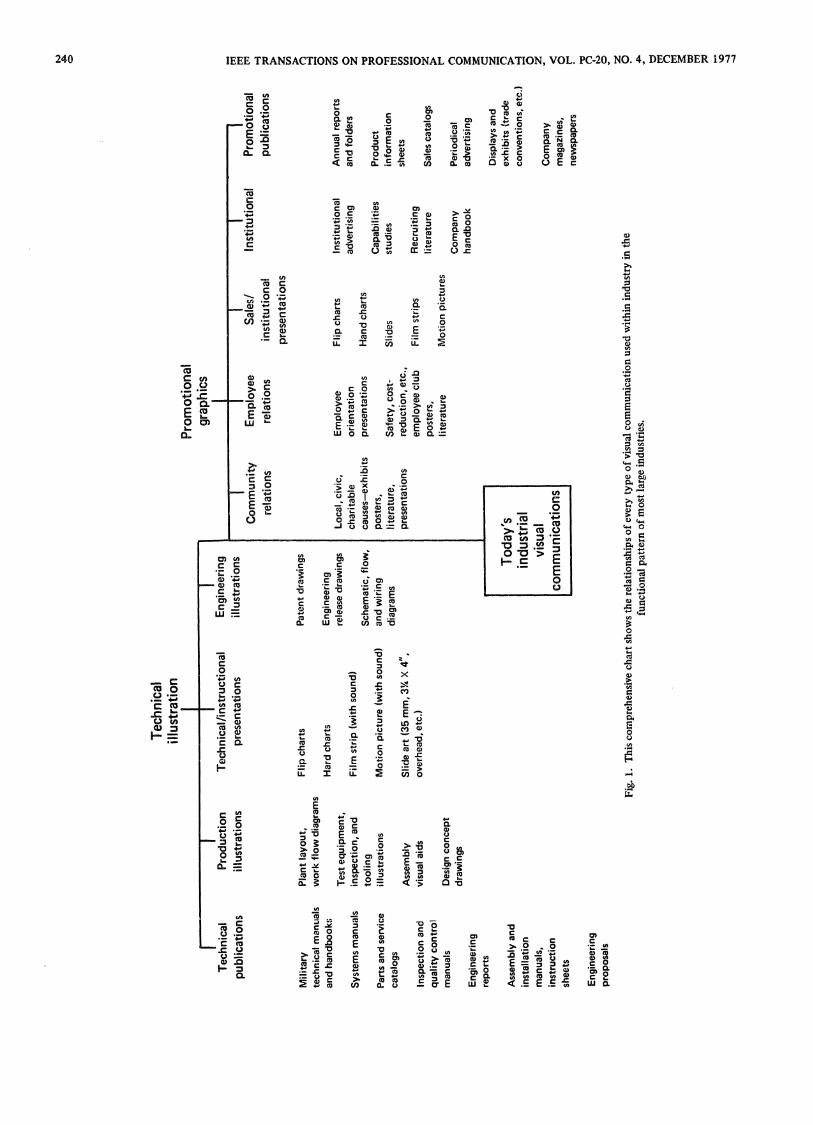
Today, although technical illustrations continue to serve their original, useful role as adjuncts to production and descriptive literature, something new has been added: a sophisticated variety of visual communication techniques used as internal aids in research and development projects and in promoting product development from their earliest design stages to acceptance through customer-oriented presentations and proposals (see Fig. 1).
Tech
nica
l ill
ustr
atio
n
Tec
hnic
al
publ
icat
ions
Mili
tary
te
chni
cal
man
uals
an
d ha
ndbo
ok;;
Syst
ems
man
uals
Parts
and
ser
vice
ca
talo
gs
Insp
ectio
n an
d qu
ality
con
trol
m
anua
ls
Engi
neer
ing
repo
rts
Asse
mbl
y an
d in
stal
latio
n m
anua
ls,
inst
ruct
ion
shee
ts
Engi
neer
ing
prop
osal
s
Pro
du
ctio
n il
lust
rati
ons
Plan
t la
yout
, w
ork
flow
dia
gram
s
Test
equ
ipm
ent,
insp
ectio
n, a
nd
tool
ing
illus
trat
ions
Asse
mbl
y vi
sual
aid
s
Desi
gn c
once
pt
draw
ings
Tec
hn
ical
/in
stru
ctio
nal
p
rese
nta
tio
ns
Eng
inee
ring
il
lust
rati
ons
Pro
mot
iona
l gr
aphi
cs
Co
mm
un
ity
Em
plo
yee
S
ales
/ In
stit
utio
nal
Toda
y's
indu
stri
al
visu
al
com
mun
icat
ions
Fig.
1.
Thi
s com
preh
ensi
ve c
hart
sho
ws
the
rela
tions
hips
of
ever
y ty
pe o
f vi
sual
com
mun
icat
ion
used
with
in in
dust
ry in
the
fu
nctio
nal
patt
ern
of m
ost
larg
e in
dust
ries
.
Pro
mo
tio
nal
rela
tion
s re
lati
ons
inst
itut
iona
l pu
blic
atio
ns
pre
sen
tati
on
s
Flip
cha
rts
Pate
nt d
raw
ings
Har
d ch
arts
En
gine
erin
g re
leas
e dr
awin
gs
Loca
l, ci
vic.
Em
ploy
ee
Flip
cha
rts
Inst
itutio
nal
Ann
ual
repo
rts
Film
str
ip (
with
sou
nd)
char
itabl
e or
ient
atio
n ad
verti
sing
an
d fo
lder
s Sc
hem
atic
, flo
w.
caus
es—
exhi
bits
pr
esen
tatio
ns
Han
d ch
arts
M
otio
n pi
ctur
e (w
ith s
ound
) an
d w
iring
po
ster
s,
Cap
abili
ties
Prod
uct
diag
ram
s lit
erat
ure,
Sa
fety
, cos
t-Sl
ides
st
udie
s in
form
atio
n Sl
ide
art
(35
mm
, 31Λ
X 4
",
pres
enta
tions
re
duct
ion,
etc
., sh
eets
over
head
, etc
.) em
ploy
ee c
lub
Film
stri
ps
Rec
ruiti
ng
over
head
, etc
.) po
ster
s.
liter
atur
e Sa
les
cata
logs
lit
erat
ure
Mot
ion
pict
ures
C
ompa
ny
Perio
dica
l ha
ndbo
ok
adve
rtisi
ng
Disp
lays
and
ex
hibi
ts (
trad
e co
nven
tions
, etc
.
Com
pany
m
agaz
ines
, ne
wsp
aper
s
240 IEEE TRANSACTIONS ON PROFESSIONAL COMMUNICATION, VOL. PC-20, NO. 4, DECEMBER 1977
MAGNAN: TECHNICAL DRAWINGS AND ILLUSTRATIONS 241
Technical briefings, meetings, and sessions of one kind or another are at an all-time high—especially those using well-prepared illustrations, diagrams, charts and graphs, and other visual aids. Improved graphic forms of communication appear in company reports, studies, and informational literature. They are designed to create interdisciplinary understanding among the technical people themselves and to build a bridge between the scientists and mostly nontechnical, company executives and top management, and also between the technical project planners and government and commercial customers. Vastly expanded use of audio-visual presentations of all kinds are another result of this communication effort. In addition, the attempt to maintain close managerial control through constant, detailed visibility of all facets of a company's operations-financial, production, research, development, etc.—requires putting all the facts into the best graphic form that can be readily assimilated.
In some highly concentrated areas of industry, all these diverse aims have evolved into major programs planned and carried out by graphic communications experts. In many medium-sized companies and practically ail the small ones, the average engineer, scientist, technical specialist, or executive is still left pretty much on his own to solve his problems of visual communications as they arise. In any case, he continues to face another growing problem of properly interpreting and demonstrating specialized facts concerning his projects in such a way that higher management, other internal collaborators, customers, and very often the general public as well can understand what he is doing and what he seeks to accomplish.
In this drive to disseminate information, visual aids are a powerful, effective ally, sometimes an all-important one. In a competitive situation the well-illustrated exposition very often wins over other proposals of equal technical merit but less well illustrated, simply because the former is better understood.
But there are a great many types of technical visual aids. What set of guidelines can be used? What are the criteria for intelligently determining what type of drawing or illustration will best fit each special situation?
W H A T W I L L C O M M U N I C A T E BEST?
There is one simple basic criterion. Pictures or drawings should be planned, the method of delineation selected, and the project carried through from start to finish on the basis of the question: What will communicate best? What type of visual can best be understood by the person who must use this information? Not:
What will look the handsomest? What is most convenient for the illustrator? What was the way it always has been done before?
Put yourself in the position of the user. How will he use the information being supplied? If he is a mechanic, for example, what type of diagram or illustration will he need to perform a certain maintenance operation? There he stands, wrenches in hand, looking through an opened access door at exposed machinery. Visualize him glancing at his repair manual, opened to the correct page. Does the spread contain all the information he needs to fix that equipment-pictures, text, and all-or
must he interrupt his work to leaf through the book to look up information on other pages? Are the part numbers on the drawing easily read, and do the arrows from them follow the simplest route to the parts shown, without crisscrossing other arrows or parts of the drawing? And most important of all, is the equipment drawn from the same viewing angle that he looks at it? He will have much more difficulty if, for instance, the only way to get at the parts is from underneath, but the illustration is what he would see looking down at the equipment. This common-sense injunction is violated much more often than one might think, since many manuals save on art time by drawing all views, without exception, to a single, standardized three-quarters upper view. Publications and art chiefs can count tangible savings from this standardization, but nobody knows how much time is lost in the field using these drawings which, essentially, have been made for the convenience of the illustrator-not the userl
For any type of visual communication to be really effective, there must be understanding between the three parties involved-the initiator (engineer, executive, or other person who generates the need to express his ideas visually), the illustrator (art director, draftsman, designer, illustrator, and others who translate the initiator's message into pictorial form), and the user (all those who need to understand the pictorial message in order to carry out their own work). Ideally, the visual concept flows from initiator to illustrator to user, with provision for feedback from user to initiator to gauge the merit of the concept and provide a basis for future experience. But this ideal communications flow does not exist much of the time, largely because of the nature of drawings themselves and the way they are interpreted.
There are five basic types of drawings used in industry:
Orthographies Two-dimensional engineering drawings Diagrams Functional, schematic, block, flow, wir
ing, etc.; charts and graphs Axonometrics Three-dimensional drawings lacking van
ishing-point perspective Perspectives Three-dimensional drawings with picture
planes diminishing to vanishing points with distance, as in nature
Photographs Continuous-tone camera pictures
The first type of drawing, orthographies, and to some extent the second, diagrams, are well understood by the initiator, if he is an engineer. They are equally well understood by the mechanical draftsman and most technical illustrators. Intercommunication here is smooth, even quite chummy. But the user—unless he is an experienced machinist who is well-trained at reading blueprints-finds the orthographic language hard to grasp. The nontechnical user-the salesman or marketing expert, for example-is left quite out in the cold if the blueprint is the only visual record of what something looks like.
Quite the opposite situation seems to exist when three-dimensional pictorials prevail. Whereas there is close rapport between the illustrator and the user, the engineer-initiator and the illustrator find it difficult to communicate because the initiator has been trained to express his thoughts in the orthographic, not the pictorial, language and generally does not understand why the illustrator wants to do certain things. Only
242 IEEE TRANSACTIONS ON PROFESSIONAL COMMUNICATION, VOL. PC-20, NO. 4, DECEMBER 1977
by better understanding the methods, uses, and practices involved in all the types of drawings used in industry can the initiator be in the position to select, specify, and direct visual media so as to provide the most efficient communication to users.
I N D U S T R Y ' S T E C H N I C A L L I T E R A T U R E
The engineer or project director who functions most effectively, with a record of success for his projects, is not likely to be narrow-minded, or one to hide his light or his company's under a bushel. Indeed, if there are any bushels involved, they are more likely to be the bushels of well-illustrated publications he generates to make sure of communicating essential information to everyone concerned, at all levels! Especially in the case of complex projects involving esoteric concepts which cut across a number of scientific disciplines, final success or failure can often be equated with his ability to get his message across to fellow workers, management, and the customer. Whether or not he, as project head, actually takes much part in the preparation of these publications, he is ultimately responsible for their success or lack of it in "breaking through" to his audience. Most, if not all, of this literature is technical and intended to convey strictly technical information. Broadly speaking, technical literature falls into the following categories.
Reports
(a) Internally used progress reports, for management visibility.
( b ) Regularly issued, periodic progress reports to a commercial customer, or to the military or government agency concerned if the project is under government contract. Most government agencies require these reports to be issued on a monthly and annual basis, as a contractual condition.
Proposals
Engineering proposals, design, feasibility studies, and manufacturing capability studies are most generally employed as a major device to bring in new business. They sum up the conclusions of scientists and engineers, either in brief, generally unsolicited, "idea" evaluations or, at the other extreme, in multivolume, detailed studies when the company is invited to compete for a major contract.
Writing and illustrating proposals is mainly done by technical publications people working directly with engineers, usually with some further collaboration of the company's sales or marketing group.
instruction Manuals
Instruction manuals may include under a single cover all technical information needed to use and maintain a product, or they may run to many separate manuals in the case of complex equipment such as aircraft. In general, the following are the types of handbook instruction involved:
(a) Operational manuals. (b ) Parts catalogs (illustrated parts breakdown). ( c ) Maintenance manuals—often including service bulletins,
testing, checkout, and support equipment manuals, and systems manuals.
(d ) Repair manuals.
Many handbooks, manuals, bulletins, etc. are usually generated on any major technical project for the purpose of instructing technicians, assemblers, etc. on correct assembly procedures, manufacturing planning sequences, tooling, etc.
Promotional Aids
In addition to literature of a strictly technical nature, the engineer is frequently called upon for written information, sketches, and data to be ultimately incorporated into promotional literature, such as product information sheets or bulletins, specifications, descriptive sales literature, promotional brochures, and sales catalogs.
There is a vast difference between the technical publications needed for firms working under defense contracts and those required to cover commercial products. A government survey has disclosed that the amount of documentation required to comply with military specifications is at least three times that used to supply needed technical data, instructions, etc. for comparable commercial items. A growing number of technical handbooks are devoted to the testing of military products. In one military system described under a government contract, the manuals on description, operation, maintenance, and training were only a third of the total manuals specified; another third consisted of illustrated parts manuals, and the remaining third covered nothing but operating test procedures.
In preparing all these informational aids, which usually are developed concurrently with the engineering project itself, the engineer is not generally left to his own devices. Although most companies encourage engineers to write technical papers, some prefer to leave the drafting of basic handbook texts to technicians who write under the engineer's supervision, and then send that text to the technical publications editor. However, there are some companies, both large and small, in which technical writing is done only by trained engineers in the belief that the writers need intimate knowledge of the technology in order to communicate it properly, and the only editing by publications people is a "polishing up." Most companies take a position between these extremes. But the trend is toward greater reliance upon the original design engineer to supply more complete and sophisticated documentation, as machines and products to be designed become increasingly complex.
In any case, the text can be written. But when it comes to illustrating that manual properly—that is where difficulties often arise. The reason is that the engineer is generally not half as capable, by training or experience, of expressing himself graphically as he is with words. His college background today includes little or no instruction in the uses of visual communication beyond blueprint reading-even though expressing his thoughts in visual terms is the engineer's chief stock-in-trade! In most companies, the technical editor is much better acquainted with graphics, particularly as they are related to the mechanics of reproduction. But he cannot explain the engineer's idea to the illustrator—only the engineer can do that. Whenever this situation results in an impasse, communication failure results; it usually takes the form of an addition to the collection of technical literature in which the graphics are inadequate to convey the intended message. Such literature represents enormous waste.
MAGNAN: TECHNICAL DRAWINGS AND ILLUSTRATIONS 243
P L A N N I N G P U B L I C A T I O N S A R T W O R K
How can this situation be improved? How can the engineer go about seeing to it that his books are illustrated in a manner that will get his message across, adequately and clearly?
Getting the Message Across
In the first place, let's take a better look at the type and nature of the graphics involved. Just as a technical man will tend to rely upon the use of special words which, even though completely valid and understandable to fellow professionals, are incomprehensible to others, he will also do the same thing with his visual language! Too often, the technician, engineer, or engineering executive relies upon such visual aids as a blueprint or involved types of graphs such as the log-log to carry the burden of his communication. He does this because they are the visuals he is most familiar with from his background and on-the-job design experience and because they have already been prepared and are readily available from the nearest drafting room crib. Since these types of engineering graphics are second nature to him, he does not always realize that blueprints call upon special training and long practice for most people to grasp. He forgets that they can often be misread even by experts and that a drawing which he and the shop machinist understand perfectly may be quite unintelligible to the very nontechnical people- clients, top management, etc.—at whom his message is aimed. He also forgets that not everyone knows what is, to him, a familiar language, and that to most others the effort of rotating parts mentally through certain specified rotations can be quite baffling.
In addition, only too often these engineering drawings are prepared by draftsmen for large-scale same-size reproduction, and will reproduce badly when reduced to a fraction of their scale for offset printing on an 8.5-in. X 11-in. page, the most commonly used format of most industrial publications.
The engineer often fails to consider the need for time that proper preparation of copy for reproduction entails, a factor which by itself can do quite as much graphic harm as using the wrong type of illustrations. No technical planner would undertake a design or manufacturing project without his PERT chart, or at least a schedule allotting time to each phase to be undertaken. The same is true of any visual communications project; planning, design and execution of artwork, and adequate reproduction time must be planned in consultation with publications and reproductions people if the final publication is to meet its deadline and be fit to look at if the deadline is met.
Very often the engineer is fortunate enough to have at his command a technical art department; he can see the art director or leadman, discuss his problem directly or in a three-way conversation with the technical publication editor, and, with a little patient consultation, arrive at a practical program for effectively illustrating the literature. The program can then be carried out by technical artists and others concerned. He can consult with the draftsman or artist, draw rough pencil sketches to illustrate what he wants, and explain in detail.
But even here, the engineer needs some familiarity with the nature and types of technical graphics, as well as general guidelines to follow, so that he can inteDigently direct the prepara
tion of artwork that will fulfill the job, but no more than the job, and that will involve the least possible expense. It is just as important to know where to stop as it is to know where to start. The author has seen, along with the more common examples of under-illustrated or wrongly illustrated technical literature, many examples of over-illustrated books. These are the books in which the artist, given free rein, became carried away by his own imagination and his enthusiasm for the saying that a "picture is worth 10,000 words" and has extrapolated this into the concept that it is even better to have 10,000 pictures to go with the 10,000 words! Everyone has his own particular set of prejudices common to his calling, and artists will go overboard for pictorials, if allowed.
General Guidelines
How should the engineer go about determining how and what type of technical art, drawing, diagram, etc. should go into a publication?
The way to start is first to reread the entire text carefully, with the question in mind, What pictures are needed in order to explain points brought out in the text? As he finds items that need pictures, he makes a brief notation on the margin of the manuscript at the paragraph which describes it, and numbers the note.
Going back over those notations, he can then compile a list of these illustrations he considers necessary to
• Describe mechanisms, forces, working principles which cannot be described well, or described at all, verbally.
• Add emphasis to a key idea, statistic, etc. • Show relationships, interconnections between system
components, as in a schematic, block, or flow diagram. • Document authenticity, as in the use of photographs show
ing a test being performed in a test report, or the state of completion of a project for a progress report.
• Make comparisons, show evolution of product design, etc. • Present statistics meaningfully, as in a bar or pie chart. • Show step-by-step operations visually to help workers as
semble, install, repair parts more accurately, faster than they could by reading written steps.
I L L U S T R A T I O N SOURCES
This is the point at which the engineer can save himself and his company a lot of money, trouble, and time—although it might not seem that way at first sight.
He should take a little time to do some digging. The technical illustrator who will have to convert photos and drawings into reproducible artwork for publication needs all the backup data the engineer can give him. By providing all the pictorial data, (1 ) the engineer knows that they are the right data, and (2 ) he will be able to use pictures, photos, etc. which the illustrator might have trouble finding. I f the illustrator is furnished only with whatever scanty material the engineer has close at hand and is left to track down the rest, the project may be delayed unduly and prove unsatisfactory in the end. Ii is surprising how many drawings, sketches, photos, and other invaluable reference pictorials a project engineer can find right in his own desk file—if he takes the trouble to look. In addition, through-
244 ÏEEE TRANSACTIONS ON PROFESSIONAL COMMUNICATION, VOL. PC-20, NO. 4, DECEMBER 1977
out his organization, there are all kinds of visuals of which he may not be aware but which concern his project and could prove useful, if he bothers to make inquiries and is able to recognize a visual's potential.
The thing for him to remember is that an illustration appearing in a technical publication should concentrate on reducing a single point to its essence—the very opposite of most engineering drawings, which present endless detail. But by a judicious editing, a good many engineering drawings can be made to yield simplified delineations. The simplified version can then either be direct-traced by the illustrator ôr be reproduced by "scissors-drafting" or other techniques which eliminate all the extras. The result is a sharp, simple, master drawing.
As an example, consider a progress report on the prototype development of a large piece of equipment. In order to start work on the project in the machine shop, some machinery must be relocated and a new arrangement of special tooling set up. The new arrangement must be shown in diagrammatic form in the report. The accepted procédurals for the illustrator to obtain the engineer's sketches, visit the area in question to make an on-the-spot rough layout to work from, then return to the drawing board for study, layout, and translation into a finished pen-and-ink illustration, all of which may take the illustrator assigned to the job between eight and twelve hours.
Is there any way to shorten this lengthy-and costly-procedure? Perhaps so. In engineering facilities, where plant layouts are planned, there is a drafting room; and somewhere in its files there must be a floor plan showing the present location o f all equipment in the machine shop, and the floor space the shop occupies in relation to other shops. To keep up with rapid changes, these drawings are generally prepared from heavy film transparencies on which movable templates of scaled furniture, tools, etc. are shifted about to meet relocation drawing needs. I f the proposed new layout has not already been set up, drawn, and diazo-printed, it can be done. Often by getting a sharp, black-line diazo print from the master, eliminating unwanted detail and callouts with eradicators, then adding ink-line nomenclature where needed, the technical artist can create an "instant" drawing, graphically showing all needed details of the physical layout. This example is typical of what can be done if the engineer, or the technician working with him on a given project, thinks ahead on a technical publication's visual layout, and—again we say—will do a little digging.
L O O K I N G F O R V I S U A L D A T A
It may save much time in the end for the engineer to tap potential sources of visual documentation in separate plant functional groups such as the following:
Reproductions The first persons he should see are the reproductions chief and the chief photographer. Each has a truly remarkable memory for pictorials, and will remember maps, plans, blueprints, diagrams, sketches, and photographs pertaining to the project which have passed through his hands from others. Through the master negative and print file it is possible to backtrack these items by checking dates, assigned titles, and other information.
Drafting Room Certainly there is an engineering-drawing
history to the project. In their existing form, the pencil tracings probably will not yield the kind of direct visual copies which can be used to any extent in reproduced literature, but the drawings are invaluable when used as reference material and often can themselves be doctored to make worthwhile master drawings for literature reproduction. If not, they still can be traced to meet a special need in much less time than it would take to create a new layout from scratch.
Production On any project which is important enough to warrant it, there will be support groups backing up the shop effort with various manufacturing, fabricating, assembly, and installation aids, many of which are direct visual aids used on the line. Engineering, production illustrations, and manufacturing planning are three such groups, any or all of them spending some of their time producing various types of visuals. Many tooling illustrations are drawn in perspective, as are the production illustrations often used at the beginning of a manufacturing cycle to spell out assembly sequences and operations. Often in many assembly operations of intricate small assemblies, workers are provided with line drawings reproduced by diazo, with photographs which identify parts and sequences of soldering, wiring, etc., and with visual aids which combine both drawings and photos. When these aids exist, they can usually be adapted to uses in various types of descriptive technical literature.
Let Someone Else Do It?
To someone who is impatient and who may be facing a deadline, it may seem like a waste of valuable time to hunt for such material. It is easy to say, "I'll save this time by giving the illustrations people some basic rough sketches, and letting them do the necessary research in acquiring background visual copy needed. After all, my time costs the company more than theirs."
It does not usually work that way. Sure, the technical illustrator or technical art supervisor knows a good picture when he sees one. But the goal is not really to find good pictures as such, so much as to obtain detailed technical information in visual form. Only the engineer, or an associate who has worked directly with him in originating the project, knows exactly what information is needed—what particular facts, figures, delineations to select from a jungle of documentation.
It is only when given the proper information that the technical illustrator really begins to function. Once he has the kind of exact, detailed information that is needed-no matter how beat-up, torn, abused-he is equipped to translate it into effective graphics with a message. And he can do it without frequent consultations to ask "Is this right?" and "What does this thing really look like?" Certainly there are bound to be consultations, but the fewer the better—for whenever a project engineer sits down with an illustrator to compare notes, check progress, and ask questions, the artist isn't drawing, and the project engineer isn't project-engineering.
For adequate overview and control of any engineering project today, the engineer, manager, or technical director needs to know more than the strictly technical details involved. For instance, he needs to know something about finance, in order to keep the allotted budget within bounds, make project cost
IEEE TRANSACTIONS ON PROFESSIONAL COMMUNICATION, VOL. PC-20, NO. 4, DECEMBER 1977 245
estimates, and understand his company's accounting system. This does not mean he has to be an accountant. In exactly the same way, it is necessary for the successful engineer or executive carrying out industrial projects to know the most effective types of visuals for a given purpose, to know some parameters of quality and practicality, and to have a good idea of the relative costs of the graphics prepared and used under his direction— for which he carries ultimate responsibility. A broad understanding and familiarity with the types of artwork and methods of preparation is needed to specify effectively the technical graphics required to illustrate technical and sales literature. It is also needed to provide essential across-the-board information to both technical and nontechnical people concerned with various phases of the project, that is, to such diverse groups as management, shop workers, marketing, sales and other in-industry people, customers, and the public, through other media such as briefings, presentations, and training sessions.
The ability to sketch is vital. Not long ago the blackboard sketch was considered a satisfactory medium for technical talks, and the blueprint, printed in reduced form or simply folded and inserted into a publication package, was a standard visual in technical reports, studies, and proposals. But brief
ings and presentations now rely on more sophisticated visual supports, such as slides and illustrative charts. It is generally recognized that blueprints no longer suffice in proposals for telling a story to nontechnical users, buyers, or potential clients; and an engineer's or other professional worker's ability to express himself visually is of growing importance.
Where once he was called upon only to make such sketches as would enable a draftsman to depict his design in blueprint form, he is now finding it necessary to communicate directly with the technical illustrator who will prepare perspective or axonometric art work to be used for many purposes, going far beyond the original one of dimensional delineation. And the ability to sketch is almost equally as valuable a tool of communication to sales, marketing, and other experts as to other members of company management who, in an age of picturization, are frequently called upon to plan and direct the format and contents of publications and to give illustrated talks and presentations. If an individual has little or no artistic talent, it does not mean that he cannot do technical sketching; in fact, if he does not draw well instinctively, it is all the more reason why he should at least know the basic principles governing perspective and axonometric visualization.
How to Write a Book and Get It Published WILLIAM R. VAN DERSAL
Abstract-The psychology and mechanics of creating and publishing a nonfiction book involve many considerations. Among those discussed here are evaluation of the audience, outlining structure and content, establishing a writing habit, including graphic material, credits and acknowledgments, editorial help, agents and publishers, contracts, galley and page proofs, and indexing.
T H E POSSIBLE A U D I E N C E
AF A M O U S orator once remarked that "the first prerequi-, site of any orator is that he must have something to say."
This applies equally well to any author who hopes to write and publish a book.
Revised and reprinted with permission from a paper of the same title, copyright 1973 by William R. Van DersaL The original paper was presented at the 20th International Technical Communications Conference in Houston, TX, May 1973, but was not included in the Conference Proceedings.
The author is a writer and lecturer; his address is 6 S. Kensington St., Arlington, V A 22204, (703) 671-0535.
The first thing a writer needs to find out, one way or another, is whether he does indeed have something worth writing about. There are lots of ways to find out. He can go to a library-preferably a good-sized one-and look at all the books that have been published on the subject he has in mind. It's always possible someone else may have written his book. It's equally possible that his idea, or his approach to the subject, is unique: that is, no one else may have thought of it. It's also possible that his intended book may be better, more up-to-date, or have some other feature not present in existing books.
Another way is to state briefly in writing what the intended book will contain, then ask the librarians in a large library for all the books available on this subject. The writer can check this further himself, if he likes. He can ask the librarian for a copy of the list of books in print. She'll supply the subject list, and show him how to use it. Reviewing the titles of books under the appropriate subject heading will tell him whether there's anything in print at the present time. A book is out-of-