Embed Size (px)
Citation preview

Technical Feasibility Study Neo900 (GTA04b7)Jörg Reisenweber, one of the Openmoko veterans, has approached Golden Delicious Computers with the idea to use the GTA04 hardware design and modify it only where needed, so that it can be squeezed it into existing RX51 cases. The Maemo community gets by this approach an improved hardware from more continuous production, and a hardware that is as open as possible (like the Openmoko GTA02 was and the GTA04 are). This will be called Neo900 (product name for complete device) and GTA04b7 (unique hardware/software project name).The reasons to base the Neo900 on the GTA04 and not design something completely new are:1. GTA04 is a tested design (4 revisions), i.e. the experience of GTA04 design team can
be reused to avoid pitfalls, cost and delay,2. the production site knows about doing PoP memory soldering,3. it is using almost the same processor as the RX51 but a more modern variant
(OMAP3430 -> DM3730CBP100),4. a lot of work for power management of the GTA04 is done by the OpenPhoenux
community and upstreamed to kernel.org,5. Maemo fremantle is a mature and working OS for RX51 that can get re-used for the
Neo900, given the hw-differences are not too extreme. Fremantle is known for exceptionally good power management, done by exploiting OMAP's zero-clock features.
6. Neo900 and GTA04 can share component sourcing (reducing cost for both projects),7. working bootloader, kernel, QtMoko, Replicant etc. are available almost out of the box,8. there are members active in all communities (Openmoko, Openphoenux, Maemo) who
know all groups.This study is based on reverse engineering studies of the RX51. It tries to comment on all aspects that must be changed, and on nice-to-have new features (going beyond existing GTA04 and/or RX51 features) that came up during discussions.It separates mechanical fit (can we squeeze all components into the case) and electronical fit (what do we need to change and which problems do we have to expect).For software it is taken for granted that (as long as we donʻt change the CPU) we will almost immediately have a running boot loader (U-Boot) and Linux kernel (3.12++) from the GTA04 project. Working and adapting user space software is then open to the community, since the GTA04 already supports Debian (Wheezy/armhf), OpenSuse, QtMoko, SHR, Replicant 2.3 and maybe even more.The Fremantle Porting Task Force project recently managed to boot Fremantle under kernel 3.12 and thus basic Maemo functionality also should be available from beginning. To accommodate the system to allow binary compatibility for Maemo user space which contains several closed blobs still, the approach consists of a combination of kernel adaptions (done by FPTF) to emulate legacy hardware components and changes in the hardware itself where unavoidable (e.g. for the audio section that needs to expose similar functionality to the closed policy enforcer daemon).Finally the GTA04 design is very similar to the BeagleBoard and the OpenPandora which also have a lively development community so that exchange between Openmoko, OpenPhoenux, BeagleBoard, OpenPandora, Maemo can result in great (free and open) software for this hardware.
CC-BY-SA " Samstag, 2. November 2013
(c) Golden Delicious Computers GmbH&Co. KG, 2013" 1

Feature Overview (w/o checking mechanical fit)The following table compares what we have in the GTA04 (Letux2804) and the RX51. And it shows what we can achieve by doing a minimal adaptation of the circuitry to the RX51 case and external components. And what some people would like to see.
Device GTA04 RX51 Neo900 minimal Neo900 optimalCPU DM3730 OMAP3430 DM3730 Dual/Quad CoreClock 1 GHz 500 (600 burst) MHz 1 GHz 1.5-2 GHzRAM 512 MByte 256 Mbyte 512 MByte 1 GBNAND 512 MB / 1GB 256 MByte 512 MB / 1GB 2-4 GBInternal Flash (eMMC)
- 32 GB - 32 GB
SD microSDHC microSDHC microSDHC microSDXCWLAN 802.11b/g 802.11b/g 802.11b/g 802.11/a/b/g/n with
monitor mode and packet injection
Bluetooth BT2.0+EDR BT2.0+EDR BT2.0 BT3.0 or betterWWAN 3.75G (HSPA) 3.75G (HSPA) 3.75G (HSPA) 4GUSB Mini-AB (OTG) Micro-B (client,
hostmode with kernel hack)
Micro-AB (OTG) Micro-AB (OTG)
Buttons 2 5 5 5Keypad (experimental) QWERT QWERT QWERTKeypad Illumination - ✓ ✓ ✓LEDs 2 bicolor 3color Indicator LED
(+ 6 individual KBD LEDs)
3color Indicator LED 3color Indicator LED (+ 6 individual KBD
LEDs)FM-Receiver ✓ (RDS) ✓ (RDS) ✓ (RDS) ✓ (RDS)FM-Transmitter ✓ (RDS) ✓ (RDS) ✓ (RDS) ✓ (RDS)Camera 1.3 Mpx option 5 Mpx w. autofocus 5 Mpx w. autofocus 5 Mpx w. autofocusFront camera - ✓ ✓ ✓Torch/Flash option ✓ ✓ ✓GPS Sirf IV TI NL5350 (via
modem [ISI], opaque to user)
Sirf IV tbd.
Stereo Speakers ✓ ✓ ✓ ✓Headset 2.5mm (4-pin incl.
Mic/Video out)3.5mm (4-pin incl.
Mic/Video out)3.5mm (4-pin incl.
Mic/Video out)3.5mm (4-pin incl.
Mic/Video out)Headphone-Out ✓ ✓ ✓ ✓Line-In ✓ - ✓ xIrDA ✓ - ✓ xCIR - ✓ ✓ ✓TV-out composite composite composite compositeBattery 1200 mAh 1320 mAh 1320 mAh 1320 mAhInductive Charging - - - ✓USB OTG 2.0 ✓ OTG 2.0 OTG 3.0Sensors magneto, accelero,
gyro, baro, (ambient)accelero, ALS,
proximitymagneto, accelero,
gyro, baro, ALS, proximity
magneto, accelero, gyro, baro, ALS,
proximityNFC - - - ✓
CC-BY-SA " Samstag, 2. November 2013
(c) Golden Delicious Computers GmbH&Co. KG, 2013 2
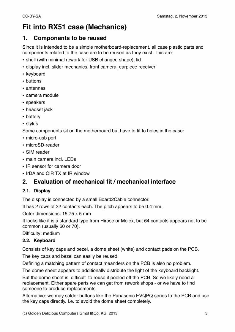
Fit into RX51 case (Mechanics)1. Components to be reusedSince it is intended to be a simple motherboard-replacement, all case plastic parts and components related to the case are to be reused as they exist. This are:• shell (with minimal rework for USB changed shape), lid• display incl. slider mechanics, front camera, earpiece receiver• keyboard• buttons• antennas• camera module• speakers• headset jack• battery• stylusSome components sit on the motherboard but have to fit to holes in the case:• micro-usb port• microSD-reader• SIM reader• main camera incl. LEDs• IR sensor for camera door• IrDA and CIR TX at IR window
2. Evaluation of mechanical fit / mechanical interface2.1. Display
The display is connected by a small Board2Cable connector.It has 2 rows of 32 contacts each. The pitch appears to be 0.4 mm.Outer dimensions: 15.75 x 5 mmIt looks like it is a standard type from Hirose or Molex, but 64 contacts appears not to be common (usually 60 or 70).Difficulty: medium2.2. Keyboard
Consists of key caps and bezel, a dome sheet (white) and contact pads on the PCB. The key caps and bezel can easily be reused.Defining a matching pattern of contact meanders on the PCB is also no problem.The dome sheet appears to additionally distribute the light of the keyboard backlight. But the dome sheet is difficult to reuse if peeled off the PCB. So we likely need a replacement. Either spare parts we can get from rework shops - or we have to find someone to produce replacements.Alternative: we may solder buttons like the Panasonic EVQPQ series to the PCB and use the key caps directly. I.e. to avoid the dome sheet completely.
CC-BY-SA " Samstag, 2. November 2013
(c) Golden Delicious Computers GmbH&Co. KG, 2013" 3
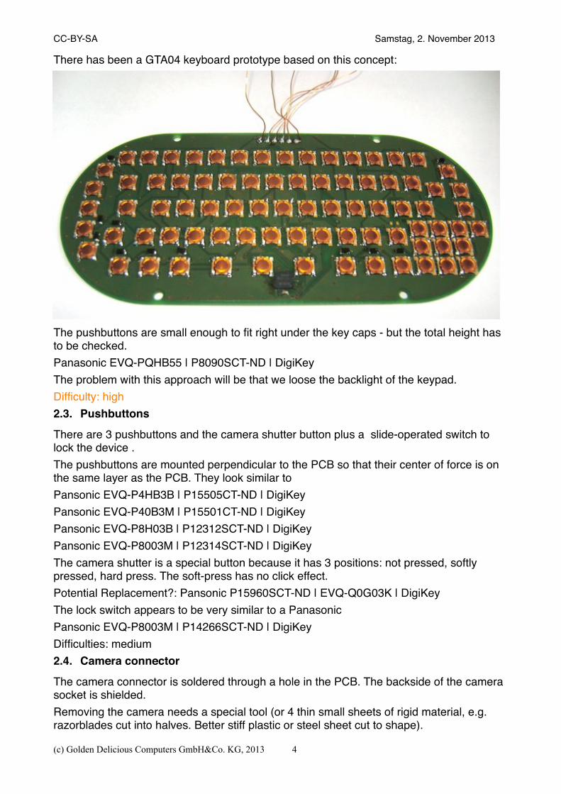
There has been a GTA04 keyboard prototype based on this concept:
The pushbuttons are small enough to fit right under the key caps - but the total height has to be checked.Panasonic EVQ-PQHB55 | P8090SCT-ND | DigiKeyThe problem with this approach will be that we loose the backlight of the keypad.Difficulty: high2.3. Pushbuttons
There are 3 pushbuttons and the camera shutter button plus a slide-operated switch to lock the device .The pushbuttons are mounted perpendicular to the PCB so that their center of force is on the same layer as the PCB. They look similar toPansonic EVQ-P4HB3B | P15505CT-ND | DigiKeyPansonic EVQ-P40B3M | P15501CT-ND | DigiKeyPansonic EVQ-P8H03B | P12312SCT-ND | DigiKeyPansonic EVQ-P8003M | P12314SCT-ND | DigiKeyThe camera shutter is a special button because it has 3 positions: not pressed, softly pressed, hard press. The soft-press has no click effect.Potential Replacement?: Pansonic P15960SCT-ND | EVQ-Q0G03K | DigiKeyThe lock switch appears to be very similar to a PanasonicPansonic EVQ-P8003M | P14266SCT-ND | DigiKeyDifficulties: medium2.4. Camera connector
The camera connector is soldered through a hole in the PCB. The backside of the camera socket is shielded.Removing the camera needs a special tool (or 4 thin small sheets of rigid material, e.g. razorblades cut into halves. Better stiff plastic or steel sheet cut to shape).
CC-BY-SA " Samstag, 2. November 2013
(c) Golden Delicious Computers GmbH&Co. KG, 2013 4
Replacement: unknownFinding a replacement is a good piece of luck and persistence.Alternative: we could try to find a completely different camera module with at least the same quality and very similar dimensions. But an easier to get connector.Important: Fremantle has closed blob picture enhancement libs [(afaik), so we will probably want to keep the original cam module.Difficulty: high2.5. Battery
has three blade contacts with 3.5 mm pitch for BL-5J battery (also used in many other Nokia devices).The third pin from corner is a 100k NTC for temperature and battery presence detection. The GTA04 uses it for a HDQ fuel gauge built into the battery, but it also works without. Or thethe NTC can be connected to the TPS65950.We should try to keep the HDQ function (in parallel to the NTC-ADC if possible) to allow users to build their own smart batteries.There is a battery driver (twl4030-madc) in Linux 3.12 that uses the voltage and charging/discharging state to estimate the battery level.NOTE: the pin assignment is different from the GTA04 - the middle pin is „-“.NOTE: the NTC appears to be 100k instead of 10k as with many other batteries.Difficulty: low-medium2.6. SIM-Reader
We must find a variant that fits through the specially shaped hole in the battery compartment. And it should be as small as possible to get space to find a placement of the UMTS/LTE module.Some candidates:0470230001 Molex Inc | WM3284CT-ND | DigiKey0473882001 Molex Inc | WM3292TR-ND | DigiKey0473880001 Molex Inc | WM3291DKR-ND | DigiKeyDifficulty: medium2.7. MicroSD-Reader
We must find a variant that fits through the hole in the plastics. In the worst case we can ask users to scratch on the pastics to make a little more room.Some candidates:Amphenol 101-00303-68 | 101-00303-68-1-ND | DigiKeyJAE ST1W008S4BR1500 | 670-2345-1-ND | DigiKeyNOTE: RX51 uses a hall sensor to detect battery lid removal and thus unmount and power down the uSD on a quite low level (almost hardware level). If this could get replaced by a switch integrated to the uSD holder, we should prefer that solution.Difficulty: low
CC-BY-SA " Samstag, 2. November 2013
(c) Golden Delicious Computers GmbH&Co. KG, 2013" 5
2.8. 3.5mm AV
Since the 3.5mm connector is a special part clipped into the back cover and has 6 spring contacts we donʻt need a replacement (just the original spare parts). We add contact pads to the PCB.Difficulty: trivial2.9. USB socket
We want to have a Micro-USB-AB (OTG) as a replacement of the Micro-USB-B (client only).Since Micro-USB sockets are standardized, there is only the problem that a Micro-USB-AB socket has a slightly more rectangular shape than the Micro-USB-B, which has more an octagone shape. This requires to scratch the plastics case a little before installation. The same procedure was successful with the GTA04.It would be very important that it does not break off that often as with the RX51, so maybe non-standard soldering procedure (e.g. by hand) required to reinforce Impact: PCB layout. Potential candidate:0475900001 Molex Inc | WM17144CT-ND | DigiKeyNote: we may need a different version where the contacts are at the top.Difficulty: almost trivial2.10.Vibramotor
The Vibramotor is soldered to the PCB.It appears that this is the same model:KHN4NX1RC NMB | P14793CT-ND | DigiKeyDifficulty: trivial2.11.Stereo Speakers
The speakers look like the model Knowles „Petra“ that we have planned to use in the GTA04 case kit. But they appear to be 8 Ohms (and not 32 Ohms).Anyways they have spring loaded contacts and just need contact pads on the PCB.Difficulty: trivial2.12.Microphone
The microphone is soldered to the PCB and is a tiny digital MEMS microphone. The opening is on the top side.There are similar devices from e.g. Knowles and other manufacturers so that it should not be difficult to find a replacement that mechanically fits.NOTE: consider stereo mic designDifficulty: lowShield contactsThere are approx. 7 or 8 contacts for metal shields integrated into snapped in plastics parts.They are so small that it is not easy to find replacements that directly fit. It may be possible to either use small PogoPins soldered to the PCB or use springs from battery connectors.Note: someone has suggested that Würth has such spring contacts (tbc.).Difficulty: medium
CC-BY-SA " Samstag, 2. November 2013
(c) Golden Delicious Computers GmbH&Co. KG, 2013 6
2.13.Antennas
Antennas are also connected by spring contacts soldered to the PCB.So solutions are the same as for Shield contacts.Difficulty: medium
3. PCB3.1. Layers and thickness
the PCB is 0.8mm and that is ok for 8-10 layers using standard technology. Connecting the OMAP 0.4mm BGAs requires 100um or 75 um precision and stacked/plugged microvias-in-pad technology. This can be done by bigger PCB manufacturers (e.g. Würth in Germany or Asian companies).Difficulty: low3.2. Shape
PCB shape must be rebuild almost exactly since some snap-fits of the keybord- bezel and some others from the back cover must exactly fit and pass each other.Difficulty: low3.3. Camera & SD breakout board
The most complex problem is the Camera and SD reader breakout board connected by a flex-PCB created during building the PCB. This is a production process that makes the PCBs very expensive in small quantities.Therefore we need a replacement for connecting the Camera and the Micro-SD reader to the main PCB.There are FFC jumpers in 0.3mm pitch (e.g. Molex) and matching connectors (e.h. Hirose FH23 series), but we may not have enough space for them on the PCBs.Alternative: solder a FPC “cable” to both the main and breakout board PCBDifficulty: medium-high3.4. Volume constraints and Restricted Areas
There are many restricted areas where we can not place components.Height over the PCB surface is also limited at many places to 1.5 - 2mm making it impossible to use bigger (and cheaper) components.The typical height on the SIM-card side is 1.6mm above PCB. Only at two places the shield adds another 0.3mm. These positions are cut out from the battery bay metal and
CC-BY-SA " Samstag, 2. November 2013
(c) Golden Delicious Computers GmbH&Co. KG, 2013" 7
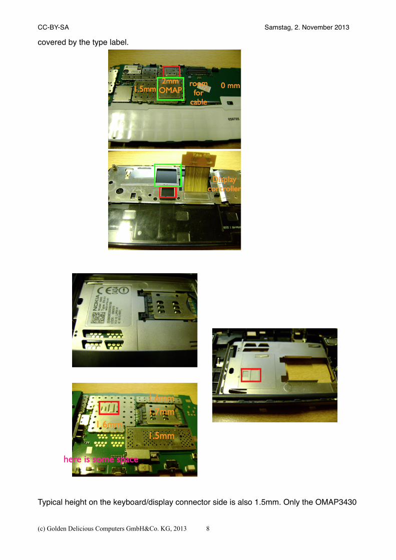
covered by the type label.
Typical height on the keyboard/display connector side is also 1.5mm. Only the OMAP3430
CC-BY-SA " Samstag, 2. November 2013
(c) Golden Delicious Computers GmbH&Co. KG, 2013 8
+ PoP memory has a bump. There is also a matching cutout in the metal of the display mechanics.This means we have to puzzle and squeeze our components inside, but there are not many options for the position. E.g. we must place the DM3730 + PoP memory at exactly the same position or it will not fit with the display mechanics.If we take the height of the GTM601 module (2mm) we already have a problem.For other components like resistors, capacitors and inductors it is possible to find components that are not higher than the space available - and donʻt make short circuits with the battery and display shields. Alternative: a solution could be to cut 4 layers out of the PCB and have the module integrated into the PCB. Problems may be:• heat dissipation• not enough wiring layers under the module• robustness of production (although vapour phase should do it)• non-standard solder paste stencilDifficulty: very high - likely to be unsolvable unless we use the thicker 2-board variant (which does not show obvious difficulties)Alternative: lift the complete display 0.5mm further away from the bottom half, thus increasing the available headroom in picture above from 1.5mm to 2mmExtreme variant of the above: replace the kbd frame by a complete layer between display and base half, showing a 2.8mm high “rim” surface around the whole base half and lifting display as well as kbd by 2.8mm, creating a completely new component plane with a max total height of 2.8mm and option to merge that height with the already existing 1.5mm in the non-kbd area. Given we use a 0.8mm PCB we can place components of max 2.0mm height under the kbd area.This would make a 2-PCB design, where the PCBs are connected by two board-to-board connectors. One PCB would carry Modem + SIM + USB + Battery contacts while the other would carry CPU, Memory, Keyboard, Display.There are no major difficulties to expect for this approach.Recommendation: go for the Extreme variant even if it makes the device thicker and we need to 3D print a spacer.
CC-BY-SA " Samstag, 2. November 2013
(c) Golden Delicious Computers GmbH&Co. KG, 2013" 9
Adapt GTA04 Electronics to RX514. DisplayThe display is seen as a module connected through the 64 pin connector.4.1. Power
The panel needs 1.8V and 2.8V. The front facing camera needs 1.5V, 2.5V and 2.8V. These can be easily provided by the TPS65950 or external LDOs.Difficulty: low4.2. Panel
The GTA04 uses a display with parallel RGB/SYNC/DE/PCLK interface. And a McSPI to reprogram the display module.The RX51 display uses a “panel-acx565akm“ from SONY:http://www.panelook.com/ACX565AKM-7_SONY_3.5_LCM_parameter_17235.htmlIt uses a “CDP“ interface (2 Lane + SPI) with 1.8V levels for I/O.Since the RX51 has a OMAP3430 it should be easily possible to connect it to the DM3730.Difficulty: low4.3. Front camera
The camera needs an I2C interface, an SPI interface and some control signals. All are 1.8V level.Difficulty: low4.4. Backlight
Backlight appears to be 9.6V @ 15 mA. This is not much different from the GTA04 panel and can be adjusted by resistor settings of the TPS61041 backlight converter.Difficulty: trivial4.5. Earpiece
Just needs two wires and some EMI precautions (ferrite, capacitors).Difficulty: trivial4.6. 3 color indicator LED
Difficulty: trivial4.7. Touch
Touch is resistive 4-wire. I.e. we can use the same TSC2007 we have in the GTA04. This will be different from the RX51 which uses SPI as well.NOTE: evaluation to be done, if maemo fremantle wants or needs to keep the original ts-driver.Difficulty: trivial4.8. ALS
Uses I2C Difficulty: trivial
CC-BY-SA " Samstag, 2. November 2013
(c) Golden Delicious Computers GmbH&Co. KG, 2013 10
4.9. Proximity sensor
GPIODifficulty: trivial4.10.Keyboard
MatrixThe GTA04 was already prepared for a keyboard matrix, but since routing all wires from any TWL4030/TPS65090 is almost impossible without adding more layers to the PCB, we have experimented (successfully) with the TCA8418 keyboard scanner connected through I2C. Linux already has a driver for this.A minor issue are shadow keys, but cleverly adding some schottky diodes can solve it.Difficulty: lowBacklightKeyboard backlight are some horizontally shining LEDs.NOTE: on RX51 they are indiviually controlled by 6 outputs of the LED controller, and also have some debug circuitry showing state of certain OMAP signals. Product requirements to be evaluated, probably nobody needs this.Difficulty: low4.11.Audio Codec
The RX51 uses a separate audio codec (tlv320aic34?) maybe because the one in the TWL4030 did not work at market launch.The TPS65950 is available in the third redesign of the original TWL4030 and works well for all functions in the GTA04. So there does not seem to be any need for a separate solution.Due to audio management in fremantle is mostly closed blobs we may need the original TLV320AIC34, since reverse-engineering of the complete audio management seems impossible. Risk to miss mission goal when changing this detail to work different than in RX51: high!TLV320aic34: ~10$, available but duplicates the same functions as are already available in TPS65950 ~5$4.12.Earpiece
The earpiece in the display can be reused.4.13.Stereo speakers
The speakers in the backpart can be reused.4.14.Microphone
The microphone can either be a digital or an analog one, as long as it is small enough for SMD.4.15.FM-Transceiver
In the RX51 there is a separate FM transmitter while the receiver appears to be integrated in the Bluetooh module.From the GTA04 we can use a single Si4721 for both functions.
CC-BY-SA " Samstag, 2. November 2013
(c) Golden Delicious Computers GmbH&Co. KG, 2013" 11

NOTE: seems to also depend on WLAN module (some come with FM functions?). FMTX and FMRX drivers should be adaptable in fremantle kernel and userland. Take care of Audio!Difficulty: medium5. LED controllerThe GTA04 uses a TI TCA6507 that supports 7 open drain outputs for LEDs and can blink/fade them in two banks/patterns.The RX51 uses an LP5523 that supports 9 LEDs and has an integrated charge pump. The LP5523 is now available from Texas Instruments.Both chips are controlled through I2C and Linux drivers are available.Difficulty: trivial6. CamerasConnecting the cameras should be very similar to the RX51.The camera lid detector is IR optical (similar to proxy sensor).Difficulty: low7. USB7.1. Charging
The RX51 uses a special usb charger although the TWL4030 would have all functions.We recommend to use the TPS65950 charging functions because they work without problems in the GTA04.Alternatively, we can look into the new BQ24150 „Fully Integrated Switch-Mode One-Cell Li-Ion Charger with Full USB Compliance and USB-OTG Support“.This would allow to keep the original BME software blob for battery management, though we meanwhile have a working FOSS replacement for that, which is used in non-maemo OS adaptions for RX51.7.2. Fuel gauge
We can integrate a BQ27x00 on the motherboard. This chip (27000 variant) has been working in the GTA02/GTA04 batteries and is connected there through HDQ. BQ27100 has I2C interface. Driver is available and already used in fremantle.Difficulty: low7.3. OTG
The RX51 uses a separate USB-PHY chip while we can just use the one integrated into the TPS65950.The OTG charge pump is also integrated in the TPS65950. Hardware and software are tested to simply work in the GTA04.Difficulty: trivial8. GPSThe GTA04 has a W2SG0084 Sirf IV receiver chip connected to an UART port.The GTA04A5 board is prepared to optionally use the GPS receiver integrated in the GTM610 UMTS modem. This was not connected in earlier boards because a separate GPS receiver allows to deactivate the modem completely in GPS mode.
CC-BY-SA " Samstag, 2. November 2013
(c) Golden Delicious Computers GmbH&Co. KG, 2013 12
We probably shouldn't waste components and real estate for 2 GPS receivers when modem already provides one. GPS disabled state can be guaranteed by switching off antenna (or switch to “external”).Both options use and require an active antenna module with ~20 dB integrated LNA. There is also an antenna switch (for amplified signals) to connect an external GPS antenna with 3V.The RX51 case comes with a passive antenna, so we have to build our own 20 dB LNA.This is critical from PCB layout and shielding to avoid stability issues and possible oscillating.We also have to take care that the MMC clock and data signals are decoupled/shielded/slope-rate-limited well enough so that we avoid 63 x 25 MHz = 1575 MHz.Difficulty: medium9. CPU/Memory/PMICWe want to replace the OMAP3430/PoP/TWL4030 combo with DM3730CBP1000/PoP/TPS65950.They are almost pin compatible and need the same space while giving more modern silicon (i.e. bugs fixed, lower power, higher performance, more memory).Software for this combo is also debugged quite well (BeagleBoard XM, GTA04, OpenPandora).Difficulty: low10. WLAN / BluetoothThe RX51 uses a combined BT/FM module and a separate WLAN module (connected through SPI).The GTA04 uses a combined BT/WLAN module connected through SDIO.This does not impose any significant differences.NOTE: check audio for BTDifficulty: low11. UMTS/LTEWe plan to replace the whole GSM/UMTS system with an OPTION GTM601 module, because it is known (inclusing some issues) from the GTA04.This is connected to the CPU through USB and presents itself as a set of tty ports with AT commands.Additionally we have a PCM interface that is connected to the TPS65950 codec (hardware routing allowing the CPU to suspend during a call) and the CPU (software routing).Remark: RX51 using an APE-centric audio approach and doing massive audio improvement on APE (CPU). BB5 modem is also connected via some sort of “PCM” via ISI, so we should be able to adapt the closed blobs in fremantle by RE.The most problematic aspects are positioning the module in an optimal way, since the wires to the battery, to the SIM reader, to the antenna must be kept as short as possible.Additionally, the module must fit between components fixed in position (battery contacts, SIM reader).Alternatives: find different, smaller LGA UMTS module. Unfortunately the OPTION GTM601 is already one of the smallest if not the one with very low height (2.0mm).
CC-BY-SA " Samstag, 2. November 2013
(c) Golden Delicious Computers GmbH&Co. KG, 2013" 13
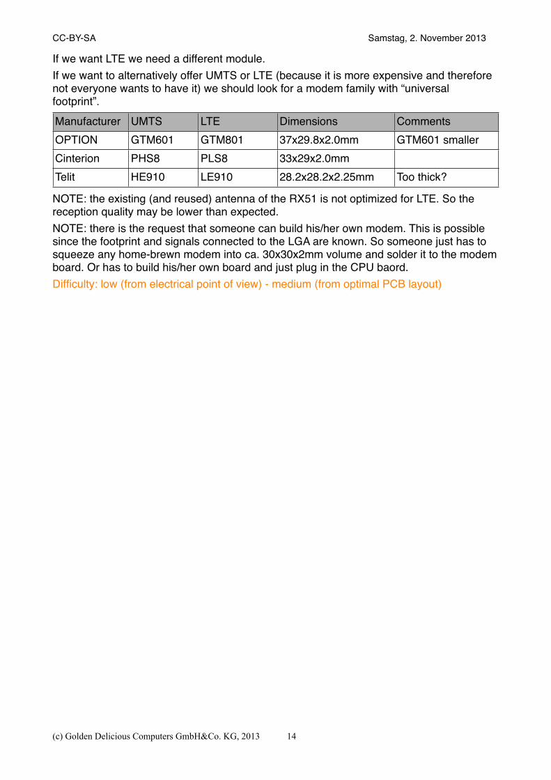
If we want LTE we need a different module.If we want to alternatively offer UMTS or LTE (because it is more expensive and therefore not everyone wants to have it) we should look for a modem family with “universal footprint”.Manufacturer UMTS LTE Dimensions CommentsOPTION GTM601 GTM801 37x29.8x2.0mm GTM601 smallerCinterion PHS8 PLS8 33x29x2.0mmTelit HE910 LE910 28.2x28.2x2.25mm Too thick?
NOTE: the existing (and reused) antenna of the RX51 is not optimized for LTE. So the reception quality may be lower than expected.NOTE: there is the request that someone can build his/her own modem. This is possible since the footprint and signals connected to the LGA are known. So someone just has to squeeze any home-brewn modem into ca. 30x30x2mm volume and solder it to the modem board. Or has to build his/her own board and just plug in the CPU baord.Difficulty: low (from electrical point of view) - medium (from optimal PCB layout)
CC-BY-SA " Samstag, 2. November 2013
(c) Golden Delicious Computers GmbH&Co. KG, 2013 14
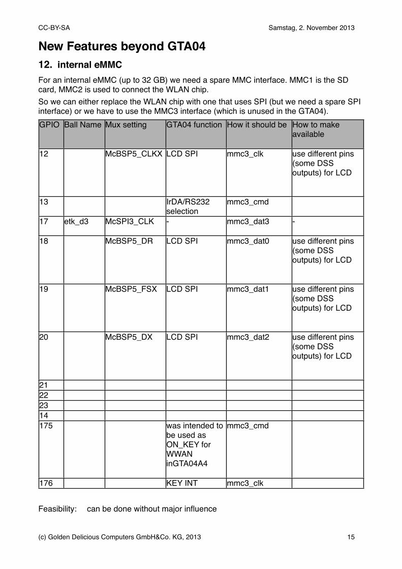
New Features beyond GTA0412. internal eMMCFor an internal eMMC (up to 32 GB) we need a spare MMC interface. MMC1 is the SD card, MMC2 is used to connect the WLAN chip.So we can either replace the WLAN chip with one that uses SPI (but we need a spare SPI interface) or we have to use the MMC3 interface (which is unused in the GTA04).GPIO Ball Name Mux setting GTA04 function How it should be How to make
available
12 McBSP5_CLKX LCD SPI mmc3_clk use different pins (some DSS outputs) for LCD
13 IrDA/RS232 selection
mmc3_cmd
17 etk_d3 McSPI3_CLK - mmc3_dat3 -
18 McBSP5_DR LCD SPI mmc3_dat0 use different pins (some DSS outputs) for LCD
19 McBSP5_FSX LCD SPI mmc3_dat1 use different pins (some DSS outputs) for LCD
20 McBSP5_DX LCD SPI mmc3_dat2 use different pins (some DSS outputs) for LCD
21222314175 was intended to
be used as ON_KEY for WWAN inGTA04A4
mmc3_cmd
176 KEY INT mmc3_clk
Feasibility:" can be done without major influence
CC-BY-SA " Samstag, 2. November 2013
(c) Golden Delicious Computers GmbH&Co. KG, 2013" 15
13. 1GB RAMOMAP4 and many other SoC support 1 GB or more.The OMAP3-PoP needs: 168-Ball NAND Flash and LPDDR PoP (TI OMAP) MCPSuch a memory chip appears to exist:http://www.nanya.com/NanyaAdmin/GetFiles.ashx?ID=1225NT6TL256T32AQ" 8Gb 168-Ball PoP 12mm x 12mm 0.5mm pitchWe have to check1. if the pin layout on page 9 fits to theDM3730.2. check if the supply voltage fits (1.8 V or 1.2 V?)3. support of this RAM chip may need a different configuration in MLO/X-Loader.4. this chip is RAM only. But we need some small NAND that we can boot from (for X-Loader, U-Boot, and U-Boot environment). Or we have to always boot from eMMC (but then it must be connected to MMC1 or MMC2 and not MMC3).Potential distributor to talk to: http://www.memphis.ag/memory-products/linecard/ Feasibility: possible14. Dual/Quad-Core?People want to see a Quad/Octacore Cortex A15.General challenges:• we don't know the CPU (e.g. how do we get really good powermanagement?)• it may be very difficult to get a complete data sheet (OMAP3 is documented on ~3500
pages PDF with open download)• difficult to get sample chips• it may be impossible to get chips at all, since the chip manufaturers have a different
business model. They deliver and sell chips to a hand-selected set of factories that they have trained and enabled to work with their chips. So this means we can't design anything for such chips because we don't get any support. We must order around 100k chips per year to be even considered by them for discussion.
Options to be evaluated:• OMAP4: yey, is possible: Jorjin OMAP4 module exists; same CPU as PandaBoard; but
we donʻt know all hardware details and/or software (power management).Generally, we know a lot more for poer management of an OMAP3/GTA04. But almost nothing (except theory like a TRM) for the OMAP4. I.e. we could make a lot of mistakes hooking up the OMPA4 in a way that prevents optimal power management. And, if we take the Pandabaord as an example, it has no power management and therefore we don't have a power-efficiency optimzed blueprint to learn from. This sums up in that we know the OMAP3 better to optimize power demand than an OMAP4.
• OMAP5: not yet available, needs different PoP memory, appears to require >10 layer PCB; no experience in power management of this SoC.
• iMX6 – chips are easily available and scaleable, but have no PoP; no idea how good power management is.
• Exynos : can't get chips, no public documentations, modules are too big• Snapdragon = chips n/a in small quantities, no public documentation• MediaTek = chips n/a in small quantities, no public documentation
CC-BY-SA " Samstag, 2. November 2013
(c) Golden Delicious Computers GmbH&Co. KG, 2013 16
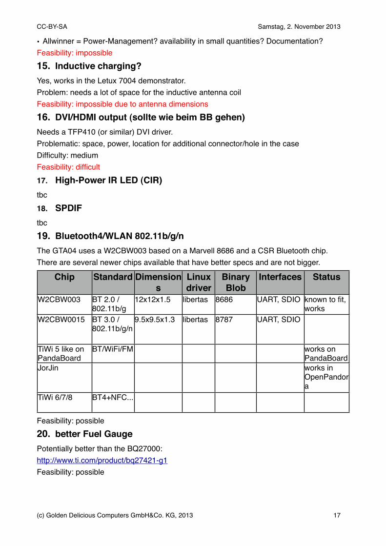
• Allwinner = Power-Management? availability in small quantities? Documentation?Feasibility: impossible15. Inductive charging?Yes, works in the Letux 7004 demonstrator.Problem: needs a lot of space for the inductive antenna coilFeasibility: impossible due to antenna dimensions16. DVI/HDMI output (sollte wie beim BB gehen)Needs a TFP410 (or similar) DVI driver.Problematic: space, power, location for additional connector/hole in the caseDifficulty: mediumFeasibility: difficult17. High-Power IR LED (CIR)tbc18. SPDIFtbc19. Bluetooth4/WLAN 802.11b/g/nThe GTA04 uses a W2CBW003 based on a Marvell 8686 and a CSR Bluetooth chip.There are several newer chips available that have better specs and are not bigger.
Chip Standard Dimensions
Linux driver
Binary Blob
Interfaces Status
W2CBW003 BT 2.0 / 802.11b/g
12x12x1.5 libertas 8686 UART, SDIO known to fit, works
W2CBW0015 BT 3.0 / 802.11b/g/n
9.5x9.5x1.3 libertas 8787 UART, SDIO
TiWi 5 like on PandaBoard
BT/WiFi/FM works on PandaBoard
JorJin works in OpenPandora
TiWi 6/7/8 BT4+NFC...
Feasibility: possible20. better Fuel GaugePotentially better than the BQ27000:http://www.ti.com/product/bq27421-g1Feasibility: possible
CC-BY-SA " Samstag, 2. November 2013
(c) Golden Delicious Computers GmbH&Co. KG, 2013" 17
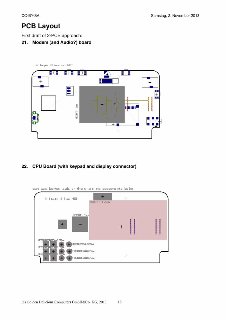
PCB LayoutFirst draft of 2-PCB approach:21. Modem (and Audio?) board
22. CPU Board (with keypad and display connector)
CC-BY-SA " Samstag, 2. November 2013
(c) Golden Delicious Computers GmbH&Co. KG, 2013 18

Next StepsReally designing such a device is a very time consuming task since it must be 100% bug free (or we risk to immediately scrap the first expensive protoypes) and there may be minimal problems (e.g. 0.2 mm space is missing) where it takes several days of discussing and thinking to develop a solution. So this canʻt be done in a hurry and needs taking care of thousands of details (e.g. how to wire some power and audio signals not to risk buzz and other disturbances). EDA tools help to some extent but canʻt help to avoid all such problems. It also means to start over sometimes and build (incomplete) prototypes to verify the design.Doing the final Layout is also very time consuming in such a high-density interconnect (8 layer PCB) and just fiddling the last missing wire into the knot of wires under the CPU may need 3-5 hours intensive work (because other wires have to be moved away but are not allowed to conflict somewhere else).So this makes quite a lot of salary for those engineering expert(s) doing the design and review.Another cost block is really building a handful of prototypes. This includes buying some chips in really small quantities and this may drive the cost by a factor of 2-5 and adds shipment.Then, building 5 or 5000 PCBs does not significantly change the cost of each PCB but the setup of the production process is almost the same. We have to expect several thousands of EUR for running any production batch. And this is also true for the first prototypes - which may show no sign of functions in the first run.If problems are identified by bootstrapping these prototypes (and there will be a handful of problems nobody could imagine before), this step must be repeated. Engineering cost is of course much lower to modify the design than doing it from scratch. Production may be a little cheaper but if the PCB design changes a single wire or a single component is moved by 0.1mm, the production data and tools (e.g. solder stencil mask) can be thrown away because it does not match any more. Since the machinery is not waiting for us to be in operation (it has already been set up and used for different projects), our specific setup has to be redone. I.e. production cost for a second small batch is almost the same as for the first one. It may only need less discussions.The big price reduction of mass production only comes if things are changed less frequently and the machines are continuously producing (copying) exactly the same device. And components are purchased in big reels or full trays instead of being manually cut, put into a protection bag and shipped as a small parcel. This effect is significant and starts at 1000 units per month.Finally we have to pass CE, which adds some more cost, but may require us to run another protoyping loop.
CC-BY-SA " Samstag, 2. November 2013
(c) Golden Delicious Computers GmbH&Co. KG, 2013" 19
Technical Risk AsessmentThe following aspects carry a technical risk that they turn out to be show-stoppers:• Keyboard (dome sheet)• Camera socket• Camera/SD breakout board connection to main PCB• Volume constraints (placing the UMTS modem and other chips into the really tight space
on both PCB sides - the RX51 mechanics is optimized to 0.1mm around the PCB)• spring contacts for shields and antennas• GPS LNA• full audio compatibility to FremantleBut we try our best to find alternatives.
CC-BY-SA " Samstag, 2. November 2013
(c) Golden Delicious Computers GmbH&Co. KG, 2013 20
DisclaimerThis document is based on an evaluation and expresses an opinion, not necessarily facts. It is not a promise or warrant for anything.Everything is subject to change as soon as we get more insights.All trade names and marks are used for referential purposes only.
CC-BY-SA " Samstag, 2. November 2013
(c) Golden Delicious Computers GmbH&Co. KG, 2013" 21