Embed Size (px)
Citation preview

Pages: 12 Questions: 10 ©Copyright for part(s) of this examination may be held by individuals and/or organisations other than the Tasmanian Qualifications Authority.
Tasmanian Certificate of Education
TECHNICAL GRAPHICS
Senior Secondary
Subject Code: TEG315110
External Assessment
2014
Time: Two Hours
On the basis of your performance in this examination, the examiners will provide results on each of the following criteria taken from the course statement: Criterion 2 Complete complex geometric tasks and solve complex problems. Criterion 3 Demonstrate geometric skills in interpreting and transferring
drawings.
TA
SM
AN
IAN
QU
AL
IFIC
AT
ION
S A
UT
HO
RIT
Y
PLACE LABEL HERE

Technical Graphics
Page 2
CANDIDATE INSTRUCTIONS You MUST make sure that your responses to the questions in this examination paper will show your achievement in the criteria being assessed. You must answer SIX questions in total (on the drawing paper provided):
ALL FOUR questions from Section A ONE question from each of Sections B and C
You should spend approximately 60 minutes on Section A and approximately 30 minutes on each of the other two questions. You are required to use correct linework and presentation, and are encouraged to include freehand sketches, where necessary, to show the development of ideas in the solution of problems. Construction must be shown. All dimensions are in millimetres unless otherwise stated. All written responses must be in English.

Technical Graphics
Page 3
SECTION A
Answer ALL questions in this section on the drawing paper provided. Question 1 – This question assesses Criterion 2. The cube in Figure 1 has sides of length 30 mm and has its six faces labelled A to F. Reproduce the cube and plot the isometrically projected path of point P as the cube rolls onto face B, then face E, then face D and finally onto face C.
Figure 1 Question 2 – This question assesses Criterion 3. Construct a regular pentagon with a side length of 50 mm. Increase the area of this pentagon in the ratio 4 : 7.
Section A continues.
A
P
B
C
D
E
F SCALE 1 : 1

Technical Graphics
Page 4
Section A (continued) Question 3 – This question assesses Criteria 2 and 3. Reproduce the irregular pentagon shown in Figure 2. Draw the involute of the pentagon commencing from point P in a clockwise direction.
Figure 2
Section A continues.
SCALE 1 : 1
C
B
D
A
E
P

Technical Graphics
Page 5
Section A (continued) Question 4 – This question assesses Criteria 2 and 3. Figure 3 shows the front view of a public sculpture. The curve AB is parabolic with vertex A and the curve CB is an identical parabola with vertex C. The curve DEF is elliptical and the curve DGF is a portion of the same ellipse. Construct the public sculpture design.
Figure 3
SCALE 1 : 100

Technical Graphics
Page 6
SECTION B
Answer ONE question from this section on the drawing paper provided. This section assesses Criteria 2 and 3 weighted 1 : 4 respectively. Question 5 Figure 4 shows a disc of radius 20 mm that rolls in a clockwise direction (without slipping) from A to B. Plot the path of point P until the centre of the disc is vertically above B.
Figure 4
Section B continues.
SCALE 1 : 1
102
Technical Graphics
Page 7
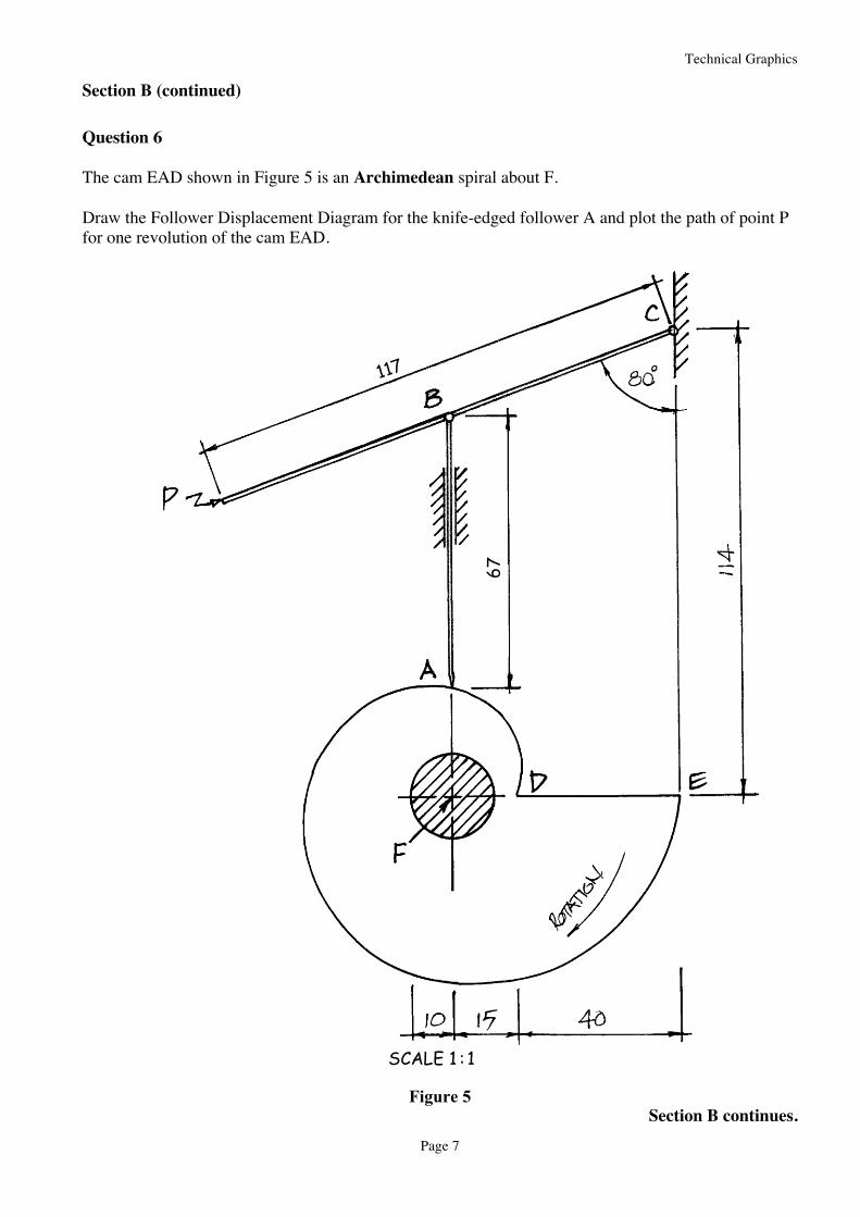
Section B (continued) Question 6 The cam EAD shown in Figure 5 is an Archimedean spiral about F. Draw the Follower Displacement Diagram for the knife-edged follower A and plot the path of point P for one revolution of the cam EAD.
Figure 5 Section B continues.
67
SCALE 1 : 1
117

Technical Graphics
Page 8
Section B (continued) Question 7 The plan and elevation of a small tent are shown in Figure 6. The tent consists of a truncated semi-cone A and a half-cylinder B which is truncated as shown. (a) Redraw the plan and elevation and project an end view from the direction of arrow P. (b) Develop the truncated conical surface of A. (c) Develop the truncated cylindrical surface of B.
Figure 6

Technical Graphics
Page 9
SECTION C
Answer ONE question from this section. This section assesses Criteria 2 and 3 weighted 4 : 1 respectively. Question 8 Figure 7 shows a hexagonal prism intersecting a sphere. On the elevation, draw all the lines of intersection.
Figure 7
Section C continues.
PLAN
ELEVATION
SCALE 1 : 1
16
Technical Graphics
Page 10
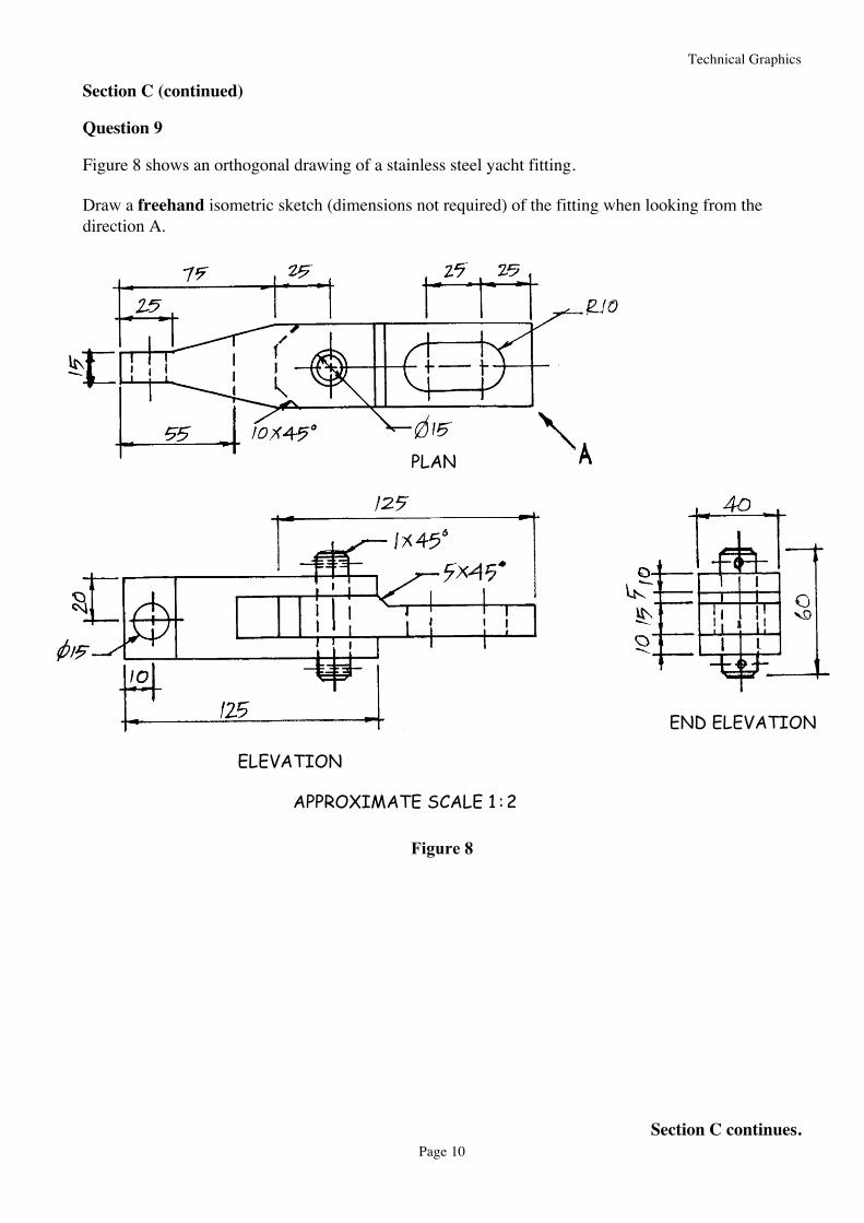
Section C (continued) Question 9 Figure 8 shows an orthogonal drawing of a stainless steel yacht fitting. Draw a freehand isometric sketch (dimensions not required) of the fitting when looking from the direction A.
Figure 8
Section C continues.
APPROXIMATE SCALE 1 : 2
PLAN
ELEVATION
END ELEVATION

Technical Graphics
Page 11
Section C (continued) Question 10 Figure 9 shows a symmetrical pin-jointed roof truss for a warehouse is shown below. (a) Calculate the forces R1 and R2. (b) Calculate the force in Beam X. (c) Is Beam X under compression or tension?
Figure 9
Technical Graphics
Page 12
This question paper and any materials associated with this examination (including answer booklets, cover sheets, rough note paper, or information sheets) remain the property of the Tasmanian Qualifications Authority.