Embed Size (px)
Citation preview
Technical guide bookABB drives

2 ABB drives I Technical guide book

Technical guide book I ABB drives 3
© Copyright 2013 ABB. All rights reserved.
Specifications subject to change without notice.
3AFE64514482 REV G 11.2.2013
ABB drives - Technical guide book

4 ABB drives I Technical guide book
Technical guide book I ABB drives 5
1. Direct torque control explains what DTC is; why and how it has evolved; the basic theory behind its success; and the features and benefits of this new technology.
2. EU Council Directives and adjustable speed electrical power drive systems is to give a straightforward explanation of how the various EU Council Directives relate to power drive systems.
3. EMC compliant installation and configuration for a power drive system assists design and installation personnel when trying to ensure compliance with the requirements of the EMC Directive in the user’s systems and installations when using AC drives.
4. Guide to variable speed drives describes basics of different variable speed drives (VSD) and how they are used in industrial processes.
5. Bearing currents in modern AC drive systems explains how to avoid damages.
6. Guide to harmonics with AC drives describes harmonic distortion, its sources and effect, and also distortion calculation and evaluation with special attention to the methods for reducing harmonics with AC drives.
7. Dimensioning of a drive system. Making dimensioning correctly is the fastest way of saving money. Biggest savings can be achieved by avoiding very basic mistakes. These dimension-ing basics and beyond can be found in this guide.
8. Electrical braking describes the practical solutions available in reducing stored energy and transferring stored energy back into electrical energy.
9. Guide to motion control drives gives an overview of high performance drives and motion control.
10. Functional safety guide introduces the Machinery Directive and the standards that must be taken into account when design-ing a machine, in order to ensure operational safely.
Contents
10
9
8
7
6
5
4
3
2
1

Technical guide No. 1Direct torque control -the world’s most advanced AC drive technology
ABB drives

2 Direct torque control | Technical guide No. 1

Technical guide No. 1 | Direct torque control 3
1
© Copyright 2011 ABB. All rights reserved.
Specifications subject to change without notice.
3AFE58056685 REV C 6.6.2011
Technical guide No. 1Direct torque control - the world’s most advanced AC drive technology

4 Direct torque control | Technical guide No. 1
Technical guide No. 1 | Direct torque control 5
1
Contents
Chapter 1 - Introduction ............................................................................7
General ..............................................................................................7This manual’s purpose ........................................................................7Using this guide .................................................................................7What is a variable speed drive? ...........................................................8Summary ...........................................................................................8
Chapter 2 - Evolution of direct torque control ...........................................8
DC motor drives .................................................................................9Features ........................................................................................9Advantages ...................................................................................9Drawbacks ..................................................................................10
AC drives - Introduction ....................................................................10AC drives - Frequency control using PWM .........................................11
Features ......................................................................................11Advantages .................................................................................12Drawbacks ..................................................................................12
AC drives - Flux vector control using PWM ........................................12Features ......................................................................................12Advantages .................................................................................13Drawbacks ..................................................................................13
AC drives - Direct torque control .......................................................14Controlling variables .....................................................................14
Comparison of variable speed drives .................................................15
Chapter 3 - Questions and answers ........................................................17
General ............................................................................................17Performance ....................................................................................18Operation .........................................................................................24
Chapter 4 - Basic control theory .............................................................28
How DTC works ...............................................................................28Torque control loop...........................................................................29
Step 1 Voltage and current measurements ....................................29Step 2 Adaptive motor model .......................................................29Step 3 Torque comparator and flux comparator .............................30Step 4 Optimum pulse selector ....................................................30
Speed control ..................................................................................31Step 5 Torque reference controller .................................................31Step 6 Speed controller ...............................................................31Step 7 Flux reference controller ....................................................31
Chapter 5 - Index .....................................................................................32

6 Direct torque control | Technical guide No. 1
Technical guide No. 1 | Direct torque control 7
1
Chapter 1 - Introduction
General
Direct torque control - or DTC - is the most advanced AC drive technology developed by any manufacturer in the world.
This technical guide’s purpose
The purpose of this technical guide is to explain what DTC is; why and how it has evolved; the basic theory behind its success; and the features and benefits of this new technology.
While trying to be as practical as possible, this guide does require a basic understanding of AC motor control principles.
It is aimed at decision makers including designers, specifiers, purchasing managers, OEMs and end-users; in all markets such as the water, chemical, pulp and paper, power generation, mate-rial handling, air conditioning and other industries.
In fact, anyone using variable speed drives (VSD) and who would like to benefit from VSD technology will find this technical guide essential reading.
Using this guide
This guide has been designed to give a logical build up as to why and how DTC was developed.
Readers wanting to know the evolution of drives from early DC techniques through AC to DTC should start at chapter 2 (page 8).
For those readers wanting answers about DTC’s performance, operation and application potential, please go straight to chapter 3 (page 17) Questions and answers.
For an understanding of DTC’s basic control theory, turn to page 28.
8 Direct torque control | Technical guide No. 1
Chapter 2 - Evolution of direct torque control
What is a variable speed drive?
To understand the answer to this question we have to understand that the basic function of a variable speed drive (VSD) is to control the flow of energy from the mains to the process.
Energy is supplied to the process through the motor shaft. Two physical quantities describe the state of the shaft: torque and speed. To control the flow of energy we must therefore, ultimately, control these quantities.
In practice, either one of them is controlled and we speak of “torque control” or “speed control”. When the VSD operates in torque control mode, the speed is determined by the load. Likewise, when operated in speed control, the torque is deter-mined by the load.
Initially, DC motors were used as VSDs because they could eas-ily achieve the required speed and torque without the need for sophisticated electronics.
However, the evolution of AC variable speed drive technology has been driven partly by the desire to emulate the excellent performance of the DC motor, such as fast torque response and speed accuracy, while using rugged, inexpensive and mainte-nance free AC motors.
Summary
In this section we look at the evolution of DTC, charting the four milestones of variable speed drives, namely:
– DC motor drives 9 – AC drives, frequency control, PWM 11 – AC drives, flux vector control, PWM 12 – AC drives, direct torque control 14
We examine each in turn, leading to a total picture that identifies the key differences between each.
Technical guide No. 1 | Direct torque control 9
1
Evolution of direct torque control
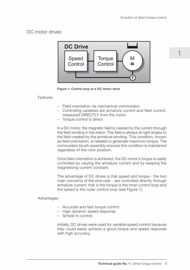
DC motor drives
Figure 1: Control loop of a DC motor drive
Features
– Field orientation via mechanical commutator – Controlling variables are armature current and field current,
measured DIRECTLY from the motor – Torque control is direct
In a DC motor, the magnetic field is created by the current through the field winding in the stator. This field is always at right angles to the field created by the armature winding. This condition, known as field orientation, is needed to generate maximum torque. The commutator-brush assembly ensures this condition is maintained regardless of the rotor position.
Once field orientation is achieved, the DC motor’s torque is easily controlled by varying the armature current and by keeping the magnetising current constant.
The advantage of DC drives is that speed and torque - the two main concerns of the end-user - are controlled directly through armature current: that is the torque is the inner control loop and the speed is the outer control loop (see Figure 1).
Advantages
– Accurate and fast torque control – High dynamic speed response – Simple to control
Initially, DC drives were used for variable speed control because they could easily achieve a good torque and speed response with high accuracy.
10 Direct torque control | Technical guide No. 1
A DC machine is able to produce a torque that is:
– Direct - the motor torque is proportional to the armture current: the torque can thus be controlled directly and accurately.
– Rapid - torque control is fast; the drive system can havea very high dynamic speed response. Torque can bechanged instantaneously if the motor is fed from an idealcurrent source. A vol tage fed dr ive st i l l has a fastresponse, since this is determined only by the rotor’s electrical t ime constant ( ie, the total inductance andresistance in the armature circuit)
– Simple - f ield orientation is achieved using a simplemechanical device called a commutator/brush assembly.Hence, there is no need for complex electronic controlcircuitry, which would increase the cost of the motorcontroller.
Drawbacks
– Reduced motor reliability – Regular maintenance – Motor costly to purchase – Needs encoder for feedback
The main drawback of this technique is the reduced reliability of the DC motor; the fact that brushes and commutators wear down and need regular servicing; that DC motors can be costly to purchase; and that they require encoders for speed and posi-tion feedback.
While a DC drive produces an easily controlled torque from zero to base speed and beyond, the motor’s mechanics are more complex and require regular maintenance.
AC drives - Introduction
– Small size – Robust – Simple in design – Light and compact – Low maintenance – Low cost
The evolution of AC variable speed drive technology has been partly driven by the desire to emulate the performance of the DC drive, such as fast torque response and speed accuracy, while utilising the advantages offered by the standard AC motor.
Evolution of direct torque control
Technical guide No. 1 | Direct torque control 11
1
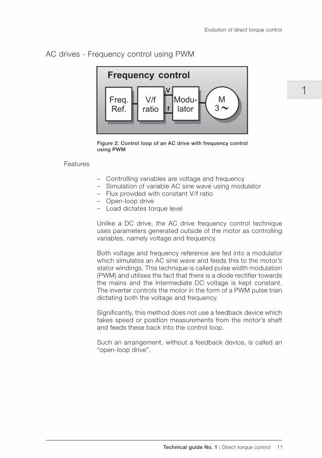
AC drives - Frequency control using PWM
Figure 2: Control loop of an AC drive with frequency control using PWM
Features
– Controlling variables are voltage and frequency – Simulation of variable AC sine wave using modulator – Flux provided with constant V/f ratio – Open-loop drive – Load dictates torque level
Unlike a DC drive, the AC drive frequency control technique uses parameters generated outside of the motor as controlling variables, namely voltage and frequency.
Both voltage and frequency reference are fed into a modulator which simulates an AC sine wave and feeds this to the motor’s stator windings. This technique is called pulse width modulation (PWM) and utilises the fact that there is a diode rectifier towards the mains and the intermediate DC voltage is kept constant. The inverter controls the motor in the form of a PWM pulse train dictating both the voltage and frequency.
Significantly, this method does not use a feedback device which takes speed or position measurements from the motor’s shaft and feeds these back into the control loop.
Such an arrangement, without a feedback device, is called an “open-loop drive”.
Evolution of direct torque control
12 Direct torque control | Technical guide No. 1
Advantages
– Low cost – No feedback device required - simple
Because there is no feedback device, the controlling principle offers a low cost and simple solution to controlling economical AC induction motors.
This type of drive is suitable for applications which do not require high levels of accuracy or precision, such as pumps and fans.
Drawbacks
– Field orientation not used – Motor status ignored – Torque is not controlled – Delaying modulator used
With this technique, sometimes known as scalar control, field orientation of the motor is not used. Instead, frequency and volt-age are the main control variables and are applied to the stator windings. The status of the rotor is ignored, meaning that no speed or position signal is fed back.
Therefore, torque cannot be controlled with any degree of ac-curacy. Furthermore, the technique uses a modulator which basically slows down communication between the incoming voltage and frequency signals and the need for the motor to respond to this changing signal.
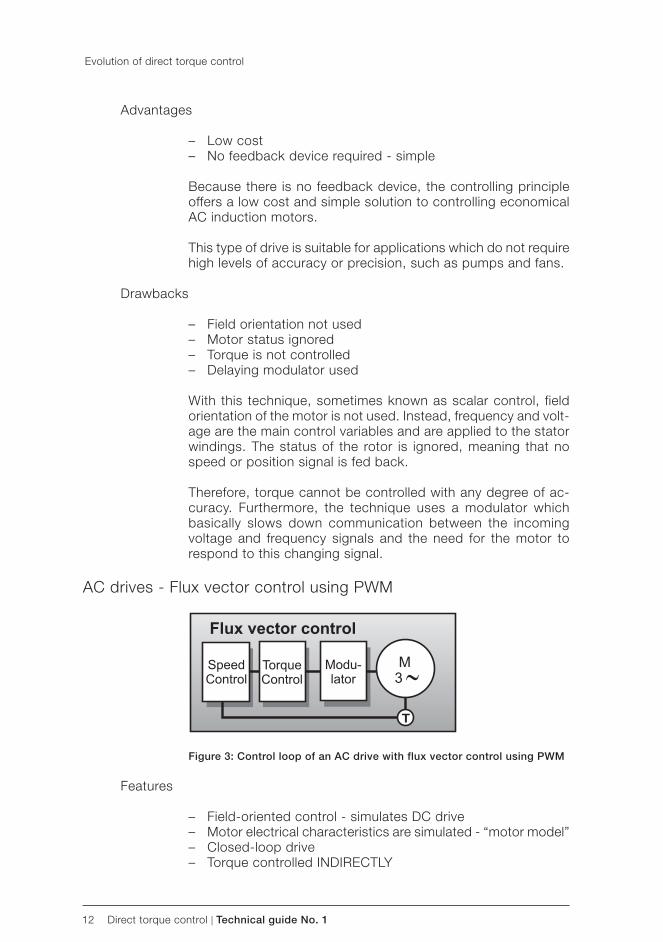
AC drives - Flux vector control using PWM
Figure 3: Control loop of an AC drive with flux vector control using PWM
Features
– Field-oriented control - simulates DC drive – Motor electrical characteristics are simulated - “ motor model” – Closed-loop drive – Torque controlled INDIRECTLY
Evolution of direct torque control
Technical guide No. 1 | Direct torque control 13
1
To emulate the magnetic operating conditions of a DC motor, ie, to perform the field orientation process, the flux-vector drive needs to know the spatial angular position of the rotor flux inside the AC induction motor.
With flux vector PWM drives, field orientation is achieved by elec-tronic means rather than the mechanical commutator/brush assembly of the DC motor.
Firstly, information about the rotor status is obtained by feeding back rotor speed and angular position relative to the stator field by means of a pulse encoder. A drive that uses speed encoders is referred to as a “closed-loop drive”.
Also the motor’s electrical characteristics are mathematically modelled with microprocessors used to process the data.
The electronic controller of a flux-vector drive creates electrical quantities such as voltage, current and frequency, which are the controlling variables, and feeds these through a modulator to the AC induction motor. Torque, therefore, is controlled INDIRECTLY.
Advantages
– Good torque response – Accurate speed control – Full torque at zero speed – Performance approaching DC drive
Flux vector control achieves full torque at zero speed, giving it a performance very close to that of a DC drive.
Drawbacks
– Feedback is needed – Costly – Modulator needed
To achieve a high level of torque response and speed accuracy, a feedback device is required. This can be costly and also adds complexity to the traditional simple AC induction motor.
Also, a modulator is used, which slows down communication between the incoming voltage and frequency signals and the need for the motor to respond to this changing signal.
Although the motor is mechanically simple, the drive is electri-cally complex.
Evolution of direct torque control
14 Direct torque control | Technical guide No. 1
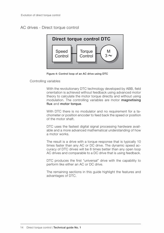
AC drives - Direct torque control
Figure 4: Control loop of an AC drive using DTC
Controlling variables
With the revolutionary DTC technology developed by ABB, field orientation is achieved without feedback using advanced motor theory to calculate the motor torque directly and without using modulation. The controlling variables are motor magnetising flux and motor torque.
With DTC there is no modulator and no requirement for a ta-chometer or position encoder to feed back the speed or position of the motor shaft.
DTC uses the fastest digital signal processing hardware avail-able and a more advanced mathematical understanding of how a motor works.
The result is a drive with a torque response that is typically 10 times faster than any AC or DC drive. The dynamic speed ac-curacy of DTC drives will be 8 times better than any open loop AC drives and comparable to a DC drive that is using feedback.
DTC produces the first “universal” drive with the capability to perform like either an AC or DC drive.
The remaining sections in this guide highlight the features and advantages of DTC.
Evolution of direct torque control
Technical guide No. 1 | Direct torque control 15
1
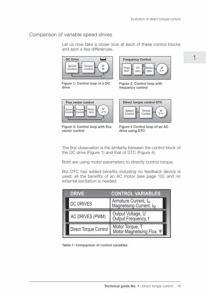
Comparison of variable speed drives
Let us now take a closer look at each of these control blocks and spot a few differences.
Figure 1: Control loop of a DC drive
Figure 2: Control loop with frequency control
Figure 3: Control loop with flux vector control
Figure 4 Control loop of an AC drive using DTC
The first observation is the similarity between the control block of the DC drive (Figure 1) and that of DTC (Figure 4).
Both are using motor parameters to directly control torque.
But DTC has added benefits including no feedback device is used; all the benefits of an AC motor (see page 10); and no external excitation is needed.
Table 1: Comparison of control variables
Evolution of direct torque control
16 Direct torque control | Technical guide No. 1
As can be seen from table 1, both DC drives and DTC drives use actual motor parameters to control torque and speed. Thus, the dynamic performance is fast and easy. Also with DTC, for most applications, no tachometer or encoder is needed to feed back a speed or position signal.
Comparing DTC (Figure 4) with the two other AC drive control blocks (Figures 2 & 3) shows up several differences, the main one being that no modulator is required with DTC.
With PWM AC drives, the controlling variables are frequency and voltage which need to go through several stages before being applied to the motor. Thus, with PWM drives control is handled inside the electronic controller and not inside the motor.
Evolution of direct torque control
Technical guide No. 1 | Direct torque control 17
1
Chapter 3 - Questions and answers
General
What is direct control?
Direct torque control - or DTC as it is called - is the very latest AC drive technology developed by ABB and is set to replace traditional PWM drives of the open- and closed-loop type in the near future.
Why is it called direct torque control?
Direct torque control describes the way in which the control of torque and speed are directly based on the electromagnetic state of the motor, similar to a DC motor, but contrary to the way in which traditional PWM drives use input frequency and voltage. DTC is the first technology to control the “real” motor control variables of torque and flux.
What is the advantage of this?
Because torque and flux are motor parameters that are being directly controlled, there is no need for a modulator, as used in PWM drives, to control the frequency and voltage. This, in effect, cuts out the middle man and dramatically speeds up the response of the drive to changes in required torque. DTC also provides precise torque control without the need for a feedback device.
Why is there a need for another AC drive technology?
DTC is not just another AC drive technology. Industry is de-manding more and existing drive technology cannot meet these demands.
For example, industry wants:
– Better product quality which can be partly achieved with improved speed accuracy and faster torque control.
– Less down time which means a drive that will not trip un-necessarily; a drive that is not complicated by expensive feedback devices; and a drive which is not greatly affected by interferences like harmonics and RFI.
– Fewer products. One drive capable of meeting all appliction needs whether AC, DC or servo. That is a truly “universal” drive.
– A comfortable working environment with a drive that pro-duces much lower audible noise.
18 Direct torque control | Technical guide No. 1
These are just some of the demands from industry. DTC can deliver solutions to all these demands as well as bringing new benefits to many standard applications.
Who invented DTC?
ABB has been carrying out research into DTC since 1988 foll ow-ing the publication of the theory in 1971 and 1985 by German doctor Blaschke and his colleague Depenbrock. DTC leans on the theory of field oriented control of induction machines and the theory of direct self control. ABB has spent over 100 man years developing the technology.
Performance
What are the main benefits of DTC technology over traditional AC drive technology?
There are many benefits of DTC technology. But most signifi-cantly, drives using DTC technology have the following excep-tional dynamic performance features, many of which are obtained without the need for an encoder or tachometer to monitor shaft position or speed:
– Torque response: - How quickly the drive output can reach the specified value when a nominal 100 percent torque refer-ence step is applied. For DTC, a typical torque response is 1 to 2 ms below 40 Hz compared to between 10-20 ms for both flux vector and DC drives fitted with an encoder. With open loop PWM drives (see page 11) the response time is typically well over 100 ms. In fact, with its torque response, DTC has achieved the natural limit. With the voltage and current available, response time cannot be any shorter. Even in the newer “sensorless” drives the torque response is hundreds of milliseconds.
– Accurate torque control at low frequencies, as well as full load torque at zero speed without the need for a feedback device such as an encoder or tachometer. With DTC, speed can be controlled to frequencies below 0.5 Hz and still provide 100 percent torque right the way through to zero speed.
– Torque repeatability: - How well the drive repeats its out-put torque with the same torque reference command. DTC, without an encoder, can provide 1 to 2 percent torque repeat-ability of the nominal torque across the speed range. This is half that of other open-loop AC drives and equal to that of closed-loop AC and DC drives.
Questions and answers
Technical guide No. 1 | Direct torque control 19
1
– Motor static speed accuracy: - Error between speed ref-erence and actual value at constant load. For DTC, speed accuracy is 10 percent of the motor slip, which with an 11 kW motor, equals 0.3 percent static speed accuracy. With a 110 kW motor, speed accuracy is 0.1 percent without en-coder (open-loop). This satisfies the accuracy requirement or 95 percent of industrial drives applications. However, for the same accuracy from DC drives an encoder is needed.
In contrast, with frequency controlled PWM drives, the static speed accuracy is typically between 1 to 3 percent. So the potential for customer process improvements is sig-nificantly higher with standard drives using DTC technology.
A DTC drive using an encoder with 1024 pulses/revolution can achieve a speed accuracy of 0.01 percent.
– Dynamic speed accuracy: - Time integral of speed devia-tion when a nominal (100 percent) torque speed is applied. DTC open-loop dynamic speed accuracy is between 0.3 to 0.4%sec. This depends on the gain adjustment of the controller, which can be tuned to the process requirements.
With other open-loop AC drives, the dynamic accuracy is eight times less and in practical terms around 3%sec.If we furnish the DTC controller with an encoder, the dynamicspeed accu-racy will be 0.1%sec, which matches servo drive performance.
What are the practical benefits of these performance figures?
– Fast torque response: - This significantly reduces the speed drop time during a load transient, bringing much improved process control and a more consistent product quality.
– Torque control at low frequencies: - This is particularly-beneficial to cranes or elevators, where the load needs to be started and stopped regularly without any jerking. Also with a winder, tension control can be achieved from zero through to maximum speed. Compared to PWM flux vector drives, DTC brings the cost saving benefit that no tachometer is needed.
– Torque linearity: - This is important in precision applications like winders, used in the paper industry, where an accurate and consistent level of winding is critical.
– Dynamic speed accuracy: - After a sudden load change, the motor can recover to a stable state remarkably fast.
Questions and answers
20 Direct torque control | Technical guide No. 1
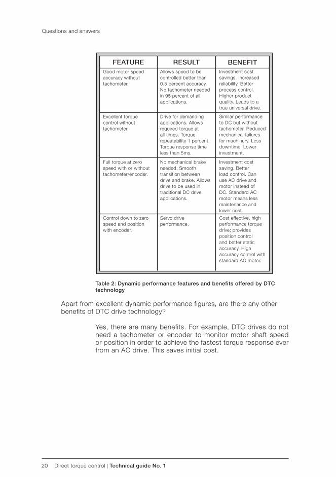
Table 2: Dynamic performance features and benefits offered by DTC technology
Apart from excellent dynamic performance figures, are there any other benefits of DTC drive technology?
Yes, there are many benefits. For example, DTC drives do not need a tachometer or encoder to monitor motor shaft speed or position in order to achieve the fastest torque response ever from an AC drive. This saves initial cost.
Investment cost savings. Increased reliability. Better process control. Higher product quality. Leads to a true universal drive.
Similar performance to DC but without tachometer. Reduced mechanical failures for machinery. Less downtime. Lower investment.
Cost effective, high performance torque drive; provides position control and better static accuracy. High accuracy control with standard AC motor.
Investment cost saving. Better load control. Can use AC drive and motor instead of DC. Standard AC motor means less maintenance and lower cost.
Allows speed to be controlled better than 0.5 percent accuracy. No tachometer needed in 95 percent of all applications.
Drive for demanding applications. Allows required torque at all times. Torque repeatability 1 percent. Torque response time less than 5ms.
No mechanical brake needed. Smooth transition between drive and brake. Allows drive to be used in traditional DC drive applications.
Servo drive performance.
Good motor speedaccuracy without tachometer.
Excellent torque control without tachometer.
Control down to zero speed and position with encoder.
Full torque at zero speed with or without tachometer/ encoder.
FEATURE RESULT BENEFIT
Questions and answers
Technical guide No. 1 | Direct torque control 21
1
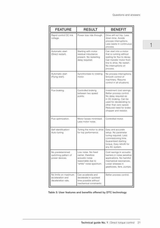
Rapid control DC link voltage.
Power loss ride through. Drive will not trip. Less down time. Avoids process interruptions. Less waste in continuous process.
Automatic start (Direct restart).
Starting with motor residual inductance present. No restarting delay required.
Can start into a motor that is running without waiting for flux to decay. Can transfer motor from line to drive. No restart. No interruptions on process.
Controlled braking between two speed points.
Investment cost savings. Better process control. No delay required as in DC braking. Can be used for decelerating to other than zero speed. Reduced need for brake chopper and resistor.
Flux braking.
Flux optimization. Motor losses minimised. Less motor noise.
Controlled motor.
Self identification/ Auto-tuning.
Tuning the motor to drive for top performance.
Easy and accurate setup. No parameter tuning required. Less commissioning time. Guaranteed starting torque. Easy retrofit for any AC system.
No predetermined switching pattern of power devices.
Low noise. No fixed carrier, therefore acoustic noise reasonable due to “white” noise spectrum.
Cost savings in acoustic barriers in noise sensitive applications. No harmful mechanical resonances. Lower stresses in gearboxes, fans, pumps.
Can accelerate and decelerate in quickest time possible without mechanical constraints.
Automatic start (Flying start).
Synchronises to rotating motor.
No process interruptions. Smooth control of machinery. Resume control in all situations.
No limits on maximum acceleration and deceleration rate.
Better process control.
BENEFITFEATURE RESULT
Table 3: User features and benefits offered by DTC technology
Questions and answers
22 Direct torque control | Technical guide No. 1
Also a DTC drive features rapid starting in all motor electro-magnetic and mechanical states. The motor can be started immediately without delay.
It appears that DTC drives are most advantageous for high performance or demanding drive applications. What benefits does DTC bring to standard drives?
Standard applications account for 70 percent of all variable speed drives installed throughout industry. Two of the most common applications are in fans and pumps in industries like heating, ven-tilating and air conditioning ( HVAC), water and food and drinks.
In these applications, DTC provides solutions to problems like harmonics and noise.
For example, DTC technology can provide control to the drive input line generating unit, where a conventional diode bridge is replaced with a controlled bridge.
This means that harmonics can be significantly reduced with a DTC controlled input bridge. The low level current distortion with a DTC controlled bridge will be less than a conventional 6-pulse or 12-pulse configuration and power factor can be as high as 0.99.
For standard applications, DTC drives easily withstand huge and sudden load torques caused by rapid changes in the process, without any overvoltage or overcurrent trip.
Also, if there is a loss of input power for a short time, the drive must remain energised. The DC link voltage must not drop below the lowest control level of 80 percent. To ensure this, DTC has a 25 microseconds control cycle.
What is the impact of DTC on pump control?
DTC has an impact on all types of pumps. Because DTC leads to a universal drive, all pumps, regardless of whether they are centrifugal or constant torque type (screw pumps) can now be controlled with one drive configuration, as can aerators and conveyors. DTC technology allows a drive to adjust itself to varying application needs.
For example, in screw pumps a drive using DTC technology will be able to adjust itself for sufficient starting torque for a guaranteed start.
Questions and answers
Technical guide No. 1 | Direct torque control 23
1
Improved power loss ride through will improve pumping avail-ability during short power breaks.
The inherent torque control facility for DTC technology allows the torque to be limited in order to avoid mechanical stress on pumps and pipelines.
What is the impact of DTC technology on energy savings?
A feature of DTC which contributes to energy efficiency is a development called motor flux optimization.
With this feature, the efficiency of the total drive (that is controller and motor) is greatly improved in fan and pump applications.
For example, with 25 percent load there is up to 10 percent total energy efficiency improvement. At 50 percent load there can be 2 percent total efficiency improvement.
This directly impacts on operating costs. This feature also sig-nificantly reduces the motor noise compared to that generated by the switching frequency of a traditional PWM drive.
Has DTC technology been used in many installations?
Yes, there are hundreds of thousands of installations in use. For example, one of the world’s largest web machine manufacturers tested DTC technology for a winder in a film finishing process.
The Requirement:Exact torque control in the winder so as to produce high quality film rolls.
The Solution:Open-loop DTC drives have replaced traditional DC drives and latter flux vector controlled AC drives on the centre drives in the rewind station.
The Benefits: Winder station construction simplified and reliability increased. The cost of one tachometer and associated wiring equals that of one 30 kW AC motor. This provides significant investment cost savings.
Questions and answers
24 Direct torque control | Technical guide No. 1
Operation
What is the difference between DTC and traditional PWM methods?
– Frequency control PWM and flux vector PWM
Traditional PWM drives use output voltage and output fre-quency as the primary control variables but these need to be pulse width modulated before being applied to themotor.
This modulator stage adds to the signal processing time and therefore l imits the level of torque and speed response possible from the PWM drive.
Typically, a PWM modulator takes 10 times longer than DTC to respond to actual change.
– DTC control
DTC allows the motor’s torque and stator flux to be used as primary control variables, both of which are obtained directly from the motor itself. Therefore, with DTC, there is no need for a separate voltage and frequency controlled PWM modulator. Another big advantage of a DTC drive is that no feedback device is needed for 95 percent of all drive applications.
Why does DTC not need a tachometer or position encoder to tell it precisely where the motor shaft is at all times?
There are four main reasons for this:
– The accuracy of the motor model (see page 29). – Controlling variables are taken directly from the motor (see
page 29). – The fast processing speeds of the DSP and optimum pulse
selector hardware (see page 30). – No modulator is needed (see page 14).
Questions and answers
Technical guide No. 1 | Direct torque control 25
1
When combined to form a DTC drive, the above features pro-duce a drive capable of calculating the ideal switching voltages 40,000 times every second. It is fast enough to control individual switching pulses. Quite simply, it is the fastest ever achieved.
Once every 25 microseconds, the inverter’s semiconductors are supplied with an optimum switching pattern to produce the required torque. This update rate is substantially less than any time constants in the motor. Thus, the motor is now the limiting component, not the inverter.
What is the difference between DTC and other sensorless drives on the market?
There are vast differences between DTC and many of the sensor-less drives. But the main difference is that DTC provides accurate control even at low speeds and down to zero speed without encoder feedback. At low frequencies the nominal torque step can be increased in less than 1ms. This is the best available.
How does a DTC drive achieve the performance of a servo drive?
Quite simply because the motor is now the limit of performance and not the drive itself. A typical dynamic speed accuracy for a servo drive is 0.1%s. A DTC drive can reach this dynamic accuracy with the optional speed feedback from a tachometer.
How does DTC achieve these major improvements over traditional technology?
The most striking difference is the sheer speed by which DTC operates. As mentioned above, the torque response is the quickest available.
To achieve a fast torque loop, ABB has utilised the latest high speed signal processing technology and spent 100 man years developing the highly advanced motor model which precisely simulates the actual motor parameters within the controller.
For a clearer understanding of DTC control theory, see page 28.
Questions and answers
26 Direct torque control | Technical guide No. 1
Does a DTC drive use fuzzy logic within its control loop?
No. Fuzzy logic is used in some drives to maintain the accelera-tion current within current limits and therefore prevent the drive from tripping unnecessarily. As DTC is controlling the torque directly, current can be kept within these limits in all operating conditions.
A drive using DTC technology is said to be tripless. How has this been achieved?
Many manufacturers have spent years trying to avoid trips during acceleration and deceleration and have found it extraordinarily difficult. DTC achieves tripless operation by controlling the actual motor torque.
The speed and accuracy of a drive which relies on computed rather than measured control parameters can never be realistic. Unless you are looking at the shaft, you are not getting the full picture. Is this true with DTC?
DTC knows the full picture. As explained above, thanks to the so-phistication of the motor model and the ability to carry out 40,000 calculations every second, a DTC drive knows precisely what the motor shaft is doing. There is never any doubt as to the motor’s state. This is reflected in the exceptionally high torque response and speed accuracy figures quoted on pages 18 and 19.
Unlike traditional AC drives, where up to 30 percent of all switch-ings are wasted, a drive using DTC technology knows precisely where the shaft is and so does not waste any of its switchings.
DTC can cover 95 percent of all industrial applications. The exceptions, mainly applications where extremely precise speed control is needed, will be catered for by adding a feedback de-vice to provide closed loop control. This device, however, can be simpler than the sensors needed for conventional closed loop drives.
Even with the fastest semiconductors some dead time is introduced. Therefore, how accurate is the auto-tuning of a DTC drive?
Auto-tuning is used in the initial identification run of a DTC drive (see page 29). The dead time is measured and is taken into ac-count by the motor model when calculating the actual flux. If we compare to a PWM drive, the problem with PWM is in the range 20 to 30 Hz which causes torque ripple.
Questions and answers
Technical guide No. 1 | Direct torque control 27
1
What kind of stability will a DTC drive have at light loads and low speeds?
The stability down to zero speed is good and both torque and speed accuracy can be maintained at very low speeds and light loads. We have defined the accuracies as follows:
Torque accuracy: Within a speed range of 2 to 100 percent and a load range of 10 to100 percent, the torque accuracy is 2 percent.
Speed accuracy: Within a speed range of 2 to 100 percent and a load range of 10 to 100 percent, the speed accuracy is 10 percent of the motor slip. Motor slip of a 37 kW motor is about 2 percent which means a speed accuracy of 0.2 percent.
What are the limitations of DTC?
If several motors are connected in parallel in a DTC-controlled in-verter, the arrangement operates as one large motor. It has no information about the status of any single motor. If the number of motors varies or the motor power remains below 1/8 of the rated power, it would be best to select the scalar control macro.
Can DTC work with any type of induction motor?
Yes, any type of asynchronous, squirrel cage motor.
Questions and answers
28 Direct torque control | Technical guide No. 1
Chapter 4 - Basic control theory
How DTC works
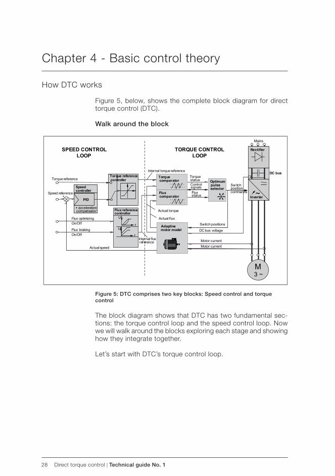
Figure 5, below, shows the complete block diagram for direct torque control ( DTC).
Walk around the block
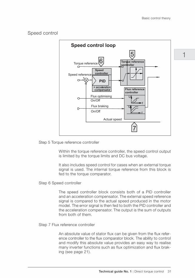
Figure 5: DTC comprises two key blocks: Speed control and torque control
The block diagram shows that DTC has two fundamental sec-tions: the torque control loop and the speed control loop. Now we will walk around the blocks exploring each stage and showing how they integrate together.
Let’s start with DTC’s torque control loop.
Technical guide No. 1 | Direct torque control 29
1
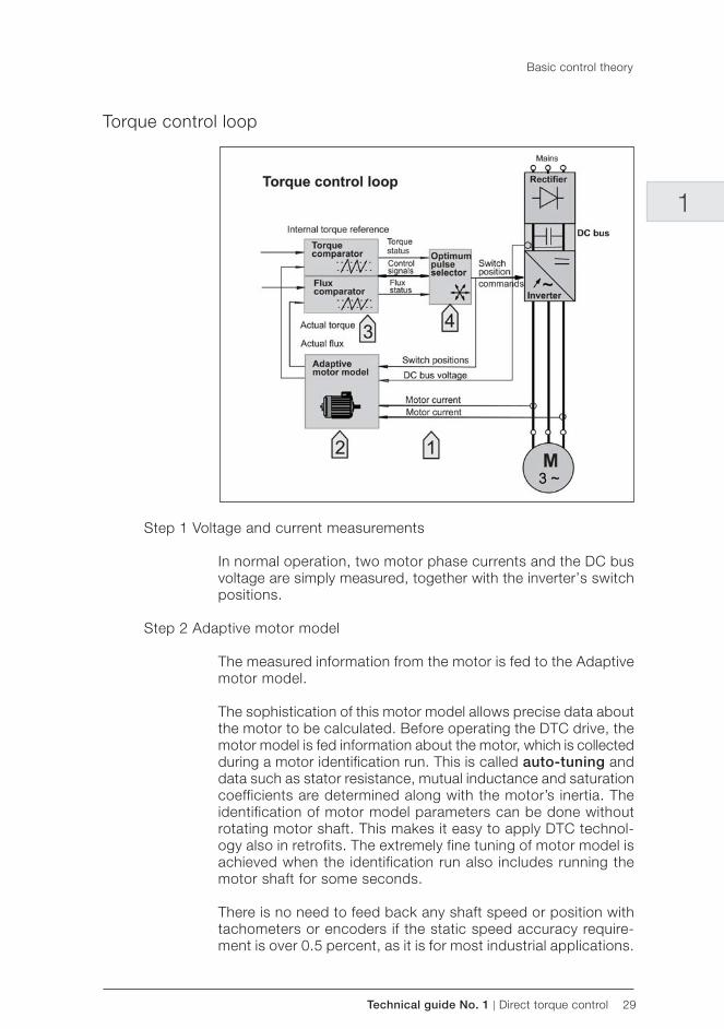
Torque control loop
Step 1 Voltage and current measurements
In normal operation, two motor phase currents and the DC bus voltage are simply measured, together with the inverter’s switch positions.
Step 2 Adaptive motor model
The measured information from the motor is fed to the Adaptive motor model.
The sophistication of this motor model allows precise data about the motor to be calculated. Before operating the DTC drive, the motor model is fed information about the motor, which is collected during a motor identification run. This is called auto-tuning and data such as stator resistance, mutual inductance and saturation coefficients are determined along with the motor’s inertia. The identification of motor model parameters can be done without rotating motor shaft. This makes it easy to apply DTC technol-ogy also in retrofits. The extremely fine tuning of motor model is achieved when the identification run also includes running the motor shaft for some seconds. There is no need to feed back any shaft speed or position with tachometers or encoders if the static speed accuracy require-ment is over 0.5 percent, as it is for most industrial applications.
Basic control theory
30 Direct torque control | Technical guide No. 1
This is a significant advance over all other AC drive technology. The motor model is, in fact, key to DTC’s unrivalled low speed performance.
The motor model outputs control signals which directly represent actual motor torque and actual stator flux. Also shaft speed is calculated within the motor model.
Step 3 Torque comparator and flux comparator
The information to control power switches is produced in the torque and flux comparator.
Both actual torque and actual flux are fed to the comparators where they are compared, every 25 microseconds, to a torque and flux reference value. Torque and flux status signals are cal-culated using a two level hysteresis control method.
These signals are then fed to the optimum pulse selector.
Step 4 Optimum pulse selector
Within the optimum pulse selector is the latest 40 MHz digital signal processor ( DSP) together with ASIC hardware to determine the switching logic of the inverter. Furthermore, all control signals are transmitted via optical links for high speed data transmission.
This configuration brings immense processing speed such that every 25 microseconds the inverter’s semiconductor switching devices are supplied with an optimum pulse for reaching, or maintaining, an accurate motor torque.
The correct switch combination is determined every control cycle. There is no predetermined switching pattern. DTC has been referred to as “just-in-time” switching, because, unlike traditional PWM drives where up to 30 percent of all switch changes are unnecessary, with DTC each and every switching is needed and used.
This high speed of switching is fundamental to the success of DTC. The main motor control parameters are updated 40,000 times a second. This allows extremely rapid response on the shaft and is necessary so that the motor model (see step 2) can update this information.
It is this processing speed that brings the high performance fig-ures including a static speed control accuracy, without encoder, of ±0.5 percent and the torque response of less than 2 ms.
Basic control theory
Technical guide No. 1 | Direct torque control 31
1
Speed control
Step 5 Torque reference controller
Within the torque reference controller, the speed control output is limited by the torque limits and DC bus voltage.
It also includes speed control for cases when an external torque signal is used. The internal torque reference from this block is fed to the torque comparator.
Step 6 Speed controller
The speed controller block consists both of a PID controller and an acceleration compensator. The external speed reference signal is compared to the actual speed produced in the motor model. The error signal is then fed to both the PID controller and the acceleration compensator. The output is the sum of outputs from both of them.
Step 7 Flux reference controller
An absolute value of stator flux can be given from the flux refer-ence controller to the flux comparator block. The ability to control and modify this absolute value provides an easy way to realise many inverter functions such as flux optimization and flux brak-ing (see page 21).
Basic control theory
32 Direct torque control | Technical guide No. 1
Chapter 5 - Index
Aacceleration compensator 31accuracy control 20AC drive 1, 3, 7, 11, 12, 14, 15, 16, 17, 18, 19, 20, 23, 26, 30AC drive using DTC 14, 15AC drive with flux vector control 12AC motor 20aerators 22air condition 22ASIC 30auto-tuning 21, 26, 29
BBlaschke 18braking 21, 31
Cclosed-loop 12, 18closed-loop drives 12commissioning 21control cycle 30controlled input bridge 22controlling variables 16control loop 9, 11, 12, 14, 15, 26, 28, 29, 31control variables 15, 24conveyors 22costs 20, 21, 23
DDC bus voltage 29, 31DC drive 9, 12, 15, 16, 20DC link voltage 21, 22DC motor 9Depenbrock 18diode bridge 22direct torque control 8, 9, 10, 11, 12, 13, 14, 15, 16, 28drive input line generating unit 22DSP 24, 30DTC 14, 15, 16, 18, 19, 20, 21, 22, 23, 24, 25, 26, 27, 28, 29, 30dynamic speed accuracy 19, 25
Eelectronic controller 16elevators 19encoders 16, 20, 24, 25, 29, 30energy savings 23external speed reference 31external torque signal 31
Ffan 21, 22, 23feedback device 18, 24, 26field oriented control 18film finishing 23
flux braking 21, 31flux comparator 30, 31flux optimization 21, 23, 31flux reference controller 31flux vector 12, 15, 18, 23, 24flux vector control 12, 15food 22frequency control 11, 15, 24fuzzy logic 26
Ggearbox 21
Hharmonics 22heating 22HVAC 22hysteresis control 30
Iinertia 29initial cost 20
Lload torque 18, 22loss of input power 22low frequencies 18, 19, 25
Mmaintenance 20mechanical brake 20modulator 16, 24motor flux optimization 23motor model 12, 24, 25, 26, 29, 30, 31motor noise 21, 23motor static speed 19motor torque 30mutual inductance 29
Nnoise 21, 22, 23nominal torque step 25
Ooperating cost 23optical link 30optimum pulse selector 30output frequency 24output voltage 24
Ppaper industry 19PID controller 31pipelines 23position control 20position encoder 24power factor 22power loss ride through 21, 23

Technical guide No. 1 | Direct torque control 33
1predetermined switching pattern 21, 30pump 21, 22, 23PWM 11, 12, 16, 18, 19, 23, 24, 26, 30PWM AC drive 16, 23, 24, 26, 30
Rreliability 20restart 21retrofit 21
Ssaturation coefficient 29scalar control 27sensorless 25servo drive 20, 25signal processing 24, 25signal processing time 24speed 8, 15, 16, 18, 19, 20, 21, 22, 24, 25, 26, 27, 28, 29, 30, 31speed accuracy 19, 20, 25, 26, 27, 29speed control 26, 28, 30, 31speed controller 31speed control loop 28speed control output 31speed response 24stability 27start 21, 22, 28starting 21, 22static accuracy 20static speed accuracy 19, 29stator 24, 29, 30, 31stator flux 24, 30, 31stator resistance 29stress 21, 23switching pattern 21, 25, 30switching pulses 25
Ttacho 16, 20, 24, 29tachometer 16, 18, 19, 20, 23, 24, 25, 29time constant 25torque 9, 10, 11, 12, 13, 14, 15, 16, 18, 19, 20, 21, 22, 23, 24, 25, 26, 27, 28, 30, 31
- control 9, 12, 14, 20, 23, 28- loop 25- repeatability 20- response 20, 25, 26, 30- ripple 26
torque and flux comparator 30torque comparator 30, 31torque control loop 28torque reference controller 31trip 21, 22, 26
Uuniversal 20, 22
Vvariable speed drives 15, 22ventilating 22voltage 16, 18, 21, 22, 24, 25, 29, 31
Wwater 22web machine 23winder 19, 23
Zzero speed 18, 20, 21, 25, 27
Index

34 Direct torque control | Technical guide No. 1

Contact us
3AFE
5805
6685
RE
V C
EN
6.6
..201
1 #1
5700For more information please contact
your local ABB representative or visit:
www.abb.com/driveswww.abb.com/drivespartners
© Copyright 2011 ABB. All rights reserved. Specifications subject to change without notice.

Technical guide No. 2EU Council Directives and adjustable speed electrical power drive systems
ABB drives

2 EU Council Directives | Technical guide No. 2

Technical guide No. 2 | EU Council Directives 3
© Copyright 2013 ABB. All rights reserved.
Specifications subject to change without notice.
3AFE61253980 REV E 8.2.2013
Technical guide No. 2EU Council Directives and adjustable speed electrical power drive systems
2

4 EU Council Directives | Technical guide No. 2
Technical guide No. 2 | EU Council Directives 5
2
Contents
Chapter 1 - Introduction ............................................................................9
This guide’s purpose...........................................................................9How to use this guide .......................................................................10
Responsibilities and actions .........................................................10Tickboxes ....................................................................................10Cross-referencing ........................................................................10
Chapter 2 - General questions and answers............................................11
What are these EU Council Directives? ..............................................11How does EMC affect me? ...............................................................11What is EMC? ..................................................................................11What is an electromagnetic environment? ..........................................12How does electromagnetic interference show up? .............................12What emissions can drives cause? ....................................................12How is this emission seen? ...............................................................13How do I avoid electromagnetic interference? ....................................13Drives manufacturers must comply with EMC standards then? ...........13If a drive is CE marked, I need not worry. True? ..................................13
Chapter 3 - CE marking ...........................................................................15
What is CE marking and how relevant is it for drives? .........................15What is CE marking for? ...............................................................15Is CE marking a quality mark? ......................................................16What is the legal position regarding CE marking? ..........................16What is the importance of CE marking for purchasers of drives? ....16If I buy a CE marked drive, will I meet the technical requirements of the directives? .........................................................................16What happens if, as an end-user, I put together a system -do I have to put CE marking on? ..................................................17What about spare parts that I buy for a drive? Do I negate the CE mark if I replace a component? .......................17If drives are classed as components, on subassemlies they cannot be EMC certified or carry a CE mark. Is this true? ..............17
In summary ......................................................................................18Components or subassemblies intended for incorporation into an apparatus by the end users ..........................................................18Components or subassemblies intended for incorporation into an apparatus by the other manufacturer or assembler ........................18Finished appliance .......................................................................19Finished appliance intended for the end users ...............................19Finished appliance intended for the other manufacturer or assembler 19Systems (Combination of finished appliances) ...............................19
6 EU Council Directives | Technical guide No. 2
All provisions of the EMC Directive, as defined for apparatus, apply to the combination as a whole. ..........................................................20
Apparatus ...................................................................................20Fixed installation ..........................................................................20Equipment ...................................................................................20
Chapter 4 - Purchasing decisionsfor PDSs .............................................21
What you need to know and do.........................................................21If you are a machine builder buying a PDS... ......................................25
Actions you must take ..................................................................26If you are a system designer... ...........................................................28
Path 1 .........................................................................................29Actions you must take ..................................................................29Path 2 .........................................................................................30Actions you must take ..................................................................31
If you are an end-user buying a CDM/BDM or PDS ............................31...You have the following responsibilities ........................................31Actions you must take ..................................................................32
If you are a panel builder buying a CDM/BDM ....................................32Additional actions ........................................................................34
If you are a distributor buying a CDM/BDM... .....................................34If you are an installer buying a CDM/BDM or PDS... ...........................35
Chapter 5 - Terminology ..........................................................................36
Technical documentation (TD) ...........................................................36What is technical documentation? ................................................36Why is technical documentation deemed to be important?.............36Will customers always receive a copy of technical documentation? 37What is the shelf life of technical documentation? ..........................37How do I ensure that tests are always carried out? ........................37Can drive manufacturers help more? .............................................37
How to make up a TD .......................................................................381. Description of the product ........................................................382. Procedures used to ensure product conformity .........................383. If chosen a statement from notified body ...................................394. Actions by the notified body .....................................................39
Technical file (for mechanical safety aspects) .....................................40What is a technical file? ...............................................................40
How to make up a technical file.........................................................40Drawings and diagrams ................................................................40Health and safety .........................................................................40Machine design ...........................................................................40Other certificates required ............................................................40
Certificate of Adequacy .....................................................................41What if standards cannot be wholly implemented? .............................41
How to obtain a Certificate of Adequacy ............................................41Statement ........................................................................................41
When the statement is needed .....................................................41

Technical guide No. 2 | EU Council Directives 7
2
How to obtain a report ......................................................................42Declaration of conformity (for EMC and electrical safety aspects) ...43How to obtain a Declaration of conformity .....................................43What is a Declaration of incorporation? .........................................44Is there no way out of this type of declaration? ..............................45What a Declaration of incorporation contains ................................45
Type certification ..............................................................................46How to obtain type certification .........................................................46
Chapter 6 - Authorities and bodies ..........................................................47
Competent authority .........................................................................47Notified body ...................................................................................47
Chapter 7 - Standards and directives ......................................................48
Directive or standard? .......................................................................48Harmonised standards for PDSs .......................................................48
How to recognise a European standard ........................................49Your questions answered ..................................................................50
Which standards directly relate to drives? .....................................50What are the issues of EN 61800-3 and drives? ............................50What are the solutions to radiated emissions? ...............................51Do I have to conform to the standards? ........................................51Can I be fined for not conforming? ...................................................51
The Product Specific Standard EN 61800-3 .......................................51PDS of category C1: ....................................................................52PDS of category C2: ....................................................................52PDS of category C3: ....................................................................53PDS of category C4: ....................................................................53Examples concerning applications of different approaches .............54
Machinery Directive 98/37/EC ...........................................................55How does the Machinery Directive affect my drive? .......................55Where can I obtain a Machinery Directive copy? ............................56
Low Voltage Directive .......................................................................56How does the LVD affect my drive? ..............................................56Why is the Declaration of conformity important? ............................57
EMC Directive ..................................................................................57How does the EMC Directive affect my drive? ...............................57Who has the responsibility to ensure CE marking? .........................58Summary of responsibilities ..........................................................59Achieving conformity with EC Safety Directives ..............................60
Index .......................................................................................................61

8 EU Council Directives | Technical guide No. 2
Technical guide No. 2 | EU Council Directives 9
2
Chapter 1 - Introduction
This guide’s purpose
The aim of this Technical guide No. 2* is to give a straight-forward explanation of how the various EU Council Directives relate to power drive systems (PDSs). For an explanation of the terminolo- gy of PDSs, see pages 21 and 22.
While Electromagnetic Compatibility (EMC) is the subject of most concern within the industry, it must be realised that the EMC Directive is only part of the overall EU initiative on common safety standards.
It is the intention of this guide to offer users of AC or DC power drive systems - whether machine builders, system designers, distributors, OEMs, end-users or installers - some clear practical guidelines and courses of action.
*Notes
1 The content of this technical guide is ABB Oy’s, Drives in-terpretation of events as of July 2007. However, we reserve the right to develop and evolve these interpretations as more details become available from notified bodies (see chapter 6), competent authorities (see chapter 6), organisations and from our own tests.
2 Other technical guides available in this series include:
Technical guide No. 1 - Direct torque control (3AFE58056685)
Technical guide No. 3 - EMC compliant installation and configuration for a power drive
system (3AFE61348280)
Technical guide No. 4 - Guide to variable speed drives (3AFE61389211)
Technical guide No. 5 - Bearing currents in modern AC drive systems (3AFE64230247)
Technical guide No. 6 - Guide to harmonics with AC drives (3AFE64292714)
Technical guide No. 7 - Dimensioning of a drive system (3AFE64362569)
10 EU Council Directives | Technical guide No. 2
Introduction
Technical guide No. 8 - Electrical braking (3AFE64362534)
Technical guide No. 9 - Guide to motion control drives (3AFE68695201)
Technical guide No. 10 - Functional safety (3AUA0000048753)
How to use this guide
The guide is divided into 7 sections.
Section 4 looks at purchasing decisions for PDSs. Please note the following about the structure of this section:
Responsibilities and actions
Each type of purchaser is offered an explanation of their respon-sibilities. This is for awareness. No action is needed.
Following the responsibilities is a set of actions. If the purchaser follows these actions, step-by-step, then conforming to the relevant directives will be straightforward.
Tickboxes
Alongside the actions are tickboxes. Purchasers can photocopy the relevant pages and use them as a checklist with each item being ticked off as it is achieved.
Cross-referencing
Because of the complexity of conforming to each directive, this guide inevitably carries a lot of cross-references to other sec-tions. In the margin you will come across:
Defined on page XX
You are advised to turn to the page number reference.
You will also notice other references within the text. These can be referred to if the item is unclear but is not essential for achiev-ing compliance.
Key point:Within the text you will see:
Key pointThese are key observations that must be observed.
Technical guide No. 2 | EU Council Directives 11
2
Chapter 2 - General questions and answers
It is very important that users of PDSs fully understand all the various rules and regulations and how they apply to PDSs. That is the purpose of this guide.
What are these EU Council Directives?
It is important to realise that EMC cannot be divorced from other European legislation. So before answering this question, we need to look at the other legislation and how it affects the purchase and installation of drives.
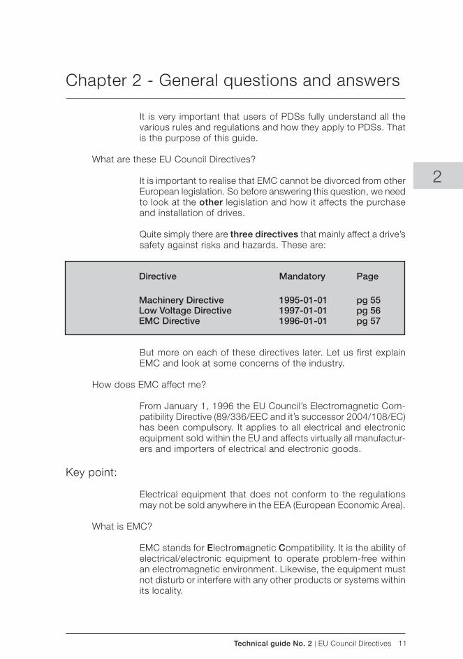
Quite simply there are three directives that mainly affect a drive’s safety against risks and hazards. These are:
But more on each of these directives later. Let us first explain EMC and look at some concerns of the industry.
How does EMC affect me?
From January 1, 1996 the EU Council’s Electromagnetic Com-patibility Directive (89/336/EEC and it’s successor 2004/108/EC) has been compulsory. It applies to all electrical and electronic equipment sold within the EU and affects virtually all manufactur-ers and importers of electrical and electronic goods.
Key point:
Electrical equipment that does not conform to the regulations may not be sold anywhere in the EEA (European Economic Area).
What is EMC?
EMC stands for Electromagnetic Compatibility. It is the ability of electrical/electronic equipment to operate problem-free within an electromagnetic environment. Likewise, the equipment must not disturb or interfere with any other products or systems within its locality.
Directive Mandatory Page
Machinery Directive 1995-01-01 pg 55 Low Voltage Directive 1997-01-01 pg 56 EMC Directive 1996-01-01 pg 57
12 EU Council Directives | Technical guide No. 2
General questions and answers
What is an electromagnetic environment?
The electromagnetic environment is everywhere but it varies from place to place. The reason is that there are many different sources of disturbance which can be natural or man-made.
Natural sources consist of electrical discharge between clouds, lightning or other atmospheric disturbances. While we cannot influence these sources we can protect our products and sys-tems from their effects.
Man-made disturbances are those generated by, for example, electrical contacts and semiconductors, digital systems like mi-croprocessors, mobile radio transmitters, walkie-talkies, portable car telephones and power drive systems.
Such a variety of equipment, each with its own emission char-acteristics, is often used so near to other electrical equipment that the field strengths they create may cause interferences.
Key point:
It is important that all PDSs are immune to these natural and man-made disturbances. While drives manufacturers strive to make their products immune, the directive lays down minimum standards for immunity, thereby ensuring all manufacturers achieve the same basic level.
How does electromagnetic interference show up?
Electromagnetic interference shows up in a variety of ways. Typical examples of interference include a poorly suppressed automobile engine or dynamo; an electric drill causing patterning on the TV screen; or crackling from an AM radio.
The microprocessor and power electronic component, switch rapidly and therefore, can cause interference at high frequencies, unless proper precautions are taken.
What emissions can drives cause?
The normal operation of any drive involves rapid switching of high voltages and this can produce radio frequency emission. It is this radiation and emission that have been seen to have the potential to disturb other circuits at frequencies below 200 MHz.
Modern equipment contains considerable communications and other digital electronics. This can cause considerable emissions at frequencies above 200 MHz.
Technical guide No. 2 | EU Council Directives 13
2
General questions and answers
How is this emission seen?
The main emission is via conduction to the mains. Radiation from the converter and conducting cables is another type of emission and it is especially demanding to achieve the radiated emission limits.
How do I avoid electromagnetic interference?
You need to ensure two things:
– that the equipment generates minimum emission. – that the equipment is immune to outside effects.
Key point:
In the case of power drive systems, a lot depends on the quality of the installation.
Electromagnetic interference needs to be conducted to earth (ground potential) and no system can work unless it is properly grounded.
Drives manufacturers must comply with EMC standards then?
Unfortunately, the process is not that simple. Virtually everyone in the supply chain has a responsibility to ensure a product, a system and an installation complies with the essential require-ments of the EMC Directive.
The key is to clearly understand who has responsibility for what. In the forthcoming pages we take a look at various types of purchasers and examine the steps each should take to meet all three directives mentioned on page 11.
Everyone from manufacturer to installer to user has a responsi-bility in complying with EMC rules.
If a drive is CE marked, I need not worry. True?
Again this is a big misconception. Just because a drive has CE marking does not necessarily mean it meets the EMC Directive.

14 EU Council Directives | Technical guide No. 2
Key point:
This will all become clear by referring to the section purchasing decisions for PDSs, page 21.
CE marking according to the EMC Directive cannot normally be applied to a module that is no more than a chassis with exposed terminals.
General questions and answers
Technical guide No. 2 | EU Council Directives 15
2
Chapter 3 - CE marking
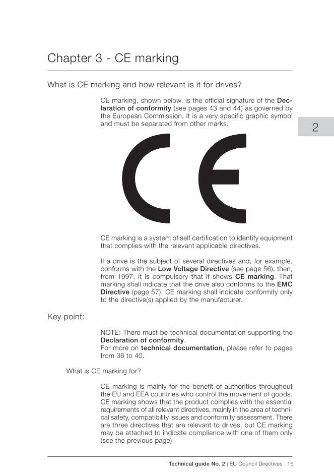
What is CE marking and how relevant is it for drives?
CE marking, shown below, is the official signature of the Dec-laration of conformity (see pages 43 and 44) as governed by the European Commission. It is a very specific graphic symbol and must be separated from other marks.
CE marking is a system of self certification to identify equipment that complies with the relevant applicable directives.
If a drive is the subject of several directives and, for example, conforms with the Low Voltage Directive (see page 56), then, from 1997, it is compulsory that it shows CE marking. That marking shall indicate that the drive also conforms to the EMC Directive (page 57). CE marking shall indicate conformity only to the directive(s) applied by the manufacturer.
Key point:
NOTE: There must be technical documentation supporting the Declaration of conformity. For more on technical documentation, please refer to pages from 36 to 40.
What is CE marking for?
CE marking is mainly for the benefit of authorities throughout the EU and EEA countries who control the movement of goods. CE marking shows that the product complies with the essential requirements of all relevant directives, mainly in the area of techni-cal safety, compatibility issues and conformity assessment. There are three directives that are relevant to drives, but CE marking may be attached to indicate compliance with one of them only (see the previous page).
16 EU Council Directives | Technical guide No. 2
CE marking
Is CE marking a quality mark?
Most definitely not. As CE marking is self certification, you can be assured that certification has been carried out.
What is the legal position regarding CE marking?
Anyone applying CE marking is legally liable and must be able to prove the validity of his actions to the authorities. CE marking confirms compliance with the directives listed in the Declaration of conformity (see pages 43 and 44).
What is the importance of CE marking for purchasers of drives?
As far as a purchaser of a drive is concerned, anything that car-ries the CE mark must have a functional value to him.
Thus, a complete drive product, which can be safely cabled and powered up on its own, shall carry the CE marking.
If I buy a CE marked drive, will I meet the technical requirements of the directives?
In practice, you will see drive products with CE marking. But it is important to understand just why the product was given CE marking in the first place.
Basically a drive has no functional value. It is only of practical use when connected to, say, a motor which in turn is connected to a load.
Therefore, as far as the Machinery Directive is concerned a drive cannot have CE marking unless it is part of a “process” compris-ing the drive, motor and load.
As for the EMC Directive, the equipment that make up a “process” include cabling, drives and motor. CE marking can only be affixed if all items forming such a “process” conform to the requirements of the directive. Therefore, the drive manuals include detailed instructions for installation.
However, in the eyes of the Low Voltage Directive, a built drive does have functionality. That is, through the drive’s parameters you can program the drive and obtain an input and output signal. Thus, if a drive conforms to the Low Voltage Directive it can carry CE marking. Refer to pages from 58 to 60 for explanations of the three directives.
Technical guide No. 2 | EU Council Directives 17
2
CE marking
What happens if, as an end-user, I put together a system -do I have to put CE marking on?
Yes. Anyone putting together a system and commissioning it is responsible for the appropriate CE marking.
Key point:
Turn to page 31 for more details about the end-user’s respon-sibilities.
What about spare parts that I buy for a drive? Do I negate the CE mark if I replace a component?
Equipment supplied before the application of the directives, can be repaired and supplied with spare parts to bring it back to the original specification. However, it cannot be enhanced or reinstalled without meeting the directives.
For equipment supplied after the application of the directives, the use of the manufacturer’s spare parts should not negate the CE marking. However, the manufacturer or supplier should be consulted about upgrading, as some actions could affect the CE marking criteria.
If drives are classed as components, on subassemlies they cannot be EMC certified or carry a CE mark. Is this true?
You need to first understand the terminology now being applied to drives. See below and pages 21 and 22 for this.
A complete drive module (CDM) is normally a component in a system and as such has no functional value unless it is connected to the motor when it becomes a PDS.
The CDM shall be CE marked if it is to be installed with simple connections and adjustments that do not require any EMC-knowledge.
If awareness of the EMC implication is needed in order to install a CDM, it is not considered as an apparatus. Thus, it shall not be CE marked according to the EMC directives.
If a CDM or BDM is intended for incorporation in PDS by profes-sional manufacturers only (panel builders, machine builders), it shall not be CE marked, nor is Declaration of conformity given by the CDM/BDM manufacturer. Instead installation instructions shall be supplied in order to help the professional manufacturers.
18 EU Council Directives | Technical guide No. 2
In summary
The EMC Directive defines equipment as any apparatus or fixed installation. As there are separate provisions for apparatus and fixed installations, it is important that the correct category of the equipment is determined.
In technical-commercial classifications the following terminol-ogy is frequently used: components, sub-assemblies, finished appliances (ie, finished products), a combination of finished appliances (ie, a system), apparatus, fixed installations and equipment.
The key issue here is whether the item to be considered is for end users or not: – If it is meant for end users, the EMC directive applies – If it is meant for manufacturers or assemblers, the EMC direc-
tive does not apply
Components or subassemblies intended for incorporation into an apparatus by the end users
A manufacturer may place components or sub-assemblies on the market which are: – For incorporation into an apparatus by the end-user, – Available to end users and likely to be used by them.
These components or sub-assemblies are to be considered as apparatus with regard to the application of the EMC. The instruc-tions for use accompanying the component or sub-assembly should include all relevant information, and should assume that adjustments or connections can be performed by an end-user not aware of the EMC implications.
Some variable speed power drive products fall into this category, eg, a drive with enclosure and sold as a complete unit (CDM) to the enduser who installs it into his own system. All provisions of the EMC Directive will apply (CE mark, Declaration of conformity and technical documentation).
Components or subassemblies intended for incorporation into an apparatus by the other manufacturer or assembler
Components or sub-assemblies intended for incorporation into an apparatus or an other sub-assembly by other manufacturers or assemblers are not considered to be “apparatus” and are therefore not covered by the EMC Directive. These components include resistors, cables, terminal blocks, etc.
CE marking
Technical guide No. 2 | EU Council Directives 19
2
Some variable speed power drive products fall into this category as well, eg, basic drive module (BDM). These are meant to be assembled by a professional assembler (eg, panel builder or system manufacturer) into a cabinet not in the scope of delivery of the manufacturer of the BDM. According to the EMC Directive, the requirement for the BDM supplier is to provide instructions for installation and use.
Note:The manufacturer or assembler of the panel or system is re-sponsible for CE mark, Declaration of conformity and technical documentation.
Finished appliance
A finished appliance is any device or unit containing electrical and/or electronic components or sub-assemblies that delivers a function and has its own enclosure. Similarly than components, the interpretation finished appliance can be divided into two categories: it can be intended for the end users, or for the other manufacturers or assemblers.
Finished appliance intended for the end users
A finished appliance is considered as apparatus in the sense of the EMC Directive, if it is intended for the end-user and thus has to fulfill all the applicable provisions of the Directive.
Finished appliance intended for the other manufacturer or assembler
When the finished appliance is intended exclusively for an in-dustrial assembly operation for incorporation into other appa-ratus, it is not an apparatus in the sense of the EMC Directive and consequently the EMC Directive does not apply for such finished appliances.
Systems (Combination of finished appliances)
A combination of several finished appliances which is combined, and/or designed and/or put together by the same person (ie, the system manufacturer) and is intended to be placed on the market for distribution as a single functional unit for an end-user and intended to be installed and operated together to perform a specific task.
All provisions of the EMC Directive, as defined for apparatus, apply to the combination as a whole.
CE marking

20 EU Council Directives | Technical guide No. 2
CE marking
Apparatus
Apparatus means any finished appliance or combination thereof made commercially available (ie, placed on the market) as a single functional unit, intended for the end-user, and liable to generate electromagnetic disturbance, or the performance of which is liable to be affected by such disturbance.
Fixed installation
A particular combination of several types of apparatus, equip-ment and/or components, which are assembled, installed and intended to be used permanently at a predefined location.
Equipment
Any apparatus or fixed installation
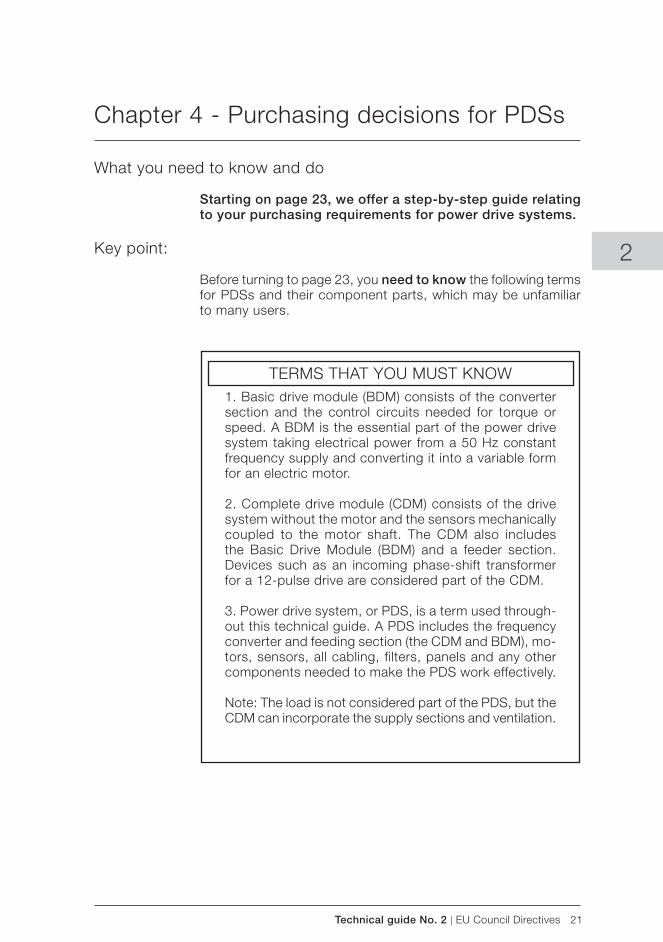
Technical guide No. 2 | EU Council Directives 21
2
Chapter 4 - Purchasing decisions for PDSs
What you need to know and do
Starting on page 23, we offer a step-by-step guide relating to your purchasing requirements for power drive systems.
Key point:
Before turning to page 23, you need to know the following terms for PDSs and their component parts, which may be unfamiliar to many users.
1. Basic drive module (BDM) consists of the converter section and the control circuits needed for torque or speed. A BDM is the essential part of the power drive system taking electrical power from a 50 Hz constant frequency supply and converting it into a variable form for an electric motor.
2. Complete drive module (CDM) consists of the drive system without the motor and the sensors mechanically coupled to the motor shaft. The CDM also includes the Basic Drive Module (BDM) and a feeder section. Devices such as an incoming phase-shift transformer for a 12-pulse drive are considered part of the CDM.
3. Power drive system, or PDS, is a term used through-out this technical guide. A PDS includes the frequency converter and feeding section (the CDM and BDM), mo-tors, sensors, all cabling, filters, panels and any other components needed to make the PDS work effectively.
Note: The load is not considered part of the PDS, but the CDM can incorporate the supply sections and ventilation.
TERMS THAT YOU MUST KNOW
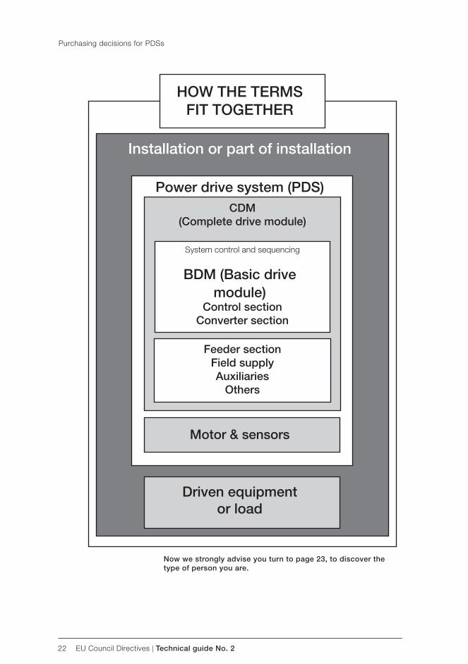
22 EU Council Directives | Technical guide No. 2
Now we strongly advise you turn to page 23, to discover the type of person you are.
Purchasing decisions for PDSs
Power drive system ( PDS) CDM
( Complete drive module)
Feeder sectionField supplyAuxiliaries
Others
Motor & sensors
Driven equipmentor load
Installation or part of installation
HOW THE TERMS FIT TOGETHER
BDM ( Basic drive module)
Control sectionConverter section
System control and sequencing

Technical guide No. 2 | EU Council Directives 23
To make this technical guide easy to use, we have also identified certain types of people who will be involved in the purchasing of drives.
Please identify the type nearest to your job function and turn to the relevant section
Continued overleaf...
2
Purchasing decisions for PDSs
WHO ARE YOU?
25
IF THIS IS YOU, TURN
NOW TO PAGE...
Machine builder is a person who buys either a PDS, CDM or BDM and other mechanical or electrical component parts, such as a pump, and assembles these into a machine.Note: A machine is defined as an assembly of linked parts or components, at least one of which moves. It includes the appropriate actuators, control and power circuits joined together for a specific application, in particular for processing, treatment, moving or packaging of a material.
System designercarries out all the electrical design of the power drive system, specifying all component parts which comprise a PDS.
End-useris the final customer who will actually use the machine, PDS or CDM/BDM.
Panel builderconstructs enclosures into which a panel builder will install a variety of components, including a CDM/BDM and sometimes the motor. However, the built enclosure does not constitute a machine.
28
31
32
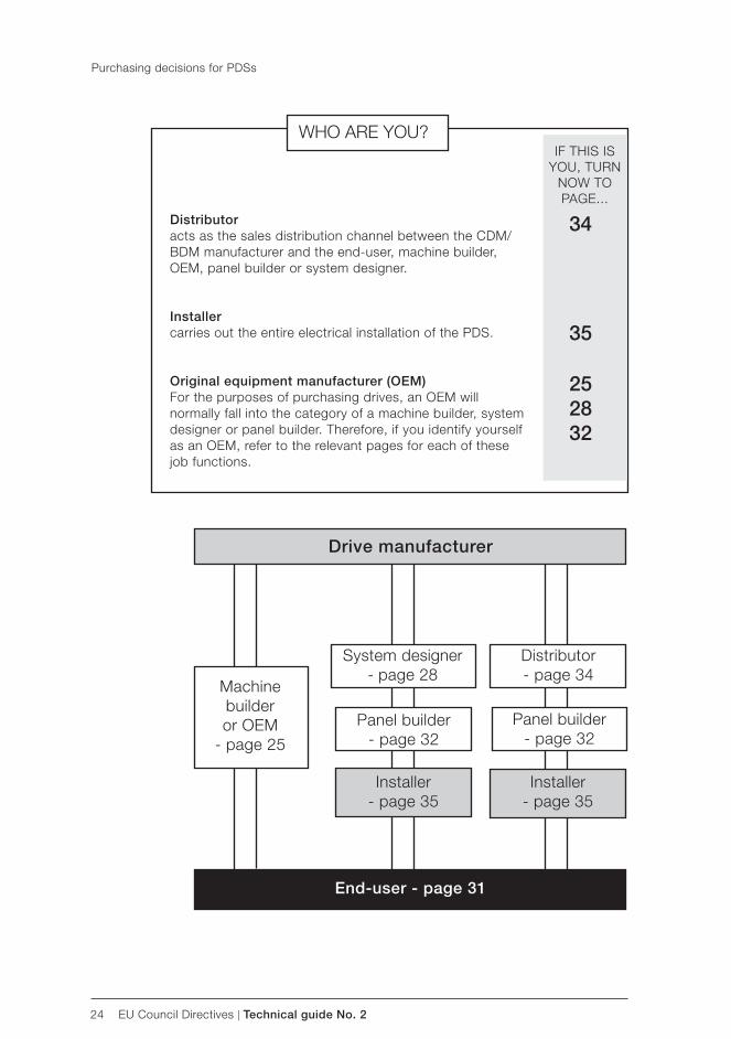
24 EU Council Directives | Technical guide No. 2
Panel builder - page 32
Distributor - page 34
System designer - page 28
Panel builder- page 32
Machine builder or OEM
- page 25
Installer - page 35
Installer - page 35
Purchasing decisions for PDSs
End-user - page 31
Drive manufacturer
WHO ARE YOU?IF THIS IS
YOU, TURN NOW TO PAGE...
252832
Distributor acts as the sales distribution channel between the CDM/BDM manufacturer and the end-user, machine builder, OEM, panel builder or system designer.
Installercarries out the entire electrical installation of the PDS.
Original equipment manufacturer ( OEM) For the purposes of purchasing drives, an OEM will normally fall into the category of a machine builder, system designer or panel builder. Therefore, if you identify yourself as an OEM, refer to the relevant pages for each of these job functions.
35
34
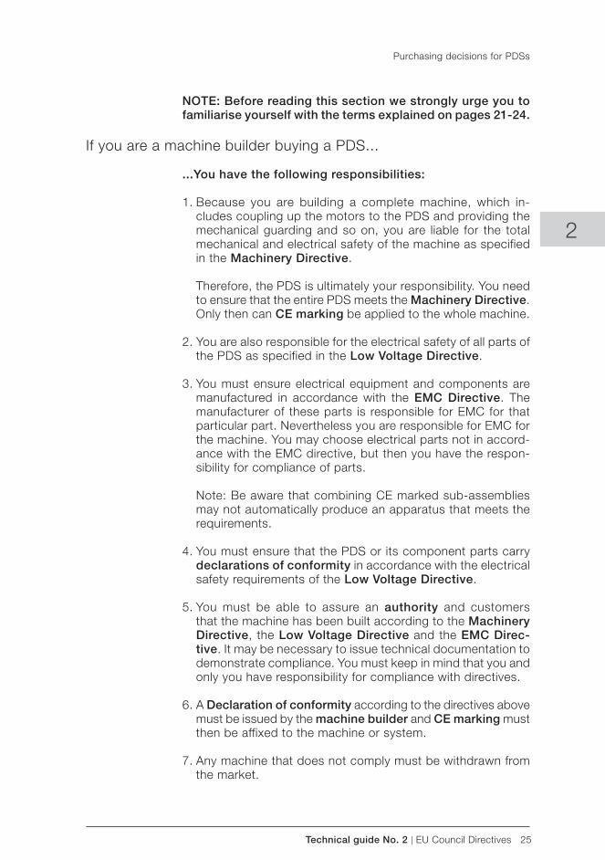
Technical guide No. 2 | EU Council Directives 25
2
NOTE: Before reading this section we strongly urge you to familiarise yourself with the terms explained on pages 21-24.
If you are a machine builder buying a PDS...
...You have the following responsibilities:
1. Because you are building a complete machine, which in-cludes coupling up the motors to the PDS and providing the mechanical guarding and so on, you are liable for the total mechanical and electrical safety of the machine as specified in the Machinery Directive.
Therefore, the PDS is ultimately your responsibility. You need to ensure that the entire PDS meets the Machinery Directive. Only then can CE marking be applied to the whole machine.
2. You are also responsible for the electrical safety of all parts of the PDS as specified in the Low Voltage Directive.
3. You must ensure electrical equipment and components are manufactured in accordance with the EMC Directive. The manufacturer of these parts is responsible for EMC for that particular part. Nevertheless you are responsible for EMC for the machine. You may choose electrical parts not in accord-ance with the EMC directive, but then you have the respon-sibility for compliance of parts.
Note: Be aware that combining CE marked sub-assemblies
may not automatically produce an apparatus that meets the requirements.
4. You must ensure that the PDS or its component parts carry declarations of conformity in accordance with the electrical safety requirements of the Low Voltage Directive.
5. You must be able to assure an authority and customers that the machine has been built according to the Machinery Directive, the Low Voltage Directive and the EMC Direc-tive. It may be necessary to issue technical documentation to demonstrate compliance. You must keep in mind that you and only you have responsibility for compliance with directives.
6. A Declaration of conformity according to the directives above must be issued by the machine builder and CE marking must then be affixed to the machine or system.
7. Any machine that does not comply must be withdrawn from the market.
Purchasing decisions for PDSs
26 EU Council Directives | Technical guide No. 2
Actions you must take
To meet the Machinery Directive (see page 55) you need to:
a. Comply with the following mechanical safety checklist. The aim is to eliminate any risk of accident throughout the
machinery’s life. This is not a complete list, the detailed list is contained within the Machinery Directive:
Eliminate risk as far as possible, taking the necessary protective measures if some risks cannot be eliminated.
Inform users of the residual risks; indicate whether any training is required and stress the need for personal
protective equipment.
Machinery design, construction and instructions must consider any abnormal use.
Under the intended conditions of use, the discomfort, fatigue and stress of the operator must be reduced.
The manufacturer must take account of the operator’s constraints resulting from the use of personal protective equipment.
Machinery must be supplied with all essential equipment to enable it to be used without risk.
b. Comply with the following electrical safety checklist: To ensure the electrical safety of all parts of the PDS as specified in the Low Voltage Directive (refer to page 56) you need to comply with the following safety checklist, which is not necessarily complete.
The electricity supply should be equipped with a discon- necting device and with emergency devices for prevention of unexpected startup.
The equipment shall provide protection of persons against electric shock from direct or indirect contact.
Purchasing decisions for PDSs
Technical guide No. 2 | EU Council Directives 27
2
The equipment is protected against the effects of:
overcurrent arising from a short circuit.
overload current.
abnormal temperatures.
loss of, or reduction in, the supply voltage.
overspeed of machines/machine elements.
The electrical equipment is equipped with an equipotential bond-ing circuit consisting of the:
– PE terminal. – conductive structural parts of the electrical equipment and
the machine. – protective conductors in the equipment or the machine.
The control circuits and control functions ensure safe operation including the necessary inter-lockings, emergency stop, prevention of automatic re-start, etc.
Defined on page 40
c. Compile a technical file for the machine, including the PDS.
Key point:
Generally, must carry CE marking and have a Declaration of conformity.
For machines that pose a high risk of accident, a type certi-fication (see page 46) is required from a notified body. Such machinery is included in Annex IV of the Machinery Directive.
The type certificate issued should be included in the technical file for the machine or safety component. Refer now to page 40.
2. Declarations of conformity from each of the component suppliers whose products make up the PDS
and incorporate them into the technical documenta- tion, referring to all three directives. If buying a PDS from a system designer (see below), he should be able to provide all declarations. If system designer or component supplier cannot provide a Declaration of conformity, the responsibility of demonstrating
compliance according to EMC Directive or Low Voltage Directive lies on machine builder.
Purchasing decisions for PDSs
28 EU Council Directives | Technical guide No. 2
3. Pass this technical documentation to a notif ied body. The machine builder SHOULD NOT pass the file on to an end-user. Based on the technical documentation, obtain a Certificate of Adequacy or technical report from a notified body.
Defined on pages 43, 45 and 46
4. Issue a Declaration of conformity for the entire machine. Only then can you apply CE marking.
5. Pass the Declaration of conformity related to all three directives on to the end-user of the machine.
6. Apply CE marking to the machine.
7. Congratulations! You have successfully complied with the main requirements for safe and efficient operation of a machine.
If you are a system designer
You have the following responsibilities:
1. The PDS is a complex component of the machine. Therefore, the Machinery Directive has to be complied with by issuing a Declaration of incorporation.
2. Because a PDS is not a machine, the only directives which need to be complied with are the Low Voltage Directive and the EMC Directive.
3. The responsibility for Declaration of conformity and apply-ing CE marking rests with both the system designer and the supplier of the component parts which make up the power drive system.
The system designer has to decide if he is going to place his delivery on the market as a single functional unit or not
– if the answer is YES, the delivery shall be classified as a system.
– if the answer is NO, the delivery shall be classified as an installation.
Purchasing decisions for PDSs
Technical guide No. 2 | EU Council Directives 29
2
A. If the delivery is classified as a system, the system designer has to choose one of two paths to follow:
Path 1All components have EMC compliance
1. EMC behaviour is based on a component’s performance.
2. Responsibility lies with the component suppliers for CE marking of individual complex components
3. PDS is an system according to the EMC Directive (as placed on the market as a single functional unit).
4. The Declaration of conformity as well as the instructions for use must refer to the system as whole. The system designer assumes responsibility for compliance with the Directive.
Note 1: The system designer is responsible for producing the instructions for use for the particular system as whole.Note 2: Be aware that combining two or more CE marked sub-assemblies may not automatically produce a system that meets the requirements.
5. No CE marking is required for a system as whole, as long as each part bears the CE mark.
Actions you must take
1. Follow all installation guidelines issued by each of the component suppliers.
2. Issue instructions for use in order to operate the system.
3. Issue technical documentation for the system.
4. Issue a Declaration of conformity.
5. DO NOT issue a CE mark.
Purchasing decisions for PDSs
30 EU Council Directives | Technical guide No. 2
Path 2
Components without EMC compliance
1. EMC behaviour is designed at the system level (no accumulated cost by device specific filters etc).
2. Responsibility lies with the system designer who decides the configuration (place or a specific filter, etc).
3. PDS is a system according to the EMC Directive (as placed on the market as a single functional unit).
4. Declaration of conformity and CE marking are required for the system.
Actions you must take
1. Follow the installation guidelines issued by each of the component suppliers.
2. Optimise the construction of the installation to ensure the design meets the required EMC behaviour, ie, the location of filters.
Defined on pages 36 - 46
3. Issue instructions for use in order to operate the system.
4. Issue technical documentation for the system.
5. Issue a Declaration of conformity and CE mark.
B. If the delivery is an installation, the system designer has one path to follow:
All components have EMC compliance
1. EMC behaviour is based on a component’s performance.
2. Responsibility lies with the component suppliers for CE marking of individual complex components.
3. PDS is an installation according to the EMC Directive.
4. No Declaration of conformity or CE marking is required for a fixed installation, (such as an outside broadcast radio station) DOC and CE marking are needed.
Purchasing decisions for PDSs
Technical guide No. 2 | EU Council Directives 31
2
Actions you must take
1. Follow all installation guidelines issued by each of the component suppliers.
2. Transfer all installation guidelines and Declaration of conformity for each of the components, as issued
by suppliers, to the machine builder.
3. DO NOT issue a Declaration of conformity or CE marking as this is not allowed for fi xed installations.
If you are an end-user buying a CDM/ BDM or PDS
Key point:An end-user can make an agreement with the drive’s supplier so that the supplier acts as the machine builder. However, the end-user is still responsible for the machine’s safety.
The supplier who acts as the machine builder will issue a Dec-laration of conformity when the work is complete.
Once an intermediary panel builder incorporates a CDM/BDM into a panel, he creates a part of a PDS.
The panel builder then has the same responsibilities as the drive’s manufacturer.
...You have the following responsibilities
1. For the total mechanical and electrical safety of the machine of which the drive is part of, as specified in the Machinery Directive.
2. For the electrical safety of the drive as specified in the Low Voltage Directive.
3. To ensure the drive carries a Declaration of conformity in accordance with the electrical safety requirements of the Low Voltage Directive.
4. To be able to demonstrate to the authorities that the machine to which the drive is being fitted has been built to both the Machinery Directive and Low Voltage Directive.
5. The manufacturer of the drive is responsible for determining the EMC behaviour of the drive.
6. The resulting EMC behaviour is the responsibility of the as-sembler of the final product, by following the manufacturer’s recommendations and guidelines.
Purchasing decisions for PDSs
32 EU Council Directives | Technical guide No. 2
Actions you must take
The following needs to be completed by either the end-user directly or the third party engaged to build the machine.
1. To meet the Machinery Directive (refer to page 55) you need to follow the actions listed for a machine builder on pages 25-28.
2. Follow installation instruction issued by manufacturers in order to fulfill the requirements of the EMC Directive and the Low Voltage Directive.
3. Ensure that equipment (CDM/BDM/PDS) is operated according to manufacturer’s instruction in order to guarentee right way of operation.
If you are a panel builder buying a CDM/ BDM
...You have the following responsibilities:
1. The panel builder has two options:
Option A - To buy non- CE marked components
This could save the panel builder money because he buys components which are not tested for EMC or safety. However, the responsibility is then the panel builder’s and this will incur considerable costs as the entire panel needs to be tested.
If the panel builder buys non-CE marked components, the drive may be made to conform without further testing if the components themselves have been tested. However, tested components do not carry the CE mark but must carry suitable instructions for installation. It is these instructions which must be demonstrably met.
Option A - Actions to meet these responsibilities
1. Follow the installation guidelines issued by each of the component suppliers.
2. Optimise the construction of the installation to ensure the design meets the required EMC behaviour, ie, the location of filters.
3. Issue technical documentation for the system. Defined on pages 36-46.
Purchasing decisions for PDSs
Technical guide No. 2 | EU Council Directives 33
2
4. If you choose to assess yourself you must make reference to EMC Directives:
2004/108/EC
And to harmonised standard:
EN 61800-3
And you must make reference to LVD Directive:
2006/95/EC
And corresponding harmonized standard:
EN 61800-5-1 or EN 50178
5. Once testing is completed, the results need to be included in the technical documentation ( TD)
for the panel.
6. Technical documentation shall be assessed by youself in order to demonstrate compliance. You may use Notified Body for assessment as well.
7. You must then issue the Declaration of conformity and CE marking for the panel.
Option B - To buy CE marked components
Option B - Actions to meet these responsibilities
1. Buying CE marked components creates a system or an apparatus (refer to page 17-20) depending on the nature of the panel.
2. Although the panel builder does not have to carry out tests, he must ensure he conforms to the installation guidelines given by each of the component
manufacturers. Note: Be aware that combining two or more CE- marked components may not automatically produce
a system, which meets the requirements.
3. Beware! These guidelines could differ greatly from those given for normal installation purposes because
the components will be in close proximity to each other.
4. Issue instructions for use in order to operate the system or apparatus.
Purchasing decisions for PDSs
34 EU Council Directives | Technical guide No. 2
5. Issue technical documentation.
6. Issue a Declaration of conformity.
7. Apply CE marking to your panel in the case of an apparatus. In the case of a system DO NOT apply CE marking.
Additional actions
The panel can be either sold on the open market or use as part of a machine. For each option there is a different requirement:
1. If you know that the panel is to be used as part of a machine then you must request from the CDM / BDM manufacturer a Declaration of incorporation.
2. The Declaration of incorporation must be supplied with the panel to the machine builder, but CE marking based on Machinery Directive MUST NOT be affixed. This is because CE marking always needs a Declaration of conformity.
Key point:
The Declaration of incorporation CAN NOT be used to apply CE marking.
3. The machine builder will need this Declaration of incorporation because he has to construct a technical documentation ( TD) for the machine and in that file all the declarations need to be included.
If you are a distributor buying a CDM/ BDM...
...You have the following responsibilities:
1. If a distributor is selling boxed products, like CDMs and BDMs (drives), direct from the manufacturer, his only responsibility is to pass on the installation guidelines to the end-user, ma-chine builder or system designer. In addition, the Declara-tion of conformity must be passed to the machine builder or system designer.
2. Both the installation guidelines and the Declaration of conformity are available from the manufacturer.
Purchasing decisions for PDSs

Technical guide No. 2 | EU Council Directives 35
2
Actions you must take to meet these responsibilities
1. Pass all installation guidelines and declaration of con-formities to either the end-user, machine builder or system designer.
If you are an installer buying a CDM/ BDM or PDS...
...You have the following responsibilities:
1. You must ensure that the installation guidelines of the machine builder and/or system designer are adhered to.
Actions you must take to meet these responsibilities
1. Follow machinery builder and/or system designer Instal-lation guidelines.
2. See Technical guide No. 3 for recommended installation guidelines.
Purchasing decisions for PDSs
36 EU Council Directives | Technical guide No. 2
Chapter 5 - Terminology
Technical documentation ( TD)
APPLIED TO: electrical equipment
RESPONSIBILITY: e lect r ica l equ ipment manufacturer, system designer, panel builder, OEM, installer
REQUIRED BY: EMC Directive, Low Voltage Directive
What is technical documentation?
Technical documentation ( TD) must be provided for the entire equipment or system and, if required, is used to show a com-petent authority that you have met the essential requirements of the EMC Directive (see page 57) and Low Voltage Directive (see page 56).
The TD consists of three parts:
1. A description of the product.
2. Procedures used to ensure conformity of the product to the requirements.
3. A statement from a notified body, if third party assessment route is chosen.
Note: Using a notified body is voluntary and can be decided by the manufacturer
Key point:
The full content of the technical documentation are given on pages 36-39.
Why is technical documentation deemed to be important?
Anyone placing a product onto the market within the EU must be able to show that the product meets the requirements of the appropriate EU Council Directive and must be able to dem-onstrate this to a competent authority without further testing.
Technical documentation allows the appropriate Declaration of conformity to be drawn up.
Technical guide No. 2 | EU Council Directives 37
2
Will customers always receive a copy of technical documentation?
The content of the technical documentation is meant for the authorities, and thus the electrical equipment manufacturer does not have to give the technical documentation or any part of it to the customer.
However, as the customer needs to know whether the product is in conformance, he will obtain this assurance from the docu-mentation delivered with the product. It is not required to supply a declaration of conformity with the product, but the end-user may ask for this from the manufacturer.
What is the shelf life of technical documentation?
Any technical documentation must be accessible to the ap-propriate authorities for 10 years from the last relevant product being delivered.
How do I ensure that tests are always carried out?
The whole system is based on self certification and good faith. In various parts of Europe the methods of ensuring compliance will vary. Supervision of these regulations is achieved through market control by a competent authority. If the equipment fails to meet the requirements of the EMC and Low Voltage Directives competent authorities can use the safeguard clause of the Direc-tives (withdraw the product from the market, take legal action).
Can drive manufacturers help more?
Manufacturers accept that there is a need to work more closely with OEMs and machine builders where the converter can be mounted on the machine. A standard assembly or design should be achieved so that no new parts of technical documentation need to be created.
However, the idea of mounting several drives in motor control centres ( MCCs) must be much more carefully thought out by system specifiers, as the summing of high frequency emissions to determine the effects at the MCC terminals is a complex issue and the possibilities of cross coupling are multiplied.
Terminology
38 EU Council Directives | Technical guide No. 2
How to make up a TD
1. Description of the product
(Note: You can photocopy these pages and use as a tickbox checklist)
i. identification of product
a. brand name.
b. model number.
c. name and address of manufacturer or agent.
d. a description of the intended function of the apparatus.
e. any limitation on the intended operating environment.
ii. a technical description
a. a block diagram showing the relationship between the different functional areas of the product.
b. relevant technical drawings, including circuit diagrams, assembly diagrams, parts lists, installation diagrams.
c. description of intended interconnections with other products, devices, etc.
d. description of product variants.
2. Procedures used to ensure product conformity
i. details of significant design elements
a. design features adopted specifically to address EMC and electrical safety problems.
b. relevant component specifications.
c. an explanation of the procedures used to control variants in the design together with an explanation of the procedures used to assess whether a particular change in the design will require the apparatus to be re-tested.
d. details and results of any theoretical modelling of performance aspects of the apparatus.
Terminology

Technical guide No. 2 | EU Council Directives 39
2
Terminology
e. a list of standards applied in whole or part.
f. the description of the solution adopted in order to comply with the directive.
ii. test evidence where appropriate
a. a list of the EMC and electrical safety tests performed on the product, and test reports relating to them, including details of test methods, etc.
b. an overview of the logical processes used to decide whether the tests performed on the apparatus were adequate to ensure compliance with the directive.
c. a list of the tests performed on critical sub-assemblies, and test reports or certificates relating to them.
3. If chosen a statement from notified body
This will include:
i. reference to the exact build state of the apparatus assessed
ii. comment on the technical documentation.
iii. statement of work done to verify the contents and authenticity of the design information.
iv. statement, where appropriate, on the procedures used to control variants, and on environmental, installation and maintenance factors that may be relevant.
4. Actions by the notified body
The notified body will study the technical documentation and issue the statement and this should be included in the technical documentation.
Note: When compiling the technical documentation you may need all Declarations from suppliers, ie, Declaration of con-formity and Declaration of incorporation depending on the parts, to ensure they carry CE marking.

40 EU Council Directives | Technical guide No. 2
Technical file (for mechanical safety aspects)
APPLIED TO: machines and safety components
RESPONSIBILITY: machine builder / system designer
REQUIRED BY: Machinery Directive
What is a technical file?
A technical file is the internal design file which should show how and where the standards are met and is all that is needed if self certifying the equipment by the standards compliance route.
If a Declaration of incorporation is included in a set of papers and this claims to meet the appropriate parts of the standards and simply instructs the user to meet the standards with other parts of his machine, it is possible to use this as a part of a technical file.
How to make up a technical file
Drawings and diagrams
1. Overall drawings of the machine.
2. Control circuit diagrams.
Health and safety
1. All drawings, calculations and test results used to check the machine’s conformity with essential health and safety require-ments.
Machine design
1. Lists of the essential health and safety requirements, harmo-nised standards, other standards and technical specifications used when designing the machine.
2. Description of methods used to eliminate hazards presented by the machine.
Other certificates required
1. A technical report or certificate issued by a notified body - if required.
2. A copy of the instructions for the machine.
Terminology
Technical guide No. 2 | EU Council Directives 41
2
3. For series produced machines, the control measures that are used to ensure that subsequent manufacture remains in conformity with the directive.
Certificate of Adequacy
APPLIED TO: machines / safety components
RESPONSIBILITY: notified body / machine builder
REQUIRED BY: Machinery Directive
What if standards cannot be wholly implemented?
In this case the adequacy of the technical file is proved by a Certificate of Adequacy issued by a notified body.
How to obtain a Certificate of Adequacy
The Certificate of Adequacy is a document drawn up by a notified body. Once the body has established that the techni-cal file contains all the necessary information, the Certificate of Adequacy will be issued.
Key point:
The Certificate of Adequacy provided should be included in the technical file.
Statement
APPLIED TO: electrical equipment
RESPONSIBILITY: notified body
REQUIRED BY: EMC Directive
When the statement is needed
The primary way for manufacturer (or his authorised representa-tive in the Community) to demonstrate the compliance is to use internal production control method. If the manufacturer chooses, he may use other method based on an assessment of a noti-fied body.
Terminology
42 EU Council Directives | Technical guide No. 2
How to obtain the statement
The manufacturer shall present the technical documentation to the notified body and request the notified body for an assess-ment thereof. The manufacturer shall specify to the notified body which aspects of the essential requirements must be assessed.
The notified body shall review the technical documentation and assess whether the technical documentation properly demonstrates that the requirements of the Directive. If the com-pliance of the apparatus is confirmed, the notified body shall issue a statement confirming the compliance of the apparatus.
Key point:
The statement provided shall be included in the technical documentation.
Report
APPLIED TO: electrical equipment
RESPONSIBILITY: notified body / competent body
REQUIRED BY: Low Voltage Directive
What if standards cannot be wholly implemented?
In the event of a challenge the manufacturer or importer may submit a report issued by a notified body. This report is based on the technical file.
How to obtain a report
The report is a document drawn up by a notified body. Once the body has established that the technical documentation contains all the necessary information and the equipment fulfils the require-ments of the Low Voltage Directive, the report will be issued.
Key point:
The report provided should be included in the technical docu-mentation.
Terminology
Technical guide No. 2 | EU Council Directives 43
2
Declaration of conformity (for EMC and electrical safety aspects)
APPLIED TO: electrical equipment and electrical equipment of machines
RESPONSIBILITY: equipment manufacturer
REQUIRED BY: Low Voltage Directive and EMC Directive
How to obtain a Declaration of conformity
You need to provide the following:
1. a reference to the Directive(s),
2. an identification of the apparatus to which it refers (including name, type and serial number),
3. the name and address of the manufacturer and, where appli-cable, the name and address of his authorised representative in the Community,
4. a dated reference to the specifications under which conformity is declared,
5. the date of the declaration,
6. the identity and signature of the person empowered to bind the manufacturer or his authorised representative.
Declaration of conformity (for mechanical safety aspects)
APPLIED TO: machines
RESPONSIBILITY: machine builder
REQUIRED BY: Machinery Directive
How to obtain a Declaration of conformity
You need to provide the following:
1. business name and full address of the manufacturer or, his authorised representative;
2. name and address of the person authorised to compile the technical file, who must be established in the Community;
Terminology
44 EU Council Directives | Technical guide No. 2
3. description and identification of the machinery, including ge-neric denomination, function, model, type, serial number and commercial name;
4. a sentence expressly declaring that the machinery fulfils all the relevant provisions of the machinery Directive
5. where appropriate, the name, address and identification number of the notified body which carried out the EC type-examination and the number of the EC type-examination certificate;
6. where appropriate, the name, address and identification number of the notified body which approved the full quality assurance system;
7. a list to the harmonised standards or the other technical standards and specifications used;
9. the place and date of the declaration as well as the identity and signature of the person empowered to draw up the declaration on behalf of the manufacturer or his authorised representative.
Declaration of incorporation
APPLIED TO: machines or equipment intended for incorporation into other machinery
RESPONSIBILITY: drives manufacturer / machine builder / panel builder
REQUIRED BY: Machinery Directive
What is a Declaration of incorporation?
Drives manufacturers must meet the appropriate parts of the Machinery Directive and provide a Declaration of incorporation which states that the drive does not comply on its own and must be incorporated in other equipment.
This declaration will show the standards that have been applied to the parts of the system within the manufacturer’s scope.
This declaration includes a statement restricting the user from putting the equipment into service until the machinery into which it is to be incorporated, or of which it is to be a component, has been found, and declared, to be in conformity with the provi-sions of the Machinery Directive and the national implementing legislation, ie, as a whole including the equipment referred to in this declaration.
Terminology
Technical guide No. 2 | EU Council Directives 45
2
The declaration then lists the standards relating to the Machinery and Low Voltage Directives which the manufacturer has met.
It concludes that the entire equipment must meet the provisions of the directive.
Quite simply, the manufacturer passes on the responsibility to the machine or system builder.
Is there no way out of this type of declaration?
No. You must understand that because the manufacturer may be supplying only one part in a machinery, such as the inverter, the manufacturer is legally obliged to ensure that whoever puts the system together must check that it is safe.
Only then can the machine or system builder use the Declaration of incorporation in his technical file of the machine.
Key point:
Most manufacturers will include a Declaration of incorporation covering the Machinery Directive for all built PDS products.
What a Declaration of incorporation contains
1. business name and full address of the manufacturer or his authorised representative;
2. description and identification of the partly completed machin-ery including generic denomination, function, model, type, serial number and commercial name;
3. a sentence declaring which essential requirements of the Directive are applied and fulfilled;
4. an undertaking to transmit, in response to a reasoned request by the national authorities, relevant information on the partly completed machinery;
5. a statement that the partly completed machinery must not be put into service until the final machinery into which it is to be incorporated has been declared in conformity with the provi-sions of the Directive;
6. the place and date of the declaration as well as the identity and signature of the person empowered to draw up the declaration on behalf of the manufacturer or his authorised representative.
Terminology

46 EU Council Directives | Technical guide No. 2
Type certification
APPLIED TO: machines and safety components
RESPONSIBILITY: machine builder/approved body
REQUIRED BY: Machinery Directive
How to obtain type certification
Type certification is carried out by an notified body who will es-tablish that the unit supplied, along with a technical file, may be used safely and that any standards have been correctly applied.
Once the type certification has established this, a type exami-nation certificate will be issued.
Terminology
Technical guide No. 2 | EU Council Directives 47
2
Chapter 6 - Authorities and bodies
The responsibility for product conformity is given to the manufac-turer. If there is any doubt about conformity, then the Authorities can demand technical documentation to show that a product complies with the directives concerning the product.
When assessing product conformity, a manufacturer can use a third party to examine the conformity.
The following types of authorities and bodies exist:
Competent authority
A competent authority in any EU or EEA country supervises markets to prevent hazardous products being sold and marketed. They can also withdraw such products from markets.
Notified body
A notified body issues type certificates for products, which have their own directives and/or require type testing.
To find a suitable competent authority or notified body you can contact: EU CommissionEnterprise and Industry DGInformation and Documentation CentreBREY 5 / 150B-1049 BrusselsBelgiumPh: +32 2 296 45 51
Or you may find contact through web.site: http://ec.europa.eu/enterprice/electr_equipment/
48 EU Council Directives | Technical guide No. 2
Chapter 7 - Standards and directives
The use of standards is voluntary, but compliance with directives without the use of harmonised standards is extremely difficult.
There are two ways to show that a power drive system or part of it conform:
– Use of harmonised standards (EN).
– By way of a technical documentation when no harmonised standards exist, or if all parts of a harmonised standard can-not be applied.
Key point:
It is recommended to use technical documentation even when standards are harmonised as it makes it easier to show conform-ity afterwards, if required by authorities.
Directive or standard?
The legislation of the European Union is defined by different directives.
The directives concerning power drive systems are known as new approach directives, which means that they do not include exact figures or limits for products. What they do include is es-sential requirements mainly for health and safety which make the application of the relevant harmonised standards mandatory.
The requirements of directives are firmly established in standards. Standards give exact figures and limits for products.
The responsibility for defining standards in Europe rests with three committees: CEN, for areas of common safety, CENELEC, for electrical equipment and ETSI, for telecommunications.
Harmonised standards for PDSs
To remove technical barriers to trade in EU or EEA countries, the standards are harmonised in member states.
In the harmonisation procedure, all member states are involved in developing the Committee’s proposals for their own national standard. A standard becomes harmonised when published in the Official Journal of the EU.
Technical guide No. 2 | EU Council Directives 49
2
The idea is that if a product conforms to the harmonised standard, it is legally manufactured and when placed onto the market in one country, it must be freely marketed in other member countries.
How to recognise a European standard
Harmonised standards come in the following format:
XX EN 60204-1
where
XX = the national prefix (eg BS = UK; SFS = Finland)EN = the abbreviation of Euronorm60204-1 = an example of a standard number
The numbering of European standards follows a well structured and organized sequence: – EN 50225:1996 (the year of availability of the EN is separated
from the number by a colon) – EN 50157-2-1:1996 (the part number is indicated by a hy-
phen)
The first two numerals indicate the origin of the standard: – 40xxx to 44xxx cover domains of common CEN/ CENELEC
activities in the IT field – 45xxx to 49xxx cover domains of common CEN/ CENELEC
activities outside the IT field – 50xxx to 59xxx cover CENELEC activities, where
– EN 50xxx refer to the standards issued by CENELEC only – EN 55xxx refer to the implementation of CISPR documents
– 60000 to 69999 refer to the CENELEC implementation of IEC documents with or without changes
European standards are adopted and confirmed by CENELEC member countries by adding national prefix before the stand-ard id (for example: SFS-EN 60601-1, DIN EN 60601-1, BS EN 60601-1).
There is also some clue as to a standard’s status:
prEN 50082-2 = proposal for standard sent to member statesENV 50 = pre-standard which is in force for 3 years to obtain practical experience from member states
Standards and Directives
50 EU Council Directives | Technical guide No. 2
Your questions answered
Which standards directly relate to drives?
At the moment, there are three Product Specific Standards which relate to the compliance with EU directives. They are cal led as “EN 61800-3 Adjustable speed electr ical power dr ive systems - Part 3: EMC requirements and specific test methods”, which relates to EMC Directive,“EN 61800-5-1 Adjustable speed electrical power drive systems - Part 5-1: Safety requirements - Electrical, thermal and energy”, which relates to Low Voltage Directive and EN 61800-5-2Adjustable speed electrical power drive systems - Part 5-2: Safety requirements - Functional safety”, which relates to Machinery Directive.
In addition there are other standards, which need to be taken account:
– EN 60204-1, Electrical Equipment of Machines, which, in addition to being a Low Voltage Directive standard for all electrical equipment, is also an electrical safety standard under the Machinery Directive.
– EN 50178 according to Low Voltage Directive and – EN 61800-1/2/4, which give rating specifications for Power
Drive Systems (LV DC, LV AC and MV AC PDS respectively). – EN 61000-3-2 and EN 61000-3-12, which give requirements
for harmonic current caused by equipment
What are the issues of EN 61800-3 and drives?
For emissions there are two main aspects to be considered:
Conducted emissions: these are seen on the power supply cables and will also be measured on the control connections, while radiated emissions are air borne.
Conducted emissions at low frequencies are known as harmonics, which have been a familiar problem to many users of a PDS. Where harmonics are concerned EN 61800-3 refers to EN 61000-3-2, which applies for equipment under 16 A per phase. In addition, the harmonics standard EN 61000-3-12 applies up to 75 A per phase.
At the moment following groups can be separated – Below 16 A per phase
– Professional, over 1kW => No limits. – Other > the limits specified.
– Between 16 A and 75 A per phase – Equipment for public low voltage systems => the limits
specified. – Equipment for other systems => the limits specified
Standards and Directives

Technical guide No. 2 | EU Council Directives 51
2
Conformity with conducted emissions can be helped by good product design and is readily achieved, in most situations, using filters, providing this is for a single drive.
Radiated emissions: These are more problematic. While it is possible to make the drive enclosure into a Faraday cage and thereby have all radiation attenuated to earth, in practice it is the outgoing connections where inadequate cabling radiates emissions and cross couples with other cables in the vicinity. Important attenuation methods are shielded cables and 360o
grounding.
What are the solutions to radiated emissions?
The most important solutions are good installation practice, tight enclosure, shielded cables and 360o grounding. (See Technical guide No. 3 for tips and advice).
Do I have to conform to the standards?
The use of standards is voluntary, but compliance with a Direc-tive without the use of Harmonised Standards is difficult in the majority of cases.
Can I be fined for not conforming?
Yes. Failure to comply with any of the Directives will be a criminal offence.
The Product Specific Standard EN 61800-3
This standard defines the required emission and immunity levels of PDSs and the test methods to measure the levels. In Europe, the standard takes precedence over all generic or product family EMC standards previously applicable.
The standard defines two environments where equipment can be used:
First environment – environment that includes domestic premises, it also includes
establishments directly connected without intermediate trans-formers to a low voltage power supply network which supplies buildings used for domestic purposes. Houses, apartments, commercial premises or offices in a residential building are examples of this kind of locations.
Standards and Directives
52 EU Council Directives | Technical guide No. 2
Standards and Directives
Second environment – environment that includes all establishments other than those
directly connected to a low voltage power supply network which supplies buildings used for domestic purposes. Indus-trial areas, technical areas of any building fed from a dedicated transformer are examples of second environment locations
The standard divides PDSs and their component parts into four categories depending on the intended use
PDS of category C1:
A PDS with rated voltage less than 1,000 V and intended for use in the first environment. A (PDS (or CDM) sold “as built” to the end-user.
DescriptionPlaced on the market. Free movement based on compliance with the EMC Directive. The EC Declaration of Conformity and CE Marking are required.
The PDS manufacturer is responsible for EMC behaviour of the PDS under specified conditions. Additional EMC measures are described in an easy-to-understand way and can be implemented by a layman.
When PDS/CDM is going to be incorporated with another product, the resulting EMC behaviour of that product is the responsibility of the assembler of the final product, by following the manufacturer’s recommendations and guidelines.
PDS of category C2:
PDS with rated voltage less than 1,000 V, which is neither a plug in device nor a movable device and is intended to be installed and commissioned only by a professional.
A PDS (or CDM/BDM) sold to be incorporated into an ap-paratus, system or installation.
Description:Placed on the market. Intended only for professional assemblers or installers who have the level of technical competence of EMC necessary to install a PDS (or CDM/BDM) correctly. The manu-facturer of the PDS (or CDM/BDM) is responsible for providing Installation Guidelines. The EC Declaration of Conformity and CE Marking are required.
Technical guide No. 2 | EU Council Directives 53
2
Standards and Directives
When a PDS/CDM/BDM is to be incorporated with another product, the resulting EMC behaviour of that product is the responsibility of the assembler of the final product.
PDS of category C3:
PDS with rated voltage less than 1,000 V, intended for use in the second environment.
A PDS (or CDM/BDM) sold “as built” to the end-user or in order to be incorporated into an apparatus, system or installation.
DescriptionPlaced on the market. Free movement based on compliance with the EMC Directive. The EC Declaration of Conformity and CE Marking are required.
The PDS manufacturer is responsible for EMC behaviour of the PDS under specified conditions. Additional EMC measures are described in an easy-to-understand way and can be implemented by a layman.
When PDS/CDM is going to be incorporated with another product, the resulting EMC behaviour of that product is the responsibility of the assembler of the final product, by following the manufacturer’s recommendations and guidelines.
PDS of category C4:
PDS with rated voltage equal to or above 1,000 V, or rated current equal to or above 400 A, or intended for use in com-plex systems in the second environment.
A PDS (or CDM/BDM) sold to be incorporated into an ap-paratus, system or installation.
DescriptionCategory C4 requirements include all other EMC requirements but radio frequency emission. They assessed only when it is installed in its intended location. Therefore category C4 PDS is treated as a fixed installation, and thus has no requirement for EC Declaration of Conformity or CE Marking.
The EMC directive requires the accompanying documentation to identify the fixed installation, its electromagnetic compatibility characteristics and responsible person, and to indicate the pre-cautions to be taken in order not to compromise the conformity of that installation.
54 EU Council Directives | Technical guide No. 2
Standards and Directives
In order to comply the above requirements in the case of cat-egory C4 PDS (or CDM/BDM), the user and the manufacturer shall agree on an EMC plan to meet the EMC requirements of the intended application. In this situation, the user defines the EMC characteristics of the environment including the whole installation and the neighborhood. The manufacturer of PDS shall provide information on typical emission levels and installation guidelines of the PDS which is to be installed. Resulting EMC behaviour is the responsibility of the installer (eg, by following the EMC plan).
Where there are indications of non-compliance of the category C4 PDS after commissioning, the standard includes procedure for measuring the emission limits outside the boundary of an installation.
Examples concerning applications of different approaches
1. BDM used in domestic or industrial premises, sold without any control of the application.
The manufacturer is responsible that sufficient EMC will be achieved even by a layman. Although the EMC Directive applies to the apparatus and fixed installations only (generally components are excluded), it states that the components which are intended for incorporation into apparatus by the end user and which liable to generate electromagnetic disturbances are included. Thus, if members of the public (end-users) buy a component off the shelf, they will not have to worry about compliance when they fit it to their machine. Therefore, the responsibility for compli-ance and CE Marking such components under EMC lies with the manufacturer. Depending of intended installation location category C1 or C3 equipment is allowed.
2. PDS or CDM/BDM for domestic or industrial purposes, sold to professional assembler.
This is sold as a sub-assembly to a professional assembler who incorporates it into a machine, apparatus or system. Condi-tions of use are specified in the manufacturer’s documentation. Exchange of technical data allows optimisation of the EMC solutions. In addition of categories C1 and C3, also category C2 is allowed.
3. PDS or CDM/BDM for use in installations.
The conditions of use are specified at the time by the purchase order; consequently an exchange of technical data between sup-plier and client is possible. It can consist of different commercial units (PDS, mechanics, process control etc).
Technical guide No. 2 | EU Council Directives 55
2
Standards and Directives
The combination of systems in the installation should be con-sidered in order to define the mitigation methods to be used to limit emissions. Harmonic compensation is an evident example of this, both for technical and economical reasons.
In addition of categories C1, C2 and C3, also category C4 is allowed.
4. PDS or CDM/BDM for use in machine.
PDS or CDM/BDM combined with application device (machine) such as a vacuum cleaner, fan, pump or such like, ie, ready to use apparatus. Similarly inverters (E.Q. subassemblies of BDMs) come under this class of components. On their own they do not have an intrinsic function for the end-user, but are sold to professional installers who incorporate them into a machine, ap-paratus or system. They are not on sale directly to the end-user.
Therefore for EMC Directive point of view the PDS/CDM/BDM here is a component which is excluded from the directive. The machine builder is responsible for all EMC issues. The manufac-turer of PDS/CDM/BDM is responsible for providing installation, maintenance and operation instructions to the machine builder in order to achieve compliance with EMC Directive.
Nevertheless, it is recommended to use category C1, C2, C3 or C4 PDS/CDM/BDM rather than drives without any compliance.
Machinery Directive 98/37/EC
How does the Machinery Directive affect my drive?
This directive concerns all combinations of mechanically joined components, where at least one part is moving and which have the necessary control equipment and control and power input circuits.
The directive concerns all machines but not those like lifts, which have a specific directive.
The new machinery Directive 2006/42/EC has been published. Since the old directive 98/37/EC can be used until December 29, 2009, the changes due to the new directive will be consider in the future editions of this Guide.
56 EU Council Directives | Technical guide No. 2
Standards and Directives
Key point:
As far as drives are concerned, the new version of EN 60204-1, ed. 5, is already published. The old and the new versions can be used until June 1, 2009. After that date only the new version shall be applied.
On its own, the complete drive module (CDM) does not have a functional value to the user. It always needs its motor coupled to the driven load before it can function effectively. Thus, it can-not carry the CE marking based on the Machinery Directive.
Where can I obtain a Machinery Directive copy?
To obtain a copy of the Machinery Directive you can contact a local competent authority or download it from European Unions web-site related to the legislation (http://europa.eu.int/eur-lex/).
Low Voltage Directive
How does the LVD affect my drive?
2006/95/EC
This directive concerns all electrical equipment with nominal voltages from 50 V to 1 kV AC and 75 V to 1.5 kV DC.
The aim of the directive is to protect against electrical, mechani-cal, fire and radiation hazards. It tries to ensure that only inher-ently safe products are placed on the market.
All parts of a PDS from converters and motors to control gear must conform with the Low Voltage Directive.
To guarantee that a product complies, the manufacturer must provide a Declaration of conformity. This is a Declaration that the product conforms to the requirements laid down within this Directive.
If a product conforms to the Directive and has a Declara-tion of conformity, then it must carry the CE marking.
In the case of a power drive system, the Declaration of con-formity is needed for each of its component parts. Thus, the Declaration of conformity for the complete drive module (CDM) and for the motor have to be given separately by the manufac-turer of each product.
Technical guide No. 2 | EU Council Directives 57
2
Standards and Directives
Key point:
Most manufacturers will include a Declaration of conformity covering the Low Voltage Directive for all built PDS/CDMs. These are drives built into an enclosure, which can be wired up to the supply and switched on without any further work being undertaken. This is in contrast to an open chassis ( BDM), which is a component and needs an enclosure.
Why is the Declaration of conformity important?
Key point:
Without the Declaration of conformity the CDM could not carry the CE marking and therefore it could not be sold within EEA countries and therefore could not be used legally in any system.
EMC Directive
How does the EMC Directive affect my drive?
2004/108/EC
The intention of the EMC Directive is, as its name implies, to achieve EMC compatibility with other products and systems. The directive aims to ensure emissions from one product are low enough so as not to impinge on the immunity levels of another product.
There are two aspects to consider with the EMC Directive:
– the immunity of the product. – the emissions from that product.
Although the directive expects that EMC should be taken into account when designing a product, in fact EMC cannot be han-dled by design only – it shall be measured quantitatively as well.
Key point:
Most drives bear CE-marking. Newertheless, some cases drives are part of the machinery or process equipment/system and classified as components they are not included into the EMC directive.
The machine builder, therefore, has the final responsibility to ensure that the machine including any PDS and other electrical devices, meets the EMC requirements.
58 EU Council Directives | Technical guide No. 2
Standards and Directives
At each stage of the manufacturing process, from component to system, each manufacturer is responsible for applying the appropriate parts of the directive. This may be in the form of in-structions on how to install or fit the equipment without causing problems. It does not imply that there is a string of Declarations of conformity to be compiled into a manual.
Who has the responsibility to ensure CE marking?
A frequency converter is likely to be only a part of a power drive system.
Yet it is the entire system or machinery that must meet the re-quirements of the EMC Directive.
So, drives manufacturers are in a position to choose whether to put CE marking on to a frequency converter to indicate com-pliance with the EMC Directive or to deliver it as a component without CE marking.
Key point:
It is the responsibility of the person who finally implements the system to ensure EMC compliance.
Either the machine builder or system supplier has the final responsibility that the machine or system including the drive and other electrical and electronic devices will meet the EMC requirements.
A drive manufacturer is able to help machine builder or system supplier by providing BDM/CDM/PDS which are according to the EMC directive and CE-marked.
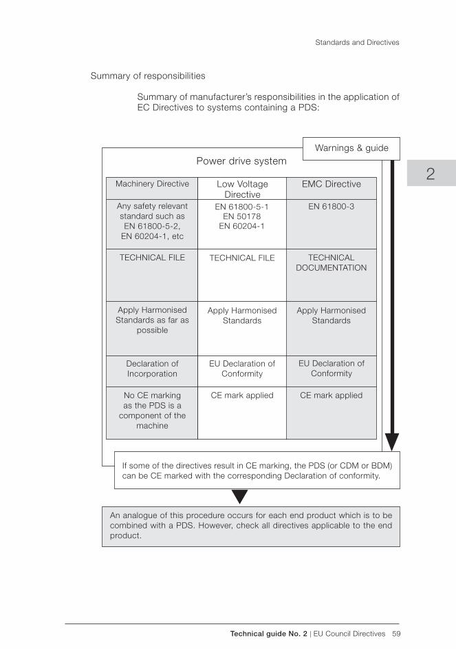
Technical guide No. 2 | EU Council Directives 59
2
Summary of responsibilities
Summary of manufacturer’s responsibilities in the application of EC Directives to systems containing a PDS:
If some of the directives result in CE marking, the PDS (or CDM or BDM) can be CE marked with the corresponding Declaration of conformity.
Warnings & guide Power drive system
Machinery Directive Low Voltage Directive
EMC Directive
Any safety relevant standard such as EN 61800-5-2,
EN 60204-1, etc
TECHNICAL FILE
Apply Harmonised Standards as far as
possible
Declaration of Incorporation
No CE marking as the PDS is a
component of the machine
EN 61800-5-1EN 50178
EN 60204-1
EN 61800-3
TECHNICAL FILE TECHNICAL DOCUMENTATION
Apply Harmonised Standards
Apply Harmonised Standards
EU Declaration of Conformity
EU Declaration of Conformity
CE mark applied CE mark applied
An analogue of this procedure occurs for each end product which is to be combined with a PDS. However, check all directives applicable to the end product.
Standards and Directives
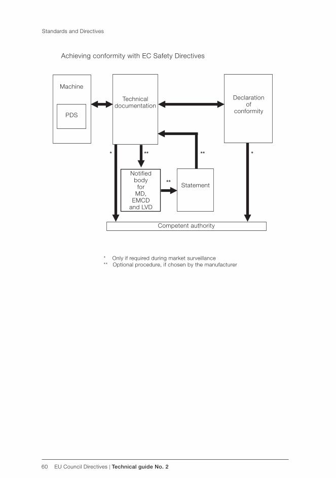
60 EU Council Directives | Technical guide No. 2
Achieving conformity with EC Safety Directives
Machine
PDS
Declaration of
conformity
Technical documentation
Competent authority
Statement
* Only if required during market surveillance** Optional procedure, if chosen by the manufacturer
*
**
Notified bodyfor
MD,EMCD
and LVD
** ** *
Standards and Directives
Technical guide No. 2 | EU Council Directives 61
2
Index
LLow Voltage Directive 11, 56, 57, 59
Mmachine builder 23, 24, 25, 40, 41, 46machinery builder 35Machinery Directive 11, 40, 41, 46, 55, 59MCC 37microprocessor 12mobile radio transmitters 12motor 22motor control centre 37
Nnotified body 40, 41
OOEM 24overload current 27
Ppanel builder 23, 24, 32parameters 16PDS 21, 22, 23, 24, 25, 26, 27, 28, 29, 30, 31, 32, 33, 34, 35, 48, 57, 59, 60phase-shift transformer 21portable car telephones 12power drive system 22, 59
Ssafety component 40, 41, 46screen 12self certification 15, 16, 37sensor 22short circuit 27single functional unit 29, 30standards 39, 40, 46, 48, 50, 51system designer 23, 24, 30, 35systems 1, 3, 9, 12, 13, 21, 48, 50, 51, 53, 55, 57, 59
TTD 33, 35, 36, 38technical construction file 38technical documentation 15, 28, 29, 30, 33, 34, 35, 36, 37, 39, 42, 47, 48technical file 27, 59, 60type certificate 27type certification 46type examination certificate 46
Wwalkie-talkies 12
Aabnormal temperatures 27apparatus 34, 38
Bbasic drive module 22BDM 22, 31, 32, 35, 57, 59
CCDM 22CE mark 32, 34, 59CEN 48, 49CENELEC 48, 49certificate of adequacy 41competent authority 47, 60complete drive module 22components 30, 34component supplier 29, 30, 33conducted emissions 51control circuit diagrams 40
DDeclaration of conformity 29, 30, 31, 34, 57, 59Declaration of incorporation 34, 35, 59distributor 24drive 22, 24
EEEA 11, 15, 47, 48, 57electrical safety 25, 26, 31, 32, 50electromagnetic compatibility 53EMC 11, 29, 30, 33, 36, 39, 57, 59EMC Directive 30EN61800-3 33, 50end user 23, 24ETSI 48EU 11, 49, 59EU Council Directives 1, 11European Union 48
FFaraday cage 51filter 30, 33frequency converter 21, 58
Hharmonics 9, 50harmonised standard 48, 49
IIEC 49indirect contact 26installation 22installation guidelines 29, 30installation instructions 18installer 24

62 EU Council Directives | Technical guide No. 2

3AFE
6125
3980
RE
V E
EN
8.2
.201
3 #1
6675
Contact us
For more information please contact your local ABB representative or visit:
www.abb.com/driveswww.abb.com/drivespartners
© Copyright 2013 ABB. All rights reserved. Specifications subject to change without notice.

Technical guide No. 3EMC compliant installation and configuration for a power drive system
ABB drives

2 EMC compliant installation and configuration for a PDS | Technical guide No. 3

Technical guide No. 3 | EMC compliant installation and configuration for a PDS 3
© Copyright 2012 ABB. All rights reserved.
Specifications subject to change without notice.
3AFE61348280 REV D 8.6.2012
Technical guide No. 3EMC compliant installation and configuration for a power drive system
3

4 EMC compliant installation and configuration for a PDS | Technical guide No. 3
Technical guide No. 3 | EMC compliant installation and configuration for a PDS 5
3
Contents
Chapter 1 - Introduction ............................................................................7
General ..............................................................................................7Purpose of this guide ..........................................................................7Directives concerning the drive ...........................................................7Who is the manufacturer? ...................................................................7Manufacturer’s responsibility ...............................................................7OEM customer as a manufacturer .......................................................8Panel builder or system integrator as a manufacturer ...........................8Definitions ..........................................................................................8Practical installations and systems ......................................................8Earthing principles ..............................................................................9Product-specific manuals ....................................................................9
Chapter 2 - Definitions .............................................................................10
Electromagnetic compatibility (EMC) of PDS ......................................10Immunity ..........................................................................................10Emission ..........................................................................................10Power drive system ..........................................................................11Types of equipment ..........................................................................12Components or sub-assemblies intended for incorporation ................12into an apparatus by the end users ...................................................12Components or sub-assemblies intended for incorporation ................12into an apparatus by other manufacturers or assemblers ....................12Finished appliance ............................................................................13Finished appliance intended for end users .........................................13Finished appliance intended for other manufacturer or assembler .......13Systems (combination of finished appliances) ....................................14Apparatus ........................................................................................14Fixed installation ...............................................................................14Equipment .......................................................................................14CE marking for EMC .........................................................................14Installation environments ...................................................................15First environment ..............................................................................15Second environment .........................................................................16EMC emission limits .........................................................................16
PDS of category C1 .....................................................................16PDS of category C2 .....................................................................16PDS of category C3 .....................................................................16PDS of category C4 .....................................................................17
Chapter 3 - EMC solutions.......................................................................19
General ............................................................................................19Solutions for EMC compatibility .........................................................19Emissions ........................................................................................19
6 EMC compliant installation and configuration for a PDS | Technical guide No. 3
Conducted emission .........................................................................19Radiated emission ............................................................................20
Enclosure ....................................................................................20Cabling and wiring .......................................................................20Installation ...................................................................................21
Clean and dirty side ..........................................................................21RFI filtering .......................................................................................22Selecting the RFI filter .......................................................................23Installation of the RFI filter .................................................................23Selection of a secondary enclosure ...................................................23Holes in enclosures ..........................................................................24360° HF earthing ..............................................................................25HF earthing with cable glands ...........................................................25HF earthing with conductive sleeve ...................................................26360° earthing at motor end ...............................................................27Conductive gaskets with control cables .............................................28The shielding should be covered with conductive tape. ......................28Installation of accessories .................................................................29Internal wiring ...................................................................................29Control cables and cabling ................................................................31Power cables ...................................................................................32Transfer impedance ..........................................................................33Use of ferrite rings ............................................................................33Simple installation.............................................................................35Typical installation .............................................................................35
Chapter 4 - Practical examples ...............................................................35
Example of by-pass system <100 kVA ...............................................36Typical example of 12-pulse drive ......................................................37Example of EMC plan .......................................................................39
Chapter 5 - Bibliography .........................................................................41
Chapter 6 - Index .....................................................................................42
Technical guide No. 3 | EMC compliant installation and configuration for a PDS 7
3
Chapter 1 - Introduction
General
This guide assists design and installation personnel when trying to ensure compliance with the radio frequency requirements of the EMC Directive in the user’s systems and installations when using AC drives. The radio frequency range starts from 9 kHz. However, most standards at the moment deal with frequencies that are higher than 150 kHz.
The frequency range below 9 kHz, that is, harmonics, is dealt with technical guide No. 6 “Guide to harmonics with AC drives”.
Purpose of this guide
The purpose of this guide is to guide original equipment manufac-turers (OEM), system integrators and panel builders ( assemblers) in designing or installing AC drive products and their auxiliary components into their own installations and systems. The aux-iliaries include contactors, switches, fuses, etc. By following these instructions it is possible to fulfill EMC requirements and give CE marking when necessary.
Directives concerning the drive
There are three directives that concern variable speed drives. They are the Machinery Directive, Low Voltage Directive and EMC Directive. The requirements and principles of the directives and use of CE marking are described in technical guide No. 2 “EU Council Directives and adjustable electrical power drive systems”. This document deals only with the EMC Directive.
Who is the manufacturer?
According to the EMC Directive (2004/108/EC), the definition of a manufacturer is following: “This is the person responsible for the design and construction of an apparatus covered by the Directive with a view to placing it on the EEA market on his own behalf. Whoever modifies substantially an apparatus resulting in an “as-new” apparatus, with a view to placing it on the EEA market, also becomes the manufacturer.”
8 EMC compliant installation and configuration for a PDS | Technical guide No. 3
Manufacturer’s responsibility
According to the EMC Directive the manufacturer is responsible for attaching the CE mark to each unit. Equally the manufacturer is responsible for writing and maintaining technical documenta-tion (TD).
OEM customer as a manufacturer
It is well known that OEM customers sell equipment using their own trademarks or brand labels. Changing the trademark, brand label or the type marking is an example of modification resulting in “as new” equipment.
Frequency converters sold as OEM products shall be considered components ( complete drive module (CDM) or basic drive module (BDM)). Apparatus is an entity and includes any documentation (manuals) intended for the final customer. Thus, the OEM-cus-tomer has sole and ultimate responsibility concerning the EMC of equipment, and he shall issue a Declaration of Conformity and technical documentation for the equipment.
Panel builder or system integrator as a manufacturer
According to the EMC Directive, a system is defined as a com-bination of several types of equipment, finished products, and/or components combined, designed and/or put together by the same person ( system manufacturer) intended to be placed on the market for distribution as a single functional unit for an end- user and intended to be installed and operated together to perform a specific task.
A panel builder or system integrator typically undertakes this kind of work. Thus, the panel builder or system integrator has sole and ultimate responsibility concerning the EMC of the system. He cannot pass this responsibility to a supplier.
In order to help the panel builder/system integrator, ABB Oy offers installation guidelines related to each product as well as general EMC guidelines (this document).
Definitions
The EMC Product Standard for Power Drive Systems, EN 61800-3 (or IEC 61800-3) is used as the main standard for variable speed drives. The terms and definitions defined in the standard are also used in this guide.
Introduction
Technical guide No. 3 | EMC compliant installation and configuration for a PDS 9
3
Practical installations and systems
This guide gives practical EMC examples and solutions that are not described in product specific manuals. The solutions can be directly used or applied by the OEM or panel builder.
Earthing principles
The earthing and cabling principles of variable speed drives are described in the manual “Grounding and cabling of the drive system”, code 3AFY61201998. It also includes a short descrip-tion of interference phenomena.
Product-specific manuals
Detailed information on the installation and use of products, cable sizes etc. can be found in the product specific manuals. This guide is intended to be used together with product specific manuals.
Introduction
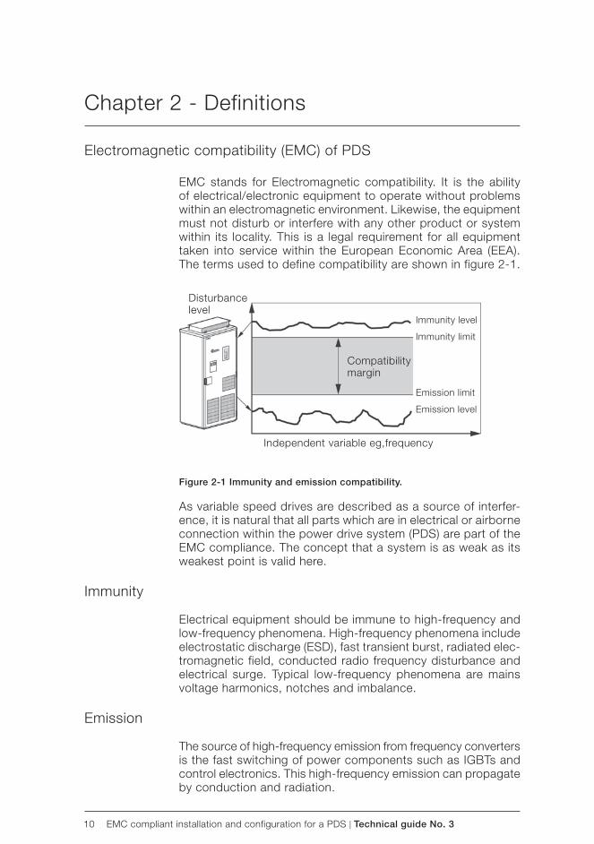
10 EMC compliant installation and configuration for a PDS | Technical guide No. 3
Disturbance level
Independent variable eg,frequency
Immunity level
Immunity limit
Emission limit
Emission level
Compatibility margin
Chapter 2 - Definitions
Electromagnetic compatibility (EMC) of PDS
EMC stands for Electromagnetic compatibility. It is the ability of electrical/electronic equipment to operate without problems within an electromagnetic environment. Likewise, the equipment must not disturb or interfere with any other product or system within its locality. This is a legal requirement for all equipment taken into service within the European Economic Area ( EEA). The terms used to define compatibility are shown in figure 2-1.
Figure 2-1 Immunity and emission compatibility.
As variable speed drives are described as a source of interfer-ence, it is natural that all parts which are in electrical or airborne connection within the power drive system (PDS) are part of the EMC compliance. The concept that a system is as weak as its weakest point is valid here.
Immunity
Electrical equipment should be immune to high-frequency and low-frequency phenomena. High-frequency phenomena include electrostatic discharge (ESD), fast transient burst, radiated elec-tromagnetic field, conducted radio frequency disturbance and electrical surge. Typical low-frequency phenomena are mains voltage harmonics, notches and imbalance.
Emission
The source of high-frequency emission from frequency converters is the fast switching of power components such as IGBTs and control electronics. This high-frequency emission can propagate by conduction and radiation.
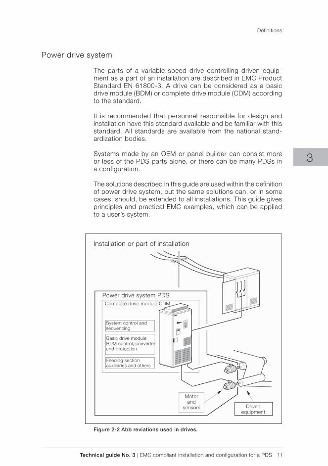
Technical guide No. 3 | EMC compliant installation and configuration for a PDS 11
Installation or part of installation
Power drive system PDS
Basic drive moduleBDM control, converter and protection
Feeding sectionauxiliaries and others
Motorand
sensors Drivenequipment
Complete drive module CDM
System control andsequencing
3
Power drive system
The parts of a variable speed drive controlling driven equip-ment as a part of an installation are described in EMC Product Standard EN 61800-3. A drive can be considered as a basic drive module (BDM) or complete drive module (CDM) according to the standard.
It is recommended that personnel responsible for design and installation have this standard available and be familiar with this standard. All standards are available from the national stand-ardization bodies.
Systems made by an OEM or panel builder can consist more or less of the PDS parts alone, or there can be many PDSs in a configuration.
The solutions described in this guide are used within the definition of power drive system, but the same solutions can, or in some cases, should, be extended to all installations. This guide gives principles and practical EMC examples, which can be applied to a user’s system.
Figure 2-2 Abb reviations used in drives.
Definitions
12 EMC compliant installation and configuration for a PDS | Technical guide No. 3
Types of equipment
The EMC Directive (2004/108/EC) defines equipment as any ap-paratus or fixed installation. As there are separate provisions for apparatus and fixed installations, it is important that the correct category of the equipment (PDM, CDM or BDM) is determined.
In technical-commercial classifications the following terminol-ogy is frequently used: components, sub-assemblies, finished appliances (ie, finished products), a combination of finished appliances (ie, a system), apparatus, fixed installations and equipment.
The key issue here is whether the item is meant for end users or not:
– if it is meant for end users, the EMC directive applies; – if it is meant for manufacturers or assemblers, the EMC
directive does not apply.
Components or sub-assemblies intended for incorporationinto an apparatus by the end users
A manufacturer may place components or sub-assemblies on the market, which are:
– for incorporation into an apparatus by the end-user, – available to end-users and likely to be used by them.
These components or sub-assemblies are to be considered as apparatus with regard to the application of the EMC. The instruc-tions for use accompanying the component or sub-assembly should include all relevant information, and should assume that adjustments or connections can be performed by an end user not aware of the EMC implications.
Some variable speed power drive products fall into this category, eg, a drive with enclosure and sold as a complete unit (CDM) to the end user who installs it into his own system. All provisions of the EMC Directive will apply ( CE mark, EC declaration of conformity and technical documentation).
Components or sub-assemblies intended for incorporationinto an apparatus by other manufacturers or assemblers
Components or sub-assemblies intended for incorporation into an apparatus or another sub-assembly by other manufacturers or assemblers are not considered to be “apparatus” and are therefore not covered by the EMC Directive. These components include resistors, cables, terminal blocks, etc.
Definitions
Technical guide No. 3 | EMC compliant installation and configuration for a PDS 13
3
Some variable speed power drive products fall into this category as well, eg, basic drive modules (BDM). These are meant to be assembled by a professional assembler (eg, panel builder or system manufacturer) into a cabinet not in the scope of delivery of the manufacturer of the BDM. According to the EMC Directive, the requirement for the BDM supplier is to provide instructions for installation and use.
Note:The manufacturer or assembler of the panel or system is respon-sible for the CE mark, the EC Declaration of Conformity, and the technical documentation.
Finished appliance
A finished appliance is any device or unit containing electrical and/or electronic components or sub-assemblies that delivers a function and has its own enclosure. Similarly to components, the interpretation “finished appliance” can be divided into two categories: it can be intended for end users, or for other manu-facturers or assemblers.
Finished appliance intended for end users
A finished appliance is considered as apparatus in the sense of the EMC Directive if it is intended for the end-user and thus has to fulfill all the applicable provisions of the Directive.
Variable speed power drive products that fall into this category are whole power drive systems (PDS) or complete drive mod-ules (CDM). In this case all provisions of the EMC Directive will apply (CE mark, EC Declaration of Conformity, and technical documentation). The drive product manufacturer is responsible for the CE mark, EC Declaration of Conformity, and technical documentation.
Finished appliance intended for other manufacturer or assembler
When the finished appliance is intended exclusively for an in-dustrial assembly operation for incorporation into other appa-ratus, it is not an apparatus in the sense of the EMC Directive and consequently the EMC Directive does not apply for such finished appliances.
The variable speed power drive products that fall into this cat-egory are basic drive modules (BDM). The approach is the same as for components or sub-assemblies when they are intended for incorporation into an apparatus by another manufacturer or assembler. Thus the manufacturer or assembler of the panel or system is responsible for all actions relating to the EMC Directive.
Definitions
14 EMC compliant installation and configuration for a PDS | Technical guide No. 3
Systems (combination of finished appliances)
A combination of several finished appliances which is combined, and/or designed and/or put together by the same party (ie, the system manufacturer) and is intended to be placed on the market for distribution as a single functional unit for an end- user and intended to be installed and operated together to perform a specific task.
All provisions of the EMC Directive, as defined for apparatus, apply to the combination as a whole. The variable speed power drive products that fall into this category are power drive systems (PDS). Thus the manufacturer of the PDS is responsible for all actions relating to the EMC Directive.
Apparatus
Apparatus means any finished appliance or combination thereof made commercially available (ie, placed on the market) as a single functional unit, intended for the end-user, and liable to generate electromagnetic disturbance, or the performance of which is liable to be affected by such disturbance.
Fixed installation
A particular combination of several types of apparatus, equip-ment and/or components, which are assembled, installed and intended to be used permanently at a predefined location.
Equipment
Any apparatus or fixed installation
CE marking for EMC
Components or sub-assemblies intended for incorporation into an apparatus by the end users need to carry the CE marking for EMC.
Components or sub-assemblies intended for incorporation into an apparatus by another manufacturer or assembler do not need to carry the CE marking for EMC.Note: The products may carry the CE marking for other direc-tives than EMC.
Definitions
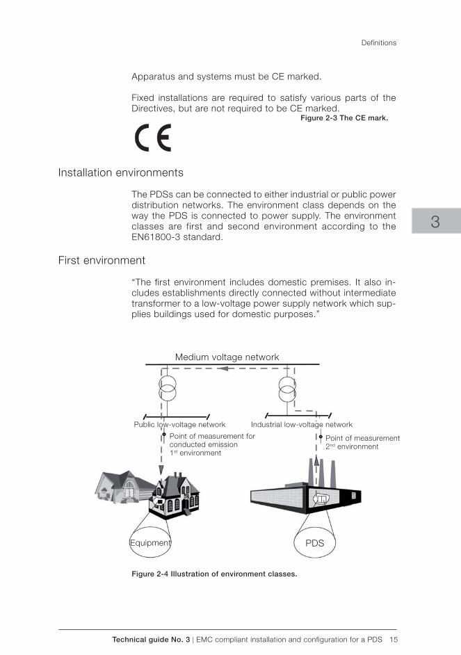
Technical guide No. 3 | EMC compliant installation and configuration for a PDS 15
Medium voltage network
Point of measurement for conducted emission1st environment
Equipment PDS
Public low-voltage network Industrial low-voltage network
Point of measurement2nd environment
3
Apparatus and systems must be CE marked.
Fixed installations are required to satisfy various parts of the Directives, but are not required to be CE marked.
Figure 2-3 The CE mark.
Installation environments
The PDSs can be connected to either industrial or public power distribution networks. The environment class depends on the way the PDS is connected to power supply. The environment classes are first and second environment according to the EN61800-3 standard.
First environment
“The first environment includes domestic premises. It also in-cludes establishments directly connected without intermediate transformer to a low-voltage power supply network which sup-plies buildings used for domestic purposes.”
Figure 2-4 Illustration of environment classes.
Definitions
16 EMC compliant installation and configuration for a PDS | Technical guide No. 3
Second environment
“The second environment includes all establishments other than those directly connected to a low-voltage power supply network which supplies buildings used for domestic purposes”.
EMC emission limits
The product standard EN 61800-3 divides PDSs into four cat-egories according to the intended use. In Europe, the standard takes precedence over all generic or product family EMC stand-ards previously applicable. Limits for certain conditions can be selected by using the flow chart shown in figure 2-5.
PDS of category C1
A PDS (or CDM) with rated voltage less than 1000 V and intended for use in the first environment. A PDS (or CDM) sold “as built” to the end user.
The PDS manufacturer is responsible for the EMC behavior of the PDS under specified conditions. Additional EMC measures are described in an easy-to-understand way and can be imple-mented by a layman.
When PDS/CDM is to be incorporated with another product, the resulting EMC behavior of that product is the responsibility of the assembler of the final product, by following the manufacturer’s recommendations and guidelines.
PDS of category C2
A PDS (or CDM/BDM) with rated voltage less than 1,000 V, which is neither a plug in device nor a movable device and is intended to be installed and commissioned only by a professional. A PDS (or CDM/BDM) sold to be incorporated into an apparatus, system or installation.
When a PDS/CDM/BDM is to be incorporated with another product, the resulting EMC behavior of that product is the re-sponsibility of the assembler of the final product.
PDS of category C3
A PDS (or CDM/BDM) with rated voltage less than 1,000 V, intended for use in the second environment. A PDS (or CDM/BDM) sold “as built” to the end user or in order to be incorporated into an apparatus, system or installation.
Definitions
Technical guide No. 3 | EMC compliant installation and configuration for a PDS 17
3
The PDS manufacturer is responsible for the EMC behavior of the PDS under specified conditions. Additional EMC measures are described in an easy-to-understand way and can be imple-mented by a layman.
When a PDS/CDM is to be incorporated with another product, the resulting EMC behavior of that product is the responsibility of the assembler of the final product, by following the manufac-turer’s recommendations and guidelines.
PDS of category C4
A PDS (or CDM/BDM) with rated voltage equal to or above 1,000 V, or rated current equal to or above 400 A, or intended for use in complex systems in the second environment. A PDS (or CDM/BDM) sold to be incorporated into an apparatus, system or installation.
Category C4 requirements include all other EMC requirements except for radio frequency emission. They are assessed only when it is installed in its intended location. Therefore a category C4 PDS is treated as a fixed installation, and thus has no re-quirement for an EC Declaration of Conformity or CE Marking.
The EMC directive requires the accompanying documentation to identify the fixed installation, its electromagnetic compatibility characteristics and the person responsible, and to indicate the precautions to be taken in order not to compromise the conform-ity of that installation.
In order to comply with the above requirements in the case of a category C4 PDS (or CDM/BDM), the user and the manufacturer shall agree on an EMC plan to meet the EMC requirements for the intended application. In this situation, the user defines the EMC characteristics of the environment including the whole installa-tion and the neighborhood. The PDS manufacturer shall provide information on typical emission levels and installation guidelines for the PDS to be installed. The resulting EMC behavior is the responsibility of the installer (eg, by following the EMC plan).
Where there are indications of non-compliance of the category C4 PDS after commissioning, the standard includes a procedure for measuring the emission limits outside the boundary of an installation.
Definitions
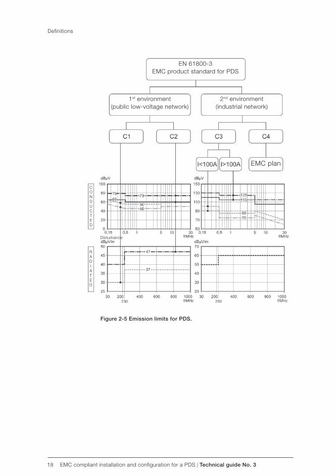
18 EMC compliant installation and configuration for a PDS | Technical guide No. 3
EN 61800-3EMC product standard for PDS
1st environment(public low-voltage network)
2nd environment(industrial network)
EMC plan
CONDUCTED
RADIATED
Disturbance
Figure 2-5 Emission limits for PDS.
Definitions
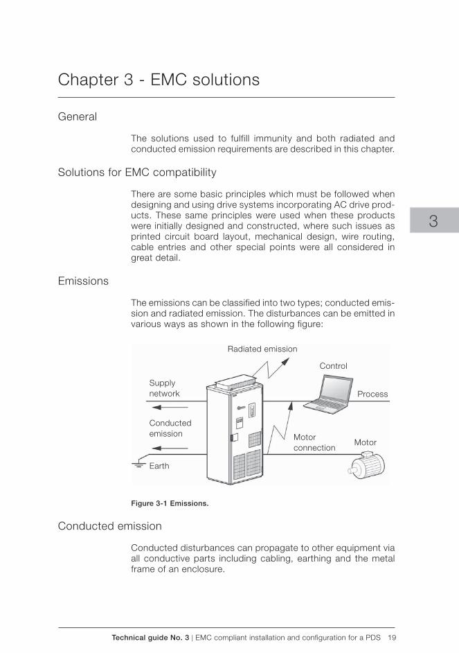
Technical guide No. 3 | EMC compliant installation and configuration for a PDS 19
Radiated emission
Supplynetwork
Conductedemission
Earth
Control
Process
Motorconnection
Motor
3
Chapter 3 - EMC solutions
General
The solutions used to fulfill immunity and both radiated and conducted emission requirements are described in this chapter.
Solutions for EMC compatibility
There are some basic principles which must be followed when designing and using drive systems incorporating AC drive prod-ucts. These same principles were used when these products were initially designed and constructed, where such issues as printed circuit board layout, mechanical design, wire routing, cable entries and other special points were all considered in great detail.
Emissions
The emissions can be classified into two types; conducted emis-sion and radiated emission. The disturbances can be emitted in various ways as shown in the following figure:
Figure 3-1 Emissions.
Conducted emission
Conducted disturbances can propagate to other equipment via all conductive parts including cabling, earthing and the metal frame of an enclosure.
20 EMC compliant installation and configuration for a PDS | Technical guide No. 3
Conductive emissions can be reduced in the following way:
– By RFI filtering for HF disturbances – Using ferrite rings in power connection points – Using an AC or DC choke (even meant against harmonics,
it reduce HF disturbances as well. – Using an LCL filter in the case of regenerative drives – Using a du/dt filter
Radiated emission
To be able to effectively prevent disturbance through the air, all parts of the power drive system should form a Faraday cage against radiated emissions. The installation of a PDS includes cabinets, auxiliary boxes, cabling, motors, etc.
Some methods for ensuring the continuity of the Faraday cage are listed as follows:
Enclosure
– The enclosure must have an unpainted non-corroding surface finish at every point where other plates, doors, etc. make contact.
– Unpainted metal-to-metal contacts shall be used throughout, with conductive gaskets, where appropriate.
– Use unpainted installation plates, bonded to a common earth point, ensuring all separate metal items are firmly bonded to achieve a single path to earth.
– Use conductive gaskets in doors and covers. Separate the radiative ie, “dirty” side from the “clean side” by metal covers and design.
– Holes in enclosure should be minimized.
Cabling and wiring
– Use special HF cable entries for high frequency earthing of power cable shields.
– Use conductive gaskets for HF earthing of control cable shield.
– Use shielded power and control cables. See product specific manuals.
– Allow no breaks in the cable shields. – Select shield connections with low impedance on the MHz
range. – Route power and control cables separately. – Use twisted pairs to avoid disturbances. – Use ferrite rings for disturbances, if necessary. – Select and route internal wires correctly. – See product specific manuals.
EMC solutions
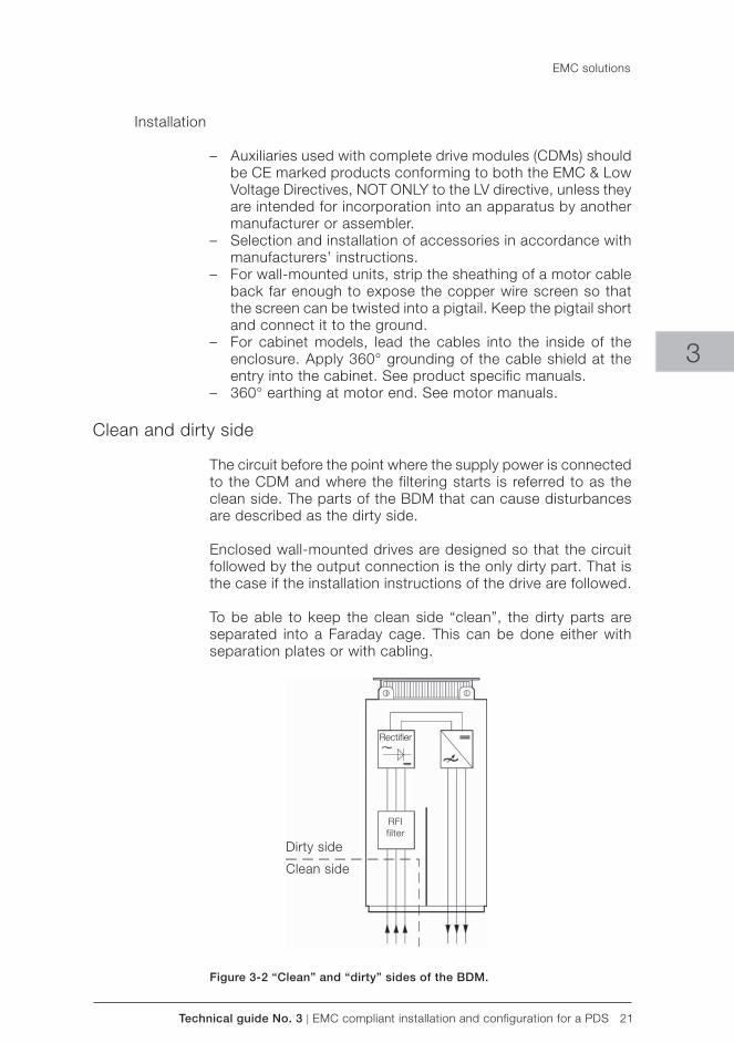
Technical guide No. 3 | EMC compliant installation and configuration for a PDS 21
Rectifi er
RFIfilter
Dirty side
Clean side
3
Installation
– Auxiliaries used with complete drive modules (CDMs) should be CE marked products conforming to both the EMC & Low Voltage Directives, NOT ONLY to the LV directive, unless they are intended for incorporation into an apparatus by another manufacturer or assembler.
– Selection and installation of accessories in accordance with manufacturers’ instructions.
– For wall-mounted units, strip the sheathing of a motor cable back far enough to expose the copper wire screen so that the screen can be twisted into a pigtail. Keep the pigtail short and connect it to the ground.
– For cabinet models, lead the cables into the inside of the enclosure. Apply 360° grounding of the cable shield at the entry into the cabinet. See product specific manuals.
– 360° earthing at motor end. See motor manuals.
Clean and dirty side
The circuit before the point where the supply power is connected to the CDM and where the filtering starts is referred to as the clean side. The parts of the BDM that can cause disturbances are described as the dirty side.
Enclosed wall-mounted drives are designed so that the circuit followed by the output connection is the only dirty part. That is the case if the installation instructions of the drive are followed.
To be able to keep the clean side “clean”, the dirty parts are separated into a Faraday cage. This can be done either with separation plates or with cabling.
Figure 3-2 “Clean” and “dirty” sides of the BDM.
EMC solutions
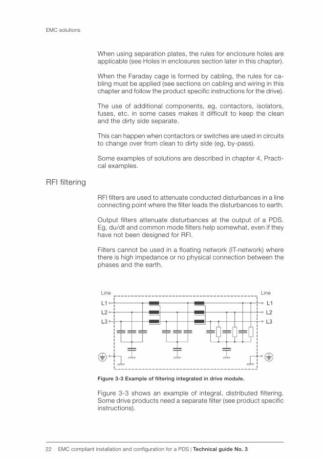
22 EMC compliant installation and configuration for a PDS | Technical guide No. 3
Line Line
When using separation plates, the rules for enclosure holes are applicable (see Holes in enclosures section later in this chapter).
When the Faraday cage is formed by cabling, the rules for ca-bling must be applied (see sections on cabling and wiring in this chapter and follow the product specific instructions for the drive).
The use of additional components, eg, contactors, isolators, fuses, etc. in some cases makes it difficult to keep the clean and the dirty side separate.
This can happen when contactors or switches are used in circuits to change over from clean to dirty side (eg, by-pass).
Some examples of solutions are described in chapter 4, Practi-cal examples.
RFI filtering
RFI filters are used to attenuate conducted disturbances in a line connecting point where the filter leads the disturbances to earth.
Output filters attenuate disturbances at the output of a PDS. Eg, du/dt and common mode filters help somewhat, even if they have not been designed for RFI.
Filters cannot be used in a floating network (IT-network) where there is high impedance or no physical connection between the phases and the earth.
Figure 3-3 Example of filtering integrated in drive module.
Figure 3-3 shows an example of integral, distributed filtering. Some drive products need a separate filter (see product specific instructions).
EMC solutions
Technical guide No. 3 | EMC compliant installation and configuration for a PDS 23
3
EMC solutions
Selecting the RFI filter
An RFI filter is selected to attenuate the conducted disturbances. It is not possible to compare the disturbances measured from a source, and the insertion loss for a filter, as the measurement base for the two items of information will not correspond.
It is always necessary to test a filter in conjunction with the source of disturbance to ensure adequate attenuation and to meet applicable emission limits.
Installation of the RFI filter
Reliable HF/low impedance connections are essential to ensure proper functioning of the filter, therefore the following instructions are to be followed. – The filter shall be assembled on a metal plate with unpainted
connection points all in accordance with the filter manufac-turer’s instructions.
– The orientation of the filter must be such that it provides enough distance between the input and output wiring of the filter in order to prevent cross-coupling between the clean and dirty side.
– The length of the cable between the filter and the drive must be minimized.
– The input cable of the filter shall be separated from the cable which connects the filter to the drive
– The input cable of the filter shall be separated from the mo-tor cable
Selection of a secondary enclosure
Where the BDM is to be installed, (eg, an IP00 open chassis converter), or if additional components are to be connected to the dirty side of an otherwise compliant unit, it is always neces-sary to provide an EMC enclosure.
For enclosed chassis modules where the motor connections are made directly to the converter output terminals and all the internal shielding parts are fitted, there are no requirements for special enclosures.
If drives are fitted with output switching devices, for example, then an EMC enclosure will be needed, as the integral Faraday cage will no longer apply.
As a reminder, EMC is only one part of enclosure selection. The enclosure is sized according to several criteria:
– Safety – Degree of protection (IP rating)
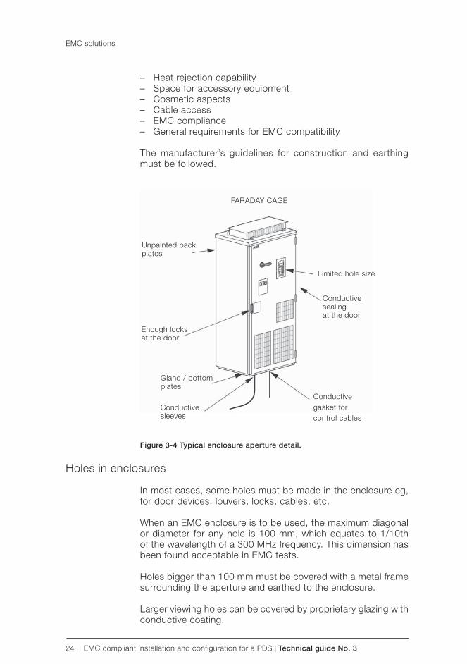
24 EMC compliant installation and configuration for a PDS | Technical guide No. 3
FARADAY CAGE
Unpainted backplates
Enough locksat the door
Gland / bottomplates
Conductivesleeves
Limited hole size
Conductivesealingat the door
Conductivegasket forcontrol cables
– Heat rejection capability – Space for accessory equipment – Cosmetic aspects – Cable access – EMC compliance – General requirements for EMC compatibility
The manufacturer’s guidelines for construction and earthing must be followed.
Figure 3-4 Typical enclosure aperture detail.
Holes in enclosures
In most cases, some holes must be made in the enclosure eg, for door devices, louvers, locks, cables, etc.
When an EMC enclosure is to be used, the maximum diagonal or diameter for any hole is 100 mm, which equates to 1/10th of the wavelength of a 300 MHz frequency. This dimension has been found acceptable in EMC tests.
Holes bigger than 100 mm must be covered with a metal frame surrounding the aperture and earthed to the enclosure.
Larger viewing holes can be covered by proprietary glazing with conductive coating.
EMC solutions
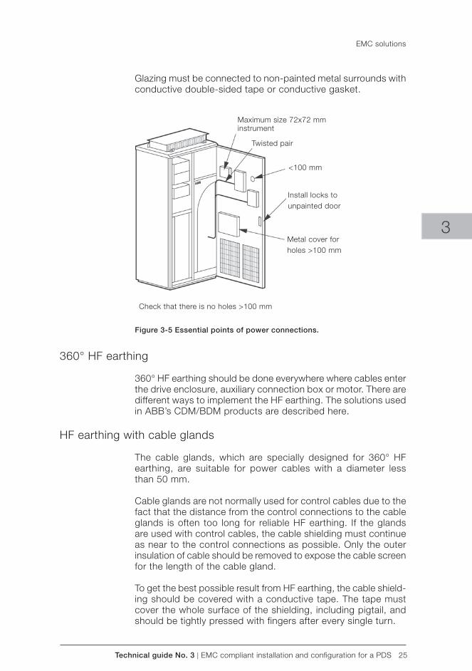
Technical guide No. 3 | EMC compliant installation and configuration for a PDS 25
Maximum size 72x72 mminstrument
Twisted pair
<100 mm
Install locks tounpainted door
Check that there is no holes >100 mm
Metal cover forholes >100 mm
3
Glazing must be connected to non-painted metal surrounds with conductive double-sided tape or conductive gasket.
Figure 3-5 Essential points of power connections.
360° HF earthing
360° HF earthing should be done everywhere where cables enter the drive enclosure, auxiliary connection box or motor. There are different ways to implement the HF earthing. The solutions used in ABB’s CDM/BDM products are described here.
HF earthing with cable glands
The cable glands, which are specially designed for 360° HF earthing, are suitable for power cables with a diameter less than 50 mm.
Cable glands are not normally used for control cables due to the fact that the distance from the control connections to the cable glands is often too long for reliable HF earthing. If the glands are used with control cables, the cable shielding must continue as near to the control connections as possible. Only the outer insulation of cable should be removed to expose the cable screen for the length of the cable gland.
To get the best possible result from HF earthing, the cable shield-ing should be covered with a conductive tape. The tape must cover the whole surface of the shielding, including pigtail, and should be tightly pressed with fingers after every single turn.
EMC solutions
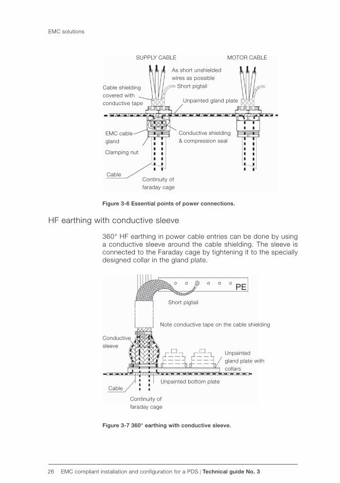
26 EMC compliant installation and configuration for a PDS | Technical guide No. 3
SUPPLY CABLE MOTOR CABLE
As short unshielded wires as possible
Cable shielding covered with conductive tape
EMC cable gland
Clamping nut
CableContinuity of faraday cage
Short pigtail
Unpainted gland plate
Conductive shielding & compression seal
Short pigtail
Note conductive tape on the cable shielding
Conductive sleeve
Cable
Continuity offaraday cage
Unpainted gland plate with collars
Unpainted bottom plate
Figure 3-6 Essential points of power connections.
HF earthing with conductive sleeve
360° HF earthing in power cable entries can be done by using a conductive sleeve around the cable shielding. The sleeve is connected to the Faraday cage by tightening it to the specially designed collar in the gland plate.
Figure 3-7 360° earthing with conductive sleeve.
EMC solutions
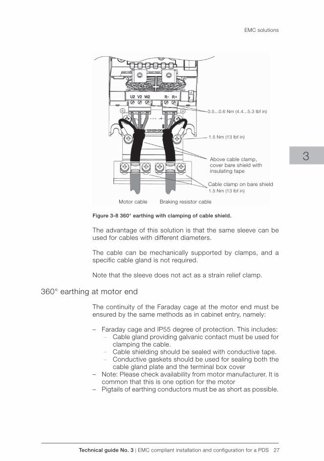
Technical guide No. 3 | EMC compliant installation and configuration for a PDS 27
Above cable clamp, cover bare shield with insulating tape
Cable clamp on bare shield
Motor cable Braking resistor cable
0.5...0.6 Nm (4.4...5.3 lbf in)
1.5 Nm (13 lbf in)
1.5 Nm (13 lbf in)
3
Figure 3-8 360° earthing with clamping of cable shield.
The advantage of this solution is that the same sleeve can be used for cables with different diameters.
The cable can be mechanically supported by clamps, and a specific cable gland is not required.
Note that the sleeve does not act as a strain relief clamp.
360° earthing at motor end
The continuity of the Faraday cage at the motor end must be ensured by the same methods as in cabinet entry, namely:
– Faraday cage and IP55 degree of protection. This includes: – Cable gland providing galvanic contact must be used for
clamping the cable. – Cable shielding should be sealed with conductive tape. – Conductive gaskets should be used for sealing both the
cable gland plate and the terminal box cover – Note: Please check availability from motor manufacturer. It is
common that this is one option for the motor – Pigtails of earthing conductors must be as short as possible.
EMC solutions
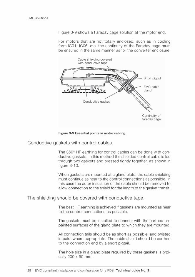
28 EMC compliant installation and configuration for a PDS | Technical guide No. 3
Cable shielding coveredwith conductive tape
Short pigtail
EMC cable gland
Continuity offaraday cage
Conductive gasket
Figure 3-9 shows a Faraday cage solution at the motor end.
For motors that are not totally enclosed, such as in cooling form IC01, IC06, etc. the continuity of the Faraday cage must be ensured in the same manner as for the converter enclosure.
Figure 3-9 Essential points in motor cabling.
Conductive gaskets with control cables
The 360° HF earthing for control cables can be done with con-ductive gaskets. In this method the shielded control cable is led through two gaskets and pressed tightly together, as shown in figure 3-10.
When gaskets are mounted at a gland plate, the cable shielding must continue as near to the control connections as possible. In this case the outer insulation of the cable should be removed to allow connection to the shield for the length of the gasket transit.
The shielding should be covered with conductive tape.
The best HF earthing is achieved if gaskets are mounted as near to the control connections as possible.
The gaskets must be installed to connect with the earthed un-painted surfaces of the gland plate to which they are mounted.
All connection tails should be as short as possible, and twisted in pairs where appropriate. The cable shield should be earthed to the connection end by a short pigtail.
The hole size in a gland plate required by these gaskets is typi-cally 200 x 50 mm.
EMC solutions
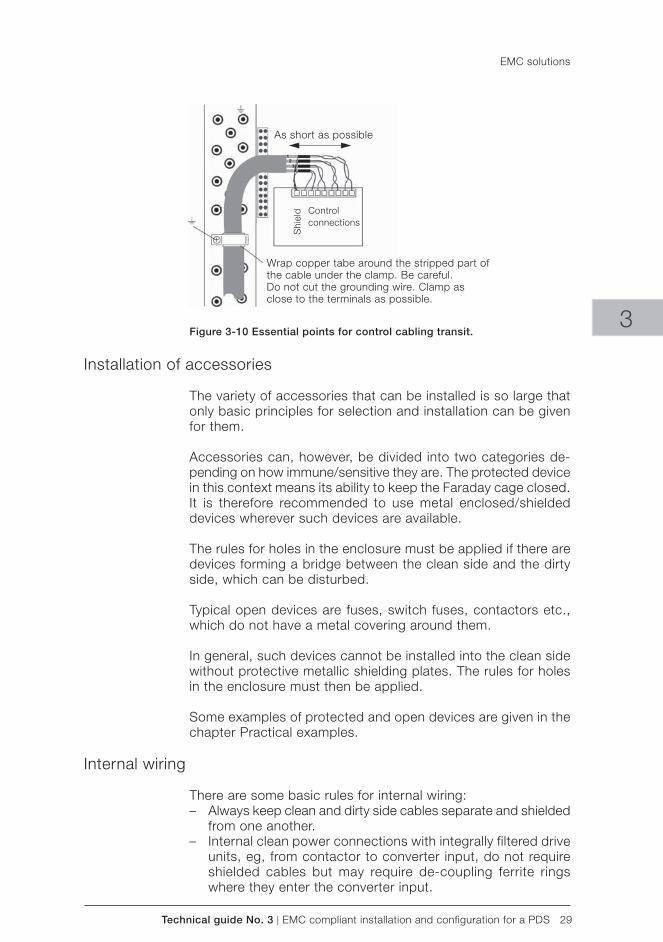
Technical guide No. 3 | EMC compliant installation and configuration for a PDS 29
As short as possible
Shi
eld Control
connections
Wrap copper tabe around the stripped part of the cable under the clamp. Be careful.Do not cut the grounding wire. Clamp as close to the terminals as possible.
3Figure 3-10 Essential points for control cabling transit.
Installation of accessories
The variety of accessories that can be installed is so large that only basic principles for selection and installation can be given for them.
Accessories can, however, be divided into two categories de-pending on how immune/sensitive they are. The protected device in this context means its ability to keep the Faraday cage closed. It is therefore recommended to use metal enclosed/shielded devices wherever such devices are available.
The rules for holes in the enclosure must be applied if there are devices forming a bridge between the clean side and the dirty side, which can be disturbed.
Typical open devices are fuses, switch fuses, contactors etc., which do not have a metal covering around them.
In general, such devices cannot be installed into the clean side without protective metallic shielding plates. The rules for holes in the enclosure must then be applied.
Some examples of protected and open devices are given in the chapter Practical examples.
Internal wiring
There are some basic rules for internal wiring: – Always keep clean and dirty side cables separate and shielded
from one another. – Internal clean power connections with integrally filtered drive
units, eg, from contactor to converter input, do not require shielded cables but may require de-coupling ferrite rings where they enter the converter input.
EMC solutions
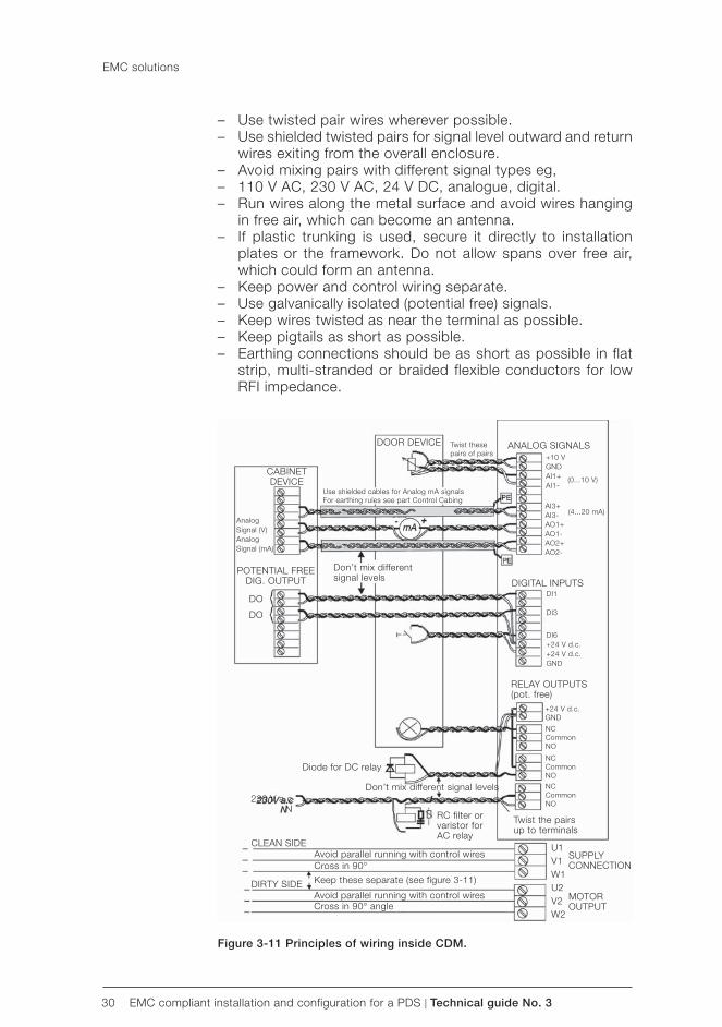
30 EMC compliant installation and configuration for a PDS | Technical guide No. 3
CABINETDEVICE
AnalogSignal (V)AnalogSignal (mA)
POTENTIAL FREE DIG. OUTPUT
DO
DO
DOOR DEVICE Twist thesepairs of pairs
Use shielded cables for Analog mA signalsFor earthing rules see part Control Cabing
Don’t mix differentsignal levels
Diode for DC relay
Don’t mix different signal levels
RC filter orvaristor forAC relay
CLEAN SIDE
DIRTY SIDE
Avoid parallel running with control wiresCross in 90°
Keep these separate (see figure 3-11)
Avoid parallel running with control wiresCross in 90° angle
SUPPLYCONNECTION
MOTOROUTPUT
Twist the pairsup to terminals
+24 V d.c.GND
NCCommonNO
NCCommonNO
NCCommonNO
RELAY OUTPUTS(pot. free)
ANALOG SIGNALS
DIGITAL INPUTSDI1
DI3
DI6+24 V d.c.+24 V d.c.GND
+10 VGNDAI1+AI1-
AI3+AI3-AO1+AO1-AO2+AO2-
(0...10 V)
(4...20 mA)
230 V a.cN
U1V1W1U2V2W2
– Use twisted pair wires wherever possible. – Use shielded twisted pairs for signal level outward and return
wires exiting from the overall enclosure. – Avoid mixing pairs with different signal types eg, – 110 V AC, 230 V AC, 24 V DC, analogue, digital. – Run wires along the metal surface and avoid wires hanging
in free air, which can become an antenna. – If plastic trunking is used, secure it directly to installation
plates or the framework. Do not allow spans over free air, which could form an antenna.
– Keep power and control wiring separate. – Use galvanically isolated (potential free) signals. – Keep wires twisted as near the terminal as possible. – Keep pigtails as short as possible. – Earthing connections should be as short as possible in flat
strip, multi-stranded or braided flexible conductors for low RFI impedance.
EMC solutions
Figure 3-11 Principles of wiring inside CDM.
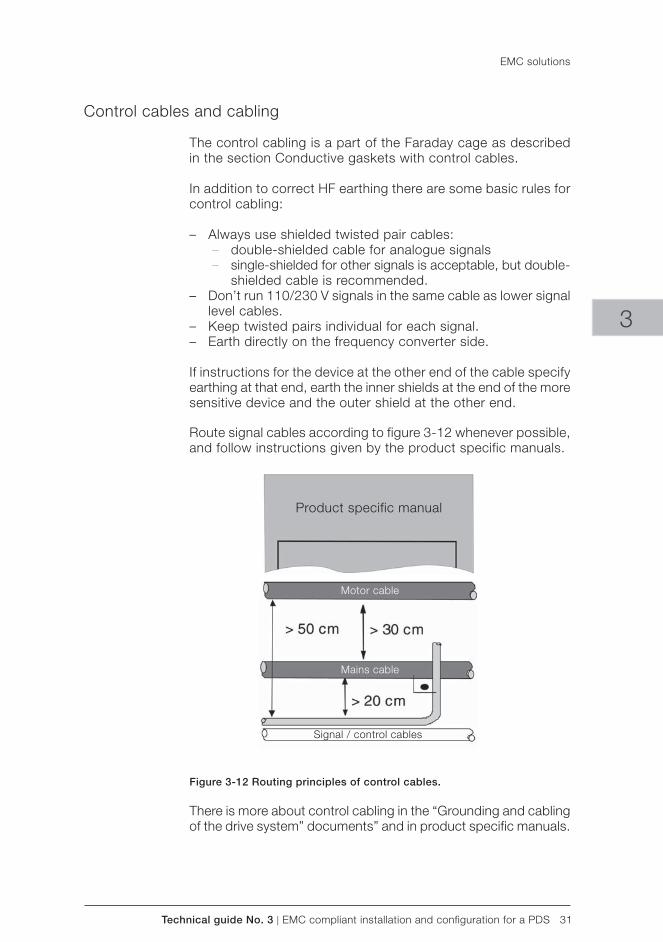
Technical guide No. 3 | EMC compliant installation and configuration for a PDS 31
Product specific manual
Motor cable
Mains cable
Signal / control cables
3
Control cables and cabling
The control cabling is a part of the Faraday cage as described in the section Conductive gaskets with control cables.
In addition to correct HF earthing there are some basic rules for control cabling:
– Always use shielded twisted pair cables: – double-shielded cable for analogue signals – single-shielded for other signals is acceptable, but double-
shielded cable is recommended. – Don’t run 110/230 V signals in the same cable as lower signal
level cables. – Keep twisted pairs individual for each signal. – Earth directly on the frequency converter side.
If instructions for the device at the other end of the cable specify earthing at that end, earth the inner shields at the end of the more sensitive device and the outer shield at the other end.
Route signal cables according to figure 3-12 whenever possible, and follow instructions given by the product specific manuals.
Figure 3-12 Routing principles of control cables.
There is more about control cabling in the “Grounding and cabling of the drive system” documents” and in product specific manuals.
EMC solutions
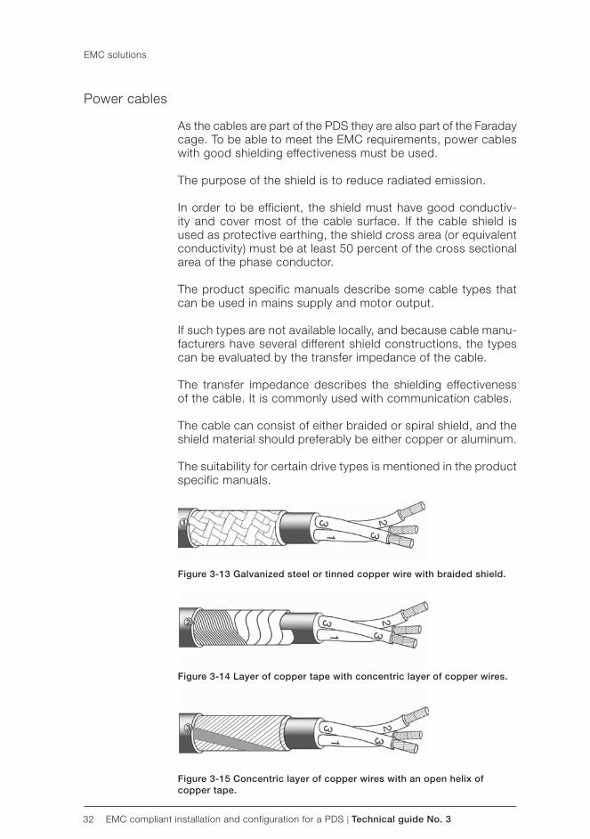
32 EMC compliant installation and configuration for a PDS | Technical guide No. 3
Power cables
As the cables are part of the PDS they are also part of the Faraday cage. To be able to meet the EMC requirements, power cables with good shielding effectiveness must be used.
The purpose of the shield is to reduce radiated emission.
In order to be efficient, the shield must have good conductiv-ity and cover most of the cable surface. If the cable shield is used as protective earthing, the shield cross area (or equivalent conductivity) must be at least 50 percent of the cross sectional area of the phase conductor.
The product specific manuals describe some cable types that can be used in mains supply and motor output.
If such types are not available locally, and because cable manu-facturers have several different shield constructions, the types can be evaluated by the transfer impedance of the cable.
The transfer impedance describes the shielding effectiveness of the cable. It is commonly used with communication cables.
The cable can consist of either braided or spiral shield, and the shield material should preferably be either copper or aluminum.
The suitability for certain drive types is mentioned in the product specific manuals.
Figure 3-13 Galvanized steel or tinned copper wire with braided shield.
Figure 3-14 Layer of copper tape with concentric layer of copper wires.
Figure 3-15 Concentric layer of copper wires with an open helix of copper tape.
EMC solutions
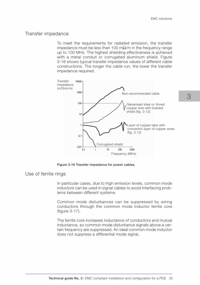
Technical guide No. 3 | EMC compliant installation and configuration for a PDS 33
Transferimpedance(mOhm/m)
Non-recommended cable
Galvanised steel or tinnedcopper wire with braided shield (fig. 3-12)
Layer of copper tabe withconcentric layer of copper wires (fig. 3.13)
Corrugated shield
Frequency (MHz)
3
EMC solutions
Transfer impedance
To meet the requirements for radiated emission, the transfer impedance must be less than 100 mΩ/m in the frequency range up to 100 MHz. The highest shielding effectiveness is achieved with a metal conduit or corrugated aluminum shield. Figure3-16 shows typical transfer impedance values of different cable constructions. The longer the cable run, the lower the transfer impedance required.
Figure 3-16 Transfer impedance for power cables.
Use of ferrite rings
In particular cases, due to high emission levels, common mode inductors can be used in signal cables to avoid interfacing prob-lems between different systems.
Common mode disturbances can be suppressed by wiring conductors through the common mode inductor ferrite core (figure 3-17).
The ferrite core increases inductance of conductors and mutual inductance, so common mode disturbance signals above a cer-tain frequency are suppressed. An ideal common mode inductor does not suppress a differential mode signal.

34 EMC compliant installation and configuration for a PDS | Technical guide No. 3
EMC solutions
Figure 3-17 Ferrite ring in signal wire.
The inductance (ie, the ability to suppress HF disturbances) can be increased by multiple turns of the signal wire.
When using a ferrite ring with power cable, all phase conductors should be led through the ring. The shielding and possible earth wire must be wired outside the ring to keep the common mode inductor effect. With power cables it is not normally possible to make multiple turns through the ring. The inductance can be increased by using several successive rings.
If for any reasons the installation instructions cannot be followed and therefore additional ferrites or filters are added afterwards, it is recommended that measurements be made to show con-formance.
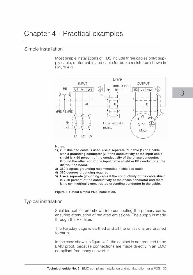
Technical guide No. 3 | EMC compliant installation and configuration for a PDS 35
DriveINPUT OUTPUT
External brakeresistor
Motor
3
Chapter 4 - Practical examples
Simple installation
Most simple installations of PDS include three cables only: sup-ply cable, motor cable and cable for brake resistor as shown in Figure 4-1.
Notes:1), 2) If shielded cable is used, use a separate PE cable (1) or a cable with a grounding conductor (2) if the conductivity of the input cable shield is < 50 percent of the conductivity of the phase conductor. Ground the other end of the input cable shield or PE conductor at the distribution board. 3) 360 degrees grounding recommended if shielded cable4) 360 degrees grounding required5) Use a separate grounding cable if the conductivity of the cable shield is < 50 percent of the conductivity of the phase conductor and there is no symmetrically constructed grounding conductor in the cable.
Figure 4-1 Most simple PDS installation.
Typical installation
Shielded cables are shown interconnecting the primary parts, ensuring attenuation of radiated emissions. The supply is made through the RFI filter.
The Faraday cage is earthed and all the emissions are drained to earth.
In the case shown in figure 4-2, the cabinet is not required to be EMC proof, because connections are made directly in an EMC compliant frequency converter.
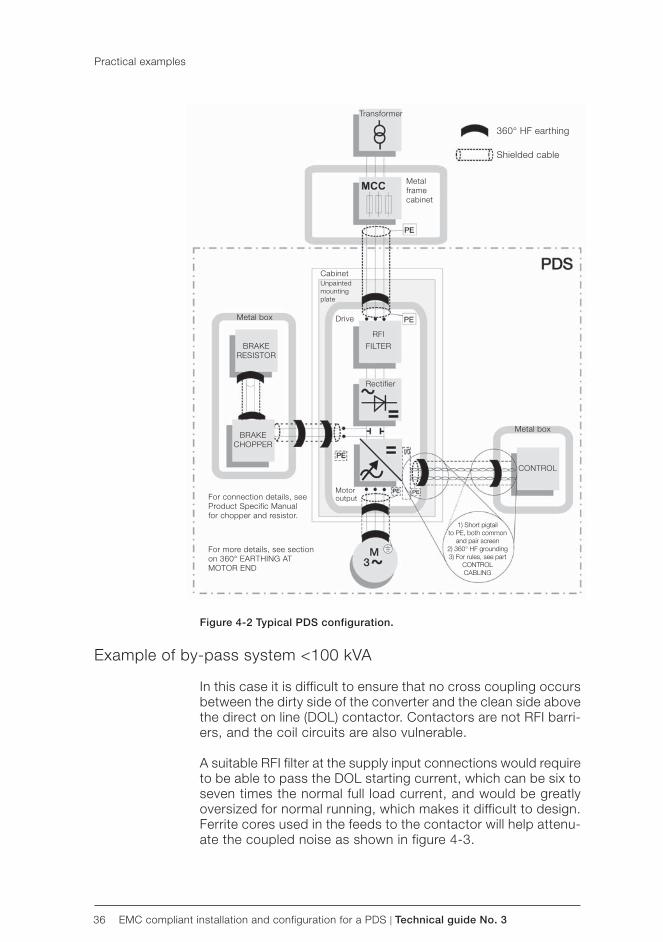
36 EMC compliant installation and configuration for a PDS | Technical guide No. 3
Transformer
360° HF earthing
Shielded cable
Metalframecabinet
CabinetUnpaintedmountingplate
Drive
RFI
FILTER
Metal box
Metal box
Rectifier
BRAKERESISTOR
BRAKECHOPPER
For connection details, seeProduct Specific Manualfor chopper and resistor.
For more details, see sectionon 360° EARTHING ATMOTOR END
CONTROL
1) Short pigtailto PE, both common
and pair screen2) 360° HF grounding3) For rules, see part
CONTROLCABLING
Motor output
Figure 4-2 Typical PDS configuration.
Example of by-pass system <100 kVA
In this case it is difficult to ensure that no cross coupling occurs between the dirty side of the converter and the clean side above the direct on line (DOL) contactor. Contactors are not RFI barri-ers, and the coil circuits are also vulnerable.
A suitable RFI filter at the supply input connections would require to be able to pass the DOL starting current, which can be six to seven times the normal full load current, and would be greatly oversized for normal running, which makes it difficult to design. Ferrite cores used in the feeds to the contactor will help attenu-ate the coupled noise as shown in figure 4-3.
Practical examples
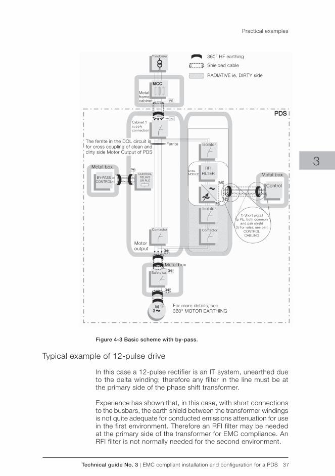
Technical guide No. 3 | EMC compliant installation and configuration for a PDS 37
Transformer 360° HF earthing
Shielded cable
RADIATIVE ie, DIRTY side
Cabinet 1supplyconnection
The ferrite in the DOL circuit isfor cross coupling of clean anddirty side Motor Output of PDS
Ferrite
Metal box
BY-PASSCONTROL
CONTROLRELAYSOR PLC
Contactor
Motoroutput
Metal box
Safety sw.
For more details, see360° MOTOR EARTHING
1) Short pigtailtp PE, both common
and pair shield3) For rules, see part
CONTROLCABLING
Isolator
Isolator
RFIFILTER
Contactor
Control
Metal boxDRIVEMODULE
Metalframecabinet
3
Practical examples
Figure 4-3 Basic scheme with by-pass.
Typical example of 12-pulse drive
In this case a 12-pulse rectifier is an IT system, unearthed due to the delta winding; therefore any filter in the line must be at the primary side of the phase shift transformer.
Experience has shown that, in this case, with short connections to the busbars, the earth shield between the transformer windings is not quite adequate for conducted emissions attenuation for use in the first environment. Therefore an RFI filter may be needed at the primary side of the transformer for EMC compliance. An RFI filter is not normally needed for the second environment.
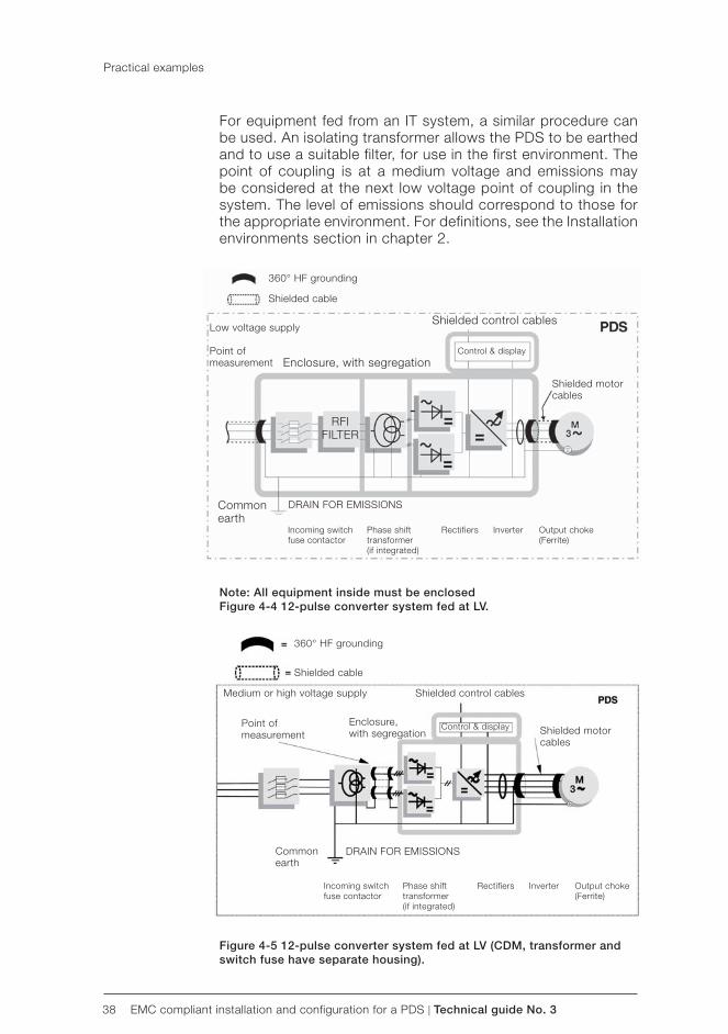
38 EMC compliant installation and configuration for a PDS | Technical guide No. 3
360° HF grounding
Shielded cable
Shielded control cables
Control & displayEnclosure, with segregation
Low voltage supply
Point ofmeasurement
Shielded motorcables
RFIFILTER
Commonearth
DRAIN FOR EMISSIONS
Incoming switchfuse contactor
Phase shifttransformer(if integrated)
Rectifiers Inverter Output choke(Ferrite)
Commonearth
DRAIN FOR EMISSIONS
Incoming switchfuse contactor
Phase shifttransformer(if integrated)
Rectifiers Inverter Output choke(Ferrite)
360° HF grounding
Shielded cable
Shielded control cables
Control & display Shielded motorcables
Enclosure,with segregation
Point ofmeasurement
Medium or high voltage supply
For equipment fed from an IT system, a similar procedure can be used. An isolating transformer allows the PDS to be earthed and to use a suitable filter, for use in the first environment. The point of coupling is at a medium voltage and emissions may be considered at the next low voltage point of coupling in the system. The level of emissions should correspond to those for the appropriate environment. For definitions, see the Installation environments section in chapter 2.
Note: All equipment inside must be enclosedFigure 4-4 12-pulse converter system fed at LV.
Figure 4-5 12-pulse converter system fed at LV (CDM, transformer and switch fuse have separate housing).
Practical examples
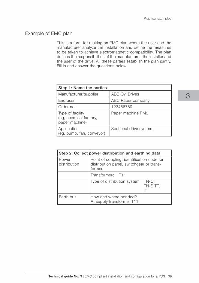
Technical guide No. 3 | EMC compliant installation and configuration for a PDS 39
3
Practical examples
Example of EMC plan
This is a form for making an EMC plan where the user and the manufacturer analyze the installation and define the measures to be taken to achieve electromagnetic compatibility. The plan defines the responsibilities of the manufacturer, the installer and the user of the drive. All these parties establish the plan jointly. Fill in and answer the questions below.
Step 1: Name the parties
Manufacturer/supplier ABB Oy, Drives
End user ABC Paper company
Order no. 123456789
Type of facility(eg, chemical factory, paper machine)
Paper machine PM3
Application(eg, pump. fan, conveyor)
Sectional drive system
Step 2: Collect power distribution and earthing data
Powerdistribution
Point of coupling: identification code for distribution panel, switchgear or trans-former
Transformerc T11
Type of distribution system TN-C,TN-S TT,IT
Earth bus How and where bonded?At supply transformer T11
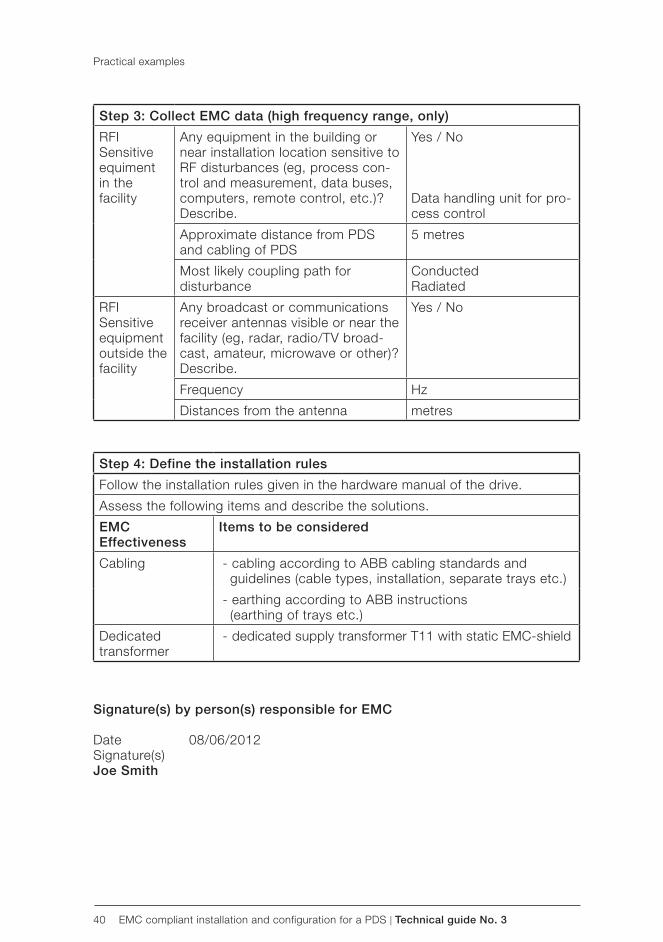
40 EMC compliant installation and configuration for a PDS | Technical guide No. 3
Signature(s) by person(s) responsible for EMC
Date 08/06/2012Signature(s)Joe Smith
Practical examples
Step 3: Collect EMC data (high frequency range, only)
RFI Sensitive equiment in the facility
Any equipment in the building or near installation location sensitive to RF disturbances (eg, process con-trol and measurement, data buses, computers, remote control, etc.)? Describe.
Yes / No
Data handling unit for pro-cess control
Approximate distance from PDS and cabling of PDS
5 metres
Most likely coupling path for disturbance
Conducted Radiated
RFI Sensitive equipment outside the facility
Any broadcast or communications receiver antennas visible or near the facility (eg, radar, radio/TV broad-cast, amateur, microwave or other)? Describe.
Yes / No
Frequency Hz
Distances from the antenna metres
Step 4: Define the installation rules
Follow the installation rules given in the hardware manual of the drive.
Assess the following items and describe the solutions.
EMCEffectiveness
Items to be considered
Cabling - cabling according to ABB cabling standards andguidelines (cable types, installation, separate trays etc.)
- earthing according to ABB instructions(earthing of trays etc.)
Dedicatedtransformer
- dedicated supply transformer T11 with static EMC-shield
Technical guide No. 3 | EMC compliant installation and configuration for a PDS 41
3
Chapter 5 - Bibliography
Various texts are referred to in this guide. They are recommended further reading to assist in achieving compliant installations:
EN 61800-3, Adjustable speed electrical power drive systems - part 3, EMC product standard including specific test (published by CENELEC, Brussels, Belgium and National Standards organi-zations in EU member countries).
EN 61800-3:2004
Interference Free Electronics by Dr. Sten Benda (published by ABB Industry Ab, Västerås, Sweden)
Technical guide No. 2 - EU Council Directives and adjustable speed electrical power drive systems, code 3AFE61253980 (published by ABB Oy Drives, Helsinki, Finland)
Grounding and cabling of the drive system, code 3AFY61201998 (published by ABB Oy Drives, Helsinki, Finland)
42 EMC compliant installation and configuration for a PDS | Technical guide No. 3
Chapter 6 - Index
Symbols12-pulse rectifier 37
Aantenna 30apparatus 7, 12, 13, 14appliance 12, 13, 14assembler 7, 12, 13, 14, 16, 17, 21
Bbasic drive module 8, 11
Ccabinet 13, 20, 21, 27, 35cable gland 25, 27CE mark 7, 12, 14, 15CENELEC 41complete drive module 8, 11components 12conducted radio frequency distur-bance 10conduction 10control electronics 10converter 23, 28, 29, 35, 36, 38cross coupling 36customer 8
Ddelta winding 37DOL 36double shielded cable 31drive 7, 8, 9, 11, 12, 13, 14, 19, 20, 21, 22, 25, 29, 31, 32, 37, 39, 40
EEEA 7, 10electrical surge 10Electromagnetic compatibility 10electromagnetic disturbance 14electromagnetic environment 10electrostatic discharge 10enclosure 12, 17, 18, 19, 20, 23, 24, 26, 28, 38end user 12, 13, 16, 39environment 10, 15, 16, 37equipment 7, 8, 10, 11, 12, 14, 19, 24, 38, 40
FFaraday cage 20, 21, 22, 23, 26, 27, 28, 29, 31, 32fast transient burst 10ferrite core 33ferrite ring 33, 34finished appliance 12, 13, 14first environment 15, 16, 37fixed installation 12, 14, 15, 17frequency converter 31, 35fuse 38
Ggasket 22, 23, 25gland plate 25, 26, 27
Hharmonics 10high-frequency emission 10high-frequency phenomena 10
Iimbalance 10isolating transformer 38IT system 37, 38
Llow-frequency phenomena 10low-voltage network 15Low Voltage Directive 7
MMachinery Directive 7manufacturer 7, 8, 12, 13, 14, 16,17, 21, 23, 24, 27medium voltage network 15motor 19, 22, 25, 27, 31
Nnotches 10
Ooriginal equipment manufacturers 7
Pphase shift transformer 37pigtail 25, 27, 28plastic trunking 30point of coupling 38power components 10power distribution networks 15power drive system 1, 3, 10, 11power supply network 15, 16
Rradiated electromagnetic field 10radiation 10RFI filter 20, 23, 35, 37
Ssecond environment 16, 17single functional unit 8, 14strain relief clamp 27sub-assembly 12system 7, 8, 9, 10, 11, 12, 13, 14, 16, 17, 19, 20, 31, 33, 36, 37, 38, 39, 41
Ttechnical documentation 7, 8, 12, 13transformer 15, 37, 38twisted pair 24, 30, 31
Uunrestricted 15user 7, 8, 11, 12, 15, 16

Technical guide No. 3 | EMC compliant installation and configuration for a PDS 43
3AFE
6134
8280
RE
V D
EN
8.6
.201
2 #1
6342
Contact us
For more information please contact your local ABB representative or visit:
www.abb.com/driveswww.abb.com/drivespartners
© Copyright 2012 ABB. All rights reserved. Specifications subject to change without notice.

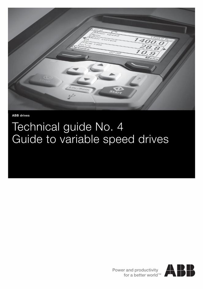
Technical guide No. 4Guide to variable speed drives
ABB drives

2 Guide to variable speed drives | Technical guide No. 4

Technical guide No. 4 | Guide to variable speed drives 3
© Copyright 2011 ABB. All rights reserved.
Specifications subject to change without notice.
3AFE61389211 REV C 12.5.2011
Technical guide No. 4Guide to variable speed drives
4

4 Guide to variable speed drives | Technical guide No. 4
Technical guide No. 4 | Guide to variable speed drives 5
4
Contents
Chapter 1 - Introduction ............................................................................7
General ..............................................................................................7
Chapter 2 - Processes and their requirements ..........................................8
Why variable speed control? ...............................................................8Industrial segments with VSD processes..............................................9Variables in processing systems ........................................................10Machines are used to alter materials’ properties... .............................11
Well defined shape .......................................................................11Indefinite shape ...........................................................................11
...and to transport materials ..............................................................12Solid materials .............................................................................12Liquid materials ...........................................................................12Gaseous materials .......................................................................12
Chapter 3 - The workhorse of industry: the electric motor ......................13
Electric motors drive most machines .................................................13Motors convert electrical energy into mechanical energy ....................14Frequency converters control electromagnetic induction .....................15The efficiency of the drive system ......................................................16Reversed rotation or torque is sometimes required .............................17The load, friction and inertia resist rotation .........................................18The motor has to overcome the loading torque ..................................19The drive torque and load torque are equal at nominal speed .............20
Chapter 4 - Variable volumes require some form of control ....................21
Variable material flow and input/output requirements ..........................21Simpler control methods ...................................................................22The best control method is VSD ........................................................23Mechanical, hydraulic and electrical VSDs .........................................24
Hydraulic coupling .......................................................................24DC drive ......................................................................................24AC drive ......................................................................................24
Electrical VSDs dominate the market .................................................25Maintenance costs .......................................................................25Productivity .................................................................................25Energy saving ..............................................................................25Higher quality ..............................................................................25
The AC drives market is growing fast .................................................26
Chapter 5 - AC drive: the leading control method ...................................27
The basic functions of an AC drive ....................................................27A motor’s load capacity curves with an AC drive ................................28
6 Guide to variable speed drives | Technical guide No. 4
AC drive features for better process control .......................................29Reversing ....................................................................................30Torque control .............................................................................30Eliminating mechanical vibrations ..................................................30Power loss ride-through ...............................................................31Stall function ...............................................................................31Slip compensation .......................................................................32Flying start ..................................................................................32Environmental features .................................................................33EMC............................................................................................33
Chapter 6 - Cost benefits of AC drives ....................................................34
Technical differences between other systems and AC drives ...............35No mechanical control parts needed .................................................36Factors affecting cost .......................................................................37Investment costs: mechanical and electrical components ...................38
The motor ...................................................................................38The AC drive................................................................................38
Installation costs: throttling compared to AC drive ..............................39Operational costs: maintenance and drive energy ..............................40Total cost comparison ......................................................................41
Chapter 7 - Index .....................................................................................42

Technical guide No. 4 | Guide to variable speed drives 7
4
Chapter 1 - Introduction
General
This guide continues ABB’s technical guide series, describing different variable speed drives (VSD) and how they are used in industrial processes. Special attention has been given to electri-cal VSDs and especially to AC Drives.
The guide tries to be as practical as possible. No special know-ledge of VSDs is required, although basic technical know-how is required to fully understand the terms and descriptions used.
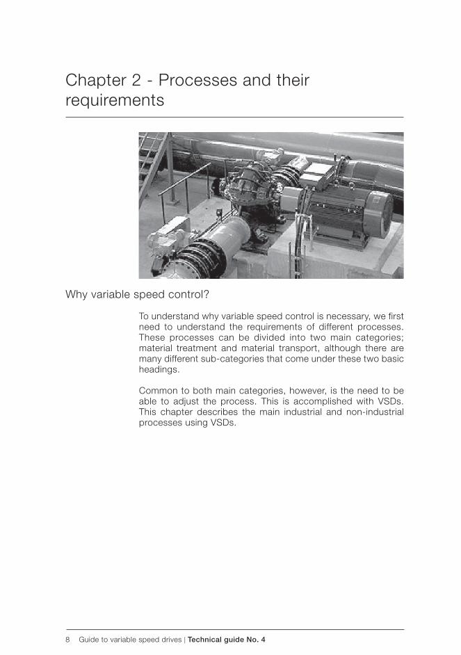
8 Guide to variable speed drives | Technical guide No. 4
Chapter 2 - Processes and their requirements
Why variable speed control?
To understand why variable speed control is necessary, we first need to understand the requirements of different processes. These processes can be divided into two main categories; material treatment and material transport, although there are many different sub-categories that come under these two basic headings.
Common to both main categories, however, is the need to be able to adjust the process. This is accomplished with VSDs. This chapter describes the main industrial and non-industrial processes using VSDs.
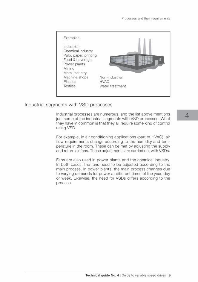
Technical guide No. 4 | Guide to variable speed drives 9
Examples
Industrial:Chemical industryPulp, paper, printingFood & beveragePower plantsMiningMetal industryMachine shopsPlasticsTextiles
Non-industrial:HVACWater treatment
4
Industrial segments with VSD processes
Industrial processes are numerous, and the list above mentions just some of the industrial segments with VSD processes. What they have in common is that they all require some kind of control using VSD.
For example, in air conditioning applications (part of HVAC), air flow requirements change according to the humidity and tem-perature in the room. These can be met by adjusting the supply and return air fans. These adjustments are carried out with VSDs.
Fans are also used in power plants and the chemical industry. In both cases, the fans need to be adjusted according to the main process. In power plants, the main process changes due to varying demands for power at different times of the year, day or week. Likewise, the need for VSDs differs according to the process.
Processes and their requirements
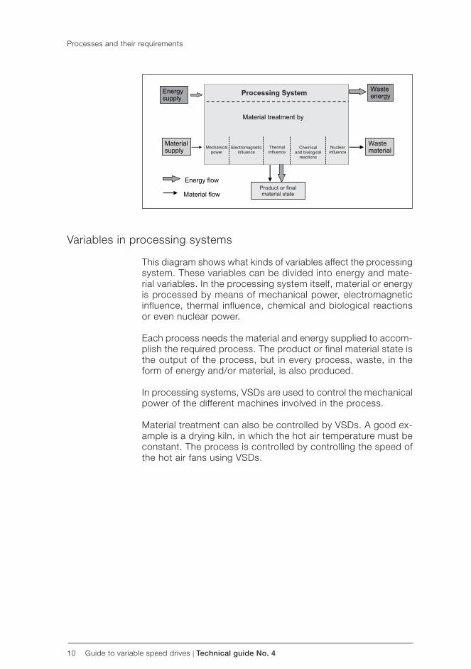
10 Guide to variable speed drives | Technical guide No. 4
Processes and their requirements
Variables in processing systems
This diagram shows what kinds of variables affect the processing system. These variables can be divided into energy and mate-rial variables. In the processing system itself, material or energy is processed by means of mechanical power, electromagnetic influence, thermal influence, chemical and biological reactions or even nuclear power.
Each process needs the material and energy supplied to accom-plish the required process. The product or final material state is the output of the process, but in every process, waste, in the form of energy and/or material, is also produced.
In processing systems, VSDs are used to control the mechanical power of the different machines involved in the process.
Material treatment can also be controlled by VSDs. A good ex-ample is a drying kiln, in which the hot air temperature must be constant. The process is controlled by controlling the speed of the hot air fans using VSDs.
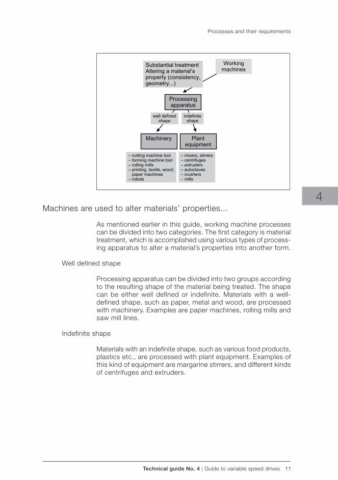
Technical guide No. 4 | Guide to variable speed drives 11
4
Processes and their requirements
Machines are used to alter materials’ properties...
As mentioned earlier in this guide, working machine processes can be divided into two categories. The first category is material treatment, which is accomplished using various types of process-ing apparatus to alter a material’s properties into another form.
Well defined shape
Processing apparatus can be divided into two groups according to the resulting shape of the material being treated. The shape can be either well defined or indefinite. Materials with a well-defined shape, such as paper, metal and wood, are processed with machinery. Examples are paper machines, rolling mills and saw mill lines.
Indefinite shape
Materials with an indefinite shape, such as various food products, plastics etc., are processed with plant equipment. Examples of this kind of equipment are margarine stirrers, and different kinds of centrifuges and extruders.
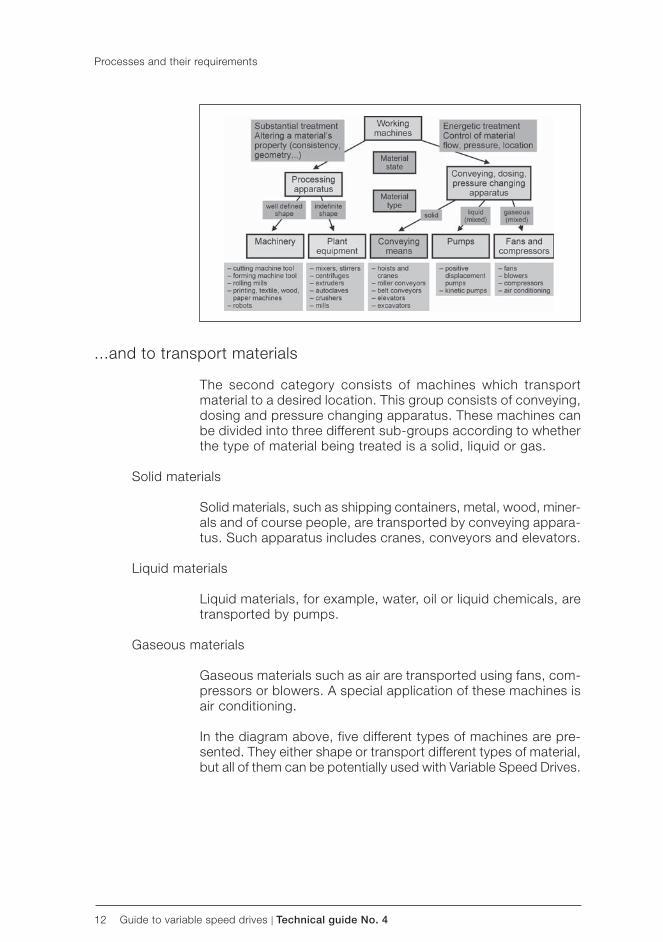
12 Guide to variable speed drives | Technical guide No. 4
Processes and their requirements
...and to transport materials
The second category consists of machines which transport material to a desired location. This group consists of conveying, dosing and pressure changing apparatus. These machines can be divided into three different sub-groups according to whether the type of material being treated is a solid, liquid or gas.
Solid materials
Solid materials, such as shipping containers, metal, wood, miner-als and of course people, are transported by conveying appara-tus. Such apparatus includes cranes, conveyors and elevators.
Liquid materials
Liquid materials, for example, water, oil or liquid chemicals, are transported by pumps.
Gaseous materials
Gaseous materials such as air are transported using fans, com-pressors or blowers. A special application of these machines is air conditioning.
In the diagram above, five different types of machines are pre-sented. They either shape or transport different types of material, but all of them can be potentially used with Variable Speed Drives.
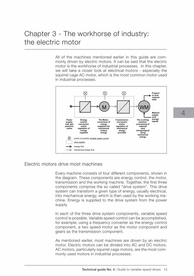
Technical guide No. 4 | Guide to variable speed drives 13
4
Chapter 3 - The workhorse of industry: the electric motor
All of the machines mentioned earlier in this guide are com-monly driven by electric motors. It can be said that the electric motor is the workhorse of industrial processes. In this chapter, we will take a closer look at electrical motors - especially the squirrel cage AC motor, which is the most common motor used in industrial processes.
Electric motors drive most machines
Every machine consists of four different components, shown in the diagram. These components are energy control, the motor, transmission and the working machine. Together, the first three components comprise the so called “drive system”. This drive system can transform a given type of energy, usually electrical, into mechanical energy, which is then used by the working ma-chine. Energy is supplied to the drive system from the power supply.
In each of the three drive system components, variable speed control is possible. Variable speed control can be accomplished, for example, using a frequency converter as the energy control component, a two speed motor as the motor component and gears as the transmission component.
As mentioned earlier, most machines are driven by an electric motor. Electric motors can be divided into AC and DC motors. AC motors, particularly squirrel cage motors, are the most com-monly used motors in industrial processes.
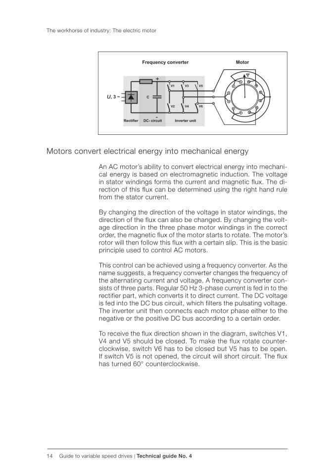
14 Guide to variable speed drives | Technical guide No. 4
U
The workhorse of industry: The electric motor
Motors convert electrical energy into mechanical energy
An AC motor’s ability to convert electrical energy into mechani-cal energy is based on electromagnetic induction. The voltage in stator windings forms the current and magnetic flux. The di-rection of this flux can be determined using the right hand rule from the stator current.
By changing the direction of the voltage in stator windings, the direction of the flux can also be changed. By changing the volt-age direction in the three phase motor windings in the correct order, the magnetic flux of the motor starts to rotate. The motor’s rotor will then follow this flux with a certain slip. This is the basic principle used to control AC motors.
This control can be achieved using a frequency converter. As the name suggests, a frequency converter changes the frequency of the alternating current and voltage. A frequency converter con-sists of three parts. Regular 50 Hz 3-phase current is fed in to the rectifier part, which converts it to direct current. The DC voltage is fed into the DC bus circuit, which filters the pulsating voltage. The inverter unit then connects each motor phase either to the negative or the positive DC bus according to a certain order.
To receive the flux direction shown in the diagram, switches V1, V4 and V5 should be closed. To make the flux rotate counter-clockwise, switch V6 has to be closed but V5 has to be open. If switch V5 is not opened, the circuit will short circuit. The flux has turned 60° counterclockwise.
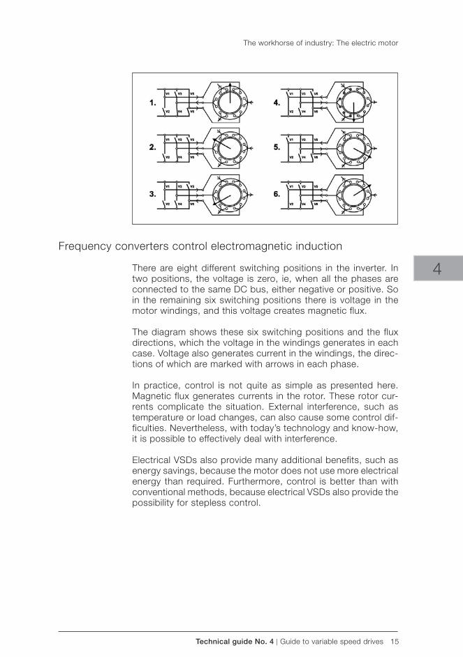
Technical guide No. 4 | Guide to variable speed drives 15
4
The workhorse of industry: The electric motor
Frequency converters control electromagnetic induction
There are eight different switching positions in the inverter. In two positions, the voltage is zero, ie, when all the phases are connected to the same DC bus, either negative or positive. So in the remaining six switching positions there is voltage in the motor windings, and this voltage creates magnetic flux.
The diagram shows these six switching positions and the flux directions, which the voltage in the windings generates in each case. Voltage also generates current in the windings, the direc-tions of which are marked with arrows in each phase.
In practice, control is not quite as simple as presented here. Magnetic flux generates currents in the rotor. These rotor cur-rents complicate the situation. External interference, such as temperature or load changes, can also cause some control dif-ficulties. Nevertheless, with today’s technology and know-how, it is possible to effectively deal with interference.
Electrical VSDs also provide many additional benefits, such as energy savings, because the motor does not use more electrical energy than required. Furthermore, control is better than with conventional methods, because electrical VSDs also provide the possibility for stepless control.
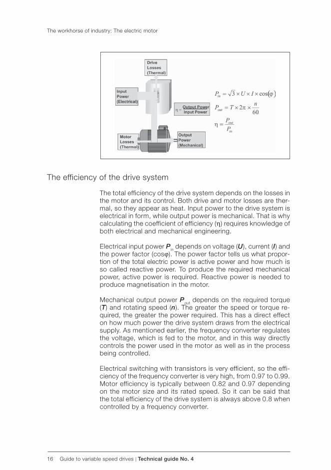
16 Guide to variable speed drives | Technical guide No. 4
The workhorse of industry: The electric motor
The efficiency of the drive system
The total efficiency of the drive system depends on the losses in the motor and its control. Both drive and motor losses are ther-mal, so they appear as heat. Input power to the drive system is electrical in form, while output power is mechanical. That is why calculating the coefficient of efficiency (η) requires knowledge of both electrical and mechanical engineering.
Electrical input power Pin depends on voltage (U), current (I) and the power factor (cosϕ). The power factor tells us what propor-tion of the total electric power is active power and how much is so called reactive power. To produce the required mechanical power, active power is required. Reactive power is needed to produce magnetisation in the motor.
Mechanical output power Pout depends on the required torque (T) and rotating speed (n). The greater the speed or torque re-quired, the greater the power required. This has a direct effect on how much power the drive system draws from the electrical supply. As mentioned earlier, the frequency converter regulates the voltage, which is fed to the motor, and in this way directly controls the power used in the motor as well as in the process being controlled.
Electrical switching with transistors is very efficient, so the effi-ciency of the frequency converter is very high, from 0.97 to 0.99. Motor efficiency is typically between 0.82 and 0.97 depending on the motor size and its rated speed. So it can be said that the total efficiency of the drive system is always above 0.8 when controlled by a frequency converter.
Technical guide No. 4 | Guide to variable speed drives 17
4
The workhorse of industry: The electric motor
Reversed rotation or torque is sometimes required
In some cases, reversed rotation of the motor is required. In addition, torque direction requirements might change. These factors combined form the so called “ four quadrant drive”. The name comes from the four different quadrants (I to IV) shown in the diagram.
I quadrant: In the first quadrant, the motor is rotating clockwise. Because the torque is in the same direction as the speed, the drive is accelerating.
II quadrant: In the second quadrant, the motor is still rotating clockwise, but the torque is in the opposite direction, so the drive is decelerating.
III & IV quadrants: In the third and fourth quadrant, the motor is rotating counterclockwise and the drive is again accelerating or decelerating, depending on the torque direction.
With a frequency converter, torque direction changes can be im-plemented independent of the direction of rotation. To produce an efficient four quadrant drive, some kind of braking arrangement is required. This kind of torque control is especially required in crane applications, where the rotation direction might change, but the torque direction remains the same.
18 Guide to variable speed drives | Technical guide No. 4
The workhorse of industry: The electric motor
The load, friction and inertia resist rotation
The motor must produce the required torque to overcome the load torque. Load torque consists of friction, inertia of the moving parts and the load itself, which depends on the application. In the example in the diagram, the motor torque has to be greater than the load torque, which is dependent on the mass of the box, if the box is to rise.
Load factors change according to the application. For example, in a crusher, the load torque is dependent not only on friction and inertia, but also on the hardness of the crushed material. In fans and blowers, air pressure changes affect the load torque, and so on.
Technical guide No. 4 | Guide to variable speed drives 19
4
The workhorse of industry: The electric motor
The motor has to overcome the loading torque
In any case, the loading torque has to be known before select-ing the motor for the application. The required speed also has to be known. Only then can a suitable motor be selected for the application.
If the motor is too small, the requirements cannot be met and this might lead to serious problems. For example, in crane ap-plications, a motor that is too small may not be able to lift the required load quickly enough to the desired height. It might even drop the load completely, as shown in the diagram. This could be disastrous for people working at the harbour or site where this crane would be used. To calculate the rated torque of the motor the following formula can be used:
T[Nm]=9550 x P[kW]
n[1/min]
20 Guide to variable speed drives | Technical guide No. 4
The workhorse of industry: The electric motor
The drive torque and load torque are equal at nominal speed
A motor’s torque/speed curve is unique and has to be calculated for every motor type separately. A typical torque/speed curve is shown in the graph as Tm. As can be seen, the maximum load torque is reached just below nominal speed.
Load torque Tl usually increases with speed. Depending on the application it can be linear or quadratic. The motor will auto-matically accelerate until the load torque and motor torque are equal. This point is shown on the graph as the intersection of Tm and Tl. Actual torque (Tact) is shown on the y-axis and actual speed (nact) on the x-axis.
These are the principles that govern how an ordinary squirrel cage motor works. With a frequency converter, optimal control performance can be obtained from the motor and the whole drive system. This will be introduced later in this guide.
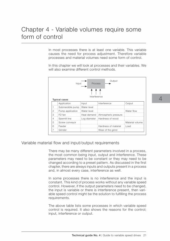
Technical guide No. 4 | Guide to variable speed drives 21
Typical cases
Application Input Interference Output
1 Submersible pump Water level
2 Pump application Water level Water flow
3 FD fan Heat demand Atmospheric pressure
4 Sawmill line Log diameter Hardness of wood
5 Screw conveyor Material volume
6 Feeder Hardness of material Load
7 Grinder Wear of the grind
ProcessInputOutput
Interference 4
Chapter 4 - Variable volumes require some form of control
In most processes there is at least one variable. This variable causes the need for process adjustment. Therefore variable processes and material volumes need some form of control.
In this chapter we will look at processes and their variables. We will also examine different control methods.
Variable material flow and input/output requirements
There may be many different parameters involved in a process, the most common being input, output and interference. These parameters may need to be constant or they may need to be changed according to a preset pattern. As discussed in the first chapter, there are always inputs and outputs present in a process and, in almost every case, interference as well.
In some processes there is no interference and the input is constant. This kind of process works without any variable speed control. However, if the output parameters need to be changed, the input is variable or there is interference present, then vari-able speed control might be the solution to fulfilling the process requirements.
The above table lists some processes in which variable speed control is required. It also shows the reasons for the control; input, interference or output.
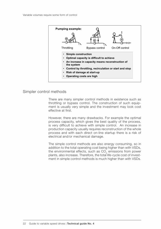
22 Guide to variable speed drives | Technical guide No. 4
Variable volumes require some form of control
Simpler control methods
There are many simpler control methods in existence such as throttling or bypass control. The construction of such equip-ment is usually very simple and the investment may look cost effective at first.
However, there are many drawbacks. For example the optimal process capacity, which gives the best quality of the process, is very difficult to achieve with simple control. An increase in production capacity usually requires reconstruction of the whole process and with each direct on-line startup there is a risk of electrical and/or mechanical damage.
The simple control methods are also energy consuming, so in addition to the total operating cost being higher than with VSDs, the environmental effects, such as CO2 emissions from power plants, also increase. Therefore, the total life-cycle cost of invest-ment in simple control methods is much higher than with VSDs.
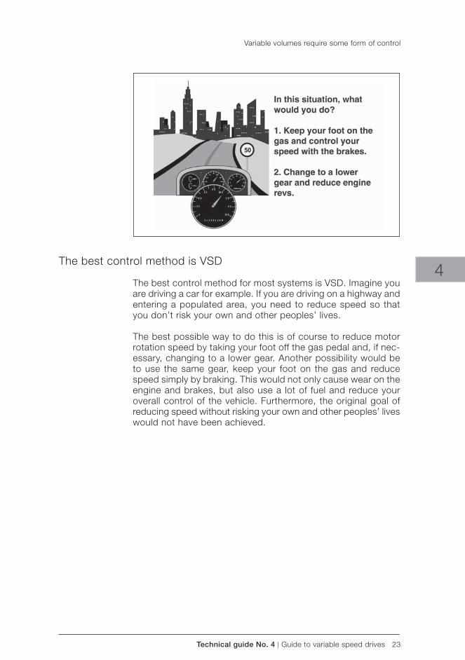
Technical guide No. 4 | Guide to variable speed drives 23
4
Variable volumes require some form of control
The best control method is VSD
The best control method for most systems is VSD. Imagine you are driving a car for example. If you are driving on a highway and entering a populated area, you need to reduce speed so that you don’t risk your own and other peoples’ lives.
The best possible way to do this is of course to reduce motor rotation speed by taking your foot off the gas pedal and, if nec-essary, changing to a lower gear. Another possibility would be to use the same gear, keep your foot on the gas and reduce speed simply by braking. This would not only cause wear on the engine and brakes, but also use a lot of fuel and reduce your overall control of the vehicle. Furthermore, the original goal of reducing speed without risking your own and other peoples’ lives would not have been achieved.
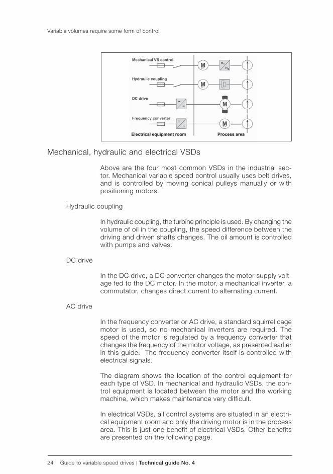
24 Guide to variable speed drives | Technical guide No. 4
Variable volumes require some form of control
Mechanical, hydraulic and electrical VSDs
Above are the four most common VSDs in the industrial sec-tor. Mechanical variable speed control usually uses belt drives, and is controlled by moving conical pulleys manually or with positioning motors.
Hydraulic coupling
In hydraulic coupling, the turbine principle is used. By changing the volume of oil in the coupling, the speed difference between the driving and driven shafts changes. The oil amount is controlled with pumps and valves.
DC drive
In the DC drive, a DC converter changes the motor supply volt-age fed to the DC motor. In the motor, a mechanical inverter, a commutator, changes direct current to alternating current.
AC drive
In the frequency converter or AC drive, a standard squirrel cage motor is used, so no mechanical inverters are required. The speed of the motor is regulated by a frequency converter that changes the frequency of the motor voltage, as presented earlier in this guide. The frequency converter itself is controlled with electrical signals.
The diagram shows the location of the control equipment for each type of VSD. In mechanical and hydraulic VSDs, the con-trol equipment is located between the motor and the working machine, which makes maintenance very difficult.
In electrical VSDs, all control systems are situated in an electri-cal equipment room and only the driving motor is in the process area. This is just one benefit of electrical VSDs. Other benefits are presented on the following page.
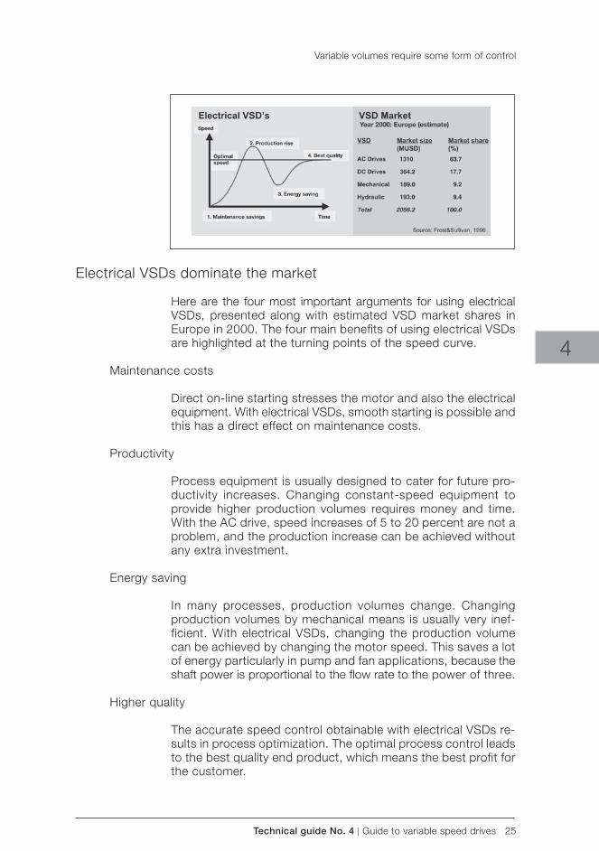
Technical guide No. 4 | Guide to variable speed drives 25
4
Variable volumes require some form of control
Electrical VSDs dominate the market
Here are the four most important arguments for using electrical VSDs, presented along with estimated VSD market shares in Europe in 2000. The four main benefits of using electrical VSDs are highlighted at the turning points of the speed curve.
Maintenance costs
Direct on-line starting stresses the motor and also the electrical equipment. With electrical VSDs, smooth starting is possible and this has a direct effect on maintenance costs.
Productivity
Process equipment is usually designed to cater for future pro-ductivity increases. Changing constant-speed equipment to provide higher production volumes requires money and time. With the AC drive, speed increases of 5 to 20 percent are not a problem, and the production increase can be achieved without any extra investment.
Energy saving
In many processes, production volumes change. Changing production volumes by mechanical means is usually very inef-ficient. With electrical VSDs, changing the production volume can be achieved by changing the motor speed. This saves a lot of energy particularly in pump and fan applications, because the shaft power is proportional to the flow rate to the power of three.
Higher quality
The accurate speed control obtainable with electrical VSDs re-sults in process optimization. The optimal process control leads to the best quality end product, which means the best profit for the customer.
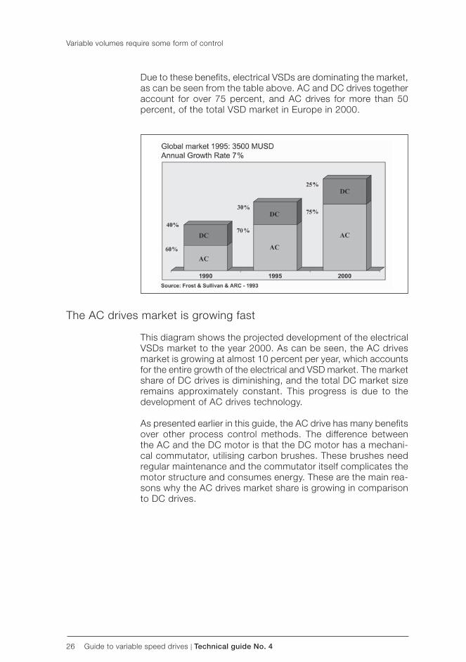
26 Guide to variable speed drives | Technical guide No. 4
Due to these benefits, electrical VSDs are dominating the market, as can be seen from the table above. AC and DC drives together account for over 75 percent, and AC drives for more than 50 percent, of the total VSD market in Europe in 2000.
Variable volumes require some form of control
The AC drives market is growing fast
This diagram shows the projected development of the electrical VSDs market to the year 2000. As can be seen, the AC drives market is growing at almost 10 percent per year, which accounts for the entire growth of the electrical and VSD market. The market share of DC drives is diminishing, and the total DC market size remains approximately constant. This progress is due to the development of AC drives technology.
As presented earlier in this guide, the AC drive has many benefits over other process control methods. The difference between the AC and the DC motor is that the DC motor has a mechani-cal commutator, utilising carbon brushes. These brushes need regular maintenance and the commutator itself complicates the motor structure and consumes energy. These are the main rea-sons why the AC drives market share is growing in comparison to DC drives.
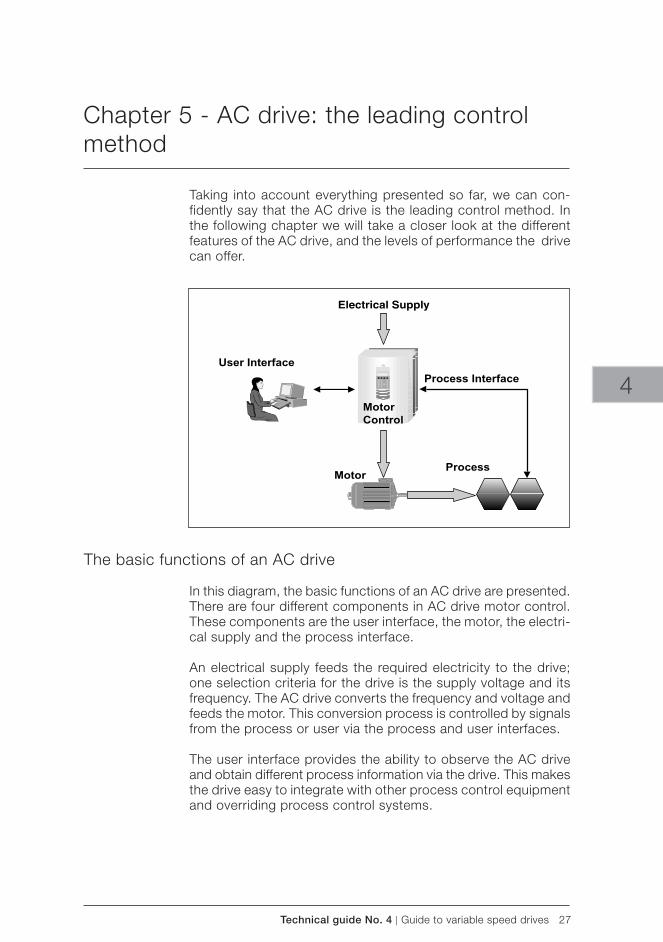
Technical guide No. 4 | Guide to variable speed drives 27
4
Chapter 5 - AC drive: the leading control method
Taking into account everything presented so far, we can con-fidently say that the AC drive is the leading control method. In the following chapter we will take a closer look at the different features of the AC drive, and the levels of performance the drive can offer.
The basic functions of an AC drive
In this diagram, the basic functions of an AC drive are presented. There are four different components in AC drive motor control. These components are the user interface, the motor, the electri-cal supply and the process interface.
An electrical supply feeds the required electricity to the drive; one selection criteria for the drive is the supply voltage and its frequency. The AC drive converts the frequency and voltage and feeds the motor. This conversion process is controlled by signals from the process or user via the process and user interfaces.
The user interface provides the ability to observe the AC drive and obtain different process information via the drive. This makes the drive easy to integrate with other process control equipment and overriding process control systems.
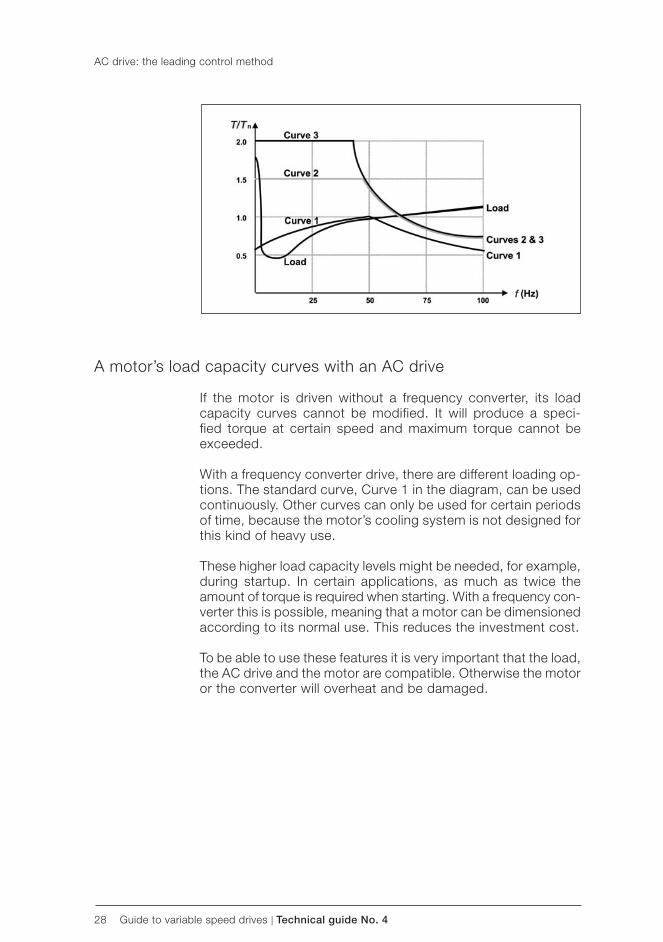
28 Guide to variable speed drives | Technical guide No. 4
AC drive: the leading control method
A motor’s load capacity curves with an AC drive
If the motor is driven without a frequency converter, its load capacity curves cannot be modified. It will produce a speci-fied torque at certain speed and maximum torque cannot be exceeded.
With a frequency converter drive, there are different loading op-tions. The standard curve, Curve 1 in the diagram, can be used continuously. Other curves can only be used for certain periods of time, because the motor’s cooling system is not designed for this kind of heavy use.
These higher load capacity levels might be needed, for example, during startup. In certain applications, as much as twice the amount of torque is required when starting. With a frequency con-verter this is possible, meaning that a motor can be dimensioned according to its normal use. This reduces the investment cost.
To be able to use these features it is very important that the load, the AC drive and the motor are compatible. Otherwise the motor or the converter will overheat and be damaged.
Technical guide No. 4 | Guide to variable speed drives 29
Important features:- inputs and outputs- reversing function- ramp times acceleration/deceleration- variable torque V/Hz settings- torque boosting- eliminating mechanical vibrations- load limits to prevent nuisance faults- power loss ride-through- stall function- slip compensation- flying start
4
AC drive: the leading control method
AC drive features for better process control
AC drives also have other internal features and functions which are sometimes required for better process control. Examples of these features are listed in the diagram. With inputs and outputs for example, different kinds of process information can be fed to the drive and it will control the motor accordingly. Alternatively, the load can be limited to prevent nuisance faults and to protect the working machine and the whole drive system.
In the following sections the listed features are presented in more detail.
30 Guide to variable speed drives | Technical guide No. 4
Reversing
Reversing the motor rotation is simple to accomplish with an AC drive. With ABB’s frequency converters it can be achieved simply by pressing one button. Furthermore, it is possible to set different acceleration and deceleration ramp times. The ramp form can also be modified according to the user’s wishes. In the diagram (above, left) an S-ramp has been presented. Another possibility could be a linear ramp.
Torque control
Torque control is relatively simple with an AC drive. Torque boosting, which was presented earlier, is necessary if a very high starting torque is required. Variable torque U/f settings mean that maximum torque can be achieved at a lower speed of rotation than normal.
Eliminating mechanical vibrations
Mechanical vibrations can be eliminated by by-passing critical speeds. This means that when a motor is accelerated close to its critical speed, the drive will not allow the actual speed of the motor to follow the reference speed. When the critical point has been passed, the motor will return to the regular curve very quickly and pass the critical speed.
AC drive: the leading control method
Technical guide No. 4 | Guide to variable speed drives 31
4
Power loss ride-through
The power loss ride-through function is used if the incoming supply voltage is cut off. In such a situation, the AC drive will continue to operate using the kinetic energy of the rotating motor. The drive will be fully operational as long as the motor rotates and generates energy for the drive.
Stall function
With an AC drive, the motor can be protected in a stall situation with the stall function. It is possible to adjust supervision limits and choose how the drive reacts to the motor stall condition. Pro-tection is activated if three conditions are met at the same time.
1. The drive frequency has to be below the preset stall frequency.
2. The motor torque has to rise to a certain limit, calculated by the drive software.
3. The final condition is that the motor has been in the stall limit for longer than the time period set by the user.
AC drive: the leading control method
32 Guide to variable speed drives | Technical guide No. 4
Slip compensation
If the motor load torque is increased, the speed of the motor will decrease as shown in the diagram (above, left). To compensate for this slip, the torque/speed curve can be modified with the frequency converter so that torque increase can be accomplished with the same speed as previously.
Flying start
The flying start feature is used when a motor is connected to a flywheel or a high inertia load. The flying start works even without a speed feedback. In case of rotating motor, the inverter is first started with a reduced voltage and then synchronised to the rotating rotor. After synchronised the voltage and the speed are increased to the corresponding levels.
AC drive: the leading control method
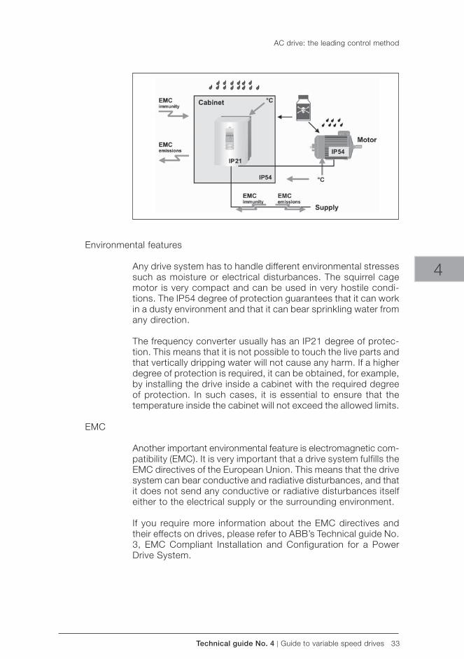
Technical guide No. 4 | Guide to variable speed drives 33
4
Environmental features
Any drive system has to handle different environmental stresses such as moisture or electrical disturbances. The squirrel cage motor is very compact and can be used in very hostile condi-tions. The IP54 degree of protection guarantees that it can work in a dusty environment and that it can bear sprinkling water from any direction.
The frequency converter usually has an IP21 degree of protec-tion. This means that it is not possible to touch the live parts and that vertically dripping water will not cause any harm. If a higher degree of protection is required, it can be obtained, for example, by installing the drive inside a cabinet with the required degree of protection. In such cases, it is essential to ensure that the temperature inside the cabinet will not exceed the allowed limits.
EMC
Another important environmental feature is electromagnetic com-patibility ( EMC). It is very important that a drive system fulfills the EMC directives of the European Union. This means that the drive system can bear conductive and radiative disturbances, and that it does not send any conductive or radiative disturbances itself either to the electrical supply or the surrounding environment.
If you require more information about the EMC directives and their effects on drives, please refer to ABB’s Technical guide No. 3, EMC Compliant Installation and Configuration for a Power Drive System.
AC drive: the leading control method
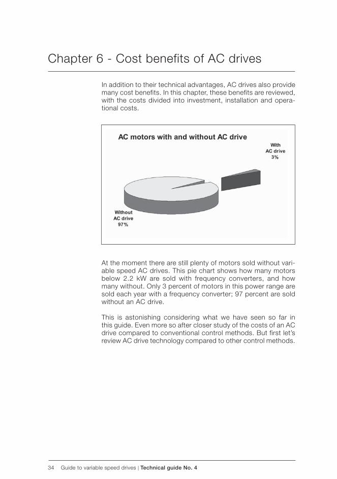
34 Guide to variable speed drives | Technical guide No. 4
Chapter 6 - Cost benefits of AC drives
In addition to their technical advantages, AC drives also provide many cost benefits. In this chapter, these benefits are reviewed, with the costs divided into investment, installation and opera-tional costs.
At the moment there are still plenty of motors sold without vari-able speed AC drives. This pie chart shows how many motors below 2.2 kW are sold with frequency converters, and how many without. Only 3 percent of motors in this power range are sold each year with a frequency converter; 97 percent are sold without an AC drive.
This is astonishing considering what we have seen so far in this guide. Even more so after closer study of the costs of an AC drive compared to conventional control methods. But first let’s review AC drive technology compared to other control methods.
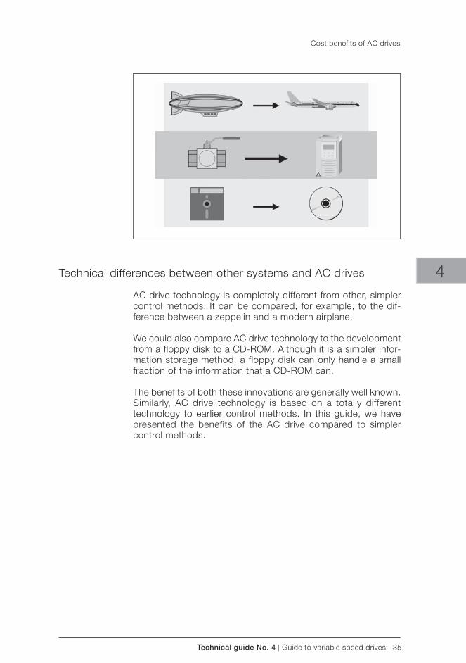
Technical guide No. 4 | Guide to variable speed drives 35
4Technical differences between other systems and AC drives
AC drive technology is completely different from other, simpler control methods. It can be compared, for example, to the dif-ference between a zeppelin and a modern airplane.
We could also compare AC drive technology to the development from a floppy disk to a CD-ROM. Although it is a simpler infor-mation storage method, a floppy disk can only handle a small fraction of the information that a CD-ROM can.
The benefits of both these innovations are generally well known. Similarly, AC drive technology is based on a totally different technology to earlier control methods. In this guide, we have presented the benefits of the AC drive compared to simpler control methods.
Cost benefits of AC drives
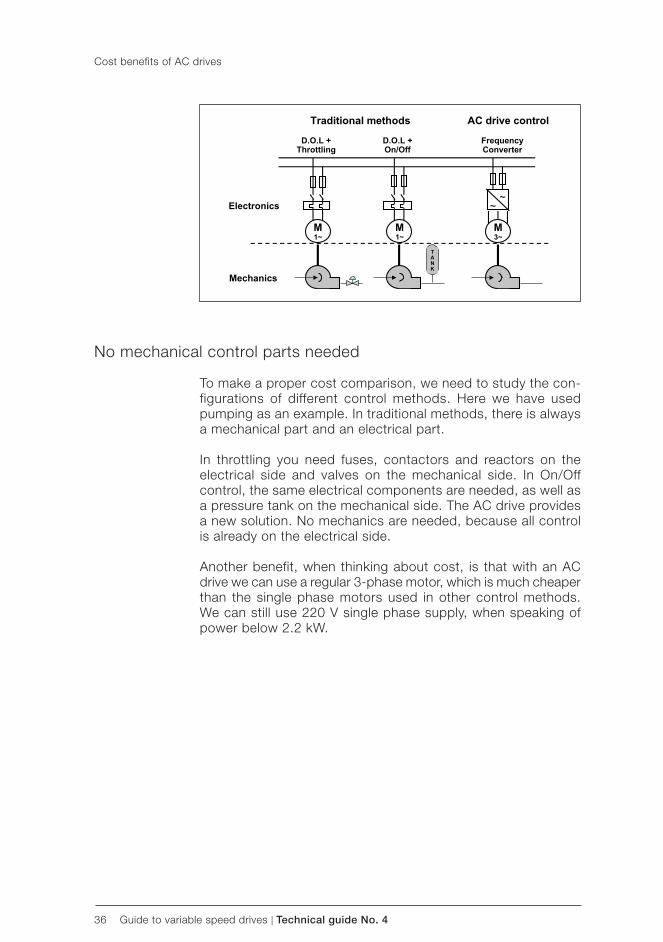
36 Guide to variable speed drives | Technical guide No. 4
Cost benefits of AC drives
No mechanical control parts needed
To make a proper cost comparison, we need to study the con-figurations of different control methods. Here we have used pumping as an example. In traditional methods, there is always a mechanical part and an electrical part.
In throttling you need fuses, contactors and reactors on the electrical side and valves on the mechanical side. In On/Off control, the same electrical components are needed, as well as a pressure tank on the mechanical side. The AC drive provides a new solution. No mechanics are needed, because all control is already on the electrical side.
Another benefit, when thinking about cost, is that with an AC drive we can use a regular 3-phase motor, which is much cheaper than the single phase motors used in other control methods. We can still use 220 V single phase supply, when speaking of power below 2.2 kW.

Technical guide No. 4 | Guide to variable speed drives 37
Conventional methods: AC drive:
both electrical and mechanical parts
all in one
many electrical parts only one electrical component
mechanical parts need regular maintenance
no mechanical parts, no wear and tear
mechanical control is energy consuming
saves energy
4
Cost benefits of AC drives
Factors affecting cost
This list compares the features of conventional control methods with those of the AC drive, as well as their effect on costs. In conventional methods there are both electrical and mechanical components, which usually have to be purchased separately. The costs are usually higher than if everything could be purchased at once.
Furthermore, mechanical parts wear out quickly. This directly affects maintenance costs and in the long run, maintenance is a very important cost item. In conventional methods there are also many electrical components. The installation cost is at least doubled when there are several different types of components rather than only one.
And last but not least, mechanical control is very energy consum-ing, while AC drives practically save energy. This not only helps reduce costs, but also helps minimise environmental impact by reducing emissions from power plants.
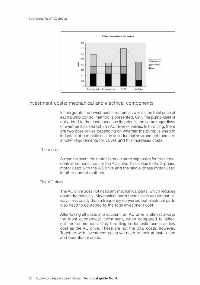
38 Guide to variable speed drives | Technical guide No. 4
Investment costs: mechanical and electrical components
In this graph, the investment structure as well as the total price of each pump control method is presented. Only the pump itself is not added to the costs because its price is the same regardless of whether it’s used with an AC drive or valves. In throttling, there are two possibilities depending on whether the pump is used in industrial or domestic use. In an industrial environment there are stricter requirements for valves and this increases costs.
The motor
As can be seen, the motor is much more expensive for traditional control methods than for the AC drive. This is due to the 3-phase motor used with the AC drive and the single phase motor used in other control methods.
The AC drive
The AC drive does not need any mechanical parts, which reduces costs dramatically. Mechanical parts themselves are almost al-ways less costly than a frequency converter, but electrical parts also need to be added to the total investment cost.
After taking all costs into account, an AC drive is almost always the most economical investment, when compared to differ-ent control methods. Only throttling in domestic use is as low cost as the AC drive. These are not the total costs, however. Together with investment costs we need to look at installation and operational costs.
Cost benefits of AC drives
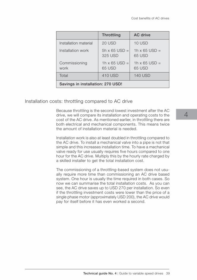
Technical guide No. 4 | Guide to variable speed drives 39
Throttling AC drive
Installation material 20 USD 10 USD
Installation work 5h x 65 USD = 1h x 65 USD = 325 USD 65 USD
Commissioning 1h x 65 USD = 1h x 65 USD =work 65 USD 65 USD
Total 410 USD 140 USD
Savings in installation: 270 USD!
4
Installation costs: throttling compared to AC drive
Because throttling is the second lowest investment after the AC drive, we will compare its installation and operating costs to the cost of the AC drive. As mentioned earlier, in throttling there are both electrical and mechanical components. This means twice the amount of installation material is needed.
Installation work is also at least doubled in throttling compared to the AC drive. To install a mechanical valve into a pipe is not that simple and this increases installation time. To have a mechanical valve ready for use usually requires five hours compared to one hour for the AC drive. Multiply this by the hourly rate charged by a skilled installer to get the total installation cost.
The commissioning of a throttling-based system does not usu-ally require more time than commissioning an AC drive based system. One hour is usually the time required in both cases. So now we can summarise the total installation costs. As you can see, the AC drive saves up to USD 270 per installation. So even if the throttling investment costs were lower than the price of a single phase motor (approximately USD 200), the AC drive would pay for itself before it has even worked a second.
Cost benefits of AC drives
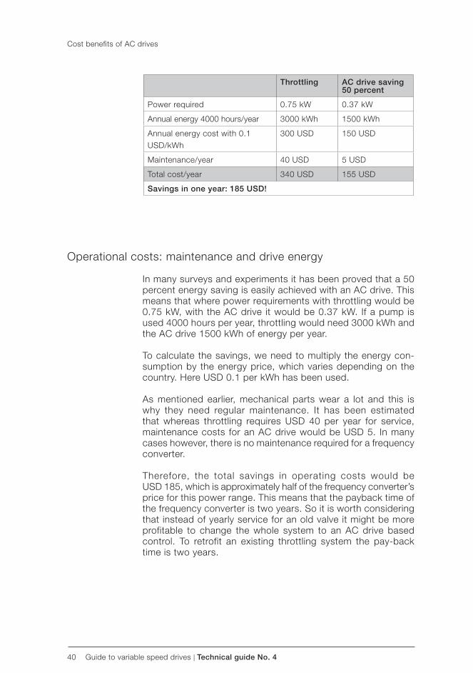
40 Guide to variable speed drives | Technical guide No. 4
Throttling AC drive saving 50 percent
Power required 0.75 kW 0.37 kW
Annual energy 4000 hours/year 3000 kWh 1500 kWh
Annual energy cost with 0.1USD/kWh
300 USD 150 USD
Maintenance/year 40 USD 5 USD
Total cost/year 340 USD 155 USD
Savings in one year: 185 USD!
Operational costs: maintenance and drive energy
In many surveys and experiments it has been proved that a 50 percent energy saving is easily achieved with an AC drive. This means that where power requirements with throttling would be 0.75 kW, with the AC drive it would be 0.37 kW. If a pump is used 4000 hours per year, throttling would need 3000 kWh and the AC drive 1500 kWh of energy per year.
To calculate the savings, we need to multiply the energy con-sumption by the energy price, which varies depending on the country. Here USD 0.1 per kWh has been used.
As mentioned earlier, mechanical parts wear a lot and this is why they need regular maintenance. It has been estimated that whereas throttling requires USD 40 per year for service, maintenance costs for an AC drive would be USD 5. In many cases however, there is no maintenance required for a frequency converter.
Therefore, the total savings in operating costs would beUSD 185, which is approximately half of the frequency converter’s price for this power range. This means that the payback time of the frequency converter is two years. So it is worth considering that instead of yearly service for an old valve it might be more profitable to change the whole system to an AC drive based control. To retrofit an existing throttling system the pay-back time is two years.
Cost benefits of AC drives
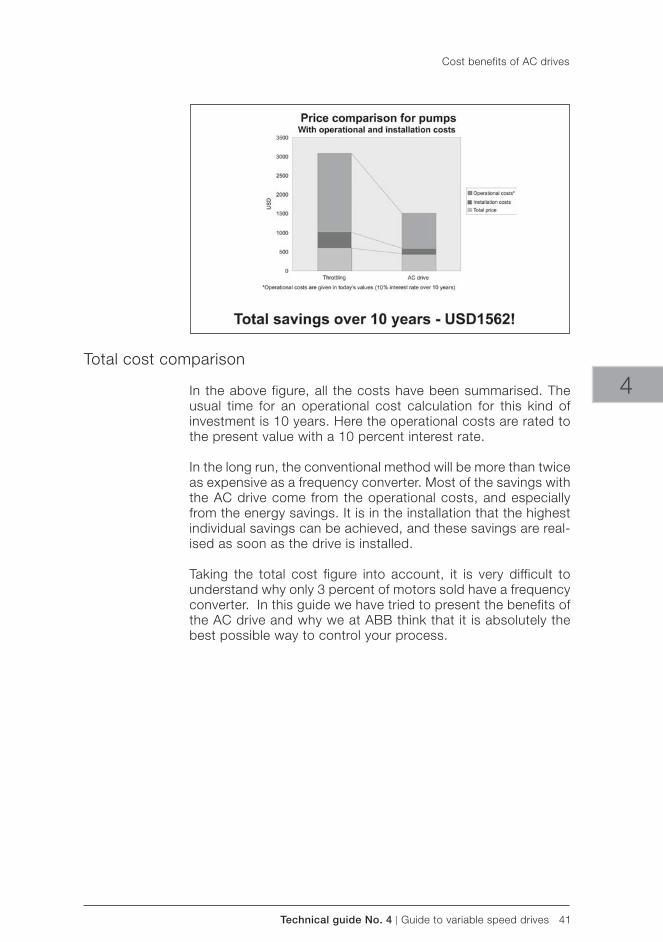
Technical guide No. 4 | Guide to variable speed drives 41
4Total cost comparison
In the above figure, all the costs have been summarised. The usual time for an operational cost calculation for this kind of investment is 10 years. Here the operational costs are rated to the present value with a 10 percent interest rate.
In the long run, the conventional method will be more than twice as expensive as a frequency converter. Most of the savings with the AC drive come from the operational costs, and especially from the energy savings. It is in the installation that the highest individual savings can be achieved, and these savings are real-ised as soon as the drive is installed.
Taking the total cost figure into account, it is very difficult to understand why only 3 percent of motors sold have a frequency converter. In this guide we have tried to present the benefits of the AC drive and why we at ABB think that it is absolutely the best possible way to control your process.
Cost benefits of AC drives
42 Guide to variable speed drives | Technical guide No. 4
Chapter 7 - Index
AABB 30, 33, 41AC drive 24, 25, 26, 27, 28, 29, 30, 31, 34, 35, 36, 37, 38, 39, 40, 41AC drives market 26AC motor 13, 14active power 16
Bbelt drives 24blowers 18braking 17, 23bypass control 22
Ccoefficient of efficiency 16Commissioning 39commutator 24, 26contactors 36crane 17, 19critical speed 30crusher 18current 14, 15, 16, 24
DDC bus 14, 15DC converter 24DC drive 24, 26DC motor 24, 26Direct on-line starting 25drive frequency 31drive software 31drive system 16, 20, 29, 33
Eelectrical disturbances 33electrical equipment room 24electrical supply 16, 27, 33electromagnetic compatibility 33electromagnetic induction 14, 15EMC 33EMC directives 33energy 14, 15, 22, 25, 26, 31, 37, 40, 41
Ffans 18flux 14, 15flying start 29, 32flywheel 32four quadrant drive 17frequency converter 14, 16, 17, 20, 24, 28, 32, 33, 34, 40, 41friction 18fuses 36
Hharbour 19hydraulic coupling 24
Iindustrial processes 13inertia 18, 32input power 16interference 15, 21inverter 14, 15, 24IP21 33IP54 33
Llinear ramp 30load capacity curves 28
Mmachine 11, 13, 24, 29magnetic flux 14, 15maintenance 24, 25, 26, 37, 40mechanical power 16mechanical vibrations 29, 30motor load 32motor losses 16motor phase 14motor size 16motor stall condition 31motor windings 14, 15
Nnuisance faults 29
Ooutput power 16
Ppower factor 16power loss ride-through 29, 31power plants 22, 37process control 25, 26, 27, 29processing system 10pump 24, 25, 36, 40
Rrated speed 16Reactive power 16reactive power 16reactors 36rectifier 14reference speed 30reversing function 29right hand rule 14

Technical guide No. 4 | Guide to variable speed drives 43
4
SS-ramp 30slip 14, 29, 32squirrel cage motor 20, 24, 33stall frequency 31stall function 29, 31stator 14stepless control 15
Ttemperature 15, 33throttling 22, 36, 39, 40torque 16, 17, 18, 19, 20, 28, 29, 30, 31, 32transistors 16
Vvalve 40valves 24, 36variable speed control 8, 21, 24variable speed drives 1, 3voltage 14, 15, 16, 24, 27, 31VSD 9, 15, 22, 23, 24, 25, 26
Index

44 Guide to variable speed drives | Technical guide No. 4

3AFE
6138
9211
RE
V C
EN
12.
5.20
11 #
1567
7
Contact us
For more information please contact your local ABB representative or visit:
www.abb.com/driveswww.abb.com/drivespartners
© Copyright 2011 ABB. All rights reserved. Specifications subject to change without notice.

Technical guide No. 5Bearing currents in modern AC drive systems
ABB drives

2 Bearing currents in modern AC drive systems | Technical guide No. 5

Technical guide No. 5 | Bearing currents in modern AC drive systems 3
© Copyright 2011 ABB. All rights reserved.
Specifications subject to change without notice.
3AFE64230247 REV C EN 27.4.2011
Technical guide No. 5Bearing currents in modern AC drive systems
5

4 Bearing currents in modern AC drive systems | Technical guide No. 5

Technical guide No. 5 | Bearing currents in modern AC drive systems 5
5
Contents
Chapter 1 - Introduction ............................................................................7
General .............................................................................................7Avoiding bearing currents ..................................................................7
Chapter 2 - Generating bearing currents ...................................................8
High frequency current pulses ............................................................8Faster switching ................................................................................9How are HF bearing currents generated? .............................................9
Circulating current ........................................................................9Shaft grounding current .................................................................9Capacitive discharge current ........................................................10
Common mode circuit ......................................................................10Stray capacitances ..........................................................................11How does the current flow through the system? ................................12Voltage drops ...................................................................................13Common mode transformer ..............................................................14Capacitive voltage divider .................................................................15
Chapter 3 - Preventing high frequency bearing current damage .............17
Three approaches ............................................................................17Multicore motor cables .................................................................17Short impedance path .................................................................17High frequency bonding connections ...........................................18
Follow product specific instructions ..................................................19Additional solutions .....................................................................19
Measuring high frequency bearing currents ........................................19Leave the measurements to the specialists ........................................20
Chapter 4 - References ............................................................................21
Chapter 5 - Index .....................................................................................22

6 Bearing currents in modern AC drive systems | Technical guide No. 5
Technical guide No. 5 | Bearing currents in modern AC drive systems 7
5
Chapter 1 - Introduction
General
Some new drive installations can have their bearings fail only a few months after startup. Failure can be caused by high fre-quency currents, which flow through the motor bearings.
While bearing currents have been around since the advent of electric motors, the incidence of damage they cause has increased during the last few years. This is because modern variable speed drives with their fast rising voltage pulses and high switching frequencies can cause current pulses through the bearings whose repeated discharging can gradually erode the bearing races.
Avoiding bearing currents
To avoid damage occurring, it is essential to provide proper earthing paths and allow stray currents to return to the inverter frame without passing through the bearings. The magnitude of the currents can be reduced by using symmetrical motor cables or inverter output filtering. Proper insulation of the motor bearing construction breaks the bearing current paths.
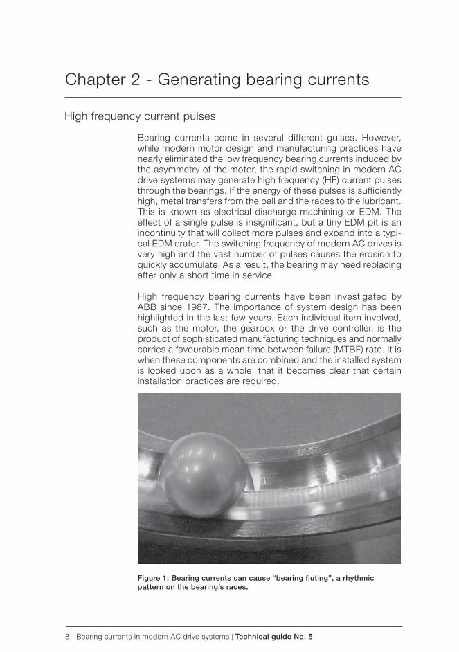
8 Bearing currents in modern AC drive systems | Technical guide No. 5
Chapter 2 - Generating bearing currents
High frequency current pulses
Bearing currents come in several different guises. However, while modern motor design and manufacturing practices have nearly eliminated the low frequency bearing currents induced by the asymmetry of the motor, the rapid switching in modern AC drive systems may generate high frequency (HF) current pulses through the bearings. If the energy of these pulses is sufficiently high, metal transfers from the ball and the races to the lubricant. This is known as electrical discharge machining or EDM. The effect of a single pulse is insignificant, but a tiny EDM pit is an incontinuity that will collect more pulses and expand into a typi-cal EDM crater. The switching frequency of modern AC drives is very high and the vast number of pulses causes the erosion to quickly accumulate. As a result, the bearing may need replacing after only a short time in service.
High frequency bearing currents have been investigated by ABB since 1987. The importance of system design has been highlighted in the last few years. Each individual item involved, such as the motor, the gearbox or the drive controller, is the product of sophisticated manufacturing techniques and normally carries a favourable mean time between failure (MTBF) rate. It is when these components are combined and the installed system is looked upon as a whole, that it becomes clear that certain installation practices are required.
Figure 1: Bearing currents can cause “ bearing fluting”, a rhythmic pattern on the bearing’s races.
Technical guide No. 5 | Bearing currents in modern AC drive systems 9
5
Faster switching
Current AC drive technology, incorporating insulated gate bipo-lar transistors (IGBT), creates switching events 20 times faster than those considered typical ten years ago. Recent years have seen a rising number of EDM-type bearing failures in AC drive systems relatively soon after startup, within one to six months. The extent to which this occurs depends on the AC drive system architecture and the installation techniques used.
How are HF bearing currents generated?
The source of bearing currents is the voltage that is induced over the bearing. In the case of high frequency bearing currents, this voltage can be generated in three different ways. The most important factors that define which mechanism is prominent, are the size of the motor and how the motor frame and shaft are grounded. The electrical installation, meaning a suitable cable type and proper bonding of the protective conductors and the electrical shield, plays an important role. Du/dt of the AC drive power stage components and the DC-link voltage level affect the level of bearing currents.
Circulating current
In large motors, high frequency voltage is induced between the ends of the motor shaft by the high frequency flux circulating around the stator. This flux is caused by a net asymmetry of capacitive current leaking from the winding into the stator frame along the stator circumference. The voltage between the shaft ends affects the bearings. If it is high enough to overcome the impedance of the bearings’ oil film, a current that tries to com-pensate the net flux in the stator starts to flow in the loop formed by the shaft, the bearings and the stator frame. This current is a circulating type of high frequency bearing current.
Shaft grounding current
The current leaking into the stator frame needs to flow back to the inverter, which is the source of this current. Any route back contains impedance, and therefore the voltage of the motor frame increases in comparison to the source ground level. If the motor shaft is earthed via the driven machinery, the increase of the motor frame voltage is seen over the bearings. If the voltage rises high enough to overcome the impedance of the drive-end bearing oil film, part of the current may flow via the drive-end bearing, the shaft and the driven machine back to the inverter. This current is a shaft grounding type of high frequency bearing current.
Generating bearing currents
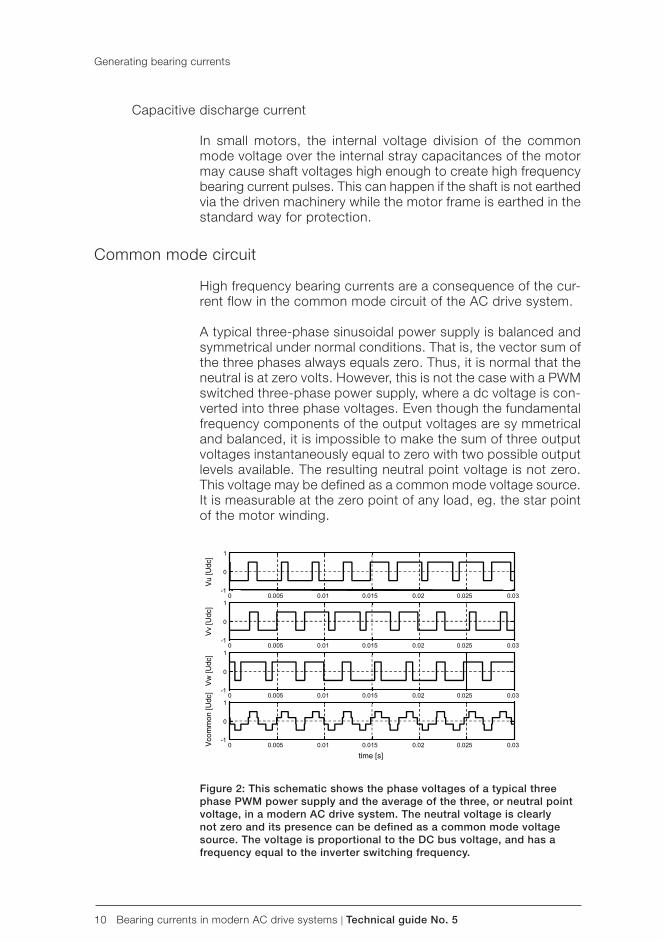
10 Bearing currents in modern AC drive systems | Technical guide No. 5
Capacitive discharge current In small motors, the internal voltage division of the common mode voltage over the internal stray capacitances of the motor may cause shaft voltages high enough to create high frequency bearing current pulses. This can happen if the shaft is not earthed via the driven machinery while the motor frame is earthed in the standard way for protection.
Common mode circuit
High frequency bearing currents are a consequence of the cur-rent flow in the common mode circuit of the AC drive system.
A typical three-phase sinusoidal power supply is balanced and symmetrical under normal conditions. That is, the vector sum of the three phases always equals zero. Thus, it is normal that the neutral is at zero volts. However, this is not the case with a PWM switched three-phase power supply, where a dc voltage is con-verted into three phase voltages. Even though the fundamental frequency components of the output voltages are sy mmetrical and balanced, it is impossible to make the sum of three output voltages instantaneously equal to zero with two possible output levels available. The resulting neutral point voltage is not zero. This voltage may be defined as a common mode voltage source. It is measurable at the zero point of any load, eg. the star point of the motor winding.
Figure 2: This schematic shows the phase voltages of a typical three phase PWM power supply and the average of the three, or neutral point voltage, in a modern AC drive system. The neutral voltage is clearly not zero and its presence can be defined as a common mode voltage source. The voltage is proportional to the DC bus voltage, and has a frequency equal to the inverter switching frequency.
Generating bearing currents
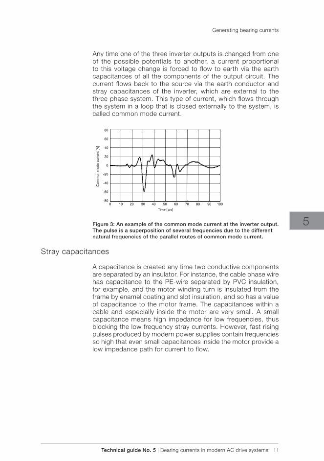
Technical guide No. 5 | Bearing currents in modern AC drive systems 11
5Figure 3: An example of the common mode current at the inverter output. The pulse is a superposition of several frequencies due to the different natural frequencies of the parallel routes of common mode current.
Stray capacitances
A capacitance is created any time two conductive components are separated by an insulator. For instance, the cable phase wire has capacitance to the PE-wire separated by PVC insulation, for example, and the motor winding turn is insulated from the frame by enamel coating and slot insulation, and so has a value of capacitance to the motor frame. The capacitances within a cable and especially inside the motor are very small. A small capacitance means high impedance for low frequencies, thus blocking the low frequency stray currents. However, fast rising pulses produced by modern power supplies contain frequencies so high that even small capacitances inside the motor provide a low impedance path for current to flow.
Any time one of the three inverter outputs is changed from one of the possible potentials to another, a current proportional to this voltage change is forced to flow to earth via the earth capacitances of all the components of the output circuit. The current flows back to the source via the earth conductor and stray capacitances of the inverter, which are external to the three phase system. This type of current, which flows through the system in a loop that is closed externally to the system, is called common mode current.
Generating bearing currents
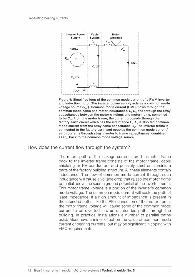
12 Bearing currents in modern AC drive systems | Technical guide No. 5
Figure 4: Simplified loop of the common mode current of a PWM inverter and induction motor. The inverter power supply acts as a common mode voltage source (Vcm). Common mode current (CMC) flows through the common mode cable and motor inductances, Lc Lm and through the stray capacitances between the motor windings and motor frame, combined to be Cm. From the motor frame, the current proceeds through the factory earth circuit which has the inductance Lg. Lg is also fed common mode current from the stray cable capacitance Cc. The inverter frame is connected to the factory earth and couples the common mode current/earth currents through stray inverter to frame capacitances, combined as Cin, back to the common mode voltage source.
How does the current flow through the system? The return path of the leakage current from the motor frame back to the inverter frame consists of the motor frame, cable shielding or PE-conductors and possibly steel or aluminium parts of the factory building structure. All these elements contain inductance. The flow of common mode current through such inductance will cause a voltage drop that raises the motor frame potential above the source ground potential at the inverter frame. This motor frame voltage is a portion of the inverter’s common mode voltage. The common mode current will seek the path of least impedance. If a high amount of impedance is present in the intended paths, like the PE-connection of the motor frame, the motor frame voltage will cause some of the common mode current to be diverted into an unintended path, through the building. In practical installations a number of parallel paths exist. Most have a minor effect on the value of common mode current or bearing currents, but may be significant in coping with EMC-requirements.
Generating bearing currents
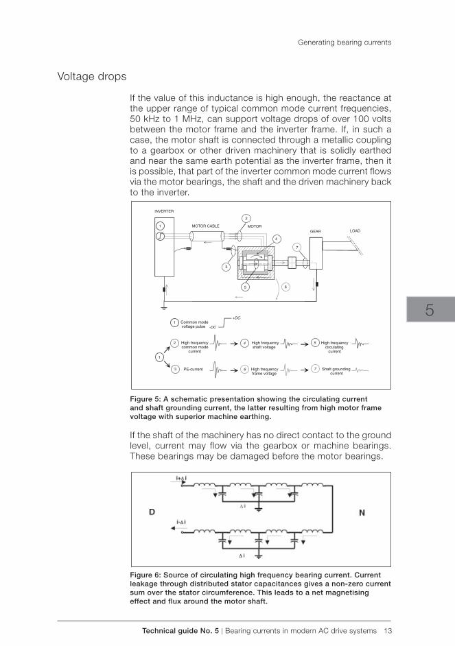
Technical guide No. 5 | Bearing currents in modern AC drive systems 13
5
Voltage drops If the value of this inductance is high enough, the reactance at the upper range of typical common mode current frequencies, 50 kHz to 1 MHz, can support voltage drops of over 100 volts between the motor frame and the inverter frame. If, in such a case, the motor shaft is connected through a metallic coupling to a gearbox or other driven machinery that is solidly earthed and near the same earth potential as the inverter frame, then it is possible, that part of the inverter common mode current flows via the motor bearings, the shaft and the driven machinery back to the inverter.
Figure 5: A schematic presentation showing the circulating current and shaft grounding current, the latter resulting from high motor frame voltage with superior machine earthing.
If the shaft of the machinery has no direct contact to the ground level, current may flow via the gearbox or machine bearings. These bearings may be damaged before the motor bearings.
Figure 6: Source of circulating high frequency bearing current. Current leakage through distributed stator capacitances gives a non-zero current sum over the stator circumference. This leads to a net magnetising effect and flux around the motor shaft.
Generating bearing currents
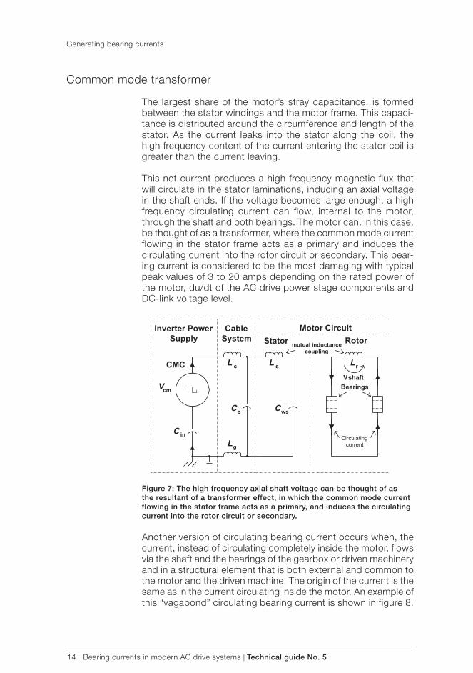
14 Bearing currents in modern AC drive systems | Technical guide No. 5
Common mode transformer The largest share of the motor’s stray capacitance, is formed between the stator windings and the motor frame. This capaci-tance is distributed around the circumference and length of the stator. As the current leaks into the stator along the coil, the high frequency content of the current entering the stator coil is greater than the current leaving.
This net current produces a high frequency magnetic flux that will circulate in the stator laminations, inducing an axial voltage in the shaft ends. If the voltage becomes large enough, a high frequency circulating current can flow, internal to the motor, through the shaft and both bearings. The motor can, in this case, be thought of as a transformer, where the common mode current flowing in the stator frame acts as a primary and induces the circulating current into the rotor circuit or secondary. This bear-ing current is considered to be the most damaging with typical peak values of 3 to 20 amps depending on the rated power of the motor, du/dt of the AC drive power stage components and DC-link voltage level.
Figure 7: The high frequency axial shaft voltage can be thought of as the resultant of a transformer effect, in which the common mode current flowing in the stator frame acts as a primary, and induces the circulating current into the rotor circuit or secondary.
Another version of circulating bearing current occurs when, the current, instead of circulating completely inside the motor, flows via the shaft and the bearings of the gearbox or driven machinery and in a structural element that is both external and common to the motor and the driven machine. The origin of the current is the same as in the current circulating inside the motor. An example of this “vagabond” circulating bearing current is shown in figure 8.
Generating bearing currents
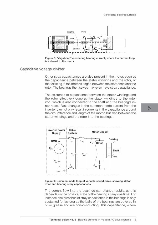
Technical guide No. 5 | Bearing currents in modern AC drive systems 15
5
Generating bearing currents
Figure 8: “Vagabond” circulating bearing current, where the current loop is external to the motor.
Capacitive voltage divider Other stray capacitances are also present in the motor, such as the capacitance between the stator windings and the rotor, or that existing in the motor’s airgap between the stator iron and the rotor. The bearings themselves may even have stray capacitance.
The existence of capacitance between the stator windings and the rotor effectively couples the stator windings to the rotor iron, which is also connected to the shaft and the bearing’s in-ner races. Fast changes in the common mode current from the inverter can not only result in currents in the capacitance around the circumference and length of the motor, but also between the stator windings and the rotor into the bearings.
Figure 9: Common mode loop of variable speed drive, showing stator, rotor and bearing stray capacitances.
The current flow into the bearings can change rapidly, as this depends on the physical state of the bearing at any one time. For instance, the presence of stray capacitance in the bearings is only sustained for as long as the balls of the bearings are covered in oil or grease and are non-conducting. This capacitance, where

16 Bearing currents in modern AC drive systems | Technical guide No. 5
the induced shaft voltage builds up, can be short-circuited if the bearing voltage exceeds the threshold of its breakover value or if a “high spot” on a ball breaks through the oil film and makes contact with both bearing races. At very low speed, the bearings have metallic contact since the balls have not risen on an oil film.
Generally, the bearing impedance governs the voltage level at which the bearings start to conduct. This impedance is a non-linear function of bearing load, temperature, speed of rotation and lubricant used, and the impedance varies from case to case.
Generating bearing currents
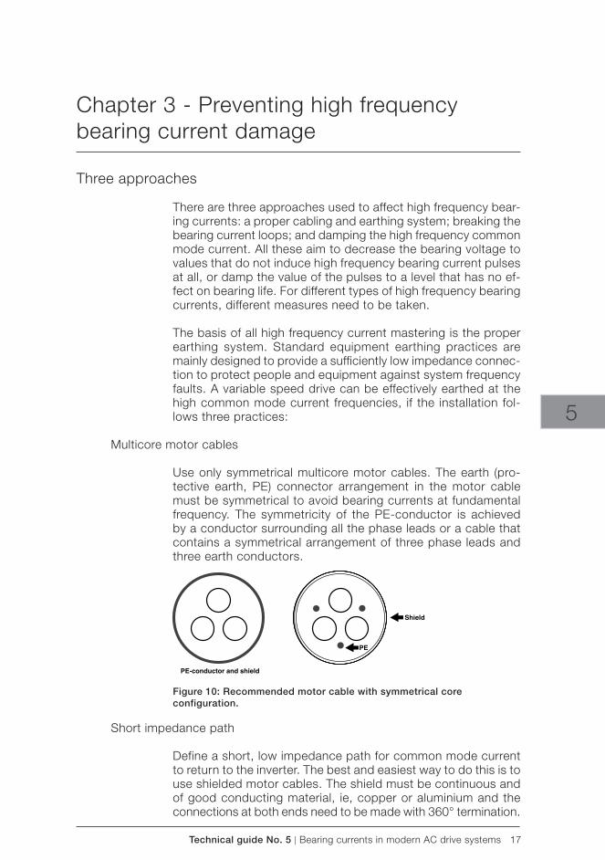
Technical guide No. 5 | Bearing currents in modern AC drive systems 17
5
Chapter 3 - Preventing high frequency bearing current damage
Three approaches There are three approaches used to affect high frequency bear-ing currents: a proper cabling and earthing system; breaking the bearing current loops; and damping the high frequency common mode current. All these aim to decrease the bearing voltage to values that do not induce high frequency bearing current pulses at all, or damp the value of the pulses to a level that has no ef-fect on bearing life. For different types of high frequency bearing currents, different measures need to be taken.
The basis of all high frequency current mastering is the proper earthing system. Standard equipment earthing practices are mainly designed to provide a sufficiently low impedance connec-tion to protect people and equipment against system frequency faults. A variable speed drive can be effectively earthed at the high common mode current frequencies, if the installation fol-lows three practices:
Multicore motor cables Use only symmetrical multicore motor cables. The earth (pro-tective earth, PE) connector arrangement in the motor cable must be symmetrical to avoid bearing currents at fundamental frequency. The symmetricity of the PE-conductor is achieved by a conductor surrounding all the phase leads or a cable that contains a symmetrical arrangement of three phase leads and three earth conductors.
Figure 10: Recommended motor cable with symmetrical core configuration.
Short impedance path
Define a short, low impedance path for common mode current to return to the inverter. The best and easiest way to do this is to use shielded motor cables. The shield must be continuous and of good conducting material, ie, copper or aluminium and the connections at both ends need to be made with 360° termination.
18 Bearing currents in modern AC drive systems | Technical guide No. 5
Preventing high frequency bearing current damage
Figures 11a and 11b show 360° terminations for European and American cabling practices.
Figure 11 a: Proper 360° termination with European cabling practice. The shield is connected with as short a pigtail as possible to the PE terminal. To make a 360° high frequency connection between the EMC sleeve and the cable shield, the outer insulation of the cable is stripped away.
Figure 11 b: Proper 360° termination with American cabling practice. An earthing bushing should be used on both ends of the motor cable to effectively connect the earth wires to the armour or conduit.
High frequency bonding connections
Add high frequency bonding connections between the installa-tion and known earth reference points to equalise the potential of affected items, using braided straps of copper 50 - 100 mm wide; flat conductors will provide a lower inductance path than round wires. This must be made at the points where discontinu-ity between the earth level of the inverter and that of the mo-tor is suspected. Additionally it may be necessary to equalise the potential between the frames of the motor and the driven machinery to short the current path through the motor and the driven machine bearings.
Technical guide No. 5 | Bearing currents in modern AC drive systems 19
5
Figure 12: HF bonding strap
Follow product specific instructions
Although the basic principles of installations are the same, for different products suitable installation practices may differ. There-fore, it is essential to carefully follow the installation instructions given in product specific manuals.
Additional solutions
Breaking the bearing current loops is achieved by insulating the bearing construction. The high frequency common mode current can be damped by using dedicated filters. As a manufacturer of both inverters and motors, ABB can offer the most appropriate solution in each case as well as detailed instructions on proper earthing and cabling practices.
Measuring high frequency bearing currents
Monitoring the bearing condition must be conducted with es-tablished vibration measurements.
It is impossible to measure bearing currents directly from a standard motor. But if high frequency bearing currents are suspected, field measurements can be taken to verify the exist-ence of suspected current loops. Measuring equipment needs to have wide bandwidth (minimum 10 kHz to 2 MHz) capable of detecting peak values of at least 150 to 200 A and RMS values at least down to 10 mA. The crest factor of measured signals is seldom less than 20. The current may flow in unusual places, such as rotating shafts. Thus, special equipment and experienced personnel are needed.
ABB uses a specially designed, flexible, air-cored, Rogowski-type current sensor with dedicated accessories and has vast experience of over one thousand measured drives in different applications worldwide.
Preventing high frequency bearing current damage
20 Bearing currents in modern AC drive systems | Technical guide No. 5
The most important measurement points are within the motor. During measurements, the motor speed needs to be at least 10 percent of the nominal for the bearings to rise on the oil film. As an example, basic measurements are shown in figure 13. Figure 14 shows examples of measured current waveforms. GTO (gate turn-off thyristor) inverters were used mainly in the 1980s and IGBT inverters are used today. Note the different scale in the various graphs.
Figure 13: Basic measurements: A) circulating current measured with a jumper, B) shaft grounding current.
A) Circulating current
GTO-inverter, 5 μs/div, 2 A/div IGBT-inverter, 5 μs/div, 2 A/div
B) Shaft grounding current
GTO-inverter, 2 μs/div, 10 A/div IGBT-inverter, 5 μs/div, 500 mA/div
Figure 14: Examples of current waveforms at the measuring points shown in Figure 13.
Leave the measurements to the specialists
Since suitable commercial measurement equipment is not available on the market and specialised experience is needed to make the measurements and interpret the results, it is advis-able that bearing current measurements are made by dedicated personnel only.
Preventing high frequency bearing current damage
Technical guide No. 5 | Bearing currents in modern AC drive systems 21
5
Chapter 4 - References
1. Grounding and Cabling of the Drive System, ABB Industry Oy, 3AFY 61201998 R0125
2. A New Reason for Bearing Current Damage in Variable Speed AC Drives
by J. Ollila, T. Hammar, J. Iisakkala, H. Tuusa. EPE 97, 7th European Conference on Power Electronics and Applica-tions, 8-10 September 1997. Trondheim, Norway.
3. On the Bearing Currents in Medium Power Variable Speed AC Drives
by J. Ollila, T. Hammar, J. Iisakkala, H. Tuusa. proceedings of the IEEE IEDMC in Milwaukee, May 1997.
4. Minimizing Electrical Bearing Currents in Adjustable Speed Drive Systems
by Patrick Link. IEEE IAS Pulp & Paper Conference Portland, ME, USA. June 1998.
5. Instruction on Measuring Bearing Currents with a Rogowski Coil, ABB Industry Oy, 3BFA 61363602.EN.
6. Laakerivirta ja sen minimoiminen säädettyjen vaihto-virtakäyttöjen moottoreissa,
I. Erkkilä, Automaatio 1999, 16.9.1999, Helsinki, Finland. (In Finnish).
7. High Frequency Bearing Currents in Low Voltage Asynchronous Motors,
ABB Motors Oy and ABB Industry Oy, 00018323.doc.
8. Bearing Currents in AC Drives by ABB Industry Oy and ABB Motors Oy. Set of overheads
in LN database “Document Directory Intranet” on ABB_FI01_SPK08/FI01/ABB
9. The Motor Guide GB 98-12.
See also product specific installation manuals.
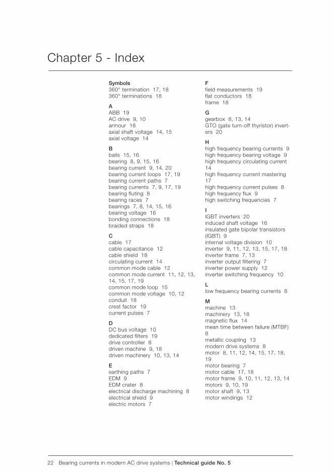
22 Bearing currents in modern AC drive systems | Technical guide No. 5
Chapter 5 - Index
Symbols360° termination 17, 18360° terminations 18
AABB 19AC drive 9, 10armour 18axial shaft voltage 14, 15axial voltage 14
Bballs 15, 16bearing 8, 9, 15, 16bearing current 9, 14, 20bearing current loops 17, 19bearing current paths 7bearing currents 7, 9, 17, 19bearing fluting 8bearing races 7bearings 7, 8, 14, 15, 16bearing voltage 16bonding connections 18braided straps 18
Ccable 17cable capacitance 12cable shield 18circulating current 14common mode cable 12common mode current 11, 12, 13, 14, 15, 17, 19common mode loop 15common mode voltage 10, 12conduit 18crest factor 19current pulses 7
DDC bus voltage 10dedicated filters 19drive controller 8driven machine 9, 18driven machinery 10, 13, 14
Eearthing paths 7EDM 9EDM crater 8electrical discharge machining 8electrical shield 9electric motors 7
Ffield measurements 19flat conductors 18frame 18
Ggearbox 8, 13, 14GTO (gate turn-off thyristor) invert-ers 20
Hhigh frequency bearing currents 9high frequency bearing voltage 9high frequency circulating current 14high frequency current mastering 17high frequency current pulses 8high frequency flux 9high switching frequencies 7
IIGBT inverters 20induced shaft voltage 16insulated gate bipolar transistors (IGBT) 9internal voltage division 10inverter 9, 11, 12, 13, 15, 17, 18inverter frame 7, 13inverter output filtering 7inverter power supply 12inverter switching frequency 10
Llow frequency bearing currents 8
Mmachine 13machinery 13, 18magnetic flux 14mean time between failure (MTBF) 8metallic coupling 13modern drive systems 8motor 8, 11, 12, 14, 15, 17, 18, 19motor bearing 7motor cable 17, 18motor frame 9, 10, 11, 12, 13, 14motors 9, 10, 19motor shaft 9, 13motor windings 12

Technical guide No. 5 | Bearing currents in modern AC drive systems 23
5
Nneutral point voltage 10
Ooil film 9, 20
Pprimary 14PWM 10, 12
Rraces 8, 16Rogowski-type current sensor 19rotor 14, 15rotor circuit 14
Ssecondary 14shaft 10, 14, 15shaft ends 14shaft voltages 10shield 17stator 9, 14, 15stator frame 9, 13, 14stator laminations 14stator windings 14, 15stray capacitance 10, 11, 12, 14, 15stray currents 7symmetrical motor cables 7symmetrical multicore motor cables 17
Tthree-phase sinusoidal power supply 10three phase power supply 10transformer 14
Vvariable speed drive 15, 17voltage drop 12, 13voltage pulses 7
Wwinding 9, 10, 11, 12, 14, 15
Index

24 Bearing currents in modern AC drive systems | Technical guide No. 5

3AFE
6423
0247
RE
V C
EN
27.
4.20
11 #
1564
8
Contact us
For more information please contact your local ABB representative or visit:
www.abb.com/driveswww.abb.com/drivespartners
© Copyright 2011 ABB. All rights reserved. Specifications subject to change without notice.

Technical guide No. 6Guide to harmonics with AC drives
ABB drives

2 Guide to harmonics with AC drives | Technical guide No. 6

Technical guide No. 6 | Guide to harmonics with AC drives 3
© Copyright 2013 ABB. All rights reserved.
Specifications subject to change without notice.
3AFE64292714 REV D EN 11.2.2013
Technical guide No. 6Guide to harmonics with AC drives
6

4 Guide to harmonics with AC drives | Technical guide No. 6
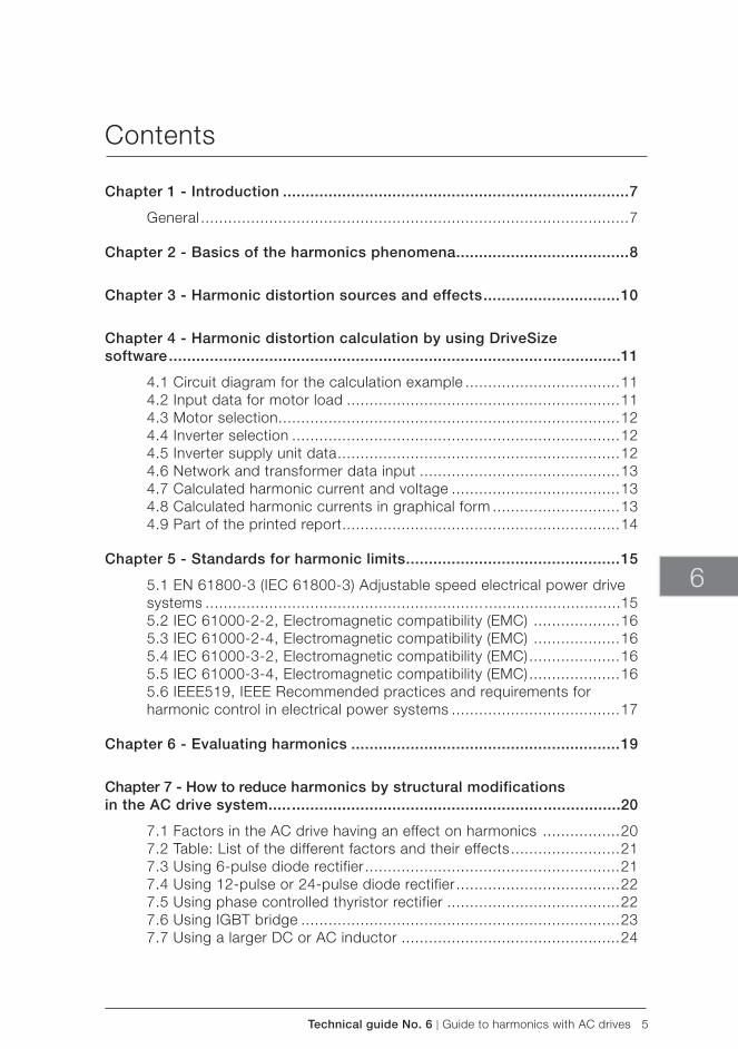
Technical guide No. 6 | Guide to harmonics with AC drives 5
6
Contents
Chapter 1 - Introduction ............................................................................7
General ..............................................................................................7
Chapter 2 - Basics of the harmonics phenomena ......................................8
Chapter 3 - Harmonic distortion sources and effects ..............................10
Chapter 4 - Harmonic distortion calculation by using DriveSize software .................................................................................. .................11
4.1 Circuit diagram for the calculation example ..................................114.2 Input data for motor load ............................................................114.3 Motor selection ...........................................................................124.4 Inverter selection ........................................................................124.5 Inverter supply unit data ..............................................................124.6 Network and transformer data input ............................................134.7 Calculated harmonic current and voltage .....................................134.8 Calculated harmonic currents in graphical form ............................134.9 Part of the printed report .............................................................14
Chapter 5 - Standards for harmonic limits ...............................................15
5.1 EN 61800-3 (IEC 61800-3) Adjustable speed electrical power drive systems ............................................................. ..............................155.2 IEC 61000-2-2, Electromagnetic compatibility (EMC) ...................165.3 IEC 61000-2-4, Electromagnetic compatibility (EMC) ...................165.4 IEC 61000-3-2, Electromagnetic compatibility (EMC) ....................165.5 IEC 61000-3-4, Electromagnetic compatibility (EMC) ....................165.6 IEEE519, IEEE Recommended practices and requirements for harmonic control in electrical power systems .....................................17
Chapter 6 - Evaluating harmonics ...........................................................19
Chapter 7 - How to reduce harmonics by structural modifications in the AC drive system..... ....................................................... .................20
7.1 Factors in the AC drive having an effect on harmonics .................207.2 Table: List of the different factors and their effects ........................217.3 Using 6-pulse diode rectifier ........................................................217.4 Using 12-pulse or 24-pulse diode rectifier ....................................227.5 Using phase controlled thyristor rectifier ......................................227.6 Using IGBT bridge ......................................................................237.7 Using a larger DC or AC inductor ................................................24
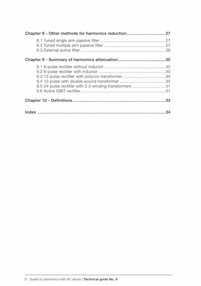
6 Guide to harmonics with AC drives | Technical guide No. 6
Chapter 8 - Other methods for harmonics reduction ...............................27
8.1 Tuned single arm passive filter ....................................................278.2 Tuned multiple arm passive filter .................................................278.3 External active filter ....................................................................28
Chapter 9 - Summary of harmonics attenuation ......................................30
9.1 6-pulse rectifier without inductor .................................................309.2 6-pulse rectifier with inductor ......................................................309.3 12-pulse rectifier with polycon transformer ...................................309.4 12-pulse with double wound transformer .....................................309.5 24-pulse rectifier with 2 3-winding transformers ...........................319.6 Active IGBT rectifier ....................................................................31
Chapter 10 - Definitions ...........................................................................32
Index .......................................................................................................34

Technical guide No. 6 | Guide to harmonics with AC drives 7
6
Chapter 1 - Introduction
General
This guide continues ABB’s technical guide series, describing harmonic distortion, its sources and effects, and also distortion calculation and evaluation. Special attention has been given to the methods for reducing harmonics with AC drives.
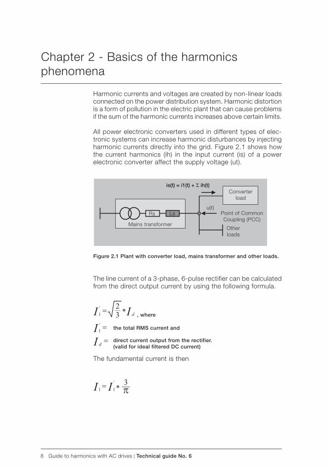
8 Guide to harmonics with AC drives | Technical guide No. 6
, where
the total RMS current and
direct current output from the rectifier.(valid for ideal filtered DC current)
is(t) = i1(t) + Σ ih(t)Converter
load
Other loads
Point of Common Coupling (PCC)
Mains transformer
Rs Lsu(t)
Chapter 2 - Basics of the harmonics phenomena
Harmonic currents and voltages are created by non-linear loads connected on the power distribution system. Harmonic distortion is a form of pollution in the electric plant that can cause problems if the sum of the harmonic currents increases above certain limits.
All power electronic converters used in different types of elec-tronic systems can increase harmonic disturbances by injecting harmonic currents directly into the grid. Figure 2.1 shows how the current harmonics (ih) in the input current (is) of a power electronic converter affect the supply voltage (ut).
Figure 2.1 Plant with converter load, mains transformer and other loads.
The line current of a 3-phase, 6-pulse rectifier can be calculated from the direct output current by using the following formula.
The fundamental current is then
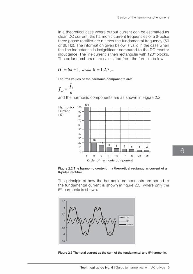
Technical guide No. 6 | Guide to harmonics with AC drives 9
Order of harmonic component
Harmonic-Current (%)
The rms values of the harmonic components are:
where
6
In a theoretical case where output current can be estimated as clean DC current, the harmonic current frequencies of a 6-pulse three phase rectifier are n times the fundamental frequency (50 or 60 Hz). The information given below is valid in the case when the line inductance is insignificant compared to the DC reactor inductance. The line current is then rectangular with 120° blocks. The order numbers n are calculated from the formula below:
Basics of the harmonics phenomena
and the harmonic components are as shown in Figure 2.2.
Figure 2.2 The harmonic content in a theoretical rectangular current of a 6-pulse rectifier.
The principle of how the harmonic components are added to the fundamental current is shown in figure 2.3, where only the 5th harmonic is shown.
Figure 2.3 The total current as the sum of the fundamental and 5th harmonic.
10 Guide to harmonics with AC drives | Technical guide No. 6
Chapter 3 - Harmonic distortion sources and effects
Common non-linear loads include motor starters, variable speed drives, computers and other electronic devices, electronic light-ing, welding supplies and uninterrupted power supplies.
The effects of harmonics can be overheating of transformers, cables, motors, generators and capacitors connected to the same power supply with the devices generating the harmonics. Electronic displays and lighting may flicker, circuit breakers can trip, computers may fail and metering can give false readings.
If the cause of the above mentioned symptoms is not known, then there is cause to investigate the harmonic distortion of the electricity distribution at the plant. The effects are likely to show up in the customer’s plant before they show on the utility system. This Technical guide has been published to help customers to understand the possible harmonic problems and make sure the harmonic distortion levels are not excessive.
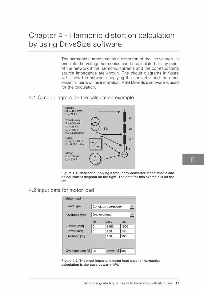
Technical guide No. 6 | Guide to harmonics with AC drives 11
SupplySk = 150 MVAU = 22 kV
Transformer:S = 400 kVAU1 = 22 kVU2 = 415 Vz = 4,5 percent
Cable:Length = 60 mR = 0,007 mΩ/m
Motor:P = 100 kWIN = 200 A
S’k
Xk
Xt
X’k
I
Motor load
Load type
Overload type
Speed [rpm]
Power [kW]
Overload [%]
Const. torque/power
One overload
min base max
0
0
1450
100
100
100
100
1500
60 600Overload time [s] every [s]
6
Chapter 4 - Harmonic distortion calculation by using DriveSize software
The harmonic currents cause a distortion of the line voltage. In principle the voltage harmonics can be calculated at any point of the network if the harmonic currents and the corresponding source impedance are known. The circuit diagrams in figure 4.1. show the network supplying the converter and the other essential parts of the installation. ABB DriveSize software is used for the calculation.
4.1 Circuit diagram for the calculation example
Figure 4.1. Network supplying a frequency converter in the middle and its equivalent diagram on the right. The data for this example is on the left.
4.2 Input data for motor load
Figure 4.2. The most important motor load data for harmonics calculation is the base power in kW.
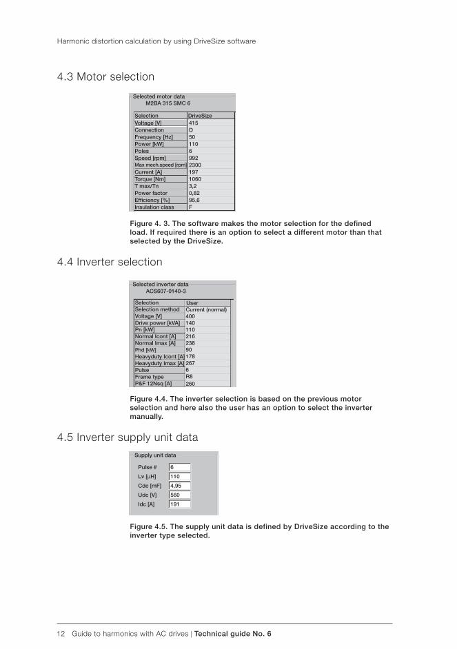
12 Guide to harmonics with AC drives | Technical guide No. 6
Selected motor dataM2BA 315 SMC 6
Selection Voltage [V]Connection Frequency [Hz]Power [kW]PolesSpeed [rpm]Max mech.speed [rpm]Current [A]Torque [Nm]T max/Tn Power factorEffi ciency [%]Insulation class
DriveSize415D50110
9926
230019710603,20,8295,6F
SelectionSelection method Voltage [V]Drive power [kVA]Pn [kW]Normal Icont [A] Normal Imax [A]Phd [kW]Heavyduty Icont [A]Heavyduty Imax [A]PulseFrame typeP&F 12Nsq [A]
Selected inverter dataACS607-0140-3
UserCurrent (normal) 400140110
238216
901782676R8260
Supply unit data
Pulse #
Lv [μH]
Cdc [mF]
Udc [V]
Idc [A]
6
110
4,95
560
191
Figure 4.5. The supply unit data is defined by DriveSize according to the inverter type selected.
4.3 Motor selection
Figure 4. 3. The software makes the motor selection for the defined load. If required there is an option to select a different motor than that selected by the DriveSize.
4.4 Inverter selection
Figure 4.4. The inverter selection is based on the previous motor selection and here also the user has an option to select the inverter manually.
4.5 Inverter supply unit data
Harmonic distortion calculation by using DriveSize software
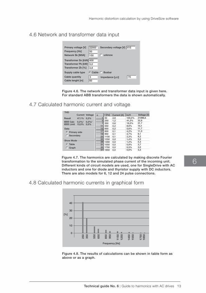
Technical guide No. 6 | Guide to harmonics with AC drives 13
Network and Transformer data
Primary voltage [V] Secondary voltage [V]
Frequency [Hz]
Network Sk [MVA]
Transformer Sn [kVA] Transformer Pk [kW]
Transformer Zk [%]
Supply cable type Cable Busbar
Cable quantityCable lenght [m]
Impedance [μΩ]
unknow
22000
50
150
400
3,0
3,8
360
415
70
THD
Data
Show Mode
VoltageCurrent
Result
IEEE CalcIEEE Limit
47,1% 0,2%
0,2%/ 0,2%/15,0% 0,5%
Primary sideSecondary
Table
Graph
n157
11131719232529313537
50250350550650850950115012501450155017501850
2,81,20,60,20,20,10,10,10,00,00,00,00,0
100,0%
0,6%
41,2%19,5%8,6%5,6%4,2%2,7%2,3%1,4%1,2%0,8%0,5%
21996,632,921,715,111,711,38,18,25,55,33,73,03,3
f [Hz] Current [A] In/I1 Voltage [V]
50
[%]
Frequency [Hz]
40
30
20
10
0
250
350
550
650
850
950
1150
1250
1450
1550
1750
1850
6
4.6 Network and transformer data input
Figure 4.6. The network and transformer data input is given here.For standard ABB transformers the data is shown automatically.
4.7 Calculated harmonic current and voltage
Figure 4.7. The harmonics are calculated by making discrete Fourier transformation to the simulated phase current of the incoming unit.Different kinds of circuit models are used, one for SingleDrive with AC inductors and one for diode and thyristor supply with DC inductors.There are also models for 6, 12 and 24 pulse connections.
4.8 Calculated harmonic currents in graphical form
Figure 4.8. The results of calculations can be shown in table form asabove or as a graph.
Harmonic distortion calculation by using DriveSize software
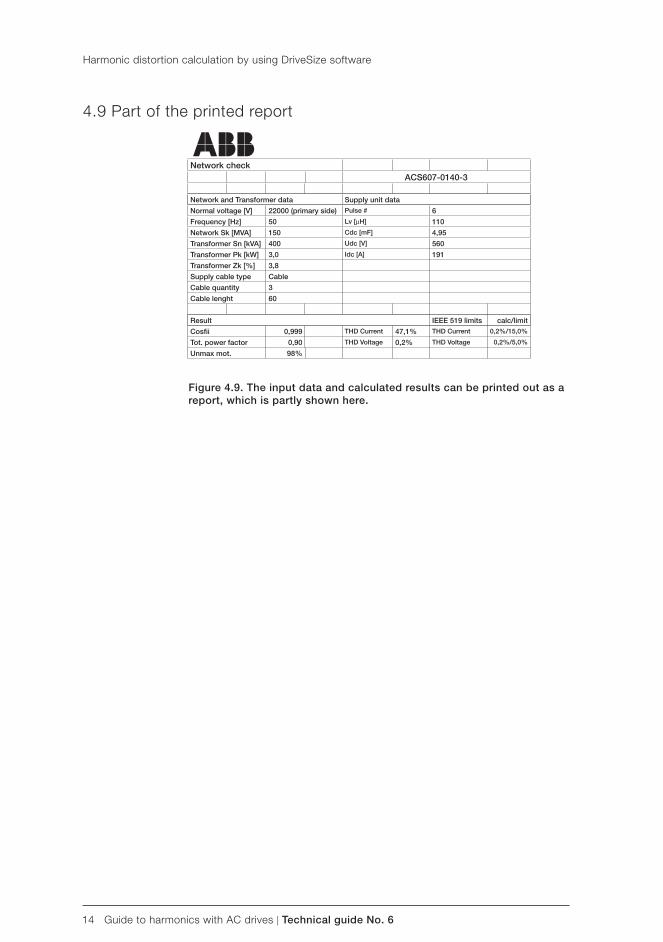
14 Guide to harmonics with AC drives | Technical guide No. 6
Network checkACS607-0140-3
Network and Transformer data Supply unit data
Normal voltage [V] 22000 (primary side) Pulse # 6
Frequency [Hz] 50 Lv [μH] 110
Network Sk [MVA] 150 Cdc [mF] 4,95
Transformer Sn [kVA] 400 Udc [V] 560
Transformer Pk [kW] 3,0 Idc [A] 191
Transformer Zk [%] 3,8
Supply cable type Cable
Cable quantity 3
Cable lenght 60
Result IEEE 519 limits calc/limit
Cosfi i 0,999 THD Current 47,1% THD Current 0,2%/15,0%
Tot. power factor 0,90 THD Voltage 0,2% THD Voltage 0,2%/5,0%
Unmax mot. 98%
Figure 4.9. The input data and calculated results can be printed out as a report, which is partly shown here.
4.9 Part of the printed report
Harmonic distortion calculation by using DriveSize software
Technical guide No. 6 | Guide to harmonics with AC drives 15
6
Chapter 5 - Standards for harmonic limits
The most common international and national standards setting limits on harmonics are described below. Figure 5.1 is shown as an example for harmonic distortion limits.
5.1 EN 61800-3 (IEC 61800-3) Adjustable speed electrical power drive systems
Part 3: EMC product standard including specific test meth-odsThe countries of the European Economic Area (EEA) have agreed on common minimum regulatory requirements in order to ensure the free movement of products within the EEA. The CE marking indicates that the product works in conformity with the directives that are valid for the product. The directives state the principles that must be followed. Standards specify the requirements that must be met. EN 61800-3 is the EMC product standard of ad-justable speed electrical power drive systems (PDS). Meeting the requirements of this standard, is the minimum condition for free trade of power electronics converters inside the EEA.
EN 61800-3 states, that the manufacturer shall provide in the documentation of the PDS, or on request, the current harmonic level, under rated conditions, as a percentage of the rated fun-damental current on the power port. The referenced values shall be calculated for each order at least up to the 25th. The current THD (orders up to and including 40), and its high- frequency component PHD (orders from 14 to 40 inclusive) shall be evalu-ated. For these standard calculations, the PDS shall be assumed to be connected to a PC with Rsc = 250 and with initial voltage distortion less than 1%. The internal impedance of the network shall be assumed to be a pure reactance.
In a low voltage public supply network, the limits and require-ments of IEC 61000-3-2 apply for equipment with rated current ≤ 16 A. The use of the future IEC 61000-3-4 is recommended for equipment with rated current > 16 A. If PDS is used in an industrial installation, a reasonable economical approach, which considers the total installation, shall be used. This approach is based on the agreed power, which the supply can deliver at any time. The method for calculating the harmonics of the total installation is agreed and the limits for either the voltage distor-tion or the total harmonic current emission are agreed on. The compatibility limits given in IEC 61000-2-4 may be used as the limits of voltage distortion.
16 Guide to harmonics with AC drives | Technical guide No. 6
5.2 IEC 61000 -2-2, Electromagnetic compatibility (EMC)
Part 2: Environment - Section 2: Compatibility levels for low frequency conducted disturbances and signalling in public low voltage power supply systemsThis standard sets the compatibility limits for low frequency conducted disturbances and signalling in public low voltage power supply systems. The disturbance phenomena include harmonics, inter-harmonics, voltage fluctuations, voltage dips and short interruptions voltage inbalance and so on. Basically this standard sets the design criteria for the equipment manu-facturer, and amounts to the minimum immunity requirements of the equipment. IEC 61000-2-2 is in line with the limits set in EN 50160 for the quality of the voltage the utility owner must provide at the customer’s supply-terminals.
5.3 IEC 61000-2-4, Electromagnetic compatibility (EMC)
Part 2: Environment - Section 4: Compatibility levels in indus-trial plants for low frequency conducted disturbances IEC 61000-2-4 is similar to IEC 61000-2-2, but it gives compat-ibility levels for industrial and non-public networks. It covers low- voltage networks as well as medium voltage supplies ex-cluding the networks for ships, aircraft, offshore platforms and railways.
5.4 IEC 61000-3-2, Electromagnetic compatibility (EMC)
Part 3: Limits - Section 2: Limits for harmonic current emis-sions (equipment current < 16 A per phase)This standard deals with the harmonic current emission limits of individual equipment connected to public networks. The date of implementation of this standard is January 1, 2001, but there is extensive work going on at the moment to revise the standard before this date. The two main reasons for the revision are the need for the standard to cover also the voltage below 230 V and the difficulties and contradictions in applying the categorisation of the equipment given in the standard.
5.5 IEC 61000-3-4, Electromagnetic compatibility (EMC)
This standard has been published as a Type II Technical report. Work is going on to convert it into a standard. It gives the har-monic current emission limits for individual equipment having a rated current of more than 16 A up to 75 A. It applies to public networks having nominal voltages from 230 V single phase to 600 V three phase.
Standards for harmonic limits
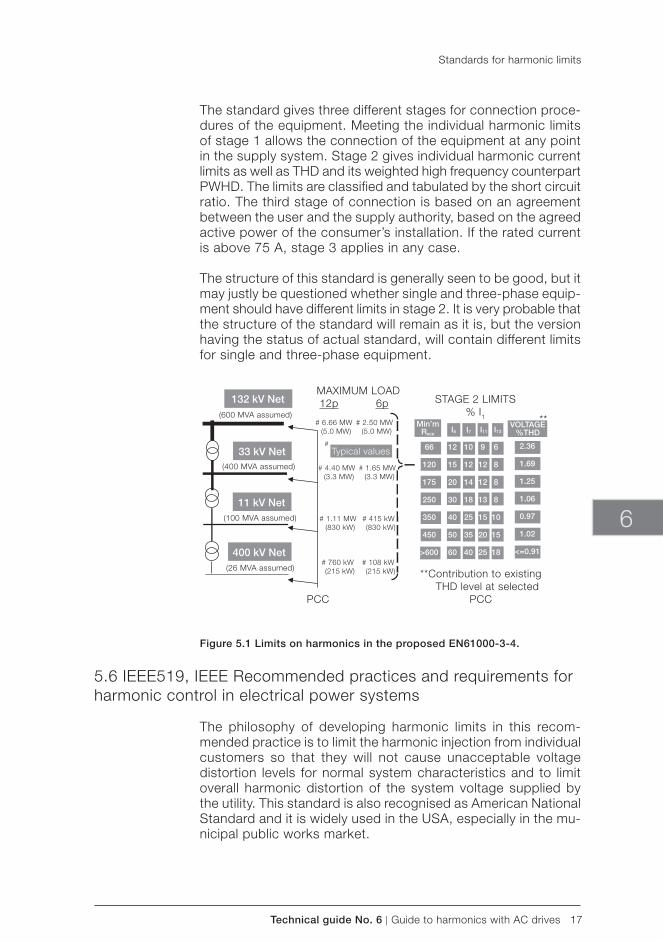
Technical guide No. 6 | Guide to harmonics with AC drives 17
132 kV Net
33 kV Net
11 kV Net
400 kV Net
Typical values
Min’mRsce
66
120
175
250
350
450
>600
12
15
20
30
40
50
60
10
12
14
18
25
35
40
9
12
12
13
15
20
25
6
8
8
8
10
15
18
2.36
1.69
1.25
1.06
0.97
1.02
<=0.91
I5 I7 I11 I13 VOLTAGE
% THD
STAGE 2 LIMITS% I1
MAXIMUM LOAD 12p 6p
# 6.66 MW (5.0 MW)
# 2.50 MW (5.0 MW)
#
# 4.40 MW (3.3 MW)
# 1.65 MW (3.3 MW)
# 1.11 MW (830 kW)
# 415 kW (830 kW)
# 760 kW (215 kW)
# 108 kW (215 kW)
PCC
**Contribution to existing THD level at selected
PCC
(26 MVA assumed)
(100 MVA assumed)
(400 MVA assumed)
(600 MVA assumed) **
6
The standard gives three different stages for connection proce-dures of the equipment. Meeting the individual harmonic limits of stage 1 allows the connection of the equipment at any point in the supply system. Stage 2 gives individual harmonic current limits as well as THD and its weighted high frequency counterpart PWHD. The limits are classified and tabulated by the short circuit ratio. The third stage of connection is based on an agreement between the user and the supply authority, based on the agreed active power of the consumer’s installation. If the rated current is above 75 A, stage 3 applies in any case.
The structure of this standard is generally seen to be good, but it may justly be questioned whether single and three-phase equip-ment should have different limits in stage 2. It is very probable that the structure of the standard will remain as it is, but the version having the status of actual standard, will contain different limits for single and three-phase equipment.
Figure 5.1 Limits on harmonics in the proposed EN61000-3-4.
5.6 IEEE519, IEEE Recommended practices and requirements for harmonic control in electrical power systems
The philosophy of developing harmonic limits in this recom-mended practice is to limit the harmonic injection from individual customers so that they will not cause unacceptable voltage distortion levels for normal system characteristics and to limit overall harmonic distortion of the system voltage supplied by the utility. This standard is also recognised as American National Standard and it is widely used in the USA, especially in the mu-nicipal public works market.
Standards for harmonic limits
18 Guide to harmonics with AC drives | Technical guide No. 6
The standard does not give limits for individual equipment, but for individual customers. The customers are categorised by the ratio of available short circuit current (Isc) to their maximum demand load current (IL) at the point of common coupling. The total demand load current is the sum of both linear and non-linear loads. Within an industrial plant, the PCC is clearly defined as the point between the non-linear load and other loads.
The allowed individual harmonic currents and total harmonic dis-tortion are tabulated by the ratio of available short circuit current to the total demand load current (Isc/IL) at the point of common coupling. The limits are as a percentage of IL for all odd and even harmonics from 2 to infinity. Total harmonic distortion is called total demand distortion and also it should be calculated up to infinity. Many authors limit the calculation of both the individual components and TDD to 50.
The table 10.3 of the standard is sometimes misinterpreted to give limits for the harmonic emissions of a single apparatus by using Rsc of the equipment instead of Isc/IL of the whole instal-lation. The limits of the table should not be used this way, since the ratio of the short circuit current to the total demand load current of an installation should always be used.
Standards for harmonic limits
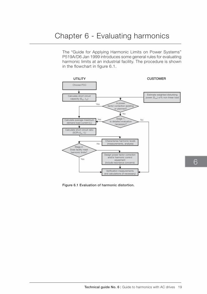
Technical guide No. 6 | Guide to harmonics with AC drives 19
Verification measurementsand calculations (if necessary)
UTILITY
Calculate average maximum demand load current (IL)
Choose PCC
Calculate short circuit capacity (SSC, ISC)
Calculate short circuit ratio (SCR=(ISC /IL)
Yes
Yes
No
Yes
No
Is power factor correction existing
or planned?
Stage 1: Is detailed evaluation
necessary?
No
Estimate weighted disturbing power (SDW) or% non-linear load
Stage 2: Does facility meet harmonic limits?
Characterise harmonic levels(measurements, analysis)
Design power factor correctionand/or harmonic control
equipment(include resonance concerns)
CUSTOMER
6
Chapter 6 - Evaluating harmonics
The “Guide for Applying Harmonic Limits on Power Systems” P519A/D6 Jan 1999 introduces some general rules for evaluating harmonic limits at an industrial facility. The procedure is shown in the flowchart in figure 6.1.
Figure 6.1 Evaluation of harmonic distortion.
20 Guide to harmonics with AC drives | Technical guide No. 6
Line
Transformer
AC drive
Load
Short circuit power
Rated power andimpedance
Type of rectifi er
DIODE, THYRISTOR; INVERTER:
MVA
MVA
%
mH
PWM;CSI
kW
%
6-p, 12-p, 24-p
Reactor inductance
Type of inverter
Rated power andload
Inverter
Motor
Alternative
7.1 Factors in the AC drive having an effect on harmonics
Harmonics reduction can be done either by structural modifi-cations in the drive system or by using external filtering. The structural modifications can be to strengthen the supply, to use 12 or more pulse drive, to use a controlled rectifier or to improve the internal filtering in the drive.
Figure 7.1 shows the factors in the AC drive system which have some influence on harmonics. The current harmonics depend on the drive construction and the voltage harmonics are the current harmonics multiplied by the supply impedances.
Chapter 7 - How to reduce harmonics by structural modifications in the AC drive system
Figure 7.1 Drive system features affecting harmonics.
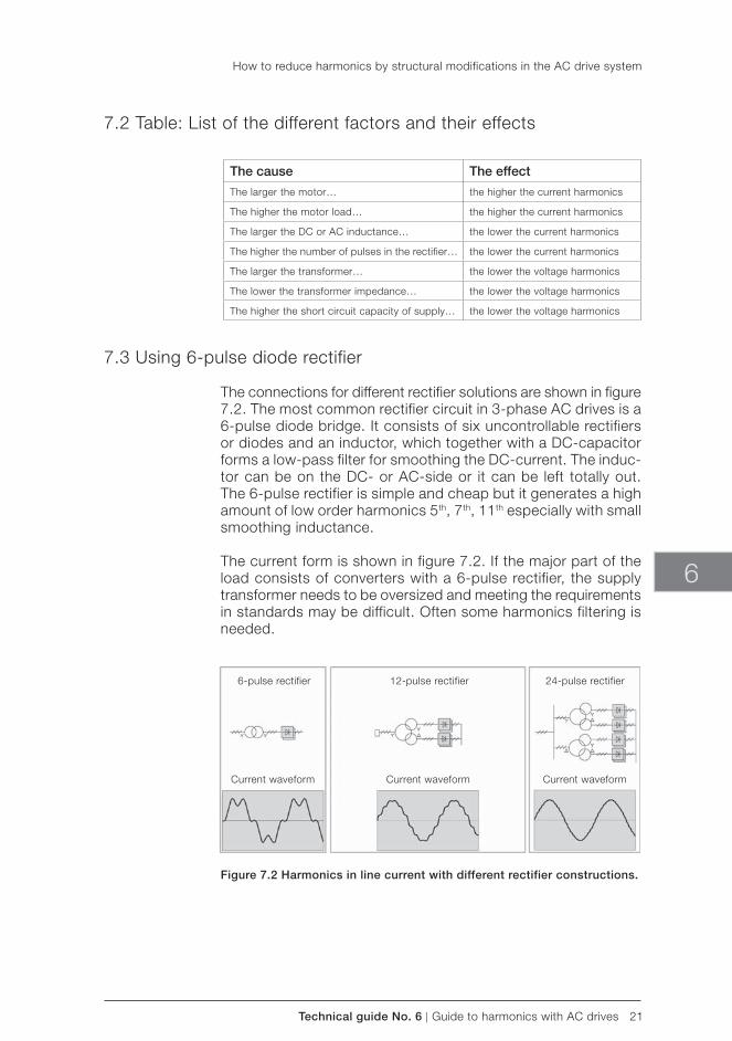
Technical guide No. 6 | Guide to harmonics with AC drives 21
The cause The effect
The larger the motor… the higher the current harmonics
The higher the motor load… the higher the current harmonics
The larger the DC or AC inductance… the lower the current harmonics
The higher the number of pulses in the rectifier… the lower the current harmonics
The larger the transformer… the lower the voltage harmonics
The lower the transformer impedance… the lower the voltage harmonics
The higher the short circuit capacity of supply… the lower the voltage harmonics
6-pulse rectifier 12-pulse rectifier 24-pulse rectifier
Current waveform Current waveform Current waveform
6
7.2 Table: List of the different factors and their effects
7.3 Using 6-pulse diode rectifier
The connections for different rectifier solutions are shown in figure 7.2. The most common rectifier circuit in 3-phase AC drives is a 6-pulse diode bridge. It consists of six uncontrollable rectifiers or diodes and an inductor, which together with a DC-capacitor forms a low-pass filter for smoothing the DC-current. The induc-tor can be on the DC- or AC-side or it can be left totally out. The 6-pulse rectifier is simple and cheap but it generates a high amount of low order harmonics 5th, 7th, 11th especially with small smoothing inductance.
The current form is shown in figure 7.2. If the major part of the load consists of converters with a 6-pulse rectifier, the supply transformer needs to be oversized and meeting the requirements in standards may be difficult. Often some harmonics filtering is needed.
Figure 7.2 Harmonics in line current with different rectifier constructions.
How to reduce harmonics by structural modifications in the AC drive system
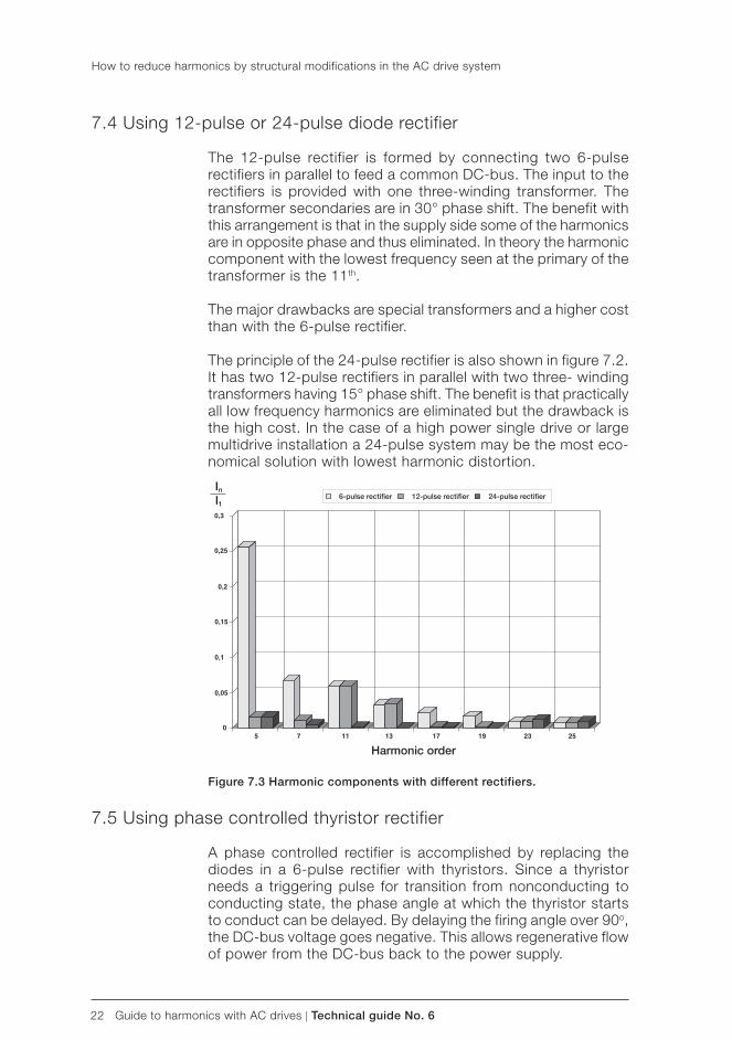
22 Guide to harmonics with AC drives | Technical guide No. 6
6-pulse rectifi er 12-pulse rectifi er 24-pulse rectifi er
Harmonic order
In
I1
7.4 Using 12-pulse or 24-pulse diode rectifier
The 12-pulse rectifier is formed by connecting two 6-pulse rectifiers in parallel to feed a common DC-bus. The input to the rectifiers is provided with one three-winding transformer. The transformer secondaries are in 30° phase shift. The benefit with this arrangement is that in the supply side some of the harmonics are in opposite phase and thus eliminated. In theory the harmonic component with the lowest frequency seen at the primary of the transformer is the 11th.
The major drawbacks are special transformers and a higher cost than with the 6-pulse rectifier.
The principle of the 24-pulse rectifier is also shown in figure 7.2. It has two 12-pulse rectifiers in parallel with two three- winding transformers having 15° phase shift. The benefit is that practically all low frequency harmonics are eliminated but the drawback is the high cost. In the case of a high power single drive or large multidrive installation a 24-pulse system may be the most eco-nomical solution with lowest harmonic distortion.
Figure 7.3 Harmonic components with different rectifiers.
7.5 Using phase controlled thyristor rectifier
A phase controlled rectifier is accomplished by replacing the diodes in a 6-pulse rectifier with thyristors. Since a thyristor needs a triggering pulse for transition from nonconducting to conducting state, the phase angle at which the thyristor starts to conduct can be delayed. By delaying the firing angle over 90o, the DC-bus voltage goes negative. This allows regenerative flow of power from the DC-bus back to the power supply.
How to reduce harmonics by structural modifications in the AC drive system
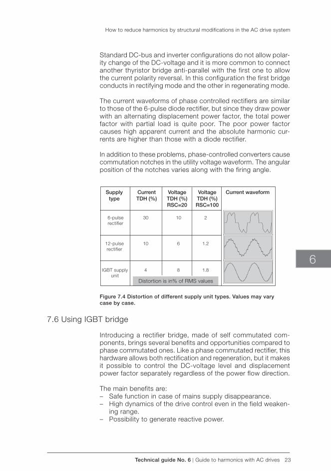
Technical guide No. 6 | Guide to harmonics with AC drives 23
Supplytype
6-pulse rectifier
12-pulse rectifier
IGBT supply unit
CurrentTDH (%)
30
10
4
VoltageTDH (%)RSC=20
10
6
8
VoltageTDH (%)RSC=100
2
1.2
1.8
Current waveform
Distortion is in% of RMS values
6
Standard DC-bus and inverter configurations do not allow polar-ity change of the DC- voltage and it is more common to connect another thyristor bridge anti-parallel with the first one to allow the current polarity reversal. In this configuration the first bridge conducts in rectifying mode and the other in regenerating mode.
The current waveforms of phase controlled rectifiers are similar to those of the 6-pulse diode rectifier, but since they draw power with an alternating displacement power factor, the total power factor with partial load is quite poor. The poor power factor causes high apparent current and the absolute harmonic cur-rents are higher than those with a diode rectifier.
In addition to these problems, phase-controlled converters cause commutation notches in the utility voltage waveform. The angular position of the notches varies along with the firing angle.
Figure 7.4 Distortion of different supply unit types. Values may varycase by case.
7.6 Using IGBT bridge
Introducing a rectifier bridge, made of self commutated com-ponents, brings several benefits and opportunities compared to phase commutated ones. Like a phase commutated rectifier, this hardware allows both rectification and regeneration, but it makes it possible to control the DC- voltage level and displacement power factor separately regardless of the power flow direction.
The main benefits are: – Safe function in case of mains supply disappearance. – High dynamics of the drive control even in the field weaken-
ing range. – Possibility to generate reactive power.
How to reduce harmonics by structural modifications in the AC drive system
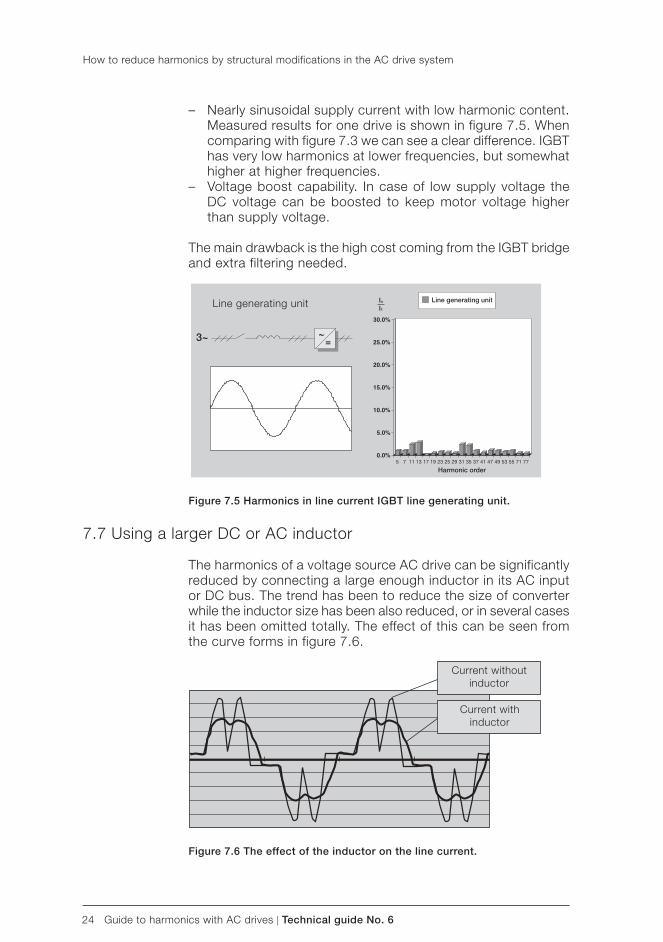
24 Guide to harmonics with AC drives | Technical guide No. 6
Line generating unit
3~
Line generating unit
Harmonic order
In
I1
Current without inductor
Current with inductor
– Nearly sinusoidal supply current with low harmonic content. Measured results for one drive is shown in figure 7.5. When comparing with figure 7.3 we can see a clear difference. IGBT has very low harmonics at lower frequencies, but somewhat higher at higher frequencies.
– Voltage boost capability. In case of low supply voltage the DC voltage can be boosted to keep motor voltage higher than supply voltage.
The main drawback is the high cost coming from the IGBT bridge and extra filtering needed.
Figure 7.5 Harmonics in line current IGBT line generating unit.
7.7 Using a larger DC or AC inductor
The harmonics of a voltage source AC drive can be significantly reduced by connecting a large enough inductor in its AC input or DC bus. The trend has been to reduce the size of converter while the inductor size has been also reduced, or in several cases it has been omitted totally. The effect of this can be seen from the curve forms in figure 7.6.
Figure 7.6 The effect of the inductor on the line current.
How to reduce harmonics by structural modifications in the AC drive system
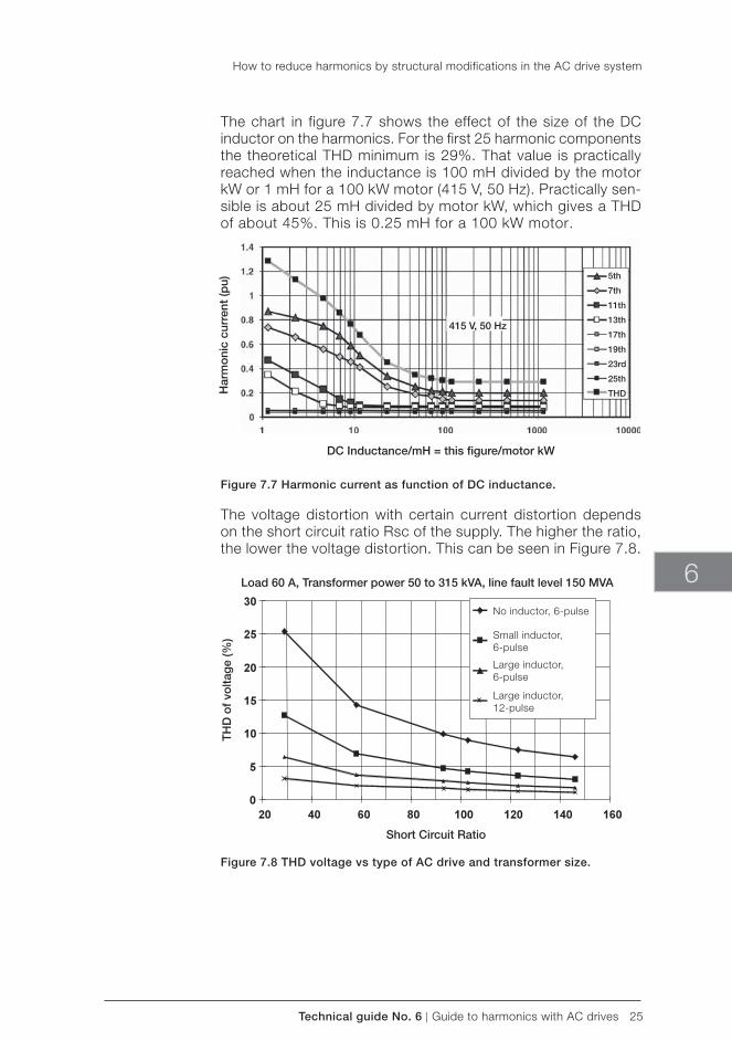
Technical guide No. 6 | Guide to harmonics with AC drives 25
415 V, 50 Hz
5th
7th
11th
13th
17th
19th
23rd
25th
THD
DC Inductance/mH = this fi gure/motor kW
Har
mo
nic
curr
ent
(pu)
Load 60 A, Transformer power 50 to 315 kVA, line fault level 150 MVA
TH
D o
f vo
ltag
e (%
)
Short Circuit Ratio
No inductor, 6-pulse
Small inductor,6-pulse
Large inductor, 6-pulse
Large inductor, 12-pulse
6
The chart in figure 7.7 shows the effect of the size of the DC inductor on the harmonics. For the first 25 harmonic components the theoretical THD minimum is 29%. That value is practically reached when the inductance is 100 mH divided by the motor kW or 1 mH for a 100 kW motor (415 V, 50 Hz). Practically sen-sible is about 25 mH divided by motor kW, which gives a THD of about 45%. This is 0.25 mH for a 100 kW motor.
Figure 7.7 Harmonic current as function of DC inductance.
The voltage distortion with certain current distortion depends on the short circuit ratio Rsc of the supply. The higher the ratio, the lower the voltage distortion. This can be seen in Figure 7.8.
Figure 7.8 THD voltage vs type of AC drive and transformer size.
How to reduce harmonics by structural modifications in the AC drive system
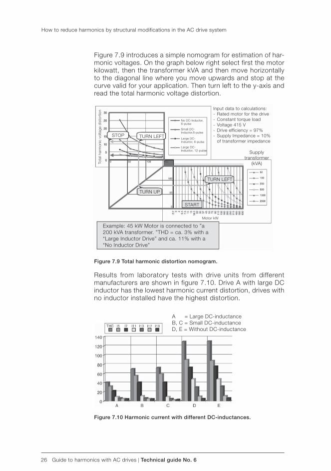
26 Guide to harmonics with AC drives | Technical guide No. 6
A = Large DC- inductanceB, C = Small DC- inductanceD, E = Without DC- inductance
Example: 45 kW Motor is connected to ”a 200 kVA transformer. ”THD = ca. 3% with a “Large Inductor Drive” and ca. 11% with a “No Inductor Drive”
Tota
l har
mon
ic v
olta
ge d
isto
rtio
n Input data to calculations:- Rated motor for the drive- Constant torque load- Voltage 415 V- Drive efficiency = 97%- Supply Impedance = 10% of transformer impedance
Supply transformer
(kVA)
STOP TURN LEFT
START
TURN LEFT
TURN UP
Motor kW
No DC-Inductor,6-pulse
Small DC-Inductor,6-pulse
Large DC-Inductor, 6-pulse
Large DC-Inductor, 12-pulse
Figure 7.9 introduces a simple nomogram for estimation of har-monic voltages. On the graph below right select first the motor kilowatt, then the transformer kVA and then move horizontally to the diagonal line where you move upwards and stop at the curve valid for your application. Then turn left to the y-axis and read the total harmonic voltage distortion.
Figure 7.9 Total harmonic distortion nomogram.
Results from laboratory tests with drive units from different manufacturers are shown in figure 7.10. Drive A with large DC inductor has the lowest harmonic current distortion, drives with no inductor installed have the highest distortion.
Figure 7.10 Harmonic current with different DC-inductances.
How to reduce harmonics by structural modifications in the AC drive system
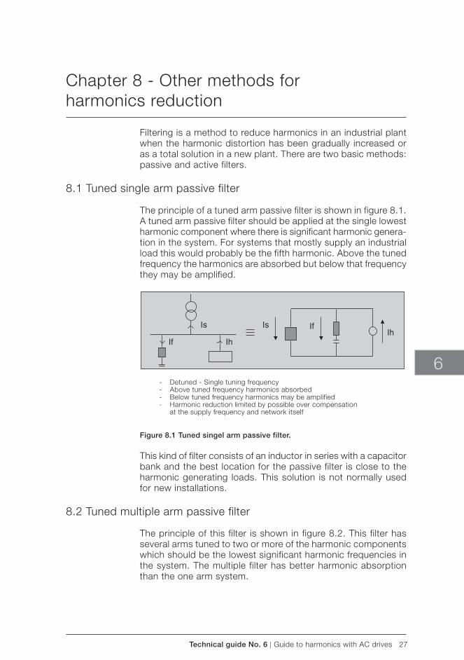
Technical guide No. 6 | Guide to harmonics with AC drives 27
- Detuned - Single tuning frequency- Above tuned frequency harmonics absorbed- Below tuned frequency harmonics may be amplified- Harmonic reduction limited by possible over compensation at the supply frequency and network itself
6
Chapter 8 - Other methods for harmonics reduction
Filtering is a method to reduce harmonics in an industrial plant when the harmonic distortion has been gradually increased or as a total solution in a new plant. There are two basic methods: passive and active filters.
8.1 Tuned single arm passive filter
The principle of a tuned arm passive filter is shown in figure 8.1. A tuned arm passive filter should be applied at the single lowest harmonic component where there is significant harmonic genera-tion in the system. For systems that mostly supply an industrial load this would probably be the fifth harmonic. Above the tuned frequency the harmonics are absorbed but below that frequency they may be amplified.
Figure 8.1 Tuned singel arm passive filter.
This kind of filter consists of an inductor in series with a capacitor bank and the best location for the passive filter is close to the harmonic generating loads. This solution is not normally used for new installations.
8.2 Tuned multiple arm passive filter
The principle of this filter is shown in figure 8.2. This filter has several arms tuned to two or more of the harmonic components which should be the lowest significant harmonic frequencies in the system. The multiple filter has better harmonic absorption than the one arm system.
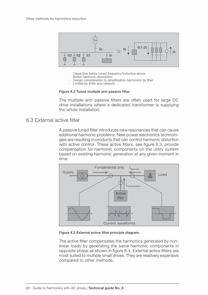
28 Guide to harmonics with AC drives | Technical guide No. 6
Fundamental only idistortion
icompensation
Load
Activefilter
Current waveforms
Supply
- Capacitive below tuned frequency/Inductive above- Better harmonic absorption- Design consideration to amplification harmonics by filter- Limited by KVAr and network
Figure 8.2 Tuned multiple arm passive filter.
The multiple arm passive filters are often used for large DC drive installations where a dedicated transformer is supplying the whole installation.
8.3 External active filter
A passive tuned filter introduces new resonances that can cause additional harmonic problems. New power electronics technolo-gies are resulting in products that can control harmonic distortion with active control. These active filters, see figure 8.3, provide compensation for harmonic components on the utility system based on existing harmonic generation at any given moment in time.
Figure 8.3 External active filter principle diagram.
The active filter compensates the harmonics generated by non-linear loads by generating the same harmonic components in opposite phase as shown in figure 8.4. External active filters are most suited to multiple small drives. They are relatively expensive compared to other methods.
Other methods for harmonics reduction
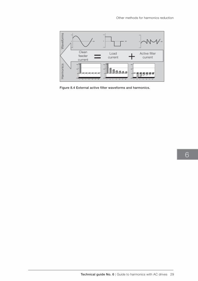
Technical guide No. 6 | Guide to harmonics with AC drives 29
Cleanfeedercurrent
Loadcurrent
Active filtercurrent
Har
mon
ics
Wav
efor
ms
6
Figure 8.4 External active filter waveforms and harmonics.
Other methods for harmonics reduction
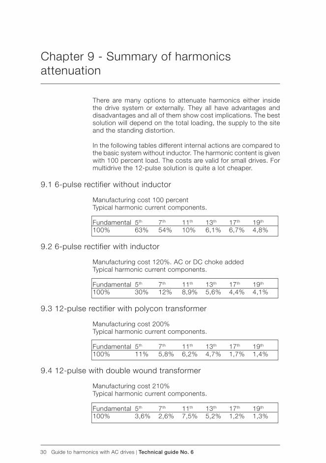
30 Guide to harmonics with AC drives | Technical guide No. 6
There are many options to attenuate harmonics either inside the drive system or externally. They all have advantages and disadvantages and all of them show cost implications. The best solution will depend on the total loading, the supply to the site and the standing distortion.
In the following tables different internal actions are compared to the basic system without inductor. The harmonic content is given with 100 percent load. The costs are valid for small drives. For multidrive the 12-pulse solution is quite a lot cheaper.
9.1 6-pulse rectifier without inductor
Manufacturing cost 100 percentTypical harmonic current components.
Fundamental 5th 7th 11th 13th 17th 19th 100% 63% 54% 10% 6,1% 6,7% 4,8%
9.2 6-pulse rectifier with inductor
Manufacturing cost 120%. AC or DC choke addedTypical harmonic current components.
Fundamental 5th 7th 11th 13th 17th 19th 100% 30% 12% 8,9% 5,6% 4,4% 4,1%
9.3 12-pulse rectifier with polycon transformer
Manufacturing cost 200%Typical harmonic current components.
Fundamental 5th 7th 11th 13th 17th 19th 100% 11% 5,8% 6,2% 4,7% 1,7% 1,4%
9.4 12-pulse with double wound transformer
Manufacturing cost 210%Typical harmonic current components.
Fundamental 5th 7th 11th 13th 17th 19th 100% 3,6% 2,6% 7,5% 5,2% 1,2% 1,3%
Chapter 9 - Summary of harmonics attenuation
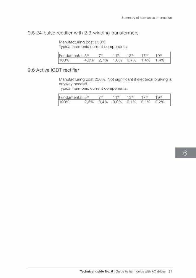
Technical guide No. 6 | Guide to harmonics with AC drives 31
6
9.5 24-pulse rectifier with 2 3-winding transformers
Manufacturing cost 250%Typical harmonic current components.
Fundamental 5th 7th 11th 13th 17th 19th 100% 4,0% 2,7% 1,0% 0,7% 1,4% 1,4%
9.6 Active IGBT rectifier
Manufacturing cost 250%. Not significant if electrical braking is anyway needed.Typical harmonic current components.
Fundamental 5th 7th 11th 13th 17th 19th 100% 2,6% 3,4% 3,0% 0,1% 2,1% 2,2%
Summary of harmonics attenuation
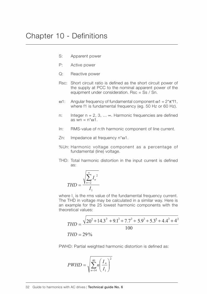
32 Guide to harmonics with AC drives | Technical guide No. 6
Chapter 10 - Definitions
S: Apparent power
P: Active power
Q: Reactive power
Rsc: Short circuit ratio is defined as the short circuit power of the supply at PCC to the nominal apparent power of the equipment under consideration. Rsc = Ss / Sn.
ω1: Angular frequency of fundamental component ω1 = 2*π*f1, where f1 is fundamental frequency (eg. 50 Hz or 60 Hz).
n: Integer n = 2, 3, ... ∞. Harmonic frequencies are defined as wn = n*ω1.
In: RMS-value of n:th harmonic component of line current.
Zn: Impedance at frequency n*ω1.
%Un: Harmonic voltage component as a percentage of fundamental (line) voltage.
THD: Total harmonic distortion in the input current is defined as:
where I1 is the rms value of the fundamental frequency current. The THD in voltage may be calculated in a similar way. Here is an example for the 25 lowest harmonic components with the theoretical values:
PWHD: Partial weighted harmonic distortion is defined as:

Technical guide No. 6 | Guide to harmonics with AC drives 33
6
PCC: Point of common coupling is defined in this text as such a point of utility supply which may be common to the equipment in question and other equipment. There are several definitions of PCC in different standards and even more interpretations of these definitions in literature. The definit ion chosen here is seen as technically most sound.
PF: Power factor is defined as PF = P/S (power / volt-ampere) = I1 / Is * DPF (With sinusoidal current PF equals to DPF).
DPF: Displacement power factor is defined as cosφ1, where φ1 is the phase angle between the fundamental frequency current drawn by the equipment and the supply voltage fundamental frequency component.
Definitions
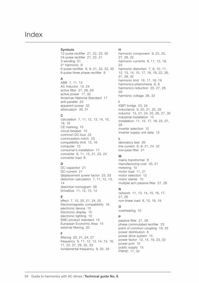
34 Guide to harmonics with AC drives | Technical guide No. 6
Index
Symbols12-pulse rectifier 21, 22, 23, 3024-pulse rectifier 21, 22, 313-winding 315th harmonic 96-pulse rectifier 8, 9, 21, 22, 23, 306-pulse three phase rectifier 9
AABB 7, 11, 13AC inductor 13, 24active filter 27, 28, 29active power 17, 32American National Standard 17anti-parallel 23apparent power 32attenuation 30, 31
Ccalculation 7, 11, 12, 13, 14, 15, 18, 19CE marking 15circuit breaker 10common DC-bus 22commutation notch 23compatibility limit 15, 16computer 10consumer’s installation 17converter 8, 11, 15, 21, 23, 24converter load 8
DDC-capacitor 21DC-current 21displacement power factor 23, 33distortion calculation 7, 11, 12, 13, 14distortion nomogram 26DriveSize 11, 12, 13, 14
Eeffect 7, 10, 20, 21, 24, 25Electromagnetic compatibility 16electronic device 10Electronic display 10electronic lighting 10EMC product standard 15European Economic Area 15external filtering 20
Ffiltering 20, 21, 24, 27frequency 9, 11, 12, 13, 14, 15, 16, 17, 22, 27, 28, 32, 33fundamental frequency 9, 32, 33
Hharmonic component 9, 22, 25, 27, 28, 32harmonic currents 8, 11, 13, 18, 23harmonic distortion 7, 8, 10, 11, 12, 13, 14, 15, 17, 18, 19, 22, 26, 27, 28, 32harmonic limit 16, 17, 18, 19harmonics phenomena 8, 9harmonics reduction 20, 27, 28, 29harmonic voltage 26, 32
IIGBT bridge 23, 24inductance 9, 20, 21, 25, 26inductor 13, 21, 24, 25, 26, 27, 30industrial installation 15installation 11, 15, 17, 18, 22, 27, 28inverter selection 12Inverter supply unit data 12
Llaboratory test 26line current 8, 9, 21, 24, 32low-pass filter 21
Mmains transformer 8manufacturing cost 30, 31metering 10motor load 11, 21motor selection 12motor starter 10multiple arm passive filter 27, 28
Nnetwork 11, 13, 14, 15, 16, 17, 27, 28non-linear load 8, 10, 18, 19
Ooverheating 10
Ppassive filter 27, 28phase commutated rectifier 23point of common coupling 18, 33power distribution 8power drive system 15power factor 12, 14, 19, 23, 33power port 15public supply 15PWHD 17, 32

Technical guide No. 6 | Guide to harmonics with AC drives 35
6
Rreactive power 23, 32rectifier 8, 9, 20, 21, 22, 23, 30, 31rectifying mode 23regenerating mode 23report 14, 16
Sshort circuit power 20, 32short circuit ratio 17, 19, 25, 32source 7, 10, 11, 24source impedance 11standard 13, 15, 16, 17, 18, 21, 23, 33structural modification 20, 21, 22, 23, 24, 25, 26supply authority 17supply cable 13, 14supply transformer 21supply voltage 8, 24, 33
TTDD 18THD 13, 14, 15, 17, 25, 32three-winding transformer 22thyristor 13, 20, 22, 23total demand distortion 18total harmonic distortion 18, 26, 32transformer 8, 10, 11, 13, 14, 20, 21, 22, 25, 26, 28, 30, 31tuned arm passive filter 27
Vvariable speed drives 10voltage 8, 11, 12, 13, 14, 15, 16, 17, 20, 21, 22, 23, 24, 25, 26, 32, 33voltage boost 23, 24
Index

36 Guide to harmonics with AC drives | Technical guide No. 6

3AFE
6429
2714
RE
V D
EN
11.
2.20
13 #
1667
9
Contact us
For more information please contact your local ABB representative or visit:
www.abb.com/driveswww.abb.com/drivespartners
© Copyright 2013 ABB. All rights reserved. Specifications subject to change without notice.

Technical guide No. 7Dimensioning of a drive system
ABB drives

2 Dimensioning of a drive system | Technical guide No. 7

Technical guide No. 7 | Dimensioning of a drive system 3
© Copyright 2011 ABB. All rights reserved.
Specifications subject to change without notice.
3AFE64362569 REV C EN 28.4.2011
Technical guide No. 7Dimensioning of a drive system
7

4 Dimensioning of a drive system | Technical guide No. 7
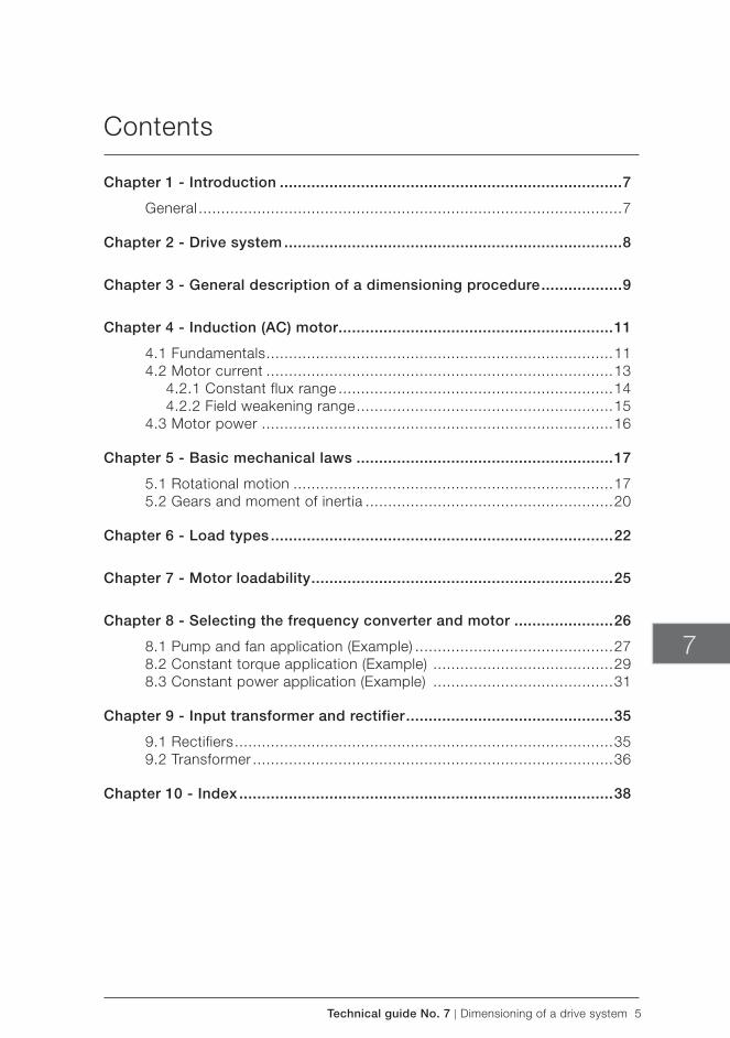
Technical guide No. 7 | Dimensioning of a drive system 5
7
Contents
Chapter 1 - Introduction ............................................................................7
General ..............................................................................................7
Chapter 2 - Drive system ...........................................................................8
Chapter 3 - General description of a dimensioning procedure ..................9
Chapter 4 - Induction (AC) motor.............................................................11
4.1 Fundamentals .............................................................................114.2 Motor current .............................................................................13
4.2.1 Constant flux range .............................................................144.2.2 Field weakening range .........................................................15
4.3 Motor power ..............................................................................16
Chapter 5 - Basic mechanical laws .........................................................17
5.1 Rotational motion .......................................................................175.2 Gears and moment of inertia .......................................................20
Chapter 6 - Load types ............................................................................22
Chapter 7 - Motor loadability ...................................................................25
Chapter 8 - Selecting the frequency converter and motor ......................26
8.1 Pump and fan application (Example) ............................................278.2 Constant torque application (Example) ........................................298.3 Constant power application (Example) ........................................31
Chapter 9 - Input transformer and rectifier ..............................................35
9.1 Rectifiers ....................................................................................359.2 Transformer ................................................................................36
Chapter 10 - Index ...................................................................................38

6 Dimensioning of a drive system | Technical guide No. 7

Technical guide No. 7 | Dimensioning of a drive system 7
7
Chapter 1 - Introduction
General
Dimensioning of a drive system is a task where all factors have to be considered carefully. Dimensioning requires knowledge of the whole system including electric supply, driven machine, environmental conditions, motors and drives, etc. Time spent at the dimensioning phase can mean considerable cost savings.
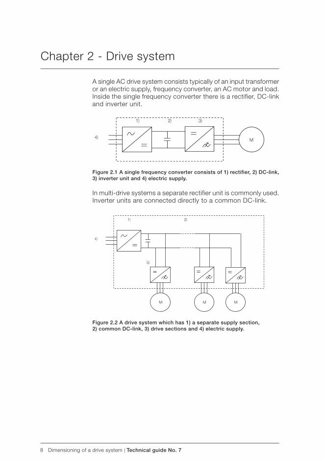
8 Dimensioning of a drive system | Technical guide No. 7
Chapter 2 - Drive system
A single AC drive system consists typically of an input transformer or an electric supply, frequency converter, an AC motor and load. Inside the single frequency converter there is a rectifier, DC-link and inverter unit.
Figure 2.1 A single frequency converter consists of 1) rectifier, 2) DC-link,3) inverter unit and 4) electric supply.
In multi-drive systems a separate rectifier unit is commonly used. Inverter units are connected directly to a common DC-link.
Figure 2.2 A drive system which has 1) a separate supply section,2) common DC-link, 3) drive sections and 4) electric supply.
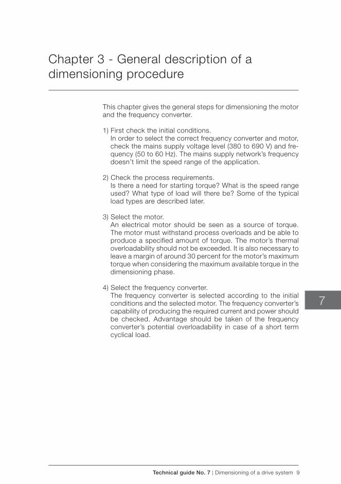
Technical guide No. 7 | Dimensioning of a drive system 9
7
This chapter gives the general steps for dimensioning the motor and the frequency converter.
1) First check the initial conditions. In order to select the correct frequency converter and motor,
check the mains supply voltage level (380 to 690 V) and fre-quency (50 to 60 Hz). The mains supply network’s frequency doesn’t limit the speed range of the application.
2) Check the process requirements. Is there a need for starting torque? What is the speed range
used? What type of load will there be? Some of the typical load types are described later.
3) Select the motor. An electrical motor should be seen as a source of torque.
The motor must withstand process overloads and be able to produce a specified amount of torque. The motor’s thermal overloadability should not be exceeded. It is also necessary to leave a margin of around 30 percent for the motor’s maximum torque when considering the maximum available torque in the dimensioning phase.
4) Select the frequency converter. The frequency converter is selected according to the initial
conditions and the selected motor. The frequency converter’s capability of producing the required current and power should be checked. Advantage should be taken of the frequency converter’s potential overloadability in case of a short term cyclical load.
Chapter 3 - General description of a dimensioning procedure
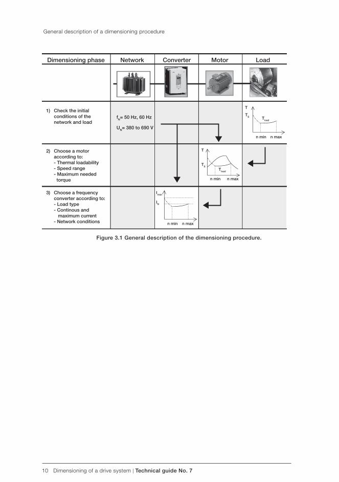
10 Dimensioning of a drive system | Technical guide No. 7
Dimensioning phase Network Converter Motor Load
1) Check the initial conditions of the network and load
2) Choose a motor according to: - Thermal loadability - Speed range - Maximum needed torque
3) Choose a frequency converter according to: - Load type - Continous and maximum current - Network conditions
fN= 50 Hz, 60 Hz
UN= 380 to 690 V
Tload
T
n min n max
Tload
T
TS
n min n max
Imax
IN
n min n max
TS
General description of a dimensioning procedure
Figure 3.1 General description of the dimensioning procedure.
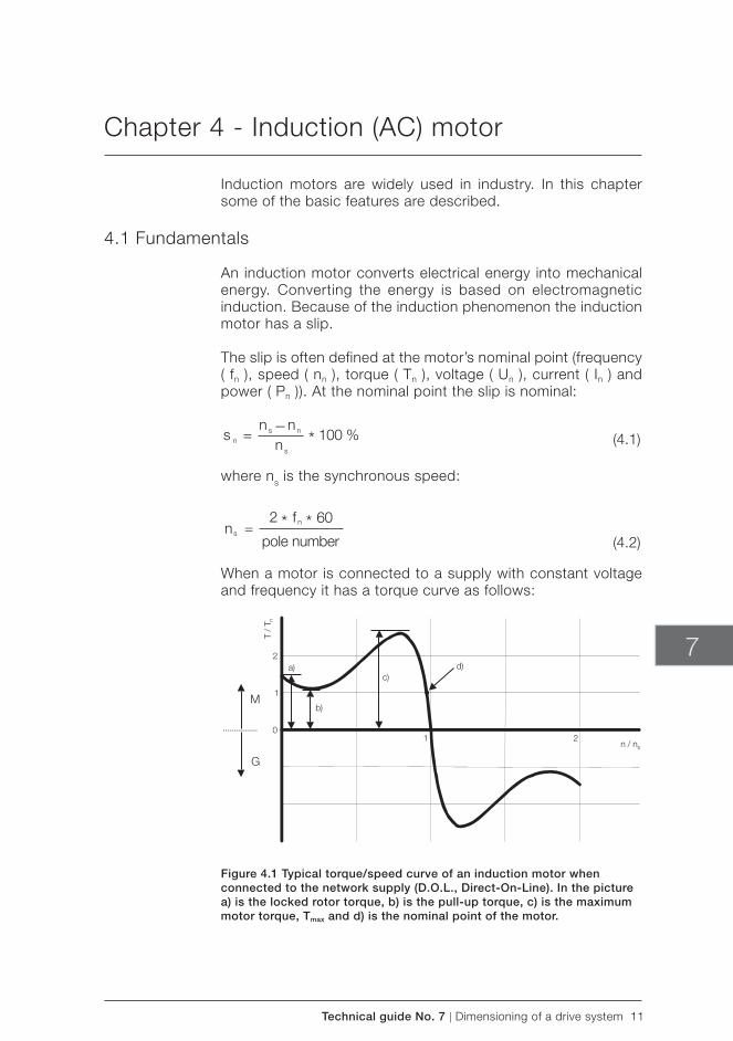
Technical guide No. 7 | Dimensioning of a drive system 11
7
Chapter 4 - Induction (AC) motor
Induction motors are widely used in industry. In this chapter some of the basic features are described.
4.1 Fundamentals
An induction motor converts electrical energy into mechanical energy. Converting the energy is based on electromagnetic induction. Because of the induction phenomenon the induction motor has a slip.
The slip is often defined at the motor’s nominal point ( frequency ( fn ), speed ( nn ), torque ( Tn ), voltage ( Un ), current ( In ) and power ( Pn )). At the nominal point the slip is nominal:
where ns is the synchronous speed:
When a motor is connected to a supply with constant voltage and frequency it has a torque curve as follows:
Figure 4.1 Typical torque/ speed curve of an induction motor when connected to the network supply (D.O.L., Direct-On-Line). In the picture a) is the locked rotor torque, b) is the pull-up torque, c) is the maximum motor torque, Tmax and d) is the nominal point of the motor.
(4.1)
(4.2)
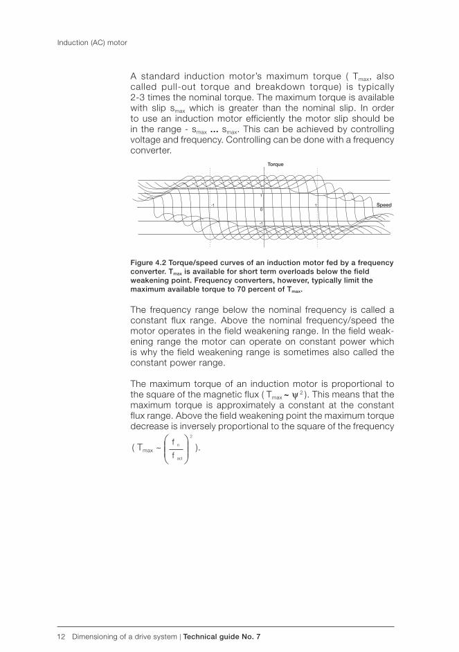
12 Dimensioning of a drive system | Technical guide No. 7
Torque
Speed
A standard induction motor’s maximum torque ( Tmax, also called pull-out torque and breakdown torque) is typically2-3 times the nominal torque. The maximum torque is available with slip smax which is greater than the nominal slip. In order to use an induction motor efficiently the motor slip should be in the range - smax ... smax. This can be achieved by controlling voltage and frequency. Controlling can be done with a frequency converter.
Figure 4.2 Torque/ speed curves of an induction motor fed by a frequency converter. Tmax is available for short term overloads below the field weakening point. Frequency converters, however, typically limit the maximum available torque to 70 percent of Tmax.
The frequency range below the nominal frequency is called a constant flux range. Above the nominal frequency/ speed the motor operates in the field weakening range. In the field weak-ening range the motor can operate on constant power which is why the field weakening range is sometimes also called the constant power range.
The maximum torque of an induction motor is proportional to the square of the magnetic flux ( Tmax ~ ψ 2 ). This means that the maximum torque is approximately a constant at the constant flux range. Above the field weakening point the maximum torque decrease is inversely proportional to the square of the frequency
( Tmax ~ ).
Induction (AC) motor
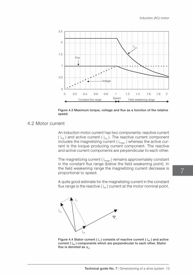
Technical guide No. 7 | Dimensioning of a drive system 13
Constant fl ux range Speed Field weekening range
Flux
Tmax
Voltage
7
Figure 4.3 Maximum torque, voltage and flux as a function of the relative speed.
4.2 Motor current
An induction motor current has two components: reactive current ( isd ) and active current ( isq ). The reactive current component includes the magnetizing current ( imagn ) whereas the active cur-rent is the torque producing current component. The reactive and active current components are perpendicular to each other.
The magnetizing current ( imagn ) remains approximately constant in the constant flux range (below the field weakening point). In the field weakening range the magnetizing current decrease is proportional to speed.
A quite good estimate for the magnetizing current in the constant flux range is the reactive ( isd ) current at the motor nominal point.
Figure 4.4 Stator current ( is ) consists of reactive current ( isd ) and active current ( isq ) components which are perpendicular to each other. Stator flux is denoted as ψs.
Induction (AC) motor
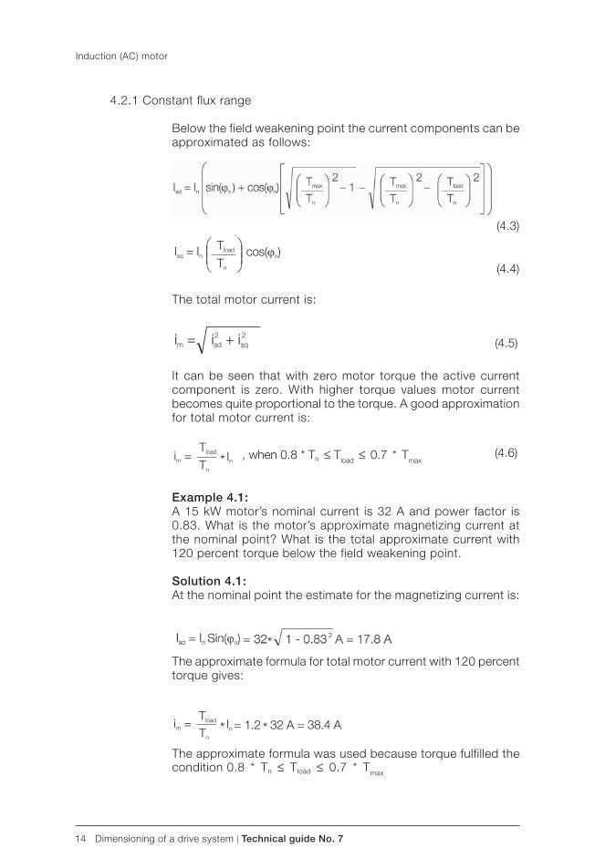
14 Dimensioning of a drive system | Technical guide No. 7
, when 0.8 * Tn ≤ Tload ≤ 0.7 * Tmax
4.2.1 Constant flux range
Below the field weakening point the current components can be approximated as follows:
The total motor current is:
It can be seen that with zero motor torque the active current component is zero. With higher torque values motor current becomes quite proportional to the torque. A good approximation for total motor current is:
Example 4.1:A 15 kW motor’s nominal current is 32 A and power factor is 0.83. What is the motor’s approximate magnetizing current at the nominal point? What is the total approximate current with 120 percent torque below the field weakening point.
Solution 4.1:At the nominal point the estimate for the magnetizing current is:
The approximate formula for total motor current with 120 percent torque gives:
The approximate formula was used because torque fulfilled the condition 0.8 * Tn ≤ Tload ≤ 0.7 * Tmax
(4.5)
(4.3)
(4.4)
(4.6)
Induction (AC) motor
Technical guide No. 7 | Dimensioning of a drive system 15
7
4.2.2 Field weakening range
Above the field weakening point the current components also depend on speed.
Total motor current is:
The motor current can be approximated quite accurately within a certain operating region. The motor current becomes propor-tional to relative power. An approximation formula for current is:
Approximation can be used when:
and
(4.8)
(4.7)
(4.10)
(4.9)
(4.11)
(4.12)
In the field weakening range the additional current needed in order to maintain a certain torque level is proportional to rela-tive speed.
Example 4.2:The motor’s nominal current is 71 A. How much current is needed to maintain the 100 percent torque level at 1.2 times nominal speed (Tmax = 3 * Tn).
Solution 4.2:The current can be calculated by using the approximation for-mula:
Induction (AC) motor
16 Dimensioning of a drive system | Technical guide No. 7
4.3 Motor power
The motor’s mechanical (output) power can be calculated from speed and torque using the formula:
Because motor power is most often given in kilowatts(1 kW = 1000 W) and speed in rpm revolutions per minute,
1 rpm = rad/s), the following formula can be used:
The motor’s input power can be calculated from the voltage, current and power factor:
The motor’s efficiency is the output power divided by the input power:
Example 4.3:The motor nominal power is 15 kW and the nominal speed is 1480 rpm. What is the nominal torque of the motor?
Solution 4.3:The motor’s nominal torque is calculated as follows:
Example 4.4:What is the nominal efficiency of a 37 kW (Pn = 37 kW,Un =380 V, In =71 A and cos(ϕn) = 0.85) motor?
Solution 4.4:The nominal efficiency is:
(4.13)
(4.14)
(4.15)
(4.16)
Induction (AC) motor
Technical guide No. 7 | Dimensioning of a drive system 17
7
Chapter 5 - Basic mechanical laws
5.1 Rotational motion
One of the basic equations of an induction motor describes the relation between moment of inertia ( J [kgm2]), angular velocity ( ω [rad/s]) and torque ( T [Nm]). The equation is as follows:
In the above equation it is assumed that both the frequency and the moment of inertia change. The formula is however often given so that the moment of inertia is assumed to be constant:
Torque Tload represents the load of the motor. The load consists of friction, inertia and the load itself. When the motor speed changes, motor torque is different from Tload . Motor torque can be considered as consisting of a dynamic and a load component:
If the speed and moment of inertia are constants the dynamic component ( Tdyn ) is zero.
The dynamic torque component caused by acceleration/decel-eration of a constant moment of inertia (motor’s speed is changed by Δn [rpm] in time Δt [s], J is constant) is:
The dynamic torque component caused by a variable moment of inertia at constant speed n[rpm] is:
If the moment of inertia varies and at the same time the motor is accelerating the dynamic torque component can be calculated using a certain discrete sampling interval. From the thermal dimensioning point of view it is however often enough to take into account the average moment of inertia during acceleration.
(5.1)
(5.2)
(5.3)
(5.4)
(5.5)
18 Dimensioning of a drive system | Technical guide No. 7
Basic mechanical laws
Example 5.1: The total moment of inertia, 3 kgm2, is accelerated from a speed of 500 rpm to 1000 rpm in 10 seconds. What is the total torque needed when the constant load torque is 50 Nm?
How fast will the motor decelerate to 0 rpm speed if the motor’s electric supply is switched off?
Solution 5.1:The total moment of inertia is constant. The dynamic torque component needed for acceleration is:
Total torque during acceleration is:
If the motor’s electric supply is switched off at 1000 rpm the motor decelerates because of the constant load torque (50 Nm). Following equation holds:
Time to decelerate from 1000 rpm to 0 rpm:
Example 5.2: Accelerating of a fan to nominal speed is done with nominal torque. At nominal speed torque is 87 percent. The fan’s mo-ment of inertia is 1200 kgm2 and the motor’s moment of inertia is 11 kgm2. The load characteristics of the fan Tload is shown in figure 5.1.
Motor nominal power is 200 kW and nominal speed is 991 rpm.
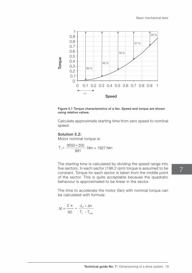
Technical guide No. 7 | Dimensioning of a drive system 19
Speed
Torq
ue
7
Figure 5.1 Torque characteristics of a fan. Speed and torque are shown using relative values.
Calculate approximate starting time from zero speed to nominal speed.
Solution 5.2:Motor nominal torque is:
The starting time is calculated by dividing the speed range into five sectors. In each sector (198.2 rpm) torque is assumed to be constant. Torque for each sector is taken from the middle point of the sector. This is quite acceptable because the quadratic behaviour is approximated to be linear in the sector. The time to accelerate the motor ( fan) with nominal torque can be calculated with formula:
Basic mechanical laws
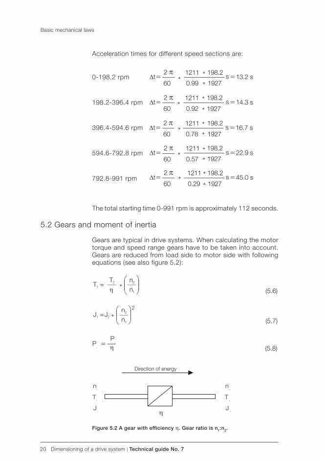
20 Dimensioning of a drive system | Technical guide No. 7
Direction of energy
Basic mechanical laws
Acceleration times for different speed sections are:
0-198.2 rpm
198.2-396.4 rpm
396.4-594.6 rpm
594.6-792.8 rpm
792.8-991 rpm
The total starting time 0-991 rpm is approximately 112 seconds.
5.2 Gears and moment of inertia
Gears are typical in drive systems. When calculating the motor torque and speed range gears have to be taken into account. Gears are reduced from load side to motor side with following equations (see also figure 5.2):
Figure 5.2 A gear with efficiency η. Gear ratio is n1:n2.
(5.6)
(5.7)
(5.8)
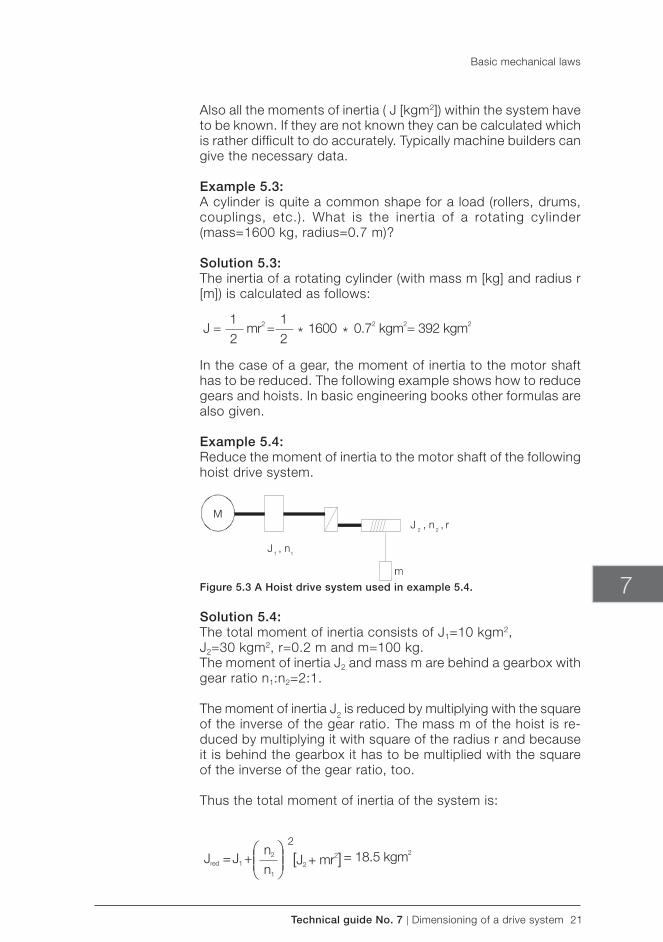
Technical guide No. 7 | Dimensioning of a drive system 21
7
Also all the moments of inertia ( J [kgm2]) within the system have to be known. If they are not known they can be calculated which is rather difficult to do accurately. Typically machine builders can give the necessary data.
Example 5.3:A cylinder is quite a common shape for a load ( rollers, drums, couplings, etc.). What is the inertia of a rotating cylinder (mass=1600 kg, radius=0.7 m)?
Solution 5.3:The inertia of a rotating cylinder (with mass m [kg] and radius r [m]) is calculated as follows:
In the case of a gear, the moment of inertia to the motor shaft has to be reduced. The following example shows how to reduce gears and hoists. In basic engineering books other formulas are also given.
Example 5.4: Reduce the moment of inertia to the motor shaft of the following hoist drive system.
Figure 5.3 A Hoist drive system used in example 5.4.
Solution 5.4: The total moment of inertia consists of J1=10 kgm2,J2=30 kgm2, r=0.2 m and m=100 kg.The moment of inertia J2 and mass m are behind a gearbox with gear ratio n1:n2=2:1.
The moment of inertia J2 is reduced by multiplying with the square of the inverse of the gear ratio. The mass m of the hoist is re-duced by multiplying it with square of the radius r and because it is behind the gearbox it has to be multiplied with the square of the inverse of the gear ratio, too.
Thus the total moment of inertia of the system is:
Basic mechanical laws
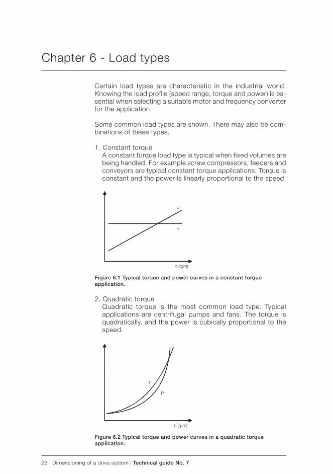
22 Dimensioning of a drive system | Technical guide No. 7
Chapter 6 - Load types
Certain load types are characteristic in the industrial world. Knowing the load profile ( speed range, torque and power) is es-sential when selecting a suitable motor and frequency converter for the application.
Some common load types are shown. There may also be com-binations of these types.
1. Constant torque A constant torque load type is typical when fixed volumes are
being handled. For example screw compressors, feeders and conveyors are typical constant torque applications. Torque is constant and the power is linearly proportional to the speed.
Figure 6.1 Typical torque and power curves in a constant torque application.
2. Quadratic torque Quadratic torque is the most common load type. Typical
applications are centrifugal pumps and fans. The torque is quadratically, and the power is cubically proportional to the speed.
Figure 6.2 Typical torque and power curves in a quadratic torque application.
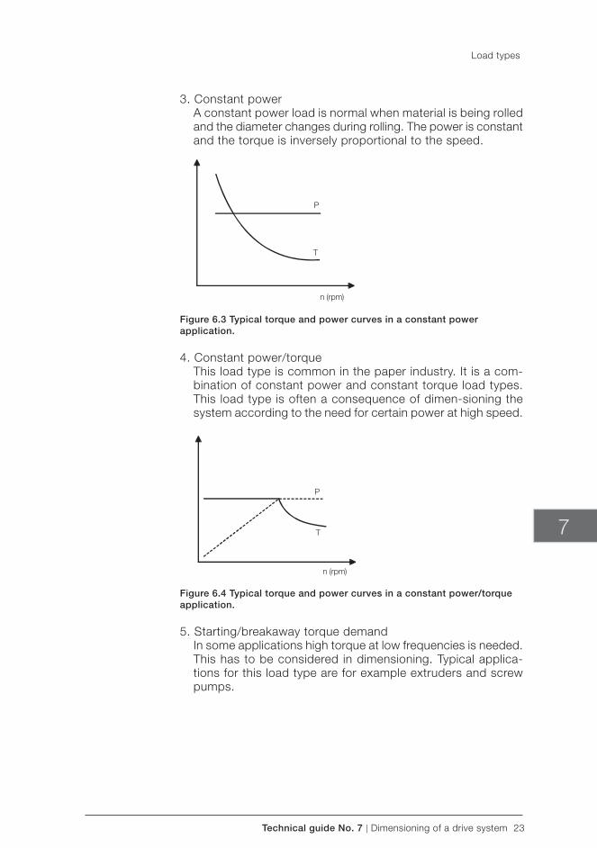
Technical guide No. 7 | Dimensioning of a drive system 23
7
3. Constant power A constant power load is normal when material is being rolled
and the diameter changes during rolling. The power is constant and the torque is inversely proportional to the speed.
Figure 6.3 Typical torque and power curves in a constant power application.
4. Constant power/ torque This load type is common in the paper industry. It is a com-
bination of constant power and constant torque load types. This load type is often a consequence of dimen-sioning the system according to the need for certain power at high speed.
Figure 6.4 Typical torque and power curves in a constant power/ torque application.
5. Starting/breakaway torque demand In some applications high torque at low frequencies is needed.
This has to be considered in dimensioning. Typical applica-tions for this load type are for example extruders and screw pumps.
Load types
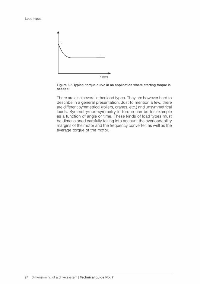
24 Dimensioning of a drive system | Technical guide No. 7
Figure 6.5 Typical torque curve in an application where starting torque is needed.
There are also several other load types. They are however hard to describe in a general presentation. Just to mention a few, there are different symmetrical ( rollers, cranes, etc.) and unsymmetrical loads. Symmetry/non-symmetry in torque can be for example as a function of angle or time. These kinds of load types must be dimensioned carefully taking into account the overloadability margins of the motor and the frequency converter, as well as the average torque of the motor.
Load types
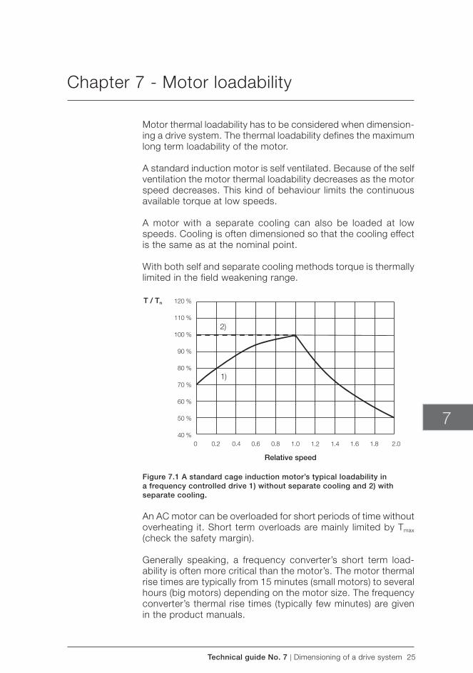
Technical guide No. 7 | Dimensioning of a drive system 25
T / Tn
Relative speed
7
Chapter 7 - Motor loadability
Motor thermal loadability has to be considered when dimension-ing a drive system. The thermal loadability defines the maximum long term loadability of the motor.
A standard induction motor is self ventilated. Because of the self ventilation the motor thermal loadability decreases as the motor speed decreases. This kind of behaviour limits the continuous available torque at low speeds.
A motor with a separate cooling can also be loaded at low speeds. Cooling is often dimensioned so that the cooling effect is the same as at the nominal point.
With both self and separate cooling methods torque is thermally limited in the field weakening range.
Figure 7.1 A standard cage induction motor’s typical loadability in a frequency controlled drive 1) without separate cooling and 2) with separate cooling.
An AC motor can be overloaded for short periods of time without overheating it. Short term overloads are mainly limited by Tmax (check the safety margin).
Generally speaking, a frequency converter’s short term load-ability is often more critical than the motor’s. The motor thermal rise times are typically from 15 minutes (small motors) to several hours (big motors) depending on the motor size. The frequency converter’s thermal rise times (typically few minutes) are given in the product manuals.
26 Dimensioning of a drive system | Technical guide No. 7
Chapter 8 - Selecting the frequency converter and motor
The motor is selected according to the basic information about the process. Speed range, torque curves, ventilation method and motor loadability give guidelines for motor selection. Often it is worth comparing different motors because the selected motor affects the size of the frequency converter.
When selecting a suitable frequency converter there are several things to be considered. Frequency converter manufacturers normally have certain selection tables where typical motor pow-ers for each converter size are given.
The dimensioning current can also be calculated when the torque characteristics is known. The corresponding current values can be calculated from the torque profile and compared to converter current limits. The motor’s nominal current gives some kind of indication. It isn’t however always the best possible dimensioning criteria because motors might for example be derated (ambient temperature, hazardous area, etc.).
The available supply voltage must be checked before selecting the frequency converter. Supply voltage variations affect the available motor shaft power. If the supply voltage is lower than nominal the field weakening point shifts to a lower frequency and the available maximum torque of the motor is reduced in the field weakening range.
The maximum available torque is often limited by the frequency converter. This has to be considered already in the motor selec-tion phase. The frequency converter may limit the motor torque earlier than stated in the motor manufacturer’s data sheet.
The maximum available torque is also affected by transform-ers, reactors, cables, etc. in the system because they cause a voltage drop and thus the maximum available torque may drop. The system’s power losses need to be compensated also by the frequency converter rating.
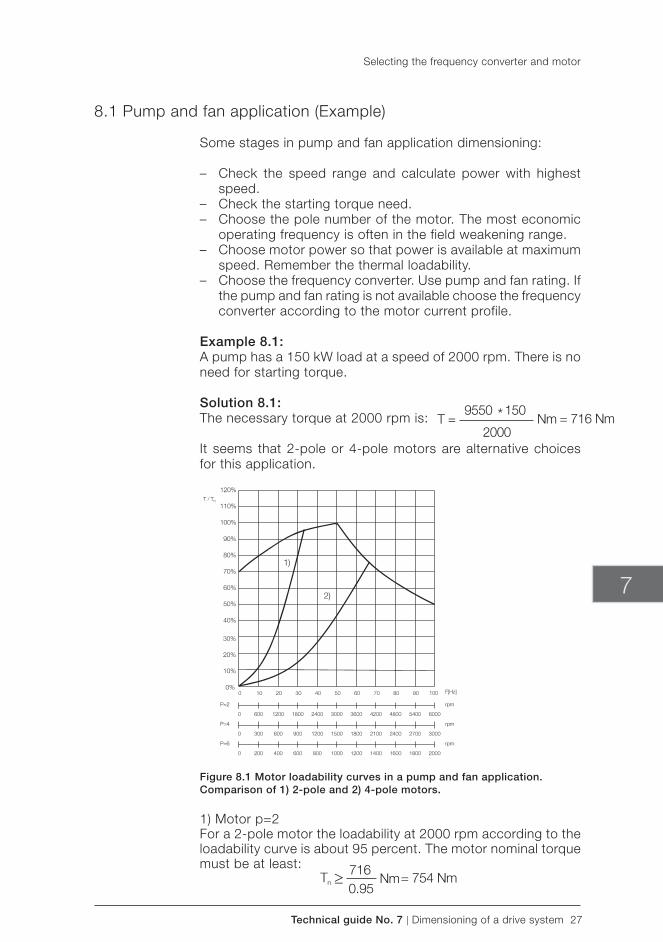
Technical guide No. 7 | Dimensioning of a drive system 27
7
8.1 Pump and fan application (Example)
Some stages in pump and fan application dimensioning:
– Check the speed range and calculate power with highest speed.
– Check the starting torque need. – Choose the pole number of the motor. The most economic
operating frequency is often in the field weakening range. – Choose motor power so that power is available at maximum
speed. Remember the thermal loadability. – Choose the frequency converter. Use pump and fan rating. If
the pump and fan rating is not available choose the frequency converter according to the motor current profile.
Example 8.1:A pump has a 150 kW load at a speed of 2000 rpm. There is no need for starting torque.
Solution 8.1:The necessary torque at 2000 rpm is:
It seems that 2-pole or 4-pole motors are alternative choices for this application.
Figure 8.1 Motor loadability curves in a pump and fan application. Comparison of 1) 2-pole and 2) 4-pole motors.
1) Motor p=2For a 2-pole motor the loadability at 2000 rpm according to the loadability curve is about 95 percent. The motor nominal torque must be at least:
Selecting the frequency converter and motor
28 Dimensioning of a drive system | Technical guide No. 7
Selecting the frequency converter and motor
The corresponding nominal power must then be at least:
A 250 kW (400 V, 431 A, 50 Hz, 2975 rpm and 0.87) motor is selected. The nominal torque of the motor is:
The motor current at 2000 rpm speed ( constant flux range) is approximately:
The minimum continuous current for the frequency converter is then 384 A.
2) motor p=4 For a 4-pole motor the loadability at 2000 rpm is 75 percent.The minimum nominal torque of the motor is:
The minimum power for a 4-pole motor is:
A 160 kW motor (400 V, 305 A, 50 Hz, 1480 rpm and 0.81) fulfills the conditions. The approximated current at a speed of 2000 rpm (66.7 Hz) is:
The exact current should be calculated if the selected frequency converter’s nominal current is close to the approximated motor current.
A 4-pole motor requires less current at the pump operation point. Thus it is probably a more economical choice than a 2-pole motor.
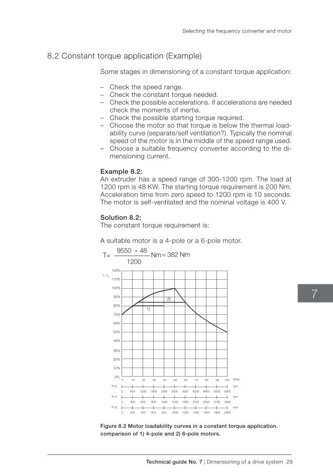
Technical guide No. 7 | Dimensioning of a drive system 29
7
8.2 Constant torque application (Example)
Some stages in dimensioning of a constant torque application:
– Check the speed range. – Check the constant torque needed. – Check the possible accelerations. If accelerations are needed
check the moments of inertia. – Check the possible starting torque required. – Choose the motor so that torque is below the thermal load-
ability curve (separate/self ventilation?). Typically the nominal speed of the motor is in the middle of the speed range used.
– Choose a suitable frequency converter according to the di-mensioning current.
Example 8.2:An extruder has a speed range of 300-1200 rpm. The load at 1200 rpm is 48 KW. The starting torque requirement is 200 Nm. Acceleration time from zero speed to 1200 rpm is 10 seconds. The motor is self-ventilated and the nominal voltage is 400 V.
Solution 8.2:The constant torque requirement is:
A suitable motor is a 4-pole or a 6-pole motor.
Figure 8.2 Motor loadability curves in a constant torque application. comparison of 1) 4-pole and 2) 6-pole motors.
Selecting the frequency converter and motor
30 Dimensioning of a drive system | Technical guide No. 7
Selecting the frequency converter and motor
1) Motor p=4At 300 rpm speed the thermal loadability is 80 percent.The estimated minimum nominal torque is:
The minimum motor nominal power is:
A suitable motor is for example a 75 kW (400 V, 146 A, 50 Hz, 1473 rpm and 0.82) motor. The motor nominal torque is:
Motor current is approximately (T/Tn ≈ 0.8):
According to the calculated motor current a suitable frequency converter can be selected for constant torque use.
The starting torque requirement (200 Nm) is not a problem for this motor.
If the motor’s moment of inertia is 0.72 kgm2 the dynamic torque in acceleration is:
Thus the total torque during acceleration is 391 Nm which is less than the nominal torque of the motor.
2) Motor p=6At speeds of 300 rpm and 1200 rpm the motor loadability is 84 percent. Thus the minimum nominal torque of the 6-pole motor is:
The minimum value of the motor nominal power is:
Technical guide No. 7 | Dimensioning of a drive system 31
7
A suitable motor could be for example a 55 kW (400 V, 110 A, 50 Hz, 984 rpm and 0.82) motor. The motor nominal torque is:
The dimensioning current can be approximated at a speed of 1200 rpm:
The nominal (continuous) current of the frequency converter must be over 96 A.
The starting torque requirement is less than motor’s nominal torque.
If the inertia of the motor is 1.2 kgm2 the dynamic torque in ac-celeration is:
The total torque needed during acceleration is 397 Nm which is less than the nominal torque of the motor.
A 6-pole motor current is 19 A smaller than with a 4-pole motor. The final frequency converter/motor selection depends on the motor and frequency converter frame sizes and prices.
8.3 Constant power application (Example)
Some stages in dimensioning of a constant power application:
– Check the speed range. – Calculate the power needed. Winders are typical constant
power applications. – Dimension the motor so that the field weakening range is
utilized.
Example 8.3:A wire drawing machine is controlled by a frequency converter. The surface speed of the reel is 12 m/s and the tension is 5700 N. The diameters of the reel are 630 mm (empty reel) and 1250 (full reel). There is a gear with gear ratio n2 :n1 =1:7.12 and the efficiency of the gear is 0.98.
Select a suitable motor and converter for this application.
Selecting the frequency converter and motor
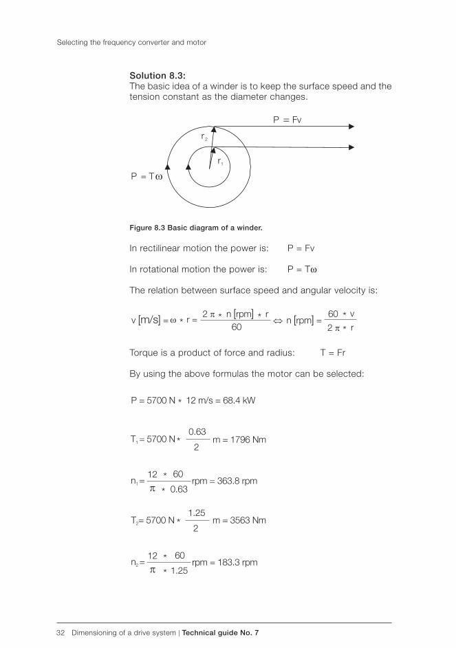
32 Dimensioning of a drive system | Technical guide No. 7
Selecting the frequency converter and motor
Solution 8.3:The basic idea of a winder is to keep the surface speed and the tension constant as the diameter changes.
Figure 8.3 Basic diagram of a winder.
In rectilinear motion the power is: P = Fv
In rotational motion the power is: P = Tω
The relation between surface speed and angular velocity is:
Torque is a product of force and radius: T = Fr
By using the above formulas the motor can be selected:
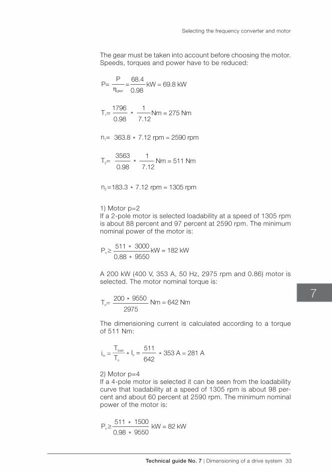
Technical guide No. 7 | Dimensioning of a drive system 33
7
The gear must be taken into account before choosing the motor. Speeds, torques and power have to be reduced:
1) Motor p=2If a 2-pole motor is selected loadability at a speed of 1305 rpm is about 88 percent and 97 percent at 2590 rpm. The minimum nominal power of the motor is:
A 200 kW (400 V, 353 A, 50 Hz, 2975 rpm and 0.86) motor is selected. The motor nominal torque is:
The dimensioning current is calculated according to a torque of 511 Nm:
2) Motor p=4If a 4-pole motor is selected it can be seen from the loadability curve that loadability at a speed of 1305 rpm is about 98 per-cent and about 60 percent at 2590 rpm. The minimum nominal power of the motor is:
Selecting the frequency converter and motor
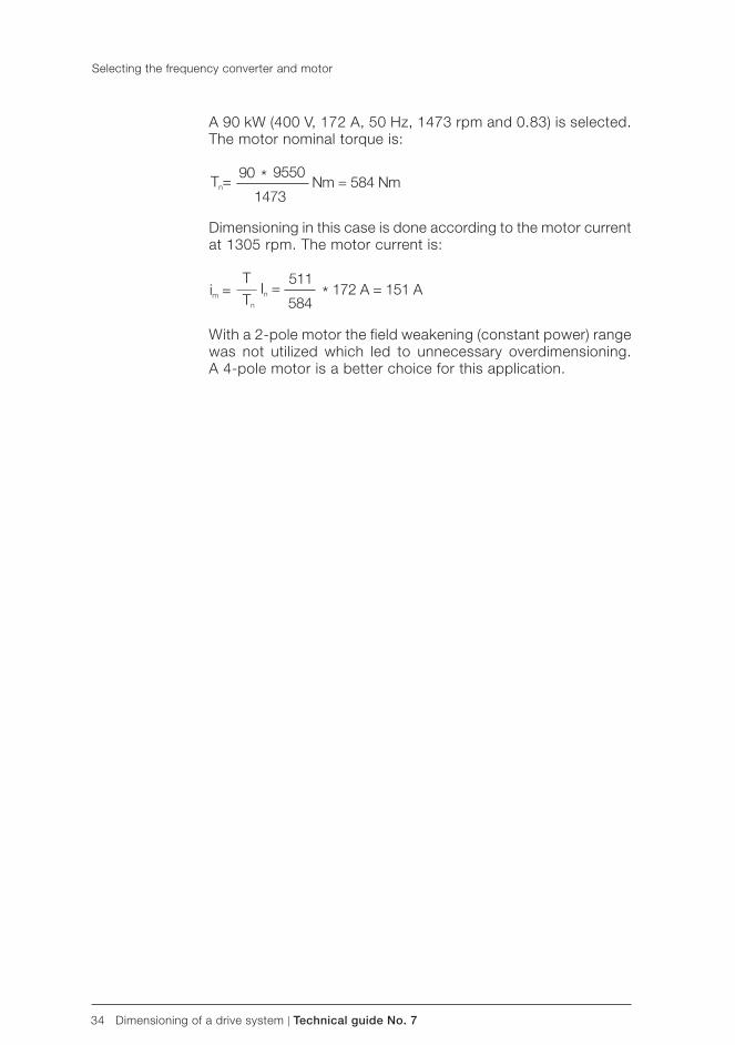
34 Dimensioning of a drive system | Technical guide No. 7
A 90 kW (400 V, 172 A, 50 Hz, 1473 rpm and 0.83) is selected. The motor nominal torque is:
Dimensioning in this case is done according to the motor current at 1305 rpm. The motor current is:
With a 2-pole motor the field weakening ( constant power) range was not utilized which led to unnecessary overdimensioning. A 4-pole motor is a better choice for this application.
Selecting the frequency converter and motor
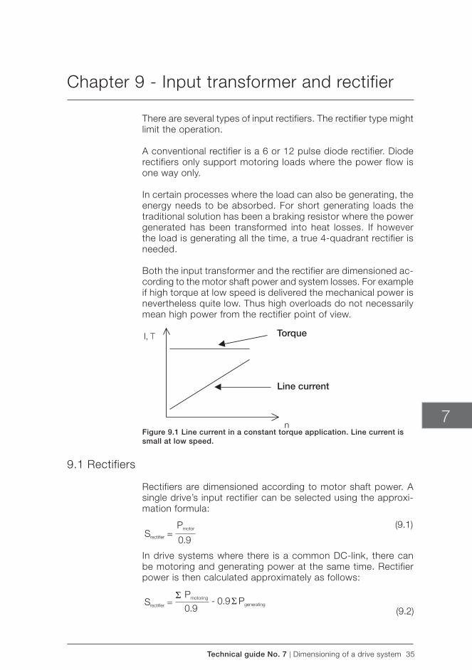
Technical guide No. 7 | Dimensioning of a drive system 35
Torque
Line current
7
Chapter 9 - Input transformer and rectifier
There are several types of input rectifiers. The rectifier type might limit the operation.
A conventional rectifier is a 6 or 12 pulse diode rectifier. Diode rectifiers only support motoring loads where the power flow is one way only.
In certain processes where the load can also be generating, the energy needs to be absorbed. For short generating loads the traditional solution has been a braking resistor where the power generated has been transformed into heat losses. If however the load is generating all the time, a true 4-quadrant rectifier is needed.
Both the input transformer and the rectifier are dimensioned ac-cording to the motor shaft power and system losses. For example if high torque at low speed is delivered the mechanical power is nevertheless quite low. Thus high overloads do not necessarily mean high power from the rectifier point of view.
Figure 9.1 Line current in a constant torque application. Line current is small at low speed.
9.1 Rectifiers
Rectifiers are dimensioned according to motor shaft power. A single drive’s input rectifier can be selected using the approxi-mation formula:
In drive systems where there is a common DC-link, there can be motoring and generating power at the same time. Rectifier power is then calculated approximately as follows:
(9.1)
(9.2)
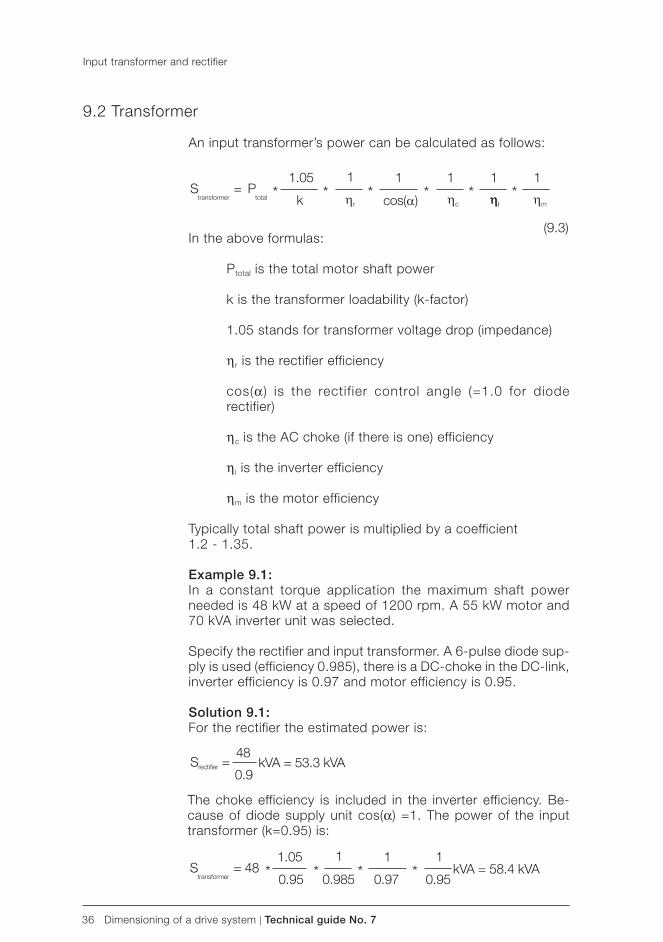
36 Dimensioning of a drive system | Technical guide No. 7
9.2 Transformer
An input transformer’s power can be calculated as follows:
In the above formulas:
Ptotal is the total motor shaft power
k is the transformer loadability (k-factor)
1.05 stands for transformer voltage drop (impedance)
ηr is the rectifier efficiency
cos(α) is the rectif ier control angle (=1.0 for diode rectifier)
ηc is the AC choke (if there is one) efficiency
ηi is the inverter efficiency
ηm is the motor efficiency
Typically total shaft power is multiplied by a coefficient1.2 - 1.35.
Example 9.1:In a constant torque application the maximum shaft power needed is 48 kW at a speed of 1200 rpm. A 55 kW motor and 70 kVA inverter unit was selected.
Specify the rectifier and input transformer. A 6-pulse diode sup-ply is used ( efficiency 0.985), there is a DC-choke in the DC-link, inverter efficiency is 0.97 and motor efficiency is 0.95.
Solution 9.1:For the rectifier the estimated power is:
Input transformer and rectifier
(9.3)
The choke efficiency is included in the inverter efficiency. Be-cause of diode supply unit cos(α) =1. The power of the input transformer (k=0.95) is:
Technical guide No. 7 | Dimensioning of a drive system 37
7
Symbols4-quadrant 35
Aacceleration 17, 18, 29, 30, 31AC motor 8active current 13, 14angular velocity 17, 32
Ccentrifugal pumps 22constant flux range 12, 13, 28constant power 12, 23, 31, 34constant torque 22, 23, 29, 30, 35, 36coupling 21cubically 22cyclical load 9
DDC-link 8, 35, 36decelerate 18drum 21
Eefficiency 16, 20, 31, 36electric supply 7, 8, 18
Ffan 18, 19, 22, 27field weakening range 12, 13, 15, 25, 26, 27, 31flux range 12, 13, 14, 28frequency 8, 9, 10, 11, 12, 17, 22, 24, 25, 26, 27, 28, 29, 30, 31, 32, 33, 34friction 17
Ggear 20, 21, 31, 32generating 35
Iinduction 11, 12, 13, 14, 15, 16, 17, 25induction motor 11, 12, 13, 17, 25input transformer 8, 35, 36inverter 8, 36
Kkilowatt 16
Lload 8, 9, 10, 12, 14, 17, 18, 20, 21, 22, 23, 24, 25, 26, 27, 28, 29, 30, 33, 35, 36load profile 22load type 9, 22, 23, 24locked rotor torque 11
Mmaximum torque 9, 12, 26mechanical 11, 16, 17, 18, 19, 20, 21, 35motor 7, 8, 9, 10, 11, 12, 13, 14, 15, 16, 17, 18, 19, 20, 21, 22, 24, 25, 26, 27, 28, 29, 30, 31, 32, 33, 34, 35, 36motoring 35
Nnominal point 11, 13, 14, 25
Ooverloadability 9, 24
Ppower 9, 11, 12, 14, 15, 16, 18, 22, 23, 26, 27, 28, 30, 31, 32, 33, 34, 35, 36power factor 14, 16pull-out torque 12pull-up torque 11
Qquadratically 22quadratic torque 22
Rreactive current 13rectifier 8, 35, 36rectifier unit 8roller 21, 24
Sseparate cooling 25shaft power 26, 35, 36slip 11, 12speed 9, 11, 12, 13, 15, 16, 17, 18, 19, 20, 22, 23, 25, 27, 28, 29, 30, 31, 32, 33, 35, 36speed range 19, 20, 22, 27, 29, 31starting torque 9, 24, 27, 29, 30, 31supply 7, 8, 9, 11, 18, 26, 36supply voltage 9, 26
Tthermal loadability 25, 27, 29, 30torque 9, 10, 11, 12, 13, 14, 15, 16, 17, 18, 19, 20, 22, 23, 24, 25, 26, 27, 28, 29, 30, 31, 33, 34, 35, 36transformer 8, 26, 35, 36
Vvoltage 9, 11, 12, 13, 16, 26, 29, 36
Chapter 10 - Index

38 Dimensioning of a drive system | Technical guide No. 7

3AFE
6436
2569
RE
V C
EN
28.
4.20
11 #
1564
9
Contact us
For more information please contact your local ABB representative or visit:
www.abb.com/driveswww.abb.com/drivespartners
© Copyright 2011 ABB. All rights reserved. Specifications subject to change without notice.

Technical guide No. 8Electrical braking
ABB drives

2 Electrical braking | Technical guide No. 8

Technical guide No. 8 | Electrical braking 3
© Copyright 2011 ABB. All rights reserved.
Specifications subject to change without notice.
3AFE64362534 REV B EN 6.5.2011
Technical guide No. 8Electrical braking
8

4 Electrical braking | Technical guide No. 8
Technical guide No. 8 | Electrical braking 5
8
Chapter 1 - Introduction ............................................................................7
1.1 General ........................................................................................71.2 Drive applications map according to speed and torque ...................7
Chapter 2 - Evaluating braking power .......................................................9
2.1 General dimension principles for electrical braking .........................92.2 Basics of load descriptions .........................................................10
2.2.1 Constant torque and quadratic torque ..................................102.2.2 Evaluating brake torque and power ......................................102.2.3 Summary and conclusions ...................................................14
Chapter 3 - Electrical braking solution in drives ......................................15
3.1 Motor flux braking .......................................................................153.2 Braking chopper and braking resistor ..........................................16
3.2.1 The energy storage nature of the frequency converter ...........163.2.2 Principle of the braking chopper ..........................................17
3.3 Anti-parallel thyristor bridge configuration ....................................193.4 IGBT bridge configuration ...........................................................21
3.4.1 General principles of IGBT based regeneration units .............213.4.2 IGBT based regeneration - control targets ............................213.4.3 Direct torque control in the form of direct power control ........223.4.4 Dimensioning an IGBT regeneration unit ...............................24
3.5 Common DC ..............................................................................24
Chapter 4 - Evaluating the life cycle cost of different forms of electrical braking .....................................................................................26
4.1 Calculating the direct cost of energy ............................................264.2 Evaluating the investment cost ....................................................264.3 Calculating the life cycle cost ......................................................27
Chapter 5 - Symbols and definitions .......................................................31
Chapter 6 - Index .....................................................................................32
Contents

6 Electrical braking | Technical guide No. 8
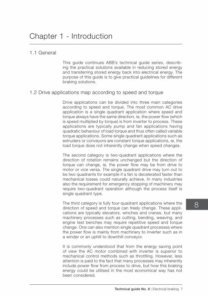
Technical guide No. 8 | Electrical braking 7
8
Chapter 1 - Introduction
1.1 General
This guide continues ABB’s technical guide series, describ-ing the practical solutions available in reducing stored energy and transferring stored energy back into electrical energy. The purpose of this guide is to give practical guidelines for different braking solutions.
1.2 Drive applications map according to speed and torque
Drive applications can be divided into three main categories according to speed and torque. The most common AC drive application is a single quadrant application where speed and torque always have the same direction, ie, the power flow (which is speed multiplied by torque) is from inverter to process. These applications are typically pump and fan applications having quadratic behaviour of load torque and thus often called variable torque applications. Some single quadrant applications such as extruders or conveyors are constant torque applications, ie, the load torque does not inherently change when speed changes.
The second category is two-quadrant applications where the direction of rotation remains unchanged but the direction of torque can change, ie, the power flow may be from drive to motor or vice versa. The single quadrant drive may turn out to be two quadrants for example if a fan is decelerated faster than mechanical losses could naturally achieve. In many industries also the requirement for emergency stopping of machinery may require two-quadrant operation although the process itself is single quadrant type. The third category is fully four-quadrant applications where the direction of speed and torque can freely change. These appli-cations are typically elevators, winches and cranes, but many machinery processes such as cutting, bending, weaving, and engine test benches may require repetitive speed and torque change. One can also mention single quadrant processes where the power flow is mainly from machinery to inverter such as in a winder or an uphill to downhill conveyor.
It is commonly understood that from the energy saving point of view the AC motor combined with inverter is superior to mechanical control methods such as throttling. However, less attention is paid to the fact that many processes may inherently include power flow from process to drive, but how this braking energy could be utilised in the most economical way has not been considered.
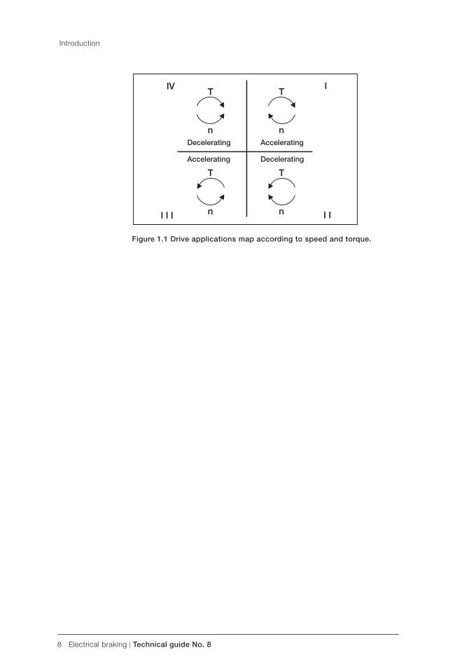
8 Electrical braking | Technical guide No. 8
Decelerating Accelerating
Accelerating Decelerating
Figure 1.1 Drive applications map according to speed and torque.
Introduction

Technical guide No. 8 | Electrical braking 9
8
2.1 General dimension principles for electrical braking
The evaluation of braking need starts from the mechanics. Typi-cally, the requirement is to brake the mechanical system within a specified time, or there are subcycles in the process where the motor operates on the generator side at constant or slightly varying speed.
It is important to note that devices used in electrical braking are dimensioned according to braking power. The mechanical braking power depends on braking torque and speed, formula (2.1). The higher the speed the higher the power. This power is then transferred at a certain specified voltage and current. The higher the voltage the less current is needed for the same power, formula (2.2). The current is the primary component defining the cost in low voltage AC drives.
In formula (2.2) we see the term cosφ. This term defines how much motor current is used for magnetising the motor. The magnetising current does not create any torque and is therefore ignored.
On the other hand, this motor magnetising current is not taken from the AC supply feeding the converter, ie, the current to the inverter is lower than the current fed to the motor. This fact means that on the supplying side the cosφ is typically near 1.0. Note that in formula (2.2) it has been assumed that no loss occurs when DC power is converted to AC power. There are some losses in this conversion, but in this context the losses can be ignored.
Chapter 2 - Evaluating braking power
(2.1)
(2.2)
10 Electrical braking | Technical guide No. 8
Evaluating braking power
2.2 Basics of load descriptions
Typically loads are categorised as constant torque or quadratic torque type. Quadratic load torque means that the load torque is proportional to the square of the speed. It also means that the power is speed to the power of three. In constant torque applications, the power is directly proportional to speed.
2.2.1 Constant torque and quadratic torque
Constant torque:
C: constant
Quadratic torque:
2.2.2 Evaluating brake torque and power
In the case of steady state operation (the angular acceleration α is zero) the motor torque has to make friction torque correspond proportionally to the angular speed and load torque at that specific angular speed. The braking torque and power need in respect to time varies greatly in these two different load types.
(2.7)
Let us first consider the case where the load is constant torque type and the drive system is not able to generate braking torque, ie, the drive itself is single quadrant type. In order to calculate the braking time needed one can apply the following equation. Please note that formula (2.7) underlines that the torque needed for inertia accelerating (or decelerating), friction and load torque is in the opposite direction to the motor torque.
(2.8)
In practice, it is difficult to define the effect of friction exactly. By assuming friction to be zero the time calculated is on the safe side.
(2.3)
(2.4)
(2.5)
(2.6)
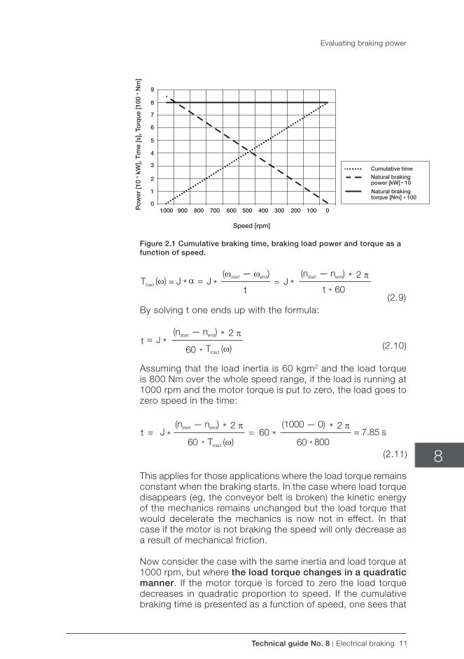
Technical guide No. 8 | Electrical braking 11
Po
wer
[10
* kW
], T
ime
[s],
Torq
ue [1
00 *
Nm
]
Cumulative time
Natural brakingpower [kW] * 10
Natural brakingtorque [Nm] * 100
Speed [rpm]
8
Figure 2.1 Cumulative braking time, braking load power and torque as a function of speed.
(2.9)
(2.11)
(2.10)
By solving t one ends up with the formula:
Assuming that the load inertia is 60 kgm2 and the load torque is 800 Nm over the whole speed range, if the load is running at 1000 rpm and the motor torque is put to zero, the load goes to zero speed in the time:
This applies for those applications where the load torque remains constant when the braking starts. In the case where load torque disappears (eg, the conveyor belt is broken) the kinetic energy of the mechanics remains unchanged but the load torque that would decelerate the mechanics is now not in effect. In that case if the motor is not braking the speed will only decrease as a result of mechanical friction.
Now consider the case with the same inertia and load torque at 1000 rpm, but where the load torque changes in a quadratic manner. If the motor torque is forced to zero the load torque decreases in quadratic proportion to speed. If the cumulative braking time is presented as a function of speed, one sees that
Evaluating braking power
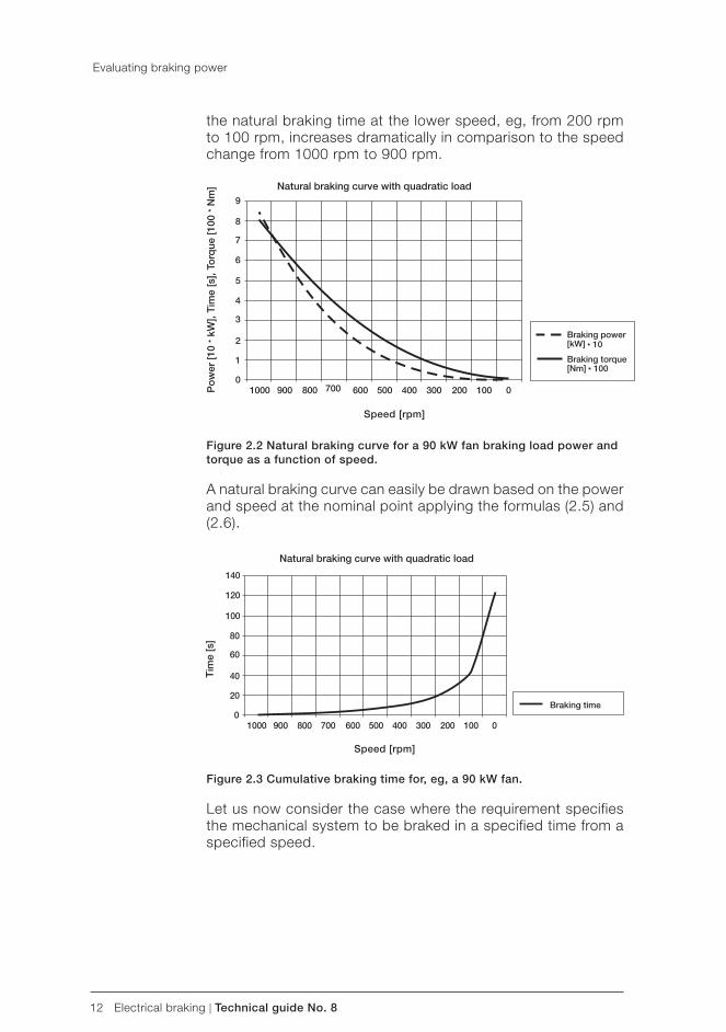
12 Electrical braking | Technical guide No. 8
Natural braking curve with quadratic load
Po
wer
[10
* kW
], T
ime
[s],
Torq
ue [1
00 *
Nm
]
Braking power[kW] * 10
Braking torque[Nm] * 100
Speed [rpm]
Tim
e [s
]
Braking time
Natural braking curve with quadratic load
Speed [rpm]
the natural braking time at the lower speed, eg, from 200 rpm to 100 rpm, increases dramatically in comparison to the speed change from 1000 rpm to 900 rpm.
Figure 2.2 Natural braking curve for a 90 kW fan braking load power and torque as a function of speed.
A natural braking curve can easily be drawn based on the power and speed at the nominal point applying the formulas (2.5) and (2.6).
Figure 2.3 Cumulative braking time for, eg, a 90 kW fan.
Let us now consider the case where the requirement specifies the mechanical system to be braked in a specified time from a specified speed.
Evaluating braking power
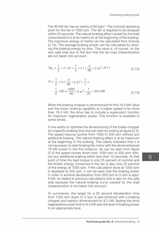
Technical guide No. 8 | Electrical braking 13
8
The 90 kW fan has an inertia of 60 kgm2. The nominal operating point for the fan is 1000 rpm. The fan is required to be stopped within 20 seconds. The natural braking effect caused by the load characteristics is at its maximum at the beginning of the braking. The maximum energy of inertia can be calculated from formula (2.12). The average braking power can be calculated by divid-ing this braking energy by time. This value is, of course, on the very safe side due to the fact that the fan load characteristics are not taken into account.
(2.12)
(2.13)
When the braking chopper is dimensioned for this 16.4 kW value and the motor braking capability at a higher speed is far more than 16.4 kW, the drive has to include a supervision function for maximum regeneration power. This function is available in some drives.
If one wants to optimise the dimensioning of the brake chopper for a specific braking time one can start by looking at figure (2.3). The speed reduces quickly from 1000 to 500 rpm without any additional braking. The natural braking effect is at its maximum at the beginning of the braking. This clearly indicates that it is not necessary to start braking the motor with the aforementioned 16 kW power in the first instance. As can be seen from figure (2.3) the speed comes down from 1000 rpm to 500 rpm with-out any additional braking within less than 10 seconds. At that point of time the load torque is only 25 percent of nominal and the kinetic energy conserved in the fan is also only 25 percent of the energy at 1000 rpm. If the calculation done at 1000 rpm is repeated at 500 rpm, it can be seen that the braking power in order to achieve deceleration from 500 rpm to 0 rpm is appr. 8 kW. As stated in previous calculations this is also on the safe side because the natural braking curve caused by the load characteristics is not taken into account.
To summarise, the target for a 20 second deceleration time from 1000 rpm down to 0 rpm is well achieved with a braking chopper and resistor dimensioned for 8.2 kW. Setting the drive regenerative power limit to 8.2 kW sets the level of braking power to an appropriate level.
Evaluating braking power
14 Electrical braking | Technical guide No. 8
2.2.3 Summary and conclusions
There are two basic load types: constant and quadratic load torque.
Constant torque application:
– The load torque characteristic does not depend on the speed. The load torque remains approximately the same over the whole speed area.
– The power increases linearly as the speed increases and vice versa.
– Typical constant torque applications: cranes and conveyors.
Quadratic torque application:
– The load torque increases to speed to the power of two. – When the speed increases, the power increases to speed to
the power of three. – Typical quadratic torque applications: fans and pumps.
Braking power evaluation:
– The quadratic load characteristics mean fast natural decel-eration between 50-100 percent of nominal speeds. That should be utilised when dimensioning the braking power needed.
– The quadratic load torque means that at low speeds the natural deceleration is mainly due to friction.
– The constant load torque characteristic is constant natural deceleration.
– The braking power is a function of torque and speed at that specified operating point. Dimensioning the braking chopper according to peak braking power typically leads to overdimensioning.
– The braking power is not a function of motor nominal cur-rent (torque) or power as such.
– If the load torque disappears when braking starts the natural braking effect is small. This affects the dimensioning of the braking chopper.
Evaluating braking power
(2.14)
(2.15)
Technical guide No. 8 | Electrical braking 15
8
Chapter 3 - Electrical braking solution in drives
The modern AC drive consists of an input rectifier converting AC voltage to DC voltage stored in DC capacitors. The inverter converts the DC voltage back to AC voltage feeding the AC motor at the desired frequency. The process power needed flows through the rectifier, DC bus and inverter to the motor. The amount of energy stored in DC capacitors is very small compared with the power needed, ie, the rectifier has to constantly deliver the power needed by the motor plus the losses in drive system.
3.1 Motor flux braking
Flux braking is a method based on motor losses. When braking in the drive system is needed, the motor flux and thus also the magnetising current component used in the motor are increased. The control of flux can be easily achieved through the direct torque control principle (for more information about DTC see Technical guide No. 1). With DTC the inverter is directly controlled to achieve the desired torque and flux for the motor. During flux braking the motor is under DTC control which guarantees that braking can be made according to the specified speed ramp. This is very different to the DC injection braking typically used in drives. In the DC injection method DC current is injected to the motor so that control of the motor flux is lost during braking. The flux braking method based on DTC enables the motor to shift quickly from braking to motoring power when requested.
In flux braking the increased current means increased losses inside the motor. The braking power is therefore also increased although the braking power delivered to the frequency converter is not increased. The increased current generates increased losses in motor resistances. The higher the resistance value the higher the braking energy dissipation inside the motor. Typically, in low power motors (below 5 kW) the resistance value of the motor is relatively large in respect to the nominal current of the motor. The higher the power or the voltage of the motor the less the resistance value of the motor in respect to motor current. In other words, flux braking is most effective in a low power motor.
16 Electrical braking | Technical guide No. 8
Braking torque (%)
No fl ux braking
Flux brakingRated motor power
Figure 3.1 Percentage of motor braking torque of rated torque as a function of output frequency.
The main benefits of flux braking are:
– No extra components are needed and no extra cost, using DTC control method.
– The motor is controlled during braking unlike in the DC injec-tion current braking typically used in drives.
The main drawbacks of flux braking are:
– Increased thermal stress on the motor if braking is repeated over short periods.
– Braking power is limited by the motor characteristics eg, resistance value.
– Flux braking is useful mainly in low power motors.
3.2 Braking chopper and braking resistor
3.2.1 The energy storage nature of the frequency converter
In standard drives the rectifier is typically a 6-pulse or 12-pulse diode rectifier only able to deliver power from the AC network to the DC bus but not vice versa. If the power flow changes as in two or four quadrant applications, the power fed by the process charges the DC capacitors according to formula (3.1) and the DC bus voltage starts to rise. The capacitance C is a relatively low value in an AC drive resulting in fast voltage rise, and the components of a frequency converter may only withstand volt-age up to a certain specified level.
Electrical braking solution in drives
Technical guide No. 8 | Electrical braking 17
8
In order to prevent the DC bus voltage rising excessively, two possibilities are available: the inverter itself prevents the power flow from process to frequency converter. This is done by limit-ing the braking torque to keep a constant DC bus voltage level. This operation is called overvoltage control and it is a standard feature of most modern drives. However, this means that the braking profile of the machinery is not done according to the speed ramp specified by the user.
The energy storage capacity of the inverter is typically very small. For example, for a 90 kW drive the capacitance value is typically 5 mF. If the drive is supplied by 400 V AC the DC bus has the value of 1.35 * 400 = 565 V DC. Assuming that the capacitors can withstand a maximum of 735 V DC, the time which 90 kW nominal power can be fed to the DC capacitor can be calculated from:
(3.1)
(3.2)
(3.3)
This range of values applies generally for all modern low volt-age AC drives regardless of their nominal power. In practice this means that the overvoltage controller and its ‘work horse’ torque controller of the AC motor has to be a very fast one. Also the activation of the regeneration or braking chopper has to be very fast when used in drive configuration.
3.2.2 Principle of the braking chopper
The other possibility to limit DC bus voltage is to lead the brak-ing energy to a resistor through a braking chopper. The braking chopper is an electrical switch that connects DC bus voltage to a resistor where the braking energy is converted to heat. The braking choppers are automatically activated when the actual DC bus voltage exceeds a specified level depending on the nominal voltage of the inverter.
Electrical braking solution in drives
18 Electrical braking | Technical guide No. 8
UDC+
UDC-
R+
R-
V1
C1 ControlCircuit
Figure 3.2 Circuit diagram example of braking chopper. UDC represents DC bus terminals and R the resistor terminals.
The main benefits of the braking chopper and resistor solution are:
– Simple electrical construction and well-known technology. – Low fundamental investment for chopper and resistor. – The chopper works even if AC supply is lost. Braking during
main power loss may be required, eg, in elevator or other safety related applications.
The main drawbacks of the braking chopper and resistor are:
– The braking energy is wasted if the heated air can not be utilised.
– The braking chopper and resistors require addit ional space.
– May require extra investments in the cooling and heat recovery system.
– Braking choppers are typically dimensioned for a certain cy-cle, eg, 100 percent power 1/10 minutes, long braking times require more accurate dimensioning of the braking chopper.
– Increased risk of fire due to hot resistor and possible dust and chemical components in the ambient air space.
– The increased DC bus voltage level during braking causes additional voltage stress on motor insulation.
When to apply a braking chopper:
– The braking cycle is needed occasionally. – The amount of braking energy with respect to motoring
energy is extremely small. – Braking operation is needed during main power loss.
Electrical braking solution in drives
Technical guide No. 8 | Electrical braking 19
Forward Reverse
Udc3
8
When to consider other solutions than braking chopper and resistor:
– The braking is continuous or regularly repeated. – The total amount of braking energy is high in respect to the
motoring energy needed. – The instantaneous braking power is high, eg, several hun-
dred kW for several minutes. – The ambient air includes substantial amounts of dust or other
potentially combustible or explosive or metallic components.
3.3 Anti-parallel thyristor bridge configuration
In a frequency converter the diode rectifier bridges can be re-placed by the two thyristor controlled rectifiers in antiphase. This configuration allows changing the rectifier bridge according to the power flow needed in the process.
The main components of the thyristor supply unit are two 6-pulse thyristor bridges. The forward bridge converts 3-phase AC supply into DC. It feeds power to the drives (inverters) via the intermedi-ate circuit. The reverse bridge converts DC back to AC whenever there is a need to pass the surplus motor braking power back to the supply network.
Figure 3.3 Line diagram of anti-parallel thyristor supply unit.
Only one bridge operates at a time, the other one is blocked. The thyristor-firing angle is constantly regulated to keep the intermedi-ate circuit voltage at the desired level. The forward/reverse bridge selection and intermediate circuit voltage control are based on the measurement of the supply current, supply voltage and the intermediate circuit voltage. The DC reactor filters the current peaks of the intermediate circuit.
Electrical braking solution in drives
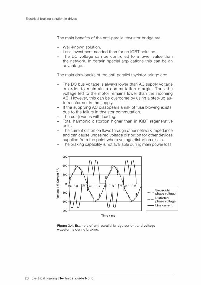
20 Electrical braking | Technical guide No. 8
Volta
ge
/ V,
Cur
rent
/ A
Time / ms
The main benefits of the anti-parallel thyristor bridge are:
– Well-known solution. – Less investment needed than for an IGBT solution. – The DC voltage can be controlled to a lower value than
the network. In certain special applications this can be an advantage.
The main drawbacks of the anti-parallel thyristor bridge are:
– The DC bus voltage is always lower than AC supply voltage in order to maintain a commutation margin. Thus the voltage fed to the motor remains lower than the incoming AC. However, this can be overcome by using a step-up au-totransformer in the supply.
– If the supplying AC disappears a risk of fuse blowing exists, due to the failure in thyristor commutation.
– The cosφ varies with loading. – Total harmonic distortion higher than in IGBT regenerative
units. – The current distortion flows through other network impedance
and can cause undesired voltage distortion for other devices supplied from the point where voltage distortion exists.
– The braking capability is not available during main power loss.
Figure 3.4. Example of anti-parallel bridge current and voltage waveforms during braking.
Electrical braking solution in drives
Sinusoidalphase voltageDistortedphase voltageLine current
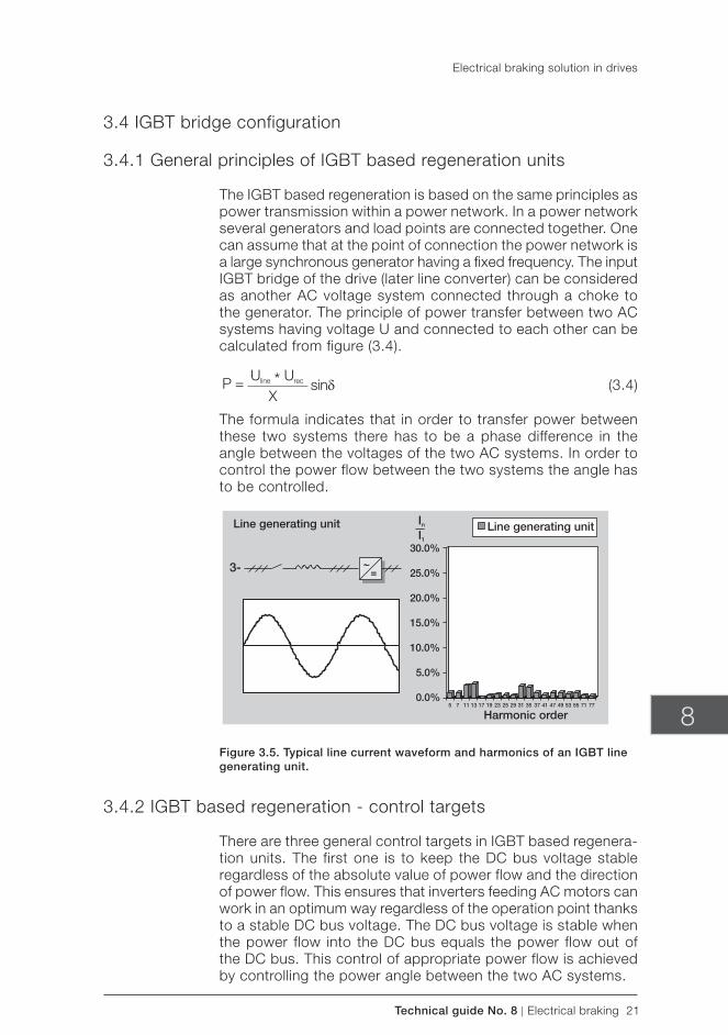
Technical guide No. 8 | Electrical braking 21
8
3.4 IGBT bridge configuration
3.4.1 General principles of IGBT based regeneration units
The IGBT based regeneration is based on the same principles as power transmission within a power network. In a power network several generators and load points are connected together. One can assume that at the point of connection the power network is a large synchronous generator having a fixed frequency. The input IGBT bridge of the drive (later line converter) can be considered as another AC voltage system connected through a choke to the generator. The principle of power transfer between two AC systems having voltage U and connected to each other can be calculated from figure (3.4).
(3.4)
The formula indicates that in order to transfer power between these two systems there has to be a phase difference in the angle between the voltages of the two AC systems. In order to control the power flow between the two systems the angle has to be controlled.
Figure 3.5. Typical line current waveform and harmonics of an IGBT line generating unit.
3.4.2 IGBT based regeneration - control targets
There are three general control targets in IGBT based regenera-tion units. The first one is to keep the DC bus voltage stable regardless of the absolute value of power flow and the direction of power flow. This ensures that inverters feeding AC motors can work in an optimum way regardless of the operation point thanks to a stable DC bus voltage. The DC bus voltage is stable when the power flow into the DC bus equals the power flow out of the DC bus. This control of appropriate power flow is achieved by controlling the power angle between the two AC systems.
Electrical braking solution in drives
Line generating unit Line generating unit
Harmonic order
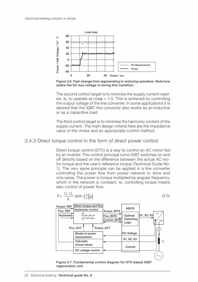
22 Electrical braking | Technical guide No. 8
Figure 3.6. Fast change from regenerating to motoring operation. Note how stable the DC bus voltage is during this transition.
The second control target is to minimise the supply current need-ed, ie, to operate at cosϕ = 1.0. This is achieved by controlling the output voltage of the line converter. In some applications it is desired that the IGBT line converter also works as an inductive or as a capacitive load.
The third control target is to minimise the harmonic content of the supply current. The main design criteria here are the impedance value of the choke and an appropriate control method.
3.4.3 Direct torque control in the form of direct power control
Direct torque control (DTC) is a way to control an AC motor fed by an inverter. The control principal turns IGBT switches on and off directly based on the difference between the actual AC mo-tor torque and the user’s reference torque (Technical Guide No. 1). The very same principle can be applied in a line converter controlling the power flow from power network to drive and vice versa. The power is torque multiplied by angular frequency, which in the network is constant, ie, controlling torque means also control of power flow.
(3.5)
Figure 3.7. Fundamental control diagram for DTC based IGBT regeneration unit.
Electrical braking solution in drives
Times / ms
DC Measurement
Power
Po
wer
/ k
W, V
olta
ge
/ 10
* V
Load step
Torque_REF Direct torque and fl uxHysteresis controlFlux_REF
Hysteresis
Torque_BITS
Flux_BITSControl_BITS
S1, S2, S3OptimalSwitchingLogic
ASICS
DC-Voltage
S1, S2, S3
Current
Flux_ACT Torque_ACT
Model of powertransmission
Calculateactual values
DC voltage control
L
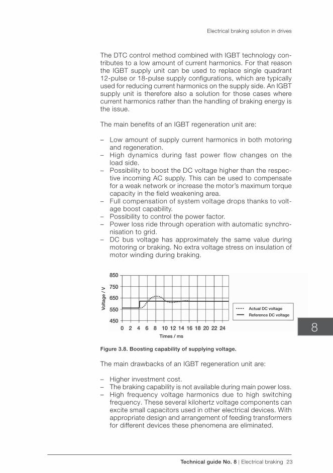
Technical guide No. 8 | Electrical braking 23
Times / ms
Volta
ge
/ V
8
The DTC control method combined with IGBT technology con-tributes to a low amount of current harmonics. For that reason the IGBT supply unit can be used to replace single quadrant 12-pulse or 18-pulse supply configurations, which are typically used for reducing current harmonics on the supply side. An IGBT supply unit is therefore also a solution for those cases where current harmonics rather than the handling of braking energy is the issue.
The main benefits of an IGBT regeneration unit are:
– Low amount of supply current harmonics in both motoring and regeneration.
– High dynamics during fast power flow changes on the load side.
– Possibility to boost the DC voltage higher than the respec-tive incoming AC supply. This can be used to compensate for a weak network or increase the motor’s maximum torque capacity in the field weakening area.
– Full compensation of system voltage drops thanks to volt-age boost capability.
– Possibility to control the power factor. – Power loss ride through operation with automatic synchro-
nisation to grid. – DC bus voltage has approximately the same value during
motoring or braking. No extra voltage stress on insulation of motor winding during braking.
Figure 3.8. Boosting capability of supplying voltage.
The main drawbacks of an IGBT regeneration unit are:
– Higher investment cost. – The braking capability is not available during main power loss. – High frequency voltage harmonics due to high switching
frequency. These several kilohertz voltage components can excite small capacitors used in other electrical devices. With appropriate design and arrangement of feeding transformers for different devices these phenomena are eliminated.
Electrical braking solution in drives
Actual DC voltage
Reference DC voltage
24 Electrical braking | Technical guide No. 8
When to use an IGBT regeneration unit:
– The braking is continuous or repeating regularly. – The braking power is very high. – When space savings can be achieved compared to the brak-
ing resistor solution. – When network harmonics limits are critical.
3.4.4 Dimensioning an IGBT regeneration unit
The supply current dimensioning of the IGBT unit is based on power needed. Let us assume that the motoring shaft power needed is 130 kW and braking power 100 kW. To dimension the IGBT supply unit the maximum value of motoring or braking power is selected, in this case 130 kW. The motor voltage is 400 V. The minimum value for the supplying network is 370 V.
In this case the voltage boost capability can be utilised; the DC bus voltage is raised to correspond to an AC voltage of 400 V. However, the required supply current is calculated based on the 370 level. Assuming that there are 5 percent system losses in the motor and drive, the total power needed from the grid is 136.5 kW. The supplying current can be calculated from the formula:
(3.6)
The IGBT regeneration unit is selected based solely on the cal-culated current value.
3.5 Common DC
When a process consists of several drives where one motor may need braking capability when others are operating in motoring mode, the common DC bus solution is a very effective way to reuse the mechanical energy. A common DC bus solution drive system consists of a separate supply rectifier converting AC to DC, and inverters feeding AC motors connected to the com-mon DC bus, ie, the DC bus is the channel to move braking energy from one motor to benefit the other motors. The basic configuration of the common DC bus arrangement can be seen from figure (3.9).
Electrical braking solution in drives
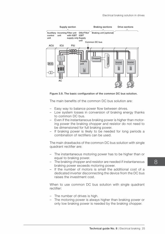
Technical guide No. 8 | Electrical braking 25
Supply section Braking sections Drive sections
Auxilliarycontrolunit
ACU ICU FIU
24 V
AC
Incomingunit
Filter unitwith IGBTsupply only
DSU/TSU/IGBTSupplyunit
Braking unit (optional)
Common DC bus
Supplyunit
Chopper
Res
isto
r
Inverter Inverter
8
Figure 3.9. The basic configuration of the common DC bus solution.
The main benefits of the common DC bus solution are:
– Easy way to balance power flow between drives. – Low system losses in conversion of braking energy thanks
to common DC bus. – Even if the instantaneous braking power is higher than motor-
ing power the braking chopper and resistor do not need to be dimensioned for full braking power.
– If braking power is likely to be needed for long periods a combination of rectifiers can be used.
The main drawbacks of the common DC bus solution with single quadrant rectifier are:
– The instantaneous motoring power has to be higher than or equal to braking power.
– The braking chopper and resistor are needed if instantaneous braking power exceeds motoring power.
– If the number of motors is small the additional cost of a dedicated inverter disconnecting the device from the DC bus raises the investment cost.
When to use common DC bus solution with single quadrant rectifier:
– The number of drives is high. – The motoring power is always higher than braking power or
only low braking power is needed by the braking chopper.
Electrical braking solution in drives
26 Electrical braking | Technical guide No. 8
e
Chapter 4 - Evaluating the life cycle cost of different forms of electrical braking
It has become increasingly important to evaluate the total life cycle cost when investing in energy saving products. The AC drive is used for controlling speed and torque. This basic func-tion of AC drives means savings in energy consumption in comparison to other control methods used. In pump and fan type applications braking is seldom needed. However, modern AC drives are increasingly being used in applications where a need for braking exists.
Several technical criteria are mentioned above. The following examines the economic factors for different electrical braking approaches.
4.1 Calculating the direct cost of energy
The direct cost of energy can be calculated based, for example, on the price of energy and the estimated brak-ing time and power per day. The price of energy varies from country to country, but a typical estimated price level of 0.05 euros per kilowatt-hour can be used. 1 euro ~ 1 USD. The annual cost of energy can be calculated from the formula:
(4.1)
For example, a 100 kW drive is running 8000 hours per year and braking with 50 kW average power for 5 minutes every hour, ie, 667 hours per year. The annual direct cost of braking energy is 1668 euros.
4.2 Evaluating the investment cost
The required investment objects needed for different braking methods vary. The following investment cost components should be evaluated.
Braking chopper:
– The additional investment cost of braking chopper and resistor plus the cost of additional space needed for those components.
– The investment cost of additional ventilation needed for the braking chopper.
Technical guide No. 8 | Electrical braking 27
8
Thyristor or IGBT based electrical braking:
– The additional investment cost of thyristor or IGBT regen-erative braking in respect to the same power drive without electrical braking capability.
Common DC bus:
– The additional investment cost of braking chopper and re-sistor including the space needed for those components if needed in a common DC bus solution.
– The investment cost difference between common DC bus solution and the respective single drive solution.
4.3 Calculating the life cycle cost
The life time cost calculation supports the purely economic deci-sion in making an investment. The price level of energy as well as the price of drives varies depending on the country, utility, size of company, interest ratio, the time the investment is used and the overall macroeconomic situation. The absolute values of prices given in the following examples are solely used to illustrate the calculation principles.
Case 1 - Occasional braking Consider the following application case:The continuous motoring power is 200 kW at a shaft speed of 1500 rpm. In the event of an emergency stop command the application is required to ramp down within 10 seconds. Based on the experience of the process an emergency stop happens once every month. The inertia J of the drive system is 122 kgm2. When the emergency stop is activated the load torque can be neglected.
Calculating the braking torque needed for the motor:
(4.2)
The typical torque value for a 200 kW, 1500 rpm motor is about 1200 Nm. A normal AC motor instantaneously controlled by an inverter can be run with torque at 200 percent of nominal value. To achieve higher torque values a proportionally higher motor current is also needed.
Evaluating the life cycle cost of different forms of electrical braking
28 Electrical braking | Technical guide No. 8
ee
The braking power is at its maximum at the beginning of the braking cycle.
(4.3)
The braking chopper and resistor have to withstand instante-nously the current for a power of 300 kW. The average braking power is calculated below.
(4.4)
(4.5)
Cost of resistor braking:The braking chopper needed is for a maximum braking power of 300 kW. If the drive has a power limitation function the braking resistor can be dimensioned according to the 150.3 kW. The ad-ditional cost of the braking chopper and resistor is 4000 euros.The braking resistor requires 0.4 m2 additional floor space. The cost of floor space is 500 euros/m2.
Due to the small total heating energy and emergency use of braking, the cost of additional cooling is considered negligible.
The total additional investment cost consists of:
– Braking chopper and resistor in cabinet, 4000 euros. – Floor space 0.4 m2 * 500 euros/m2, 200 euros.
The total cost of wasted energy during one braking is:
(4.6)In this case the cost of braking energy is negligible.
Cost of 4Q drive:The additional cost of a respective investment for electrical brak-ing with anti-parallel thyristor bridge in comparison with a drive with braking chopper is 7000 euros. As expected, the energy savings cannot be used as an argument to cover the additional investment required.
Evaluating the life cycle cost of different forms of electrical braking
Technical guide No. 8 | Electrical braking 29
e e
8
Case 2 - Crane application
Consider following application case: Crane with hoisting power of 100 kW. The crane needs full power on both the motoring and generating side. The longest hoist operation time can be 3 minutes. The average on duty time over one year for the hoist is 20 percent.
Cost of resistor braking:The braking chopper and resistor have to be dimensioned for continuous 100 kW braking due to the 3 minutes maximum brak-ing time. Typically the maximum braking chopper dimensioning is made for a braking time of 1 minute in 10 minutes. – Braking chopper and resistor in cabinet 7800 euros.
The mechanical construction of the crane allows having cabinets with braking chopper. No extra cost due to floor space.
It is assumed that for 50 percent of the duty time the crane operates on the generator side, ie, an average 2.4 h/day. The total cost of wasted energy is:
(4.7)
Cost of 4Q drive:The IGBT 4Q drive is recommended for crane applications.
The additional investment cost for electrical braking with IGBT input bridge in comparison to drive with braking chopper is 4000 euros.
The direct payback calculation indicates that an additional 4000 euros investment brings the same amount of energy savings during the first year of use.
Case 3 - Centrifuge application
Consider the following application case: Sugar Centrifuge with 6 pole motor 160 kW rating. The motor needs full torque for a period of 30 seconds to accelerate the charged basket to maximum speed of 1100 r/min, centrifuge then spins liquor off the charge for 30 seconds at high speed. Once the charge is dry motor decelerates the centrifuge as fast as possible to allow discharge and recharging.
Evaluating the life cycle cost of different forms of electrical braking

30 Electrical braking | Technical guide No. 8
In a batch cycle the charge, spin and discharge times are fixed, so the only opportunity to increase production is to increase the rates of acceleration and deceleration. This is achieved by us-ing an IGBT 4Q drive as the DC link voltage can be boosted for operation in the field weakening range (1000 to 1100 r/min). This can save around 3 seconds per cycle, therefore reducing cycle time from 110 seconds to 107 seconds. This allows an increase in throughput meaning that the productivity of the process is improved. The cost premium for IGBT is 10 percent.
Evaluating the life cycle cost of different forms of electrical braking
Technical guide No. 8 | Electrical braking 31
8
Chapter 5 - Symbols and Definitions
AC: Alternating current or voltage
B: Friction coefficient
C: Constant or coefficient
cosφ: Cosine of electrical angle between the fundamental voltage and current
DC: Direct current or voltage
DPF: Displacement power factor defined as cosφ1, where Ø1 is the phase angle between the fundamental frequency current drawn by the equipment and the supply voltage fundamental frequency component.
I: Current [Ampere, A]
J: Inertia [kgm2]
n: Rotation speed [revolutions per minute,rpm] P: Power [Watt, W]
PF: Power factor defined as PF = P/S (power/voltampere) = I1 / Is * DPF (With sinusoidal current PF is equal to DPF).
T: Torque (Newton meter, Nm)
t: Time
THD: Total harmonic distortion in the current is defined as
(5.1)
where I1 is the rms value of the fundamental frequency current. The THD in voltage may be calculated in a similar way.
U: Voltage [V]
W: Energy [Joule, J]
ω: Angular speed [radian/second, 1/s]
32 Electrical braking | Technical guide No. 8
AAC power 9
Bbraking chopper 13, 14, 16, 17, 18, 19, 25, 26, 27, 28, 29braking power 9, 10, 11, 12, 13, 14, 15, 16, 19, 24, 25, 28
Ccentrifuge 29common DC 24, 25, 27constant torque 7, 10, 14conveyors 7, 14cosφ 9, 20, 31crane 29
DDC injection braking 15DC power 9direct torque control 15, 22
Eenergy storage 16, 17
Ffans 14flux braking 15, 16four-quadrant 7friction 10, 11, 14, 31
Hharmonic distortion 20, 31
IIGBT 20, 21, 22, 23, 24, 27, 29, 30impedance 20, 22inertia 10, 11, 13, 27, 31inverter 7, 9, 15, 17, 22, 25, 27
Lline converter 21, 22
Nnatural braking 12, 13, 14
Oovervoltage control 17
Ppumps 14
Qquadratic torque 10, 14
Rrectifier 15, 16, 19, 24, 25
Ssingle quadrant 7, 10, 23, 25
Tthyristor bridge 19, 20, 28two-quadrant 7
Chapter 6 - Index

3A
FE64
3625
34 R
EV
B E
N 6
.5.2
011
#15
654
Contact us
For more information please contact your local ABB representative or visit:
www.abb.com/driveswww.abb.com/drivespartners
© Copyright 2011 ABB. All rights reserved. Specifications subject to change without notice.

Technical guide No. 9Guide to motion control drives
ABB drives

2 Motion control | Technical guide No. 9

Technical guide No. 9 | Motion control 3
9
© Copyright 2012 ABB. All rights reserved.
Specifications subject to change without notice.
3AFE68695201 REV B EN 8.6.2012
Technical guide No. 9Guide to motion control drives

4 Motion control | Technical guide No. 9
Technical guide No. 9 | Motion control 5
9
Contents
Chapter 1 - Introduction ............................................................................7
1.1. Motion control versus speed control .............................................71.2. Decentralized or centralized control ..............................................81.3. Comparison between decentralized and centralized systems .........91.4. Main functional parts of machine ..................................................91.5. Machine components ................................................................10
Chapter 2 - Drive and motor combination ...............................................11
2.1. Brush-type DC ..........................................................................112.2. Brushless DC ...........................................................................112.3. Asynchronous servo ..................................................................122.4. Synchronous servo ...................................................................13
Chapter 3 - Synchronous technology ......................................................14
3.1. Measuring performance .............................................................143.2. How synchronous servo motors differ from induction motors .......15
Chapter 4 - Synchronous servo motor – principle of operation ...............16
4.1. Special conditions during start up ..............................................174.2. Traditional speed and current control ..........................................17
Chapter 5 - Typical servo motors data.....................................................19
5.1. Torque constant.........................................................................195.2. Back EMF .................................................................................195.3. Torque curve .............................................................................195.4. Typical motor data .....................................................................20
Chapter 6 - Feedback devices .................................................................21
6.1. Resolver ....................................................................................216.2. Incremental encoders ................................................................226.3. SinCos encoder .........................................................................22
Chapter 7 - Motion control ......................................................................24
7.1. General .....................................................................................247.2. Motion control – basic blocks .....................................................247.3. Motion control formulas and profiles ...........................................257.4. Motion profile ...........................................................................257.5. Position interpolator ...................................................................25

6 Motion control | Technical guide No. 9
Chapter 8 - Typical motion functions .......................................................26
8.1. Positioning ................................................................................268.2. Absolute positioning ..................................................................268.3. Relative positioning ....................................................................268.4. Synchronization .........................................................................278.5. Rollover axis ..............................................................................288.6. Dynamic limiter ..........................................................................288.7. CAM disk ..................................................................................288.8. Homing .....................................................................................298.9. Cyclic corrections ......................................................................318.10. Encoder gear functions ............................................................328.11. Virtual master/axis ...................................................................33
Chapter 9 - Application examples, distributed control ............................34
9.1. Cyclic correction for material handling. .......................................349.2. Constant gap maintaining ..........................................................359.3. Cut to length .............................................................................369.4. Rotary knife ...............................................................................379.5. Cyclic correction, packing application .........................................389.6. Flying shear, angled ...................................................................399.7. Flying shear, parallel ...................................................................409.8. Lathe ........................................................................................419.9. Material filling ............................................................................429.10. Slitter ......................................................................................439.11. Picking and stacking ................................................................449.12. Warehouse automation ............................................................459.13. Winding ...................................................................................469.14. Wrapping ................................................................................47
Chapter 10 - Motion control – *Glossary of terms ...................................48
Chapter 11 - Index ...................................................................................62
Technical guide No. 9 | Motion control 7
9
Chapter 1 - Introduction
This guide aims to give users an overview of high performance drives and motion control. Although written in a simple style to make it relevant to most applications, readers need to have a basic understanding of AC drive technology to benefit from this guide.
When considering a motion control application it is important to consider all elements in the system including drives, motors, mechanical power transmission components, software, etc.
A high performance system has one or more of the following characteristics:
– high dynamic performance – high accuracy reference following and repeatability – high accuracy motion functions – capability to run different motor types
1.1. Motion control versus speed control
Standard variable speed drives normally control the motor by giving a speed command. The system typically has no feedback and speed reference is preset speeds, 0 to 10 Volts, 4 to 20 mA, or fieldbus.
With motion control, there is always feedback of the real position. This is compared to the reference value and the difference is cor-rected continuously by the motion controller’s profile generator.
Positioning is a good example that highlights this difference. If a standard drive is used for positioning, the motor normally runs at high speed, then decelerates to a lower speed and stops. Alternatively, the drive can follow an analog signal. Either way, no reference profile is followed, compared for errors or corrected. This results in low accuracy.
Accuracy can be improved if the controller is a high performance motion controller but in this case, the dynamics and the sample time (generally several milliseconds) of the standard drive become limiting factors.
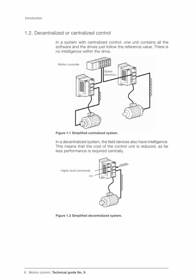
8 Motion control | Technical guide No. 9
Introduction
1.2. Decentralized or centralized control
In a system with centralized control, one unit contains all the software and the drives just follow the reference value. There is no intelligence within the drive.
Figure 1.1 Simplified centralized system.
In a decentralized system, the field devices also have intelligence. This means that the cost of the control unit is reduced, as far less performance is required centrally.
Figure 1.2 Simplified decentralized system.
Motion controller
Speed reference
Higher level commands
I/O
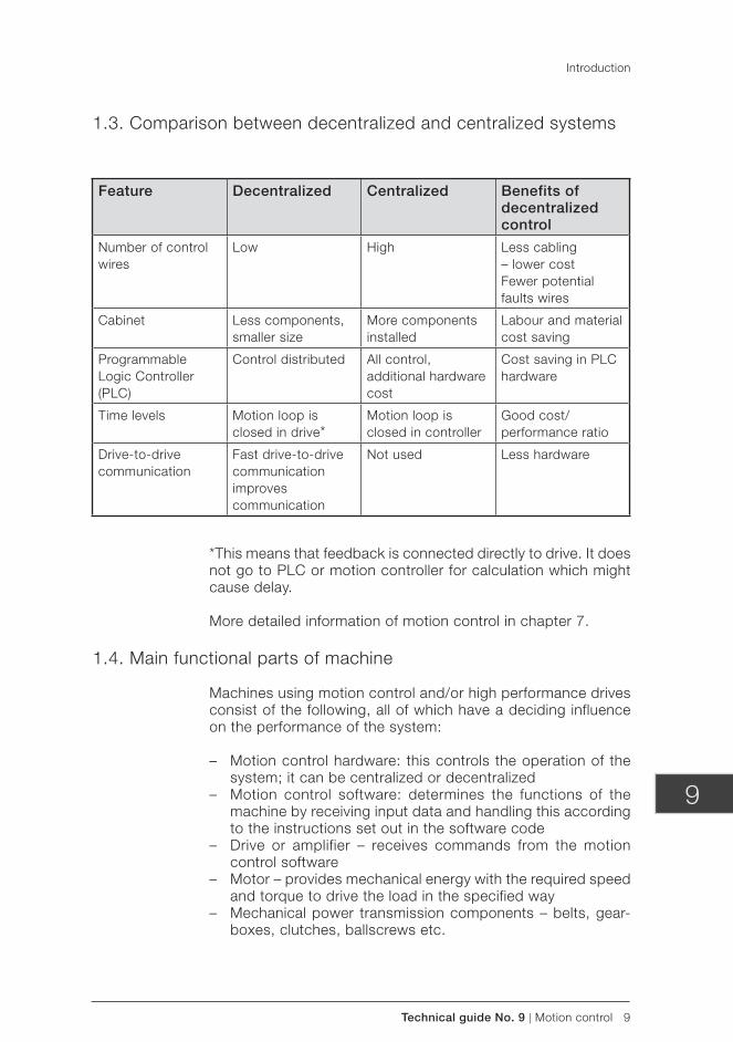
Technical guide No. 9 | Motion control 9
9
Introduction
1.3. Comparison between decentralized and centralized systems
*This means that feedback is connected directly to drive. It does not go to PLC or motion controller for calculation which might cause delay.
More detailed information of motion control in chapter 7.
1.4. Main functional parts of machine
Machines using motion control and/or high performance drives consist of the following, all of which have a deciding influence on the performance of the system:
– Motion control hardware: this controls the operation of the system; it can be centralized or decentralized
– Motion control software: determines the functions of the machine by receiving input data and handling this according to the instructions set out in the software code
– Drive or amplifier – receives commands from the motion control software
– Motor – provides mechanical energy with the required speed and torque to drive the load in the specified way
– Mechanical power transmission components – belts, gear-boxes, clutches, ballscrews etc.
Feature Decentralized Centralized Benefits of decentralized control
Number of control wires
Low High Less cabling– lower costFewer potential faults wires
Cabinet Less components, smaller size
More components installed
Labour and material cost saving
Programmable Logic Controller ( PLC)
Control distributed All control, additional hardware cost
Cost saving in PLC hardware
Time levels Motion loop is closed in drive*
Motion loop is closed in controller
Good cost/ performance ratio
Drive-to-drive communication
Fast drive-to-drive communication improves communication
Not used Less hardware
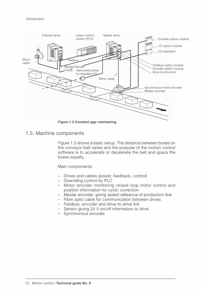
10 Motion control | Technical guide No. 9
Figure 1.3 Constant gap maintaining.
1.5. Machine components
Figure 1.3 shows a basic setup. The distance between boxes on the conveyor belt varies and the purpose of the motion control software is to accelerate or decelerate the belt and space the boxes equally.
Main components:
– Drives and cables (power, feedback, control) – Overriding control by PLC – Motor encoder monitoring closed loop motor control and
position information for cyclic correction – Master encoder, giving speed reference of production line – Fibre optic cable for communication between drives – Fieldbus, encoder and drive-to-drive link – Sensor giving 24 V on/off information to drive – Synchronous encoder
Introduction
Follower drive Upper control system ( PLC)
Master drive
Motorcable
Fieldbus
Master/follower Fibres Hard wired probe
for standard I/O
Motor cable
Synchronous motor encoderMaster encoder
Fieldbus option module Encoder option moduleDrive-to-drive link
Encoder option module
I/O option module
I/O extension
Technical guide No. 9 | Motion control 11
9
Chapter 2 - Drive and motor combination
The drive and motor are normally supplied as a package to suit the application. The main drive, motor types and features are described here.
2.1. Brush-type DC
The basic principle is the same as in industrial high power DC drives, the main difference being that there is no magnetizing circuit. Instead, the motor carries permanent magnets on the stator side. Rotor current and voltage is supplied by brushes and a commutator.
Normally, it is not possible to use the supply voltage. Instead, a transformer is used to reduce the voltage. Some drives have a rectifier circuit, while others need an external voltage rectifier.
The electronics are relatively simple and only speed feedback is required for the speed controller. Brush-type DC drives is one of a small number of control platforms that actually use a tacho as a feedback device for the speed reference.
When this type of drive and motor combination is used in mo-tion control, a pulse encoder is quite often fitted to the motor shaft. Pulses are sent to the motion controller for calculating the position.
The benefit of brush-type technology is the simple and inexpen-sive controller. The drawback is that the commutator and the brushes are mechanical components and have limited lifetime. Especially in applications where the motor always stops in the same position, the commutator gets worn in one particular place, thereby reducing its life even more.
The main players in the drives industry do not use this technol-ogy anymore. Typically these kinds of products are based on old analogue platform.
2.2. Brushless DC
The power circuit of a brushless DC servo drive is similar to that of an AC drive. Input current is rectified and filtered in a diode bridge with associated DC-link capacitance. The inverter unit consists of six power devices.
However, with a brushless DC drive the output voltage is not modulated to form sinusoidal current, unlike in an AC drive.
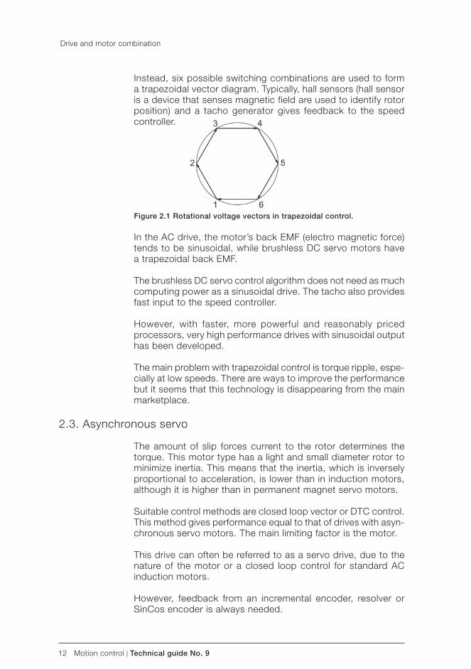
12 Motion control | Technical guide No. 9
Instead, six possible switching combinations are used to form a trapezoidal vector diagram. Typically, hall sensors (hall sensor is a device that senses magnetic field are used to identify rotor position) and a tacho generator gives feedback to the speed controller.
Figure 2.1 Rotational voltage vectors in trapezoidal control.
In the AC drive, the motor’s back EMF (electro magnetic force) tends to be sinusoidal, while brushless DC servo motors have a trapezoidal back EMF.
The brushless DC servo control algorithm does not need as much computing power as a sinusoidal drive. The tacho also provides fast input to the speed controller.
However, with faster, more powerful and reasonably priced processors, very high performance drives with sinusoidal output has been developed.
The main problem with trapezoidal control is torque ripple, espe-cially at low speeds. There are ways to improve the performance but it seems that this technology is disappearing from the main marketplace.
2.3. Asynchronous servo
The amount of slip forces current to the rotor determines the torque. This motor type has a light and small diameter rotor to minimize inertia. This means that the inertia, which is inversely proportional to acceleration, is lower than in induction motors, although it is higher than in permanent magnet servo motors.
Suitable control methods are closed loop vector or DTC control. This method gives performance equal to that of drives with asyn-chronous servo motors. The main limiting factor is the motor.
This drive can often be referred to as a servo drive, due to the nature of the motor or a closed loop control for standard AC induction motors.
However, feedback from an incremental encoder, resolver or SinCos encoder is always needed.
Drive and motor combination

Technical guide No. 9 | Motion control 13
9
2.4. Synchronous servo
This type of motor is quite often called AC brushless servo. Syn-chronous servo motors have a rotor with permanent magnets and a stator for three phase supply. The rotor has very low inertia and can achieve fast dynamic performance. The motor operation is synchronous and the feedback device has to be able to deliver continuous position and speed information to the amplifier.
In chapter 3 (page 15) the AC synchronous servo motor is ex-plained in more detailes.
Drive and motor combination
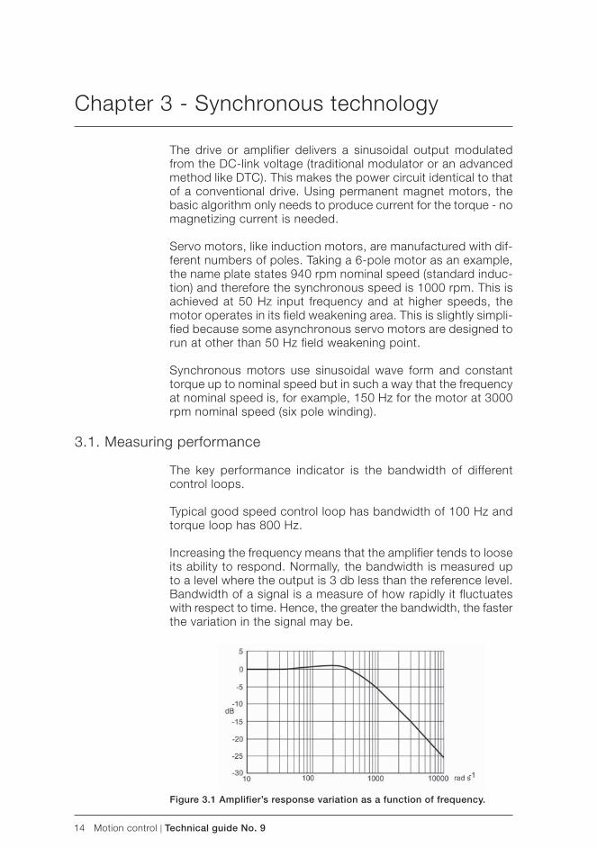
14 Motion control | Technical guide No. 9
Chapter 3 - Synchronous technology
The drive or amplifier delivers a sinusoidal output modulated from the DC-link voltage (traditional modulator or an advanced method like DTC). This makes the power circuit identical to that of a conventional drive. Using permanent magnet motors, the basic algorithm only needs to produce current for the torque - no magnetizing current is needed.
Servo motors, like induction motors, are manufactured with dif-ferent numbers of poles. Taking a 6-pole motor as an example, the name plate states 940 rpm nominal speed (standard induc-tion) and therefore the synchronous speed is 1000 rpm. This is achieved at 50 Hz input frequency and at higher speeds, the motor operates in its field weakening area. This is slightly simpli-fied because some asynchronous servo motors are designed to run at other than 50 Hz field weakening point.
Synchronous motors use sinusoidal wave form and constant torque up to nominal speed but in such a way that the frequency at nominal speed is, for example, 150 Hz for the motor at 3000 rpm nominal speed (six pole winding).
3.1. Measuring performance
The key performance indicator is the bandwidth of different control loops.
Typical good speed control loop has bandwidth of 100 Hz and torque loop has 800 Hz.
Increasing the frequency means that the amplifier tends to loose its ability to respond. Normally, the bandwidth is measured up to a level where the output is 3 db less than the reference level. Bandwidth of a signal is a measure of how rapidly it fluctuates with respect to time. Hence, the greater the bandwidth, the faster the variation in the signal may be.
Figure 3.1 Amplifier’s response variation as a function of frequency.
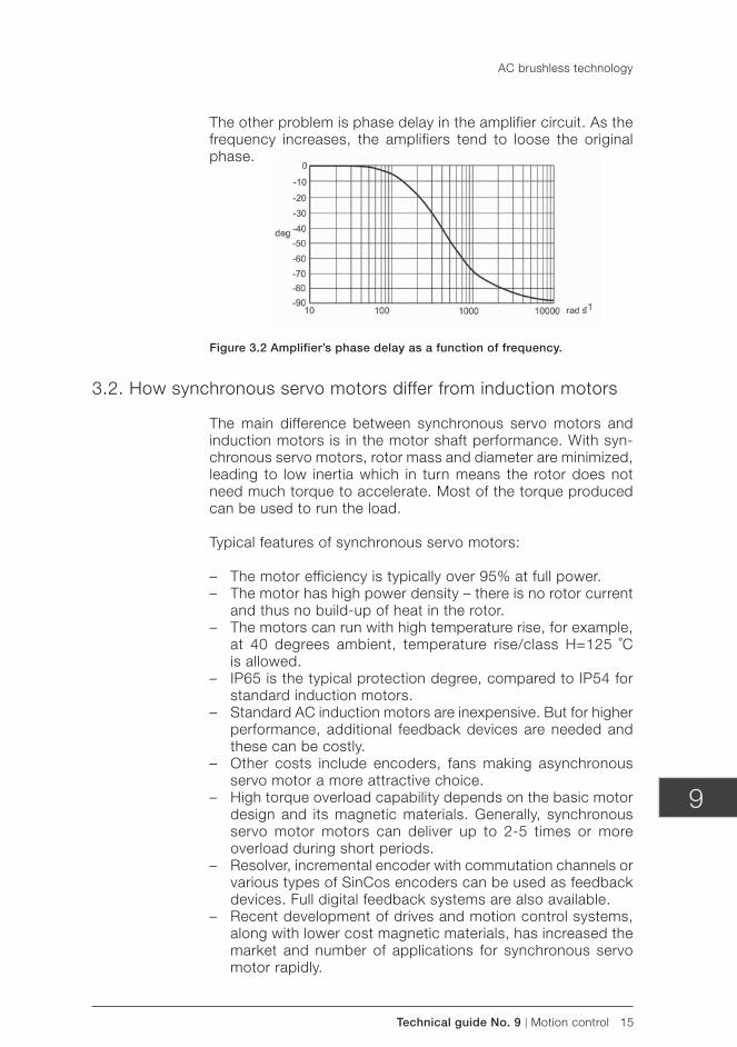
Technical guide No. 9 | Motion control 15
9
The other problem is phase delay in the amplifier circuit. As the frequency increases, the amplifiers tend to loose the original phase.
Figure 3.2 Amplifier’s phase delay as a function of frequency.
3.2. How synchronous servo motors differ from induction motors
The main difference between synchronous servo motors and induction motors is in the motor shaft performance. With syn-chronous servo motors, rotor mass and diameter are minimized, leading to low inertia which in turn means the rotor does not need much torque to accelerate. Most of the torque produced can be used to run the load.
Typical features of synchronous servo motors:
– The motor efficiency is typically over 95% at full power. – The motor has high power density – there is no rotor current
and thus no build-up of heat in the rotor. – The motors can run with high temperature rise, for example,
at 40 degrees ambient, temperature rise/class H=125 ˚C is allowed.
– IP65 is the typical protection degree, compared to IP54 for standard induction motors.
– Standard AC induction motors are inexpensive. But for higher performance, additional feedback devices are needed and these can be costly.
– Other costs include encoders, fans making asynchronous servo motor a more attractive choice.
– High torque overload capability depends on the basic motor design and its magnetic materials. Generally, synchronous servo motor motors can deliver up to 2-5 times or more overload during short periods.
– Resolver, incremental encoder with commutation channels or various types of SinCos encoders can be used as feedback devices. Full digital feedback systems are also available.
– Recent development of drives and motion control systems, along with lower cost magnetic materials, has increased the market and number of applications for synchronous servo motor rapidly.
AC brushless technology
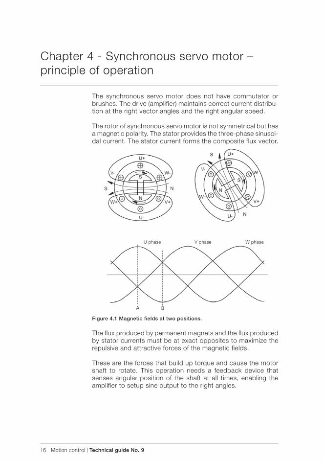
16 Motion control | Technical guide No. 9
Chapter 4 - Synchronous servo motor – principle of operation
The synchronous servo motor does not have commutator or brushes. The drive (amplifier) maintains correct current distribu-tion at the right vector angles and the right angular speed.
The rotor of synchronous servo motor is not symmetrical but has a magnetic polarity. The stator provides the three- phase sinusoi-dal current. The stator current forms the composite flux vector.
U phase V phase W phase
Figure 4.1 Magnetic fields at two positions.
The flux produced by permanent magnets and the flux produced by stator currents must be at exact opposites to maximize the repulsive and attractive forces of the magnetic fields.
These are the forces that build up torque and cause the motor shaft to rotate. This operation needs a feedback device that senses angular position of the shaft at all times, enabling the amplifier to setup sine output to the right angles.
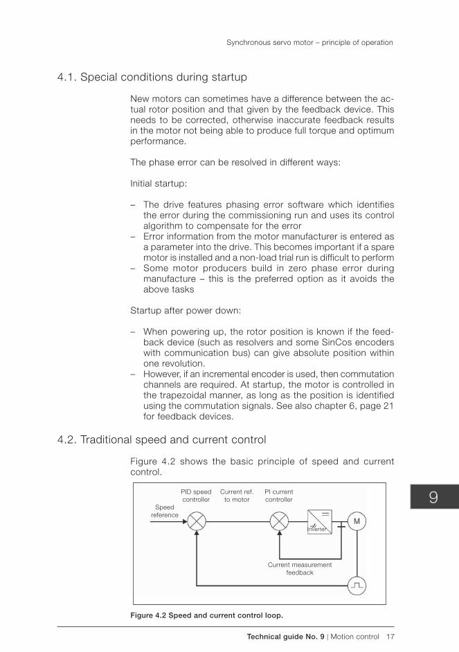
Technical guide No. 9 | Motion control 17
9
4.1. Special conditions during startup
New motors can sometimes have a difference between the ac-tual rotor position and that given by the feedback device. This needs to be corrected, otherwise inaccurate feedback results in the motor not being able to produce full torque and optimum performance.
The phase error can be resolved in different ways:
Initial startup:
– The drive features phasing error software which identifies the error during the commissioning run and uses its control algorithm to compensate for the error
– Error information from the motor manufacturer is entered as a parameter into the drive. This becomes important if a spare motor is installed and a non-load trial run is difficult to perform
– Some motor producers build in zero phase error during manufacture – this is the preferred option as it avoids the above tasks
Startup after power down:
– When powering up, the rotor position is known if the feed-back device (such as resolvers and some SinCos encoders with communication bus) can give absolute position within one revolution.
– However, if an incremental encoder is used, then commutation channels are required. At startup, the motor is controlled in the trapezoidal manner, as long as the position is identified using the commutation signals. See also chapter 6, page 21 for feedback devices.
4.2. Traditional speed and current control
Figure 4.2 shows the basic principle of speed and current control.
Synchronous servo motor – principle of operation
PID speed controller
PI current controller
Current ref. to motor
Inverter
Current measurement feedback
Speed reference
Figure 4.2 Speed and current control loop.

18 Motion control | Technical guide No. 9
The role of the servo drive or amplifier is to make sure that the motor speed and torque follows the reference value. The motor´s feedback gives actual speed to the speed controller. The speed controller is typically a PID controller comparing reference and feedback signals.
The error signal is passed to the current controller. The current controller, typically a PI amplifier, sets up the correct current so that the right torque is available to keep the speed at the refer-ence level.
Synchronous servo motor – principle of operation
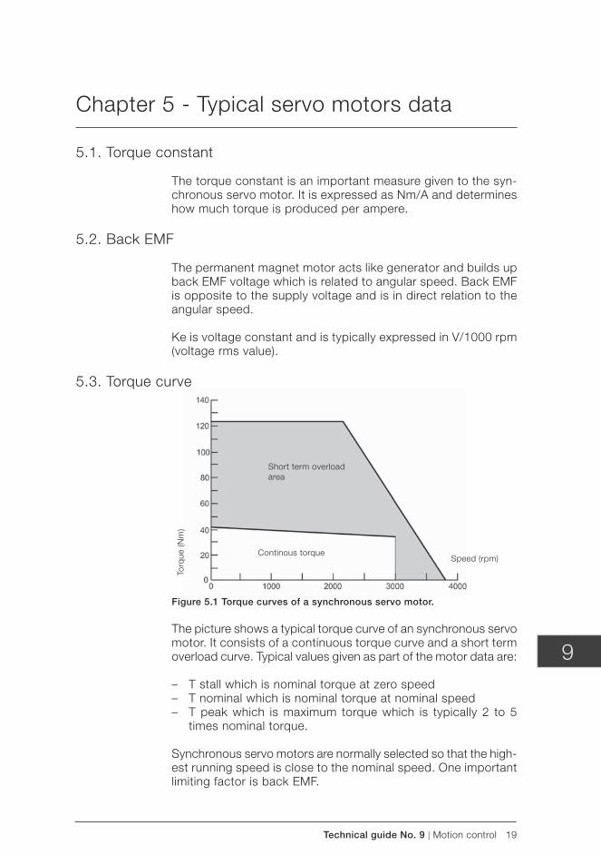
Technical guide No. 9 | Motion control 19
9
Chapter 5 - Typical servo motors data
5.1. Torque constant
The torque constant is an important measure given to the syn-chronous servo motor. It is expressed as Nm/A and determines how much torque is produced per ampere.
5.2. Back EMF
The permanent magnet motor acts like generator and builds up back EMF voltage which is related to angular speed. Back EMF is opposite to the supply voltage and is in direct relation to the angular speed.
Ke is voltage constant and is typically expressed in V/1000 rpm (voltage rms value).
5.3. Torque curve
Short term overload area
Continous torqueSpeed (rpm)
Torq
ue (N
m)
Figure 5.1 Torque curves of a synchronous servo motor.
The picture shows a typical torque curve of an synchronous servo motor. It consists of a continuous torque curve and a short term overload curve. Typical values given as part of the motor data are:
– T stall which is nominal torque at zero speed – T nominal which is nominal torque at nominal speed – T peak which is maximum torque which is typically 2 to 5
times nominal torque.
Synchronous servo motors are normally selected so that the high-est running speed is close to the nominal speed. One important limiting factor is back EMF.
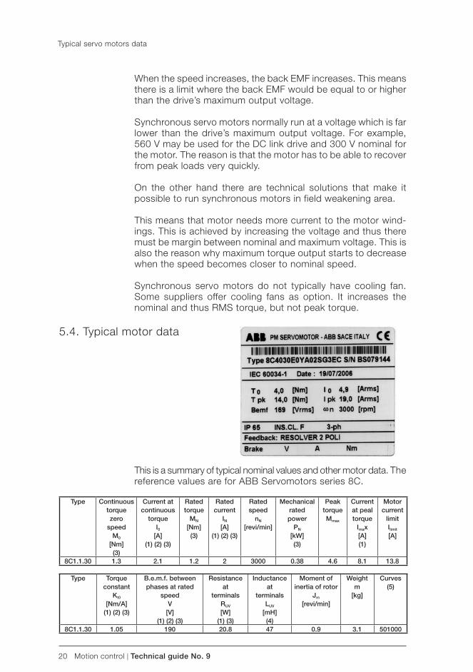
20 Motion control | Technical guide No. 9
When the speed increases, the back EMF increases. This means there is a limit where the back EMF would be equal to or higher than the drive’s maximum output voltage.
Synchronous servo motors normally run at a voltage which is far lower than the drive’s maximum output voltage. For example, 560 V may be used for the DC link drive and 300 V nominal for the motor. The reason is that the motor has to be able to recover from peak loads very quickly.
On the other hand there are technical solutions that make it possible to run synchronous motors in field weakening area.
This means that motor needs more current to the motor wind-ings. This is achieved by increasing the voltage and thus there must be margin between nominal and maximum voltage. This is also the reason why maximum torque output starts to decrease when the speed becomes closer to nominal speed.
Synchronous servo motors do not typically have cooling fan.Some suppliers offer cooling fans as option. It increases the nominal and thus RMS torque, but not peak torque.
5.4. Typical motor data
Type Continuoustorque zero
speedM0
[Nm](3)
Current atcontinuous
torqueI0
[A](1) (2) (3)
Rated torque
MN
[Nm](3)
Rated current
IN
[A](1) (2) (3)
Rated speed
nN
[revi/min]
Mechanicalrated power
PN
[kW](3)
Peak torqueMmax
Current at peal torque
Imax[A](1)
Motor current
limitIlimit
[A]
8C1.1.30 1.3 2.1 1.2 2 3000 0.38 4.6 8.1 13.8
Type Torque constant
Kt0
[Nm/A](1) (2) (3)
B.e.m.f. between phases at rated
speedV
[V](1) (2) (3)
Resistance at
terminalsRUV
[W](1) (3)
Inductance at
terminalsLUV
[mH](4)
Moment of inertia of rotor
Jm
[revi/min]
Weightm
[kg]
Curves(5)
8C1.1.30 1.05 190 20.8 47 0.9 3.1 501000
Typical servo motors data
This is a summary of typical nominal values and other motor data. The reference values are for ABB Servomotors series 8C.
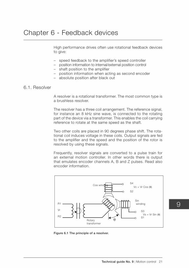
Technical guide No. 9 | Motion control 21
9
Chapter 6 - Feedback devices
High performance drives often use rotational feedback devices to give:
– speed feedback to the amplifier’s speed controller – position information to internal/external position control – shaft position to the amplifier – position information when acting as second encoder – absolute position after black out
6.1. Resolver
A resolver is a rotational transformer. The most common type is a brushless resolver.
The resolver has a three coil arrangement. The reference signal, for instance an 8 kHz sine wave, is connected to the rotating part of the device via a transformer. This enables the coil carrying reference to rotate at the same speed as the shaft.
Two other coils are placed in 90 degrees phase shift. The rota-tional coil induces voltage in these coils. Output signals are fed to the amplifier and the speed and the position of the rotor is resolved by using these signals.
Frequently, resolver signals are converted to a pulse train for an external motion controller. In other words there is output that emulates encoder channels A, B and Z pulses. Read also encoder information.
Cos windingS4
S2
S3
S1Vs = Vr Sin (θ)
Vc = Vr Cos (θ)
Sin winding
Rotarytransformer
R1
Vr
R2
Figure 6.1 The principle of a resolver.
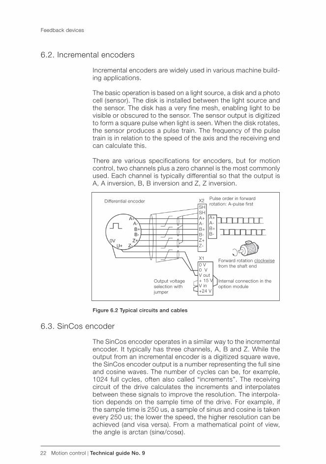
22 Motion control | Technical guide No. 9
6.2. Incremental encoders
Incremental encoders are widely used in various machine build-ing applications.
The basic operation is based on a light source, a disk and a photo cell (sensor). The disk is installed between the light source and the sensor. The disk has a very fine mesh, enabling light to be visible or obscured to the sensor. The sensor output is digitized to form a square pulse when light is seen. When the disk rotates, the sensor produces a pulse train. The frequency of the pulse train is in relation to the speed of the axis and the receiving end can calculate this.
There are various specifications for encoders, but for motion control, two channels plus a zero channel is the most commonly used. Each channel is typically differential so that the output is A, A inversion, B, B inversion and Z, Z inversion.
Differential encoder
Figure 6.2 Typical circuits and cables
X2SHSHA+A-B+B-Z+Z-
X10 V0 VV out+ 15 VV in+24 V
Pulse order in forward rotation: A-pulse first
A+A-B+B-
Forward rotation clockwise from the shaft end
Internal connection in the option module
Output voltage selection with jumper
Feedback devices
6.3. SinCos encoder
The SinCos encoder operates in a similar way to the incremental encoder. It typically has three channels, A, B and Z. While the output from an incremental encoder is a digitized square wave, the SinCos encoder output is a number representing the full sine and cosine waves. The number of cycles can be, for example, 1024 full cycles, often also called “increments”. The receiving circuit of the drive calculates the increments and interpolates between these signals to improve the resolution. The interpola-tion depends on the sample time of the drive. For example, if the sample time is 250 us, a sample of sinus and cosine is taken every 250 us; the lower the speed, the higher resolution can be achieved (and visa versa). From a mathematical point of view, the angle is arctan (sinα/cosα).
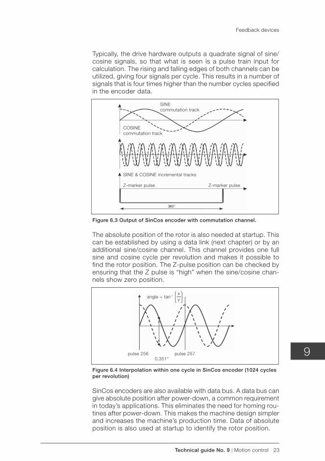
Technical guide No. 9 | Motion control 23
9
Feedback devices
SINEcommutation track
Typically, the drive hardware outputs a quadrate signal of sine/cosine signals, so that what is seen is a pulse train input for calculation. The rising and falling edges of both channels can be utilized, giving four signals per cycle. This results in a number of signals that is four times higher than the number cycles specified in the encoder data.
Figure 6.3 Output of SinCos encoder with commutation channel.
The absolute position of the rotor is also needed at startup. This can be established by using a data link (next chapter) or by an additional sine/cosine channel. This channel provides one full sine and cosine cycle per revolution and makes it possible to find the rotor position. The Z-pulse position can be checked by ensuring that the Z pulse is “high” when the sine/cosine chan-nels show zero position.
Figure 6.4 Interpolation within one cycle in SinCos encoder (1024 cycles per revolution)
SinCos encoders are also available with data bus. A data bus can give absolute position after power-down, a common requirement in today’s applications. This eliminates the need for homing rou-tines after power-down. This makes the machine design simpler and increases the machine’s production time. Data of absolute position is also used at startup to identify the rotor position.
COSINEcommutation track
SINE & COSINE incremental tracks
Z-marker pulse Z-marker pulse
angle = tan-1xy
pulse 256 pulse 2570,351°
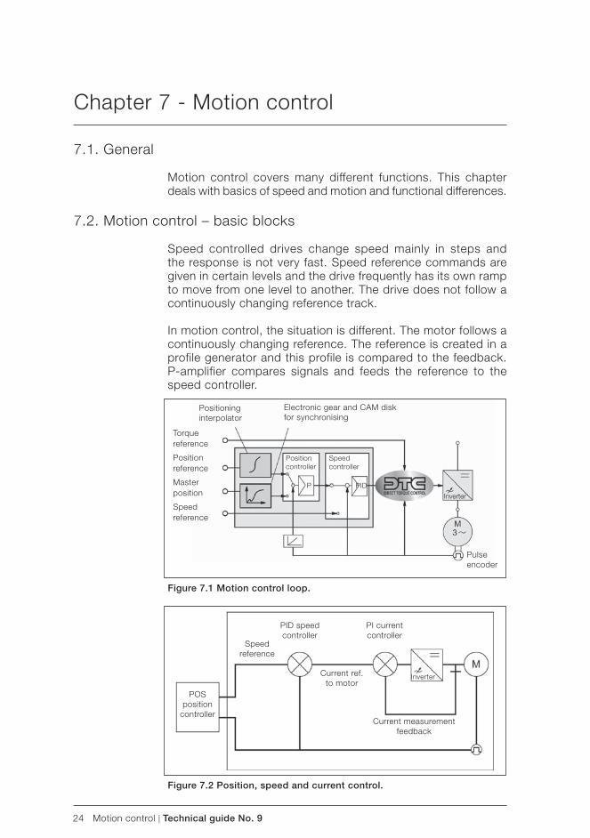
24 Motion control | Technical guide No. 9
Chapter 7 - Motion control
7.1. General
Motion control covers many different functions. This chapter deals with basics of speed and motion and functional differences.
7.2. Motion control – basic blocks
Speed controlled drives change speed mainly in steps and the response is not very fast. Speed reference commands are given in certain levels and the drive frequently has its own ramp to move from one level to another. The drive does not follow a continuously changing reference track.
In motion control, the situation is different. The motor follows a continuously changing reference. The reference is created in a profile generator and this profile is compared to the feedback. P-amplifier compares signals and feeds the reference to the speed controller.
Positioning interpolator
Electronic gear and CAM disk for synchronising
Torquereference
Positionreference
Master position
Speedreference
Position controller
Speed controller
P PID
Pulse encoder
Inverter
Figure 7.1 Motion control loop.
Figure 7.2 Position, speed and current control.
PID speed controller
PI current controller
Current ref. to motor
Inverter
Current measurement feedback
POS position
controller
Speed reference
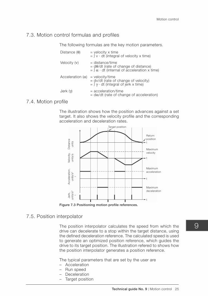
Technical guide No. 9 | Motion control 25
9
7.3. Motion control formulas and profiles
The following formulas are the key motion parameters.
Target position
Return positiont
Maximum velocity
t
Maximum acceleration
t
Maximum deceleration
t
Jerk
,un
its/s
3
3
Acc
eler
atio
n,un
its/s
2
2
Velo
city
,un
its/s
Dis
tanc
eun
its
7.4. Motion profile
The illustration shows how the position advances against a set target. It also shows the velocity profile and the corresponding acceleration and deceleration rates.
Figure 7.3 Positioning motion profile references.
7.5. Position interpolator
The position interpolator calculates the speed from which the drive can decelerate to a stop within the target distance, using the defined deceleration reference. The calculated speed is used to generate an optimized position reference, which guides the drive to its target position. The illustration refered to shows how the position interpolator generates a position reference.
The typical parameters that are set by the user are – Acceleration – Run speed – Deceleration – Target position
Motion control
Distance (θ) = velocity x time = ∫ v · dt (integral of velocity x time)
Velocity (ν) = distance/time = dθ/dt (rate of change of distance) = ∫ α · dt (internal of acceleration x time)
Acceleration (α) = velocity/time = dv/dt (rate of change of velocity) = ∫ γ · dt (integral of jerk x time)
Jerk (γ) = acceleration/time = dα/dt (rate of change of acceleration)
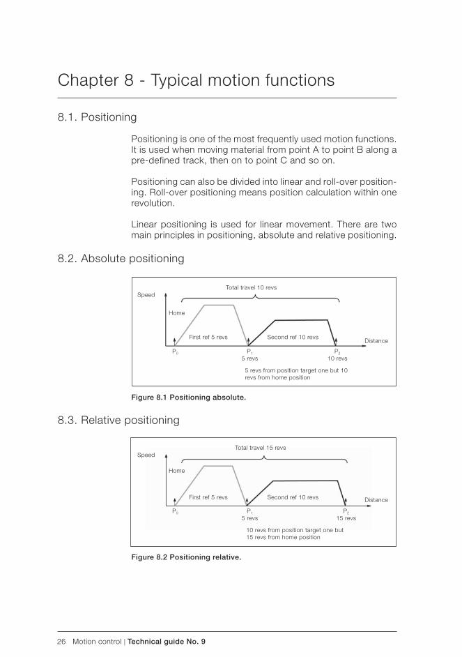
26 Motion control | Technical guide No. 9
Chapter 8 - Typical motion functions
8.1. Positioning
Positioning is one of the most frequently used motion functions. It is used when moving material from point A to point B along a pre-defined track, then on to point C and so on.
Positioning can also be divided into linear and roll-over position-ing. Roll-over positioning means position calculation within one revolution.
Linear positioning is used for linear movement. There are two main principles in positioning, absolute and relative positioning.
8.2. Absolute positioning
Figure 8.1 Positioning absolute.
8.3. Relative positioning
Speed
Distance
Total travel 10 revs
First ref 5 revs Second ref 10 revs
5 revs from position target one but 10 revs from home position
P1
5 revs
Home
Figure 8.2 Positioning relative.
SpeedTotal travel 15 revs
First ref 5 revs Second ref 10 revs
10 revs from position target one but 15 revs from home position
P2
10 revsP0
Distance
Home
P1
5 revsP2
15 revsP0
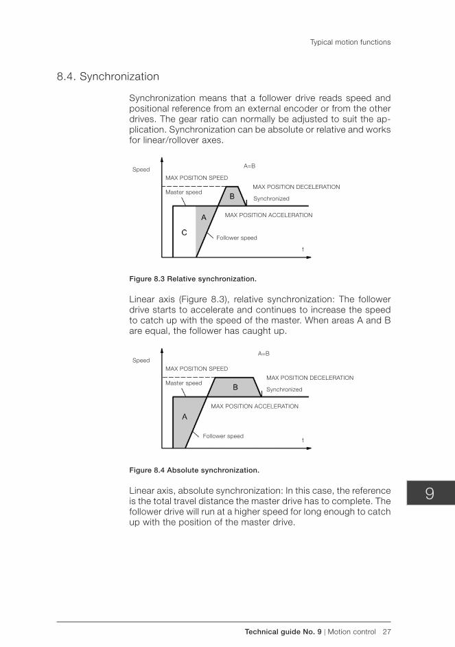
Technical guide No. 9 | Motion control 27
9
8.4. Synchronization
Synchronization means that a follower drive reads speed and positional reference from an external encoder or from the other drives. The gear ratio can normally be adjusted to suit the ap-plication. Synchronization can be absolute or relative and works for linear/rollover axes.
Speed
Figure 8.3 Relative synchronization.
Linear axis (Figure 8.3), relative synchronization: The follower drive starts to accelerate and continues to increase the speed to catch up with the speed of the master. When areas A and B are equal, the follower has caught up.
MAX POSITION SPEED
Master speed
Follower speed
A=B
MAX POSITION DECELERATION
Synchronized
t
MAX POSITION ACCELERATION
SpeedMAX POSITION SPEED
Master speed
Follower speed
A=B
MAX POSITION DECELERATION
Synchronized
t
MAX POSITION ACCELERATION
Figure 8.4 Absolute synchronization.
Linear axis, absolute synchronization: In this case, the reference is the total travel distance the master drive has to complete. The follower drive will run at a higher speed for long enough to catch up with the position of the master drive.
Typical motion functions
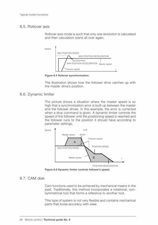
28 Motion control | Technical guide No. 9
Typical motion functions
8.5. Rollover axis
Rollover axis mode is such that only one revolution is calculated and then calculation starts all over again.
Speed
MAX POSITION SPEED
Master speed
Follower speed
MAX POSITION DECELERATION
Synchronized
t
MAX POSITION ACCELERATION
Figure 8.6 Dynamic limiter controls follower’s speed.
8.7. CAM disk
Cam functions used to be achieved by mechanical means in the past. Traditionally, this method incorporates a rotational, non-symmetrical tool that forms a reference to another tool.
This type of system is not very flexible and contains mechanical parts that loose accuracy with wear.
Speed
MAX POSITION SPEED
Master speed
Follower speed
POSITION DECELERATION
STOP
t
POSITION SPEED
Master speed
A=B
Figure 8.5 Rollover synchronization.
The illustration shows how the follower drive catches up with the master drive’s position.
8.6. Dynamic limiter
The picture shows a situation where the master speed is so high that a synchronization error is built up between the master and the follower drives. In this example, the error is corrected when a stop command is given. A dynamic limiter controls the speed of the follower until the positioning speed is reached and the follower runs to the position it should have according to parameter settings.
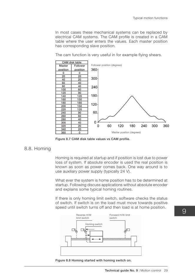
Technical guide No. 9 | Motion control 29
9
In most cases these mechanical systems can be replaced by electrical CAM systems. The CAM profile is created in a CAM table where the user enters the values. Each master position has corresponding slave position.
The cam function is very useful in for example flying shears.
Figure 8.7 CAM disk table values vs CAM profile.
8.8. Homing
Homing is required at startup and if position is lost due to power loss of system. If absolute encoder is used the real position is known as soon as power comes back. One way around is to use auxiliary power supply (typically 24 V).
What ever the system is home position has to be determined at startup. Following discuss applications without absolute encoder and explains some typical homing routines.
If there is only homing limit switch, software checks the status of switch. If switch is on the load must move towards positive speed until switch turns off and then load is at home position.
CAM disk tableMaster position
Follower position
0 020 2040 2060 4080 40100 60120 90140 120160 150180 180200 150220 120240 90260 60280 40300 40320 20340 20360 0
Follower position (degrees)
Master position (degrees)
Homing switch
Forward H/W limit switch
Reverse H/W limit switch
Figure 8.8 Homing started with homing switch on.
Typical motion functions
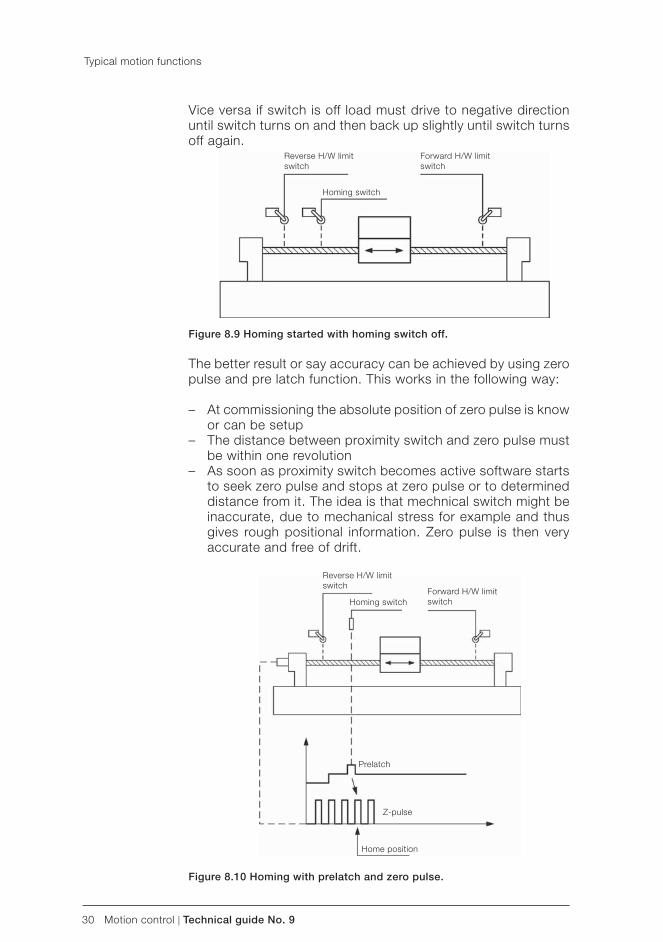
30 Motion control | Technical guide No. 9
Vice versa if switch is off load must drive to negative direction until switch turns on and then back up slightly until switch turns off again.
Figure 8.9 Homing started with homing switch off.
The better result or say accuracy can be achieved by using zero pulse and pre latch function. This works in the following way:
– At commissioning the absolute position of zero pulse is know or can be setup
– The distance between proximity switch and zero pulse must be within one revolution
– As soon as proximity switch becomes active software starts to seek zero pulse and stops at zero pulse or to determined distance from it. The idea is that mechnical switch might be inaccurate, due to mechanical stress for example and thus gives rough positional information. Zero pulse is then very accurate and free of drift.
Homing switch
Forward H/W limit switch
Reverse H/W limit switch
Homing switchForward H/W limit switch
Reverse H/W limit switch
Prelatch
Z-pulse
Home position
Figure 8.10 Homing with prelatch and zero pulse.
Typical motion functions
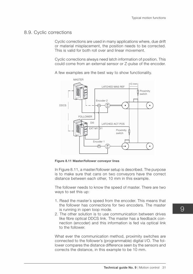
Technical guide No. 9 | Motion control 31
9
8.9. Cyclic corrections
Cyclic corrections are used in many applications where, due drift or material misplacement, the position needs to be corrected. This is valid for both roll over and linear movement.
Cyclic corrections always need latch information of position. This could come from an external sensor or Z-pulse of the encoder.
A few examples are the best way to show functionality.
Figure 8.11 Master/follower conveyor lines
In Figure 8.11, a master/follower setup is described. The purpose is to make sure that cans on two conveyors have the correct distance between each other, 10 mm in this example.
The follower needs to know the speed of master. There are two ways to set this up:
1. Read the master´s speed from the encoder. This means that the follower has connections for two encoders. The master is running in open loop mode.
2. The other solution is to use communication between drives like fibre optical DDCS link. The master has a feedback con-nection (encoder) and this information is fed via optical link to the follower.
What ever the communication method, proximity switches are connected to the follower’s (programmable) digital I/O. The fol-lower compares the distance difference seen by the sensors and corrects the distance, in this example to be 10 mm.
MASTER
DDCS
FOLLOWER
LATCHED ACT POS
LATCHED MAS REF
EXT M1 Di1
Di5
Encoder 2
Encoder 1
Proximity switch
Proximity switch
10 mm
Typical motion functions
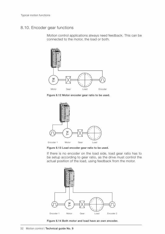
32 Motion control | Technical guide No. 9
8.10. Encoder gear functions
Motion control applications always need feedback. This can be connected to the motor, the load or both.
Motor Gear Load Encoder
Motor Gear LoadEncoder 1
Motor Gear LoadEncoder 1 Encoder 2
If there is no encoder on the load side, load gear ratio has to be setup according to gear ratio, as the drive must control the actual position of the load, using feedback from the motor.
Figure 8.12 Motor encoder gear ratio to be used.
Figure 8.13 Load encoder gear ratio to be used.
Figure 8.14 Both motor and load have an own encoder.
Typical motion functions
Technical guide No. 9 | Motion control 33
9
8.11. Virtual master/axis
Virtual master means that the reference values are applied to a model of a rotational axis that runs in the software. The virtual axis gives its speed reference to all its followers. The virtual axis gives full noise-free speed and positional signal in applications where two or more drives are synchronized.
Virtual axis is also very useful during system commissioning, as parts of machines can be tested without running the whole process.
Typical motion functions
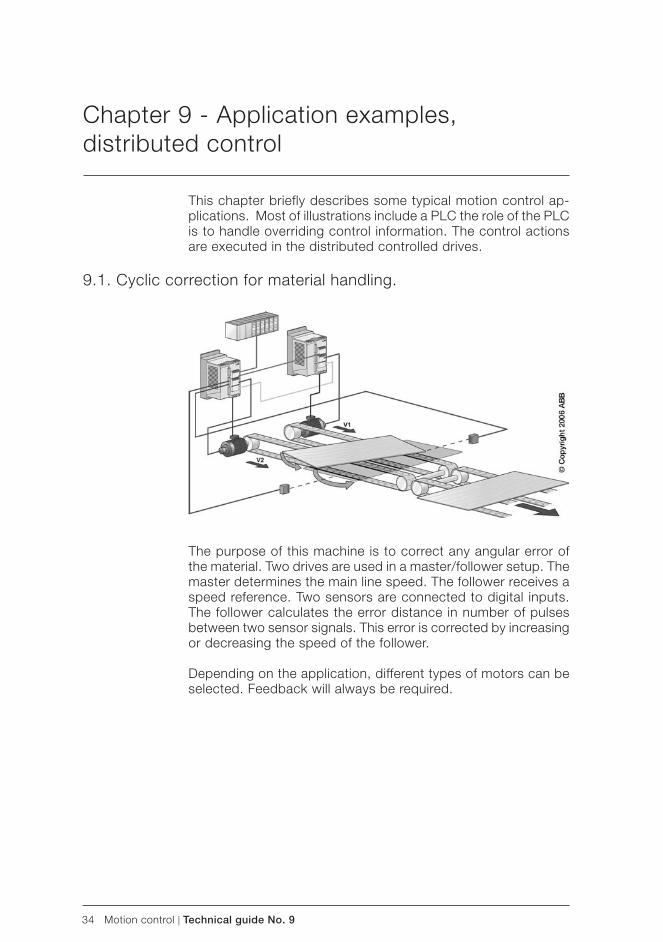
34 Motion control | Technical guide No. 9
The purpose of this machine is to correct any angular error of the material. Two drives are used in a master/follower setup. The master determines the main line speed. The follower receives a speed reference. Two sensors are connected to digital inputs. The follower calculates the error distance in number of pulses between two sensor signals. This error is corrected by increasing or decreasing the speed of the follower.
Depending on the application, different types of motors can be selected. Feedback will always be required.
Chapter 9 - Application examples, distributed control
This chapter briefly describes some typical motion control ap-plications. Most of illustrations include a PLC the role of the PLC is to handle overriding control information. The control actions are executed in the distributed controlled drives.
9.1. Cyclic correction for material handling.
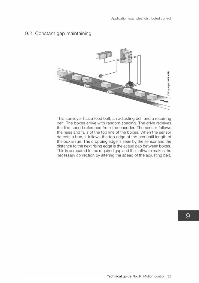
Technical guide No. 9 | Motion control 35
9
9.2. Constant gap maintaining
This conveyor has a feed belt, an adjusting belt and a receiving belt. The boxes arrive with random spacing. The drive receives the line speed reference from the encoder. The sensor follows the rises and falls of the top line of the boxes. When the sensor detects a box, it follows the top edge of the box until length of the box is run. The dropping edge is seen by the sensor and the distance to the next rising edge is the actual gap between boxes. This is compared to the required gap and the software makes the necessary correction by altering the speed of the adjusting belt.
Application examples, distributed control
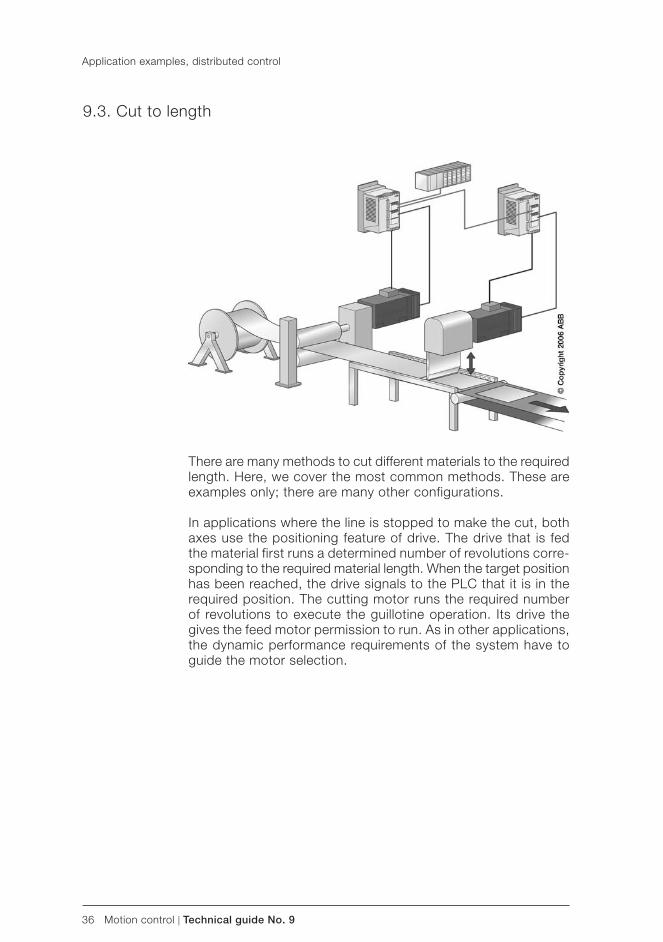
36 Motion control | Technical guide No. 9
Application examples, distributed control
9.3. Cut to length
There are many methods to cut different materials to the required length. Here, we cover the most common methods. These are examples only; there are many other configurations.
In applications where the line is stopped to make the cut, both axes use the positioning feature of drive. The drive that is fed the material first runs a determined number of revolutions corre-sponding to the required material length. When the target position has been reached, the drive signals to the PLC that it is in the required position. The cutting motor runs the required number of revolutions to execute the guillotine operation. Its drive the gives the feed motor permission to run. As in other applications, the dynamic performance requirements of the system have to guide the motor selection.
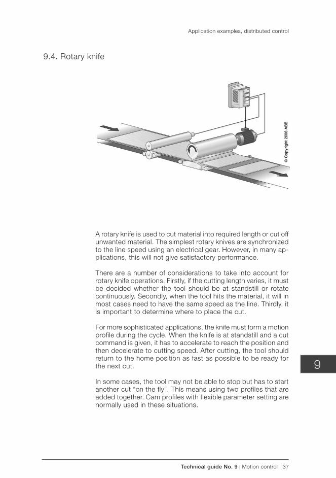
Technical guide No. 9 | Motion control 37
9
9.4. Rotary knife
A rotary knife is used to cut material into required length or cut off unwanted material. The simplest rotary knives are synchronized to the line speed using an electrical gear. However, in many ap-plications, this will not give satisfactory performance.
There are a number of considerations to take into account for rotary knife operations. Firstly, if the cutting length varies, it must be decided whether the tool should be at standstill or rotate continuously. Secondly, when the tool hits the material, it will in most cases need to have the same speed as the line. Thirdly, it is important to determine where to place the cut.
For more sophisticated applications, the knife must form a motion profile during the cycle. When the knife is at standstill and a cut command is given, it has to accelerate to reach the position and then decelerate to cutting speed. After cutting, the tool should return to the home position as fast as possible to be ready for the next cut.
In some cases, the tool may not be able to stop but has to start another cut “on the fly”. This means using two profiles that are added together. Cam profiles with flexible parameter setting are normally used in these situations.
Application examples, distributed control
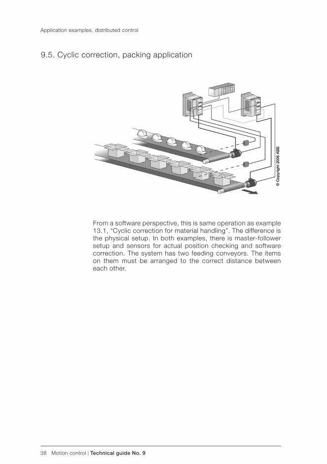
38 Motion control | Technical guide No. 9
9.5. Cyclic correction, packing application
From a software perspective, this is same operation as example 13.1, “Cyclic correction for material handling”. The difference is the physical setup. In both examples, there is master-follower setup and sensors for actual position checking and software correction. The system has two feeding conveyors. The items on them must be arranged to the correct distance between each other.
Application examples, distributed control
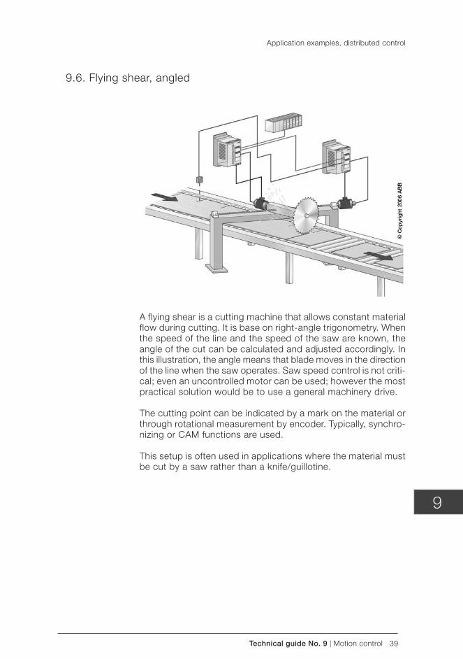
Technical guide No. 9 | Motion control 39
9
Application examples, distributed control
9.6. Flying shear, angled
A flying shear is a cutting machine that allows constant material flow during cutting. It is base on right-angle trigonometry. When the speed of the line and the speed of the saw are known, the angle of the cut can be calculated and adjusted accordingly. In this illustration, the angle means that blade moves in the direction of the line when the saw operates. Saw speed control is not criti-cal; even an uncontrolled motor can be used; however the most practical solution would be to use a general machinery drive.
The cutting point can be indicated by a mark on the material or through rotational measurement by encoder. Typically, synchro-nizing or CAM functions are used.
This setup is often used in applications where the material must be cut by a saw rather than a knife/guillotine.
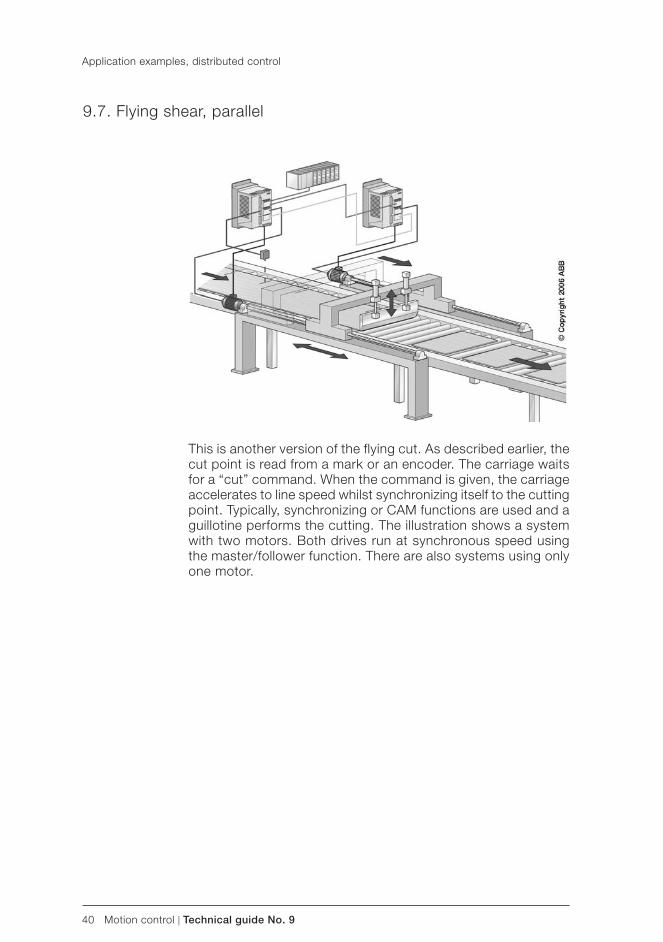
40 Motion control | Technical guide No. 9
Application examples, distributed control
9.7. Flying shear, parallel
This is another version of the flying cut. As described earlier, the cut point is read from a mark or an encoder. The carriage waits for a “cut” command. When the command is given, the carriage accelerates to line speed whilst synchronizing itself to the cutting point. Typically, synchronizing or CAM functions are used and a guillotine performs the cutting. The illustration shows a system with two motors. Both drives run at synchronous speed using the master/follower function. There are also systems using only one motor.
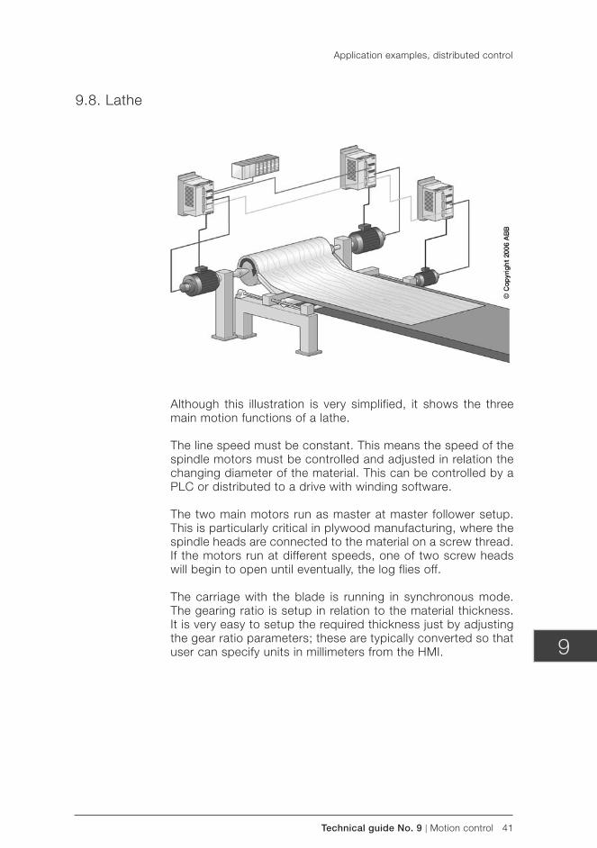
Technical guide No. 9 | Motion control 41
9
Application examples, distributed control
9.8. Lathe
Although this illustration is very simplified, it shows the three main motion functions of a lathe.
The line speed must be constant. This means the speed of the spindle motors must be controlled and adjusted in relation the changing diameter of the material. This can be controlled by a PLC or distributed to a drive with winding software.
The two main motors run as master at master follower setup. This is particularly critical in plywood manufacturing, where the spindle heads are connected to the material on a screw thread. If the motors run at different speeds, one of two screw heads will begin to open until eventually, the log flies off.
The carriage with the blade is running in synchronous mode. The gearing ratio is setup in relation to the material thickness. It is very easy to setup the required thickness just by adjusting the gear ratio parameters; these are typically converted so that user can specify units in millimeters from the HMI.
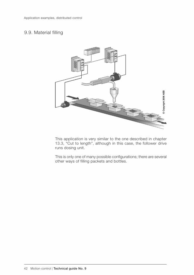
42 Motion control | Technical guide No. 9
Application examples, distributed control
9.9. Material filling
This application is very similar to the one described in chapter 13.3, “Cut to length”, although in this case, the follower drive runs dosing unit.
This is only one of many possible configurations; there are several other ways of filling packets and bottles.
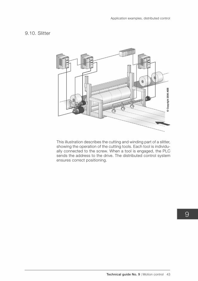
Technical guide No. 9 | Motion control 43
9
Application examples, distributed control
9.10. Slitter
This illustration describes the cutting and winding part of a slitter, showing the operation of the cutting tools. Each tool is individu-ally connected to the screw. When a tool is engaged, the PLC sends the address to the drive. The distributed control system ensures correct positioning.
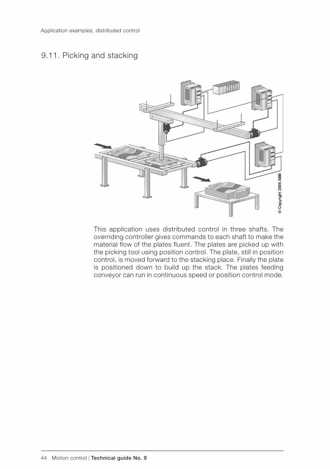
44 Motion control | Technical guide No. 9
Application examples, distributed control
9.11. Picking and stacking
This application uses distributed control in three shafts. The overriding controller gives commands to each shaft to make the material flow of the plates fluent. The plates are picked up with the picking tool using position control. The plate, still in position control, is moved forward to the stacking place. Finally the plate is positioned down to build up the stack. The plates feeding conveyor can run in continuous speed or position control mode.
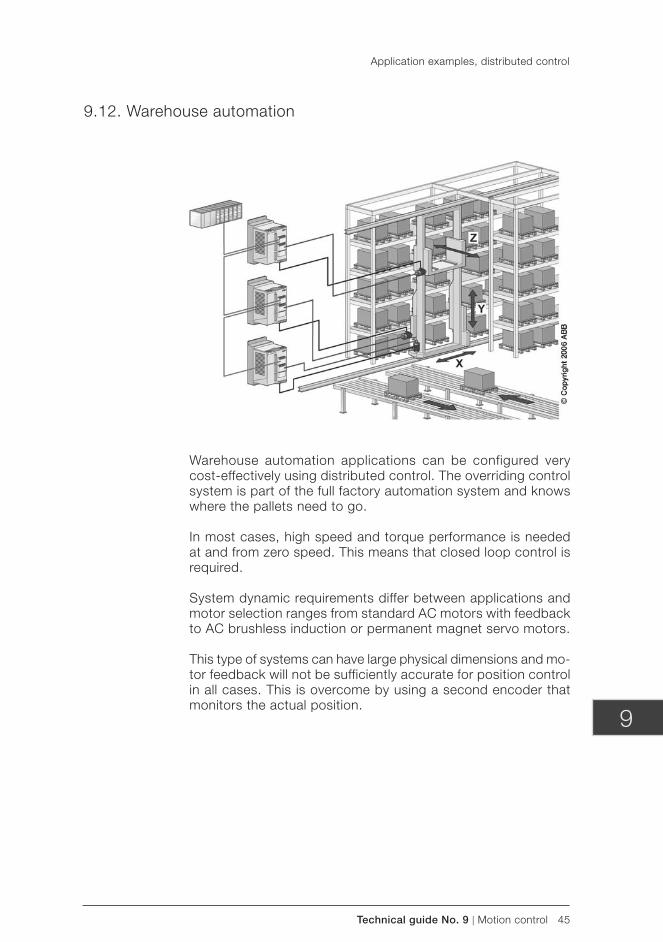
Technical guide No. 9 | Motion control 45
9
Application examples, distributed control
9.12. Warehouse automation
Warehouse automation applications can be configured very cost-effectively using distributed control. The overriding control system is part of the full factory automation system and knows where the pallets need to go.
In most cases, high speed and torque performance is needed at and from zero speed. This means that closed loop control is required.
System dynamic requirements differ between applications and motor selection ranges from standard AC motors with feedback to AC brushless induction or permanent magnet servo motors.
This type of systems can have large physical dimensions and mo-tor feedback will not be sufficiently accurate for position control in all cases. This is overcome by using a second encoder that monitors the actual position.
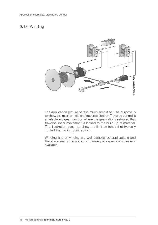
46 Motion control | Technical guide No. 9
Application examples, distributed control
9.13. Winding
The application picture here is much simplified. The purpose is to show the main principle of traverse control. Traverse control is an electronic gear function where the gear ratio is setup so that traverse linear movement is locked to the build-up of material. The illustration does not show the limit switches that typically control the turning point action.
Winding and unwinding are well-established applications and there are many dedicated software packages commercially available.

Technical guide No. 9 | Motion control 47
9
Application examples, distributed control
9.14. Wrapping
The i l lustrat ion shows a simple packaging appl icat ion. The electrical gear is formed between two motors.
48 Motion control | Technical guide No. 9
Chapter 10 - Motion control – *Glossary of terms
AccelerationThe rate of increase of velocity, usually expressed as meters per second per second, or meters per second2 (m/s2).
AccuracyThe measured value compared to the desired value. In motion control, this will most often refer to a position description, defined in terms a plus or minus deviation from the commanded value, or in terms of a range of values around the set point.
Active front endA front end processor which receives data from both upstream and downstream equipment and makes changes without refer-ence to external controls.
Actual positionThe position of an axis compared to the desired position. This can be either the final position at the end of the move or the lag between the commanded position and the measured position at any point during the move. The latter is commonly known as following error.
AC servoA motor drive that generates sinusoidal shaped motor currents.
AlarmA warning that a parameter has moved out of acceptable or defined limits or an indication that a component has failed or is malfunctioning. It can either warn or advise an operator or be in the form of an output signal that can initiate corrective action or switch a process off.
Analog servoMost commonly found in hydraulic and similar systems, an analog servo uses analog control and feedback systems such as voltage variation and changes in pressure.
Analog signalA signal that varies in step with the parameter being measured. Typical examples include a 0-10 volt motor control signal and a pneumatic control pressure.
Technical guide No. 9 | Motion control 49
9
Axes of motionThe major directions along which controlled movement of a machine part or component occurs. These axes are usually defined as follows:X: Linear motion in positioning directionY: Linear motion perpendicular to positioning directionZ: Vertical linear motionA: Angular motion around X (roll)B: Angular motion around Y (pitch)C: Angular motion around Z (yaw)
AxisThe main directions along which a tool, component or workpiece will move.
Brushless servoA servo drive which uses electronic commutation of the cur-rent rather than achieving it through mechanical brushes and a commutator.
BusA series of conductors acting as path to send information be-tween control elements and components.
Centralized controlA system with the software located in one physical unit. All input information from sensors and feedback devices are connected to this unit and control commands are sent from it.
Circular interpolationA process of moving a component in a circle by moving along two axes in a series of straight lines generated by software.
Close motion loopThe reference signal is compared to the feedback signal and the discrepancy is corrected in an amplifier circuit.
Collision detectionDescribes the process of using sensors to detect a possible col-lision between parts or components. The sensors can produce alarms to stop the movement or slow it to produce a low speed mating of the components.
CommutationEnsuring that the correct motors phase receive the correct cur-rents or voltages. It can be done electromechanically via the brushes and commutator as in brush type motors, or electroni-cally as used in brushless motors.
Motion control – Glossary of terms
50 Motion control | Technical guide No. 9
Motion control – Glossary of terms
ConverterChanging AC to DC or DC to AC, most often with a diode rectifier or thyristor rectifier circuit. The term “converter” may also refer to the process in an adjustable frequency drive. This consists of a rectifier, a DC intermediate circuit, an inverter and a control unit.
Co-ordinationIntegration two or more axes of motion to produce an otherwise impossible motion. Sensors and other internal or external com-mands may also be used to assist the movements.
Current controllerAn electronic function which gives the proper instant current needed by the load. The current is controllable to limit the maximum current and reduce the danger of overloads damag-ing the motor.
Cut to lengthAn algorithm that feeds material a set distance so that a pro-cess can be performed on a correctly sized length. Feedback systems are usually used to ensure that the selected length is repeated accurately.
DC busA common communications circuit that uses a DC voltage as reference. The term may also refer to a power distribution system shared by several components.
DecelerationThe rate of decrease of velocity. Usually measured in units of velocity change for each unit of time, ie, meters/sec/sec or, meters/sec2.
Decentralized controlA control method made up of separated control elements dis-tributed over an area or process. The individual elements are essentially independent of each other, although they will have some means of communicating.
Deterministic scan timeThe frequency at which a Programmable Logic Controller ( PLC) executes a Program. Normally measured in milliseconds this will include the time required to read a specific set of instructions and return to the initial instruction.
Device level networkA common network cable that eliminates individual links between the PLC and each device.
Technical guide No. 9 | Motion control 51
9
Diagnostic codeA code displayed on an operator interface or in a program, used to indicate a fault condition as well as usually its position.
Digital motion controlA motion control system that uses binary code for calculating.
Digital servoA servo motor that uses binary code for all calculations and feed back.
Digital signalA signal in the form of binary pulses if information, based on voltage levels that represent the values 0 and 1.
DriveAn electronic device that controls the electric current supplied to a motor.
EfficiencyThe efficiency of a motor compares the mechanical output to the electrical input and is a measure of how well the motor turns the electrical energy it receives into a useful mechanical output.
Electronic cam profilesA technique that replaces mechanical cams with electronics to perform non-linear motion.
Electronic clutchA method of using electronic cams or gearing functions to pro-duce a slave profile based on a master position.
Electronic gearingSimulating mechanical gears by electrically synchronizing one closed loop axis to a second.
Electronic line shaftA virtual axis which synchronizes other axes either through using electronic gearing or camming profiles.
EncoderA feedback device that translates mechanical motion into elec-trical signals that indicate position. Incremental and absolute encoders are used to indicate incremental or absolute changes of position respectively.
Motion control – Glossary of terms
52 Motion control | Technical guide No. 9
Encoder resolutionThe number of electrically identified positions in a 360 degree rotation of a shaft.
EnDatA standard interface for serial data transfer, particularly for posi-tion and parameters.
EMC/CEEuropean Directive that sets standards and limits for conducted and radiated emissions. Drives may need line filters or other components to conform to the directive.
Emergency stopAn emergency stop function must meet all of the following re-quirements: – It must override all other functions and operations under all
conditions – Power to machine actuators that can cause hazard must
be interrupted as quickly as possible without creating other hazard
– Reset must not initiate a restart – The emergency stop shall be either a Category 0 or a Category
1 stop. The choice of emergency stop must be decided in accordance with the requirements of the application
EthernetA very widely used open networking standard. Normally used for office automation and operating at a communications speed of 1.5 megabits/sec, newer versions are capable of up 100 megabits/sec.
EventWhen an input parameter changes state, such as at the trigger-ing of a limit switch or proximity sensor.
FaultA condition a drive or control is in having attempted an illegal process and becoming disabled.
FeedbackWhen a controlled machine sends a signal to inform that it has responded to a control signal.
Feedback deviceGive information of the actuators’ real speed and position to the motion controller.
Motion control – Glossary of terms
Technical guide No. 9 | Motion control 53
9
Feed forwardA method that compensates for known errors in a control loop. It depends only on the command, not the measured error.
Fiber opticA glass or plastic fiber guide that transmits light that is trans-lated into current or used to determine the open/close state of a current path.
FieldBusA local area network, as defined by ISA standard S50.02 and which is used to connect control elements and sensors to each other.
Flying restartWhen a motor is restarted while spinning, normally done by sampling the motor speed, encoder input, or back EMF.
Flying virtual masterThe ability of a motion controller to switch from one virtual en-coder to another instantaneously. This feature makes it possible to use advanced synchronizing features.
Following errorThe difference between the commanded position of an axis and its actual position, a difference that varies with the speed of the axis.
Frameless motorA motor consisting of only the stator and rotor. This allows a manufacturer to incorporate it into a machine directly, cutting the need for any shafts or other mechanical transmissions.
GantryAn overhead framework that can move in the X, Y, and/or Z axes, carrying a variety of tools or devices to perform tasks.
G codeSoftware used for programming machining processes, such as 3-axis milling and 2-axis wire cutting.
Hard, real-time controlThe ability of a controller to respond to an event immediately. PLCs are designed for this, though PCs pose more of a problem.
Hardware limit switchA switch that alters the electric circuit associated with the machine or equipment and which is operated by some part or motion of a power-driven machine or equipment.
Motion control – Glossary of terms
54 Motion control | Technical guide No. 9
Holding brakeA friction device which sets a brake when power is removed.
Home positionA position which acts as a reference for all absolute positioning movements. It is normally set at power-up and remains valid as long as the control system is operational.
HomingThe act of calibrating axes by finding a unique reference position, usually at power up.
Human-machine interface (HMI)A console which displays data and receives commands, allowing the operator to control the drive.
IGBT insulated-gate bipolar transistorThe IGBT is usually used in switching power supplies and in mo-tor control applications and forms the basis of the most modern and capable variable speed drives.
InchingAdvancing a motor in small steps through repeated closure of a switch.
IndexerAn electronic device that allows a PLC to control the movements of a stepping motor.
IndexingAn axis or axes moving to a pre-programmed position.
InertiaA property of matter in which a body continues in a state of rest or uniform motion unless acted on by an external force.
In position windowA range of acceptable positions around the commanded posi-tion point.
InterpolationWhen two or more axes move in a co-ordinated way to produce a linear or circular motion.
InverterA device that converts DC power to AC power. Typically used as a part of the frequency converter.
Motion control – Glossary of terms
Technical guide No. 9 | Motion control 55
9
Jerk limitationA feature that limits the rate of change of acceleration with the aim of eliminating mechanical jerking during speed changes.
Jitter free synchronizationThe process of matching the acceleration and deceleration of a driven slave drive to the master drive to provide a smooth transition.
JogAn axis moving at a fixed velocity and acceleration/deceleration rate, in a chosen direction, but with no specific destination.
KPVelocity Loop Proportional Gain. Determines how much velocity error the servo system will allow during a move. See also: Tuning
KVPosition Loop Gain. Determines how much positioning error, or following error, will be allowed by the servo system during a move. See also: Tuning
Length unitsThe linear units for programming and configuring an axis, often defined in inches, feet, meters, or millimeters.
LinearWhere the output varies in direct proportion to the input.
Loop update timesThe time required to calculate the process variable from the following error.
Motion control Any tool or actuator controlled by motion software. The system can be hydraulic, pneumatic, electronic or any combination of these. Whatever the system, the profile for movement is written into the software code and the actuator has to follow this as ac-curately as possible. The actual movement and the reference are always compared by feedback devices and the motion controller aims to minimize the discrepancy.
Modulo ValueThe position increment at which a rotary axis position returns to 0, ie, 360 degrees.
Motion control – Glossary of terms
56 Motion control | Technical guide No. 9
NoiseAn unwanted electrical signal, usually the result of radio frequency or electromagnet ie, interference from devices such as AC power lines, motors, generators, transformers and radio transmitters.
OffsetDistance between the actual zero reference point and a pro-grammed zero reference point.
Open architectureHardware and/or software with standard features that numerous vendors can incorporate into their own products, which can then connect to each other and work together easily.
Open loop/close loopOpen loop control is where a control system has no external references with which to govern its speed or position. A closed loop control system is one which uses signals fed back from external sensors in order to correct the position or velocity and make it conform to the commanded value.
OvercurrentA current above the rated current of the drive, applied to maintain a set position or move to a new position.
OverrideThe act of forcing an axis to move during a fault condition. It is often used to force an axis to move away from an overtravel limit switch.
OvershootWhere the output of a system goes beyond the desired value.
Over temperatureA warning or alarm that indicates that a motor or drive is too hot, most often the result of too high current demand.
PCPersonal Computer
PhasingAdjusting the position of one axis with respect to others, to correct for small registration problems, usually done while the axes are moving.
PLCProgrammable Logic Controller. A computer that uses fast, re-peatable deterministic scan times to control equipment.
Motion control – Glossary of terms
Technical guide No. 9 | Motion control 57
9
PLSProgrammable Limit Switch. A device that converts the rotary motion of a shaft into digital signals. It is typically used to improve positioning accuracy.
Point-to-point wiringWiring each drive directly to the PLC. The method cuts out the communication delays introduced by a network.
Position errorError caused when the difference between the actual position and the command position is greater than a set amount.
PositioningWhen a move is specified by target position, velocity and ac-celeration. The target position can be an absolute position, or one relative to the current position.
Position loopSignals that generate position information based on position feedback.
Printmark synchronizationA method of controlling speed by comparing the position of a mark on a product with its expected position and then compen-sating for the difference.
ProfileA graphical representation of movement, with axes of position vs. time, velocity vs. time or torque vs. time.
Programmable Limit SwitchSee PLS
Programming languageA stylized communication method for controlling the behavior of a machine.
ProtocolA specified method of encoding information for transmission.
Pulse width frequencyThe switching rate of an IGBT.
Pulse-width modulationA switch-mode control method based on varying on/off times of the voltage pulses applied to the transistors.
Motion control – Glossary of terms
58 Motion control | Technical guide No. 9
QuadratureA technique used to detect direction of motion based on sepa-rating signal channels by 90’ (electrical).
Ramp function generatorDevice or mathematical model that produces a square, triangular or sinusoidal wave output.
Rated speedThe maximum speed at which a motor can rotate.
Real masterFeedback that provides position information for a synchronized axis.
RectifierA device that converts AC power into DC for use by converter drives.
ReferencingThe setting of a feedback device relative to the real world.
RegenA motor /drive system can produce regenerative power during deceleration, power that can be fed to other machines on the network.
ResolverA type of position transducer that uses magnetic coupling to measure absolute shaft position.
RollfeedA function that keeps the linear speed of the feed material con-stant as the diameter of the rotary axis changes.
RotaryMoving in a circular way, with measurement of position based on degrees.
Safe offA method of ensuring that power will not travel from the drive to the motor.
SCADA-Supervisory Control & Data Acquisition.A system of software and hardware that controls a production process and collects data on its efficiency.
Motion control – Glossary of terms
Technical guide No. 9 | Motion control 59
9
S curveA way of accelerating and decelerating a motor slowly to reduce mechanical shock. Although more sophisticated than linear ac-celeration, it does not have the performance of camming.
Sequence of operationA series of steps that causes a machine to perform an action.
SERCOSSerial Real-time Communications Standard. An open communi-cations protocol for motion-control networks, with transmission speeds over a fiber-optic cable of up to 4 megabits/sec.
Serial communicationsThe transmission of digital 1s and 0s in a series over a single cable.
Servo mechanismAn automatic, closed-loop motion control system that uses feedback to control a desired output, for example position, velocity, or acceleration.
Servo motorA motor that can be precisely controlled. The drive that powers it gets accurate feedback on the motor’s position from a resolver or encoder.
Shielded cableA cable that has a metallic sleeve encasing the conductors at its centre The metal sleeve is grounded to prevent electrical noise affecting the signals on the cable.
SinCosAn encoder used in servo control. It outputs both digital and high resolution analog signals.
Software limit switchA switch based on software rather than a physical object. It is used to turn physical outputs on and off, depending on the level of a particular input, from devices such as servo motors, resolvers or encoders.
SSIAcronym for Serial Synchronous Interface. A type of multi-turn absolute encoder that sends position information as a serial string in Gray code format.
Motion control – Glossary of terms
60 Motion control | Technical guide No. 9
SynchronizationWhen several functions of a machine follow a common control signal.
TachometerAn electromagnetic feedback transducer that provides an analog voltage signal proportional to the rotational speed of a motor.
TaskA software system control that determines the execution rates and priority levels for software modules running in a drive or PLC.
TCP/IPTransmission Control Protocol/Internet Protocol. A method of encoding data into a series of “packets” for transmission over a network, initially designed for the Internet but now often used in production control.
Teach positionThe position of an axis that is “taught” into the motion control program. Once the axis is moved to the desired position, the “teach position” is entered into the motion program automati-cally by the control.
TelegramA data packet used to communicate between controller and device.
TeleServiceA feature that allows a controller or PLC to be serviced.
TNVelocity Loop Integral Action Time. Associated with KP. When the measured velocity moves beyond the tolerance value set in KP, TN determines how quickly the drive will bring the velocity back within the specified tolerance. See also: Tuning
Torque limitationA servo function that allows the current supplied to a servo motor to be monitored and limited.
TuningAdjusting the servo drive’s internal characteristics to give it the ability to control the reflected inertia and give the axis a smooth position/ velocity profile.
Motion control – Glossary of terms
Technical guide No. 9 | Motion control 61
9
Twisted pairTwo wires twisted together with the aim of eliminating electrical noise.
VxWorksTM
VxWorksTM is a real-time operating systems that guarantees an absolutely deterministic response. Its benefits include real-time behavior, stability, operating time and an efficient memory ef-ficiency.
VelocityThe speed at which a motor or mechanical system runs.
Velocity loopA servo control function that adds a velocity command signal to a speed feedback signal. The resultant signal is output as a torque command signal.
Virtual masterAn encoder signal created in software of a motion control to allow several servo systems to be synchronized.
WarningAn error condition received from a drive or a controller, indicating that a fault will occur if the problem is not rectified.
WintelMicrosoft’s WindowsTM operating system running on Intel’s mi-croprocessors, an industry standard for PCs.
Zero point of feedbackThe point at which the encoder position and the physical position of a servo motor line up.
* Glossary of terms resource list:OMAC Motion for Packaging Working Group, Education Subcommittee, Glossary of Motion Control Terms, August 2001.
Motion control – Glossary of terms
62 Motion control | Technical guide No. 9
Chapter 11 - Index
A absolute positioning 54acceleration 12, 25, 55, 57, 59AC drive technology 7algorithm 12, 14, 17, 50analogue 11asynchronous 12, 14, 15asynchronous servo motor 15
Bback EMF 12, 19, 20, 53brushes 11, 16, 49brushless 11, 49brushless DC 11, 12
CCAM functions 39, 40centralized control 8centralized system 8centrally 8coils 21commutator 11, 16, 49composite flux vector 16computing power 12control system 10, 43, 45, 51, 54, 56, 59control unit 8, 50cyclic correction 10
DDC-link capacitance 11decentralized control 9decentralized system 8distance 10, 25, 27, 30, 31, 34, 35, 38, 50DTC control 12dynamic 7, 13, 28, 36, 45
Eefficiency 15, 51, 58, 61electronic 46, 49, 51, 54, 55encoders 15, 17, 22, 31, 51, 59
Ffans 15, 20feedback 7, 9, 10, 11, 12, 13, 15, 16, 17, 18, 21, 24, 31, 32, 45, 48, 49, 51, 55, 57, 58, 59, 60, 61fieldbus 7flux 16flying shear 39
Hhardware 9, 58heat 15high performance drives 7, 9, 12high power DC drives 11
Iinduction 12, 14, 15, 45
Jjerk 25
Llathe 41linear and roll-over positioning 26
Mmagnetizing circuit 11magnetizing current 14material handling 34, 38motion control 1, 3, 7, 9, 10, 11, 15, 22, 24, 34, 48, 51, 59, 60, 61motion control application 7motion controller 7, 9, 11, 21, 52, 53, 55motion loop 49
Ooverload 15, 19
Ppacking application 38performance 7, 8, 9, 12, 13, 14, 15, 17, 21, 36, 37, 45, 59permanent magnets 11, 16phase 13, 15, 16, 17, 21, 49phase delay 15phasing error 17PLC 9, 10, 34, 36, 41, 43, 50, 54, 56, 57, 60poles 14position 7, 10, 11, 12, 13, 16, 17, 21, 24, 25, 26, 27, 28, 29, 30, 31, 32, 36, 37, 38, 45, 48, 51, 52, 53, 54, 55, 56, 57, 58, 59, 60, 61position control 21, 45positioning 7, 26, 28, 36, 43, 49, 54, 55, 57position interpolator 25profile generator 7, 24pulse encoder 11
Rreference profile 7reference value 7, 8, 18resolver 12, 21, 59rotary knife 37rotor 12, 13, 15, 16, 17, 20, 21, 53rotor current 15rotor position 12, 17

Technical guide No. 9 | Motion control 63
9
Ssample time 7second encoder 21, 45sensor 12, 22, 31, 34, 35, 52servo 11, 12, 13, 14, 15, 16, 17, 18, 19, 20, 45, 48, 49, 51, 55, 59, 60, 61sinusoidal 11, 12, 14, 16, 48, 58slip 12slitter 43speed controller 11, 12, 17, 18, 21, 24synchronous servo motor 13, 15, 16, 19synchronous servo motors 15
Ttemperature rise 15
Vvector 12, 16velocity 25, 48, 50, 55, 56, 57, 59, 60, 61
Wwinding 14, 21, 41, 43
Zzero pulse 30
Index


3AFE
6869
5201
RE
V B
EN
11.
2.20
13 #
1668
0
Contact us
For more information please contact your local ABB representative or visit:
www.abb.com/driveswww.abb.com/drivespartners
© Copyright 2013 ABB. All rights reserved. Specifications subject to change without notice.

Technical guide No.10Functional safety
ABB drives


10
Technical guide No. 10 | Functional safety 1
© Copyright 2011 ABB. All rights reserved.
Specifications subject to change without notice.
3AUA0000048753 REV D EN 30.3.2011 #15511
Technical guide No. 10Functional safety

2 Functional safety | Technical guide No. 10
10
Technical guide No. 10 | Functional safety 3
About this document .................................................................................7
Part 1 – Theory and background ...............................................................8
Safety and functional safety ................................................................9Machinery Directive ............................................................................9Changes in the new Machinery Directive ............................................11Hierarchy of the European harmonized standards system ...................12
Part 2 – New approach ............................................................................14
Two standards – IEC and ISO ............................................................15Standards for risk minimization .........................................................16Standards for electronic safety systems .............................................16Product-specific safety standards (type-C standards) .........................18Specific standard for safety-related drive systems ..............................18Standardized safety functions ...........................................................19
Part 3 – Steps to meet Machinery Directive requirements .......................22
STEP 1: Management of functional safety ..........................................23STEP 2: Risk assessment .................................................................24STEP 3: Risk reduction .....................................................................26STEP 4: Establishing safety requirements ..........................................28STEP 5: Implementing functional safety system .................................32STEP 6: Verifying a functional safety system ......................................33STEP 7: Validating functional safety system .......................................37STEP 8: Documenting functional safety system ..................................37STEP 9: Proving compliance .............................................................38
Glossary ...................................................................................................40
Index .......................................................................................................42
Contents
4 Functional safety | Technical guide No. 10
Disclaimer
This document is an informative guide intended to assist the us-ers, specifiers and manufacturers of machinery and the related people in achieving a better understanding of the requirements of the EU Machinery Directive, and the measures required to achieve conformity with the directive and the harmonized stand-ards under it.
This document is not intended to be used verbatim, but rather as an informative aid.
The information and examples in this guide are for general use only and do not offer all of the necessary details for implementing a safety system.
ABB Oy Drives does not accept any liability for direct or indirect injury or damage caused by the use of information found in this document. The manufacturer of the machinery is always responsible for the safety of the product and its suitability under the applicable laws. ABB hereby disclaims all liabilities that may result from this document.
10
Technical guide No. 10 | Functional safety 5
About this document
This document introduces the Machinery Directive and the standards that must be taken into account when designing a machine, in order to ensure operational safely.
The aim of the document is to explain, in general terms, how the process for meeting the requirements of the Machinery Directive is carried out and CE marking is obtained. CE marking indicates that the machinery conforms to the requirements of the Directive.
Note:This document gives only an overview of the process for meeting the essential requirements of the Machinery Directive. The manufacturer of the machinery always remains ultimately responsible for the safety and compliance of the product.
The document is divided into three parts:
– Part 1 – Theory and Background – introduces the idea be-hind functional safety and how to comply with the Machinery Directive. It also presents the upcoming changes in the new Machinery Directive and explains the hierarchy of the Euro-pean harmonized standards system.
– Part 2 – New Approach – presents the new Machinery Direc-tive related standards that are replacing old standards. It also introduces the two standard systems and lists a number of safety relevant standards and safety functions.
– Part 3 – Steps to Meet Machinery Directive Requirements – introduces nine steps that help in the process of fulfilling the essential requirements of the Machinery Directive.
6 Functional safety | Technical guide No. 10
Part 1 – Theory and background
The national laws of the European Union require that machines meet the Essential Health and Safety Requirements ( EHSR) defined in the Machinery Directive and in the harmonized standards under the Directive. This means that all new machinery must fulfill the same legal requirements when supplied throughout the EU. The same standards are also recognized in many areas outside Europe, for example through equivalency charts, which facilitates machinery trade and machine shipments between countries within and even outside the EU.
Why must machinery meet these requirements? Because conformity helps to prevent accidents and consequent injury. Furthermore, by complying with the Machinery Directive and the relevant harmonized standards, machine manufacturers can rest assured they have met their obligations to design and deliver safe machines that comply with national laws.
For manufacturers, new and improved safety strategies are becoming a way of improving their productivity and competitiveness in the market. The aim of conventional safety systems has been to achieve comprehensive operational safety and meet legal obligations. This has been done by using add-on electrical and mechanical components, even at the cost of productivity. Operators can, in certain circumstances, override these systems when attempting to improve productivity, which can lead to accidents.
With modern safety systems, the safety of the processes and the operator can be taken into account while maintaining productivity. One example of this is keeping the machine running but at a lower speed to maintain safe operation. With modern safety solutions, safety can be an integrated part of machine functionality, and safety solutions are not just afterthoughts, added in order to meet regulations.
Safety systems can be implemented effectively through defined processes, to achieve specific safety performance and use certified subsystems as building blocks for safety systems. Meeting safety standards is expected in the industry, and certified subsystems such as drives are becoming a must in the marketplace. Machine safety is one of the most rapidly growing areas of importance in industrial automation.
10
Technical guide No. 10 | Functional safety 7
Part 1 – Theory and background
Safety and functional safety
The purpose of safety is to protect people and the environment from accidents and, in this case, from machinery. Functional safety systems do this by lowering the probability of undesired events, so that mishaps are minimized when operating machinery. Safety standards define safety as freedom from unacceptable risk. What is acceptable is defined by society. Machine builders should always use the same (the most stringent) acceptability criteria for all market areas, regardless of regional differences.
The most effective way to eliminate risks is to design them away. But if risk reduction by design is not possible or practical, safe-guarding through static guards or functional safety is often the best option. When machines are stopped quickly and safely or operated at a reduced speed during specific times, in order to reduce risk, higher machine productivity, uptime and less abrupt safety system behavior can be achieved. At the same time, the legal obligations are met and the safety of people and the envi-ronment is ensured.
Functional safety in machinery usually means systems that safely monitor and, when necessary, take control of the machine applications to ensure safe operation. A safety-related system is a system that implements the required, necessary safety functions. Functional safety systems are designed to detect hazardous conditions and return operation to a safe state, or to ensure that the desired action, such as safe stopping, takes place.
Monitoring can include speed, stopping, direction of rotation, and standstill. When the safety system is executing an active safety function, for example monitoring a crawl speed, and the system behavior deviates from that which is expected (for ex-ample, the system runs too fast), the safety system detects the deviation and actively returns machine operation to a safe state. This can be done, for example, by stopping the machine safely and lowering the torque of the motor shaft.
A safety system is not part of standard machine operation, but any failure in the safety system will immediately increase the risks related to machine operation.
Machinery Directive
The Machinery Directive, with the harmonized standards listed thereunder, defines the Essential Health and Safety Requirements ( EHSR) for machinery at European Union level. The EHSR are listed in Annex I of the Machinery Directive.
8 Functional safety | Technical guide No. 10
The idea behind the Machinery Directive is to ensure that a machine is safe and that it is designed and constructed so that it can be used, configured and maintained throughout all phases of its life, causing minimal risk to people and the environment.
The EHSR state that when seeking solutions for designing and building safe machines, machine manufacturers must apply the following principles in the given order (also known as the 3-step method):
1. Eliminate or minimize the hazards as much as possible by considering safety aspects in the machine design and construction phases.
2. Apply the necessary protection measures against hazards that cannot be eliminated.
3. Inform users of the risks that remain despite all feasible protection measures being taken, while specifying any requirements for training or personal protective equipment.
Complying with the EHSR of the Machinery Directive allows the machine manufacturer to affix the CE marking on the machine. With CE marking the manufacturer guarantees that the product meets all regulations on the free movement of goods, as well as the essential requirements of the relevant European Directives, in this case the Machinery Directive.
Note: There might also be other directives that apply, eg, low voltage directive and EMC directive. Only Machinery Directive require-ments are covered in this guide.
Note: CE marking according to the Machinery Directive is affixed only on a complete machine, not to the components of which it consists. Thus, the manufacturer of the product, or the rep-resentative of the manufacturer, is responsible for CE marking, not the manufacturer of the component that is included in the final product.
The machine manufacturer is responsible for carrying out the related risk analysis, following through the steps presented in Part 3, and ensuring compliance with the requirements. The component manufacturer is responsible for realizing the safety performance (SIL / PL level) of the said component’s safety function, when the component is appropriately used. A component in this case could be a safety relay, or an AC drive with integrated safety functionality.
Part 1 – Theory and background
10
Technical guide No. 10 | Functional safety 9
Changes in the new Machinery Directive
A new Machinery Directive 2006/42/EC, replaced the old Directive 98/37/EC, from December 29, 2009 onward.
There are no dramatic changes between the old and the new, revised Directive. The aim of the new Directive is to reinforce the achievements of the old Machinery Directive on the free circulation and safety of machinery and to improve its application.
Highlights of the changes in the current Machinery Directive are compared to the previous directive as follows:
– Changes in how conformity is evaluated for dangerous machines listed in the Machinery Directive’s Annex IV.Along with the new directive, the manufacturer can carry out self-certification without a recognized test center. In order to do this, the manufacturer must have a quality assurance procedure that has been implemented according to the requirements presented in the Machinery Directive’s Annex X.
– Changes in the Essential Health and Safety Requirements that are presented in the Machinery Directive’s Annex I.The manufacturer must now carry out a risk assessment on the EHSR.
– Changes in proving the safety of different products.The same machine regulations will apply to machinery, exchangeable equipment, safety components etc. The products must include CE conformity assessment, declaration of conformity and the requisite user information.
– Changes in the requirements for part or incomplete machines.A part or an incomplete machine is a component or a series of components that cannot, by themselves, perform a specific function. Such a part is attached to other parts, incomplete machines or machines to form a machine according to the definition in the Machinery Directive.
In addition to the manufacturer declaration, the manufacturer must now also supply a declaration of incorporation that defines which requirements of the directive apply to the part or incomplete machine and have been complied with. Product documentation must also include installation instructions.
– Changes concerning the Low Voltage Directive.The scope of the Low Voltage Directive is now related to a product instead of a risk. There is also now a clearer differentiation between the Machinery Directive and the Low Voltage Directive.
Part 1 – Theory and background
10 Functional safety | Technical guide No. 10
– Changes in hazard analysis.The hazard analysis is replaced by mandatory risk assessment and risk evaluation.
– Changes in production control.Series machines have now internal production controls, speci-fied in the Machinery Directive’s Annex VIII.
– Changes in the validity of EC Type Examination certifications.A recognized test center must inspect the certifications every five (5) years. Manufacturers and test centers must retain the relevant technical documents for 15 years.
Hierarchy of the European harmonized standards system
The European Committee for Standardization, CEN, and the European Committee for Electrotechnical Standardization, CENELEC draw up the harmonized standards. All harmonized standards carry the prefix “EN”.
A list of the harmonized standards can be found on the European Commission Internet pages, http://ec.europa.eu.
The majority of harmonized standards are referenced by one or more Directives. To ensure that the essential requirements of the Machinery Directive are followed, it is advisable to apply the appropriate harmonized European standards. By designing machines according to these standards, manufacturers can demonstrate that they comply with the Machinery Directive and, generally, do not require certification by a third party.
Note:Exceptions for the machines listed in Annex IV of the Machinery Directive must be noted.
Part 1 – Theory and background
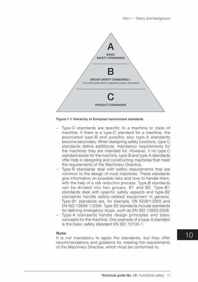
10
Technical guide No. 10 | Functional safety 11
BGROUP SAFETY STANDARDS −
Concrete statements regarding basic standards
CPRODUCT STANDARDS
ABASIC
SAFETY STANDARDS
Figure 1-1 Hierarchy of European harmonized standards
– Type-C standards are specific to a machine or class of machine. If there is a type-C standard for a machine, the associated type- B and possibly also type-A standards become secondary. When designing safety functions, type-C standards define additional, mandatory requirements for the machines they are intended for. However, if no type-C standard exists for the machine, type-B and type-A standards offer help in designing and constructing machines that meet the requirements of the Machinery Directive.
– Type-B standards deal with safety requirements that are common to the design of most machines. These standards give information on possible risks and how to handle them, with the help of a risk reduction process. Type-B standards can be divided into two groups, B1 and B2. Type-B1 standards deal with specific safety aspects and type-B2 standards handle safety-related equipment in general. Type-B1 standards are, for example, EN 62061:2005 and EN ISO 13849-1:2008. Type-B2 standards include standards for defining emergency stops, such as EN ISO 13850:2008.
– Type-A standards handle design principles and basic concepts for the machine. One example of a type-A standard is the basic safety standard EN ISO 12100-1.
Note:It is not mandatory to apply the standards, but they offer recommendations and guidance for meeting the requirements of the Machinery Directive, which must be conformed to.
Part 1 – Theory and background
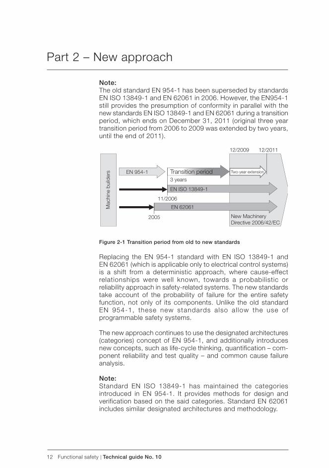
12 Functional safety | Technical guide No. 10
Note:The old standard EN 954-1 has been superseded by standards EN ISO 13849-1 and EN 62061 in 2006. However, the EN954-1 still provides the presumption of conformity in parallel with the new standards EN ISO 13849-1 and EN 62061 during a transition period, which ends on December 31, 2011 (original three year transition period from 2006 to 2009 was extended by two years, until the end of 2011).
EN ISO 13849-1
EN 954-1
EN 62061
Transition period3 years
11/2006
12/2009
2005 New MachineryDirective 2006/42/EC
Mac
hine
bui
lder
s
12/2011
Two-year extension
Figure 2-1 Transition period from old to new standards
Replacing the EN 954-1 standard with EN ISO 13849-1 and EN 62061 (which is applicable only to electrical control systems) is a shift from a deterministic approach, where cause-effect relationships were well known, towards a probabilistic or reliability approach in safety-related systems. The new standards take account of the probability of failure for the entire safety function, not only of its components. Unlike the old standard EN 954-1, these new standards also al low the use of programmable safety systems.
The new approach continues to use the designated architectures (categories) concept of EN 954-1, and additionally introduces new concepts, such as life-cycle thinking, quantification – com-ponent reliability and test quality – and common cause failure analysis.
Note:Standard EN ISO 13849-1 has maintained the categories introduced in EN 954-1. It provides methods for design and verification based on the said categories. Standard EN 62061 includes similar designated architectures and methodology.
Part 2 – New approach
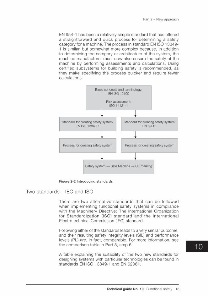
10
Technical guide No. 10 | Functional safety 13
EN 954-1 has been a relatively simple standard that has offered a straightforward and quick process for determining a safety category for a machine. The process in standard EN ISO 13849-1 is similar, but somewhat more complex because, in addition to determining the category or architecture of the system, the machine manufacturer must now also ensure the safety of the machine by performing assessments and calculations. Using certified subsystems for building safety is recommended, as they make specifying the process quicker and require fewer calculations.
Basic concepts and terminology:EN ISO 12100
Risk assessment:ISO 14121-1
Safety system → Safe Machine → CE marking
Process for creating safety system Process for creating safety system
Standard for creating safety system:EN ISO 13849-1
Standard for creating safety system:EN 62061
Figure 2-2 Introducing standards
Two standards – IEC and ISO
There are two alternative standards that can be followed when implementing functional safety systems in compliance with the Machinery Directive: The International Organization for Standardization (ISO) standard and the International Electrotechnical Commission (IEC) standard.
Following either of the standards leads to a very similar outcome, and their resulting safety integrity levels ( SIL) and performance levels ( PL) are, in fact, comparable. For more information, see the comparison table in Part 3, step 6.
A table explaining the suitability of the two new standards for designing systems with particular technologies can be found in standards EN ISO 13849-1 and EN 62061.
Part 2 – New approach
14 Functional safety | Technical guide No. 10
Note:It is up to the machine manufacturer to decide which – if any – safety system creation standard is to be used (EN ISO 13849-1 or EN 62061), and then they must follow the same, chosen standard all the way from beginning to end to ensure congruity with the said standard. CEN standards are based on ISO standards and are basically for mechanical equipment – new standards have numbers in the 10,000 series, while CENELEC standards are based on IEC standards – new standards have numbers in the 60,000 series.
Note:EN ISO standards are presented in this document using the “ISO” mark. However, EN IEC standards are presented without “IEC” mark, according to the convention used in the harmonized standards list.
Standards for risk minimization
Basic safety standards for risk minimization include:
– EN ISO 12100-1:2003 (Safety of machinery – Basic concepts, general principles for design) and
– EN ISO 14121-1:2007 (Safety of machinery – Risk assessment).
EN ISO 12100 gives designers a general framework and guidance, providing a strategy for risk reduction (the three-step method). EN ISO 12100-1 defines the basic terminology and methodology used in achieving machine safety.
EN ISO 14121-1 is a new standard for risk assessment used in the risk reduction process, which is presented in the EN ISO 12100 standard. EN ISO 14121-1 has replaced the EN 1050:1996 standard, which expired on June 24, 2008.
Note:All other references to these standards in this document always apply to the above mentioned versions of the standards.
Standards for electronic safety systems
The standards for electronic safety systems are as follows:
– EN ISO 13849-1:2008 (Safety of machinery – Safety-related parts of control system – Part 1: General Principles for design),
– EN ISO 13849-2:2008 (Safety of machinery – Safety-related parts of control system - Part 2: Validation)
Part 2 – New approach
10
Technical guide No. 10 | Functional safety 15
– EN 62061:2005 (Safety of machinery – Functional safety of safety-related electrical, electronic and programmable elec-tronic control systems),
– IEC 61508 ed. 2.0:2010 (Functional safety of electrical / elec-tronic / programmable electronic safety-related systems), and
– EN 60204-1:2006 (Safety of machinery – Electrical equipment of machines – General requirements).
Note:All other references to these standards in this document always apply to the above mentioned versions of the standards.
EN ISO 13849-1 is a standard that provides instructions to designers to make machines safe. These instructions include recommendations for the design, integration and validation of the systems. It can be used for the safety-related parts of control systems and various kinds of machinery, regardless of the technology and energy it uses. The standard also includes special requirements for safety-related parts that have programmable electronic systems. This standard covers the entire safety function for all devices included (a complete safety chain, for example sensor–logic–actuator).
The standard defines how the required Performance Level ( PL) is determined and the achieved PL verified within a system. PL describes how well a safety system is able to perform a safety function, under foreseeable conditions. There are five possible Performance Levels: a, b, c, d and e. Performance Level “e” has the highest safety reliability, while PL “a” has the lowest.
EN ISO 13849-2 specifies the validation process for safety func-tions designed according to EN ISO 13849-1.
EN 62061 is a standard for designing electrical safety systems. It is a machine sector specific standard within the framework of IEC 61508. EN 62061 includes recommendations for the design, integration and validation of safety-related electrical, electronic and programmable electronic control systems for machinery. The entire safety chain – for example sensor–logic–actuator – is covered by this standard. Individual subsystems need not be certified, as long as the entire safety function fulfills the defined requirements. However, using certified subsystems as building blocks is still strongly recommended, as this will potentially save considerable effort in the design process.
Note:Unlike EN ISO 13849-1, EN 62061 does not cover requirements for non-electrical safety-related control equipment for machinery.
Part 2 – New approach
16 Functional safety | Technical guide No. 10
This standard defines how a Safety Integrity Level ( SIL) is defined. SIL is a representation of the reliability of the safety functions. There are four possible safety integrity levels: 1, 2, 3, and 4. “SIL 4” is the highest level of safety integrity and “SIL 1” the lowest. Only levels 1-3 are used in machinery.
IEC 61508 is a basic functional safety standard. It covers the lifecycle of systems comprised of electrical and/or electronic and/or programmable electronic components that are used to perform safety functions. IEC 61508 is not a harmonized standard, but it is the main standard that outlines the requirements and methods for designing safety related control systems with complex hardware and software. IEC 61508 is generally used when designing certifiable safety subsystems. Standards EN ISO 13849-1 and EN 62061 are based on the principles set in IEC 61508.
EN 60204-1 offers recommendations and requirements for the electrical equipment of machines in order to enhance safety and usability.
Product-specific safety standards (type-C standards)
Product-specific safety standards, known as type-C standards, handle a specific machine or class of machines and are based on a presumption of conformity with respect to the EHSR covered by the standard.
It should be noted that:
– The requirements specified in the type-C standards generally overrule the requirements set by the general safety standards (EN 62061, EN ISO 13849-1, etc.).
– Type-C standards may have set SIL / PL requirements for some safety functions. At least these requirements must be met, regardless of the results of the risk analysis.
Note:Even if the lists of hazards possibly affecting the machine, composed during the risk assessment, and the type-C standard are identical, the standard may not take account of all of the relevant EHSR. The standard must always be inspected thoroughly to determine what hazards might have been excluded from the list.
Specific standard for safety-related drive systems
A specific standard for safety-related drive system is:
– EN 61800-5-2:2007 (Adjustable speed electrical power drive systems - functional safety requirements).
Part 2 – New approach
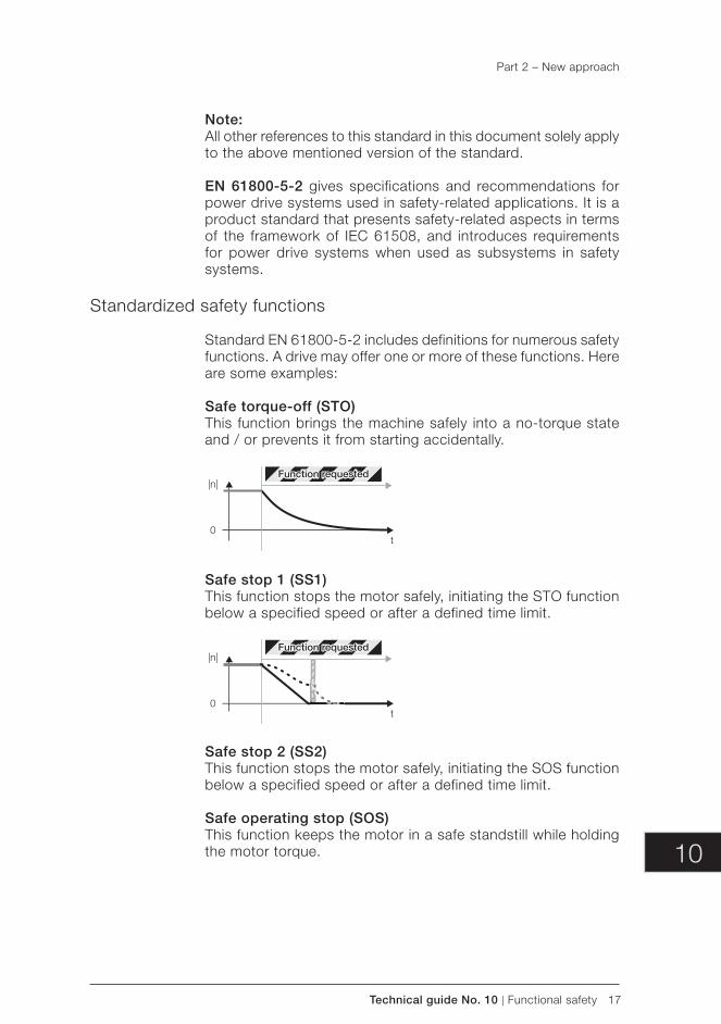
10
Technical guide No. 10 | Functional safety 17
Note:All other references to this standard in this document solely apply to the above mentioned version of the standard.
EN 61800-5-2 gives specifications and recommendations for power drive systems used in safety-related applications. It is a product standard that presents safety-related aspects in terms of the framework of IEC 61508, and introduces requirements for power drive systems when used as subsystems in safety systems.
Standardized safety functions
Standard EN 61800-5-2 includes definitions for numerous safety functions. A drive may offer one or more of these functions. Here are some examples:
Safe torque-off (STO)This function brings the machine safely into a no-torque state and / or prevents it from starting accidentally.
|n|
0t
Function requested
Safe stop 1 (SS1)This function stops the motor safely, initiating the STO function below a specified speed or after a defined time limit.
|n|
0t
Function requested
Safe stop 2 (SS2)This function stops the motor safely, initiating the SOS function below a specified speed or after a defined time limit.
Safe operating stop (SOS)This function keeps the motor in a safe standstill while holding the motor torque.
Part 2 – New approach
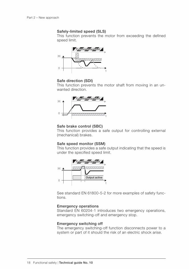
18 Functional safety | Technical guide No. 10
Safely-limited speed (SLS)This function prevents the motor from exceeding the defined speed limit.
|n|
0t
Function requested
Safe direction (SDI)This function prevents the motor shaft from moving in an un-wanted direction.
|n|Function requested
0t
Safe brake control (SBC)This function provides a safe output for controlling external (mechanical) brakes.
Safe speed monitor (SSM)This function provides a safe output indicating that the speed is under the specified speed limit.
|n|
0t
Output active
Function requested
See standard EN 61800-5-2 for more examples of safety func-tions.
Emergency operationsStandard EN 60204-1 introduces two emergency operations, emergency switching-off and emergency stop.
Emergency switching offThe emergency switching-off function disconnects power to a system or part of it should the risk of an electric shock arise.
Part 2 – New approach
10
Technical guide No. 10 | Functional safety 19
This function requires external switching components, and can not be accomplished with drive based functions such as Safe torque-off (STO).
Emergency stopAn emergency stop must operate in such a way that, when it is activated, the hazardous movement of the machinery is stopped and the machine is unable to start under any circumstances, even after the emergency stop is released. Releasing the emergency stop only allows the machine to be restarted.
The emergency stop can stop hazardous movement by applying the following actions: – optimal deceleration rate until the machine stops – by using one of the two emergency stop categories, 0 or 1, or – by employing a predefined shutdown sequence.
Emergency stop category 0 means that the power to the motor is cut off immediately. Stop category 0 is equivalent to the Safe torque-off (STO) function, as defi ned by standard EN 61800-5-2.
Emergency stop category 1 means that the machine speed is brought to a standstill through controlled deceleration and then the power to the motor is cut off. Stop category 1 is equivalent to the Safe Stop 1 (SS1) function, as defi ned by standard EN 61800-5-2.
When actuated, the emergency stop function must not create any additional hazards or require any further involvement by the machine operator.
Note:The principles for the design of an emergency stop function are introduced in standard EN ISO 13850:2008.
Prevention of Unexpected StartupEnsuring that a machine remains stopped when persons are present in danger area is one of the most important conditions in safe machines.
The Safe torque-off (STO) function can be used to effectively implement the prevention of unexpected startup functionality, thus making stops safe by preventing the power only to the motor, while still maintaining power to the main drive control circuits. Prevention of unexpected startup requires for example a lockable switch in addition to the STO function.
The principles and requirements of the prevention of unexpected startup are described in the standard EN 1037:1995+A1.
Part 2 – New approach

20 Functional safety | Technical guide No. 10
The Machinery Directive requires machinery to be safe. However, there is no such thing as zero risk. The objective is to minimize the risk.
Compliance with the Machinery Directive can be achieved:
– by meeting the requirements set by the harmonized standards or
– by having a machine acceptance investigation carried out by an authorized third party.
The process for fulfilling the EHSR of the Machinery Directive using harmonized standards can be divided into nine steps:
– Step 1: Management of functional safety – managing functional safety during the lifecycle of the machine.
– Step 2: Risk assessment – analyzing and evaluating risks. – Step 3: Risk reduction – eliminating or minimizing risks
through design and documentation. – Step 4: Establishing safety requirements – defining what
is needed (functionality, safety performance) to eliminate the risk or reduce it to an acceptable level.
– Step 5: Implementing functional safety system – designing and creating safety functions.
– Step 6: Verifying functional safety system – ensuring that the safety system meets the defined requirements.
– Step 7: Validating functional safety system – returning to the risk assessment process and making certain that the safe-ty system actually succeeded in reducing risks as specified.
– Step 8: Documenting – documenting the design, producing user documentation.
– Step 9: Compliance – proving the machine’s compliance with EHSR of the Machinery Directive through compliance assessment and a technical file.
Each of these steps is explained in more detail in the following chapters.
Updating existing machineryThe following issues must be considered when updating safety requirements for existing machines:
Part 3 – Steps to meet Machinery Directive requirements
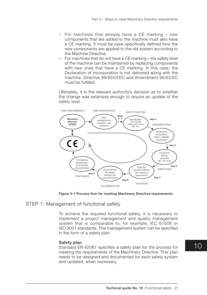
10
Technical guide No. 10 | Functional safety 21
– For machines that already have a CE marking – new components that are added to the machine must also have a CE marking. It must be case-specifically defined how the new components are applied to the old system according to the Machine Directive.
– For machines that do not have a CE marking – the safety level of the machine can be maintained by replacing components with new ones that have a CE marking. In this case, the Declaration of Incorporation is not delivered along with the machine. Directive 89/655/EEC and Amendment 95/63/EC must be fulfilled.
Ultimately, it is the relevant authority’s decision as to whether the change was extensive enough to require an update of the safety level.
MachineryDirective(EHSR)
Risk assessment & evaluation, risk
reduction
Architecture,subsystems,
safety / reliabilityparameters
Functionaltesting,
achievedSIL / PL level
Does thefunction fulfill the
risk reductionrequirement?
Documentingthe design,
residual risk,user instructions
Complianceassessment,technical file,
documentation
Specification- Functionality
- Safety performance(SIL, PLT)
LAWS, REQUIREMENTS RISK IDENTIFICATION
steps 2 - 3 step 4
step 5
step 6
step 7step 8
step 9
SAFETY FUNCTION
IMPLEMENTATION
VERIFICATION
VALIDATIONDOCUMENTATION
COMPLIANCE
Figure 3-1 Process flow for meeting Machinery Directive requirements
STEP 1: Management of functional safety
To achieve the required functional safety, it is necessary to implement a project management and quality management system that is comparable to, for example, IEC 61508 or ISO 9001 standards. This management system can be specified in the form of a safety plan.
Safety planStandard EN 62061 specifies a safety plan for the process for meeting the requirements of the Machinery Directive. This plan needs to be designed and documented for each safety system and updated, when necessary.
Part 3 – Steps to meet Machinery Directive requirements
22 Functional safety | Technical guide No. 10
Safety plan:
– identifies all relevant activities, – describes the policy and strategy for fulfilling functional safety
requirements, – identifies responsibilities, – identifies or establishes procedures and resources for
documentation, – describes strategy for configuration management, and – includes plans for verification and validation.
Note:Even though the activities listed above are not particularly specified in EN ISO 13849-1:2008, similar activities are needed to fully meet the requirements of the Machinery Directive.
When the safety plan (according to EN 62061) has been created, risk assessment starts.
STEP 2: Risk assessment
The risk assessment is a process whereby risks are analyzed and evaluated. A risk is a combination of the consequence of harm and the probability of the harm occurring when exposed to a hazard.
Note:According to the new Machinery Directive 2006/42/EC, it is mandatory to perform a risk assessment for a machine.
The Machinery Directive 2006/42/EC requires that manufacturers perform risk assessments and take the results into account when designing a machine. Any risk considered as “high” must be reduced to an acceptable level using design changes or by applying appropriate safeguarding techniques.
The risk assessment process provides the machinery designer with requirements on how to design inherently safe machinery. It is very important to assess risks at the design phase, because it is generally more effective than providing user instructions on how to operate the equipment safely.
The risk assessment process according to EN ISO 12100-1 con-sists of two parts: risk analysis and risk evaluation. Risk analysis means identifying and estimating the risks and risk evaluation means deciding whether the risk is acceptable or risk reduction necessary.
Part 3 – Steps to meet Machinery Directive requirements

10
Technical guide No. 10 | Functional safety 23
Risk evaluation is carried out based on the results of the risk analysis. Decisions on the necessity of risk reduction are made according to the risk evaluation procedure.
Note:Risk evaluation must be carried out separately for each hazard.
Four steps of risk analysis:1. Determine the limits and intended use of the machine.
These limits include: – limits of use – spatial limits – ambient or environmental limits – lifetime limits
2. Identify the hazards that might be generated by the machine.
3. Estimate identified risks one at a time. – Severity of the risk (potential consequences) – Probability of the risk (Frequency, Probability, Avoidance)
4. Evaluate the risk: Is risk reduction necessary? – YES: Apply risk reduction measures and return to step 2
in the risk analysis.
The 3-step method for risk reduction according to EN ISO 12100-1 is presented in the next chapter.
– NO: Risk reduction target is met and risk assessment process ends.
Document the risk assessment process and its results for each individual hazard.
Part 3 – Steps to meet Machinery Directive requirements
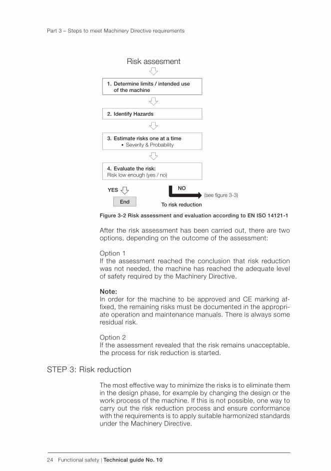
24 Functional safety | Technical guide No. 10
Figure 3-2 Risk assessment and evaluation according to EN ISO 14121-1
After the risk assessment has been carried out, there are two options, depending on the outcome of the assessment:
Option 1If the assessment reached the conclusion that risk reduction was not needed, the machine has reached the adequate level of safety required by the Machinery Directive.
Note:In order for the machine to be approved and CE marking af-fixed, the remaining risks must be documented in the appropri-ate operation and maintenance manuals. There is always some residual risk.
Option 2If the assessment revealed that the risk remains unacceptable, the process for risk reduction is started.
STEP 3: Risk reduction
The most effective way to minimize the risks is to eliminate them in the design phase, for example by changing the design or the work process of the machine. If this is not possible, one way to carry out the risk reduction process and ensure conformance with the requirements is to apply suitable harmonized standards under the Machinery Directive.
Risk assesment
1. Determine limits / intended use of the machine
2. Identify Hazards
3. Estimate risks one at a time Severity & Probability
4. Evaluate the risk: Risk low enough (yes / no)
YES
To risk reduction
NO
End(see figure 3-3)
Part 3 – Steps to meet Machinery Directive requirements
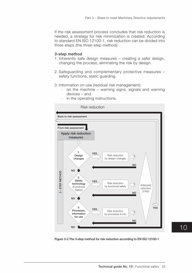
10
Technical guide No. 10 | Functional safety 25
If the risk assessment process concludes that risk reduction is needed, a strategy for risk minimization is created. According to standard EN ISO 12100-1, risk reduction can be divided into three steps (the three-step method):
3-step method1. Inherently safe design measures – creating a safer design,
changing the process, eliminating the risk by design.
2. Safeguarding and complementary protective measures – safety functions, static guarding.
3. Information on use ( residual risk management): – on the machine – warning signs, signals and warning
devices – and – in the operating instructions.
Figure 3-3 The 3-step method for risk reduction according to EN ISO 12100-1
Back to risk assessment
From risk assessment
Risk reduction
YES
3 -
ST
EP
ME
TH
OD
Apply risk reduction measures
NO
NO
Risk reductionby design changes
Risk reductionby functional safety
Risk reductionby processes & info
YES
YES
YES
NO
NO
NO
NO
Adequatereduction
(Y/N)?
1.Design
changes
2.Safety
technology(Functional
Safety)
3.Processes,information
for use
?
?
?
Part 3 – Steps to meet Machinery Directive requirements
26 Functional safety | Technical guide No. 10
Residual risk is the risk that remains when all protective measures have been considered and implemented. Using technology, it is not possible to achieve a state of zero risk, since some residual risk always remains.
All residual r isks must be documented in the operating instructions.
The user’s part of risk reduction includes information given by the designer (manufacturer). Risk reduction measures for the machine user / organization are as follows:
– Risk reduction measures typically taken by the organization:
– introducing safe working procedures – work supervision – permit-to-work systems
– Provision and use of additional safeguards – Use of personal protective equipment – Training users – Reading operating and safety instructions and acting accord-
ingly.
Designers should also seek valuable user input when defining protective measures.
When the risk reduction has been executed, it must be examined to ensure that the measures taken were adequate for reducing the risk to an appropriate level. This can be done by repeating the risk assessment process.
The following, remaining steps describe option 2 of the 3-step method: safeguarding through a functional safety solution.
STEP 4: Establishing safety requirements
After all the risk reduction that can be undertaken through design changes has been performed, additional safeguarding needs to be specified. Functional safety solutions can be used against the remaining hazards as an additional risk reduction measure.
Safety functionsA safety function is a function of a machine whose failure can result in an immediate increase in risk. Simply put, it comprises the measures that must be taken to reduce the likelihood of an unwanted event occurring during exposure to a hazard. A safety function is not part of machine operation itself. This means that if the safety function fails, the machine can operate normally, but the risk of injury from machine operation increases.
Part 3 – Steps to meet Machinery Directive requirements
10
Technical guide No. 10 | Functional safety 27
Defining a safety function always includes two components:
– required action (what must be done to reduce the risk) and – safety performance (Safety Integrity Level - SIL or
Performance Level - PL).
Note:A safety function must be specified, verified (functionality and safety performance) and validated separately for each identified hazard.
Example of a safety function:Requirement: An exposed rotating shaft may cause an injury if one gets too close to the shaft.
Action: In order to prevent personal injury from the shaft, the mo-tor must stop in one (1) second, when the safety gate is opened.
After the safety function that executes the action has been defined, the required safety level is determined for it.
Safety performance / integritySafety integrity measures the performance of a safety function. It presents the likelihood of the safety function being achieved, upon request. The required safety integrity for a function is de-termined during the risk assessment and is represented by the achieved Safety Integrity Level (SIL) or Performance Level (PL), depending on the standard used.
The two standards use different evaluation techniques for a safety function, but their results are comparable. The terms and definitions are similar for both standards.
Determining the required SIL ( EN 62061)The process for determining the required safety integrity level (SIL) is as follows:
1. Determine the severity of the consequence of a hazardous event.
2. Determine the point value for the frequency and duration a person is exposed to the harm.
3. Determine the point value for the probability of the hazardous event occurring when exposed to it.
4. Determine the point value for the possibility of preventing or limiting the scope of the harm.
Example:The parameters used in determining the point values are presented in the following example of an SIL assignment table.
Part 3 – Steps to meet Machinery Directive requirements
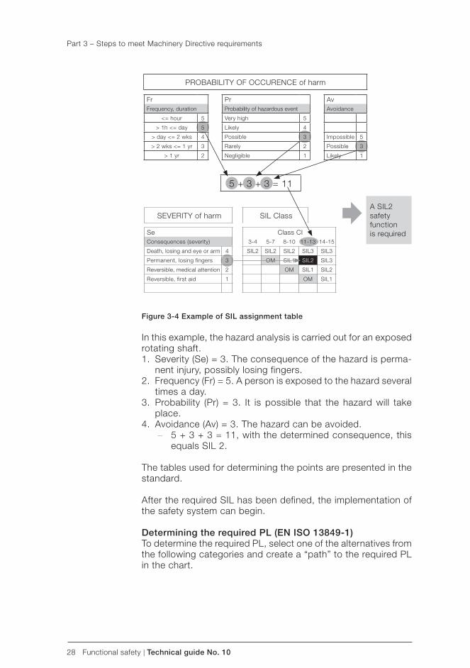
28 Functional safety | Technical guide No. 10
Figure 3-4 Example of SIL assignment table
In this example, the hazard analysis is carried out for an exposed rotating shaft.1. Severity (Se) = 3. The consequence of the hazard is perma-
nent injury, possibly losing fingers.2. Frequency (Fr) = 5. A person is exposed to the hazard several
times a day.3. Probability (Pr) = 3. It is possible that the hazard will take
place.4. Avoidance (Av) = 3. The hazard can be avoided.
– 5 + 3 + 3 = 11, with the determined consequence, this equals SIL 2.
The tables used for determining the points are presented in the standard.
After the required SIL has been defined, the implementation of the safety system can begin.
Determining the required PL ( EN ISO 13849-1)To determine the required PL, select one of the alternatives from the following categories and create a “path” to the required PL in the chart.
SIL Class
Class CI3-4 5-7 8-10 11-13 14-15
SIL2 SIL2 SIL2 SIL3 SIL3
OM SIL1 SIL2 SIL3
OM SIL1 SIL2
OM SIL1
FrFrequency, duration
<= hour 5
> 1h <= day 5
> day <= 2 wks 4
> 2 wks <= 1 yr 3
> 1 yr 2
AvAvoidance
Impossible 5
Possible 3
Likely 1
PrProbability of hazardous event
Very high 5
Likely 4
Possible 3
Rarely 2
Negligible 1
PROBABILITY OF OCCURENCE of harm
5 + 3 + 3 = 11
A SIL2safety functionis required
SEVERITY of harm
SeConsequences (severity)
Death, losing and eye or arm 4
Permanent, losing fingers 3
Reversible, medical attention 2
Reversible, first aid 1
Part 3 – Steps to meet Machinery Directive requirements
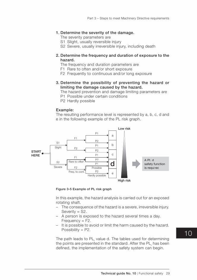
10
Technical guide No. 10 | Functional safety 29
1. Determine the severity of the damage.The severity parameters areS1 Slight, usually reversible injuryS2 Severe, usually irreversible injury, including death
2. Determine the frequency and duration of exposure to the hazard.The frequency and duration parameters areF1 Rare to often and/or short exposureF2 Frequently to continuous and/or long exposure
3. Determine the possibility of preventing the hazard or limiting the damage caused by the hazard.The hazard prevention and damage limiting parameters areP1 Possible under certain conditionsP2 Hardly possible
Example:The resulting performance level is represented by a, b, c, d and e in the following example of the PL risk graph.
STARTHERE
High risk
Low risk
S1
Slight
S2
Severe
F1
Rare to often
Possible
Hardly possible
F2
F1
F2
P2
P1
P2
P2
P2
P1
P1
P1
Freq. to cont.
a
b
c
e
dS2
Severe
F1
Rare to often
PossibleF2P2
P1
P2
P1
Figure 3-5 Example of PL risk graph
In this example, the hazard analysis is carried out for an exposed rotating shaft. – The consequence of the hazard is a severe, irreversible injury.
Severity = S2. – A person is exposed to the hazard several times a day.
Frequency = F2. – It is possible to avoid or limit the harm caused by the hazard.
Possibility = P2.
The path leads to PLr value d. The tables used for determining the points are presented in the standard. After the PLr has been defined, the implementation of the safety system can begin.
Part 3 – Steps to meet Machinery Directive requirements
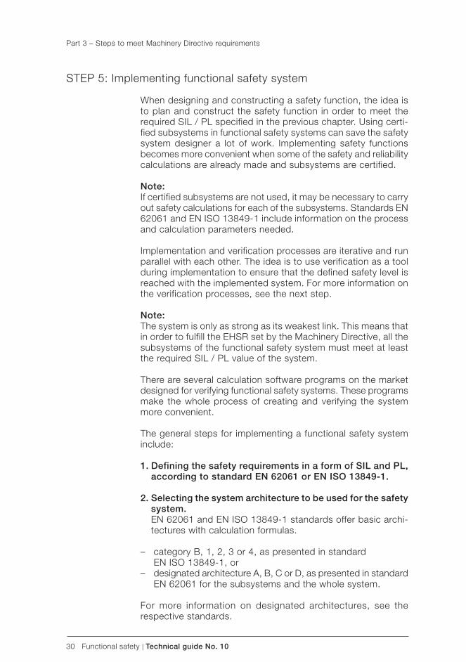
30 Functional safety | Technical guide No. 10
STEP 5: Implementing functional safety system
When designing and constructing a safety function, the idea is to plan and construct the safety function in order to meet the required SIL / PL specified in the previous chapter. Using certi-fied subsystems in functional safety systems can save the safety system designer a lot of work. Implementing safety functions becomes more convenient when some of the safety and reliability calculations are already made and subsystems are certified.
Note:If certified subsystems are not used, it may be necessary to carry out safety calculations for each of the subsystems. Standards EN 62061 and EN ISO 13849-1 include information on the process and calculation parameters needed.
Implementation and verification processes are iterative and run parallel with each other. The idea is to use verification as a tool during implementation to ensure that the defined safety level is reached with the implemented system. For more information on the verification processes, see the next step.
Note:The system is only as strong as its weakest link. This means that in order to fulfill the EHSR set by the Machinery Directive, all the subsystems of the functional safety system must meet at least the required SIL / PL value of the system.
There are several calculation software programs on the market designed for verifying functional safety systems. These programs make the whole process of creating and verifying the system more convenient.
The general steps for implementing a functional safety system include:
1. Defining the safety requirements in a form of SIL and PL, according to standard EN 62061 or EN ISO 13849-1.
2. Selecting the system architecture to be used for the safety system.EN 62061 and EN ISO 13849-1 standards offer basic archi-tectures with calculation formulas.
– category B, 1, 2, 3 or 4, as presented in standard EN ISO 13849-1, or
– designated architecture A, B, C or D, as presented in standard EN 62061 for the subsystems and the whole system.
For more information on designated architectures, see the respective standards.
Part 3 – Steps to meet Machinery Directive requirements
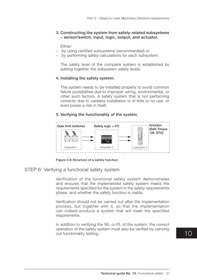
10
Technical guide No. 10 | Functional safety 31
3. Constructing the system from safety-related subsystems – sensor/switch, input, logic, output, and actuator.
Either: – by using certified subsystems (recommended) or – by performing safety calculations for each subsystem.
The safety level of the complete system is established by adding together the subsystem safety levels.
4. Installing the safety system.
The system needs to be installed properly to avoid common failure possibilities due to improper wiring, environmental, or other such factors. A safety system that is not performing correctly due to careless installation is of little or no use, or even poses a risk in itself.
5. Verifying the functionality of the system.
Gate limit switches
Subsystem 1
Safety logic + I/O
Subsystem 2
Actuator(Safe Torque Off, STO)
Subsystem 3
Figure 3-6 Structure of a safety function
STEP 6: Verifying a functional safety system
Verification of the functional safety system demonstrates and ensures that the implemented safety system meets the requirements specified for the system in the safety requirements phase, and whether the safety function is viable.
Verification should not be carried out after the implementation process, but together with it, so that the implementation can indeed produce a system that will meet the specified requirements.
In addition to verifying the SIL or PL of the system, the correct operation of the safety system must also be verified by carrying out functionality testing.
Part 3 – Steps to meet Machinery Directive requirements
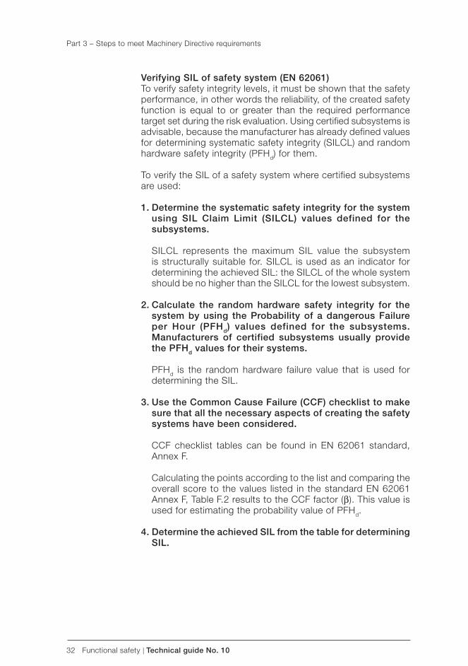
32 Functional safety | Technical guide No. 10
Verifying SIL of safety system (EN 62061)To verify safety integrity levels, it must be shown that the safety performance, in other words the reliability, of the created safety function is equal to or greater than the required performance target set during the risk evaluation. Using certified subsystems is advisable, because the manufacturer has already defined values for determining systematic safety integrity (SILCL) and random hardware safety integrity (PFHd) for them.
To verify the SIL of a safety system where certified subsystems are used:
1. Determine the systematic safety integrity for the system using SIL Claim Limit (SILCL) values defined for the subsystems.
SILCL represents the maximum SIL value the subsystem is structurally suitable for. SILCL is used as an indicator for determining the achieved SIL: the SILCL of the whole system should be no higher than the SILCL for the lowest subsystem.
2. Calculate the random hardware safety integrity for the system by using the Probability of a dangerous Failure per Hour (PFHd) values defined for the subsystems. Manufacturers of certified subsystems usually provide the PFHd values for their systems.
PFHd is the random hardware failure value that is used for determining the SIL.
3. Use the Common Cause Failure (CCF) checklist to make sure that all the necessary aspects of creating the safety systems have been considered.
CCF checklist tables can be found in EN 62061 standard, Annex F.
Calculating the points according to the list and comparing the overall score to the values listed in the standard EN 62061 Annex F, Table F.2 results to the CCF factor (β). This value is used for estimating the probability value of PFHd.
4. Determine the achieved SIL from the table for determining SIL.
Part 3 – Steps to meet Machinery Directive requirements
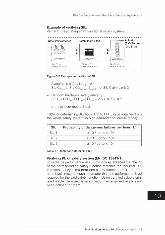
10
Technical guide No. 10 | Functional safety 33
Example of verifying SIL:Verifying the rotating shaft functional safety system:
SIL CL = 2PFHd = 2,4 x 10⁻⁷
SIL CL = 3PFHd = 9,8 x 10⁻⁹
SIL CL = 3PFHd = 2,0 x 10⁻¹⁰
Gate limit switches
Subsystem 1
Safety logic + I/O
Subsystem 2
Actuator(Safe Torque Off, STO)
Subsystem 3
Figure 3-7 Example verification of SIL
– Systematic safety integrity: SIL CLsys ≤ (SIL CLsubsystem)lowest -> SIL Claim Limit 2
– Random hardware safety integrity: PFHd = PFHd1+PFHd2+PFHd3 = 2,5 x 10⁻⁷ < 10-6
= the system meets SIL 2.
Table for determining SIL according to PFHd value obtained from the whole safety system (in high demand/continuous mode):
SIL Probability of dangerous failures per hour (1/h)
SIL 1 ≥ 10-6 up to < 10-5
SIL 2 ≥ 10-7 up to < 10-6
SIL 3 ≥ 10-8 up to < 10-7
Table 3-1 Table for determining SIL
Verifying PL of safety system ( EN ISO 13849-1)To verify the performance level, it must be established that the PL of the corresponding safety function matches the required PLr. If several subsystems form one safety function, their perform-ance levels must be equal or greater than the performance level required for the said safety function. Using certified subsystems is advisable, because the safety performance values have already been defined for them.
Part 3 – Steps to meet Machinery Directive requirements
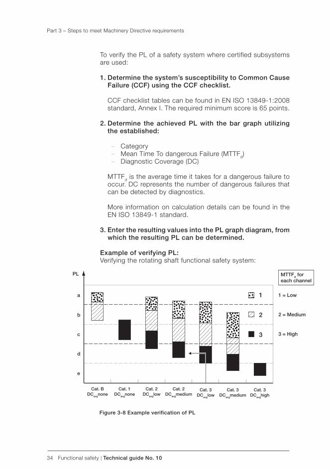
34 Functional safety | Technical guide No. 10
1 = Low
2 = Medium
3 = High
PL
a
b
c
d
e
Cat. BDCavgnone
Cat. 1DCavgnone
Cat. 2DCavglow
Cat. 3DCavglow
Cat. 3DCavgmedium
Cat. 3DCavghigh
Cat. 2DCavgmedium
1
2
3
MTTFd foreach channel
To verify the PL of a safety system where certified subsystems are used:
1. Determine the system’s susceptibility to Common Cause Failure (CCF) using the CCF checklist.
CCF checklist tables can be found in EN ISO 13849-1:2008 standard, Annex I. The required minimum score is 65 points.
2. Determine the achieved PL with the bar graph utilizing the established:
– Category – Mean Time To dangerous Failure (MTTFd) – Diagnostic Coverage (DC)
MTTFd is the average time it takes for a dangerous failure to occur. DC represents the number of dangerous failures that can be detected by diagnostics.
More information on calculation details can be found in the EN ISO 13849-1 standard.
3. Enter the resulting values into the PL graph diagram, from which the resulting PL can be determined.
Example of verifying PL:Verifying the rotating shaft functional safety system:
Figure 3-8 Example verification of PL
Part 3 – Steps to meet Machinery Directive requirements
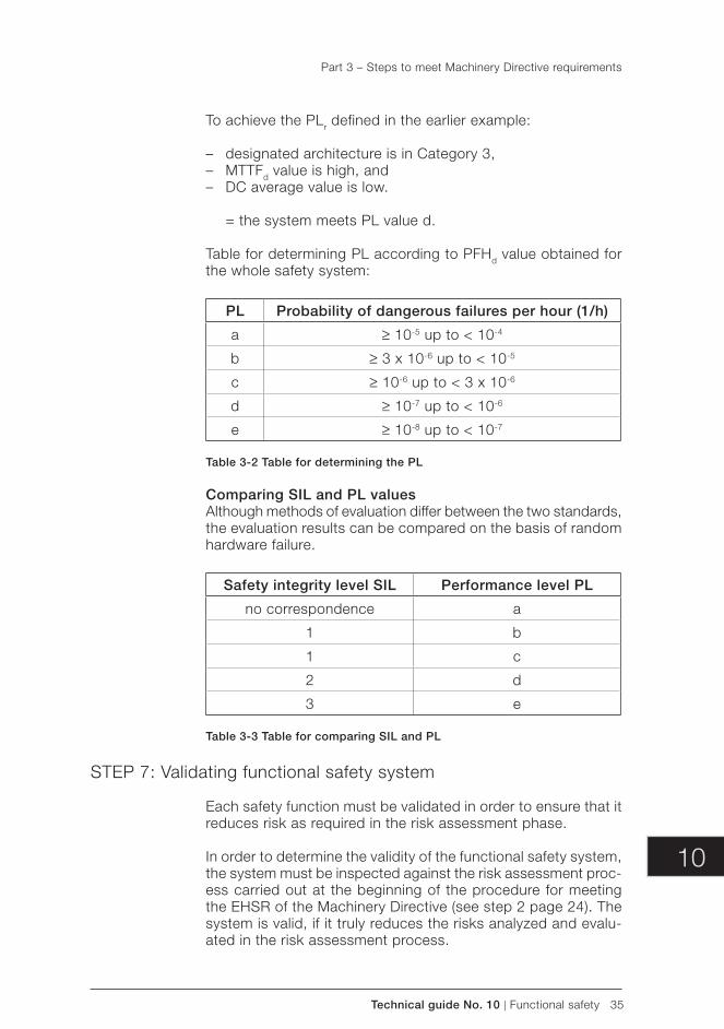
10
Technical guide No. 10 | Functional safety 35
To achieve the PLr defined in the earlier example:
– designated architecture is in Category 3, – MTTFd value is high, and – DC average value is low.
= the system meets PL value d.
Table for determining PL according to PFHd value obtained for the whole safety system:
PL Probability of dangerous failures per hour (1/h)
a ≥ 10-5 up to < 10-4
b ≥ 3 x 10⁻⁶ up to < 10-5
c ≥ 10-6 up to < 3 x 10⁻⁶
d ≥ 10-7 up to < 10-6
e ≥ 10-8 up to < 10-7
Table 3-2 Table for determining the PL
Comparing SIL and PL valuesAlthough methods of evaluation differ between the two standards, the evaluation results can be compared on the basis of random hardware failure.
Safety integrity level SIL Performance level PL
no correspondence a
1 b
1 c
2 d
3 e
Table 3-3 Table for comparing SIL and PL
STEP 7: Validating functional safety system
Each safety function must be validated in order to ensure that it reduces risk as required in the risk assessment phase.
In order to determine the validity of the functional safety system, the system must be inspected against the risk assessment proc-ess carried out at the beginning of the procedure for meeting the EHSR of the Machinery Directive (see step 2 page 24). The system is valid, if it truly reduces the risks analyzed and evalu-ated in the risk assessment process.
Part 3 – Steps to meet Machinery Directive requirements
36 Functional safety | Technical guide No. 10
STEP 8: Documenting functional safety system
The design of the machine must be documented and relevant user documentation produced before the machine fulfills the requirements set in the Machinery Directive.
Documentation needs to be carefully produced to serve its purpose. It has to be accurate and concise, but at the same time informative and easy for the user to understand. All residual risk must be documented in the user documentation, with proper instructions on how to operate the machine safely. The documentation must be accessible and maintainable. The user documentation is delivered with the machine.
For more information on the documentation required and its nature, see the EHSR in Annex I of the Machinery Directive.
STEP 9: Proving compliance
Before a machine can be placed on the market, the manufacturer must ensure that the machine is implemented in conformance with harmonized standards. It must also be proved that the combination for each safety function of the safety-related parts meets the defined requirements.
To prove the conformance with the Machinery Directive, it must be shown that:
– Machinery fulfills the relevant Essential Health and Safety Requirements ( EHSR) defined in the Machinery Directive.
– Machinery fulfills the requirements of other possible Directives related to it.
– Conformity with these requirements can be ensured by following the relevant harmonized standards.
– The technical file is up-to-date and available.The technical fi le demonstrates that the machine is in accordance with the regulations presented in the Machinery Directive.
Note:A missing technical file could provide reason to doubt the machine’s compliance with the EHSR.
Part 3 – Steps to meet Machinery Directive requirements

10
Technical guide No. 10 | Functional safety 37
The technical file should cover the design, manufacture and operation of the machinery in so far as necessary to demonstrate compliance. For more information on the contents of the technical file, see Annex VII of the Machinery Directive 2006/42/EC.
– Conformity assessment procedures have been applied.Special requirements for machines listed in the Machinery Directive’s Annex IV are met, where appropriate.
– The EC declaration of conformity has been produced and is delivered with the machine.
Once conformity has been established, a CE marking is affixed.
Machinery that carries CE markings and is accompanied by an EC declaration of conformity is presumed to comply with the requirements of the Machinery Directive.
Part 3 – Steps to meet Machinery Directive requirements

38 Functional safety | Technical guide No. 10
CE markingA mandatory conformity mark on machinery and many other kinds of products placed on the single market in the European Economic Area (EEA). By affixing CE marking to the product, the manufacturer ensures that the product meets all of the essential requirements of the relevant European Directive(s).
CCF, Common Cause FailureA situation where several subsystems fail due to a single event. All failures are caused by the event itself and are not conse-quences of each other.
DC, Diagnostic CoverageDiagnostic Coverage (DC) is the effectiveness of fault monitoring of a system or subsystem. It is the ratio between the failure rate of detected dangerous failures and the failure rate of total dangerous failures.
EHSR, Essential Health and Safety RequirementsRequirements that machinery must meet in order to comply with the European Union Machinery Directive and obtain CE mark-ing. These requirements are listed in the Machinery Directive’s Annex I.
ENStands for “EuroNorm”. This prefix is used with harmonized standards.
HarmPhysical injury or damage to health.
Harmonized standardA European standard that has been prepared under the mandate of the European Commission or the EFTA Secretariat with the purpose of supporting the essential requirements of a directive and is effectively mandatory under the EU law.
HazardPotential source of harm.
IEC, International Electrotechnical CommissionA worldwide organization for standardization that consists of all national electrotechnical committees.www.iec.ch
Glossary

10
Technical guide No. 10 | Functional safety 39
ISO, International Organization for StandardizationA worldwide federation of national standards member bodies.www.iso.org
MTTFd, Mean Time To dangerous FailureExpectation of the average time for a dangerous failure to occur.
PFHd, Probability of dangerous Failure per HourAverage probability of dangerous failure taking place during one (1) hour. PFHd is the value that is used for determining the SIL or PL value of a safety function.
PL, Performance LevelLevels (a, b, c, d, e) for specifying the capability of a safety system to perform a safety function under foreseeable conditions.
PLr
Required Performance Level (based on the risk evaluation).
RiskA combination of how possible it is for the harm to happen and how severe the harm would be.
Safety functionA function designed for adding safety to a machine whose failure can result in an immediate increase in risk(s).
SIL, Safety Integrity LevelLevels (1, 2, 3, 4) for specifying the capability of an electrical safety system to perform a safety function under foreseeable conditions. Only levels 1-3 are used in machinery.
SILCL, SIL Claim LimitMaximum safety integrity level (SIL) that can be claimed for an electrical safety system, taking account of architectural constraints and systematic safety integrity.
SubsystemA component of a safety function that has its own safety level (SIL /PL) that affects the safety level of the whole safety func-tion. If any of the subsystems fail, the whole safety function fails.
Glossary
40 Functional safety | Technical guide No. 10
Index
AAnnex IV 11, 12, 39
CCE marking 7, 10, 23, 26, 39, 40CEN 12, 16CENELEC 12, 16
Ddocumenting safety system 38
EEHSR 8, 9, 10, 18, 22, 32, 37, 38, 40emergency stop 13, 21emergency switching off 20EN 61800-5-2 18EN 62061 13, 14, 16, 24, 29, 32, 34EN ISO 13849-1 13, 14, 16, 24, 30, 32, 35
Ffunctional safety 9, 23, 28functional safety system 32, 33, 37
Hharmonized standards 8, 12, 16, 22, 26, 38
IIEC, International Electrotechnical Commission 15, 40ISO, International Organization for Standardization 15, 41
MMachinery Directive 8, 9, 11, 12, 22, 24, 26, 32, 37, 38Machinery Directive 2006/42/EC 11, 24, 38Machinery Directive 98/37/EC 11, 39
PPL, Performance Level 15, 17, 29, 30, 35, 37, 41proving compliance 40
Rresidual risk 26, 27, 28, 38risk analysis 10, 18, 24, 25risk assessment 12, 16, 18, 24, 26, 27, 29, 37risk reduction 9, 13, 16, 24, 25, 26
Ssafe brake control (SBC) 21safe direction (SDI) 20safely-limited speed (SLS) 19safe operating stop (SOS) 19safe speed monitor (SSM) 20safe stop 1 (SS1) 19safe stop 2 (SS2) 19safety functions 9, 10, 13, 14, 17, 18, 19, 27, 28, 32, 33, 37, 38, 41safety performance 8, 10, 29, 34, 35safety plan 23SIL, Safety Integrity Level 15, 17, 29, 34, 37, 41
Ttransition period 14type-A standards 13type-B standards 13type-C standards 13
Uupdating existing machinery 22
Vvalidating safety system 39verifying safety system 35

10
Technical guide No. 10 | Functional safety 41

3AU
A00
0004
8753
RE
V D
EN
30.
3.20
11 #
1551
1
Contact us
For more information contact your local ABB representative or visit:
www.abb.com/driveswww.abb.com/drivespartners
© Copyright 2011 ABB. All rights reserved. Specifications subject to change without notice.


3AFE
6451
4482
RE
V G
EN
11.
2.20
13 #
1664
6
Contact us
© Copyright 2013 ABB. All rights reserved. Specifications subject to change without notice.
For more information please contact your local ABB representative or visit:
www.abb.com/driveswww.abb.com/drivespartners