Embed Size (px)
Citation preview
Revised on : 06. Feb. 2018
SII Products
TECHNICAL GUIDE
&
PARTS CATALOGUE
Cal. NH1*A
AUTOMATIC MECHANICAL
[SPECIFICATION]
SII Products 1
Time settingSecond click Time setting
Crown
position Date setting NH15A:Free NH16A:Day setting
Counterclockwise Clockwise
First click
Duration timeMore than 40 hours … Mainspring after fully wound up.
* Posture to confirmation : Dial up
20 seconds
* Equipment to be used : Witschi WATCH EXPERT
Posture
difference
Difference is under 90 seconds within max value and min value.
* Measurement should be done within 10~60 minutes after fully wound up.
* Direction of 4 positions.
(1) 12 o'clock up (2) 9 o'clock up (3) 6 o'clock up (4) 3 o'clock up
Isochronisms
(24h-0h)
Measurement
time
-35~+35 seconds per day.
* Direction of position. : Dial up
* Difference of static accuracy of 24h and 0h
Winding the mainspring
Normal position Free Manual winding
<< Movements >>・Fully wound up by turning the crown minimum 55 times.
<< Complete Watch >>
A winding machine is needed to wind up the mainspring.
Full wind up conditions・Rotary speed : 30 rpm・Operating time: 60 minutes
Jewels 21 jewels
Basic function
Frequency 21,600 vibrations per hour
Accuracy
Static accuracy
-35~+55 seconds per day
* Measurement should be done within 10~60 minutes after fully wound up.
* All measurements are made without the calendar in function.Measurement
positionDirection of 3 positions. (1) Dial up (2) 9 o'clock up (3) 6 o'clock up
Lift angle 52 deg.
Manual winding
Automatic winding with ball bearing
Quick date correction
Manual winding
Automatic winding with ball bearing
Quick day-date correction
Item
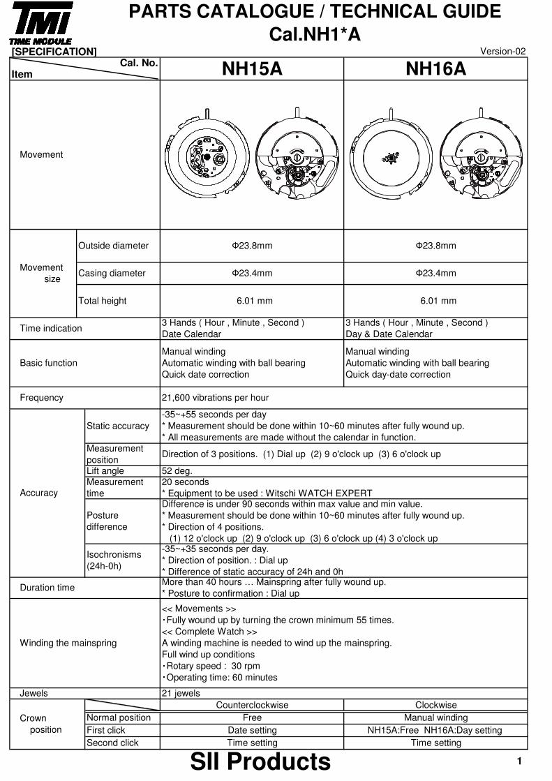
Movement
Movement size
Outside diameter
PARTS CATALOGUE / TECHNICAL GUIDE
Cal.NH1*AVersion-02
Cal. No. NH15A NH16A
Ф23.8mm
Ф23.4mm
6.01 mm 6.01 mm
Ф23.4mm
Ф23.8mm
Time indication
Casing diameter
Total height
3 Hands ( Hour , Minute , Second )
Date Calendar
3 Hands ( Hour , Minute , Second )
Day & Date Calendar
Type of oil Oil quantity mark
Moebius 9010
S-6
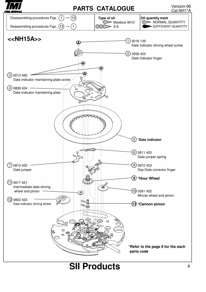
0016 139
Date indicator driving wheel screw
0556 423
Date indicator finger
0012 485
Date indicator maintaining plate screw
0808 424
Date indicator maintaining plate
*Date indicator
0811 420
Date jumper spring
0810 420 0972 423
Date jumper Day-Date corrector finger
*Hour Wheel0817 421
Intermediate date driving
wheel and pinion 0261 422
Minute wheel and pinion
0802 423
*Cannon pinion
*Refer to the page 8 for the each
parts code
Date indicator driving wheel
2
2SII Products
5
6
8
9
10
3
→1
13
4
12
7
11
<<NH15A>>
NORMAL QUANTITY
Reassembling procedures Figs.
Version-06Cal.NH1*APARTS CATALOGUE
1 → 13Disassembling procedures Figs.
1 SUFFICIENT QUANTITY13
Type of oil Oil quantity mark
Moebius 9010
S-6
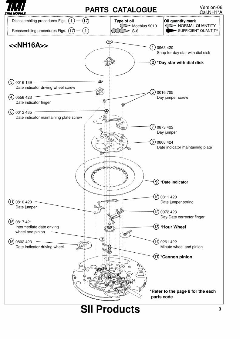
0963 420
Snap for day star with dial disk
*Day star with dial disk
0016 139
Date indicator driving wheel screw
0016 705
0556 423 Day jumper screw
Date indicator finger
0012 485
Date indicator maintaining plate screw
0873 422
Day jumper
0808 424
Date indicator maintaining plate
*Date indicator
0811 420
0810 420 Date jumper spring
Date jumper
0972 423
Day-Date corrector finger
0817 421
Intermediate date driving *Hour Wheelwheel and pinion
0802 423 0261 422
Date indicator driving wheel Minute wheel and pinion
*Cannon pinion
15
1416
17
9
11
10
*Refer to the page 8 for the each
parts code
12
13
SII Products 3
6
5
7
8
NORMAL QUANTITY
SUFFICIENT QUANTITY
1
2
3
4
17 → 1Reassembling procedures Figs.
<<NH16A>>
Version-06PARTS CATALOGUE Cal.NH1*A
Disassembling procedures Figs. 1 → 17
Type of oil Oil quantity mark
Moebius 9010
S-6
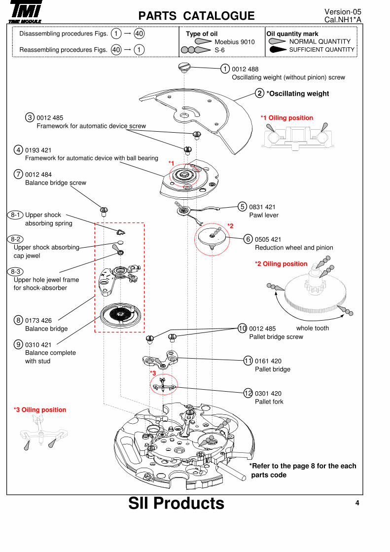
0012 488
Oscillating weight (without pinion) screw
*Oscillating weight
0012 485 *1 Oiling position
Framework for automatic device screw
0193 421
0012 484
Balance bridge screw
0831 421
Pawl lever
absorbing spring
0505 421
Reduction wheel and pinion
cap jewel
*2 Oiling position
0173 426
Balance bridge 0012 485
Pallet bridge screw
0310 421
with stud 0161 420
Pallet bridge
0301 420
Pallet fork
*3 Oiling position
*Refer to the page 8 for the each
parts code
9
10
11
12
Balance complete
8
1
3
2
4Framework for automatic device with ball bearing
7
5
Upper shock absorbing
Upper hole jewel frame
for shock-absorber
8-1
68-2
8-3
1→ Version-05
4SII Products
PARTS CATALOGUE→ Cal.NH1*A
Disassembling procedures Figs. 1 40NORMAL QUANTITY
SUFFICIENT QUANTITYReassembling procedures Figs. 40
Upper shock
whole tooth
*2
*1
*3
Type of oil Oil quantity markMoebius 9010 S-6 NORMAL QUANTITY
SUFFICIENT QUANTITY
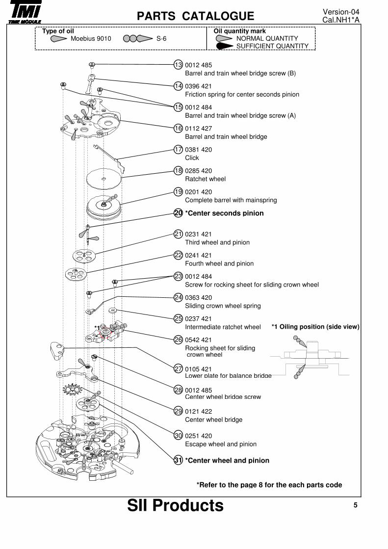
0012 485
Barrel and train wheel bridge screw (B)
0396 421
Friction spring for center seconds pinion
0012 484
Barrel and train wheel bridge screw (A)
0112 427
Barrel and train wheel bridge
0381 420
Click
0285 420
Ratchet wheel
0201 420
Complete barrel with mainspring
*Center seconds pinion
0231 421
Third wheel and pinion
0241 421
Fourth wheel and pinion
0012 484
Screw for rocking sheet for sliding crown wheel
0363 420
Sliding crown wheel spring
0237 421
Intermediate ratchet wheel
0542 421
Rocking sheet for sliding crown wheel
0105 421Lower plate for balance bridge
0012 485Center wheel bridge screw
0121 422
Center wheel bridge
0251 420
Escape wheel and pinion
*Center wheel and pinion
*Refer to the page 8 for the each parts code
5SII Products
17
15
16
18
19
21
22
20
25
24
23
*1 Oiling position (side view)
30
27
28
29
31
26
Version-04Cal.NH1*APARTS CATALOGUE
14
13
*1
Type of oil Oil quantity markMoebius 9010 S-6 NORMAL QUANTITY
SUFFICIENT QUANTITY
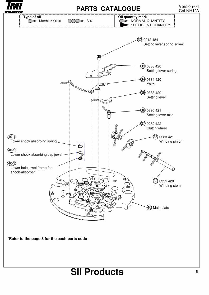
0012 484
Setting lever spring screw
0388 420
Setting lever spring
0384 420
Yoke
0383 420
Setting lever
0390 421
Setting lever axle
0282 422
Clutch wheel
0283 421
Winding pinion
0351 420
Winding stem
Main plate
*Refer to the page 8 for the each parts code
37
38
39
Lower shock absorbing spring
Lower shock absorbing cap jewel
Lower hole jewel frame for
shock-absorber
40
40-1
40-2
40-3
6SII Products
35
36
Version-04Cal.NH1*APARTS CATALOGUE
32
33
34
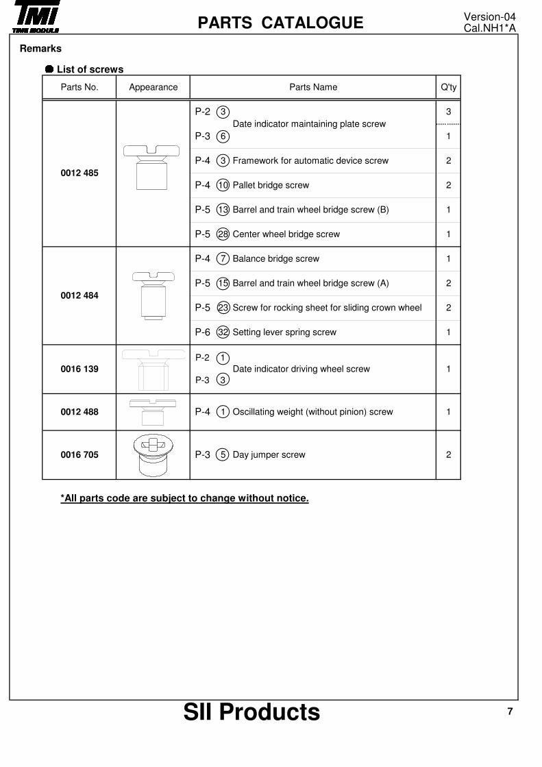
Remarks●●●● List of screws
*All parts code are subject to change without notice.
Center wheel bridge screwP-5
P-3
P-4
7SII Products
23
32 Setting lever spring screw
Oscillating weight (without pinion) screw
Day jumper screw
Date indicator driving wheel screw
P-5 2
Barrel and train wheel bridge screw (A)
P-6 1
Screw for rocking sheet for sliding crown wheel
Version-04Cal.NH1*APARTS CATALOGUE
15
7
Appearance
0012 484
Q'ty
28
Parts No.
0012 485
Framework for automatic device screw
13
10 Pallet bridge screw
Barrel and train wheel bridge screw (B)
0016 139
P-3 5 2
1
P-2
P-3
1
1
3
0012 488
0016 705
P-4 1
P-4 1Balance bridge screw
P-5 2
1
P-4
P-5
2
1
2
P-2
3
Parts Name
3
6
3
1
Date indicator maintaining plate screw
Remarks
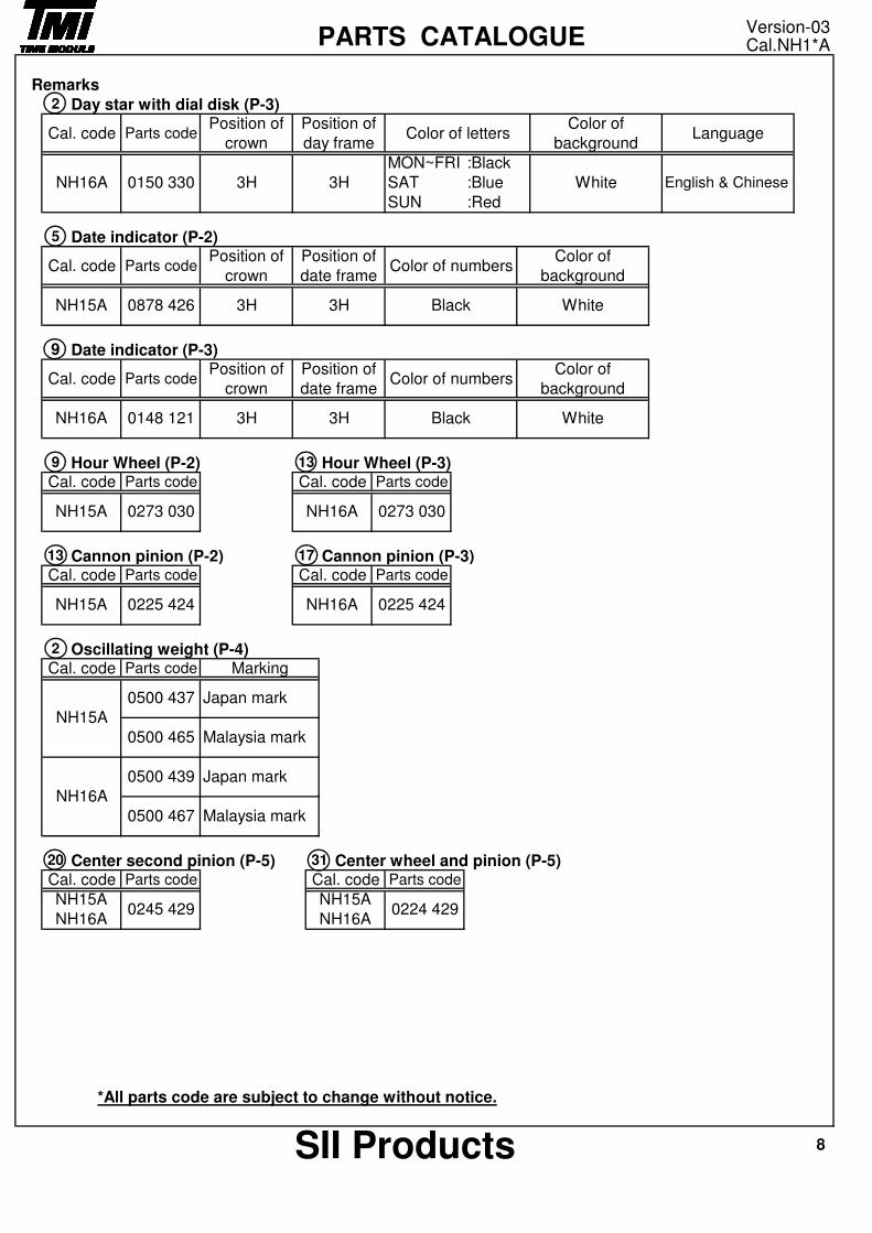
Day star with dial disk (P-3)
Date indicator (P-2)
Date indicator (P-3)
Hour Wheel (P-2) Hour Wheel (P-3)
Cannon pinion (P-2) Cannon pinion (P-3)
Oscillating weight (P-4)
Center second pinion (P-5) Center wheel and pinion (P-5)
*All parts code are subject to change without notice.
9
2
Parts code
NH16A
Parts code
17
NH15A 0225 424
Parts code
NH15A
NH16A
NH15A 0878 426 3H3H
13
0273 030 NH16A 0273 030
Position of
crown
Position of
date frameColor of numbers
13
NH15A
0148 121
0245 429
Parts codePosition of
crown
0224 429
Cal. code
Cal. code
20 31
0500 439
NH16A
Japan mark
0500 437 Japan mark
0500 465 Malaysia mark
0500 467
NH15A
NH16A
8SII Products
Position of
date frameColor of numbers
Malaysia mark
White
0225 424
White
Color of
background
Color of
background
3H
Cal. code
Black
3H Black
Cal. code
Version-03Cal.NH1*APARTS CATALOGUE
5
Cal. code
2
Cal. code Parts codePosition of
crown
NH16A 0150 330 3H 3H
Position of
day frameLanguage
English & Chinese
MON~FRI :Black
Color of lettersColor of
background
WhiteSAT :Blue
SUN :Red
Parts codeCal. code Parts code
Cal. code
Cal. code
9
NH16A
Parts code
Cal. code Parts code
NH15A
Parts code Marking
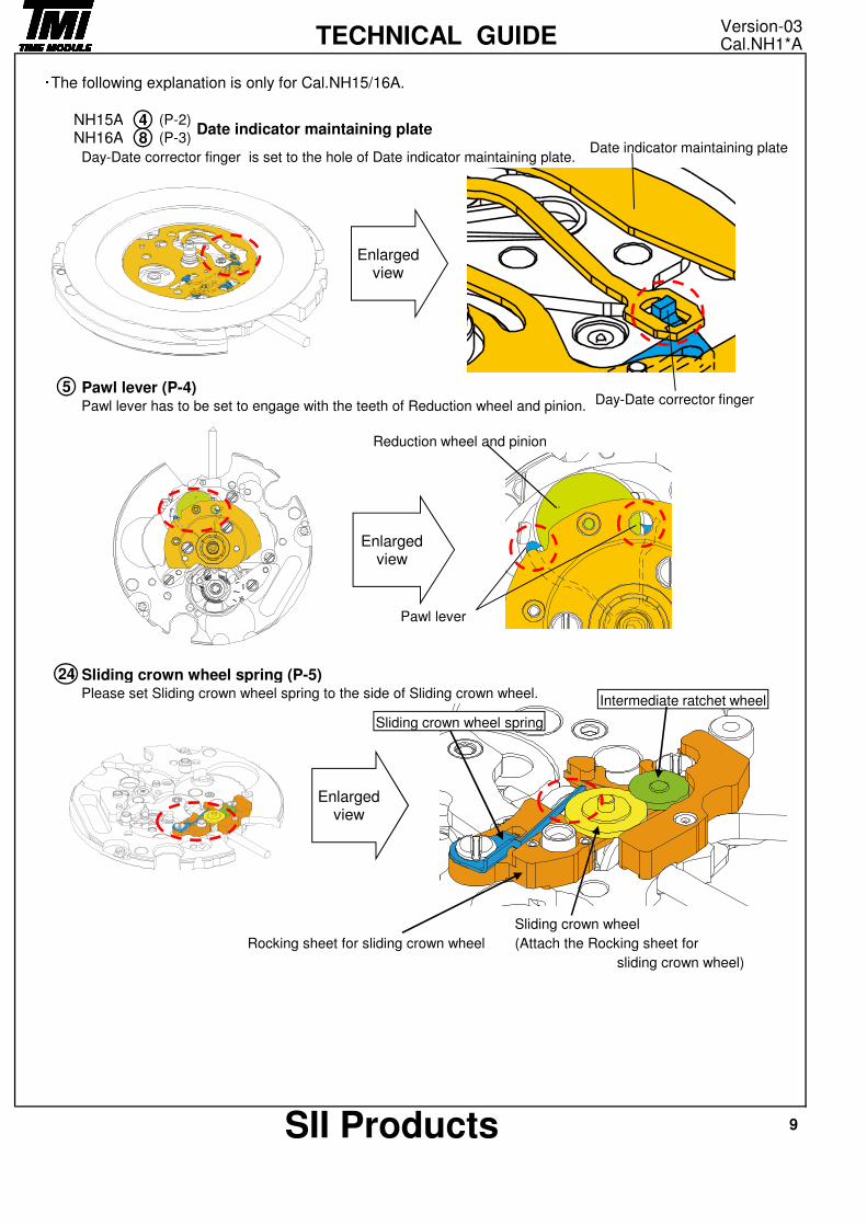
・The following explanation is only for Cal.NH15/16A.
Day-Date corrector finger is set to the hole of Date indicator maintaining plate.
Pawl lever (P-4)Pawl lever has to be set to engage with the teeth of Reduction wheel and pinion.
Sliding crown wheel spring (P-5)Please set Sliding crown wheel spring to the side of Sliding crown wheel.
Sliding crown wheel
Rocking sheet for sliding crown wheel (Attach the Rocking sheet for
sliding crown wheel)
9SII Products
4
5
24
8NH15ANH16A
Version-03Cal.NH1*ATECHNICAL GUIDE
Date indicator maintaining plate(P-2)
(P-3)
Enlarged view
Enlarged view
Date indicator maintaining plate
Day-Date corrector finger
Reduction wheel and pinion
Pawl lever
Enlarged view
Sliding crown wheel spring
Intermediate ratchet wheel
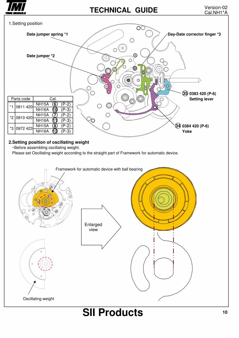
1.Setting position
Date jumper spring *1 Day-Date corrector finger *3
Date jumper *2
0383 420 (P-6)
Setting lever
0384 420 (P-6)
Yoke
2.Setting position of oscillating weight・Before assembling oscillating weight.
Please set Oscillating weight according to the straight part of Framework for automatic device.
Framework for automatic device with ball bearing
Oscillating weight
*3
*2 0810 420
0972 423
7
11
Parts code Cal.
*1 0811 4206
10
(P-2)
(P-3)
10SII Products
NH15A
NH16A
8
12
(P-2)
(P-3)
Version-02Cal.NH1*ATECHNICAL GUIDE
34
35
NH15A
NH16A
NH15A
NH16A
(P-2)
(P-3)
Enlarged view
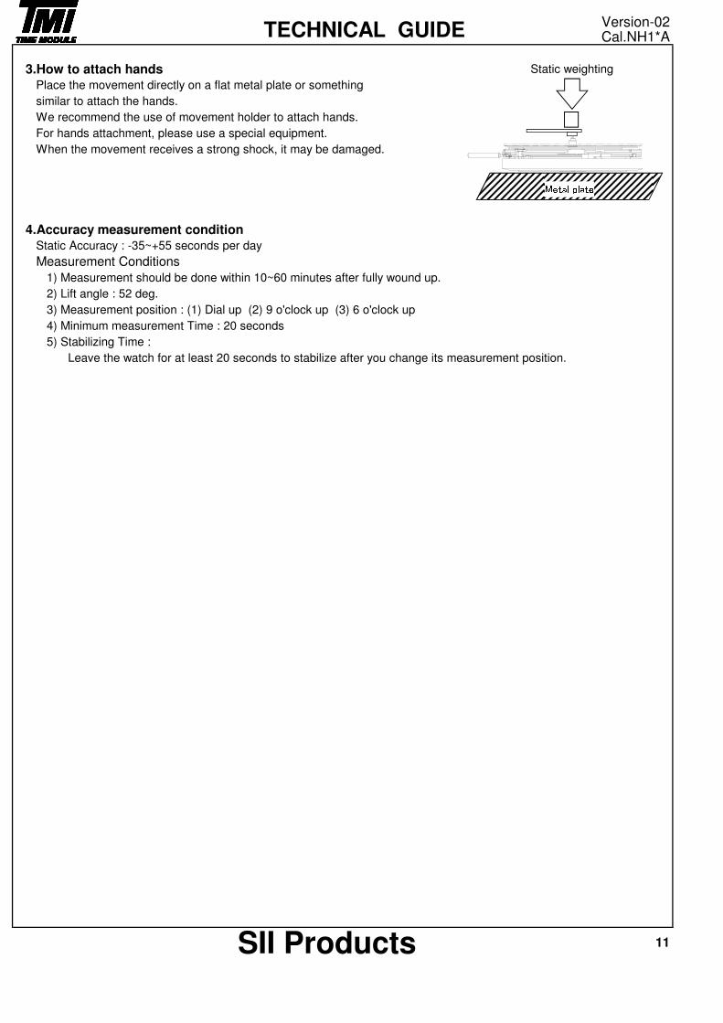
3.How to attach hands Static weighting
Place the movement directly on a flat metal plate or something
similar to attach the hands.
We recommend the use of movement holder to attach hands.
For hands attachment, please use a special equipment.
When the movement receives a strong shock, it may be damaged.
4.Accuracy measurement conditionStatic Accuracy : -35~+55 seconds per day
Measurement Conditions
1) Measurement should be done within 10~60 minutes after fully wound up.
2) Lift angle : 52 deg.
3) Measurement position : (1) Dial up (2) 9 o'clock up (3) 6 o'clock up
4) Minimum measurement Time : 20 seconds
5) Stabilizing Time :
Leave the watch for at least 20 seconds to stabilize after you change its measurement position.
11SII Products
Version-02Cal.NH1*ATECHNICAL GUIDE
Metal plate
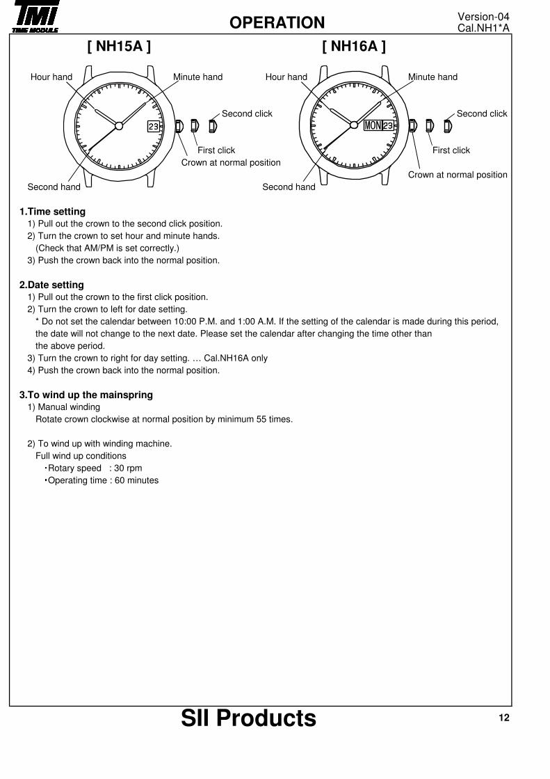
Hour hand Minute hand Hour hand Minute hand
Second click Second click
First click First click
Crown at normal position
Crown at normal position
Second hand Second hand
1.Time setting1) Pull out the crown to the second click position.
2) Turn the crown to set hour and minute hands.
(Check that AM/PM is set correctly.)
3) Push the crown back into the normal position.
2.Date setting1) Pull out the crown to the first click position.
2) Turn the crown to left for date setting.
* Do not set the calendar between 10:00 P.M. and 1:00 A.M. If the setting of the calendar is made during this period,
the date will not change to the next date. Please set the calendar after changing the time other than
the above period.
3) Turn the crown to right for day setting. … Cal.NH16A only
4) Push the crown back into the normal position.
3.To wind up the mainspring1) Manual winding
Rotate crown clockwise at normal position by minimum 55 times.
2) To wind up with winding machine.
Full wind up conditions・Rotary speed : 30 rpm・Operating time : 60 minutes
12SII Products
Version-04Cal.NH1*AOPERATION
[ NH15A ] [ NH16A ]