Embed Size (px)
Citation preview
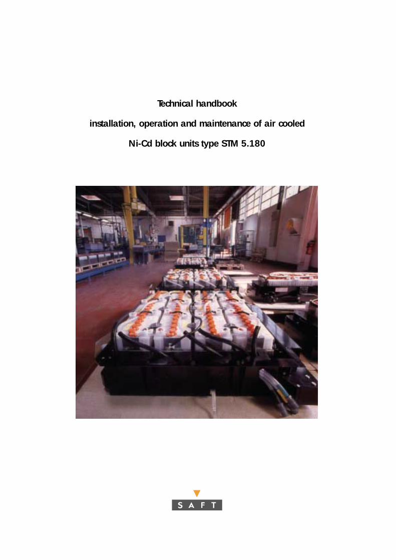
Technical handbook
installation, operation and maintenance of air cooled
Ni-Cd block units type STM 5.180
Introduction 4
Important recommendations 5
1. Characteristics of STM blocks 61.1. General description 6
1.1.1. Operation principle of vented Ni-Cd cells 61.1.2. Description of STM nickel-cadmium blocks 6
1.2. Mechanical characteristics 71.3. Electrical characteristics 71.4. Water filling system 8
1.4.1. General description 81.4.2. Working principle of the vent plug 9
2. Precautions and practices 102.1. Transport, storage 102.2. Water and electrolyte 10
2.2.1. Water quality 102.2.2. Harm caused in using sulfuric acid 10
2.3. Electrical shock and burns 112.4. Possible dangers through hydrogen 11
3. Installation 12 3.1. Assembly into batteries 123.2. Ventilation and cooling 123.3. Assembly of water filling system 13
3.3.1. Precautions and general rules 133.3.2. General instructions for assembly 133.3.3. Fitting the elbow on the plug 13
Contents
4. Placing blocks into service 154.1. Preparation before use 154.2. Commissioning cycle 15
5. Operation 165.1. Operating temperature 165.2. Charging in service 16
5.2.1. Constant current charge 165.2.2. Recommanded charging method 17
5.3. Discharge 185.3.1. Discharge currents 185.3.2. End voltages in discharge 18
6. Maintenance 196.1. Periodic maintenance 196.2. Topping up operation 19
7. Equipment repair and overhaul 207.1. Electrolyte specific gravity 207.2. Reconditioning 207.3. Replacing vent plug 21
Appendix 1 22Appendix 2 23Appendix 3 24Accessories of the water filling system 25
Edition April 2001
Introduction
4
The information provided in thismanual is intended to help operatorand maintenance personnel toobtain the best performance andmaximum life from their Saft Ni-CdSTM block batteries.
It describes the main characteristicsand operating principles of theblocks and provides generalinstructions to users and technicianson how to operate, maintain, repair, overhaul and otherwise care for them.
The instructions are of generalvalidity for batteries in ElectricVehicles. Nevertheless, every type of car will have a specific batteryassembly and particular operatingprinciples, especially with regards to the various mechanical, electrical,thermal and other interfaces.Specific instructions depending onthe type of car can therefore beadded to this document.
If you wish to use the battery outsidethe limits stated herein, pleaseconsult us first.
Important recommendations
5
! Install the battery such as toensure good ventilation.
! Never allow a flame or fire tocome near the battery.
! The electrolyte is harmful toskin and to eyes in particular.In the event of contact with skin or eyes, wash immediatelywith running water and/or a 10 % solution of boric acid.
! Wear gloves and goggles tomanipulate the electrolyte.
! Never use sulfuric acid oracidified water to top-upelectrolyte, as acid, even intraces, destroys the battery.
! When batteries are operated in closed premises, room airshould be renewed inaccordance with applicablesafety codes and regulations.
1. Characteristics of STM blocks
6
1.1. General description
1.1.1. Operation principle ofvented Ni-Cd cells
Batteries are electrochemicaldevices used to supply energy toelectrical and electronic products.Chemical energy stored in abattery is converted into electriccurrent when the battery isdischarged. This electric current is produced directly by chemicalreactions that occur within the battery.
The nickel-cadmium cell is anelectrochemical system in whichthe electrodes containing theactive materials undergo changesin oxido-reduction state withoutany change in physical state. The active materials are highlyinsoluble in alkaline electrolyte.They remain as solids and do not dissolve while undergoingchanges in oxido-reduction state.Because of this, the electrodesare long-lived, since no chemicalmechanism exists that wouldcause the loss of active materials.
During the cell charging anddischarging operations, hydroxylions are transferred from thepositive to the negative plates via the electrolyte. The alkalinesolution, KOH, (electrolyte) actsonly as the transfer medium.
It does not participate in theelectrochemical reaction. Its rolein the operations being ratherpassive, the electrolyte in anickel-cadmium cell is neveraffected by the state of charge of the cell itself.
During overcharge, the watercontained in the electrolyte isdecomposed into O2 and H2. A part of these gasses leaves thecells through their vents and thehydraulic system. Consequently,the electrolyte reserve is reducedand topping up of the cells withwater becomes necessary after a certain number of cycles.
1.1.2. Description of STM nickel-cadmium blocks
STM blocks consist of 5 nickel-cadmium cells of 1.2 V nominalvoltage each. Assembled into acompact unit of 5 cells, the STMmonoblock has a nominal voltageof 6 V.
If delivered in single block units(not pre-assembled by Saft intocrates or boxes), the blocks aresupplied with end plates.
Do not remove those of the STM 5.180 blocks, as they areintegrated into the block container.
The blocks will be assembled intoa battery by serial (and eventuallyalso parallel) interconnection, inorder to achieve the specifiedbattery capacity and voltage.When mounted into a vehicle, the blocks must be installed withsufficient space for ventilation(refer to chapter 3).
! Electrodes
The STM blocks are constituted of sintered positive electrodesand plastic bonded negativeelectrodes. The sinter positive is obtained by chemicalimpregnation of nickel hydroxide
into a porous nickel structure,which was obtained beforehandby sintering nickel powder onto a thin, perforated and nickel-plated steel strip. Positive andnegative electrodes are organisedin alternates and separated by a multi-layer separator.
! Electrolyte
The alkaline electrolyte in a nickel-cadmium battery is a solution of potassium hydroxide(KOH), lithium hydroxide (LiOH),sodium hydroxide (NaOH) anddistilled or demineralized water.During the electrochemicalreaction, its specific gravityremains essentially constant andcan thus not be used as anindicator of state of charge. The specific gravity, however,varies due to the normal waterconsumption during overcharges.The gravity is low when the cellsare topped up to their maximum,it is high when the electrolytereserve is all consumed. The electrolyte used in STM blockshas a specific gravity of 1.21.
! Block container
The block container is made oftranslucent polypropylene. The block cover, also inpolypropylene, is thermoweldedto the container after introductionand interconnection of the plategroups ("through-the-wall"interconnection principle).
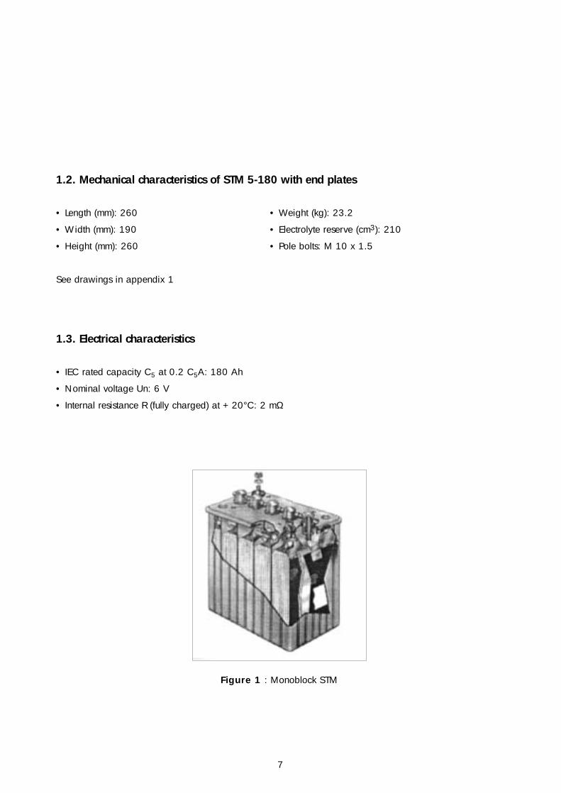
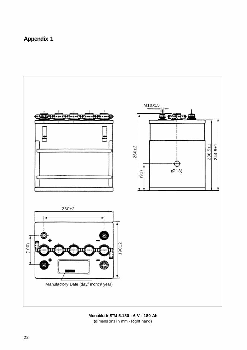
1.2. Mechanical characteristics of STM 5-180 with end plates
• Length (mm): 260 • Weight (kg): 23.2
• Width (mm): 190 • Electrolyte reserve (cm3): 210
• Height (mm): 260 • Pole bolts: M 10 x 1.5
See drawings in appendix 1
1.3. Electrical characteristics
• IEC rated capacity C5 at 0.2 C5A: 180 Ah
• Nominal voltage Un: 6 V
• Internal resistance R (fully charged) at + 20°C: 2 mΩ
Figure 1 : Monoblock STM
7
8
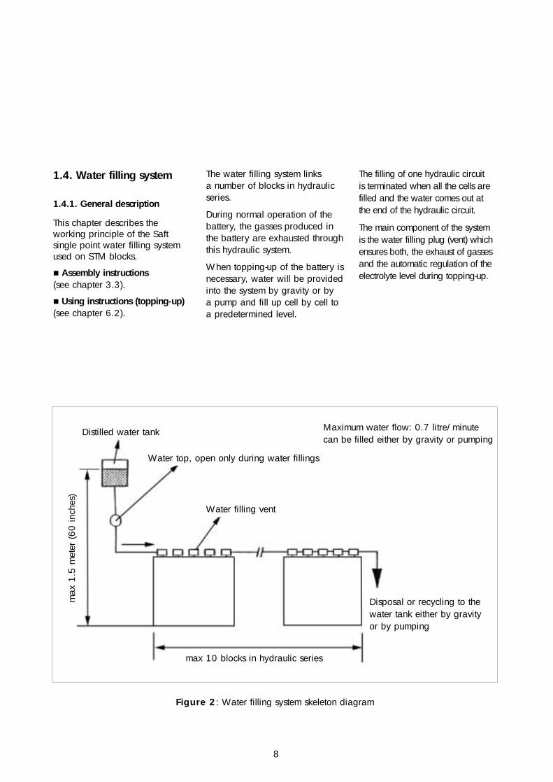
1.4. Water filling system
1.4.1. General description
This chapter describes theworking principle of the Saftsingle point water filling systemused on STM blocks.
! Assembly instructions (see chapter 3.3).
! Using instructions (topping-up) (see chapter 6.2).
The water filling system links a number of blocks in hydraulicseries.
During normal operation of thebattery, the gasses produced inthe battery are exhausted throughthis hydraulic system.
When topping-up of the battery isnecessary, water will be providedinto the system by gravity or by a pump and fill up cell by cell toa predetermined level.
The filling of one hydraulic circuitis terminated when all the cells arefilled and the water comes out atthe end of the hydraulic circuit.
The main component of the systemis the water filling plug (vent) whichensures both, the exhaust of gassesand the automatic regulation of theelectrolyte level during topping-up.
Maximum water flow: 0.7 litre/minute can be filled either by gravity or pumping
Disposal or recycling to thewater tank either by gravityor by pumping
max 10 blocks in hydraulic series
Figure 2: Water filling system skeleton diagram
max
1.5
met
er (6
0 in
ches
)
Water filling vent
Distilled water tank
Water top, open only during water fillings
9
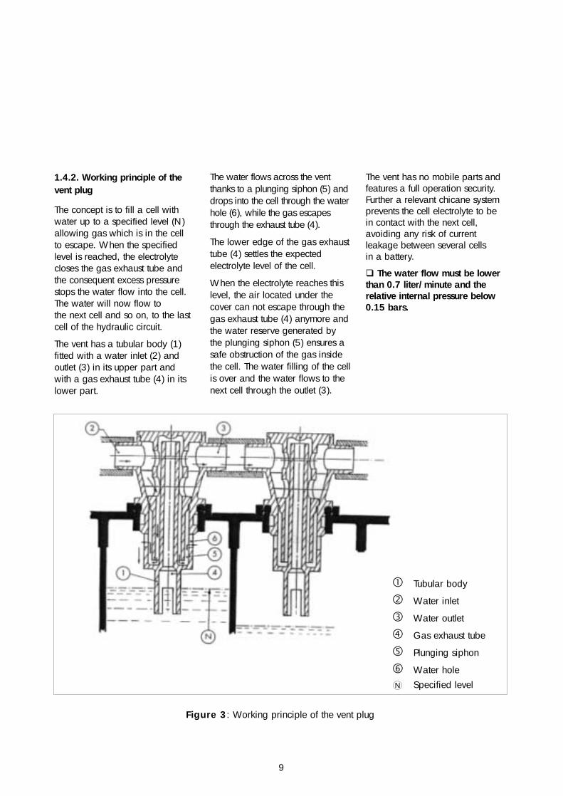
1.4.2. Working principle of thevent plug
The concept is to fill a cell withwater up to a specified level (N)allowing gas which is in the cellto escape. When the specifiedlevel is reached, the electrolytecloses the gas exhaust tube andthe consequent excess pressurestops the water flow into the cell.The water will now flow to the next cell and so on, to the lastcell of the hydraulic circuit.
The vent has a tubular body (1)fitted with a water inlet (2) andoutlet (3) in its upper part andwith a gas exhaust tube (4) in itslower part.
The water flows across the ventthanks to a plunging siphon (5) anddrops into the cell through the waterhole (6), while the gas escapesthrough the exhaust tube (4).
The lower edge of the gas exhausttube (4) settles the expectedelectrolyte level of the cell.
When the electrolyte reaches thislevel, the air located under thecover can not escape through thegas exhaust tube (4) anymore andthe water reserve generated bythe plunging siphon (5) ensures asafe obstruction of the gas insidethe cell. The water filling of the cellis over and the water flows to thenext cell through the outlet (3).
The vent has no mobile parts andfeatures a full operation security.Further a relevant chicane systemprevents the cell electrolyte to bein contact with the next cell,avoiding any risk of currentleakage between several cells in a battery.
" The water flow must be lowerthan 0.7 liter/minute and therelative internal pressure below0.15 bars.
Figure 3: Working principle of the vent plug
# Tubular body
$ Water inlet
% Water outlet
& Gas exhaust tube
' Plunging siphon
( Water holeN Specified level
2. Precautions and practices
10
2.1. Transport and storage
STM batteries are delivered filledwith electrolyte and discharged(unless otherwise specified). It isnormal that the electrolyte level isnot visible after a long storage andtransport period. The electrolyte will become visibleduring charge (refer to chapter 4).
According to customer specification,STM blocks can be deliveredcompletely assembled into batteries,or partly assembled or as a kit ofblocks and accessories. In the latter two cases, in order toavoid any spilling of electrolyteduring transport, the blocks arefitted with transport plugs inserted inthe vent plugs.
If not placed immediately intoservice, store batteries in a closed,dry area in their original packagingor otherwise. In the latter case,make sure filler holes are correctlyclosed, with transport plugs.
" Never drain the cell's electrolyte
The battery units can be stored inany state of charge. The batterycan be stored this way for severalyears and without any furtherspecial precaution.
After a storage period of morethan one year, it is necessary tocarry out a reconditioning cyclebefore use.
2.2. Water and electrolyte
The water and electrolyte used inSaft Ni-Cd batteries must bechemically pure.
Under normal operatingconditions, STM batteries do notrequire any charge of, orcompletement to, their originalelectrolyte (KOH).
Cells do lose water only when thebattery is being overcharged.Cell electrolyte level is returned to maximum level only by additionof water (see chapter 6.2.).
" If cells have lost theirelectrolyte by accident(mishandling, drop, overflow...)it may be necessary to replenishthe electrolyte after check ofelectrolyte density.
This can only be done by Saftauthorized personnel. Please contact us.
" Never measure the electrolytespecific gravity after a topping-upoperation.The electrolyte above the platestack will be diluted and you willthus measure wrong values.
Electrolyte is homogeneous againafter some charge/discharge cycles.
2.2.1. Water quality
lt is absolutely necessary to usechemically pure water (eitherdistilled or demineralized) fortopping-up, as ordinary water,even drinking water, containsimpurities which will pollute theelectrolyte in the long run andadversely affect cell operation.Store water in plastic containers.Keep closed.
2.2.2. Harm caused in usingsulfuric acid
Sulfuric acid (as it is used in lead-acid batteries) damages alkalinebatteries. Do not put sulfuric acidin a nickel-cadmium battery.
Also prohibit the use of topping-upwater recommended for lead-acidbatteries since it may containsulfuric acid.
In case of doubt, make sure withlitmus paper (or equivalent) thatthe water does not exhibit anyacid reaction.
" Never check or top up thebatteries with instruments usedfor lead-acid batteries.
11
2.3. Electrical shock andburns
Multicell systems attain highvoltages. Therefore extremecaution must be exercised duringthe installation and maintenanceof a battery system to preventserious electrical burns or shock.
" Cut off the AC and DC circuitsbefore working on batteries.
Assure that personnel understandthe risk of working with highvoltage batteries and are equippedwith insulated tools and otheradequate protection equipment.
2.4. Possible dangersthrough hydrogen
The STM blocks are connected inhydraulic series. The hydraulicsystem exhausts H2 and O2gasses, which are mainlyproduced during overcharge.
" Be aware that the hydraulicsystem can contain highly explosivegasses at any moment.
When dealing with the battery,special attention must thereforebe drawn to the hydraulic systemin order to avoid any leakage. If a leakage is observed, it mustbe repaired immediately.
Furthermore, general safety rulesmust be observed very strictly:ensure good ventilation, avoidany flame or heat source to comenear to the battery.
3. Installation
12
A good mechanical installation,ventilation and thermalmanagement of the batteries arecrucial to ensure a long life, bestperformances and user safety.
This manual can only providegeneral rules of how to assembleSTM blocks into batteries.
The final installation will bespecific to every vehicle.
Any battery installation must beagreed by Saft in order to engageour product responsibility.
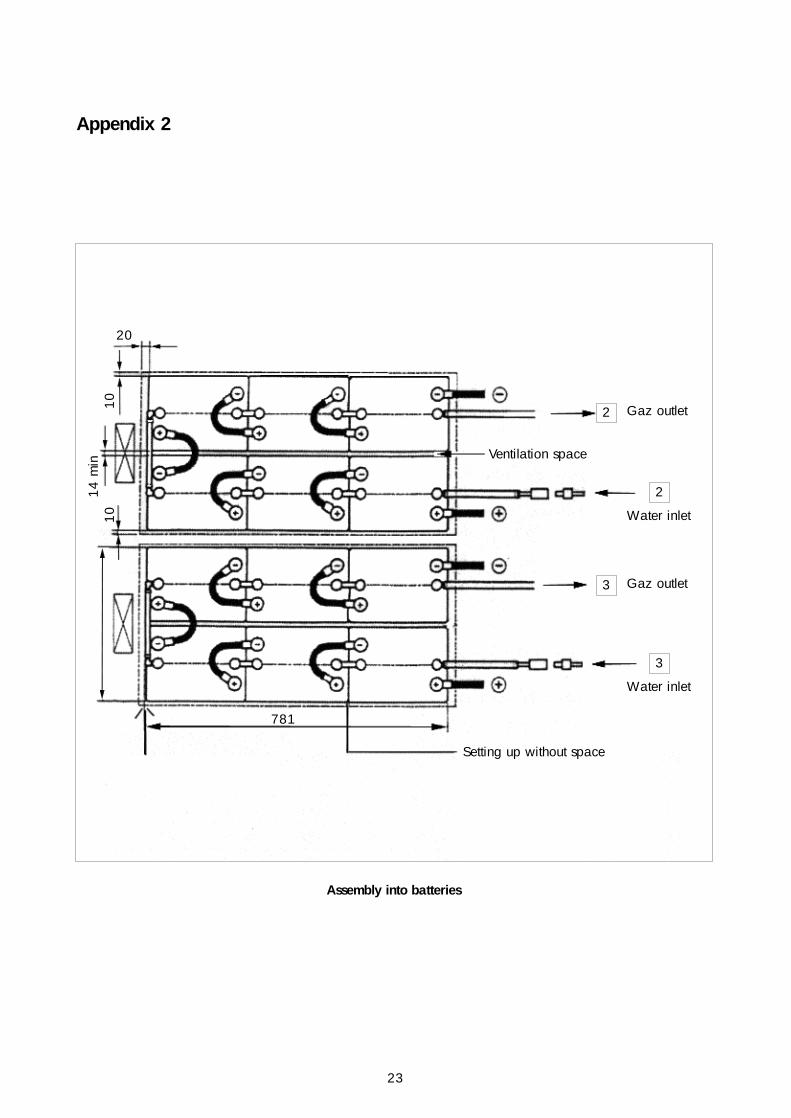
3.1. Assembly into batteries
The electrical connection in series of blocks will be made accordingto the space available and tominimize the length of the cables.
The connection of the hydraulicsystem to each of the blocks willfollow a path parallel to theelectrical circuit so that there is nopotential difference between the two ends of a connecting pipe.
The maximum number of blocksconnected in hydraulic series islimited to ten on a single circuit. For larger battery units, severaltotally independent circuits will beprovided (for details see 3.3.).
The blocks must be mechanicallysupported and must not be able tomove in any horizontal or verticaldirection.
Only the small sides of the blocksmust be braced in case of connectionof rows of several blocks.
In practice, the blocks will be set upin rows in the axis of the smallsides, without any gap.
A supporting structure at the twoends of the row (either bracing orbattery box) must withstand aexpanding force from the battery ofapproximately 150 dN per row.
On their longer side, the blocksmust be set up with a gap.
A ventilation space of 14 to 20 mmmust be foreseen between the rows(refer section 3.2.).
See example of battery assembly inappendix 2.
3.2. Ventilation and cooling
During operation, STM batteriesgenerate heat. When used indaily cycling, a steady heataccumulation must be avoided.The battery therefore needsventilation (respectively a coolingsystem) in order to withdraw theaccumulated heat in the mostefficient way.
Therefore, the blocks must be setup with some space in order tomake heat exchange possible.The most efficient heat exchangecan be done on the larger side of the blocks.
In practice, 14 to 20 mm spaceare to be foreseen between therows of blocks and will serve asventilation/cooling channels.
In addition to that, ventilationspace above and/or underneaththe blocks can improve the heatdissipation. In case of aircooling, the cold air is suckedthrough the battery by fans,either in vertical or horizontaldirection. In any case, thecooling system will be designedin order to ensure the mosthomogenous temperature of theblocks in one battery.
Furthermore, it is recommended tocontrol the battery temperature bysensors or thermostats, which canbe supplied by Saft on request.
The optimized solutions for acooling system must be designedfor every battery, depending onthe type of car, its use, the typeof battery etc.
13
3.3. Assembly of waterfilling system
3.3.1. Precautions and generalrules
The water filling system links anumber of blocks in hydraulicseries. The installation of such asystem must therefore be carriedout very carefully in order toensure good and safe operation,and to avoid any kind of gas orelectrolyte leakages.
• It is very important to ensurethat the hydraulic system issealed, i.e. that no gas and/orwater leakages occur.Connecting of pipes, plugs andelbows must be carried outcarefully. Whenever a leakage is observed (maybe after sometime of operation), this must berepaired immediately.
• The risk of leaking currentsthrough the hydraulic system (whichis carrying gases and water !) mustbe reduced as much as possible.
Therefore we must make sure that:
- the hydraulic connection alwaysfollows the electrical one, inorder not to create a potentialdifference more than the voltageof one cell between twohydraulically connected cells.
- not more than 50 cells (i.e. 10blocks) are connected in onehydraulic series. This limits thevoltage on one hydraulic circuit to 60 V nominal.
As a general rule, Saft blocks, ifforeseen with a centralized water
filling system, are equipped withthe water filling plugs.
In order to assemble the battery,we add the necessary acces-sories, such as pipes, elbows,glue, flame arresting devices,water plugs. Please see detaileddescription and part numbers inappendix 3.
3.3.2. General instructions forassembly
! Levels
The whole system should be atabout the same level. However, if different levels exist, start thehydraulic circuit at the highestpoint, so that the water canalways flow downwards.
! Pipes
For distances less than 200 mm(between two plugs for example),use the flexible, clear pipe diameter9x12 mm, part number 444 083.
For distances greater than 200 mm(towards the water reservoir, forexample) or when forming loops,use the reinforced flexible pipediameter 10x16 mm, part number208 859. For angles of 180°, it ispreferable to use the polypropyleneelbow (part number 444 103).
Avoid all nipping of the flexiblepipes when a loop is formed.
Avoid to form vertical loops inwhich water would stay after thefilling operation.
! Inlets and outlets
During normal operation (nottopping-up), the hydraulic system
must be closed on one side (inlet),so that any gas will escape on the outlet.
• For the water inlet, use selfclosing connecting plugs, Saftpart number 208 854 (socket or"female") and 208 855 (plug or"male").
When disconnecting these plugs,both parts will automatically beclosed, i.e.
- the inlet to the hydraulic circuiton the battery side is closed,
- the pipe to the water reservoir isclosed, and no more water will flow.
• For the water/gas outlet, do notuse self closing plugs.
You may use free-pass plugs, Saft part number 208 751(coupling) and 208 752 (nipple).
3.3.3. Fitting the elbow on the plug
It is forbidden to force or push theelbow all the way on to the plugbefore the application of glue to theelbow (the action of which softensthe elbow).
Otherwise, the elbow will break dueto the conic shape of the plug nozzle.
To glue an elbow to the plug, use specific cement ("glue") Saftpart number 208 793.
Make sure that the deadline foruse (printed on the tube) has notoccurred yet (refer figure 5).
Avoid any traces of electrolyte on the plug nozzle or the elbowbefore glueing.
14
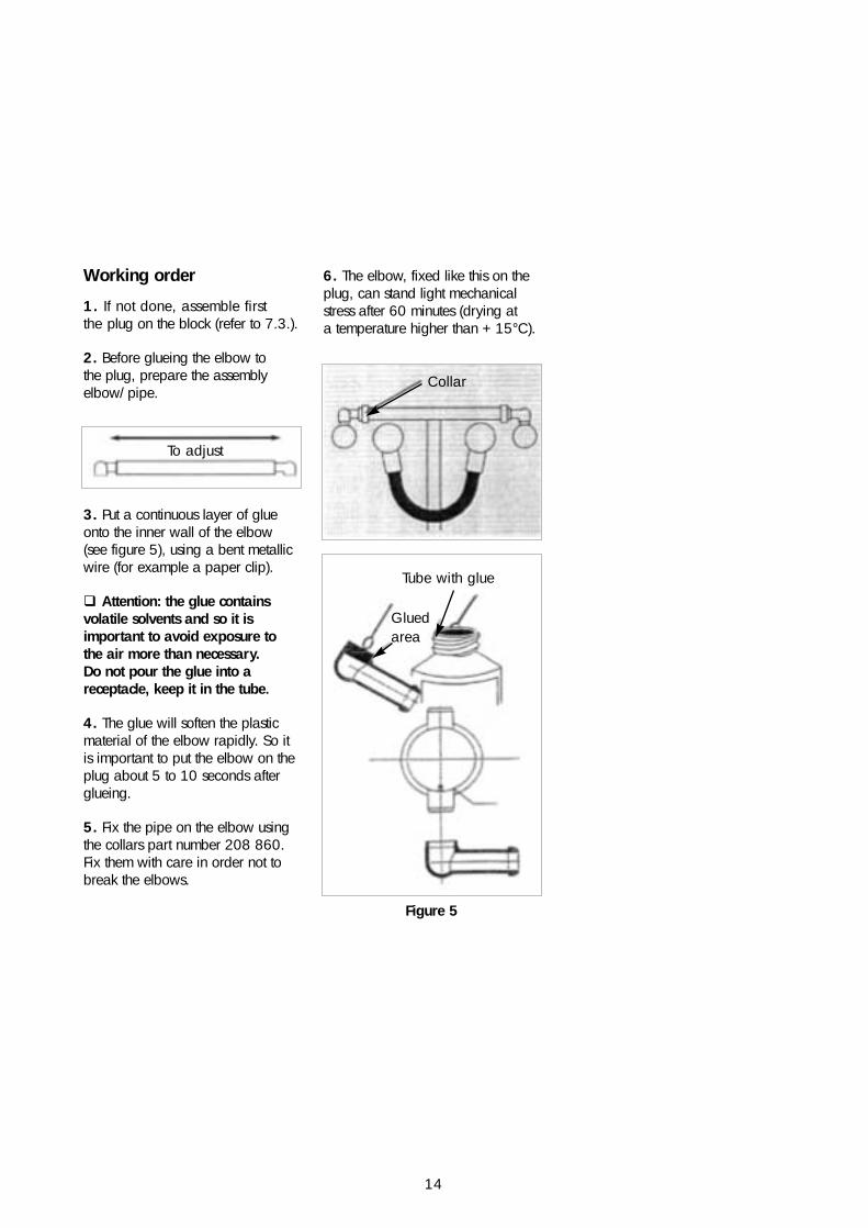
Working order
1. If not done, assemble first the plug on the block (refer to 7.3.).
2. Before glueing the elbow to the plug, prepare the assemblyelbow/pipe.
3. Put a continuous layer of glueonto the inner wall of the elbow(see figure 5), using a bent metallicwire (for example a paper clip).
" Attention: the glue containsvolatile solvents and so it isimportant to avoid exposure to the air more than necessary. Do not pour the glue into areceptacle, keep it in the tube.
4. The glue will soften the plasticmaterial of the elbow rapidly. So itis important to put the elbow on theplug about 5 to 10 seconds afterglueing.
5. Fix the pipe on the elbow usingthe collars part number 208 860.Fix them with care in order not tobreak the elbows.
To adjust
Tube with glue
Glued area
Figure 5
Collar
6. The elbow, fixed like this on theplug, can stand light mechanicalstress after 60 minutes (drying at a temperature higher than + 15°C).
4. Placing blocks into service
15
STM blocks are delivered filled and uncharged. On receptionand/or after a storage period, a commissioning cycle is required.
Do not top up with water orelectrolyte prior to the first charge,even if the electrolyte level isunderneath the minimum level. In fact, after longer storage periods,the electrolyte can be totallyabsorbed by the electrodes.
If delivered in individual units, the blocks are provided withshipping plugs on the vents in orderto prevent loose of electrolyte.
4.1. Preparation before use
a) Remove shipping plugs fromcells, if any.
b) Ensure correct and tight hydraulicinterconnection.
c) Verify that electrical inter-connection of the blocks and theconnection of the battery to the loadare correct.
d) Check tightness of terminalconnecting nuts.
Torque applied should be asfollows:
12 ± 2 N.m
4.2. Commissioning cycle
a) Constant current charge at 18 A(0.1 C5) during 14 hours withoutvoltage limit.
b) Rest period of 1 hour.
c) Topping up with water fillingsystem (see 6.2.).
5. Operation
16
! Temperature during charging
For optimum battery performanceand life time it is preferable tobegin charging at an internalbattery temperature of below35°C. This means in practice thatafter discharge, if time issufficient, the battery is cooleddown below 35°C before startingthe charging operation. Thistemperature can be exceededoccasionally. In that case thecharging process will be done atlower charging efficiency, andthe battery will not be fullycharged. When charging againat normal temperature, thebattery capacity will be restoredby a full charge.
5.1. Operating temperature
Due to the electrochemicalreaction, all Ni-Cd batteriesgenerate heat (calories) to acertain extend during the chargeand discharge operation. As STMmonoblock batteries are batteriesof high energy density, and asthey are used in regular cycling,particular attention must be paidto the thermal behaviour of thebattery. In daily cycling applications withcurrents > 0.1 C5, a coolingsystem and temperature control of the battery are recommended,in order to keep the batterytemperature within the limitsmentioned hereunder. The temperature measured in a central cell must be less than45°C in continuous state. Thistemperature may be exceededexceptionally (for example whendischarged at high rate). The maximum permissibletemperature is 60°C.
5.2. Charging in service
5.2.1. Constant current charge
! Normal charge
In cycling applications, STMbatteries are preferably chargedin a constant current mode withcurrent rates between 27 A (0.15 C5) and 36 A (0.2 C5).
! Fast charge
Possibility of recharging up to 80 percent of the capacity at a charging current of 270 A (1.5 C5) with a voltage cut-off of 8 V/block.
17
5.2.2. Recommended chargingmethod
Valid for a temperature range from0°C (32°F) to + 35°C (95°F).
The charging method describedbelow is supposed to be ofgeneral validity for ElectricVehicles equipped with STMbatteries. However, specificcharging modes, depending oncustomer specific usingconditions, climatic conditions,etc. can be worked out. Pleaseconsult Saft.
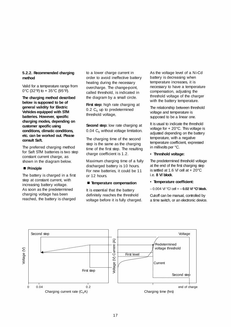
The preferred charging methodfor Saft STM batteries is two stepconstant current charge, asshown in the diagram below.
! Principle
The battery is charged in a firststep at constant current, withincreasing battery voltage. As soon as the predeterminedcharging voltage has beenreached, the battery is charged
to a lower charge current inorder to avoid ineffective batteryheating during the necessaryovercharge. The change-point,called threshold, is indicated inthe diagram by a small circle.
First step: high rate charging at0.2 C5 up to predeterminedthreshold voltage,
Second step: low rate charging at0.04 C5 without voltage limitation.
The charging time of the secondstep is the same as the chargingtime of the first step. The resultingcharge coefficient is 1.2.
Maximum charging time of a fullydischarged battery is 10 hours.For new batteries, it could be 11or 12 hours.
! Temperature compensation
It is essential that the batterydefinitely reaches the thresholdvoltage before it is fully charged.
As the voltage level of a Ni-Cdbattery is decreasing whentemperature increases, it isnecessary to have a temperaturecompensation, adjusting thethreshold voltage of the chargerwith the battery temperature.
The relationship between thresholdvoltage and temperature issupposed to be a linear one.
It is usual to indicate the thresholdvoltage for + 20°C. This voltage isadjusted depending on the batterytemperature, with a negativetemperature coefficient, expressedin millivolts per °C.
• Threshold voltage:
The predetermined threshold voltageat the end of the first charging stepis settled at 1.6 V/cell at + 20°Ci.e. 8 V/block.
• Temperature coefficient:
– 0.004 V/°C/cell = – 0.02 V/°C/block.
Cut-off can be manual, controlled bya time switch, or an electronic device.
0 0.04 0.2 end of chargeCharging current rate (C5A)
Second step
Volta
ge (V
)
Volta
ge (V
) Cur
rent
(A)
Voltage
Predeterminedvoltage threshold
Current
Second step
First level
First step
Charging time (hrs)
18
Recommended chargingmethod for STM 5.180 block• First step:I const. 0.2 C5: 36 AUthresth: 8 V/blockTime t1: until battery reaches Uthresh
• Second step:I const. 0.04 C5: 7.2 AUthresth: openTime t2 = t1
• Temperature coefficient:– 0.02 V/°C/block
• Overcharge coefficient: 1.20
5.3. Discharge
5.3.1. Discharge currents
The maximum continuous dischargecurrent is 360 A (2 C5). At thiscurrent, the battery units must beventilated in order to limit heating(electrolyte temperature < 60°C).
Peak discharges of short duration,less than or equal to 15 sec, up to a current of 900 A (5 C5A)are possible.
5.3.2. End voltages in discharge
The voltage level during dischargedepends on the current drawn onthe battery, and the temperature.
The rated capacity of STM blocksare determined at + 20°C and endvoltages of 5 V.
In practice, STM blocks can bedischarged down to 0 V.Even occasional reversal (U < 0 V)will not harm the blocks.
However, it is recommended not toreverse the blocks regularly, and itshould be endeavored to comply withthe cut-off voltages listed below:
Current 0.2 C5
Capacity measured at 5.0 V/blockCut-off voltage: 5.0 V/block
Current 1 C5
Capacity measured at 4.5 V/blockCut-off voltage: 4.5 V/block
Current 2 C5
Capacity measured at 4 V/blockCut-off voltage: 4 V/block
Examples of charge voltage at different temperatures:
! Charging of one STM block at +35°C (95°F):Threshold voltage at +20°C (68°F) ........................................8 VTemperature when charging ....................................+35°C (95°F) Temperature difference from +20°C ....................................+ 15°CThreshold voltage correction .........+15°C x (–0.02) V/°C = –0.3 VThreshold voltage for charge at 0°C ..................8 V – 0.3 V = 7.7 V
! Charging voltage of two STM block at 0°C (32°F):Threshold voltage at +20°C (68°F) ........................2 x 8 V = 16 VTemperature when charging..........................................0°C (32°F)Temperature difference from +20°C ....................................–20°CThreshold voltage correction ......–20°C x (–0.02 x 2)V/°C = 0.8 VCharging voltage for charge at 0°C ............16 V +0.8 V = 16.8 V
Charging time for a 50% discharged batttery:First step charging time ..................................................2.5 hoursSecond step charging time ............................................2.5 hoursTotal charging time ..............................................about 5.0 hours
6. Maintenance
19
6.1. Periodic maintenance
When the charging equipment iscarefully adjusted and functionscorrectly, STM batteries require,under normal operating conditions,no regular maintenance aparttopping-up (refer to 6.2.).
They need to be given briefgeneral inspection, which is usuallypossible to carry out at the sametime as the general inspection ofthe vehicle. During this inspection,it is sufficient:
• to check tightness of connectors
• to check that the hydraulicsystem is sealed
• if necessary, to clean the batterywith soapy water (do not use anydetergents).
Checking of electrolyte density andreconditioning charges are notrequired systematically, but onlywhen, by accident, this becomesnecessary (refer to 7.1. and 7.2.).
6.2. Topping-up operation
! Measuring the electrolyte level
Topping-up with distilled ordemineralized water (for waterquality refer to 2.2.) is necessary,because Ni-Cd batteries loosewater in form of H2 and O2gasses during overcharge.
The electrolyte level can be seenon the blocks from outside throughthe plastic container. The onlyreliable moment to measure theelectrolyte level is at the end of
charge, respectively some minutesafter the end of charge (when theelectrolyte is at its highest level).
Topping-up becomes necessary,when, at the end of charge, theelectrolyte level is at the MIN-markor below.
In practice, topping-up is doneafter a number of overchargedamperehours, or, otherwise, after a number of kilometers driven, or anumber of cycles, or a number ofAh discharged ; in fact, this ismainly determined by experience.
! Frequency of topping-up
Approximately once every 15 fullcycles, or after 3000 cumulateddischarged amperehours, ideallyevery 600 cumulated overchargedamperehours.
! Topping-up operation
" The topping-up operation is carried out one hour (± 15 min)after the end of charge.
If it is carried out earlier, residualgasses of the charging processmay disturb the operation. If it is carried out later than this,the electrolyte level will fall downand the operator risks to overfillthe blocks (overflow duringfollowing charge).
Water is entering the hydraulicsystem by gravity (water reservoir)or by a pump, according to theprinciples described in chapter 1.4.
The water inlet flow rate must beless than or equal to 0.7 liters perminute, and the relative pressuremust be below 0.15 bars.
The water will fill up the battery cellby cell. The end of topping-up ofeach hydraulic circuit is someseconds after continuous wateroverflow at the system outlet (inletthen closed manually or by relays).
7. Equipment repair and overhaul
20
7.1 Electrolyte specific gravity
As described in chapter 2.2.,electrolyte specific gravity must only be checked, and electrolyteeventually reconcentrated if the cellshave lost electrolyte by accident(overflow), and only if theperformances of the battery (afterreconditioning) are decreasedbecause of this phenomenon.
In order to measure the electrolytespecific gravity, it is necessary toremove the filling plugs from theblocks. It is important to renew alldisassembled connecting pipes and elbows when reassembling the plugs (refer to 7.3.).
Electrolyte specific gravity can bemeasured earliest 2 full cycles afterthe last topping-up operation.
Otherwise, the electrolyte abovethe plate stack will be diluted andyou will measure wrong values.
The nominal specific gravity ofelectrolyte used in STM blocks ata temperature of + 20°C is:1.21.The specific gravity practicallydoes not vary with the state ofcharge. The specific gravityvaries with the temperature. The specific gravity variesbetween two topping upoperations. Therefore, the lowestacceptable value for specificgravity, when electrolyte level is at"Max" is 1.17. If the specificgravity should be too low, areconcentration of the electrolytebecomes necessary. This must bedone by Saft authorizedpersonnel. Please contact us.
7.2. Reconditioning
Reconditioning shall beperformed when the batterycapacity is too low, or when the battery is disbalanced.
Reconditioning shall be done as follows:
a) Residual capacity discharge ofthe battery.
All the blocks of one batteryshould be underneath 5 V.
The discharge shall be done at acurrent of approximately 0.2 C5 A,36 A.
b) Constant current charge at thefollowing values:
18 A during 14 hours or 36 Aduring 7 hours with no voltagelimit.
c) Topping-up with water fillingsystem (refer to 6.2.).
d) If necessary, this operation canbe repeated.
21
7.3. Replacing vent plug New blocks are delivered withtheir plugs already fitted.Replacement of vent plugs maybecome necessary afteraccidental damage, leakages orfor other exceptional reasons.
When refitting a vent plug on a block, do always use newconnecting pipes and elbows.
Already used components mayhave traces of electrolyte, whichwill endeavour the air andelectrolyte tightness of thehydraulic system.
! Fitting a plug on a cell
Before fitting the plug on a block,put a trace of vaseline oil on theO-ring to avoid elastic stress onthe O-ring due to adhesion of the contacting surfaces. This willavoid a backward-rotation of theplug, which can mechanicallystress the connecting pipesbetween two plugs.
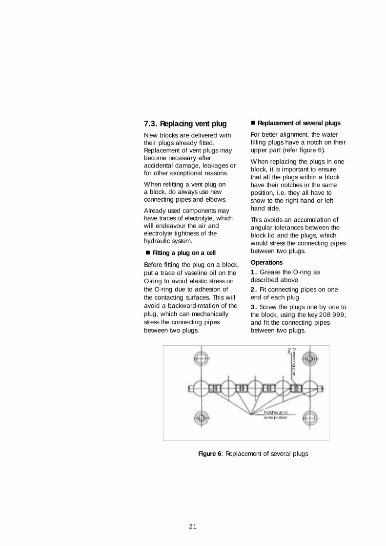
! Replacement of several plugs
For better alignment, the waterfilling plugs have a notch on theirupper part (refer figure 6).
When replacing the plugs in oneblock, it is important to ensurethat all the plugs within a blockhave their notches in the sameposition, i.e. they all have toshow to the right hand or lefthand side.
This avoids an accumulation ofangular tolerances between theblock lid and the plugs, whichwould stress the connecting pipesbetween two plugs.
Operations 1. Grease the O-ring asdescribed above 2. Fit connecting pipes on oneend of each plug 3. Screw the plugs one by one tothe block, using the key 208 999,and fit the connecting pipesbetween two plugs.
Notches all insame position
Figure 6: Replacement of several plugs
Connecting pipe
PVC
22
Appendix 1
M10X15
(Ø18)
260±
2
238.
5±1
244.
5±1
260±2
Manufactory Date (day/month/year)
Monoblock STM 5.180 - 6 V - 180 Ah(dimensions in mm - Right hand)
190±
2
(100
)
(91)
23
Appendix 2
20
781
Setting up without space
Ventilation space
1014
min
10
2
2
3
3
Gaz outlet
Gaz outlet
Water inlet
Water inlet
Assembly into batteries
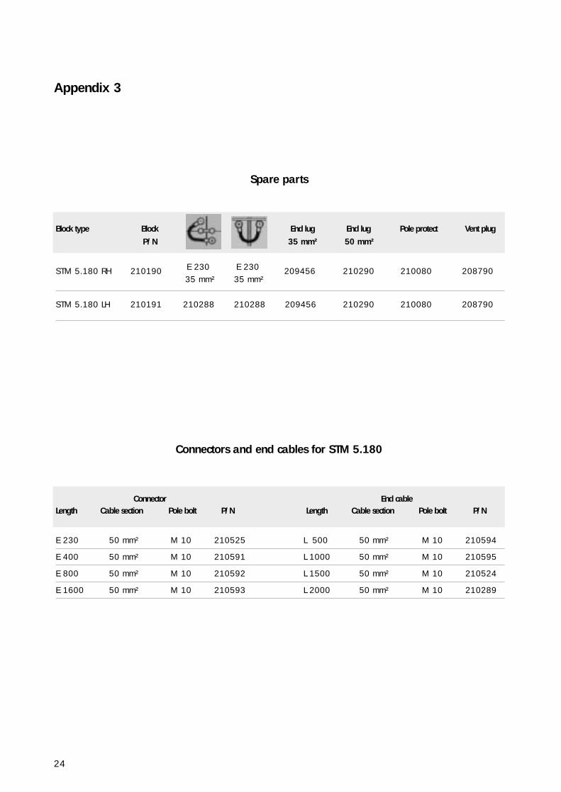
Spare parts
Block type Block End lug End lug Pole protect Vent plugP/N 35 mm² 50 mm²
STM 5.180 RH 210190 E 230 E 230 209456 210290 210080 20879035 mm² 35 mm²
STM 5.180 LH 210191 210288 210288 209456 210290 210080 208790
Connectors and end cables for STM 5.180
Connector End cableLength Cable section Pole bolt P/N Length Cable section Pole bolt P/N
E 230 50 mm² M 10 210525 L 500 50 mm² M 10 210594
E 400 50 mm² M 10 210591 L 1000 50 mm² M 10 210595
E 800 50 mm² M 10 210592 L 1500 50 mm² M 10 210524
E 1600 50 mm² M 10 210593 L 2000 50 mm² M 10 210289
24
Appendix 3
25
Accessories of the water filling system
Elbow ABS 208 740 orange, glued before fitting to plug
Adaptor ABS 209 635 orange, glued before fitting to plug
Glue 208 793 Tube Tensol n°12
Pipe 9 x 12 444 083 for small connections
Pipe 10 x 16 208 859 for connections > 200 mm
Collar 208 860 connecting pipe to elbow
Elbow polypro. 444 103 connecting pipe to pipe
Key 208 999 for all water filling plugs
Water coupling 208 854 (female) self closing
Water nipple 208 855 (male) self closing
Water coupling 208 751 (female) free pass
Water nipple 208 752 (male) free pass

Industrial Battery Group12, rue Sadi Carnot - 93170 Bagnolet - France
Tél. : + 33 (0)1 49 93 19 18 • Fax : + 33 (0)1 49 93 19 50 • www.saftbatteries.com Doc N° 04.01 - 51043.2
Informations in this document is subject to change without notice and becomes contractual only after written confirmation by Saft
Soci
été
Ano
nym
e au
cap
ital d
e 50
0 00
0 00
0 F
- RC
S Bo
bign
y B
383
703
873
- CSB
- Pr
inte
d in
Fra
nce