Embed Size (px)
Citation preview

T E C H N I C A L I N F O R M A T I O N
deTec4
Safety light curtain
IO-Link device and diagnostic data
Described product
deTec4
Manufacturer
SICK AGErwin-Sick-Str. 179183 WaldkirchGermany
Legal information
This work is protected by copyright. Any rights derived from the copyright shall bereserved for SICK AG. Reproduction of this document or parts of this document isonly permissible within the limits of the legal determination of Copyright Law. Any modi‐fication, abridgment or translation of this document is prohibited without the expresswritten permission of SICK AG.
The trademarks stated in this document are the property of their respective owner.
© SICK AG. All rights reserved.
Original document
This document is an original document of SICK AG.
2 T E C H N I C A L I N F O R M A T I O N | deTec4 8026725/2021-06-02 | SICKSubject to change without notice
Contents
1 About this document........................................................................ 51.1 Purpose of this document........................................................................ 51.2 Intended use............................................................................................. 51.3 Symbols and document conventions...................................................... 5
2 Description of IO-Link....................................................................... 6
3 Accessories for visualization, parameterization, and integra‐tion....................................................................................................... 7
4 Physical layer..................................................................................... 8
5 Process data...................................................................................... 95.1 PD in.......................................................................................................... 9
5.1.1 PD IN0...................................................................................... 115.1.2 PD IN1...................................................................................... 115.1.3 PD IN2...................................................................................... 125.1.4 PD IN3 – device and system status........................................ 13
5.2 PD OUT...................................................................................................... 14
6 Service data....................................................................................... 156.1 Device identification................................................................................. 15
6.1.1 Product name and manufacturer name................................. 156.1.2 Product text, serial number, hardware and firmware ver‐
sion........................................................................................... 156.1.3 Application-specific and device-specific name...................... 16
6.2 SICK device-specific information............................................................. 166.2.1 Operating hours counter......................................................... 166.2.2 Configuration status - receiver................................................ 166.2.3 Configuration status - sender................................................. 206.2.4 System information.................................................................. 206.2.5 System fault diagnosis............................................................ 216.2.6 Protective field areas of the system....................................... 246.2.7 Supply voltage.......................................................................... 256.2.8 Error history.............................................................................. 256.2.9 Shutdown history..................................................................... 266.2.10 Device identification................................................................ 276.2.11 Device data.............................................................................. 286.2.12 Device and operating times.................................................... 296.2.13 Beam data................................................................................ 306.2.14 Weak signal.............................................................................. 316.2.15 Beam alignment...................................................................... 336.2.16 Alignment quality..................................................................... 34
7 Example applications....................................................................... 36
CONTENTS
8026725/2021-06-02 | SICK T E C H N I C A L I N F O R M A T I O N | deTec4 3Subject to change without notice

7.1 Alignment and contamination.................................................................. 367.2 Changing LED display............................................................................... 367.3 Activation of the integrated laser alignment aid..................................... 377.4 Height measurement................................................................................ 38
8 Shutdown history and event codes................................................. 40
CONTENTS
4 T E C H N I C A L I N F O R M A T I O N | deTec4 8026725/2021-06-02 | SICKSubject to change without notice
1 About this document
1.1 Purpose of this document
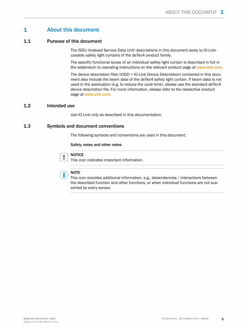
The ISDU (Indexed Service Data Unit) descriptions in this document apply to IO-Link-capable safety light curtains of the deTec4 product family.
The specific functional scope of an individual safety light curtain is described in full inthe addendum to operating instructions on the relevant product page at www.sick.com.
The device description files (IODD = IO-Link Device Description) contained in this docu‐ment also include the beam data of the deTec4 safety light curtain. If beam data is notused in the application (e.g. to reduce the cycle time), please use the standard deTec4device description file. For more information, please refer to the respective productpage at www.sick.com.
1.2 Intended use
Use IO-Link only as described in this documentation.
1.3 Symbols and document conventions
The following symbols and conventions are used in this document:
Safety notes and other notes
NOTICEThis icon indicates important information.
NOTEThis icon provides additional information, e.g., dependencies / interactions betweenthe described function and other functions, or when individual functions are not sup‐ported by every sensor.
ABOUT THIS DOCUMENT 1
8026725/2021-06-02 | SICK T E C H N I C A L I N F O R M A T I O N | deTec4 5Subject to change without notice
2 Description of IO-Link
IO-Link and control integration
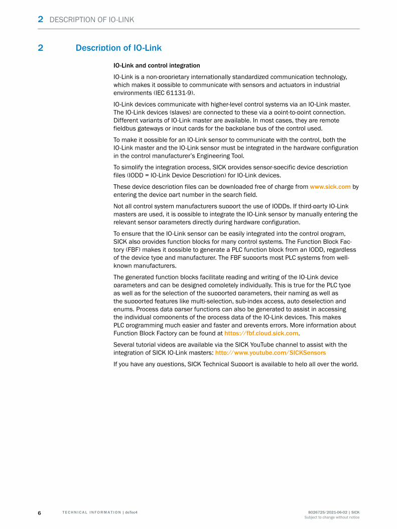
IO-Link is a non-proprietary internationally standardized communication technology,which makes it possible to communicate with sensors and actuators in industrialenvironments (IEC 61131-9).
IO-Link devices communicate with higher-level control systems via an IO-Link master.The IO-Link devices (slaves) are connected to these via a point-to-point connection.Different variants of IO-Link master are available. In most cases, they are remotefieldbus gateways or input cards for the backplane bus of the control used.
To make it possible for an IO-Link sensor to communicate with the control, both theIO-Link master and the IO-Link sensor must be integrated in the hardware configurationin the control manufacturer’s Engineering Tool.
To simplify the integration process, SICK provides sensor-specific device descriptionfiles (IODD = IO-Link Device Description) for IO-Link devices.
These device description files can be downloaded free of charge from www.sick.com byentering the device part number in the search field.
Not all control system manufacturers support the use of IODDs. If third-party IO-Linkmasters are used, it is possible to integrate the IO-Link sensor by manually entering therelevant sensor parameters directly during hardware configuration.
To ensure that the IO-Link sensor can be easily integrated into the control program,SICK also provides function blocks for many control systems. The Function Block Fac‐tory (FBF) makes it possible to generate a PLC function block from an IODD, regardlessof the device type and manufacturer. The FBF supports most PLC systems from well-known manufacturers.
The generated function blocks facilitate reading and writing of the IO-Link deviceparameters and can be designed completely individually. This is true for the PLC typeas well as for the selection of the supported parameters, their naming as well asthe supported features like multi-selection, sub-index access, auto deselection andenums. Process data parser functions can also be generated to assist in accessingthe individual components of the process data of the IO-Link devices. This makesPLC programming much easier and faster and prevents errors. More information aboutFunction Block Factory can be found at https://fbf.cloud.sick.com.
Several tutorial videos are available via the SICK YouTube channel to assist with theintegration of SICK IO-Link masters: http://www.youtube.com/SICKSensors
If you have any questions, SICK Technical Support is available to help all over the world.
2 DESCRIPTION OF IO-LINK
6 T E C H N I C A L I N F O R M A T I O N | deTec4 8026725/2021-06-02 | SICKSubject to change without notice
3 Accessories for visualization, parameterization, and integration
Using the SiLink2 master, you can easily connect IO-Link sensors from SICK to acomputer or a laptop via USB. You can then quickly and easily test or diagnose theconnected sensors using the SOPAS ET program (SICK Engineering Tool with graphicuser navigation and convenient visualization).
The corresponding visualization files (SDD = SOPAS Device Description) are availablefor many devices so that you can operate the IO-Link sensors using SOPAS ET.
You can download SOPAS ET and the device-specific SDDs directly and free of chargefrom the SICK homepage: www.sick.com
Various IO-Link masters are available from SICK for integrating IO-Link sensors usingfieldbus, see details at www.sick.com.
Furthermore, an IO-Link adapter (part number: 2092757) is required to connect thedeTec4 safety light curtain to an IO-Link master.
If you have any questions, SICK Technical Support is available to help all over the world.
ACCESSORIES FOR VISUALIZATION, PARAMETERIZATION, AND INTEGRATION 3
8026725/2021-06-02 | SICK T E C H N I C A L I N F O R M A T I O N | deTec4 7Subject to change without notice
4 Physical layer
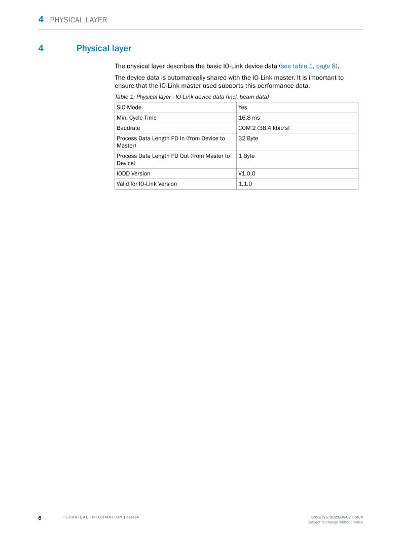
The physical layer describes the basic IO-Link device data (see table 1, page 8).
The device data is automatically shared with the IO-Link master. It is important toensure that the IO-Link master used supports this performance data.
Table 1: Physical layer - IO-Link device data (incl. beam data)
SIO Mode Yes
Min. Cycle Time 16,8 ms
Baudrate COM 2 (38,4 kbit/s)
Process Data Length PD In (from Device toMaster)
32 Byte
Process Data Length PD Out (from Master toDevice)
1 Byte
IODD Version V1.0.0
Valid for IO-Link Version 1.1.0
4 PHYSICAL LAYER
8 T E C H N I C A L I N F O R M A T I O N | deTec4 8026725/2021-06-02 | SICKSubject to change without notice
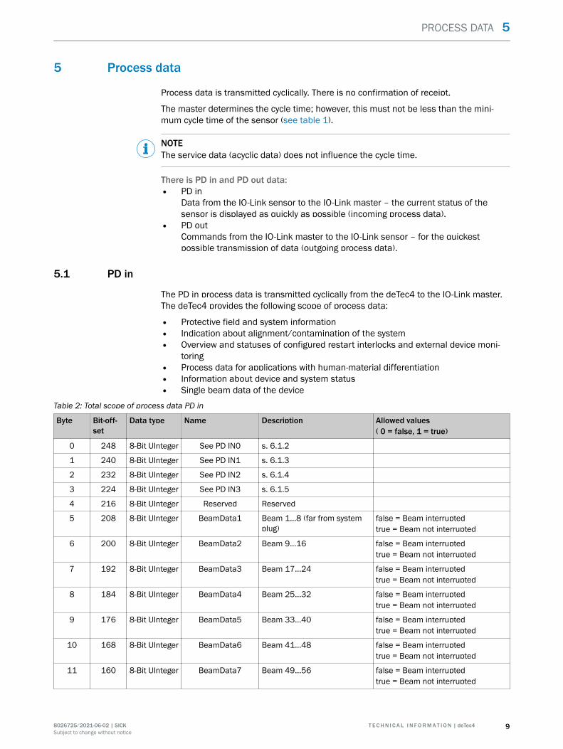
5 Process data
Process data is transmitted cyclically. There is no confirmation of receipt.
The master determines the cycle time; however, this must not be less than the mini‐mum cycle time of the sensor (see table 1).
NOTEThe service data (acyclic data) does not influence the cycle time.
There is PD in and PD out data:• PD in
Data from the IO-Link sensor to the IO-Link master – the current status of thesensor is displayed as quickly as possible (incoming process data).
• PD outCommands from the IO-Link master to the IO-Link sensor – for the quickestpossible transmission of data (outgoing process data).
5.1 PD in
The PD in process data is transmitted cyclically from the deTec4 to the IO-Link master.The deTec4 provides the following scope of process data:
• Protective field and system information• Indication about alignment/contamination of the system• Overview and statuses of configured restart interlocks and external device moni‐
toring• Process data for applications with human-material differentiation• Information about device and system status• Single beam data of the device
Table 2: Total scope of process data PD in
Byte Bit-off‐set
Data type Name Description Allowed values( 0 = false, 1 = true)
0 248 8-Bit UInteger See PD IN0 s. 6.1.2
1 240 8-Bit UInteger See PD IN1 s. 6.1.3
2 232 8-Bit UInteger See PD IN2 s. 6.1.4
3 224 8-Bit UInteger See PD IN3 s. 6.1.5
4 216 8-Bit UInteger Reserved Reserved
5 208 8-Bit UInteger BeamData1 Beam 1...8 (far from systemplug)
false = Beam interruptedtrue = Beam not interrupted
6 200 8-Bit UInteger BeamData2 Beam 9...16 false = Beam interruptedtrue = Beam not interrupted
7 192 8-Bit UInteger BeamData3 Beam 17...24 false = Beam interruptedtrue = Beam not interrupted
8 184 8-Bit UInteger BeamData4 Beam 25...32 false = Beam interruptedtrue = Beam not interrupted
9 176 8-Bit UInteger BeamData5 Beam 33...40 false = Beam interruptedtrue = Beam not interrupted
10 168 8-Bit UInteger BeamData6 Beam 41...48 false = Beam interruptedtrue = Beam not interrupted
11 160 8-Bit UInteger BeamData7 Beam 49...56 false = Beam interruptedtrue = Beam not interrupted
PROCESS DATA 5
8026725/2021-06-02 | SICK T E C H N I C A L I N F O R M A T I O N | deTec4 9Subject to change without notice
Byte Bit-off‐set
Data type Name Description Allowed values( 0 = false, 1 = true)
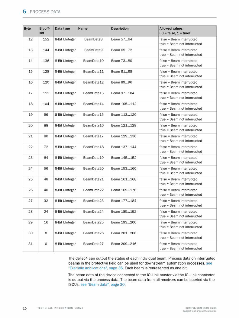
12 152 8-Bit UInteger BeamData8 Beam 57...64 false = Beam interruptedtrue = Beam not interrupted
13 144 8-Bit UInteger BeamData9 Beam 65...72 false = Beam interruptedtrue = Beam not interrupted
14 136 8-Bit UInteger BeamData10 Beam 73...80 false = Beam interruptedtrue = Beam not interrupted
15 128 8-Bit UInteger BeamData11 Beam 81...88 false = Beam interruptedtrue = Beam not interrupted
16 120 8-Bit UInteger BeamData12 Beam 89...96 false = Beam interruptedtrue = Beam not interrupted
17 112 8-Bit UInteger BeamData13 Beam 97...104 false = Beam interruptedtrue = Beam not interrupted
18 104 8-Bit UInteger BeamData14 Beam 105...112 false = Beam interruptedtrue = Beam not interrupted
19 96 8-Bit UInteger BeamData15 Beam 113...120 false = Beam interruptedtrue = Beam not interrupted
20 88 8-Bit UInteger BeamData16 Beam 121...128 false = Beam interruptedtrue = Beam not interrupted
21 80 8-Bit UInteger BeamData17 Beam 129...136 false = Beam interruptedtrue = Beam not interrupted
22 72 8-Bit UInteger BeamData18 Beam 137...144 false = Beam interruptedtrue = Beam not interrupted
23 64 8-Bit UInteger BeamData19 Beam 145...152 false = Beam interruptedtrue = Beam not interrupted
24 56 8-Bit UInteger BeamData20 Beam 153...160 false = Beam interruptedtrue = Beam not interrupted
25 48 8-Bit UInteger BeamData21 Beam 161...168 false = Beam interruptedtrue = Beam not interrupted
26 40 8-Bit UInteger BeamData22 Beam 169...176 false = Beam interruptedtrue = Beam not interrupted
27 32 8-Bit UInteger BeamData23 Beam 177...184 false = Beam interruptedtrue = Beam not interrupted
28 24 8-Bit UInteger BeamData24 Beam 185...192 false = Beam interruptedtrue = Beam not interrupted
29 16 8-Bit UInteger BeamData25 Beam 193...200 false = Beam interruptedtrue = Beam not interrupted
30 8 8-Bit UInteger BeamData26 Beam 201...208 false = Beam interruptedtrue = Beam not interrupted
31 0 8-Bit UInteger BeamData27 Beam 209...216 false = Beam interruptedtrue = Beam not interrupted
The deTec4 can output the status of each individual beam. Process data on interruptedbeams in the protective field can be used for downstream automation processes, see"Example applications", page 36. Each beam is represented as one bit.
The beam data of the device connected to the IO-Link master via the IO-Link connectoris output via the process data. The beam data from all receivers can be queried via theISDUs, see "Beam data", page 30.
5 PROCESS DATA
10 T E C H N I C A L I N F O R M A T I O N | deTec4 8026725/2021-06-02 | SICKSubject to change without notice
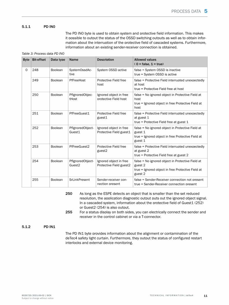
5.1.1 PD IN0
The PD IN0 byte is used to obtain system and protective field information. This makesit possible to output the status of the OSSD switching outputs as well as to obtain infor‐mation about the interruption of the protective field of cascaded systems. Furthermore,information about an existing sender-receiver connection is obtained.
Table 3: Process data PD IN0
Byte Bit-offset Data type Name Description Allowed values( 0 = false, 1 = true)
0 248 Boolean SystemOssdAc‐tive
System OSSD active false = System OSSD is inactivetrue = System OSSD is active
249 Boolean PfFreeHost Protective Field freehost
false = Protective Field interrupted unexpectedlyat hosttrue = Protective Field free at host
250 Boolean PfIgnoredObjec‐tHost
Ignored object in freeprotective Field host
false = No ignored object in Protective Field athosttrue = Ignored object in free Protective Field athost
251 Boolean PfFreeGuest1 Protective Field freeguest1
false = Protective Field interrupted unexpectedlyat guest 1true = Protective Field free at guest 1
252 Boolean PfIgnoredObject‐Guest1
Ignored object in freeProtective Field guest1
false = No ignored object in Protective Field atguest 1true = Ignored object in free Protective Field atguest 1
253 Boolean PfFreeGuest2 Protective Field freeguest2
false = Protective Field interrupted unexpectedlyat guest 2true = Protective Field free at guest 2
254 Boolean PfIgnoredObject‐Guest2
Ignored object in freeProtective Field guest2
false = No ignored object in Protective Field atguest 2true = Ignored object in free Protective Field atguest 2
255 Boolean SrLinkPresent Sender-receiver con‐nection present
false = Sender-Receiver connection not presenttrue = Sender-Receiver connection present
250 As long as the ESPE detects an object that is smaller than the set reducedresolution, the application diagnostic output puts out the ignored object signal.In a cascaded system, information about the protective field of Guest1 (252)or Guest2 (254) is also output.
255 For a status display on both sides, you can electrically connect the sender andreceiver in the control cabinet or via a T-connector.
5.1.2 PD IN1
The PD IN1 byte provides information about the alignment or contamination of thedeTec4 safety light curtain. Furthermore, they output the status of configured restartinterlocks and external device monitoring.
PROCESS DATA 5
8026725/2021-06-02 | SICK T E C H N I C A L I N F O R M A T I O N | deTec4 11Subject to change without notice
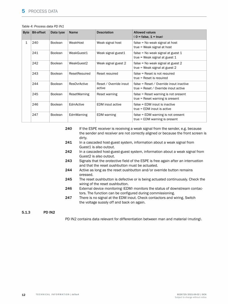
Table 4: Process data PD IN1
Byte Bit-offset Data type Name Description Allowed values( 0 = false, 1 = true)
1 240 Boolean WeakHost Weak signal host false = No weak signal at hosttrue = Weak signal at host
241 Boolean WeakGuest1 Weak signal guest1 false = No weak signal at guest 1true = Weak signal at guest 1
242 Boolean WeakGuest2 Weak signal guest 2 false = No weak signal at guest 2true = Weak signal at guest 2
243 Boolean ResetRequired Reset required false = Reset is not requiredtrue = Reset is required
244 Boolean ResOvrActive Reset / Override inputactive
false = Reset / Override input inactivetrue = Reset / Override input active
245 Boolean ResetWarning Reset warning false = Reset warning is not presenttrue = Reset warning is present
246 Boolean EdmActive EDM input active false = EDM input is inactivetrue = EDM input is active
247 Boolean EdmWarning EDM warning false = EDM warning is not presenttrue = EDM warning is present
240 If the ESPE receiver is receiving a weak signal from the sender, e.g. becausethe sender and receiver are not correctly aligned or because the front screen isdirty.
241 In a cascaded host-guest system, information about a weak signal fromGuest1 is also output.
242 In a cascaded host-guest-guest system, information about a weak signal fromGuest2 is also output.
243 Signals that the protective field of the ESPE is free again after an interruptionand that the reset pushbutton must be actuated.
244 Active as long as the reset pushbutton and/or override button remainspressed.
245 The reset pushbutton is defective or is being actuated continuously. Check thewiring of the reset pushbutton.
246 External device monitoring (EDM) monitors the status of downstream contac‐tors. The function can be configured during commissioning.
247 There is no signal at the EDM input. Check contactors and wiring. Switchthe voltage supply off and back on again.
5.1.3 PD IN2
PD IN2 contains data relevant for differentiation between man and material (muting).
5 PROCESS DATA
12 T E C H N I C A L I N F O R M A T I O N | deTec4 8026725/2021-06-02 | SICKSubject to change without notice
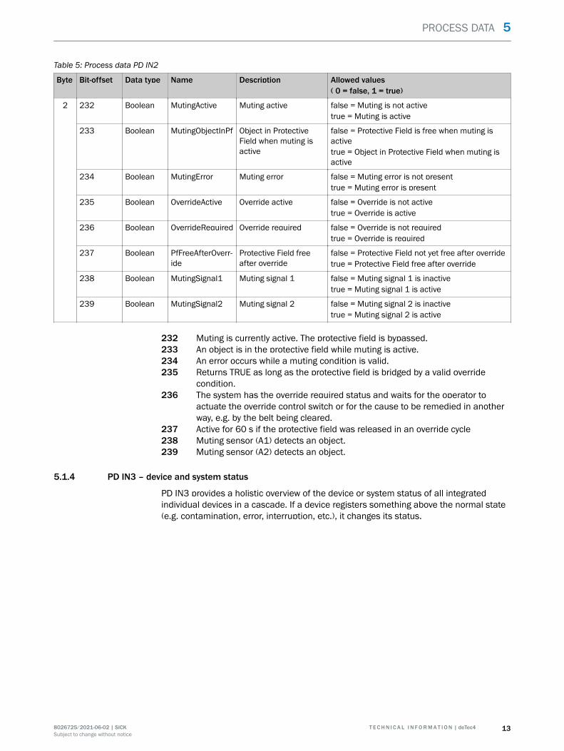
Table 5: Process data PD IN2
Byte Bit-offset Data type Name Description Allowed values( 0 = false, 1 = true)
2 232 Boolean MutingActive Muting active false = Muting is not activetrue = Muting is active
233 Boolean MutingObjectInPf Object in ProtectiveField when muting isactive
false = Protective Field is free when muting isactivetrue = Object in Protective Field when muting isactive
234 Boolean MutingError Muting error false = Muting error is not presenttrue = Muting error is present
235 Boolean OverrideActive Override active false = Override is not activetrue = Override is active
236 Boolean OverrideRequired Override required false = Override is not requiredtrue = Override is required
237 Boolean PfFreeAfterOverr‐ide
Protective Field freeafter override
false = Protective Field not yet free after overridetrue = Protective Field free after override
238 Boolean MutingSignal1 Muting signal 1 false = Muting signal 1 is inactivetrue = Muting signal 1 is active
239 Boolean MutingSignal2 Muting signal 2 false = Muting signal 2 is inactivetrue = Muting signal 2 is active
232 Muting is currently active. The protective field is bypassed.233 An object is in the protective field while muting is active.234 An error occurs while a muting condition is valid.235 Returns TRUE as long as the protective field is bridged by a valid override
condition.236 The system has the override required status and waits for the operator to
actuate the override control switch or for the cause to be remedied in anotherway, e.g. by the belt being cleared.
237 Active for 60 s if the protective field was released in an override cycle238 Muting sensor (A1) detects an object.239 Muting sensor (A2) detects an object.
5.1.4 PD IN3 – device and system status
PD IN3 provides a holistic overview of the device or system status of all integratedindividual devices in a cascade. If a device registers something above the normal state(e.g. contamination, error, interruption, etc.), it changes its status.
PROCESS DATA 5
8026725/2021-06-02 | SICK T E C H N I C A L I N F O R M A T I O N | deTec4 13Subject to change without notice
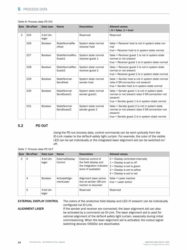
Table 6: Process data PD IN3
Byte Bit-offset Data type Name Description Allowed values( 0 = false, 1 = true)
3 224 2-bit UIn‐teger
Reserved Reserved
226 Boolean StateNormalRe‐cHost
System state normalreceiver host
false = Receiver host is not in system state nor‐maltrue = Receiver host is in system state normal
227 Boolean StateNormalRec‐Guest1
System state normalreceiver guest 1
false = Receiver guest 1 is not in system statenormal or not presenttrue = Receiver guest 1 is in system state normal
228 Boolean StateNormalRec‐Guest2
System state normalreceiver guest 2
false = Receiver guest 2 is not in system statenormal or not presenttrue = Receiver guest 2 is in system state normal
229 Boolean StateNormal‐SendHost
System state normalsender host
false = Sender host is not in system state normal(also if SR-connection not present)true = Sender host is in system state normal
230 Boolean StateNormal‐SendGuest1
System state normalsender guest1
false = Sender guest 1 is not in system statenormal or not present (also if SR-connection notpresent)true = Sender guest 1 is in system state normal
231 Boolean StateNormal‐SendGuest2
System state normalsender guest 2
false = Sender guest 2 is not in system statenormal or not present (also if SR-connection notpresent)true = Sender guest 2 is in system state normal
5.2 PD OUT
Using the PD out process data, control commands can be sent cyclically from theIO-Link master to the deTec4 safety light curtain. For example, the color of the visibleLED can be set individually or the integrated laser alignment aid can be switched on/off.
Table 7: Process data PD OUT
Byte Bit-offset Data type Name Description Allowed values
0 0 4-bit UIn‐teger
ExternalDisplay‐Control
External control ofthe field display andthe integration indicatorlamp (if available)
0 = Display controlled internally1 = Display is set to off2 = Display is set to green3 = Display is set to yellow4 = Display is set to red
4 Boolean ActivateAlign‐mentLaser
Alignment laser activa‐tion at sender (SR-con‐nection is required)
false = Laser inactivetrue = Laser active
5 3-bit UIn‐teger
Reserved Reserved
EXTERNAL DISPLAY CONTROL The colors of the protective field display and LED (if present) can be individuallyconfigured via IO-Link.
ALIGNMENT LASER If the sender and receiver are connected, the laser alignment aid can alsobe activated by a command via IO-Link. The laser alignment aid is used foroptimal alignment of the deTec4 safety light curtain, especially during initialcommissioning. When the laser alignment aid is activated, the output signalswitching devices (OSSDs) are deactivated.
5 PROCESS DATA
14 T E C H N I C A L I N F O R M A T I O N | deTec4 8026725/2021-06-02 | SICKSubject to change without notice
6 Service data
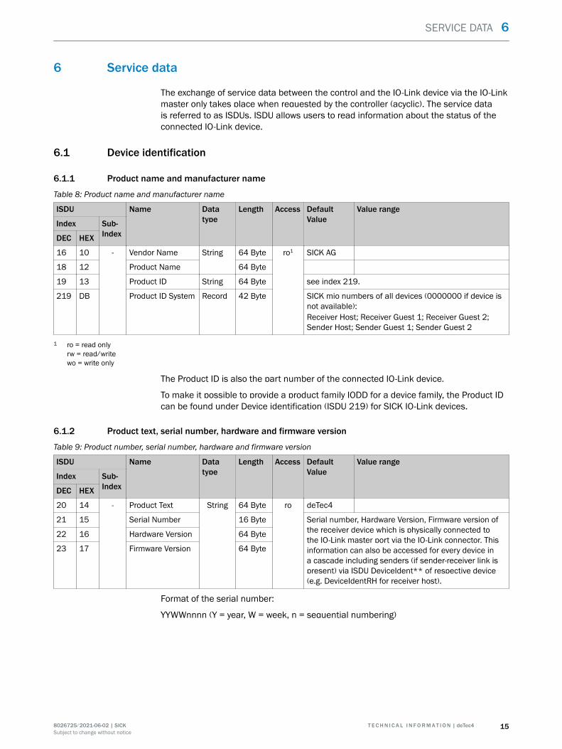
The exchange of service data between the control and the IO-Link device via the IO-Linkmaster only takes place when requested by the controller (acyclic). The service datais referred to as ISDUs. ISDU allows users to read information about the status of theconnected IO-Link device.
6.1 Device identification
6.1.1 Product name and manufacturer name
Table 8: Product name and manufacturer name
ISDU Name Datatype
Length Access DefaultValue
Value range
Index Sub-IndexDEC HEX
16 10 - Vendor Name String 64 Byte ro1 SICK AG
18 12 Product Name 64 Byte
19 13 Product ID String 64 Byte see index 219.
219 DB Product ID System Record 42 Byte SICK mio numbers of all devices (0000000 if device isnot available):Receiver Host; Receiver Guest 1; Receiver Guest 2;Sender Host; Sender Guest 1; Sender Guest 2
1 ro = read onlyrw = read/writewo = write only
The Product ID is also the part number of the connected IO-Link device.
To make it possible to provide a product family IODD for a device family, the Product IDcan be found under Device identification (ISDU 219) for SICK IO-Link devices.
6.1.2 Product text, serial number, hardware and firmware version
Table 9: Product number, serial number, hardware and firmware version
ISDU Name Datatype
Length Access DefaultValue
Value range
Index Sub-IndexDEC HEX
20 14 - Product Text String 64 Byte ro deTec4
21 15 Serial Number 16 Byte Serial number, Hardware Version, Firmware version ofthe receiver device which is physically connected tothe IO-Link master port via the IO-Link connector. Thisinformation can also be accessed for every device ina cascade including senders (if sender-receiver link ispresent) via ISDU DeviceIdent** of respective device(e.g. DeviceIdentRH for receiver host).
22 16 Hardware Version 64 Byte
23 17 Firmware Version 64 Byte
Format of the serial number:
YYWWnnnn (Y = year, W = week, n = sequential numbering)
SERVICE DATA 6
8026725/2021-06-02 | SICK T E C H N I C A L I N F O R M A T I O N | deTec4 15Subject to change without notice
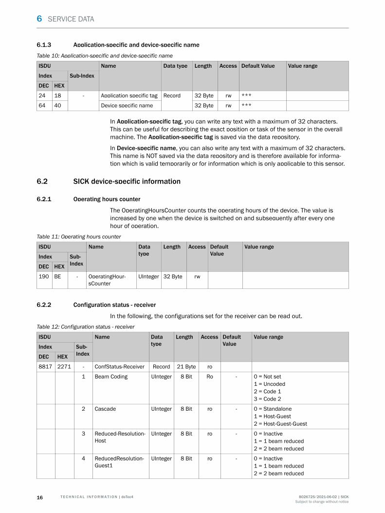
6.1.3 Application-specific and device-specific name
Table 10: Application-specific and device-specific name
ISDU Name Data type Length Access Default Value Value range
Index Sub-Index
DEC HEX
24 18 - Application specific tag Record 32 Byte rw ***
64 40 Device specific name 32 Byte rw ***
In Application-specific tag, you can write any text with a maximum of 32 characters.This can be useful for describing the exact position or task of the sensor in the overallmachine. The Application-specific tag is saved via the data repository.
In Device-specific name, you can also write any text with a maximum of 32 characters.This name is NOT saved via the data repository and is therefore available for informa‐tion which is valid temporarily or for information which is only applicable to this sensor.
6.2 SICK device-specific information
6.2.1 Operating hours counter
The OperatingHoursCounter counts the operating hours of the device. The value isincreased by one when the device is switched on and subsequently after every onehour of operation.
Table 11: Operating hours counter
ISDU Name Datatype
Length Access DefaultValue
Value range
Index Sub-IndexDEC HEX
190 BE - OperatingHour‐sCounter
UInteger 32 Byte rw
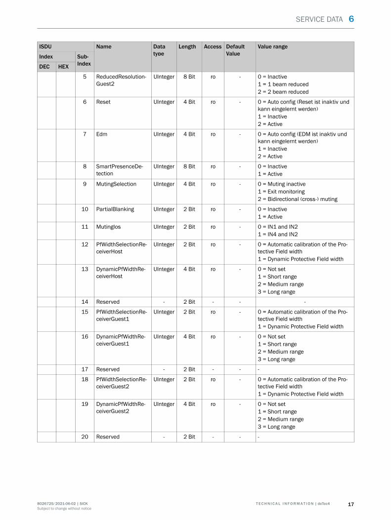
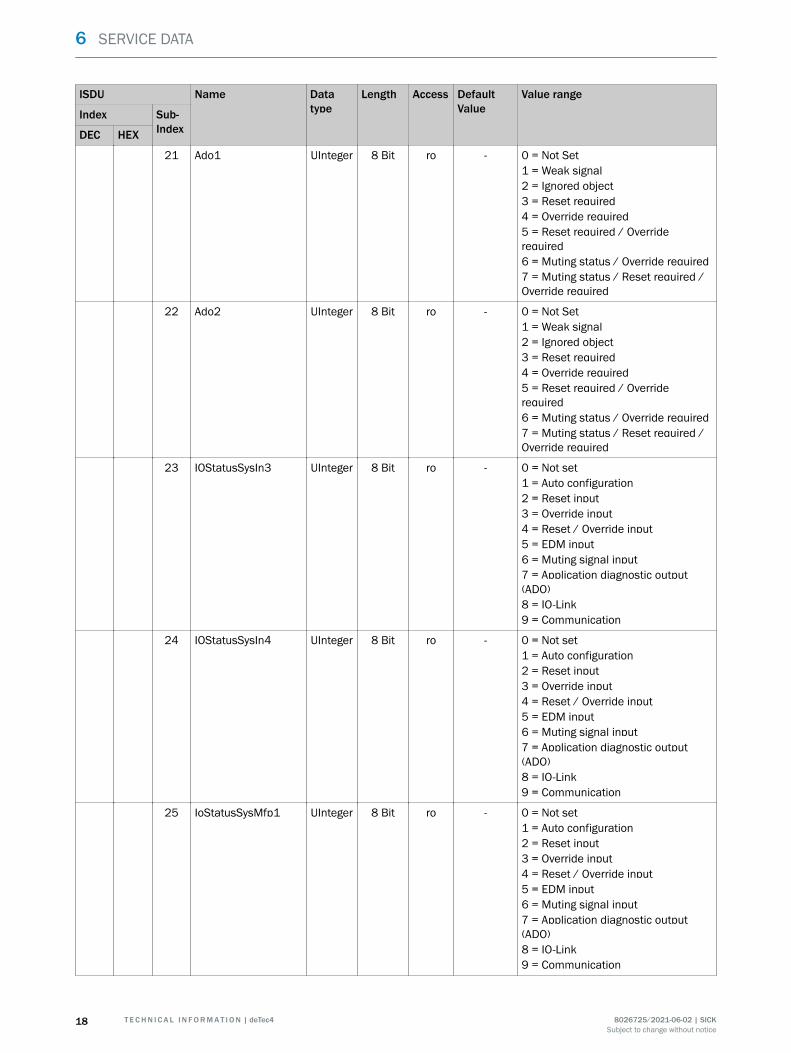
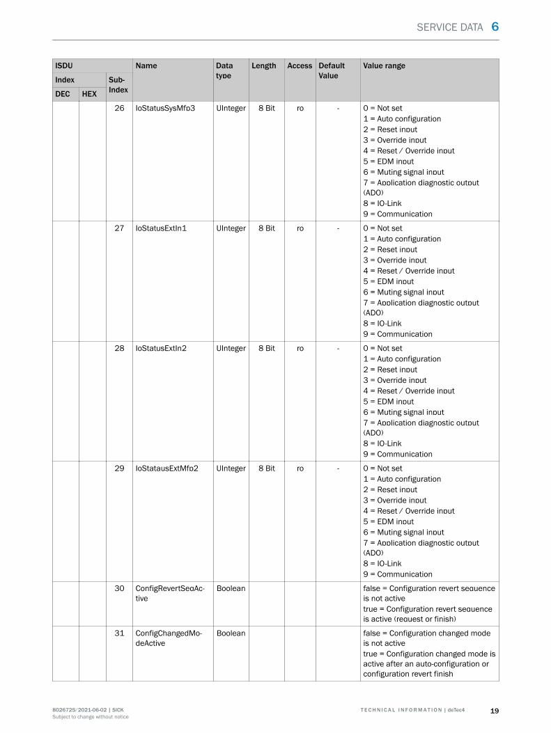
6.2.2 Configuration status - receiver
In the following, the configurations set for the receiver can be read out.
Table 12: Configuration status - receiver
ISDU Name Datatype
Length Access DefaultValue
Value range
Index Sub-IndexDEC HEX
8817 2271 - ConfStatus-Receiver Record 21 Byte ro
1 Beam Coding UInteger 8 Bit Ro - 0 = Not set1 = Uncoded2 = Code 13 = Code 2
2 Cascade UInteger 8 Bit ro - 0 = Standalone1 = Host-Guest2 = Host-Guest-Guest
3 Reduced-Resolution‐Host
UInteger 8 Bit ro - 0 = Inactive1 = 1 beam reduced2 = 2 beam reduced
4 ReducedResolution‐Guest1
UInteger 8 Bit ro - 0 = Inactive1 = 1 beam reduced2 = 2 beam reduced
6 SERVICE DATA
16 T E C H N I C A L I N F O R M A T I O N | deTec4 8026725/2021-06-02 | SICKSubject to change without notice
ISDU Name Datatype
Length Access DefaultValue
Value range
Index Sub-IndexDEC HEX
5 ReducedResolution‐Guest2
UInteger 8 Bit ro - 0 = Inactive1 = 1 beam reduced2 = 2 beam reduced
6 Reset UInteger 4 Bit ro - 0 = Auto config (Reset ist inaktiv undkann eingelernt werden)1 = Inactive2 = Active
7 Edm UInteger 4 Bit ro - 0 = Auto config (EDM ist inaktiv undkann eingelernt werden)1 = Inactive2 = Active
8 SmartPresenceDe‐tection
UInteger 8 Bit ro - 0 = Inactive1 = Active
9 MutingSelection UInteger 4 Bit ro - 0 = Muting inactive1 = Exit monitoring2 = Bidirectional (cross-) muting
10 PartialBlanking UInteger 2 Bit ro - 0 = Inactive1 = Active
11 MutingIos UInteger 2 Bit ro - 0 = IN1 and IN21 = IN4 and IN2
12 PfWidthSelectionRe‐ceiverHost
UInteger 2 Bit ro - 0 = Automatic calibration of the Pro‐tective Field width1 = Dynamic Protective Field width
13 DynamicPfWidthRe‐ceiverHost
UInteger 4 Bit ro - 0 = Not set1 = Short range2 = Medium range3 = Long range
14 Reserved - 2 Bit - - -
15 PfWidthSelectionRe‐ceiverGuest1
UInteger 2 Bit ro - 0 = Automatic calibration of the Pro‐tective Field width1 = Dynamic Protective Field width
16 DynamicPfWidthRe‐ceiverGuest1
UInteger 4 Bit ro - 0 = Not set1 = Short range2 = Medium range3 = Long range
17 Reserved - 2 Bit - - -
18 PfWidthSelectionRe‐ceiverGuest2
UInteger 2 Bit ro - 0 = Automatic calibration of the Pro‐tective Field width1 = Dynamic Protective Field width
19 DynamicPfWidthRe‐ceiverGuest2
UInteger 4 Bit ro - 0 = Not set1 = Short range2 = Medium range3 = Long range
20 Reserved - 2 Bit - - -
SERVICE DATA 6
8026725/2021-06-02 | SICK T E C H N I C A L I N F O R M A T I O N | deTec4 17Subject to change without notice
ISDU Name Datatype
Length Access DefaultValue
Value range
Index Sub-IndexDEC HEX
21 Ado1 UInteger 8 Bit ro - 0 = Not Set1 = Weak signal2 = Ignored object3 = Reset required4 = Override required5 = Reset required / Overriderequired6 = Muting status / Override required7 = Muting status / Reset required /Override required
22 Ado2 UInteger 8 Bit ro - 0 = Not Set1 = Weak signal2 = Ignored object3 = Reset required4 = Override required5 = Reset required / Overriderequired6 = Muting status / Override required7 = Muting status / Reset required /Override required
23 IOStatusSysIn3 UInteger 8 Bit ro - 0 = Not set1 = Auto configuration2 = Reset input3 = Override input4 = Reset / Override input5 = EDM input6 = Muting signal input7 = Application diagnostic output(ADO)8 = IO-Link9 = Communication
24 IOStatusSysIn4 UInteger 8 Bit ro - 0 = Not set1 = Auto configuration2 = Reset input3 = Override input4 = Reset / Override input5 = EDM input6 = Muting signal input7 = Application diagnostic output(ADO)8 = IO-Link9 = Communication
25 IoStatusSysMfp1 UInteger 8 Bit ro - 0 = Not set1 = Auto configuration2 = Reset input3 = Override input4 = Reset / Override input5 = EDM input6 = Muting signal input7 = Application diagnostic output(ADO)8 = IO-Link9 = Communication
6 SERVICE DATA
18 T E C H N I C A L I N F O R M A T I O N | deTec4 8026725/2021-06-02 | SICKSubject to change without notice
ISDU Name Datatype
Length Access DefaultValue
Value range
Index Sub-IndexDEC HEX
26 IoStatusSysMfp3 UInteger 8 Bit ro - 0 = Not set1 = Auto configuration2 = Reset input3 = Override input4 = Reset / Override input5 = EDM input6 = Muting signal input7 = Application diagnostic output(ADO)8 = IO-Link9 = Communication
27 IoStatusExtIn1 UInteger 8 Bit ro - 0 = Not set1 = Auto configuration2 = Reset input3 = Override input4 = Reset / Override input5 = EDM input6 = Muting signal input7 = Application diagnostic output(ADO)8 = IO-Link9 = Communication
28 IoStatusExtIn2 UInteger 8 Bit ro - 0 = Not set1 = Auto configuration2 = Reset input3 = Override input4 = Reset / Override input5 = EDM input6 = Muting signal input7 = Application diagnostic output(ADO)8 = IO-Link9 = Communication
29 IoStatausExtMfp2 UInteger 8 Bit ro - 0 = Not set1 = Auto configuration2 = Reset input3 = Override input4 = Reset / Override input5 = EDM input6 = Muting signal input7 = Application diagnostic output(ADO)8 = IO-Link9 = Communication
30 ConfigRevertSeqAc‐tive
Boolean false = Configuration revert sequenceis not activetrue = Configuration revert sequenceis active (request or finish)
31 ConfigChangedMo‐deActive
Boolean false = Configuration changed modeis not activetrue = Configuration changed mode isactive after an auto-configuration orconfiguration revert finish
SERVICE DATA 6
8026725/2021-06-02 | SICK T E C H N I C A L I N F O R M A T I O N | deTec4 19Subject to change without notice
ISDU Name Datatype
Length Access DefaultValue
Value range
Index Sub-IndexDEC HEX
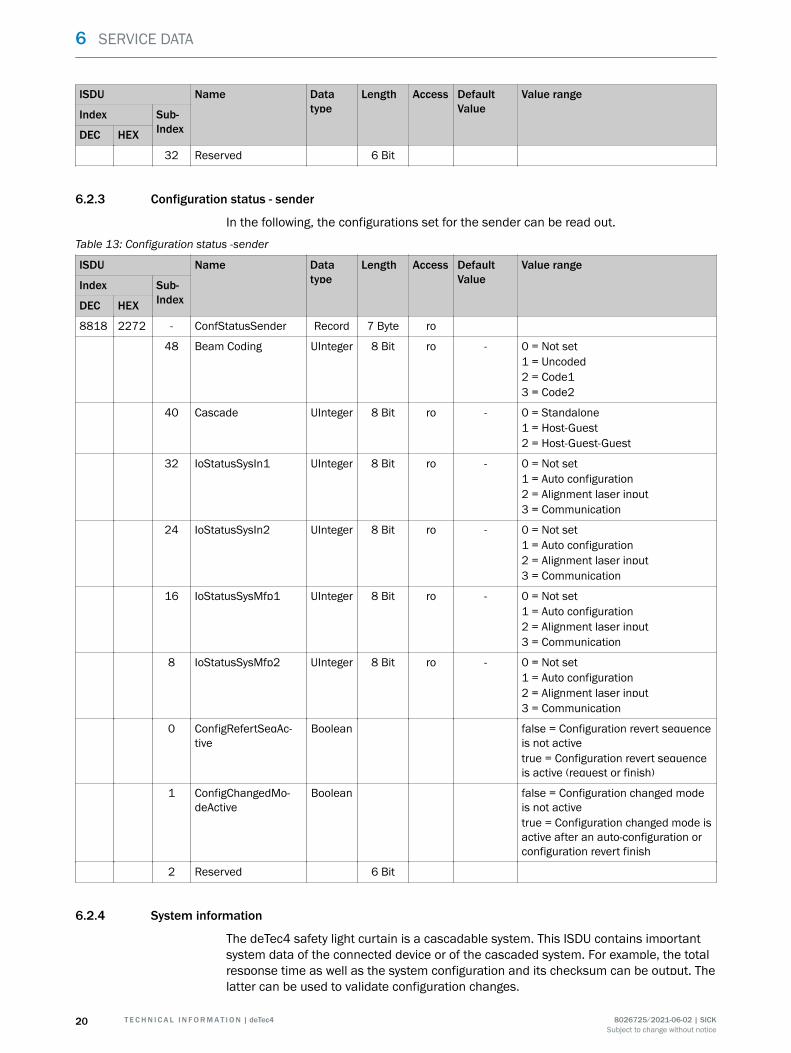
32 Reserved 6 Bit
6.2.3 Configuration status - sender
In the following, the configurations set for the sender can be read out.
Table 13: Configuration status -sender
ISDU Name Datatype
Length Access DefaultValue
Value range
Index Sub-IndexDEC HEX
8818 2272 - ConfStatusSender Record 7 Byte ro
48 Beam Coding UInteger 8 Bit ro - 0 = Not set1 = Uncoded2 = Code13 = Code2
40 Cascade UInteger 8 Bit ro - 0 = Standalone1 = Host-Guest2 = Host-Guest-Guest
32 IoStatusSysIn1 UInteger 8 Bit ro - 0 = Not set1 = Auto configuration2 = Alignment laser input3 = Communication
24 IoStatusSysIn2 UInteger 8 Bit ro - 0 = Not set1 = Auto configuration2 = Alignment laser input3 = Communication
16 IoStatusSysMfp1 UInteger 8 Bit ro - 0 = Not set1 = Auto configuration2 = Alignment laser input3 = Communication
8 IoStatusSysMfp2 UInteger 8 Bit ro - 0 = Not set1 = Auto configuration2 = Alignment laser input3 = Communication
0 ConfigRefertSeqAc‐tive
Boolean false = Configuration revert sequenceis not activetrue = Configuration revert sequenceis active (request or finish)
1 ConfigChangedMo‐deActive
Boolean false = Configuration changed modeis not activetrue = Configuration changed mode isactive after an auto-configuration orconfiguration revert finish
2 Reserved 6 Bit
6.2.4 System information
The deTec4 safety light curtain is a cascadable system. This ISDU contains importantsystem data of the connected device or of the cascaded system. For example, the totalresponse time as well as the system configuration and its checksum can be output. Thelatter can be used to validate configuration changes.
6 SERVICE DATA
20 T E C H N I C A L I N F O R M A T I O N | deTec4 8026725/2021-06-02 | SICKSubject to change without notice
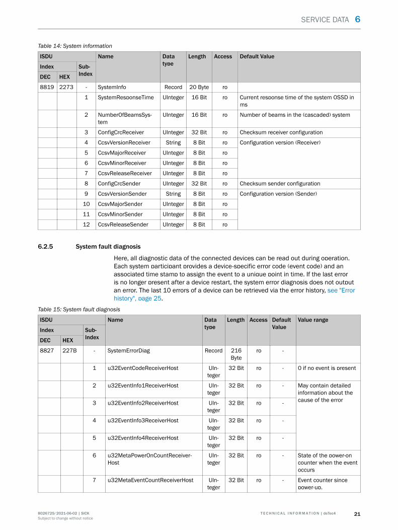
Table 14: System information
ISDU Name Datatype
Length Access Default Value
Index Sub-IndexDEC HEX
8819 2273 - SystemInfo Record 20 Byte ro
1 SystemResponseTime UInteger 16 Bit ro Current response time of the system OSSD inms
2 NumberOfBeamsSys‐tem
UInteger 16 Bit ro Number of beams in the (cascaded) system
3 ConfigCrcReceiver UInteger 32 Bit ro Checksum receiver configuration
4 CcsvVersionReceiver String 8 Bit ro Configuration version (Receiver)
5 CcsvMajorReceiver UInteger 8 Bit ro
6 CcsvMinorReceiver UInteger 8 Bit ro
7 CcsvReleaseReceiver UInteger 8 Bit ro
8 ConfigCrcSender UInteger 32 Bit ro Checksum sender configuration
9 CcsvVersionSender String 8 Bit ro Configuration version (Sender)
10 CcsvMajorSender UInteger 8 Bit ro
11 CcsvMinorSender UInteger 8 Bit ro
12 CcsvReleaseSender UInteger 8 Bit ro
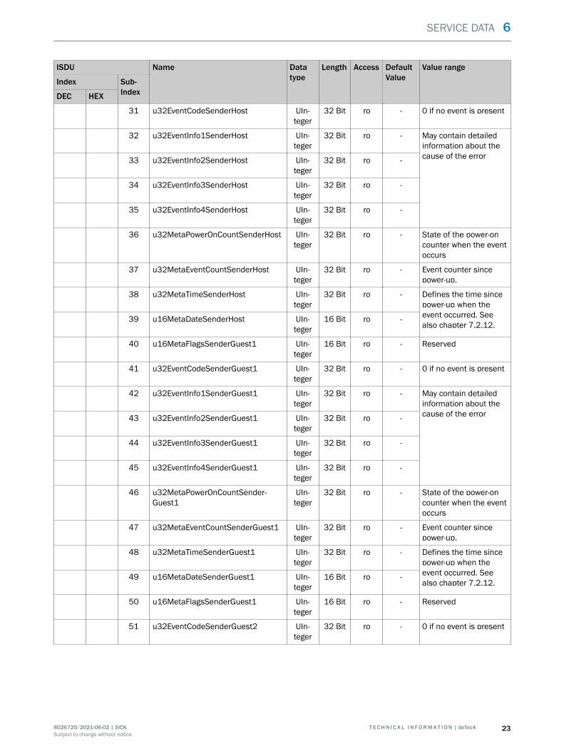
6.2.5 System fault diagnosis
Here, all diagnostic data of the connected devices can be read out during operation.Each system participant provides a device-specific error code (event code) and anassociated time stamp to assign the event to a unique point in time. If the last erroris no longer present after a device restart, the system error diagnosis does not outputan error. The last 10 errors of a device can be retrieved via the error history, see "Errorhistory", page 25.
Table 15: System fault diagnosis
ISDU Name Datatype
Length Access DefaultValue
Value range
Index Sub-IndexDEC HEX
8827 227B - SystemErrorDiag Record 216Byte
ro -
1 u32EventCodeReceiverHost UIn‐teger
32 Bit ro - 0 if no event is present
2 u32EventInfo1ReceiverHost UIn‐teger
32 Bit ro - May contain detailedinformation about thecause of the error3 u32EventInfo2ReceiverHost UIn‐
teger32 Bit ro -
4 u32EventInfo3ReceiverHost UIn‐teger
32 Bit ro -
5 u32EventInfo4ReceiverHost UIn‐teger
32 Bit ro -
6 u32MetaPowerOnCountReceiver‐Host
UIn‐teger
32 Bit ro - State of the power-oncounter when the eventoccurs
7 u32MetaEventCountReceiverHost UIn‐teger
32 Bit ro - Event counter sincepower-up.
SERVICE DATA 6
8026725/2021-06-02 | SICK T E C H N I C A L I N F O R M A T I O N | deTec4 21Subject to change without notice
ISDU Name Datatype
Length Access DefaultValue
Value range
Index Sub-IndexDEC HEX
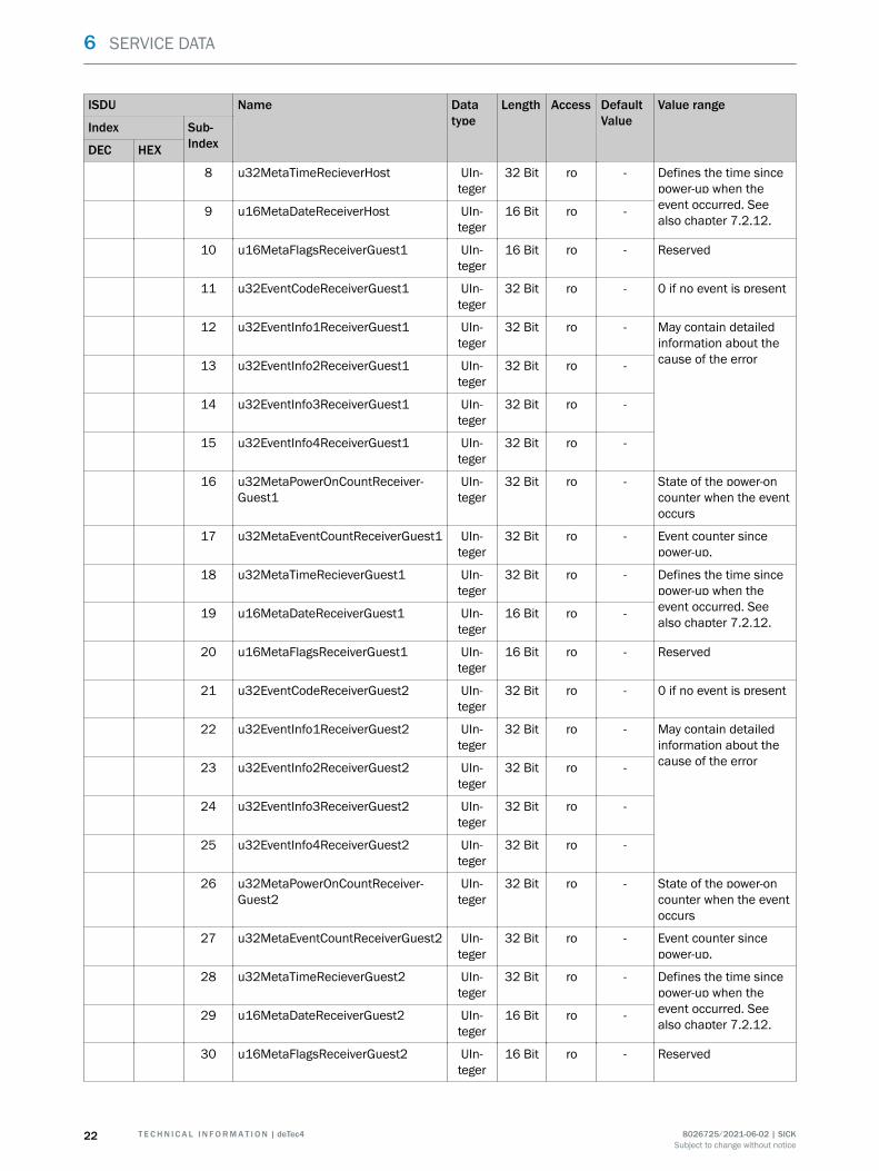
8 u32MetaTimeRecieverHost UIn‐teger
32 Bit ro - Defines the time sincepower-up when theevent occurred. Seealso chapter 7.2.12.
9 u16MetaDateReceiverHost UIn‐teger
16 Bit ro -
10 u16MetaFlagsReceiverGuest1 UIn‐teger
16 Bit ro - Reserved
11 u32EventCodeReceiverGuest1 UIn‐teger
32 Bit ro - 0 if no event is present
12 u32EventInfo1ReceiverGuest1 UIn‐teger
32 Bit ro - May contain detailedinformation about thecause of the error13 u32EventInfo2ReceiverGuest1 UIn‐
teger32 Bit ro -
14 u32EventInfo3ReceiverGuest1 UIn‐teger
32 Bit ro -
15 u32EventInfo4ReceiverGuest1 UIn‐teger
32 Bit ro -
16 u32MetaPowerOnCountReceiver‐Guest1
UIn‐teger
32 Bit ro - State of the power-oncounter when the eventoccurs
17 u32MetaEventCountReceiverGuest1 UIn‐teger
32 Bit ro - Event counter sincepower-up.
18 u32MetaTimeRecieverGuest1 UIn‐teger
32 Bit ro - Defines the time sincepower-up when theevent occurred. Seealso chapter 7.2.12.
19 u16MetaDateReceiverGuest1 UIn‐teger
16 Bit ro -
20 u16MetaFlagsReceiverGuest1 UIn‐teger
16 Bit ro - Reserved
21 u32EventCodeReceiverGuest2 UIn‐teger
32 Bit ro - 0 if no event is present
22 u32EventInfo1ReceiverGuest2 UIn‐teger
32 Bit ro - May contain detailedinformation about thecause of the error23 u32EventInfo2ReceiverGuest2 UIn‐
teger32 Bit ro -
24 u32EventInfo3ReceiverGuest2 UIn‐teger
32 Bit ro -
25 u32EventInfo4ReceiverGuest2 UIn‐teger
32 Bit ro -
26 u32MetaPowerOnCountReceiver‐Guest2
UIn‐teger
32 Bit ro - State of the power-oncounter when the eventoccurs
27 u32MetaEventCountReceiverGuest2 UIn‐teger
32 Bit ro - Event counter sincepower-up.
28 u32MetaTimeRecieverGuest2 UIn‐teger
32 Bit ro - Defines the time sincepower-up when theevent occurred. Seealso chapter 7.2.12.
29 u16MetaDateReceiverGuest2 UIn‐teger
16 Bit ro -
30 u16MetaFlagsReceiverGuest2 UIn‐teger
16 Bit ro - Reserved
6 SERVICE DATA
22 T E C H N I C A L I N F O R M A T I O N | deTec4 8026725/2021-06-02 | SICKSubject to change without notice
ISDU Name Datatype
Length Access DefaultValue
Value range
Index Sub-IndexDEC HEX
31 u32EventCodeSenderHost UIn‐teger
32 Bit ro - 0 if no event is present
32 u32EventInfo1SenderHost UIn‐teger
32 Bit ro - May contain detailedinformation about thecause of the error33 u32EventInfo2SenderHost UIn‐
teger32 Bit ro -
34 u32EventInfo3SenderHost UIn‐teger
32 Bit ro -
35 u32EventInfo4SenderHost UIn‐teger
32 Bit ro -
36 u32MetaPowerOnCountSenderHost UIn‐teger
32 Bit ro - State of the power-oncounter when the eventoccurs
37 u32MetaEventCountSenderHost UIn‐teger
32 Bit ro - Event counter sincepower-up.
38 u32MetaTimeSenderHost UIn‐teger
32 Bit ro - Defines the time sincepower-up when theevent occurred. Seealso chapter 7.2.12.
39 u16MetaDateSenderHost UIn‐teger
16 Bit ro -
40 u16MetaFlagsSenderGuest1 UIn‐teger
16 Bit ro - Reserved
41 u32EventCodeSenderGuest1 UIn‐teger
32 Bit ro - 0 if no event is present
42 u32EventInfo1SenderGuest1 UIn‐teger
32 Bit ro - May contain detailedinformation about thecause of the error43 u32EventInfo2SenderGuest1 UIn‐
teger32 Bit ro -
44 u32EventInfo3SenderGuest1 UIn‐teger
32 Bit ro -
45 u32EventInfo4SenderGuest1 UIn‐teger
32 Bit ro -
46 u32MetaPowerOnCountSender‐Guest1
UIn‐teger
32 Bit ro - State of the power-oncounter when the eventoccurs
47 u32MetaEventCountSenderGuest1 UIn‐teger
32 Bit ro - Event counter sincepower-up.
48 u32MetaTimeSenderGuest1 UIn‐teger
32 Bit ro - Defines the time sincepower-up when theevent occurred. Seealso chapter 7.2.12.
49 u16MetaDateSenderGuest1 UIn‐teger
16 Bit ro -
50 u16MetaFlagsSenderGuest1 UIn‐teger
16 Bit ro - Reserved
51 u32EventCodeSenderGuest2 UIn‐teger
32 Bit ro - 0 if no event is present
SERVICE DATA 6
8026725/2021-06-02 | SICK T E C H N I C A L I N F O R M A T I O N | deTec4 23Subject to change without notice
ISDU Name Datatype
Length Access DefaultValue
Value range
Index Sub-IndexDEC HEX
52 u32EventInfo1SenderGuest2 UIn‐teger
32 Bit ro - May contain detailedinformation about thecause of the error53 u32EventInfo2SenderGuest2 UIn‐
teger32 Bit ro -
54 u32EventInfo3SenderGuest2 UIn‐teger
32 Bit ro -
55 u32EventInfo4SenderGuest2 UIn‐teger
32 Bit ro -
56 u32MetaPowerOnCountSender‐Guest2
UIn‐teger
32 Bit ro - State of the power-oncounter when the eventoccurs
57 u32MetaEventCountSenderGuest2 UIn‐teger
32 Bit ro - Event counter sincepower-up.
58 u32MetaTimeSenderGuest2 UIn‐teger
32 Bit ro - Defines the time sincepower-up when theevent occurred. Seealso chapter 7.2.12.
59 u16MetaDateSenderGuest2 UIn‐teger
16 Bit ro -
60 u16MetaFlagsSenderGuest2 UIn‐teger
16 Bit ro - Reserved
1-10 Contain host-receiver diagnostic data.11-20 Contain Guest1-receiver diagnostic data.21-30 Contain Guest2-receiver diagnostic data.31-40 Contain host-sender diagnostic data.41-50 Contain Guest1-sender diagnostic data.51-60 Contain Guest2-sender diagnostic data.
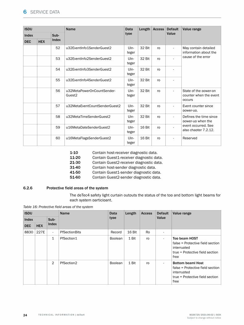
6.2.6 Protective field areas of the system
The deTec4 safety light curtain outputs the status of the top and bottom light beams foreach system participant.
Table 16: Protective field areas of the system
ISDU Name Datatype
Length Access DefaultValue
Value range
Index Sub-IndexDEC HEX
8830 227E - PfSectionBits Record 16 Bit Ro -
1 PfSection1 Boolean 1 Bit ro - Top beam HOSTfalse = Protective field sectioninterruptedtrue = Protective field sectionfree
2 PfSection2 Boolean 1 Bit ro - Bottom beaml Hostfalse = Protective field sectioninterruptedtrue = Protective field sectionfree
6 SERVICE DATA
24 T E C H N I C A L I N F O R M A T I O N | deTec4 8026725/2021-06-02 | SICKSubject to change without notice
ISDU Name Datatype
Length Access DefaultValue
Value range
Index Sub-IndexDEC HEX
3 PfSection3 Boolean 1 Bit ro - Top beam Guest1false = Protective field sectioninterruptedtrue = Protective field sectionfree
4 PfSection4 Boolean 1 Bit ro - Bottom beam Guest1false = Protective field sectioninterruptedtrue = Protective field sectionfree
5 PfSection5 Boolean 1 Bit ro - Top beam Guest2false = Protective field sectioninterruptedtrue = Protective field sectionfree
6 PfSection6 Boolean 1 Bit ro - Bottom beam Guest2false = Protective field sectioninterruptedtrue = Protective field sectionfree
7 PfSection7 Boolean 1 Bit ro - reserved
8 PfSection8 Boolean 1 Bit ro - reserved
9 PfSection9 Boolean 1 Bit ro - reserved
10 PfSection10 Boolean 1 Bit ro - reserved
11 PfSection11 Boolean 1 Bit ro - reserved
12 PfSection12 Boolean 1 Bit ro - reserved
13 PfSection13 Boolean 1 Bit ro - reserved
14 PfSection14 Boolean 1 Bit ro - reserved
15 PfSection15 Boolean 1 Bit ro - reserved
16 PfSection16 Boolean 1 Bit ro - reserved
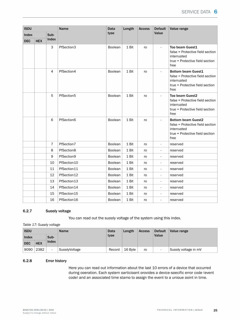
6.2.7 Supply voltage
You can read out the supply voltage of the system using this index.
Table 17: Supply voltage
ISDU Name Datatype
Length Access DefaultValue
Value range
Index Sub-IndexDEC HEX
9090 2382 - SupplyVoltage Record 16 Byte ro - Supply voltage in mV
6.2.8 Error history
Here you can read out information about the last 10 errors of a device that occurredduring operation. Each system participant provides a device-specific error code (eventcode) and an associated time stamp to assign the event to a unique point in time.
SERVICE DATA 6
8026725/2021-06-02 | SICK T E C H N I C A L I N F O R M A T I O N | deTec4 25Subject to change without notice
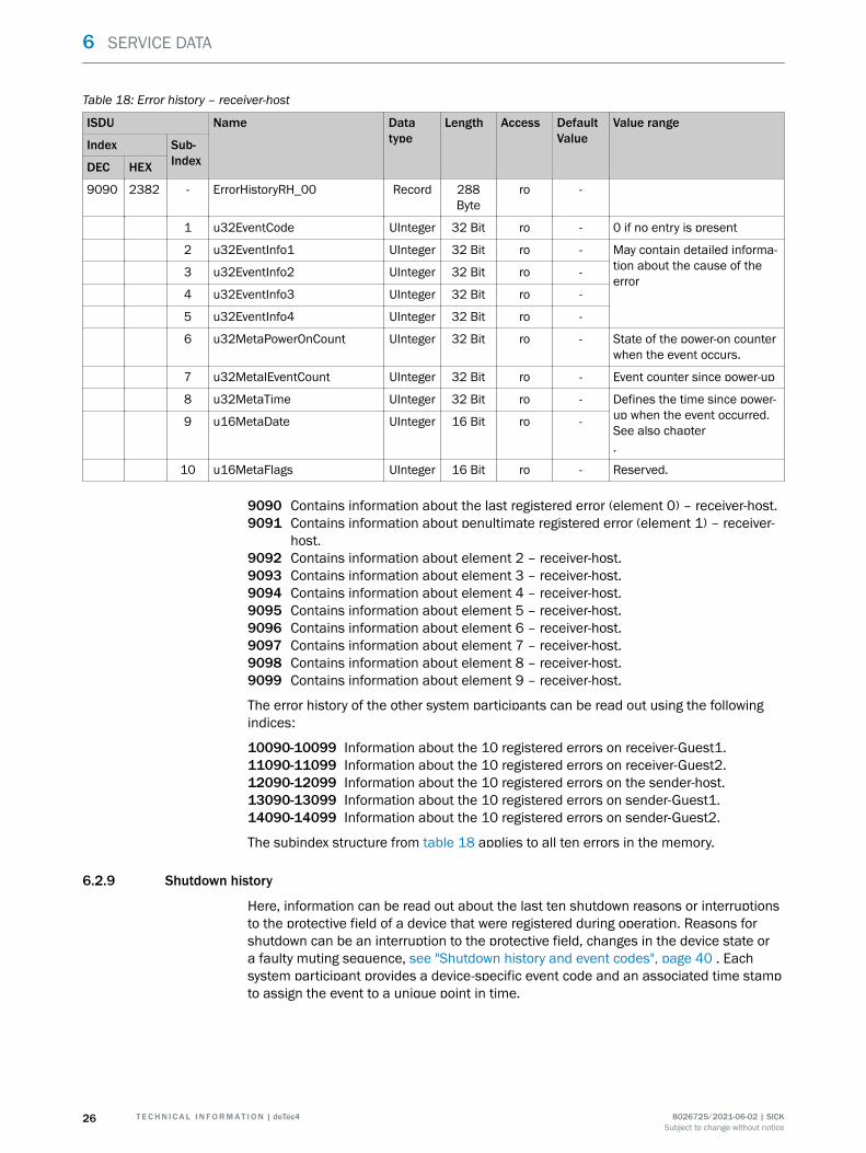
Table 18: Error history – receiver-host
ISDU Name Datatype
Length Access DefaultValue
Value range
Index Sub-IndexDEC HEX
9090 2382 - ErrorHistoryRH_00 Record 288Byte
ro -
1 u32EventCode UInteger 32 Bit ro - 0 if no entry is present
2 u32EventInfo1 UInteger 32 Bit ro - May contain detailed informa‐tion about the cause of theerror
3 u32EventInfo2 UInteger 32 Bit ro -
4 u32EventInfo3 UInteger 32 Bit ro -
5 u32EventInfo4 UInteger 32 Bit ro -
6 u32MetaPowerOnCount UInteger 32 Bit ro - State of the power-on counterwhen the event occurs.
7 u32MetalEventCount UInteger 32 Bit ro - Event counter since power-up
8 u32MetaTime UInteger 32 Bit ro - Defines the time since power-up when the event occurred.See also chapter.
9 u16MetaDate UInteger 16 Bit ro -
10 u16MetaFlags UInteger 16 Bit ro - Reserved.
9090 Contains information about the last registered error (element 0) – receiver-host.9091 Contains information about penultimate registered error (element 1) – receiver-
host.9092 Contains information about element 2 – receiver-host.9093 Contains information about element 3 – receiver-host.9094 Contains information about element 4 – receiver-host.9095 Contains information about element 5 – receiver-host.9096 Contains information about element 6 – receiver-host.9097 Contains information about element 7 – receiver-host.9098 Contains information about element 8 – receiver-host.9099 Contains information about element 9 – receiver-host.
The error history of the other system participants can be read out using the followingindices:
10090-10099 Information about the 10 registered errors on receiver-Guest1.11090-11099 Information about the 10 registered errors on receiver-Guest2.12090-12099 Information about the 10 registered errors on the sender-host.13090-13099 Information about the 10 registered errors on sender-Guest1.14090-14099 Information about the 10 registered errors on sender-Guest2.
The subindex structure from table 18 applies to all ten errors in the memory.
6.2.9 Shutdown history
Here, information can be read out about the last ten shutdown reasons or interruptionsto the protective field of a device that were registered during operation. Reasons forshutdown can be an interruption to the protective field, changes in the device state ora faulty muting sequence, see "Shutdown history and event codes", page 40 . Eachsystem participant provides a device-specific event code and an associated time stampto assign the event to a unique point in time.
6 SERVICE DATA
26 T E C H N I C A L I N F O R M A T I O N | deTec4 8026725/2021-06-02 | SICKSubject to change without notice
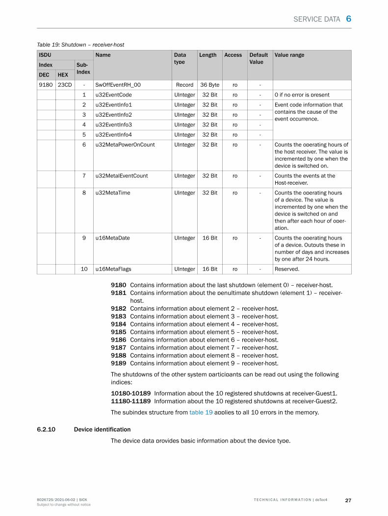
Table 19: Shutdown – receiver-host
ISDU Name Datatype
Length Access DefaultValue
Value range
Index Sub-IndexDEC HEX
9180 23CD - SwOffEventRH_00 Record 36 Byte ro -
1 u32EventCode UInteger 32 Bit ro - 0 if no error is present
2 u32EventInfo1 UInteger 32 Bit ro - Event code information thatcontains the cause of theevent occurrence.
3 u32EventInfo2 UInteger 32 Bit ro -
4 u32EventInfo3 UInteger 32 Bit ro -
5 u32EventInfo4 UInteger 32 Bit ro -
6 u32MetaPowerOnCount UInteger 32 Bit ro - Counts the operating hours ofthe host receiver. The value isincremented by one when thedevice is switched on.
7 u32MetalEventCount UInteger 32 Bit ro - Counts the events at theHost-receiver.
8 u32MetaTime UInteger 32 Bit ro - Counts the operating hoursof a device. The value isincremented by one when thedevice is switched on andthen after each hour of oper‐ation.
9 u16MetaDate UInteger 16 Bit ro - Counts the operating hoursof a device. Outputs these innumber of days and increasesby one after 24 hours.
10 u16MetaFlags UInteger 16 Bit ro - Reserved.
9180 Contains information about the last shutdown (element 0) – receiver-host.9181 Contains information about the penultimate shutdown (element 1) – receiver-
host.9182 Contains information about element 2 – receiver-host.9183 Contains information about element 3 – receiver-host.9184 Contains information about element 4 – receiver-host.9185 Contains information about element 5 – receiver-host.9186 Contains information about element 6 – receiver-host.9187 Contains information about element 7 – receiver-host.9188 Contains information about element 8 – receiver-host.9189 Contains information about element 9 – receiver-host.
The shutdowns of the other system participants can be read out using the followingindices:
10180-10189 Information about the 10 registered shutdowns at receiver-Guest1.11180-11189 Information about the 10 registered shutdowns at receiver-Guest2.
The subindex structure from table 19 applies to all 10 errors in the memory.
6.2.10 Device identification
The device data provides basic information about the device type.
SERVICE DATA 6
8026725/2021-06-02 | SICK T E C H N I C A L I N F O R M A T I O N | deTec4 27Subject to change without notice
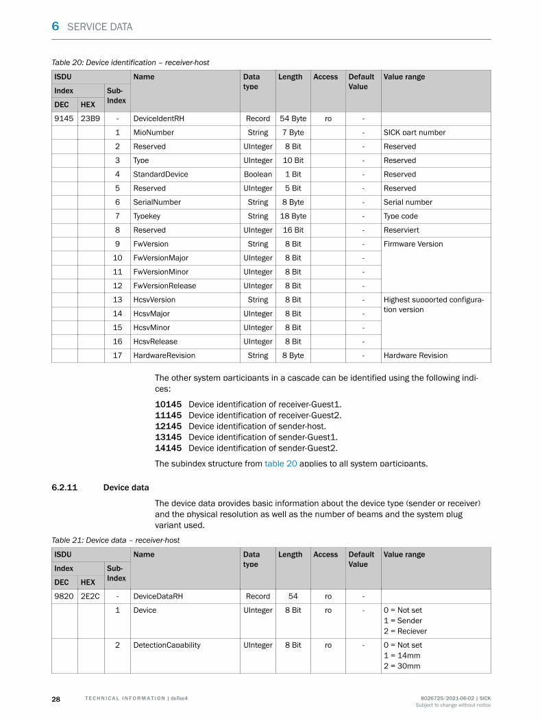
Table 20: Device identification – receiver-host
ISDU Name Datatype
Length Access DefaultValue
Value range
Index Sub-IndexDEC HEX
9145 23B9 - DeviceIdentRH Record 54 Byte ro -
1 MioNumber String 7 Byte - SICK part number
2 Reserved UInteger 8 Bit - Reserved
3 Type UInteger 10 Bit - Reserved
4 StandardDevice Boolean 1 Bit - Reserved
5 Reserved UInteger 5 Bit - Reserved
6 SerialNumber String 8 Byte - Serial number
7 Typekey String 18 Byte - Type code
8 Reserved UInteger 16 Bit - Reserviert
9 FwVersion String 8 Bit - Firmware Version
10 FwVersionMajor UInteger 8 Bit -
11 FwVersionMinor UInteger 8 Bit -
12 FwVersionRelease UInteger 8 Bit -
13 HcsvVersion String 8 Bit - Highest supported configura‐tion version14 HcsvMajor UInteger 8 Bit -
15 HcsvMinor UInteger 8 Bit -
16 HcsvRelease UInteger 8 Bit -
17 HardwareRevision String 8 Byte - Hardware Revision
The other system participants in a cascade can be identified using the following indi‐ces:
10145 Device identification of receiver-Guest1.11145 Device identification of receiver-Guest2.12145 Device identification of sender-host.13145 Device identification of sender-Guest1.14145 Device identification of sender-Guest2.
The subindex structure from table 20 applies to all system participants.
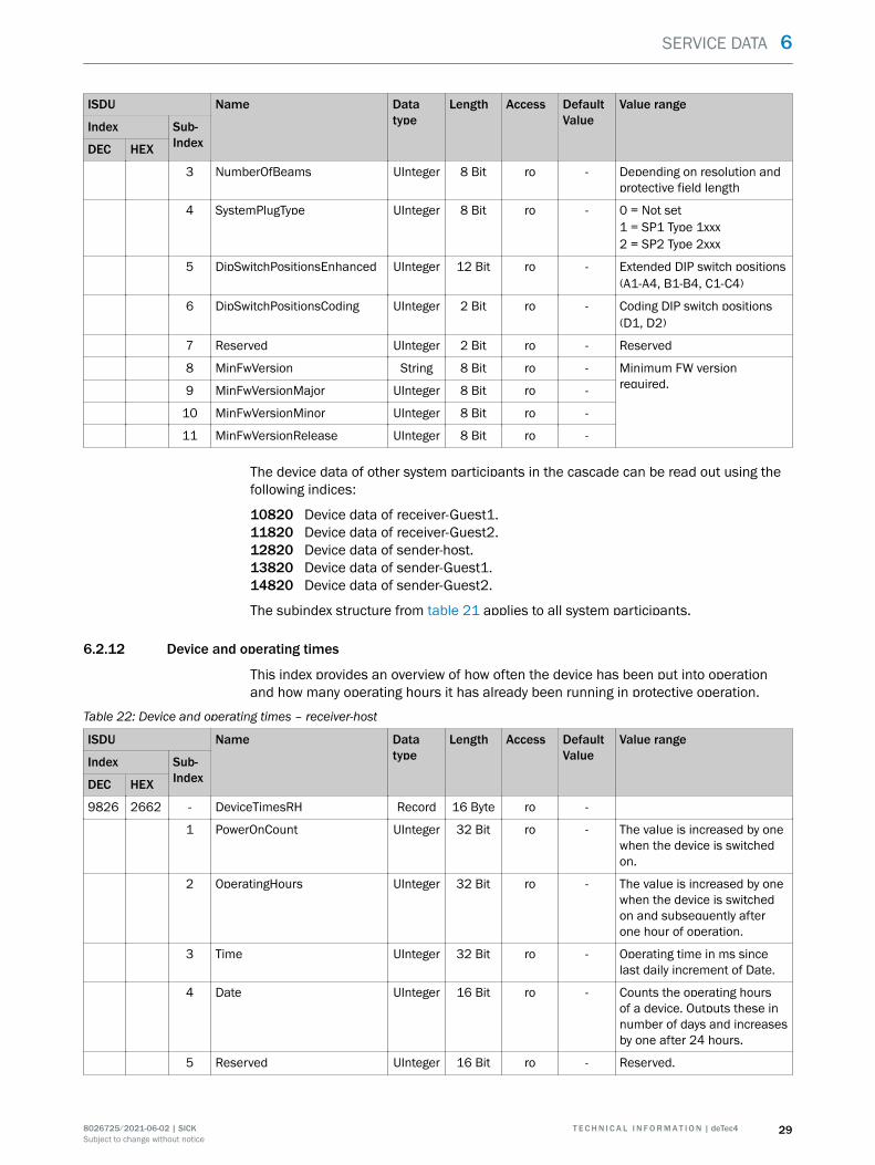
6.2.11 Device data
The device data provides basic information about the device type (sender or receiver)and the physical resolution as well as the number of beams and the system plugvariant used.
Table 21: Device data – receiver-host
ISDU Name Datatype
Length Access DefaultValue
Value range
Index Sub-IndexDEC HEX
9820 2E2C - DeviceDataRH Record 54 ro -
1 Device UInteger 8 Bit ro - 0 = Not set1 = Sender2 = Reciever
2 DetectionCapability UInteger 8 Bit ro - 0 = Not set1 = 14mm2 = 30mm
6 SERVICE DATA
28 T E C H N I C A L I N F O R M A T I O N | deTec4 8026725/2021-06-02 | SICKSubject to change without notice
ISDU Name Datatype
Length Access DefaultValue
Value range
Index Sub-IndexDEC HEX
3 NumberOfBeams UInteger 8 Bit ro - Depending on resolution andprotective field length
4 SystemPlugType UInteger 8 Bit ro - 0 = Not set1 = SP1 Type 1xxx2 = SP2 Type 2xxx
5 DipSwitchPositionsEnhanced UInteger 12 Bit ro - Extended DIP switch positions(A1-A4, B1-B4, C1-C4)
6 DipSwitchPositionsCoding UInteger 2 Bit ro - Coding DIP switch positions(D1, D2)
7 Reserved UInteger 2 Bit ro - Reserved
8 MinFwVersion String 8 Bit ro - Minimum FW versionrequired.9 MinFwVersionMajor UInteger 8 Bit ro -
10 MinFwVersionMinor UInteger 8 Bit ro -
11 MinFwVersionRelease UInteger 8 Bit ro -
The device data of other system participants in the cascade can be read out using thefollowing indices:
10820 Device data of receiver-Guest1.11820 Device data of receiver-Guest2.12820 Device data of sender-host.13820 Device data of sender-Guest1.14820 Device data of sender-Guest2.
The subindex structure from table 21 applies to all system participants.
6.2.12 Device and operating times
This index provides an overview of how often the device has been put into operationand how many operating hours it has already been running in protective operation.
Table 22: Device and operating times – receiver-host
ISDU Name Datatype
Length Access DefaultValue
Value range
Index Sub-IndexDEC HEX
9826 2662 - DeviceTimesRH Record 16 Byte ro -
1 PowerOnCount UInteger 32 Bit ro - The value is increased by onewhen the device is switchedon.
2 OperatingHours UInteger 32 Bit ro - The value is increased by onewhen the device is switchedon and subsequently afterone hour of operation.
3 Time UInteger 32 Bit ro - Operating time in ms sincelast daily increment of Date.
4 Date UInteger 16 Bit ro - Counts the operating hoursof a device. Outputs these innumber of days and increasesby one after 24 hours.
5 Reserved UInteger 16 Bit ro - Reserved.
SERVICE DATA 6
8026725/2021-06-02 | SICK T E C H N I C A L I N F O R M A T I O N | deTec4 29Subject to change without notice
The device or operating times of other system participants in the cascade can be readout using the following indices:
10826 Device or operating data of receiver-Guest1.11826 Device or operating data of receiver-Guest2.12826 Device or operating data of sender-host.13826 Device or operating data of sender-Guest1.14826 Device or operating data of sender-Guest2.
The subindex structure from table 22 applies to all system participants.
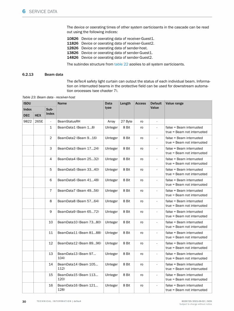
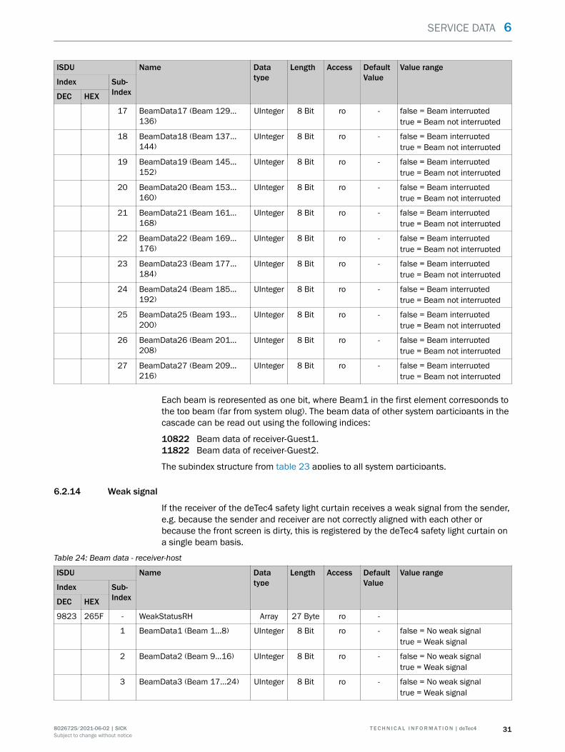
6.2.13 Beam data
The deTec4 safety light curtain can output the status of each individual beam. Informa‐tion on interrupted beams in the protective field can be used for downstream automa‐tion processes (see chapter 7).
Table 23: Beam data - receiver-host
ISDU Name Datatype
Length Access DefaultValue
Value range
Index Sub-IndexDEC HEX
9822 265E - BeamStatusRH Array 27 Byte ro -
1 BeamData1 (Beam 1…8) UInteger 8 Bit ro - false = Beam interruptedtrue = Beam not interrupted
2 BeamData2 (Beam 9…16) UInteger 8 Bit ro - false = Beam interruptedtrue = Beam not interrupted
3 BeamData3 (Beam 17…24) UInteger 8 Bit ro - false = Beam interruptedtrue = Beam not interrupted
4 BeamData4 (Beam 25…32) UInteger 8 Bit ro - false = Beam interruptedtrue = Beam not interrupted
5 BeamData5 (Beam 33…40) UInteger 8 Bit ro - false = Beam interruptedtrue = Beam not interrupted
6 BeamData6 (Beam 41…48) UInteger 8 Bit ro - false = Beam interruptedtrue = Beam not interrupted
7 BeamData7 (Beam 49…56) UInteger 8 Bit ro - false = Beam interruptedtrue = Beam not interrupted
8 BeamData8 (Beam 57…64) UInteger 8 Bit ro - false = Beam interruptedtrue = Beam not interrupted
9 BeamData9 (Beam 65…72) UInteger 8 Bit ro - false = Beam interruptedtrue = Beam not interrupted
10 BeamData10 (Beam 73…80) UInteger 8 Bit ro - false = Beam interruptedtrue = Beam not interrupted
11 BeamData11 (Beam 81…88) UInteger 8 Bit ro - false = Beam interruptedtrue = Beam not interrupted
12 BeamData12 (Beam 89…96) UInteger 8 Bit ro - false = Beam interruptedtrue = Beam not interrupted
13 BeamData13 (Beam 97…104)
UInteger 8 Bit ro - false = Beam interruptedtrue = Beam not interrupted
14 BeamData14 (Beam 105…112)
UInteger 8 Bit ro - false = Beam interruptedtrue = Beam not interrupted
15 BeamData15 (Beam 113…120)
UInteger 8 Bit ro - false = Beam interruptedtrue = Beam not interrupted
16 BeamData16 (Beam 121…128)
UInteger 8 Bit ro - false = Beam interruptedtrue = Beam not interrupted
6 SERVICE DATA
30 T E C H N I C A L I N F O R M A T I O N | deTec4 8026725/2021-06-02 | SICKSubject to change without notice
ISDU Name Datatype
Length Access DefaultValue
Value range
Index Sub-IndexDEC HEX
17 BeamData17 (Beam 129…136)
UInteger 8 Bit ro - false = Beam interruptedtrue = Beam not interrupted
18 BeamData18 (Beam 137…144)
UInteger 8 Bit ro - false = Beam interruptedtrue = Beam not interrupted
19 BeamData19 (Beam 145…152)
UInteger 8 Bit ro - false = Beam interruptedtrue = Beam not interrupted
20 BeamData20 (Beam 153…160)
UInteger 8 Bit ro - false = Beam interruptedtrue = Beam not interrupted
21 BeamData21 (Beam 161…168)
UInteger 8 Bit ro - false = Beam interruptedtrue = Beam not interrupted
22 BeamData22 (Beam 169…176)
UInteger 8 Bit ro - false = Beam interruptedtrue = Beam not interrupted
23 BeamData23 (Beam 177…184)
UInteger 8 Bit ro - false = Beam interruptedtrue = Beam not interrupted
24 BeamData24 (Beam 185…192)
UInteger 8 Bit ro - false = Beam interruptedtrue = Beam not interrupted
25 BeamData25 (Beam 193…200)
UInteger 8 Bit ro - false = Beam interruptedtrue = Beam not interrupted
26 BeamData26 (Beam 201…208)
UInteger 8 Bit ro - false = Beam interruptedtrue = Beam not interrupted
27 BeamData27 (Beam 209…216)
UInteger 8 Bit ro - false = Beam interruptedtrue = Beam not interrupted
Each beam is represented as one bit, where Beam1 in the first element corresponds tothe top beam (far from system plug). The beam data of other system participants in thecascade can be read out using the following indices:
10822 Beam data of receiver-Guest1.11822 Beam data of receiver-Guest2.
The subindex structure from table 23 applies to all system participants.
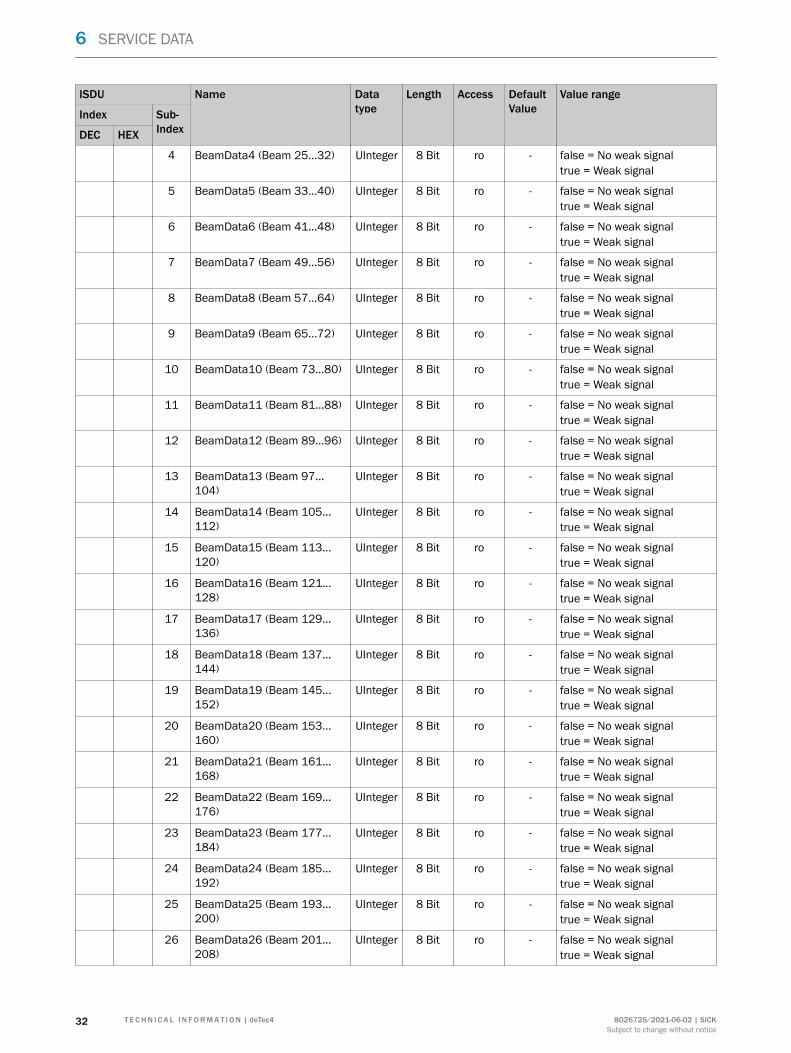
6.2.14 Weak signal
If the receiver of the deTec4 safety light curtain receives a weak signal from the sender,e.g. because the sender and receiver are not correctly aligned with each other orbecause the front screen is dirty, this is registered by the deTec4 safety light curtain ona single beam basis.
Table 24: Beam data - receiver-host
ISDU Name Datatype
Length Access DefaultValue
Value range
Index Sub-IndexDEC HEX
9823 265F - WeakStatusRH Array 27 Byte ro -
1 BeamData1 (Beam 1…8) UInteger 8 Bit ro - false = No weak signaltrue = Weak signal
2 BeamData2 (Beam 9…16) UInteger 8 Bit ro - false = No weak signaltrue = Weak signal
3 BeamData3 (Beam 17…24) UInteger 8 Bit ro - false = No weak signaltrue = Weak signal
SERVICE DATA 6
8026725/2021-06-02 | SICK T E C H N I C A L I N F O R M A T I O N | deTec4 31Subject to change without notice
ISDU Name Datatype
Length Access DefaultValue
Value range
Index Sub-IndexDEC HEX
4 BeamData4 (Beam 25…32) UInteger 8 Bit ro - false = No weak signaltrue = Weak signal
5 BeamData5 (Beam 33…40) UInteger 8 Bit ro - false = No weak signaltrue = Weak signal
6 BeamData6 (Beam 41…48) UInteger 8 Bit ro - false = No weak signaltrue = Weak signal
7 BeamData7 (Beam 49…56) UInteger 8 Bit ro - false = No weak signaltrue = Weak signal
8 BeamData8 (Beam 57…64) UInteger 8 Bit ro - false = No weak signaltrue = Weak signal
9 BeamData9 (Beam 65…72) UInteger 8 Bit ro - false = No weak signaltrue = Weak signal
10 BeamData10 (Beam 73…80) UInteger 8 Bit ro - false = No weak signaltrue = Weak signal
11 BeamData11 (Beam 81…88) UInteger 8 Bit ro - false = No weak signaltrue = Weak signal
12 BeamData12 (Beam 89…96) UInteger 8 Bit ro - false = No weak signaltrue = Weak signal
13 BeamData13 (Beam 97…104)
UInteger 8 Bit ro - false = No weak signaltrue = Weak signal
14 BeamData14 (Beam 105…112)
UInteger 8 Bit ro - false = No weak signaltrue = Weak signal
15 BeamData15 (Beam 113…120)
UInteger 8 Bit ro - false = No weak signaltrue = Weak signal
16 BeamData16 (Beam 121…128)
UInteger 8 Bit ro - false = No weak signaltrue = Weak signal
17 BeamData17 (Beam 129…136)
UInteger 8 Bit ro - false = No weak signaltrue = Weak signal
18 BeamData18 (Beam 137…144)
UInteger 8 Bit ro - false = No weak signaltrue = Weak signal
19 BeamData19 (Beam 145…152)
UInteger 8 Bit ro - false = No weak signaltrue = Weak signal
20 BeamData20 (Beam 153…160)
UInteger 8 Bit ro - false = No weak signaltrue = Weak signal
21 BeamData21 (Beam 161…168)
UInteger 8 Bit ro - false = No weak signaltrue = Weak signal
22 BeamData22 (Beam 169…176)
UInteger 8 Bit ro - false = No weak signaltrue = Weak signal
23 BeamData23 (Beam 177…184)
UInteger 8 Bit ro - false = No weak signaltrue = Weak signal
24 BeamData24 (Beam 185…192)
UInteger 8 Bit ro - false = No weak signaltrue = Weak signal
25 BeamData25 (Beam 193…200)
UInteger 8 Bit ro - false = No weak signaltrue = Weak signal
26 BeamData26 (Beam 201…208)
UInteger 8 Bit ro - false = No weak signaltrue = Weak signal
6 SERVICE DATA
32 T E C H N I C A L I N F O R M A T I O N | deTec4 8026725/2021-06-02 | SICKSubject to change without notice
ISDU Name Datatype
Length Access DefaultValue
Value range
Index Sub-IndexDEC HEX
27 BeamData27 (Beam 209…216)
UInteger 8 Bit ro - false = No weak signaltrue = Weak signal
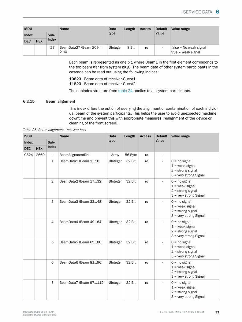
Each beam is represented as one bit, where Beam1 in the first element corresponds tothe top beam (far from system plug). The beam data of other system participants in thecascade can be read out using the following indices:
10823 Beam data of receiver-Guest1.11823 Beam data of receiver-Guest2.
The subindex structure from table 24 applies to all system participants.
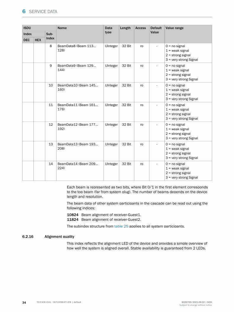
6.2.15 Beam alignment
This index offers the option of querying the alignment or contamination of each individ‐ual beam of the system participants. This helps the user to avoid unexpected machinedowntime and prevent this with appropriate measures (realignment of the device orcleaning of the front screen).
Table 25: Beam alignment - receiver-host
ISDU Name Datatype
Length Access DefaultValue
Value range
Index Sub-IndexDEC HEX
9824 2660 - BeamAlignmentRH Array 56 Byte ro -
1 BeamData1 (Beam 1…16) UInteger 32 Bit ro - 0 = no signal1 = weak signal2 = strong signal3 = very strong Signal
2 BeamData2 (Beam 17…32) UInteger 32 Bit ro - 0 = no signal1 = weak signal2 = strong signal3 = very strong Signal
3 BeamData3 (Beam 33…48) UInteger 32 Bit ro - 0 = no signal1 = weak signal2 = strong signal3 = very strong Signal
4 BeamData4 (Beam 49…64) UInteger 32 Bit ro - 0 = no signal1 = weak signal2 = strong signal3 = very strong Signal
5 BeamData5 (Beam 65…80) UInteger 32 Bit ro - 0 = no signal1 = weak signal2 = strong signal3 = very strong Signal
6 BeamData6 (Beam 81…96) UInteger 32 Bit ro - 0 = no signal1 = weak signal2 = strong signal3 = very strong Signal
7 BeamData7 (Beam 97…112) UInteger 32 Bit ro - 0 = no signal1 = weak signal2 = strong signal3 = very strong Signal
SERVICE DATA 6
8026725/2021-06-02 | SICK T E C H N I C A L I N F O R M A T I O N | deTec4 33Subject to change without notice
ISDU Name Datatype
Length Access DefaultValue
Value range
Index Sub-IndexDEC HEX
8 BeamData8 (Beam 113…128)
UInteger 32 Bit ro - 0 = no signal1 = weak signal2 = strong signal3 = very strong Signal
9 BeamData9 (Beam 129…144)
UInteger 32 Bit ro - 0 = no signal1 = weak signal2 = strong signal3 = very strong Signal
10 BeamData10 (Beam 145…160)
UInteger 32 Bit ro - 0 = no signal1 = weak signal2 = strong signal3 = very strong Signal
11 BeamData11 (Beam 161…176)
UInteger 32 Bit ro - 0 = no signal1 = weak signal2 = strong signal3 = very strong Signal
12 BeamData12 (Beam 177…192)
UInteger 32 Bit ro - 0 = no signal1 = weak signal2 = strong signal3 = very strong Signal
13 BeamData13 (Beam 193…208)
UInteger 32 Bit ro - 0 = no signal1 = weak signal2 = strong signal3 = very strong Signal
14 BeamData14 (Beam 209…224)
UInteger 32 Bit ro - 0 = no signal1 = weak signal2 = strong signal3 = very strong Signal
Each beam is represented as two bits, where Bit 0/1 in the first element correspondsto the top beam (far from system plug). The number of beams depends on the devicelength and resolution.
The beam data of other system participants in the cascade can be read out using thefollowing indices:
10824 Beam alignment of receiver-Guest1.11824 Beam alignment of receiver-Guest2.
The subindex structure from table 25 applies to all system participants.
6.2.16 Alignment quality
This index reflects the alignment LED of the device and provides a simple overview ofhow well the system is aligned overall. Stable availability is guaranteed from 2 LEDs.
6 SERVICE DATA
34 T E C H N I C A L I N F O R M A T I O N | deTec4 8026725/2021-06-02 | SICKSubject to change without notice
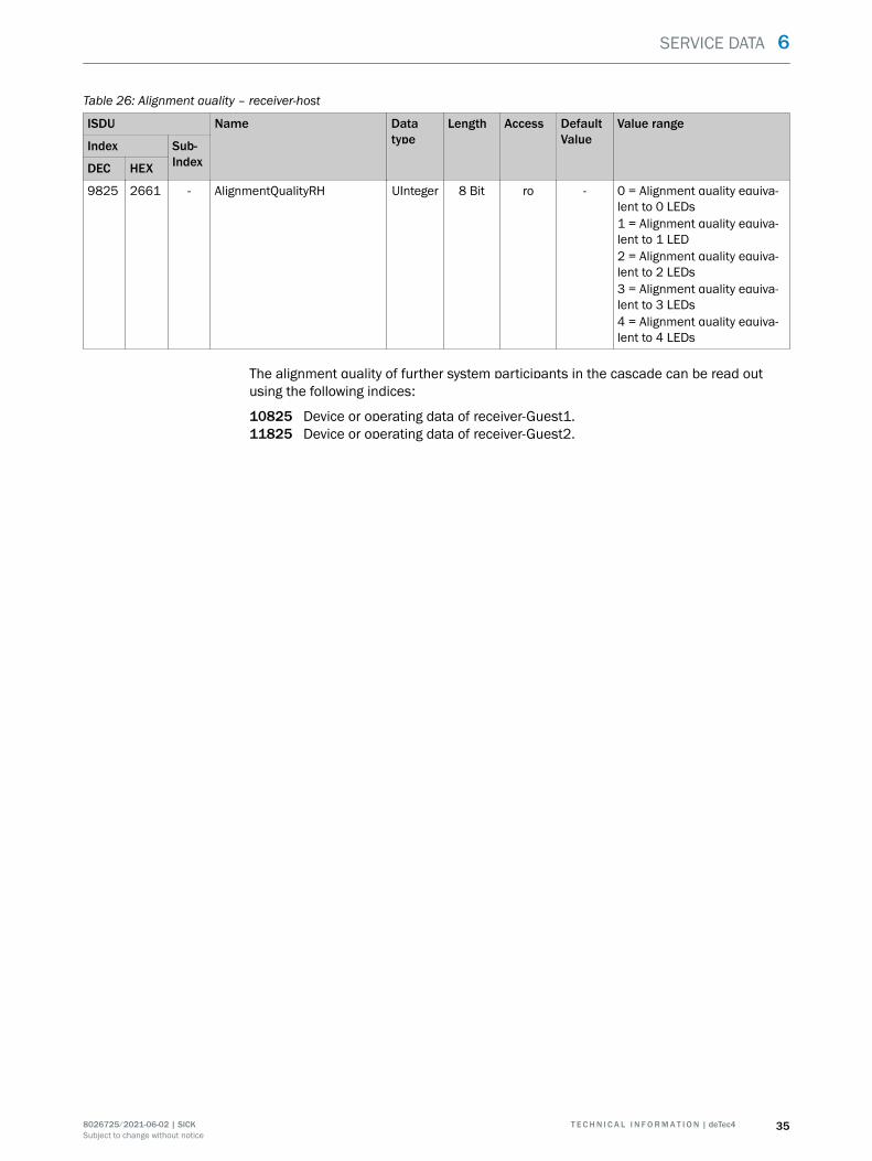
Table 26: Alignment quality – receiver-host
ISDU Name Datatype
Length Access DefaultValue
Value range
Index Sub-IndexDEC HEX
9825 2661 - AlignmentQualityRH UInteger 8 Bit ro - 0 = Alignment quality equiva‐lent to 0 LEDs1 = Alignment quality equiva‐lent to 1 LED2 = Alignment quality equiva‐lent to 2 LEDs3 = Alignment quality equiva‐lent to 3 LEDs4 = Alignment quality equiva‐lent to 4 LEDs
The alignment quality of further system participants in the cascade can be read outusing the following indices:
10825 Device or operating data of receiver-Guest1.11825 Device or operating data of receiver-Guest2.
SERVICE DATA 6
8026725/2021-06-02 | SICK T E C H N I C A L I N F O R M A T I O N | deTec4 35Subject to change without notice
7 Example applications
This chapter provides information about a few selected application examples to illus‐trate the use of the provided IO-Link data of the deTec4 safety light curtain.
7.1 Alignment and contamination
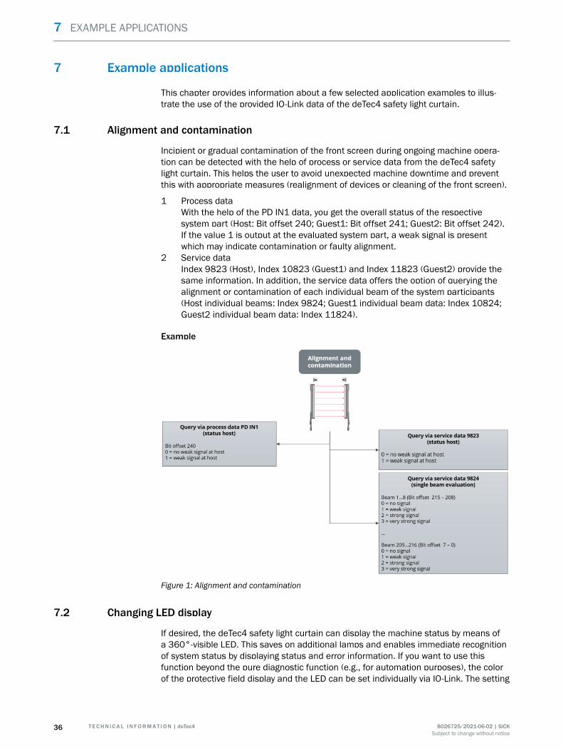
Incipient or gradual contamination of the front screen during ongoing machine opera‐tion can be detected with the help of process or service data from the deTec4 safetylight curtain. This helps the user to avoid unexpected machine downtime and preventthis with appropriate measures (realignment of devices or cleaning of the front screen).
1 Process dataWith the help of the PD IN1 data, you get the overall status of the respectivesystem part (Host: Bit offset 240; Guest1: Bit offset 241; Guest2: Bit offset 242).If the value 1 is output at the evaluated system part, a weak signal is presentwhich may indicate contamination or faulty alignment.
2 Service dataIndex 9823 (Host), Index 10823 (Guest1) and Index 11823 (Guest2) provide thesame information. In addition, the service data offers the option of querying thealignment or contamination of each individual beam of the system participants(Host individual beams: Index 9824; Guest1 individual beam data: Index 10824;Guest2 individual beam data: Index 11824).
Example
Figure 1: Alignment and contamination
7.2 Changing LED display
If desired, the deTec4 safety light curtain can display the machine status by means ofa 360°-visible LED. This saves on additional lamps and enables immediate recognitionof system status by displaying status and error information. If you want to use thisfunction beyond the pure diagnostic function (e.g., for automation purposes), the colorof the protective field display and the LED can be set individually via IO-Link. The setting
7 EXAMPLE APPLICATIONS
36 T E C H N I C A L I N F O R M A T I O N | deTec4 8026725/2021-06-02 | SICKSubject to change without notice
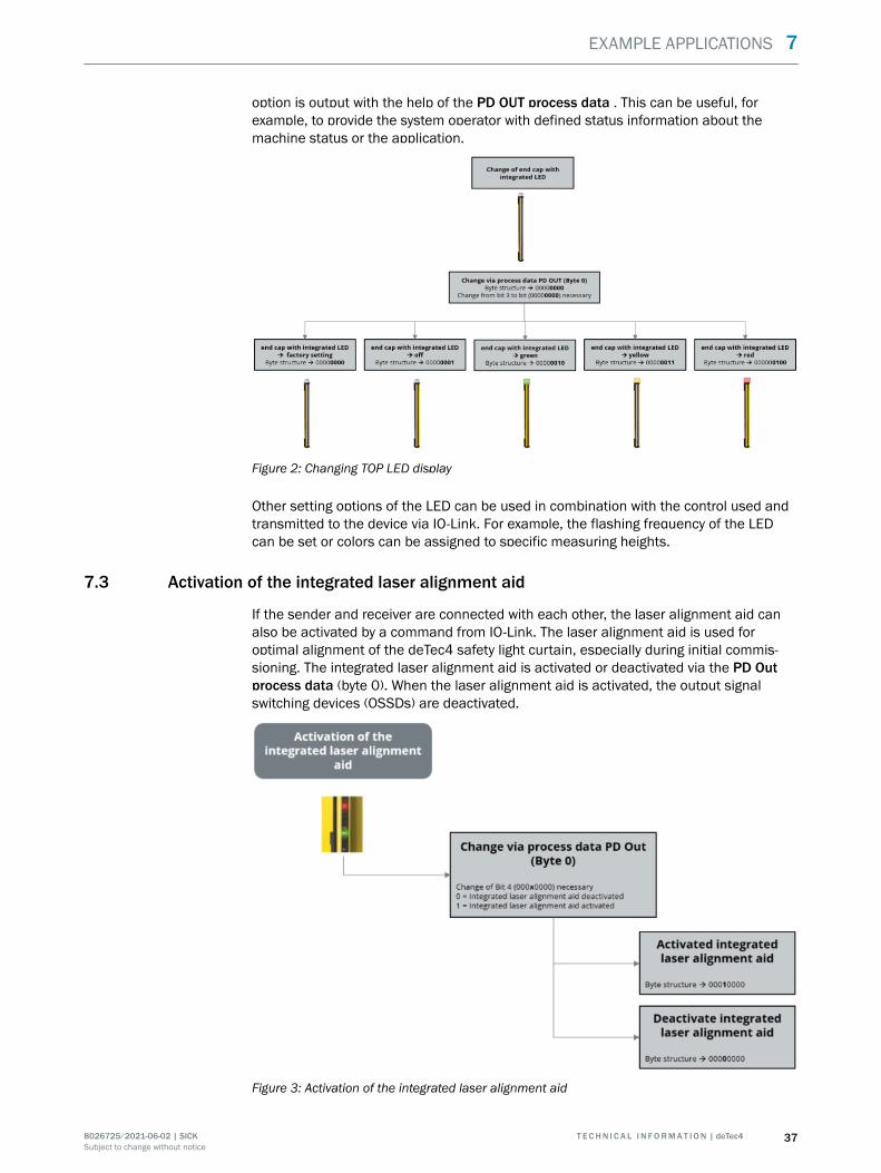
option is output with the help of the PD OUT process data . This can be useful, forexample, to provide the system operator with defined status information about themachine status or the application.
Figure 2: Changing TOP LED display
Other setting options of the LED can be used in combination with the control used andtransmitted to the device via IO-Link. For example, the flashing frequency of the LEDcan be set or colors can be assigned to specific measuring heights.
7.3 Activation of the integrated laser alignment aid
If the sender and receiver are connected with each other, the laser alignment aid canalso be activated by a command from IO-Link. The laser alignment aid is used foroptimal alignment of the deTec4 safety light curtain, especially during initial commis‐sioning. The integrated laser alignment aid is activated or deactivated via the PD Outprocess data (byte 0). When the laser alignment aid is activated, the output signalswitching devices (OSSDs) are deactivated.
Figure 3: Activation of the integrated laser alignment aid
EXAMPLE APPLICATIONS 7
8026725/2021-06-02 | SICK T E C H N I C A L I N F O R M A T I O N | deTec4 37Subject to change without notice
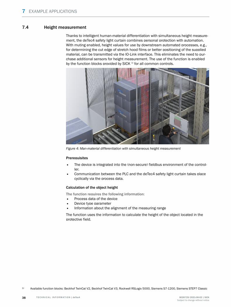
7.4 Height measurement
Thanks to intelligent human-material differentiation with simultaneous height measure‐ment, the deTec4 safety light curtain combines personal protection with automation.With muting enabled, height values for use by downstream automated processes, e.g.,for determining the cut edge of stretch hood films or better positioning of the suppliedmaterial, can be transmitted via the IO-Link interface. This eliminates the need to pur‐chase additional sensors for height measurement. The use of the function is enabledby the function blocks provided by SICK 1) for all common controls.
Figure 4: Man-material differentiation with simultaneous height measurement
Prerequisites
• The device is integrated into the (non-secure) fieldbus environment of the control‐ler.
• Communication between the PLC and the deTec4 safety light curtain takes placecyclically via the process data.
Calculation of the object height
The function requires the following information:• Process data of the device• Device type parameter• Information about the alignment of the measuring range
The function uses the information to calculate the height of the object located in theprotective field.
1) Available function blocks: Beckhof TwinCat V2, Beckhof TwinCat V3, Rockwell RSLogix 5000, Siemens S7-1200, Siemens STEP7 Classic
7 EXAMPLE APPLICATIONS
38 T E C H N I C A L I N F O R M A T I O N | deTec4 8026725/2021-06-02 | SICKSubject to change without notice
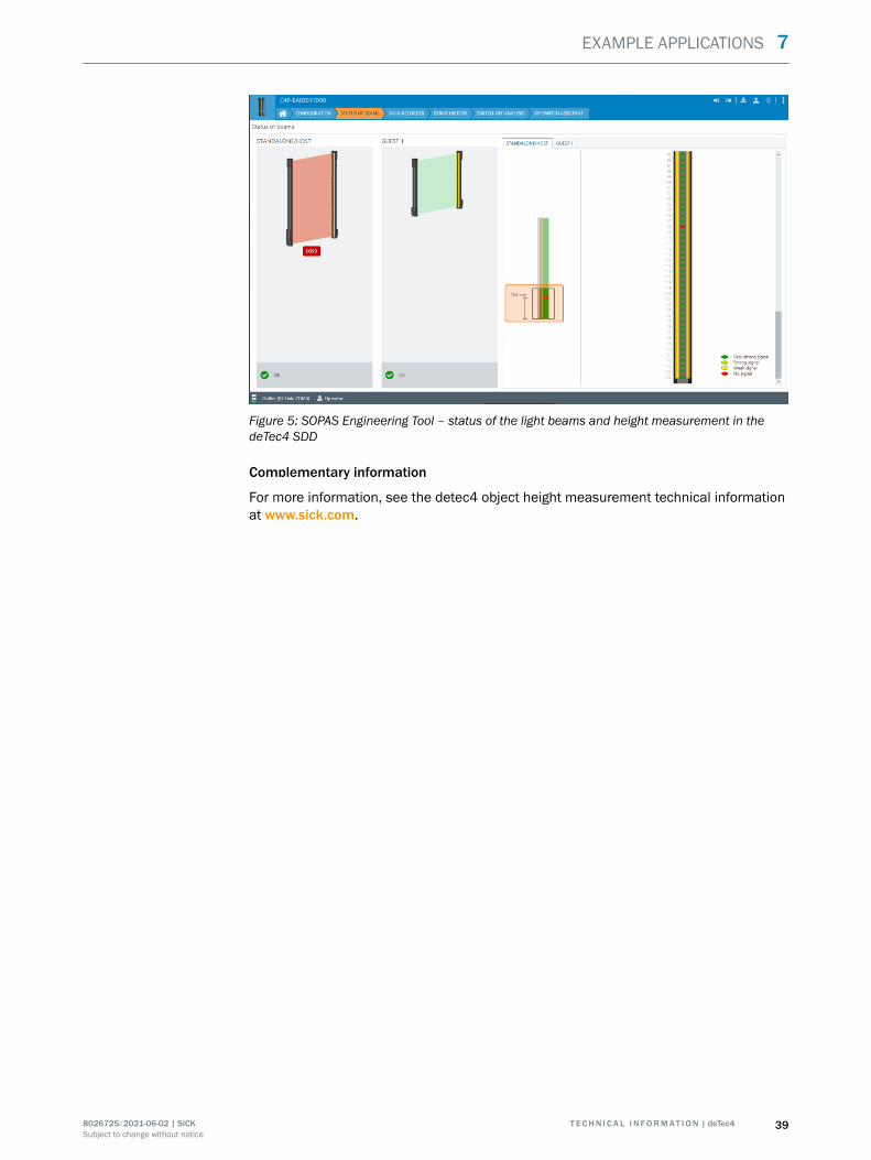
Figure 5: SOPAS Engineering Tool – status of the light beams and height measurement in thedeTec4 SDD
Complementary information
For more information, see the detec4 object height measurement technical informationat www.sick.com.
EXAMPLE APPLICATIONS 7
8026725/2021-06-02 | SICK T E C H N I C A L I N F O R M A T I O N | deTec4 39Subject to change without notice
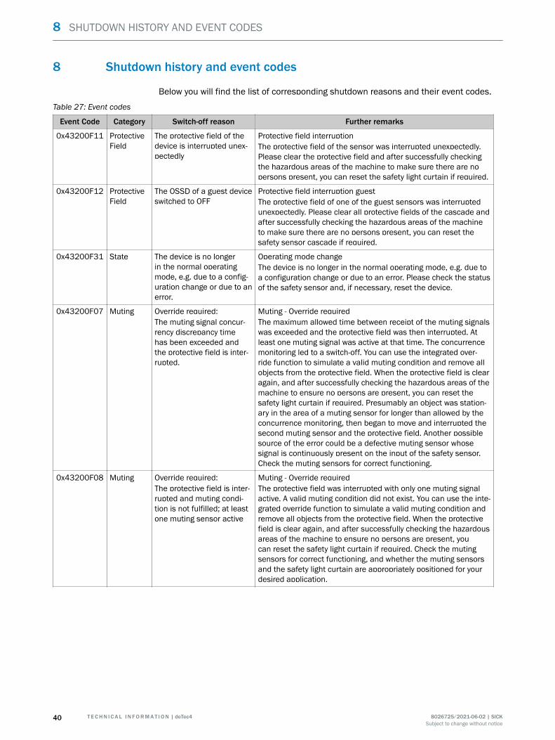
8 Shutdown history and event codes
Below you will find the list of corresponding shutdown reasons and their event codes.
Table 27: Event codes
Event Code Category Switch-off reason Further remarks
0x43200F11 ProtectiveField
The protective field of thedevice is interrupted unex‐pectedly
Protective field interruptionThe protective field of the sensor was interrupted unexpectedly.Please clear the protective field and after successfully checkingthe hazardous areas of the machine to make sure there are nopersons present, you can reset the safety light curtain if required.
0x43200F12 ProtectiveField
The OSSD of a guest deviceswitched to OFF
Protective field interruption guestThe protective field of one of the guest sensors was interruptedunexpectedly. Please clear all protective fields of the cascade andafter successfully checking the hazardous areas of the machineto make sure there are no persons present, you can reset thesafety sensor cascade if required.
0x43200F31 State The device is no longerin the normal operatingmode, e.g. due to a config‐uration change or due to anerror.
Operating mode changeThe device is no longer in the normal operating mode, e.g. due toa configuration change or due to an error. Please check the statusof the safety sensor and, if necessary, reset the device.
0x43200F07 Muting Override required:The muting signal concur‐rency discrepancy timehas been exceeded andthe protective field is inter‐rupted.
Muting - Override requiredThe maximum allowed time between receipt of the muting signalswas exceeded and the protective field was then interrupted. Atleast one muting signal was active at that time. The concurrencemonitoring led to a switch-off. You can use the integrated over‐ride function to simulate a valid muting condition and remove allobjects from the protective field. When the protective field is clearagain, and after successfully checking the hazardous areas of themachine to ensure no persons are present, you can reset thesafety light curtain if required. Presumably an object was station‐ary in the area of a muting sensor for longer than allowed by theconcurrence monitoring, then began to move and interrupted thesecond muting sensor and the protective field. Another possiblesource of the error could be a defective muting sensor whosesignal is continuously present on the input of the safety sensor.Check the muting sensors for correct functioning.
0x43200F08 Muting Override required:The protective field is inter‐rupted and muting condi‐tion is not fulfilled; at leastone muting sensor active
Muting - Override requiredThe protective field was interrupted with only one muting signalactive. A valid muting condition did not exist. You can use the inte‐grated override function to simulate a valid muting condition andremove all objects from the protective field. When the protectivefield is clear again, and after successfully checking the hazardousareas of the machine to ensure no persons are present, youcan reset the safety light curtain if required. Check the mutingsensors for correct functioning, and whether the muting sensorsand the safety light curtain are appropriately positioned for yourdesired application.
8 SHUTDOWN HISTORY AND EVENT CODES
40 T E C H N I C A L I N F O R M A T I O N | deTec4 8026725/2021-06-02 | SICKSubject to change without notice
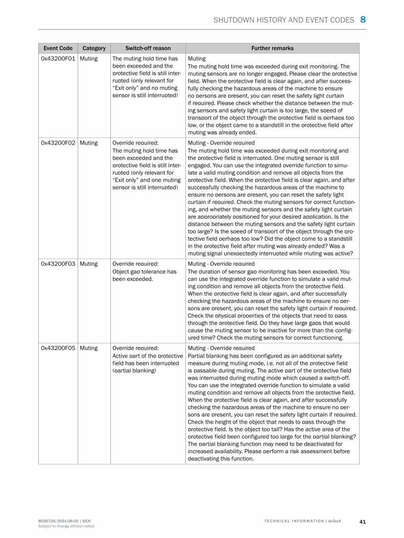
Event Code Category Switch-off reason Further remarks
0x43200F01 Muting The muting hold time hasbeen exceeded and theprotective field is still inter‐rupted (only relevant for“Exit only” and no mutingsensor is still interrupted)
MutingThe muting hold time was exceeded during exit monitoring. Themuting sensors are no longer engaged. Please clear the protectivefield. When the protective field is clear again, and after success‐fully checking the hazardous areas of the machine to ensureno persons are present, you can reset the safety light curtainif required. Please check whether the distance between the mut‐ing sensors and safety light curtain is too large, the speed oftransport of the object through the protective field is perhaps toolow, or the object came to a standstill in the protective field aftermuting was already ended.
0x43200F02 Muting Override required:The muting hold time hasbeen exceeded and theprotective field is still inter‐rupted (only relevant for“Exit only” and one mutingsensor is still interrupted)
Muting - Override requiredThe muting hold time was exceeded during exit monitoring andthe protective field is interrupted. One muting sensor is stillengaged. You can use the integrated override function to simu‐late a valid muting condition and remove all objects from theprotective field. When the protective field is clear again, and aftersuccessfully checking the hazardous areas of the machine toensure no persons are present, you can reset the safety lightcurtain if required. Check the muting sensors for correct function‐ing, and whether the muting sensors and the safety light curtainare appropriately positioned for your desired application. Is thedistance between the muting sensors and the safety light curtaintoo large? Is the speed of transport of the object through the pro‐tective field perhaps too low? Did the object come to a standstillin the protective field after muting was already ended? Was amuting signal unexpectedly interrupted while muting was active?
0x43200F03 Muting Override required:Object gap tolerance hasbeen exceeded.
Muting - Override requiredThe duration of sensor gap monitoring has been exceeded. Youcan use the integrated override function to simulate a valid mut‐ing condition and remove all objects from the protective field.When the protective field is clear again, and after successfullychecking the hazardous areas of the machine to ensure no per‐sons are present, you can reset the safety light curtain if required.Check the physical properties of the objects that need to passthrough the protective field. Do they have large gaps that wouldcause the muting sensor to be inactive for more than the config‐ured time? Check the muting sensors for correct functioning.
0x43200F05 Muting Override required:Active part of the protectivefield has been interrupted(partial blanking)
Muting - Override requiredPartial blanking has been configured as an additional safetymeasure during muting mode, i.e. not all of the protective fieldis passable during muting. The active part of the protective fieldwas interrupted during muting mode which caused a switch-off.You can use the integrated override function to simulate a validmuting condition and remove all objects from the protective field.When the protective field is clear again, and after successfullychecking the hazardous areas of the machine to ensure no per‐sons are present, you can reset the safety light curtain if required.Check the height of the object that needs to pass through theprotective field. Is the object too tall? Has the active area of theprotective field been configured too large for the partial blanking?The partial blanking function may need to be deactivated forincreased availability. Please perform a risk assessment beforedeactivating this function.
SHUTDOWN HISTORY AND EVENT CODES 8
8026725/2021-06-02 | SICK T E C H N I C A L I N F O R M A T I O N | deTec4 41Subject to change without notice

Event Code Category Switch-off reason Further remarks
0x43200F06 Muting Override required:The muting overall time hasbeen exceeded and theprotective field is still inter‐rupted
Muting - Override requiredThe total muting time was exceeded and the protective fieldis interrupted. You can use the integrated override function tosimulate a valid muting condition and remove all objects fromthe protective field. When the protective field is clear again, andafter successfully checking the hazardous areas of the machineto ensure no persons are present, you can reset the safety lightcurtain if required. Presumably an object was stationary in theprotective field and in the area of the muting sensors for longerthan the total muting time.
8 SHUTDOWN HISTORY AND EVENT CODES
42 T E C H N I C A L I N F O R M A T I O N | deTec4 8026725/2021-06-02 | SICKSubject to change without notice

SHUTDOWN HISTORY AND EVENT CODES 8
8026725/2021-06-02 | SICK T E C H N I C A L I N F O R M A T I O N | deTec4 43Subject to change without notice

8 SHUTDOWN HISTORY AND EVENT CODES
44 T E C H N I C A L I N F O R M A T I O N | deTec4 8026725/2021-06-02 | SICKSubject to change without notice