Embed Size (px)
Citation preview

R&S®HA-Z900 / -Z1900Yagi AntennasTechnical Information
This document describes the following products.
● R&S®HA-Z900 (1328.6283.02)
● R&S®HA-Z1900 (1328.6825.02)
The R&S®HA-Z900 and -Z1900 are directional Yagi antennas.
They are easy to handle and designed as a (passive) receiving element in regulated frequency bands. Incombination with the R&S®Spectrum Rider FPH, you can use it to hunt for interfering signals.
Tech
nical
Infor
matio
n
1328.6490.02 ─ 01(=LÎè2)
Test
& Me
asur
emen
t

© 2016 Rohde & Schwarz GmbH & Co. KGMühldorfstr. 15, 81671 München, GermanyPhone: +49 89 41 29 - 0Fax: +49 89 41 29 12 164Email: [email protected]: www.rohde-schwarz.comSubject to change – Data without tolerance limits is not binding.R&S® is a registered trademark of Rohde & Schwarz GmbH & Co. KG.Trade names are trademarks of the owners.
ContentsR&S®HA-Z900 / -Z1900
3Technical Information 1328.6490.02 ─ 01
Contents1 Specifications R&S®HA-Z900................................................................4
2 Specifications R&S®HA-Z1900..............................................................5
3 Operation................................................................................................ 6
4 Maintenance........................................................................................... 9

Specifications R&S®HA-Z900R&S®HA-Z900 / -Z1900
4Technical Information 1328.6490.02 ─ 01
1 Specifications R&S®HA-Z900Table 1-1: Specifications of the R&S®HA-Z900 Yagi antenna
Frequency range 824 MHz - 960 MHz
Gain 11.5 dBi (typ.)
Impedance 50 Ω
VSWR < 2.5:1
Input 0 V DC, < 22 dBm RF
Connector type N (f)
Operating temperature range -10°C to +55°C
Storage temperature range -40°C to 70°C
Dimensions (W x H x D) 757 mm x 186 mm x 37 mm
Weight 0.4 kg
Mechanical resistance EN 60068-2-6, EN 60068-2-64, MIL-STD-810E
Climatic loading MIL-STD-810G
0 dB
-5 dB
-10 dB
-15 dB
-20 dB
-25 dB
-30 dB
022.5
45
67.5
90
113
135
158180
203
225
247
270
293
315
337
Figure 1-1: Farfield radiation pattern of the R&S HA-Z900 (H-Plane)

Specifications R&S®HA-Z1900R&S®HA-Z900 / -Z1900
5Technical Information 1328.6490.02 ─ 01
2 Specifications R&S®HA-Z1900Table 2-1: Specifications of the R&S®HA-Z1900 Yagi antenna
Frequency range 1710 MHz - 1990 MHz
Gain 13 dBi (typ.)
Impedance 50 Ω
VSWR < 2.5:1
Input 0 V DC, < 22 dBm RF
Connector type N (f)
Operating temperature range -10°C to +55°C
Storage temperature range -40°C to 70°C
Dimensions (W x H x D) 689 mm x 107 mm x 37 mm
Weight 0.35 kg
Mechanical resistance EN 60068-2-6, EN 60068-2-64, MIL-STD-810E
Climatic loading MIL-STD-810G
0 dB
-5 dB
-10 dB
-15 dB
-20 dB
-25 dB
-30 dB
022.5
45
67.5
90
113
135
158180
203
225
247
270
293
315
337
Figure 2-1: Farfield radiation pattern of the R&S HA-Z1900 (H-Plane)
OperationR&S®HA-Z900 / -Z1900
6Technical Information 1328.6490.02 ─ 01
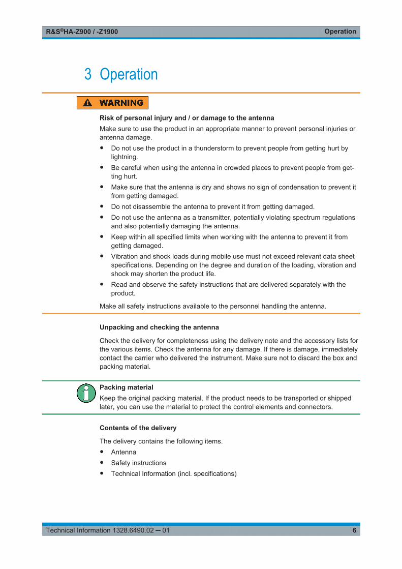
3 Operation
Risk of personal injury and / or damage to the antennaMake sure to use the product in an appropriate manner to prevent personal injuries orantenna damage.● Do not use the product in a thunderstorm to prevent people from getting hurt by
lightning.● Be careful when using the antenna in crowded places to prevent people from get-
ting hurt.● Make sure that the antenna is dry and shows no sign of condensation to prevent it
from getting damaged.● Do not disassemble the antenna to prevent it from getting damaged.● Do not use the antenna as a transmitter, potentially violating spectrum regulations
and also potentially damaging the antenna.● Keep within all specified limits when working with the antenna to prevent it from
getting damaged.● Vibration and shock loads during mobile use must not exceed relevant data sheet
specifications. Depending on the degree and duration of the loading, vibration andshock may shorten the product life.
● Read and observe the safety instructions that are delivered separately with theproduct.
Make all safety instructions available to the personnel handling the antenna.
Unpacking and checking the antenna
Check the delivery for completeness using the delivery note and the accessory lists forthe various items. Check the antenna for any damage. If there is damage, immediatelycontact the carrier who delivered the instrument. Make sure not to discard the box andpacking material.
Packing materialKeep the original packing material. If the product needs to be transported or shippedlater, you can use the material to protect the control elements and connectors.
Contents of the delivery
The delivery contains the following items.● Antenna● Safety instructions● Technical Information (incl. specifications)

OperationR&S®HA-Z900 / -Z1900
7Technical Information 1328.6490.02 ─ 01
Connectors
The Yagi antennas have an RF connector in their handles. The female RF connectorwith an impedance of 50 Ω allows you to connect the antenna to a spectrum analyzerwith an appropriate cable.
Risk of damage to the antennaMake sure not to overload the RF input and keep within the maximum allowed signallevels.See Chapter 1, "Specifications R&S®HA-Z900", on page 4 and Chapter 2, "Specifica-tions R&S®HA-Z1900", on page 5 for details.
Recommended measurement equipment
Using the antenna requires an RF cable to connect it to a signal and spectrum ana-lyzer.
Recommended cables:● R&S®HA-Z901 RF Cable (3626.2757.02)
Recommended spectrum analyzers:● R&S®Spectrum Rider FPH● R&S®FSH● R&S®ZVH
Other equipment:● R&S®HA-Z901 Carrying Bag (1328.6883.02)
Measurement setup
1. Connect one end of the RF cable to the RF input (a female N connector) of theantenna.The RF input is integrated into the handle of the antenna.
2. Connect the other end of the cable to the RF input of the R&S®Spectrum RiderFPH.
OperationR&S®HA-Z900 / -Z1900
8Technical Information 1328.6490.02 ─ 01
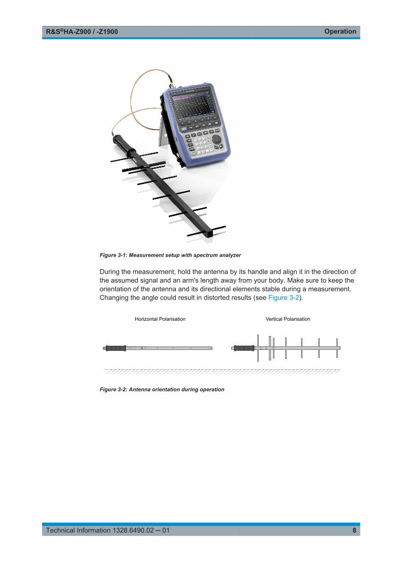
Figure 3-1: Measurement setup with spectrum analyzer
During the measurement, hold the antenna by its handle and align it in the direction ofthe assumed signal and an arm's length away from your body. Make sure to keep theorientation of the antenna and its directional elements stable during a measurement.Changing the angle could result in distorted results (see Figure 3-2).
Horizontal Polarisation Vertical Polarisation
Figure 3-2: Antenna orientation during operation

MaintenanceR&S®HA-Z900 / -Z1900
9Technical Information 1328.6490.02 ─ 01
4 MaintenanceIn case of functional errors, check the antenna for possible damage.
Visual inspection
Visual inspection is a basic check to verify that the hardware is not damaged. Checkthe driven element, the directors and the reflector and the stabilizer bar for complete-ness and visual damage.
If one of the elements mentioned is missing, bent, broken or torn off, the antenna hasto be repaired or replaced.
Electric functional test
An electronic functional test requires a network analyzer to measure the VSWR. Thetest should be done in an empty room (no interfering, especially metallic, objects aswell as other persons should be present).
In case of a working antenna, the results should conform to the following specificationsin the antenna's specified frequency range (see Chapter 1, "Specifications R&S®HA-Z900", on page 4 and Chapter 2, "Specifications R&S®HA-Z1900", on page 5).● VSWR < 2.5:1
If the antenna does not work as expected, contact the Rohde & Schwarz support.


![Cheryl's Hot Flashes #5 [S]watsonwalker.s3.us-west-1.amazonaws.com/ww/wp-content/... · 2016. 1. 28. · ONo word yet on ADRDSSU. 12 Session 2543 - Cheryl’s Hot Flashes #5 z900](https://img.pdfslide.net/doc/110x75/60b33bd9fbadb2385428981b/cheryls-hot-flashes-5-swatsonwalkers3us-west-1-2016-1-28-ono-word-yet.jpg)


![Cheryl's Hot Flashes #5 [S]s3-us-west-1.amazonaws.com/watsonwalker/ww/wp-content/uploads… · 4 Session 2543 - Cheryl’s Hot Flashes #5 R10 LSPRs OR10 and z900 benchmarks: QTSO](https://img.pdfslide.net/doc/110x75/5fd91ff2a1c9b154545c4c6c/cheryls-hot-flashes-5-ss3-us-west-1-4-session-2543-cherylas-hot-flashes.jpg)