Embed Size (px)
Citation preview
Technical InformationIFCON Inline-Fuse-Connector-Set16
Sicherungssteckverb-TI-en-11 | Version 1.1 ENGLISH
Table of Contents1 Product Description....................................................................................................................... 3
1.1 Inline Fuse Connector....................................................................................................................................... 31.2 Circuitry Options with Inline String Fuses........................................................................................................ 3
2 Fuse Rating.................................................................................................................................... 6
3 Mounting ....................................................................................................................................... 83.1 Requirements for the Mounting Location ........................................................................................................ 83.2 Mounting and Disassembling the Inline Fuse Connectors ............................................................................. 8
4 Technical Data............................................................................................................................... 9
5 Accessories .................................................................................................................................... 10
Table of Contents SMA Solar Technology AG
Technical InformationSicherungssteckverb-TI-en-112
1 Product Description
1.1 Inline Fuse ConnectorThe inline fuse connector is a string fuse which protects strings against reverse currents. The inline fuse connector isconnected to DC connectors or Y adapters of the SUNCLIX plug-in system.SMA Solar Technology AG offers the inline fuse connector as set with 16 connectors.
Designation Brief description SMA order number
Inline fuse connector set Inline fuse connector set consisting of16 PV inline fuse connectorsThe following sizes for input voltagesup to 1,000 V DC and up to 1,500 VDC are available: 6 A, 8 A, 10 A,12 A, 15 A, 20 A, 25 A, 30 A
IFCON16Sxx10 or IFCON16Sxx15*
* The order number of a fuse with an input voltage of 1,000 VDCis "IFCON16Sxx10". The order number of a fuse with an input voltage of1,500 VDCis "IFCON16Sxx15". xx in the order number has to be replaced with the fuse size. Example: A fuse with an input voltage ofup to 1,000 VDC, size 12 A has the order number "IFCON16S1210".
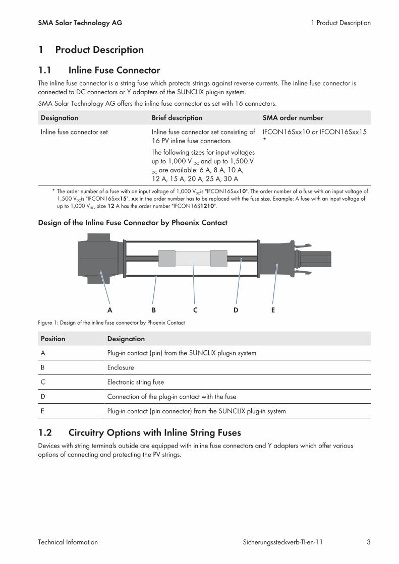
Design of the Inline Fuse Connector by Phoenix Contact
Figure 1: Design of the inline fuse connector by Phoenix Contact
Position Designation
A Plug-in contact (pin) from the SUNCLIX plug-in system
B Enclosure
C Electronic string fuse
D Connection of the plug-in contact with the fuse
E Plug-in contact (pin connector) from the SUNCLIX plug-in system
1.2 Circuitry Options with Inline String FusesDevices with string terminals outside are equipped with inline fuse connectors and Y adapters which offer variousoptions of connecting and protecting the PV strings.
1 Product DescriptionSMA Solar Technology AG
Technical Information 3Sicherungssteckverb-TI-en-11
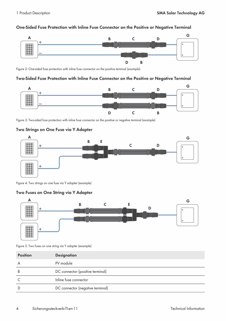
One-Sided Fuse Protection with Inline Fuse Connector on the Positive or Negative Terminal
Figure 2: One-sided fuse protection with inline fuse connector on the positive terminal (example)
Two-Sided Fuse Protection with Inline Fuse Connector on the Positive or Negative Terminal
Figure 3: Two-sided fuse protection with inline fuse connector on the positive or negative terminal (example)
Two Strings on One Fuse via Y Adapter
Figure 4: Two strings on one fuse via Y adapter (example)
Two Fuses on One String via Y Adapter
Figure 5: Two fuses on one string via Y adapter (example)
Position Designation
A PV module
B DC connector (positive terminal)
C Inline fuse connector
D DC connector (negative terminal)
1 Product Description SMA Solar Technology AG
Technical InformationSicherungssteckverb-TI-en-114
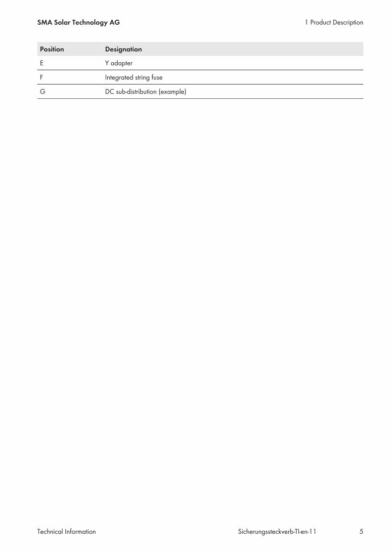
Position Designation
E Y adapter
F Integrated string fuse
G DC sub-distribution (example)
1 Product DescriptionSMA Solar Technology AG
Technical Information 5Sicherungssteckverb-TI-en-11
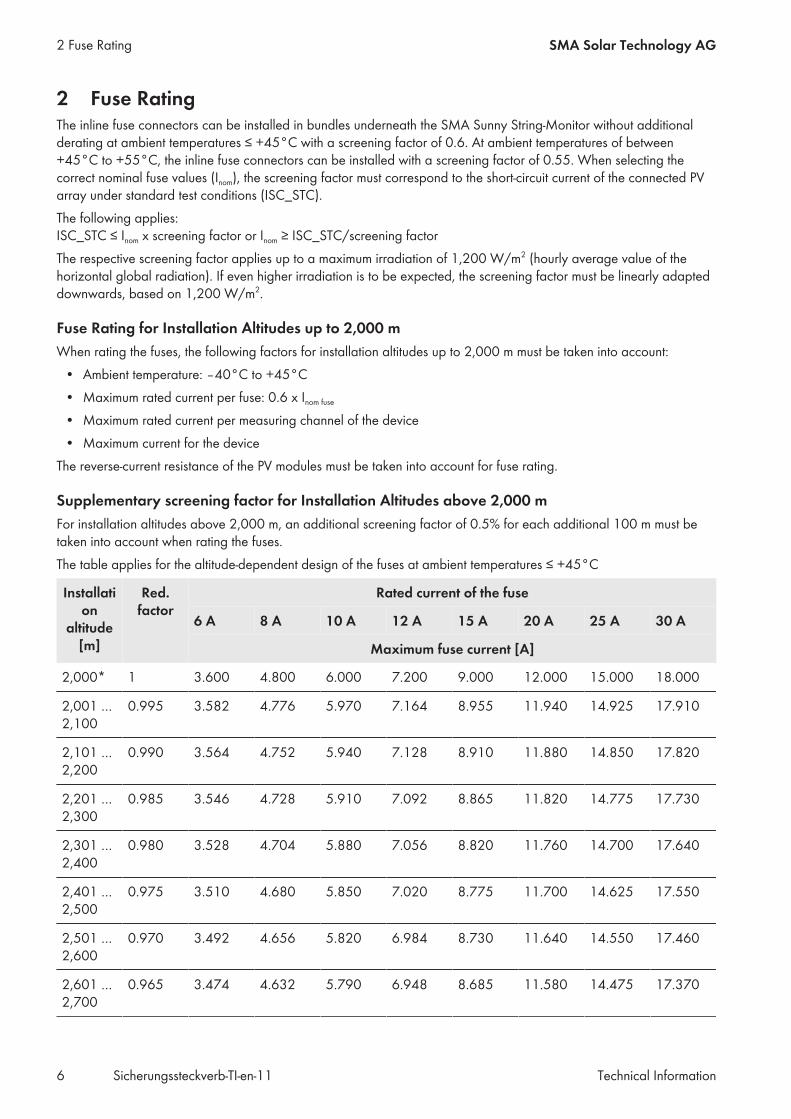
2 Fuse RatingThe inline fuse connectors can be installed in bundles underneath the SMA Sunny String-Monitor without additionalderating at ambient temperatures ≤ +45°C with a screening factor of 0.6. At ambient temperatures of between+45°C to +55°C, the inline fuse connectors can be installed with a screening factor of 0.55. When selecting thecorrect nominal fuse values (Inom), the screening factor must correspond to the short-circuit current of the connected PVarray under standard test conditions (ISC_STC).The following applies: ISC_STC ≤ Inom x screening factor or Inom ≥ ISC_STC/screening factorThe respective screening factor applies up to a maximum irradiation of 1,200 W/m2 (hourly average value of thehorizontal global radiation). If even higher irradiation is to be expected, the screening factor must be linearly adapteddownwards, based on 1,200 W/m2.
Fuse Rating for Installation Altitudes up to 2,000 mWhen rating the fuses, the following factors for installation altitudes up to 2,000 m must be taken into account:
• Ambient temperature: ‒40°C to +45°C• Maximum rated current per fuse: 0.6 x Inom fuse
• Maximum rated current per measuring channel of the device• Maximum current for the device
The reverse-current resistance of the PV modules must be taken into account for fuse rating.
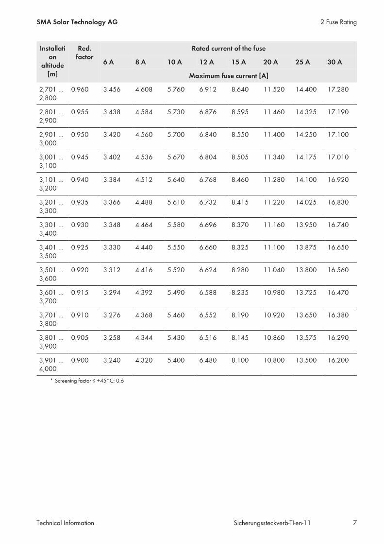
Supplementary screening factor for Installation Altitudes above 2,000 mFor installation altitudes above 2,000 m, an additional screening factor of 0.5% for each additional 100 m must betaken into account when rating the fuses.The table applies for the altitude-dependent design of the fuses at ambient temperatures ≤ +45°C
Installation
altitude[m]
Red.factor
Rated current of the fuse
6 A 8 A 10 A 12 A 15 A 20 A 25 A 30 A
Maximum fuse current [A]
2,000* 1 3.600 4.800 6.000 7.200 9.000 12.000 15.000 18.000
2,001 …2,100
0.995 3.582 4.776 5.970 7.164 8.955 11.940 14.925 17.910
2,101 …2,200
0.990 3.564 4.752 5.940 7.128 8.910 11.880 14.850 17.820
2,201 …2,300
0.985 3.546 4.728 5.910 7.092 8.865 11.820 14.775 17.730
2,301 …2,400
0.980 3.528 4.704 5.880 7.056 8.820 11.760 14.700 17.640
2,401 …2,500
0.975 3.510 4.680 5.850 7.020 8.775 11.700 14.625 17.550
2,501 …2,600
0.970 3.492 4.656 5.820 6.984 8.730 11.640 14.550 17.460
2,601 …2,700
0.965 3.474 4.632 5.790 6.948 8.685 11.580 14.475 17.370
2 Fuse Rating SMA Solar Technology AG
Technical InformationSicherungssteckverb-TI-en-116
Installation
altitude[m]
Red.factor
Rated current of the fuse
6 A 8 A 10 A 12 A 15 A 20 A 25 A 30 A
Maximum fuse current [A]
2,701 …2,800
0.960 3.456 4.608 5.760 6.912 8.640 11.520 14.400 17.280
2,801 …2,900
0.955 3.438 4.584 5.730 6.876 8.595 11.460 14.325 17.190
2,901 …3,000
0.950 3.420 4.560 5.700 6.840 8.550 11.400 14.250 17.100
3,001 …3,100
0.945 3.402 4.536 5.670 6.804 8.505 11.340 14.175 17.010
3,101 …3,200
0.940 3.384 4.512 5.640 6.768 8.460 11.280 14.100 16.920
3,201 …3,300
0.935 3.366 4.488 5.610 6.732 8.415 11.220 14.025 16.830
3,301 …3,400
0.930 3.348 4.464 5.580 6.696 8.370 11.160 13.950 16.740
3,401 …3,500
0.925 3.330 4.440 5.550 6.660 8.325 11.100 13.875 16.650
3,501 …3,600
0.920 3.312 4.416 5.520 6.624 8.280 11.040 13.800 16.560
3,601 …3,700
0.915 3.294 4.392 5.490 6.588 8.235 10.980 13.725 16.470
3,701 …3,800
0.910 3.276 4.368 5.460 6.552 8.190 10.920 13.650 16.380
3,801 …3,900
0.905 3.258 4.344 5.430 6.516 8.145 10.860 13.575 16.290
3,901 …4,000
0.900 3.240 4.320 5.400 6.480 8.100 10.800 13.500 16.200
* Screening factor ≤ +45°C: 0.6
2 Fuse RatingSMA Solar Technology AG
Technical Information 7Sicherungssteckverb-TI-en-11
3 Mounting
3.1 Requirements for the Mounting Location☐ Ambient temperature: ‒40°C to +55°C☐ The inline fuse connectors must not be in contact with surrounding objects with temperatures exceeding +55°C.
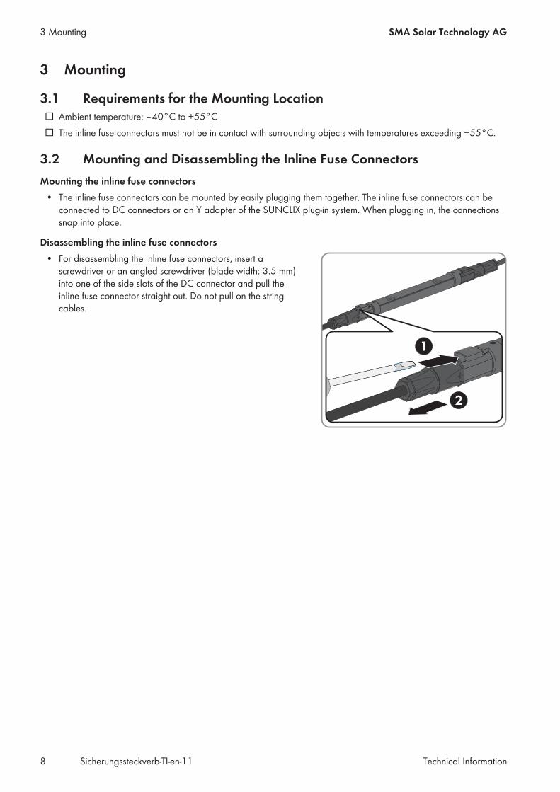
3.2 Mounting and Disassembling the Inline Fuse ConnectorsMounting the inline fuse connectors
• The inline fuse connectors can be mounted by easily plugging them together. The inline fuse connectors can beconnected to DC connectors or an Y adapter of the SUNCLIX plug-in system. When plugging in, the connectionssnap into place.
Disassembling the inline fuse connectors• For disassembling the inline fuse connectors, insert a
screwdriver or an angled screwdriver (blade width: 3.5 mm)into one of the side slots of the DC connector and pull theinline fuse connector straight out. Do not pull on the stringcables.
3 Mounting SMA Solar Technology AG
Technical InformationSicherungssteckverb-TI-en-118
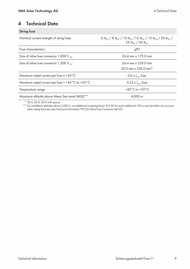
4 Technical DataString fuse
Nominal current strength of string fuses 6 ADC / 8 ADC / 10 ADC /12 ADC / 15 ADC / 20 ADC /25 ADC / 30 ADC
Fuse characteristics gPV
Size of inline fuse connector 1,000 V DC 26.4 mm x 175.0 mm
Size of inline fuse connector 1,500 V DC 26.4 mm x 220.0 mm30.0 mm x 220.0 mm*
Maximum rated current per fuse ≤ +45°C 0.6 x Inom fuse
Maximum rated current per fuse > +45°C to +55°C 0.55 x Inom fuse
Temperature range ‒40°C to +55°C
Maximum altitude above Mean Sea Level (MSL)** 4,000 m* 20 A, 25 A, 30 A with spacer
** For installation altitudes above 2,000 m, an additional screening factor of 0.5% for each additional 100 m must be taken into accountwhen rating the fuses (see Technical Information "IFCON Inline Fuse Connector Set16").
4 Technical DataSMA Solar Technology AG
Technical Information 9Sicherungssteckverb-TI-en-11
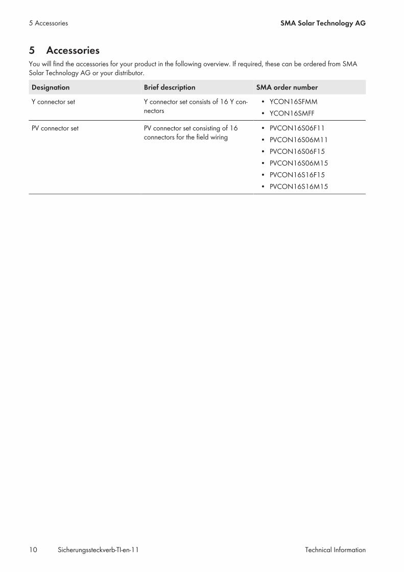
5 AccessoriesYou will find the accessories for your product in the following overview. If required, these can be ordered from SMASolar Technology AG or your distributor.
Designation Brief description SMA order number
Y connector set Y connector set consists of 16 Y con-nectors
• YCON16SFMM• YCON16SMFF
PV connector set PV connector set consisting of 16connectors for the field wiring
• PVCON16S06F11• PVCON16S06M11• PVCON16S06F15• PVCON16S06M15• PVCON16S16F15• PVCON16S16M15
5 Accessories SMA Solar Technology AG
Technical InformationSicherungssteckverb-TI-en-1110


SMA Solar Technology
www.SMA-Solar.com