Embed Size (px)
Citation preview

TI345F/24/ae
Technical Information
Micropilot M FMR230/231/240/244/245
Level-Radar
Smart transmitter for continuous and non-contact level
measurement. Cost-effective 4 to 20 mA 2-wire technology.
Suitable for hazardous locations.
Application
The Micropilot M is used for continuous, non-contact
level measurement of liquids, pastes, and slurries.
The measurement is not affected by changing media,
temperature changes, gas blankets or vapors.
• The FMR230 is especially suited for measurement in
buffer and process tanks.
• The FMR231 has its strengths wherever high chemical
compatibility is required.
• The FMR240 with the small (1-½") horn antenna is
ideally suited for small vessels. Additionally, it provides
an accuracy of ± 0.12" (3 mm).
• The FMR244 combines the advantages of the horn
antenna with high chemical resistance.
• The FMR245 - highly resistant, easy to clean.
Your benefits
• 2-wire technology, low price:
A real alternative to differential pressure, floats and
displacers. 2-wire technology reduces wiring costs and
allows easy implementation into existing systems.
• Non-contact measurement:
Measurement is almost independent from product
properties.
• Easy local operation via menu-driven alphanumeric
display.
• Easy commissioning, documentation and diagnostics
via operating software (ToF Tool).
• 2 frequency ranges - FMR230/FMR231 in the C-band
and FMR240/244/245 in the K-band: No
compromises, the right frequency for every
application.
• HART® or PROFIBUS® PA respectively
FOUNDATION™ Fieldbus protocol.
• High temperatures:
Suitable for process temperatures up to 392°F
(200°C), up to 752°F (400°C) with high-temperature
antenna.
• Rod antenna with inactive length:
Reliable measurement in narrow nozzles, with
condensation and build-up in the nozzle.
• Application in safety related systems (overspill
protection) with requirements for functional safety up
to SIL 2 in accordance to IEC 61508/IEC 61511-1.
Micropilot M
2 Endress+Hauser
Table of contents
Function and system design. . . . . . . . . . . . . . . . . . . . . 3
Measuring principle . . . . . . . . . . . . . . . . . . . . . . . . . . . . . . . . . . . 3
Equipment architecture . . . . . . . . . . . . . . . . . . . . . . . . . . . . . . . . 4
Input . . . . . . . . . . . . . . . . . . . . . . . . . . . . . . . . . . . . . . 8
Measured variable . . . . . . . . . . . . . . . . . . . . . . . . . . . . . . . . . . . . 8
Measuring range . . . . . . . . . . . . . . . . . . . . . . . . . . . . . . . . . . . . . . 8
Measuring conditions . . . . . . . . . . . . . . . . . . . . . . . . . . . . . . . . . 12
Operating frequency . . . . . . . . . . . . . . . . . . . . . . . . . . . . . . . . . . 13
Transmitting power . . . . . . . . . . . . . . . . . . . . . . . . . . . . . . . . . . 13
Output . . . . . . . . . . . . . . . . . . . . . . . . . . . . . . . . . . . . 13
Output signal . . . . . . . . . . . . . . . . . . . . . . . . . . . . . . . . . . . . . . . 13
Signal on alarm . . . . . . . . . . . . . . . . . . . . . . . . . . . . . . . . . . . . . 13
Linearization . . . . . . . . . . . . . . . . . . . . . . . . . . . . . . . . . . . . . . . 13
Auxiliary energy . . . . . . . . . . . . . . . . . . . . . . . . . . . . 14
Electrical connection . . . . . . . . . . . . . . . . . . . . . . . . . . . . . . . . . 14
Cable gland . . . . . . . . . . . . . . . . . . . . . . . . . . . . . . . . . . . . . . . . 14
Terminals . . . . . . . . . . . . . . . . . . . . . . . . . . . . . . . . . . . . . . . . . . 14
Terminal assignment . . . . . . . . . . . . . . . . . . . . . . . . . . . . . . . . . 15
Fieldbus plug connectors . . . . . . . . . . . . . . . . . . . . . . . . . . . . . . 16
Load HART . . . . . . . . . . . . . . . . . . . . . . . . . . . . . . . . . . . . . . . . 16
Supply voltage . . . . . . . . . . . . . . . . . . . . . . . . . . . . . . . . . . . . . . 16
Cable entry . . . . . . . . . . . . . . . . . . . . . . . . . . . . . . . . . . . . . . . . 16
Power consumption . . . . . . . . . . . . . . . . . . . . . . . . . . . . . . . . . . 17
Current consumption . . . . . . . . . . . . . . . . . . . . . . . . . . . . . . . . . 17
Ripple HART . . . . . . . . . . . . . . . . . . . . . . . . . . . . . . . . . . . . . . . 17
Max. noise HART . . . . . . . . . . . . . . . . . . . . . . . . . . . . . . . . . . . . 17
Overvoltage protector . . . . . . . . . . . . . . . . . . . . . . . . . . . . . . . . . 17
Performance characteristics. . . . . . . . . . . . . . . . . . . . 18
Reference operating conditions . . . . . . . . . . . . . . . . . . . . . . . . . . 18
Maximum measured error . . . . . . . . . . . . . . . . . . . . . . . . . . . . . 18
Resolution . . . . . . . . . . . . . . . . . . . . . . . . . . . . . . . . . . . . . . . . . 18
Reaction time . . . . . . . . . . . . . . . . . . . . . . . . . . . . . . . . . . . . . . . 18
Influence of ambiente temperature . . . . . . . . . . . . . . . . . . . . . . . 18
Effect of gas phase . . . . . . . . . . . . . . . . . . . . . . . . . . . . . . . . . . . 19
Operating conditions: Installation . . . . . . . . . . . . . . . 20
Installation instructions . . . . . . . . . . . . . . . . . . . . . . . . . . . . . . . . 20
Beam angle . . . . . . . . . . . . . . . . . . . . . . . . . . . . . . . . . . . . . . . . 22
Installation in tank (free space) FMR230 . . . . . . . . . . . . . . . . . . . 23
Installation FMR230 with heat insulation . . . . . . . . . . . . . . . . . . 26
Installation in tank (free space) FMR231 . . . . . . . . . . . . . . . . . . . 27
Installation in tank (free space) FMR240, 244, 245 . . . . . . . . . . . 28
Installation in stilling well FMR230, 240, 244, 245 . . . . . . . . . . . 30
Installation in bypass FMR230, 240, 245 . . . . . . . . . . . . . . . . . . 32
Operating conditions: Environment. . . . . . . . . . . . . . 34
Ambient temperature range . . . . . . . . . . . . . . . . . . . . . . . . . . . . 34
Storage temperature . . . . . . . . . . . . . . . . . . . . . . . . . . . . . . . . . . 34
Climate class . . . . . . . . . . . . . . . . . . . . . . . . . . . . . . . . . . . . . . . 34
Degree of protection . . . . . . . . . . . . . . . . . . . . . . . . . . . . . . . . . . 34
Vibration resistance . . . . . . . . . . . . . . . . . . . . . . . . . . . . . . . . . . 34
Cleaning of the antenna . . . . . . . . . . . . . . . . . . . . . . . . . . . . . . . 34
Electromagnetic compatibility . . . . . . . . . . . . . . . . . . . . . . . . . . . 34
Operating conditions: Process . . . . . . . . . . . . . . . . . . 35
Process temperature range/Process pressure limits . . . . . . . . . . . 35
Dielectric constant . . . . . . . . . . . . . . . . . . . . . . . . . . . . . . . . . . . 36
Mechanical construction . . . . . . . . . . . . . . . . . . . . . . 37
Design, dimensions . . . . . . . . . . . . . . . . . . . . . . . . . . . . . . . . . . 37
Weight . . . . . . . . . . . . . . . . . . . . . . . . . . . . . . . . . . . . . . . . . . . 43
Material . . . . . . . . . . . . . . . . . . . . . . . . . . . . . . . . . . . . . . . . . . . 43
Process connection . . . . . . . . . . . . . . . . . . . . . . . . . . . . . . . . . . 43
Seal . . . . . . . . . . . . . . . . . . . . . . . . . . . . . . . . . . . . . . . . . . . . . . 43
Antenna . . . . . . . . . . . . . . . . . . . . . . . . . . . . . . . . . . . . . . . . . . . 43
Human interface . . . . . . . . . . . . . . . . . . . . . . . . . . . . 44
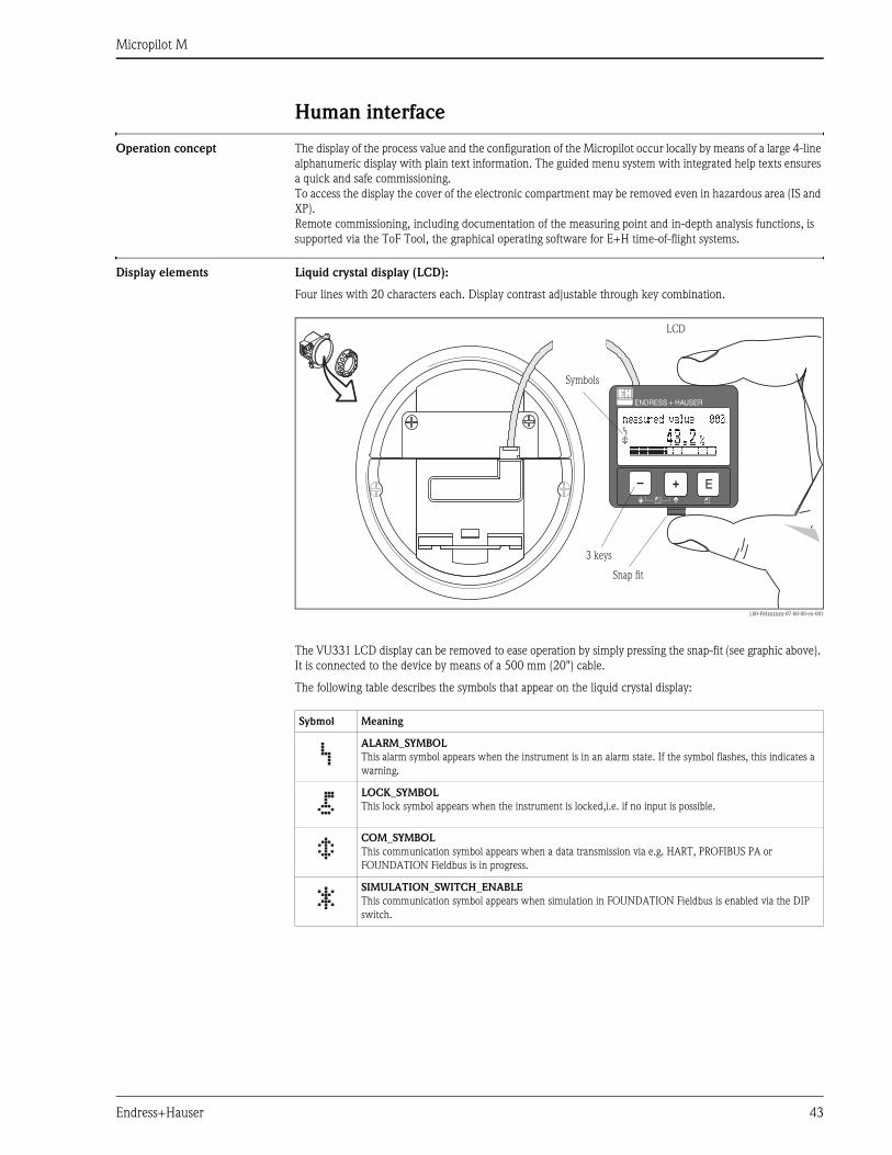
Operation concept . . . . . . . . . . . . . . . . . . . . . . . . . . . . . . . . . . . 44
Display elements . . . . . . . . . . . . . . . . . . . . . . . . . . . . . . . . . . . . 44
Operating elements . . . . . . . . . . . . . . . . . . . . . . . . . . . . . . . . . . 45
Local operation . . . . . . . . . . . . . . . . . . . . . . . . . . . . . . . . . . . . . 46
Remote operation . . . . . . . . . . . . . . . . . . . . . . . . . . . . . . . . . . . . 47
Certificates and approvals . . . . . . . . . . . . . . . . . . . . . 49
CE approval . . . . . . . . . . . . . . . . . . . . . . . . . . . . . . . . . . . . . . . . 49
Hazardous areas approval . . . . . . . . . . . . . . . . . . . . . . . . . . . . . . 49
Sanitary compatibility . . . . . . . . . . . . . . . . . . . . . . . . . . . . . . . . . 49
Overspill protection . . . . . . . . . . . . . . . . . . . . . . . . . . . . . . . . . . 49
Marine certificate . . . . . . . . . . . . . . . . . . . . . . . . . . . . . . . . . . . . 49
External standards and guidelines . . . . . . . . . . . . . . . . . . . . . . . . 49
RF approvals . . . . . . . . . . . . . . . . . . . . . . . . . . . . . . . . . . . . . . . 49
Pressure measuring device guideline . . . . . . . . . . . . . . . . . . . . . . 49
Ordering information. . . . . . . . . . . . . . . . . . . . . . . . . 50
Micropilot M FMR230 . . . . . . . . . . . . . . . . . . . . . . . . . . . . . . . . 50
Micropilot M FMR231 . . . . . . . . . . . . . . . . . . . . . . . . . . . . . . . . 53
Micropilot M FMR240 . . . . . . . . . . . . . . . . . . . . . . . . . . . . . . . . 56
Micropilot M FMR244 . . . . . . . . . . . . . . . . . . . . . . . . . . . . . . . . 59
Micropilot M FMR245 . . . . . . . . . . . . . . . . . . . . . . . . . . . . . . . . 61
Accessories . . . . . . . . . . . . . . . . . . . . . . . . . . . . . . . . 63
Weather protection cover . . . . . . . . . . . . . . . . . . . . . . . . . . . . . . 63
Antenna extension FAR10 (for FMR230) . . . . . . . . . . . . . . . . . . 63
Remote display FHX40 . . . . . . . . . . . . . . . . . . . . . . . . . . . . . . . . 64
Commubox FXA191 HART . . . . . . . . . . . . . . . . . . . . . . . . . . . . 64
Commubox FXA195 HART . . . . . . . . . . . . . . . . . . . . . . . . . . . . 65
Commubox FXA291 . . . . . . . . . . . . . . . . . . . . . . . . . . . . . . . . . 65
ToF Adapter FXA291 . . . . . . . . . . . . . . . . . . . . . . . . . . . . . . . . . 65
Documentation . . . . . . . . . . . . . . . . . . . . . . . . . . . . . 66
System Information . . . . . . . . . . . . . . . . . . . . . . . . . . . . . . . . . . 66
Special Documentation . . . . . . . . . . . . . . . . . . . . . . . . . . . . . . . 66
Technical Information . . . . . . . . . . . . . . . . . . . . . . . . . . . . . . . . 66
Operating Instructions . . . . . . . . . . . . . . . . . . . . . . . . . . . . . . . . 66
Certificates . . . . . . . . . . . . . . . . . . . . . . . . . . . . . . . . . . . . . . . . 67
Safety Manual . . . . . . . . . . . . . . . . . . . . . . . . . . . . . . . . . . . . . . 68
Micropilot M
Endress+Hauser 3
Function and system design
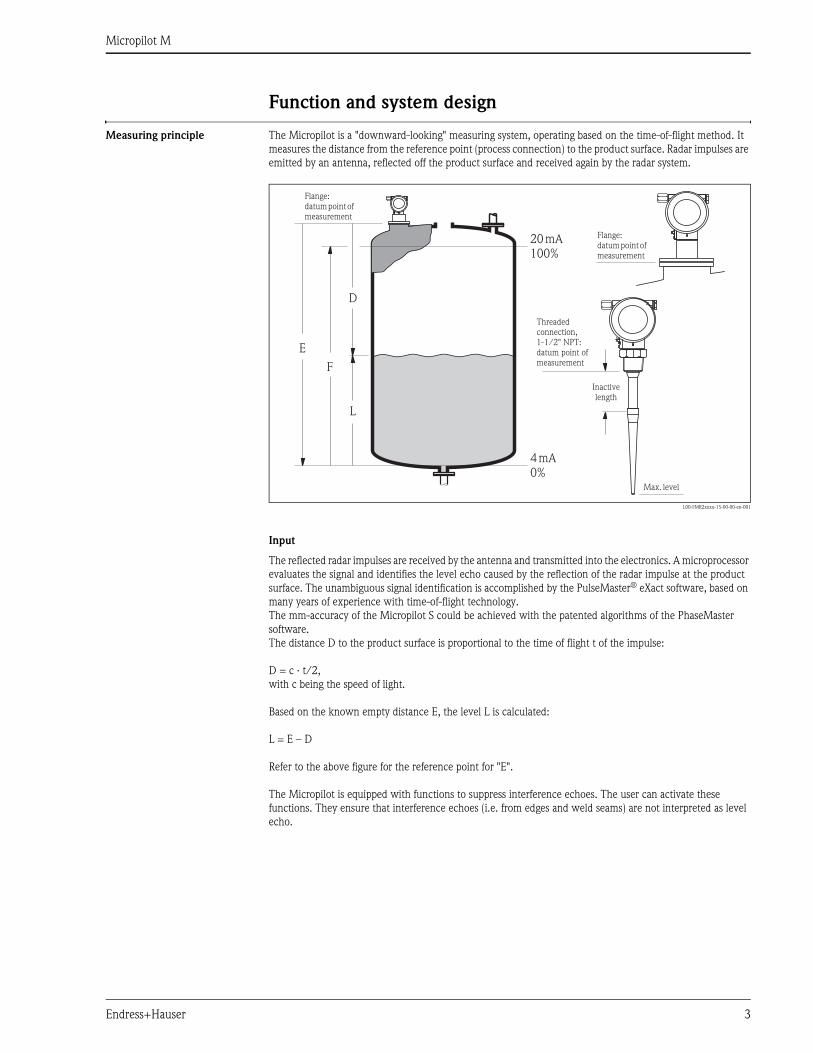
Measuring principle The Micropilot is a "downward-looking" measuring system, operating based on the time-of-flight method. It
measures the distance from the reference point (process connection) to the product surface. Radar impulses are
emitted by an antenna, reflected off the product surface and received again by the radar system.
L00-FMR2xxxx-15-00-00-en-001
Input
The reflected radar impulses are received by the antenna and transmitted into the electronics. A microprocessor
evaluates the signal and identifies the level echo caused by the reflection of the radar impulse at the product
surface. The unambiguous signal identification is accomplished by the PulseMaster® eXact software, based on
many years of experience with time-of-flight technology.
The mm-accuracy of the Micropilot S could be achieved with the patented algorithms of the PhaseMaster
software.
The distance D to the product surface is proportional to the time of flight t of the impulse:
D = c · t/2,
with c being the speed of light.
Based on the known empty distance E, the level L is calculated:
L = E – D
Refer to the above figure for the reference point for "E".
The Micropilot is equipped with functions to suppress interference echoes. The user can activate these
functions. They ensure that interference echoes (i.e. from edges and weld seams) are not interpreted as level
echo.
20mA100%
4mA0%
D
L
F
E
Flange:datumpoint ofmeasurement
Flange:datumpoint ofmeasurement
Inactivelength
Max. level
Threadedconnection,1-1/2" NPT:datum point ofmeasurement
Micropilot M
4 Endress+Hauser
Output
The Micropilot is commissioned by entering an empty distance E (=zero), a full distance F (=span) and an
application parameter. The application parameter automatically adapts the instrument to the process
conditions. The data points “E” and “F” correspond with 4mA and 20mA for instruments with current output.
They correspond with 0 % and 100 % for digital outputs and the display module.
A linearization with a maximum of 32 points, based on a table entered either manually or semi-automatically,
can be activated locally or remotely. This function provides a measurement in engineering units and a linear
output signal for spheres, horizontal cylindrical tanks and vessels with conical outlet.
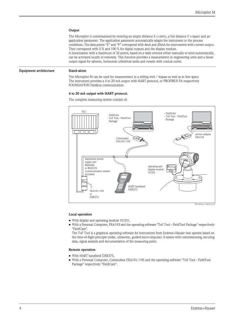
Equipment architecture Stand-alone
The Micropilot M can be used for measurement in a stilling well / bypass as well as in free space.
The instrument provides a 4 to 20 mA output with HART protocol, or PROFIBUS PA respectively
FOUNDATION Fieldbus communication.
4 to 20 mA output with HART protocol.
The complete measuring system consists of:
L00-FMR2xxxx-14-00-06-en-001
Local operation
• With display and operating module VU331,
• With a Personal Computer, FXA193 and the operating software "ToF Tool - FieldTool Package" respectively
"FieldCare".
The ToF Tool is a graphical operating software for instruments from Endress+Hauser that operate based on
the time-of-flight principle (radar, ultrasonic, guided micro-impulse). It assists with commissioning, securing
data, signal analysis and documentation of the measuring point.
Remote operation
• With HART handheld DXR375,
• With a Personal Computer, Commubox FXA191/195 and the operating software "ToF Tool - FieldTool
Package" respectively "FieldCare".
ENDRESS + HAUSER
E+–
%
ENDRESS + HAUSERRMA 422
1# % &
Copy
G H I
P Q R S
, ( ) ‘
A B C
Paste
PageOn
PageUp
DeleteBksp
Insert
J K L
T U V
_ < >
D E F
Hot Key
+ Hot Key
M N O
W X Y Z
+ * /
4
7
.
2
5
8
0
375FIELD COMMUNICATOR
3
6
9
-
9 6
DELTABAR: * * * * * * * *ONLINE
1 QUICK SETUP2 OPERATING MENU
4 SV 0 °C3 PV 352 mbar
HELP SAVE
dsdmdmdf das.
asdas faasas la.
- FieldCare- ToF Tool - FieldToolPackage
- FieldCare- ToF Tool - FieldToolPackage
CommuboxFXA191/195
HART handheldDXR375
FXA191/195orDXR375
transmitter powersupply unitRMA422or RN221N(communication resistorincluded)
PLC
operating anddisplay moduleVU331
service adapterFXA193
Micropilot M
Endress+Hauser 5
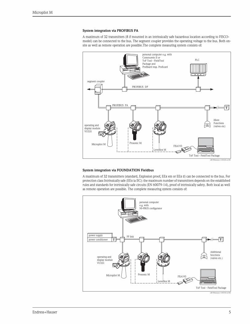
System integration via PROFIBUS PA
A maximum of 32 transmitters (8 if mounted in an intrinsically safe hazardous location according to FISCO-
model) can be connected to the bus. The segment coupler provides the operating voltage to the bus. Both on-
site as well as remote operation are possible.The complete measuring system consists of:
L00-FMxxxxxx-14-00-06-en-001
System integration via FOUNDATION Fieldbus
A maximum of 32 transmitters (standard, Explosion proof, EEx em or EEx d) can be connected to the bus. For
protection class Intrinsically safe (EEx ia IIC): the maximum number of transmitters depends on the established
rules and standards for intrinsically safe circuits (EN 60079-14), proof of intrinsically safety. Both local as well
as remote operation are possible. The complete measuring system consists of:
L00-FMxxxxxx-14-00-06-en-003
ENDRESS + HAUSER
FXA193Micropilot M
Prosonic M
Levelflex M
ENDRESS + HAUSER
E+–
%
T
PROFIBUS DP
PROFIBUS PA
ToF Tool - FieldTool Package
personal computer e.g. withCommuwin II orToF Tool - FieldToolPackage andProfibard resp. Proficard
segment coupler
PLC
operating anddisplay moduleVU331
MoreFunctions(valves etc)
T TFF link
FXA193
Levelflex M
ENDRESS + HAUSER
E+–
%
Prosonic MMicropilot M
ToF Tool - FieldTool Package
power supply
power conditioner
personal computere.g. withNI-FBUS configurator
operating anddisplay moduleVU331
Additionalfunctions(valves etc.)
Micropilot M
6 Endress+Hauser
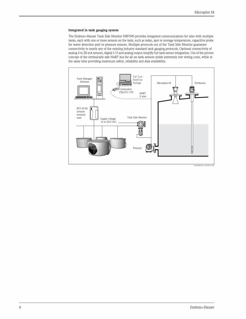
Integrated in tank gauging system
The Endress+Hauser Tank Side Monitor NRF590 provides integrated communications for sites with multiple
tanks, each with one or more sensors on the tank, such as radar, spot or average temperature, capacitive probe
for water detection and/or pressure sensors. Multiple protocols out of the Tank Side Monitor guarantee
connectivity to nearly any of the existing industry standard tank gauging protocols. Optional connectivity of
analog 4 to 20 mA sensors, digital I/O and analog output simplify full tank sensor integration. Use of the proven
concept of the intrinsically safe HART bus for all on-tank sensors yields extremely low wiring costs, while at
the same time providing maximum safety, reliability and data availability.
L00-FMR2xxxx-14-00-06-en-030
Micropilot M Prothermo
Tank Side Monitor
Fuels ManagerSoftware
RTU 8130(remoteterminalunit)
ToF Tool -FieldToolPackage
CommuboxFXA191/195
Pressure
HART2 wire
Supply voltage:16 to 253 VAC
Micropilot M
Endress+Hauser 7
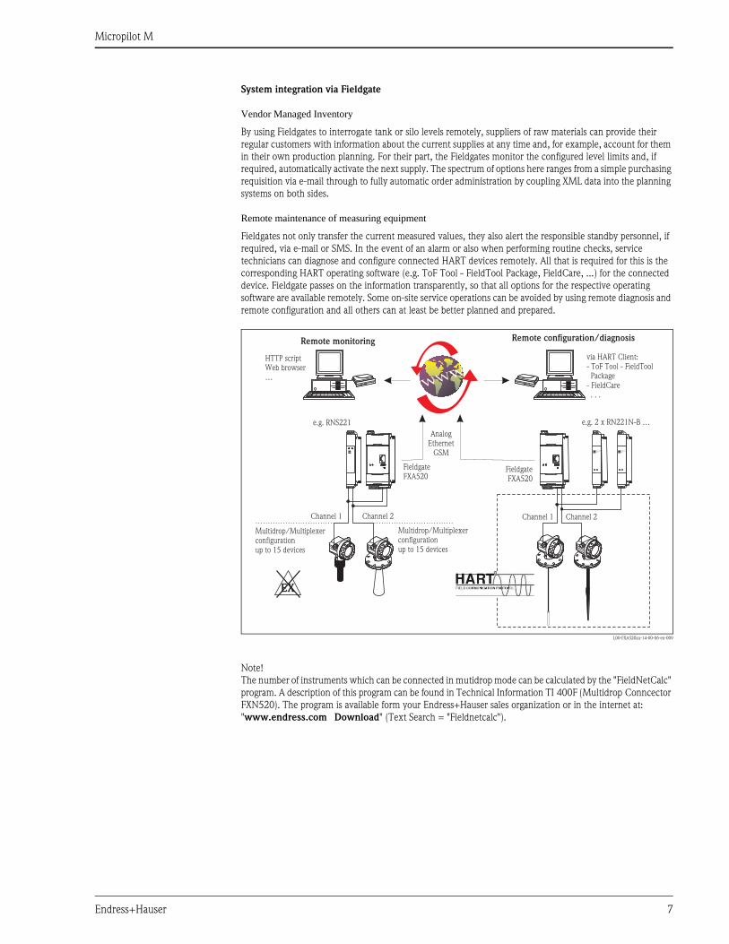
System integration via Fieldgate
Vendor Managed Inventory
By using Fieldgates to interrogate tank or silo levels remotely, suppliers of raw materials can provide their
regular customers with information about the current supplies at any time and, for example, account for them
in their own production planning. For their part, the Fieldgates monitor the configured level limits and, if
required, automatically activate the next supply. The spectrum of options here ranges from a simple purchasing
requisition via e-mail through to fully automatic order administration by coupling XML data into the planning
systems on both sides.
Remote maintenance of measuring equipment
Fieldgates not only transfer the current measured values, they also alert the responsible standby personnel, if
required, via e-mail or SMS. In the event of an alarm or also when performing routine checks, service
technicians can diagnose and configure connected HART devices remotely. All that is required for this is the
corresponding HART operating software (e.g. ToF Tool - FieldTool Package, FieldCare, ...) for the connected
device. Fieldgate passes on the information transparently, so that all options for the respective operating
software are available remotely. Some on-site service operations can be avoided by using remote diagnosis and
remote configuration and all others can at least be better planned and prepared.
L00-FXA520xx-14-00-06-en-009
Note!
The number of instruments which can be connected in mutidrop mode can be calculated by the "FieldNetCalc"
program. A description of this program can be found in Technical Information TI 400F (Multidrop Conncector
FXN520). The program is available form your Endress+Hauser sales organization or in the internet at:
"www.endress.com Download" (Text Search = "Fieldnetcalc").
FieldgateFXA520
FieldgateFXA520
ENDRESS+HAUSERRN 221N
ENDRESS+HAUSERRN 221N
AnalogEthernet
GSM
HTTP scriptWeb browser…
e.g. 2 x RN221N-B …e.g. RNS221
Channel 1 Channel 1
EX
Channel 2 Channel 2
via HART Client:- ToF Tool - FieldTool
Package- FieldCare
. . .
Remote monitoring Remote configuration/diagnosis
Multidrop/Multiplexerconfigurationup to 15 devices
Multidrop/Multiplexerconfigurationup to 15 devices
Micropilot M
8 Endress+Hauser
Input
Measured variable The measured variable is the distance between a reference point (refer to fig. on page 2) and a reflective surface
(i.e. medium surface).
The level is calculated based on the tank height entered.The level can be converted into other units (volume,
mass) by means of a linearization (32 points).
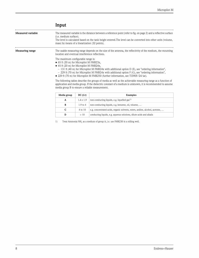
Measuring range The usable measuring range depends on the size of the antenna, the reflectivity of the medium, the mounting
location and eventual interference reflections.
The maximum configurable range is:
• 65 ft (20 m) for Micropilot M FMR23x,
• 65 ft (20 m) for Micropilot M FMR24x,
– 131 ft (40 m) for Micropilot M FMR24x with additional option D (E), see "ordering information",
– 229 ft (70 m) for Micropilot M FMR24x with additional option F (G), see "ordering information",
• 229 ft (70 m) for Micropilot M FMR250 (further information, see TI390F/24/ae).
The following tables describe the groups of media as well as the achievable measuring range as a function of
application and media group. If the dielectric constant of a medium is unknown, it is recommended to assume
media group B to ensure a reliable measurement.
Media group DC (εr) Examples
A 1.4 o 1.9 non-conducting liquids, e.g. liquefied gas1))
1) Treat Ammonia NH3 as a medium of group A, i.e. use FMR230 in a stilling well.
B 1.9 to 4 non-conducting liquids, e.g. benzene, oil, toluene, …
C 4 to 10 e.g. concentrated acids, organic solvents, esters, aniline, alcohol, acetone, …
D > 10 conducting liquids, e.g. aqueous solutions, dilute acids and alkalis
Micropilot M
Endress+Hauser 9
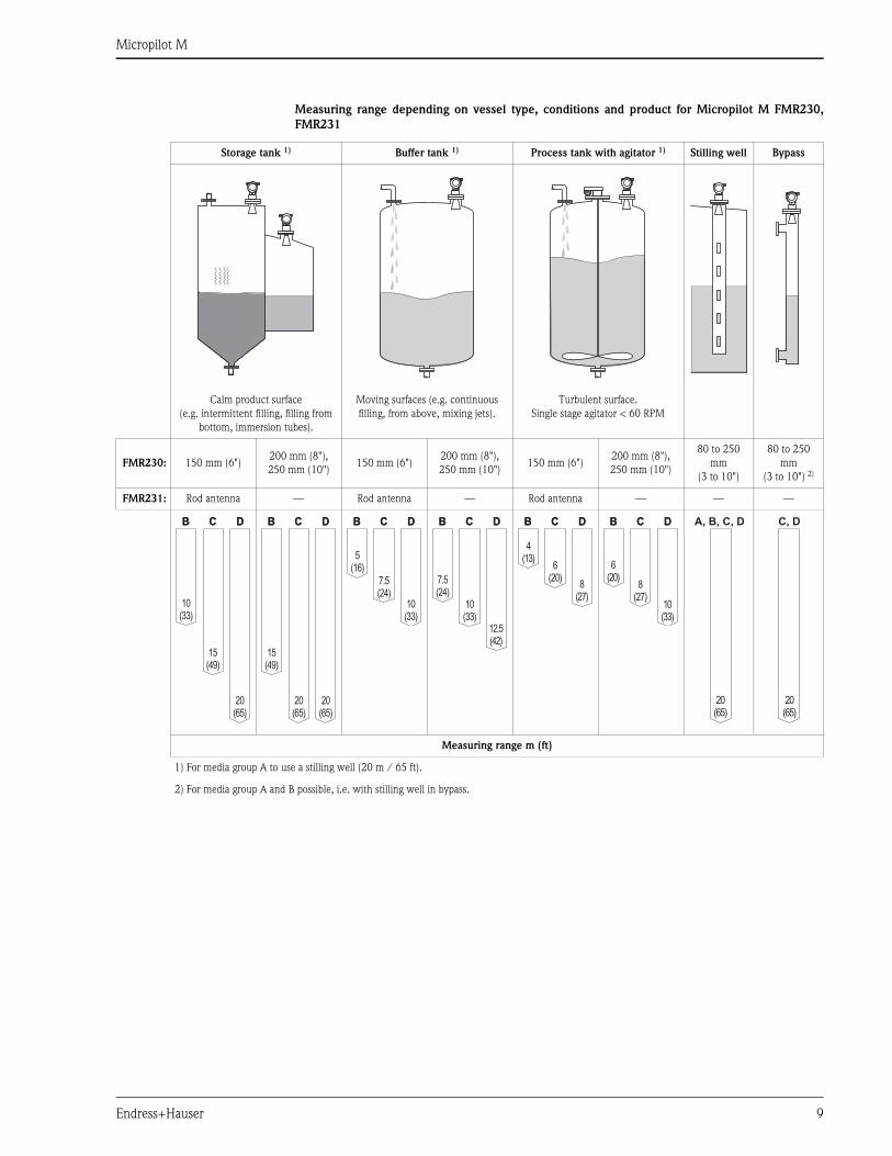
Measuring range depending on vessel type, conditions and product for Micropilot M FMR230,
FMR231
Storage tank 1) Buffer tank 1) Process tank with agitator 1) Stilling well Bypass
Calm product surface
(e.g. intermittent filling, filling from
bottom, immersion tubes).
Moving surfaces (e.g. continuous
filling, from above, mixing jets).
Turbulent surface.
Single stage agitator < 60 RPM
FMR230: 150 mm (6")200 mm (8"),
250 mm (10")150 mm (6")
200 mm (8"),
250 mm (10")150 mm (6")
200 mm (8"),
250 mm (10")
80 to 250
mm
(3 to 10")
80 to 250
mm
(3 to 10") 2)
FMR231: Rod antenna — Rod antenna — Rod antenna — — —
Measuring range m (ft)
1) For media group A to use a stilling well (20 m / 65 ft).
2) For media group A and B possible, i.e. with stilling well in bypass.
BB
10(33)
20(65)
15(49)
CC DD BB
20(65)
20(65)
15(49)
CC DD BB
10(33)
7.5(24)
5(16)
CC DD BB
12.5(42)
7.5(24)
10(33)
CC DD BB
8(27)
4(13)
6(20)
CC DD BB
10(33)
6(20)
8(27)
CC DD
20(65)
A, B, C, D
20(65)
C, D
Micropilot M
10 Endress+Hauser
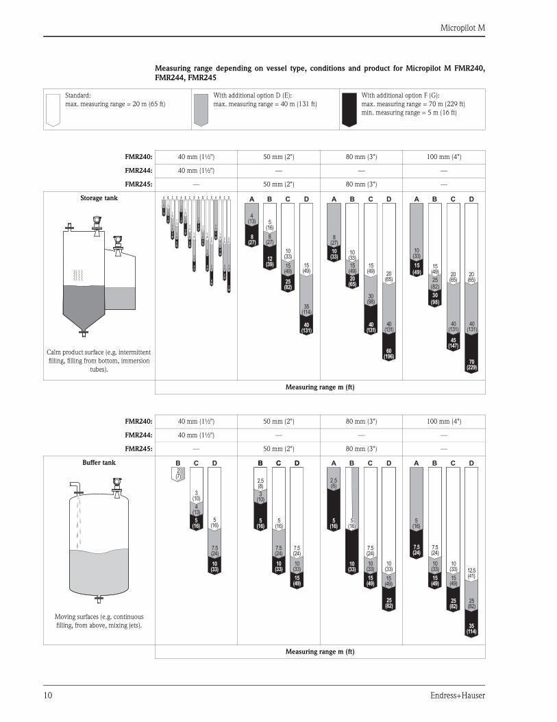
Measuring range depending on vessel type, conditions and product for Micropilot M FMR240,
FMR244, FMR245
Standard:
max. measuring range = 20 m (65 ft)
With additional option D (E):
max. measuring range = 40 m (131 ft)
With additional option F (G):
max. measuring range = 70 m (229 ft)
min. measuring range = 5 m (16 ft)
FMR240: 40 mm (1½") 50 mm (2") 80 mm (3") 100 mm (4")
FMR244: 40 mm (1½") — — —
FMR245: — 50 mm (2") 80 mm (3") —
Storage tank
Calm product surface (e.g. intermittent
filling, filling from bottom, immersion
tubes).
Measuring range m (ft)
A B
25(82)
15(49)
C D
9(30)
6(20)
3(10)
3(10)
10(33)
15(49)
5(16)
8(27)
5(16)
A B
12(39)
8(27)
25(82)
C D
5(16)
10(33)
8(27)
4(13)
15(49)
15(49)
35(114)
40(131)
A B
10(33)
20(65)
60(196)
C D
10(33)
15(49)
15(49)
8(27)
30(98)
40(131)
40(131)
20(65)
A B
30(98)
15(49)
C D
15(49) 20
(65)20(65)25
(82)
10(33)
40(131)
40(131)
70(229)
45(147)
A B
12(39)
8(27)
25(82)
C D
5(16)
10(33)
8(27)
4(13)
15(49)
15(49)
35(114)
40(131)
A B
10(33)
20(65)
60(196)
C D
10(33)
15(49)
15(49)
8(27)
30(98)
40(131)
40(131)
20(65)
A B
30(98)
15(49)
C D
15(49) 20
(65)20(65)25
(82)
10(33)
40(131)
40(131)
70(229)
45(147)
FMR240: 40 mm (1½") 50 mm (2") 80 mm (3") 100 mm (4")
FMR244: 40 mm (1½") — — —
FMR245: — 50 mm (2") 80 mm (3") —
Buffer tank
Moving surfaces (e.g. continuous
filling, from above, mixing jets).
Measuring range m (ft)
B
10(33)
C D
5(16)
5(16)
3(10)
4(13)
7.5(24)
2(7)
BB
5(16)
15(49)
10(33)
CC DD
2.5(8)
7.5
5
5(16)
3(10)
7.5(24)
7.5(24)
10(33)
A B
10(33)
5(16)
25(82)
15(49)
C D
7.5(24)
2.5(8)
10(33)
10(33)
15(49)
5(16)
A B C D
7.5(24)
7.5(24)
12.5(41)
10(33)
10(33)
5(16)
15(49)
15(49)
25(82)
25(82)
35(114)
Micropilot M
Endress+Hauser 11
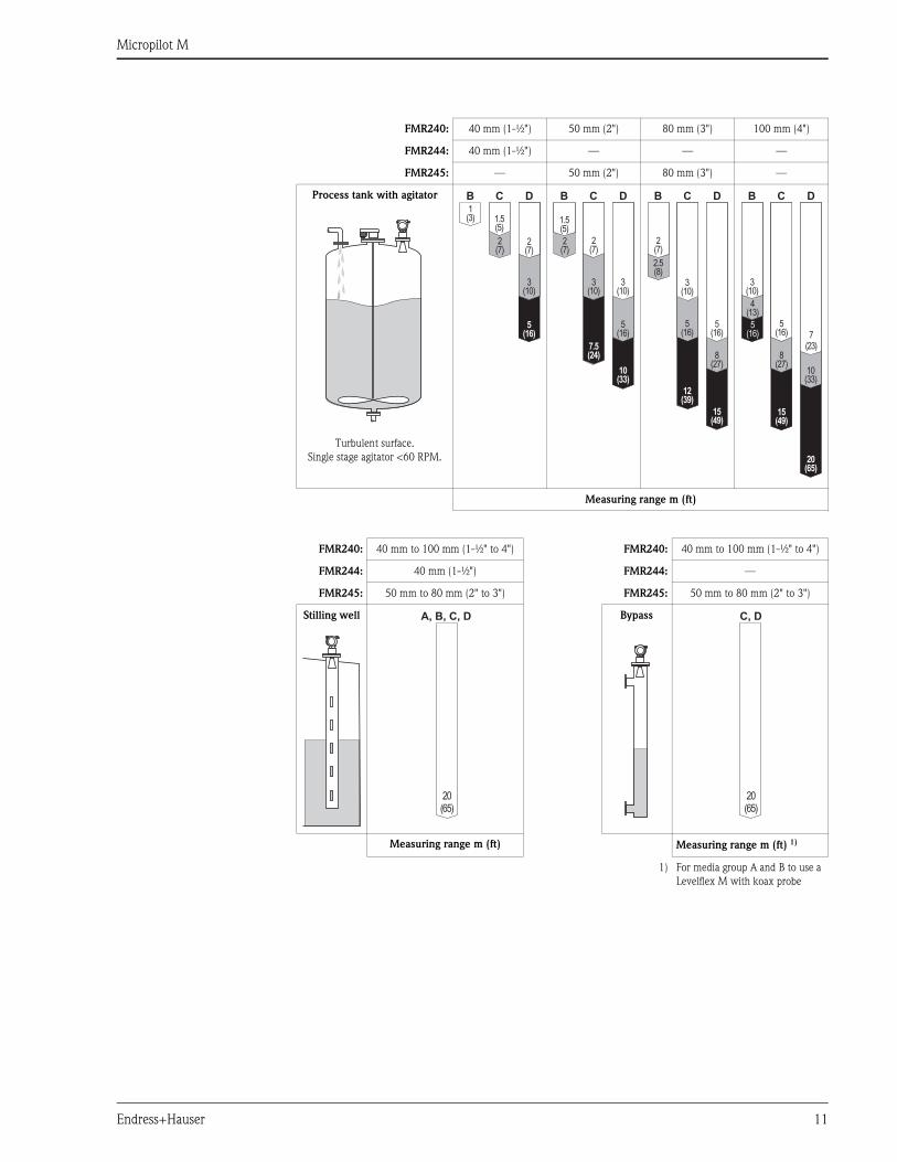
FMR240: 40 mm (1-½") 50 mm (2") 80 mm (3") 100 mm (4")
FMR244: 40 mm (1-½") — — —
FMR245: — 50 mm (2") 80 mm (3") —
Process tank with agitator
Turbulent surface.
Single stage agitator <60 RPM.
Measuring range m (ft)
FMR240: 40 mm to 100 mm (1-½" to 4") FMR240: 40 mm to 100 mm (1-½" to 4")
FMR244: 40 mm (1-½") FMR244: —
FMR245: 50 mm to 80 mm (2" to 3") FMR245: 50 mm to 80 mm (2" to 3")
Stilling well Bypass
Measuring range m (ft) Measuring range m (ft) 1)
1) For media group A and B to use a
Levelflex M with koax probe
B
5(16)
C D
1(3) 1.5
(5)
2(7)
2(7)
3(10)
7.5(24)
B
10(33)
C D
1.5(5)
2(7)
2(7)
3(10)
3(10)
5(16)
12(39)
B
15(49)
C D
2(7)
3(10)
5(16)
5(16)
2.5(8)
8(27)
15(49)
B
20(65)
C D
3(10)
7(23)
5(16)
5(16)
8(27)
4(13)
10(33)
20(65)
A, B, C, D
20(65)
C, D
Micropilot M
12 Endress+Hauser
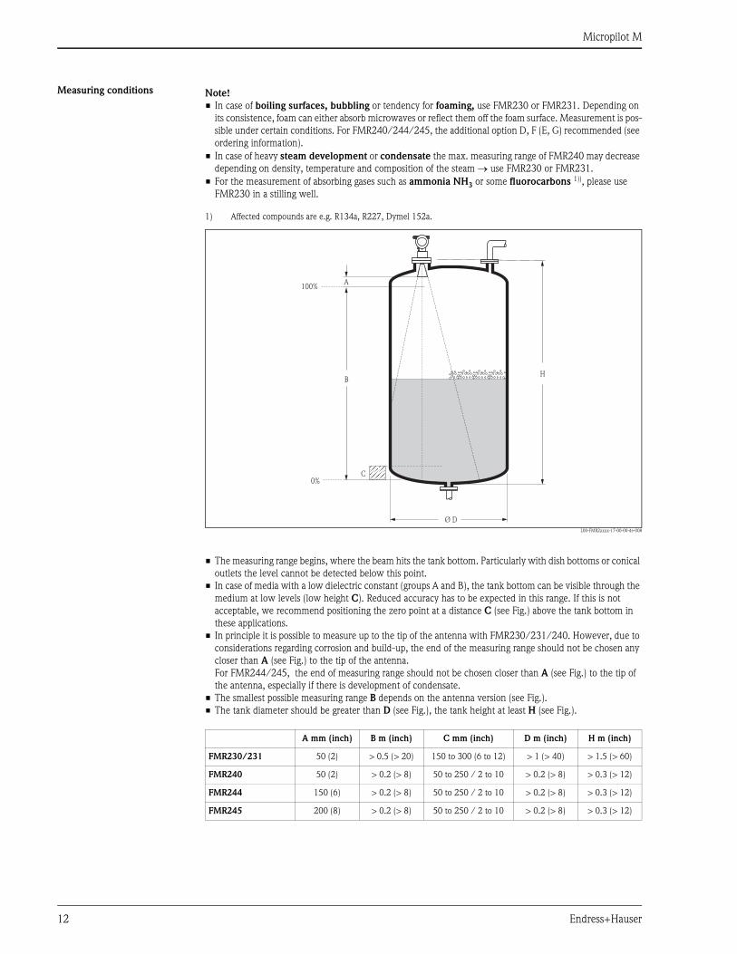
Measuring conditions
L00-FMR2xxxx-17-00-00-de-008
• The measuring range begins, where the beam hits the tank bottom. Particularly with dish bottoms or conical
outlets the level cannot be detected below this point.
• In case of media with a low dielectric constant (groups A and B), the tank bottom can be visible through the
medium at low levels (low height C). Reduced accuracy has to be expected in this range. If this is not
acceptable, we recommend positioning the zero point at a distance C (see Fig.) above the tank bottom in
these applications.
• In principle it is possible to measure up to the tip of the antenna with FMR230/231/240. However, due to
considerations regarding corrosion and build-up, the end of the measuring range should not be chosen any
closer than A (see Fig.) to the tip of the antenna.
For FMR244/245, the end of measuring range should not be chosen closer than A (see Fig.) to the tip of
the antenna, especially if there is development of condensate.
• The smallest possible measuring range B depends on the antenna version (see Fig.).
• The tank diameter should be greater than D (see Fig.), the tank height at least H (see Fig.).
Note!
• In case of boiling surfaces, bubbling or tendency for foaming, use FMR230 or FMR231. Depending on
its consistence, foam can either absorb microwaves or reflect them off the foam surface. Measurement is pos-
sible under certain conditions. For FMR240/244/245, the additional option D, F (E, G) recommended (see
ordering information).
• In case of heavy steam development or condensate the max. measuring range of FMR240 may decrease
depending on density, temperature and composition of the steam → use FMR230 or FMR231.
• For the measurement of absorbing gases such as ammonia NH3 or some fluorocarbons 1)), please use
FMR230 in a stilling well.
1) Affected compounds are e.g. R134a, R227, Dymel 152a.
100%
0%
B
A
C
H
Ø D
A mm (inch) B m (inch) C mm (inch) D m (inch) H m (inch)
FMR230/231 50 (2) > 0.5 (> 20) 150 to 300 (6 to 12) > 1 (> 40) > 1.5 (> 60)
FMR240 50 (2) > 0.2 (> 8) 50 to 250 / 2 to 10 > 0.2 (> 8) > 0.3 (> 12)
FMR244 150 (6) > 0.2 (> 8) 50 to 250 / 2 to 10 > 0.2 (> 8) > 0.3 (> 12)
FMR245 200 (8) > 0.2 (> 8) 50 to 250 / 2 to 10 > 0.2 (> 8) > 0.3 (> 12)
Micropilot M
Endress+Hauser 13
Operating frequency • FMR230/231: C-band
• FMR240/244/245: K-band
Up to 8 Micropilot M transmitters can be installed in the same tank because the transmitter pulses are
statistically coded.
Transmitting power Average energy density in beam direction:
Output
Output signal • 4 to 20 mA with HART protocol
• PROFIBUS PA
• FOUNDATION Fieldbus (FF)
Signal on alarm Error information can be accessed via the following interfaces:
• Local display:
– Error symbol
– Plain text display
• Current output, signal on error can be selected (e.g. according to NAMUR recommendation NE 43).
• Digital interface
Linearization The linearization function of the Micropilot M allows the conversion of the measured value into any unit of
length or volume. Linearization tables for calculating the volume in cylindrical tanks are pre-programmed.
Other tables of up to 32 value pairs can be entered manually or semi-automatically.
Distance Average energy density
1 m (3 ft) < 4 nW/cm2
5 m (16 ft) < 0.16 nW/cm2
Micropilot M
14 Endress+Hauser
Auxiliary energy
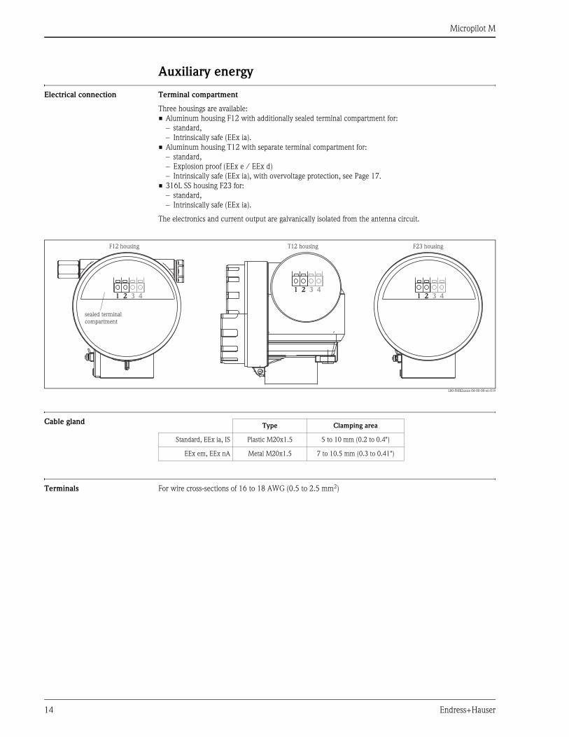
Electrical connection Terminal compartment
Three housings are available:
• Aluminum housing F12 with additionally sealed terminal compartment for:
– standard,
– Intrinsically safe (EEx ia).
• Aluminum housing T12 with separate terminal compartment for:
– standard,
– Explosion proof (EEx e / EEx d)
– Intrinsically safe (EEx ia), with overvoltage protection, see Page 17.
• 316L SS housing F23 for:
– standard,
– Intrinsically safe (EEx ia).
The electronics and current output are galvanically isolated from the antenna circuit.
L00-FMR2xxxx-04-00-00-en-019
Cable gland
Terminals For wire cross-sections of 16 to 18 AWG (0.5 to 2.5 mm2)
1 12 23 34 41 2 3 4
sealed terminalcompartment
F12 housing F23 housingT12 housing
Type Clamping area
Standard, EEx ia, IS Plastic M20x1.5 5 to 10 mm (0.2 to 0.4")
EEx em, EEx nA Metal M20x1.5 7 to 10.5 mm (0.3 to 0.41")
Micropilot M
Endress+Hauser 15
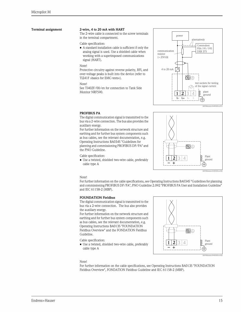
Terminal assignment 2-wire, 4 to 20 mA with HART
The 2-wire cable is connected to the screw terminals
in the terminal compartment.
Cable specification:
• A standard installation cable is sufficient if only the
analog signal is used. Use a shielded cable when
working with a superimposed communications
signal (HART).
Note!
Protective circuitry against reverse polarity, RFI, and
over-voltage peaks is built into the device (refer to
TI241F »basics for EMC-tests«).
Note!
See TI402F/00/en for connection to Tank Side
Monitor NRF590.
L00-FMxxxxxx-04-00-00-en-015
3 4I+ I-
1 2L- L+
4 to 20 mA
CommuboxFXA 191/195DXR 375communication
resistor
(> 250 )W
alternatively
plantground
test sockets for testingof the signal current
power
PROFIBUS PA
The digital communication signal is transmitted to the
bus via a 2-wire connection. The bus also provides the
auxiliary energy.
For further information on the network structure and
earthing and for further bus system components such
as bus cables, see the relevant documentation, e.g.
Operating Instructions BA034S "Guidelines for
planning and commissioning PROFIBUS DP/PA" and
the PNO Guideline.
Cable specification:
• Use a twisted, shielded two-wire cable, preferably
cable type A
L00-FMxxxxxx-04-00-00-en-022
Note!
For further information on the cable specifications, see Operating Instructions BA034S "Guidelines for planning
and commissioning PROFIBUS DP/PA", PNO Guideline 2.092 "PROFIBUS PA User and Installation Guideline"
and IEC 61158-2 (MBP).
3 41 2+–
Plantground
FOUNDATION Fieldbus
The digital communication signal is transmitted to the
bus via a 2-wire connection. The bus also provides
the auxiliary energy.
For further information on the network structure and
earthing and for further bus system components such
as bus cables, see the relevant documentation, e.g.
Operating Instructions BA013S "FOUNDATION
Fieldbus Overview" and the FONDATION Fieldbus
Guideline.
Cable specification:
• Use a twisted, shielded two-wire cable, preferably
cable type A
L00-FMxxxxxx-04-00-00-en-022
Note!
For further information on the cable specifications, see Operating Instructions BA013S "FOUNDATION
Fieldbus Overview", FONDATION Fieldbus Guideline and IEC 61158-2 (MBP).
3 41 2+–
Plantground
Micropilot M
16 Endress+Hauser
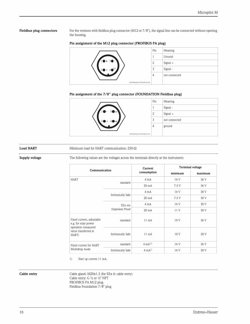
Fieldbus plug connectors For the versions with fieldbus plug connector (M12 or 7/8"), the signal line can be connected without opening
the housing.
Pin assignment of the M12 plug connector (PROFIBUS PA plug)
Pin assignment of the 7/8" plug connector (FOUNDATION Fieldbus plug)
Load HART Minimum load for HART communication: 250 Ω
Supply voltage The following values are the voltages across the terminals directly at the instrument:
Cable entry Cable gland: M20x1.5 (for EEx d: cable entry)
Cable entry: G ½ or ½" NPT
PROFIBUS PA M12 plug
Fieldbus Foundation 7/8" plug
L00-FMxxxxxx-04-00-00-yy-016
Pin Meaning
1 Ground
2 Signal +
3 Signal -
4 not connected
L00-FMxxxxxx-04-00-00-yy-017
Pin Meaning
1 Signal -
2 Signal +
3 not connected
4 ground
2
1 3
4+
-
nc
2
1 3
4+
- nc
CommunicationCurrent
consumption
Terminal voltage
minimum maximum
HARTstandard
4 mA 16 V 36 V
20 mA 7.5 V 36 V
Intrinsically Safe4 mA 16 V 30 V
20 mA 7.5 V 30 V
EEx em
Explosion Proof
4 mA 16 V 30 V
20 mA 11 V 30 V
Fixed current, adjustable
e.g. for solar power
operation (measured
value transferred at
HART)
standard 11 mA 10 V 36 V
Intrinsically Safe 11 mA 10 V 30 V
Fixed current for HART
Multidrop mode
standard 4 mA1))
1) Start up current 11 mA.
16 V 36 V
Intrinsically Safe 4 mA1) 16 V 30 V
Micropilot M
Endress+Hauser 17
Power consumption Minimum 60 mW, max. 900 mW
Current consumption
Ripple HART 47 to 125 Hz: Uss = 200 mV (at 500 Ω)
Max. noise HART 500 Hz to 10 kHz: Ueff = 2.2 mV (at 500 Ω)
Overvoltage protector The level transmitter Micropilot M with T12-housing (housing version "D", see ordering information on page
50-61) is equipped with an internal overvoltage protector (600 V surge arrester) according to
DIN EN 60079-14 or IEC 60060-1 (impulse current test 8/20 µs, Î = 10 kA, 10 pulses). Connect the metallic
housing of the Micropilot M to the tank wall or shield directly with an electrically conductive lead to ensure
reliable potential matching.
Communication Current consumption
HART 3.6 to 22 mA1))
1) for HART Multidrop: start up current is 11 mA.
PROFIBUS PA max. 13 mA
FOUNDATION Fieldbus max. 15 mA
Micropilot M
18 Endress+Hauser
Performance characteristics
Reference operating
conditions
• Temperatur = +20°C (68°F) ±5 °C (9°F)
• Pressure = 1013 mbar abs. (14.7 psia) ±20 mbar (0.3 psi)
• Relative humidity (air) = 65 % ±20%
• Ideal reflector
• No major interference reflections inside the signal beam
Maximum measured error Typical statements for reference conditions, include linearity, repeatability, and hysteresis:
FMR230, FMR231:
• To 10 m (33 ft): ± 10 mm (0.39")
• Over 10 m (33 ft): ± 0.1 % of measuring range
FMR240, FMR244, FMR245:
• Not for max. measuring range = 70 m (229 ft)
– To 1 m (3 ft): ± 10 mm (0.39")
• For max. measuring range = 20 m ( 65 ft) and 40 m (131 ft)
– To 10 m (33 ft): ± 3 mm (0.12")
– Over 10 m (33 ft): ± 0.03 % of measuring range, whatever is larger
• For max. measuring range = 70 m (229 ft)
– To 1 m (3 ft): ± 30 mm (1.18")
– Over 1 m (3 ft): ± 15 mm (0.59") or 0.04 % of measuring range, whatever is larger
Resolution Digital / analog in % 4 to 20 mA
• FMR230: 1 mm (0.04") / 0.03 % of measuring range
• FMR231: 1 mm (0.04") / 0.03 % of measuring range
• FMR240: 1 mm (0.04") / 0.03 % of measuring range
• FMR244: 1 mm (0.04") / 0.03 % of measuring range
• FMR245: 1 mm (0.04") / 0.03 % of measuring range
Reaction time The reaction time depends on the parameter settings (min. 1 s). In case of fast level changes, the instrument
needs the reaction time to indicate the new value.
Influence of ambient
temperature
The measurements are carried out in accordance with EN 61298-3:
• digital output (HART, PROFIBUS PA, FOUNDATION Fieldbus):
– FMR240
average TK: 2 mm/10 K (0.08"/10K), max. 5 mm (0.20") over the entire temperature
range -40 to +80°C (-40 to +176°F)
– FMR230
average TK: 3 mm/10 K (0.12"/10K), max. 10 mm (0.39") over the entire temperature
range -40 to +80°C (-40 to +176°F)
– FMR231
average TK: 5 mm/10 K (0.20"/10K), max. 15 mm (0.60") over the entire temperature
range -40 to +80°C (-40 to +176°F)
• Current output (additional error, in reference to the span of 16 mA):
– Zero point (4 mA)
average TK: 0.03 %/10 K, max. 0.45 % over the entire temperature
range -40 to +80°C (-40 to +176°F)
– Span (20 mA)
average TK: 0.09 %/10 K, max. 0.95 % over the entire temperature
range -40 to +80°C (-40 to +176°F)
Micropilot M
Endress+Hauser 19
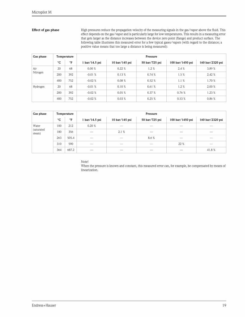
Effect of gas phase High pressures reduce the propagation velocity of the measuring signals in the gas/vapor above the fluid. This
effect depends on the gas/vapor and is particularly large for low temperatures. This results in a measuring error
that gets larger as the distance increases between the device zero point (flange) and product surface. The
following table illustrates this measured error for a few typical gases/vapors (with regard to the distance; a
positive value means that too large a distance is being measured):
Note!
When the pressure is known and constant, this measured error can, for example, be compensated by means of
linearization.
Gas phase Temperature Pressure
°C °F 1 bar/14.5 psi 10 bar/145 psi 50 bar/725 psi 100 bar/1450 psi 160 bar/2320 psi
Air
Nitrogen
20 68 0.00 % 0.22 % 1.2 % 2.4 % 3.89 %
200 392 -0.01 % 0.13 % 0.74 % 1.5 % 2.42 %
400 752 -0.02 % 0.08 % 0.52 % 1.1 % 1.70 %
Hydrogen 20 68 -0.01 % 0.10 % 0.61 % 1.2 % 2.00 %
200 392 -0.02 % 0.05 % 0.37 % 0.76 % 1.23 %
400 752 -0.02 % 0.03 % 0.25 % 0.53 % 0.86 %
Gas phase Temperature Pressure
°C °F 1 bar/14.5 psi 10 bar/145 psi 50 bar/725 psi 100 bar/1450 psi 160 bar/2320 psi
Water
(saturated
steam)
100 212 0.20 % — — — —
180 356 — 2.1 % — — —
263 505.4 — — 8.6 % — —
310 590 — — — 22 % —
364 687.2 — — — — 41.8 %
Micropilot M
20 Endress+Hauser
Operating conditions: Installation
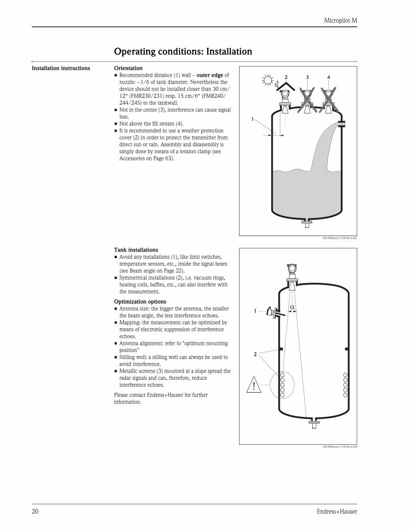
Installation instructions Orientation
• Recommended distance (1) wall – outer edge of
nozzle: ~1/6 of tank diameter. Nevertheless the
device should not be installed closer than 30 cm/
12“ (FMR230/231) resp. 15 cm/6“ (FMR240/
244/245) to the tankwall.
• Not in the center (3), interference can cause signal
loss.
• Not above the fill stream (4).
• It is recommended to use a weather protection
cover (2) in order to protect the transmitter from
direct sun or rain. Assembly and disassembly is
simply done by means of a tension clamp (see
Accessories on Page 63).
L00-FMR2xxxx-17-00-00-xx-001
1
2 3 4
Tank installations
• Avoid any installations (1), like limit switches,
temperature sensors, etc., inside the signal beam
(see Beam angle on Page 22).
• Symmetrical installations (2), i.e. vacuum rings,
heating coils, baffles, etc., can also interfere with
the measurement.
Optimization options
• Antenna size: the bigger the antenna, the smaller
the beam angle, the less interference echoes.
• Mapping: the measurement can be optimized by
means of electronic suppression of interference
echoes.
• Antenna alignment: refer to "optimum mounting
position"
• Stilling well: a stilling well can always be used to
avoid interference.
• Metallic screens (3) mounted at a slope spread the
radar signals and can, therefore, reduce
interference echoes.
Please contact Endress+Hauser for further
information.
L00-FMR2xxxx-17-00-00-xx-002
1
2
a
Micropilot M
Endress+Hauser 21
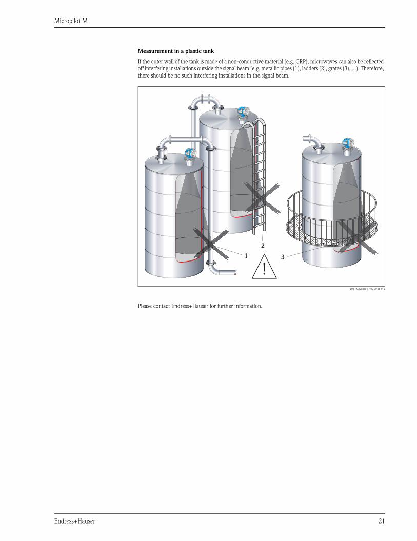
Measurement in a plastic tank
If the outer wall of the tank is made of a non-conductive material (e.g. GRP), microwaves can also be reflected
off interfering installations outside the signal beam (e.g. metallic pipes (1), ladders (2), grates (3), ...). Therefore,
there should be no such interfering installations in the signal beam.
L00-FMR2xxxx-17-00-00-xx-013
Please contact Endress+Hauser for further information.
VH
00
VH
00
Endress+Hauser
Endress+Hauser
- + V H
ENDRESS+HAUSERMICROPILOT II
IP 65
Order Code:Ser.-No.:
MessbereichMeasuring rangeU 16...36 V DC4...20 mA
max. 20 m
Mad
e in
Ger
man
y
M
aulb
urg
Mad
e in
Ger
man
y
M
aulb
urg
T >70°C :At >85°C
VH
00
VH
00
Endress+Hauser
Endress+Hauser
- + V H
ENDRESS+HAUSERMICROPILOT II
IP 65
Order Code:Ser.-No.:
MessbereichMeasuring rangeU 16...36 V DC4...20 mA
max. 20 m
Mad
e in
Ger
man
y
M
aulb
urg
Mad
e in
Ger
man
y
M
aulb
urg
T >70°C :At >85°C
VH
00
VH
00
Endress+Hauser
Endress+Hauser
- + V H
ENDRESS+HAUSERMICROPILOT II
IP 65
Order Code:Ser.-No.:
MessbereichMeasuring rangeU 16...36 V DC4...20 mA
max. 20 m
Mad
e in
Ger
man
y
M
aulb
urg
Mad
e in
Ger
man
y
M
aulb
urg
T >70°C :At >85°C
1
2
3
Micropilot M
22 Endress+Hauser
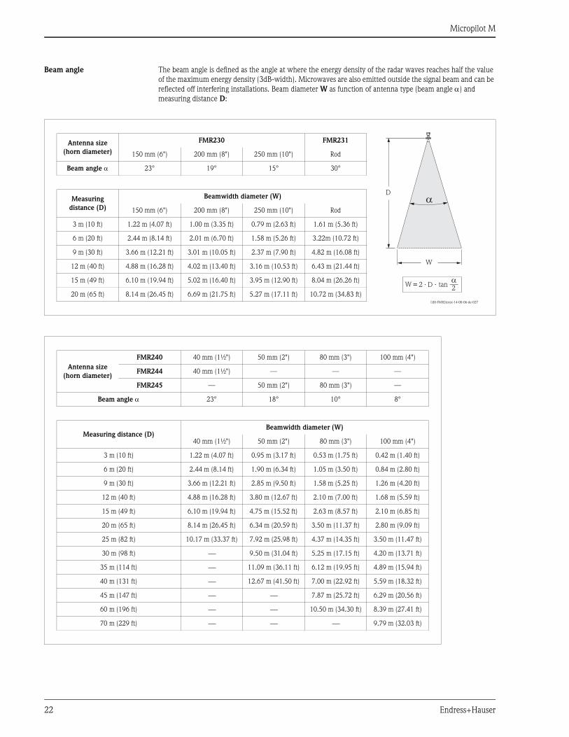
Beam angle The beam angle is defined as the angle at where the energy density of the radar waves reaches half the value
of the maximum energy density (3dB-width). Microwaves are also emitted outside the signal beam and can be
reflected off interfering installations. Beam diameter W as function of antenna type (beam angle α) and
measuring distance D:
L00-FMR2xxxx-14-00-06-de-027
Antenna size
(horn diameter)
FMR230 FMR231
150 mm (6") 200 mm (8") 250 mm (10") Rod
Beam angle α 23° 19° 15° 30°
Measuring
distance (D)
Beamwidth diameter (W)
150 mm (6") 200 mm (8") 250 mm (10") Rod
3 m (10 ft) 1.22 m (4.07 ft) 1.00 m (3.35 ft) 0.79 m (2.63 ft) 1.61 m (5.36 ft)
6 m (20 ft) 2.44 m (8.14 ft) 2.01 m (6.70 ft) 1.58 m (5.26 ft) 3.22m (10.72 ft)
9 m (30 ft) 3.66 m (12.21 ft) 3.01 m (10.05 ft) 2.37 m (7.90 ft) 4.82 m (16.08 ft)
12 m (40 ft) 4.88 m (16.28 ft) 4.02 m (13.40 ft) 3.16 m (10.53 ft) 6.43 m (21.44 ft)
15 m (49 ft) 6.10 m (19.94 ft) 5.02 m (16.40 ft) 3.95 m (12.90 ft) 8.04 m (26.26 ft)
20 m (65 ft) 8.14 m (26.45 ft) 6.69 m (21.75 ft) 5.27 m (17.11 ft) 10.72 m (34.83 ft)
aD
W
aD _=
22 . . tanW
Antenna size
(horn diameter)
FMR240 40 mm (1½") 50 mm (2") 80 mm (3") 100 mm (4")
FMR244 40 mm (1½") — — —
FMR245 — 50 mm (2") 80 mm (3") —
Beam angle α 23° 18° 10° 8°
Measuring distance (D)Beamwidth diameter (W)
40 mm (1½") 50 mm (2") 80 mm (3") 100 mm (4")
3 m (10 ft) 1.22 m (4.07 ft) 0.95 m (3.17 ft) 0.53 m (1.75 ft) 0.42 m (1.40 ft)
6 m (20 ft) 2.44 m (8.14 ft) 1.90 m (6.34 ft) 1.05 m (3.50 ft) 0.84 m (2.80 ft)
9 m (30 ft) 3.66 m (12.21 ft) 2.85 m (9.50 ft) 1.58 m (5.25 ft) 1.26 m (4.20 ft)
12 m (40 ft) 4.88 m (16.28 ft) 3.80 m (12.67 ft) 2.10 m (7.00 ft) 1.68 m (5.59 ft)
15 m (49 ft) 6.10 m (19.94 ft) 4.75 m (15.52 ft) 2.63 m (8.57 ft) 2.10 m (6.85 ft)
20 m (65 ft) 8.14 m (26.45 ft) 6.34 m (20.59 ft) 3.50 m (11.37 ft) 2.80 m (9.09 ft)
25 m (82 ft) 10.17 m (33.37 ft) 7.92 m (25.98 ft) 4.37 m (14.35 ft) 3.50 m (11.47 ft)
30 m (98 ft) ⎯ 9.50 m (31.04 ft) 5.25 m (17.15 ft) 4.20 m (13.71 ft)
35 m (114 ft) ⎯ 11.09 m (36.11 ft) 6.12 m (19.95 ft) 4.89 m (15.94 ft)
40 m (131 ft) ⎯ 12.67 m (41.50 ft) 7.00 m (22.92 ft) 5.59 m (18.32 ft)
45 m (147 ft) ⎯ ⎯ 7.87 m (25.72 ft) 6.29 m (20.56 ft)
60 m (196 ft) ⎯ ⎯ 10.50 m (34.30 ft) 8.39 m (27.41 ft)
70 m (229 ft) ⎯ ⎯ ⎯ 9.79 m (32.03 ft)

Micropilot M
Endress+Hauser 23
Installation in tank
(free space) FMR230
Optimum mounting position
L00-FMR230xx-17-00-00-en-001
90°
90°
90°
90°
90°
90°
90°
90°
90°
90°
9
6” ANSIDN 150
8 to 10” ANSIDN 200 to 250
Marker at instrument flange
Standard installation
• Observe installation instructions on Page 20.
• Marker is aligned towards tank wall.
• The marker is always exactly in the middle
between two bolt-holes in the flange.
• After mounting, the housing can be turned 350° in
order to simplify access to the display and the
terminal compartment.
• The horn antenna must extend below the nozzle,
otherwise use antenna extension FAR10.
• Align horn antenna vertically.
L00-FMR230xx-17-00-00-en-002
H
Ø D
Nozzlenozzle
Antenna size 150 mm / 6" 200 mm / 8" 250 mm / 10"
D [mm / inch] 146 / 5.8 191 / 7.5 241 / 9.5
H [mm / inch] < 205 / < 8.1 < 290 / < 11.5 < 380 / <15
Micropilot M
24 Endress+Hauser
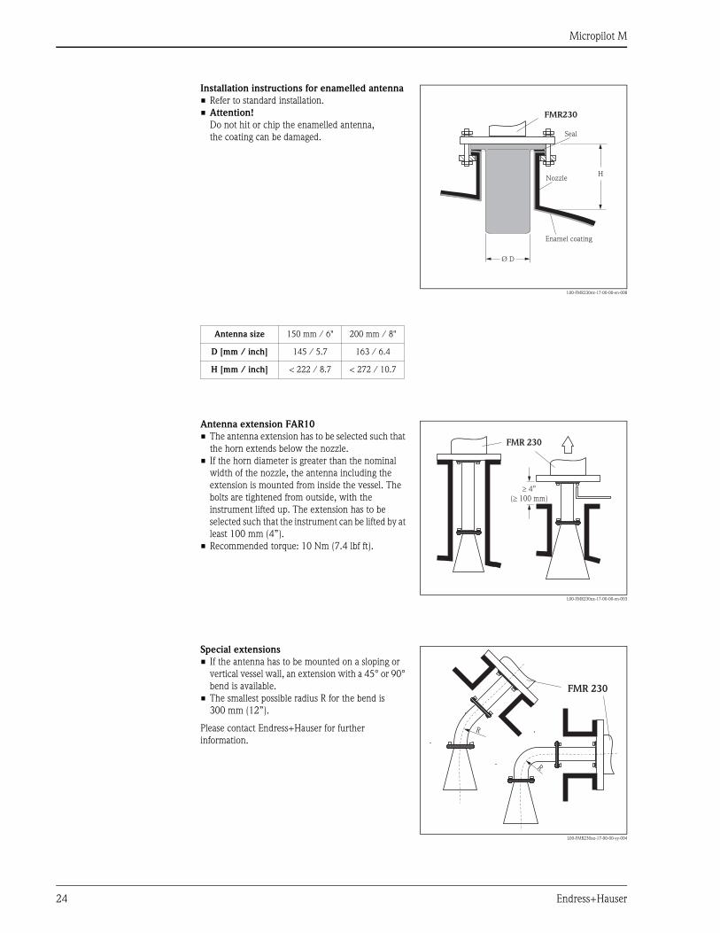
Installation instructions for enamelled antenna
• Refer to standard installation.
• Attention!
Do not hit or chip the enamelled antenna,
the coating can be damaged.
L00-FMR230xx-17-00-00-en-008
H
Ø D
Nozzle
Enamel coating
Seal
FMR230
Antenna size 150 mm / 6" 200 mm / 8"
D [mm / inch] 145 / 5.7 163 / 6.4
H [mm / inch] < 222 / 8.7 < 272 / 10.7
Antenna extension FAR10
• The antenna extension has to be selected such that
the horn extends below the nozzle.
• If the horn diameter is greater than the nominal
width of the nozzle, the antenna including the
extension is mounted from inside the vessel. The
bolts are tightened from outside, with the
instrument lifted up. The extension has to be
selected such that the instrument can be lifted by at
least 100 mm (4”).
• Recommended torque: 10 Nm (7.4 lbf ft).
L00-FMR230xx-17-00-00-en-003
4”
(³ 100 mm)
FMR 230
Special extensions
• If the antenna has to be mounted on a sloping or
vertical vessel wall, an extension with a 45° or 90°
bend is available.
• The smallest possible radius R for the bend is
300 mm (12”).
Please contact Endress+Hauser for further
information.
L00-FMR230xx-17-00-00-yy-004
R
R
FMR 230
Micropilot M
Endress+Hauser 25
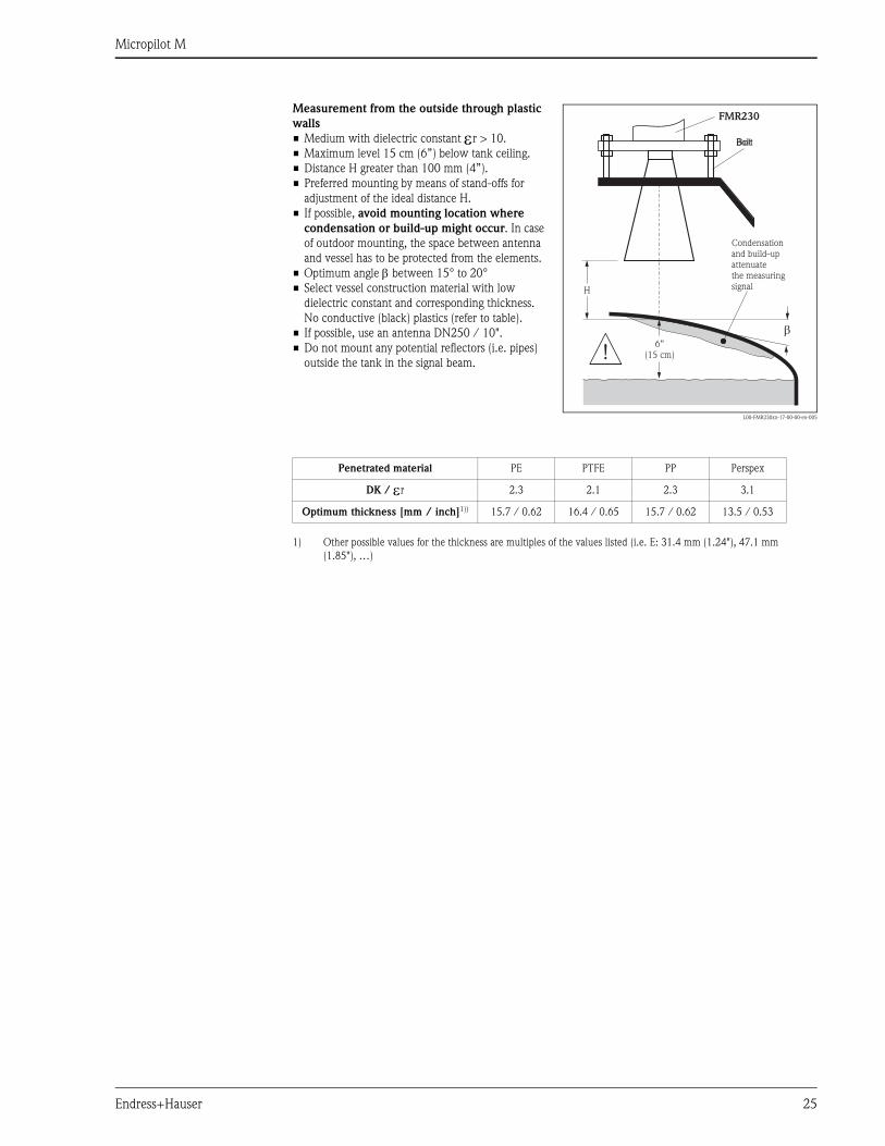
Measurement from the outside through plastic
walls
• Medium with dielectric constant εr > 10.
• Maximum level 15 cm (6”) below tank ceiling.
• Distance H greater than 100 mm (4”).
• Preferred mounting by means of stand-offs for
adjustment of the ideal distance H.
• If possible, avoid mounting location where
condensation or build-up might occur. In case
of outdoor mounting, the space between antenna
and vessel has to be protected from the elements.
• Optimum angle β between 15° to 20°
• Select vessel construction material with low
dielectric constant and corresponding thickness.
No conductive (black) plastics (refer to table).
• If possible, use an antenna DN250 / 10".
• Do not mount any potential reflectors (i.e. pipes)
outside the tank in the signal beam.
L00-FMR230xx-17-00-00-en-005
b
H
6”(15 cm)
BoltBolt
FMR230
Condensationand build-upattenuatethe measuringsignal
Penetrated material PE PTFE PP Perspex
DK / εr 2.3 2.1 2.3 3.1
Optimum thickness [mm / inch]1))
1) Other possible values for the thickness are multiples of the values listed (i.e. E: 31.4 mm (1.24"), 47.1 mm
(1.85"), …)
15.7 / 0.62 16.4 / 0.65 15.7 / 0.62 13.5 / 0.53
Micropilot M
26 Endress+Hauser
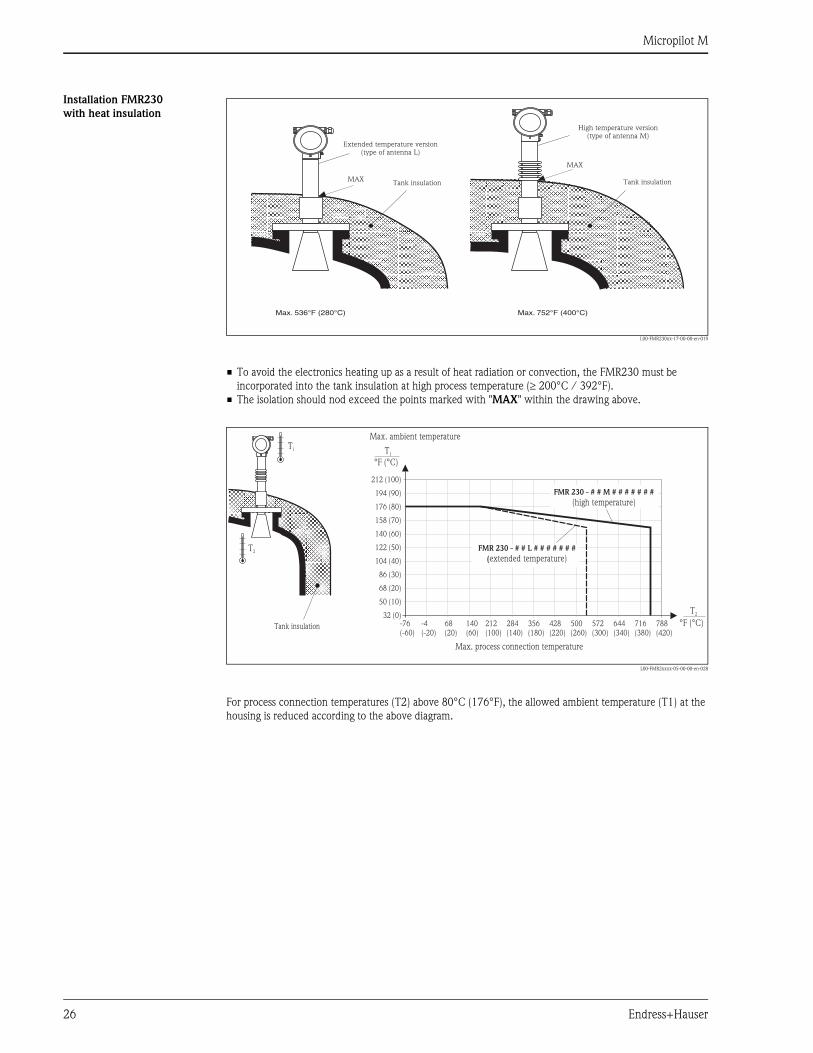
Installation FMR230
with heat insulation
L00-FMR230xx-17-00-00-en-019
• To avoid the electronics heating up as a result of heat radiation or convection, the FMR230 must be
incorporated into the tank insulation at high process temperature (≥ 200°C / 392°F).
• The isolation should nod exceed the points marked with "MAX" within the drawing above.
L00-FMR2xxxx-05-00-00-en-028
For process connection temperatures (T2) above 80°C (176°F), the allowed ambient temperature (T1) at the
housing is reduced according to the above diagram.
MAX
MAX
Max. (400°C)752°FMax. 280°C)536°F (
Tank insulationTank insulation
High temperature version(type of antenna M)
Extended temperature version(type of antenna L)
T2
T1
Tank insulation -76(-60)
32 (0)
50 (10)
68 (20)
86 (30)
104 (40)
122 (50)
140 (60)
158 (70)
176 (80)
194 (90)
212 (100)
-4(-20)
68(20)
140(60)
212(100)
284(140)
356(180)
428(220)
500(260)
572(300)
644(340)
716(380)
788(420)
T1
°F (°C)
°F (°C)
T2
FMR 230 - # # M # # # # # # #
(high temperature)
Max. ambient temperature
Max. process connection temperature
FMR 230 - # # L # # # # # # #
(extended temperature)
Micropilot M
Endress+Hauser 27
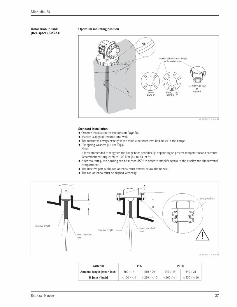
Installation in tank
(free space) FMR231
Optimum mounting position
L00-FMR231xx-17-00-00-en-001
Standard installation
• Observe installation instructions on Page 20.
• Marker is aligned towards tank wall.
• The marker is always exactly in the middle between two bolt-holes in the flange.
• Use spring washers (1) (see Fig.).
Note!
It is recommended to retighten the flange bolts periodically, depending on process temperature and pressure.
Recommended torque: 60 to 100 Nm (44 to 74 lbf ft).
• After mounting, the housing can be turned 350° in order to simplify access to the display and the terminal
compartment.
• The inactive part of the rod antenna must extend below the nozzle.
• The rod antenna must be aligned vertically.
L00-FMR231xx-17-00-00-en-002
HH
1
beam launchedhere
beam launchedhere
inactive length
inactive length
spring washers
Material PPS PTFE
Antenna length [mm / inch] 360 / 14 510 / 20 390 / 15 540 / 21
H [mm / inch] < 100 / < 4 < 250 / < 10 < 100 / < 4 < 250 / < 10
Micropilot M
28 Endress+Hauser
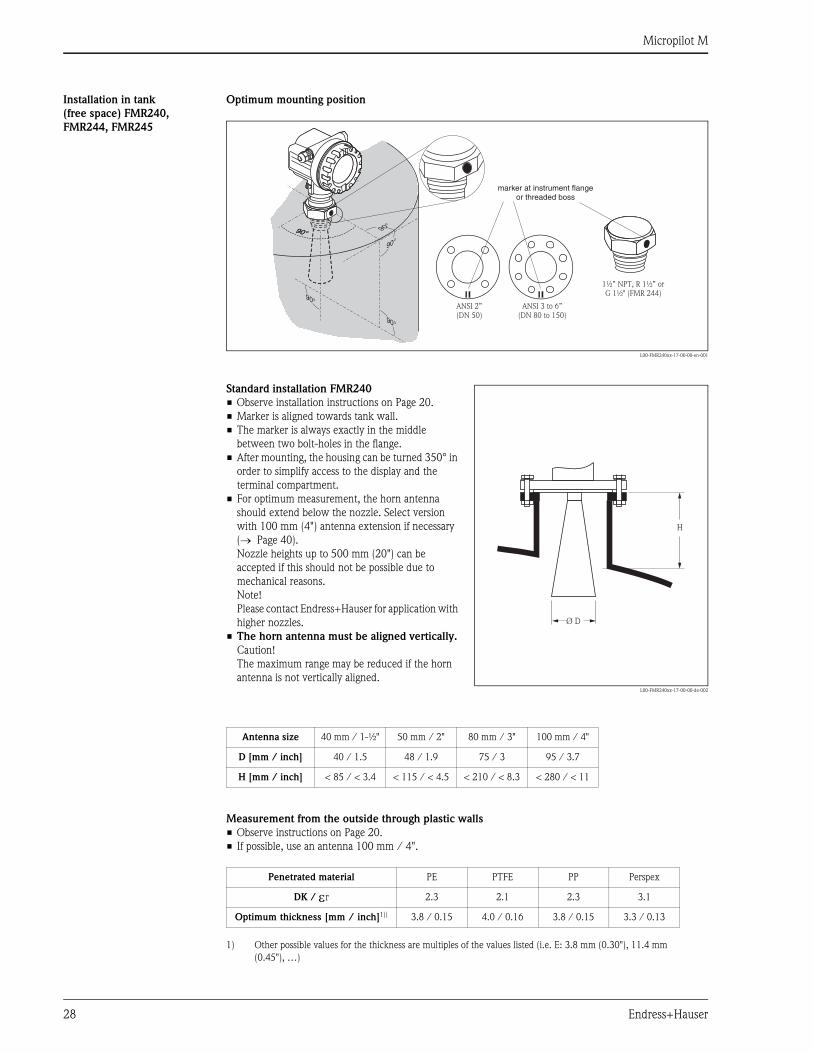
Installation in tank
(free space) FMR240,
FMR244, FMR245
Optimum mounting position
L00-FMR240xx-17-00-00-en-001
Measurement from the outside through plastic walls
• Observe instructions on Page 20.
• If possible, use an antenna 100 mm / 4".
90°
90°
90°
90°
90°
90°
90°
90°
9
ANSI 3 to 6”(DN 80 to 150)
ANSI 2”(DN 50)
90°90°
1½” NPT, R 1½” orG 1½" (FMR 244)
marker at instrument flangeor threaded boss
Standard installation FMR240
• Observe installation instructions on Page 20.
• Marker is aligned towards tank wall.
• The marker is always exactly in the middle
between two bolt-holes in the flange.
• After mounting, the housing can be turned 350° in
order to simplify access to the display and the
terminal compartment.
• For optimum measurement, the horn antenna
should extend below the nozzle. Select version
with 100 mm (4") antenna extension if necessary
(→ Page 40).
Nozzle heights up to 500 mm (20") can be
accepted if this should not be possible due to
mechanical reasons.
Note!
Please contact Endress+Hauser for application with
higher nozzles.
• The horn antenna must be aligned vertically.
Caution!
The maximum range may be reduced if the horn
antenna is not vertically aligned.L00-FMR240xx-17-00-00-de-002
H
Ø D
Antenna size 40 mm / 1-½" 50 mm / 2" 80 mm / 3" 100 mm / 4"
D [mm / inch] 40 / 1.5 48 / 1.9 75 / 3 95 / 3.7
H [mm / inch] < 85 / < 3.4 < 115 / < 4.5 < 210 / < 8.3 < 280 / < 11
Penetrated material PE PTFE PP Perspex
DK / εr 2.3 2.1 2.3 3.1
Optimum thickness [mm / inch]1))
1) Other possible values for the thickness are multiples of the values listed (i.e. E: 3.8 mm (0.30"), 11.4 mm
(0.45"), …)
3.8 / 0.15 4.0 / 0.16 3.8 / 0.15 3.3 / 0.13
Micropilot M
Endress+Hauser 29
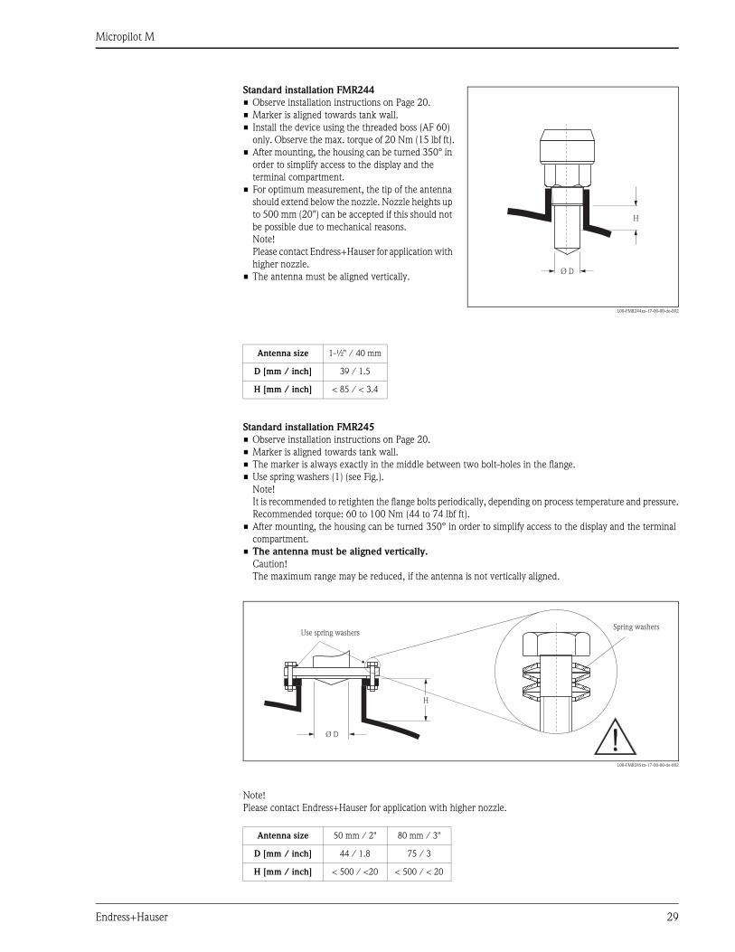
Standard installation FMR245
• Observe installation instructions on Page 20.
• Marker is aligned towards tank wall.
• The marker is always exactly in the middle between two bolt-holes in the flange.
• Use spring washers (1) (see Fig.).
Note!
It is recommended to retighten the flange bolts periodically, depending on process temperature and pressure.
Recommended torque: 60 to 100 Nm (44 to 74 lbf ft).
• After mounting, the housing can be turned 350° in order to simplify access to the display and the terminal
compartment.
• The antenna must be aligned vertically.
Caution!
The maximum range may be reduced, if the antenna is not vertically aligned.
L00-FMR245xx-17-00-00-de-002
Note!
Please contact Endress+Hauser for application with higher nozzle.
Standard installation FMR244
• Observe installation instructions on Page 20.
• Marker is aligned towards tank wall.
• Install the device using the threaded boss (AF 60)
only. Observe the max. torque of 20 Nm (15 lbf ft).
• After mounting, the housing can be turned 350° in
order to simplify access to the display and the
terminal compartment.
• For optimum measurement, the tip of the antenna
should extend below the nozzle. Nozzle heights up
to 500 mm (20") can be accepted if this should not
be possible due to mechanical reasons.
Note!
Please contact Endress+Hauser for application with
higher nozzle.
• The antenna must be aligned vertically.
L00-FMR244xx-17-00-00-de-002
H
Ø D
Antenna size 1-½" / 40 mm
D [mm / inch] 39 / 1.5
H [mm / inch] < 85 / < 3.4
Antenna size 50 mm / 2" 80 mm / 3"
D [mm / inch] 44 / 1.8 75 / 3
H [mm / inch] < 500 / <20 < 500 / < 20
Spring washers
H
Use spring washers
Ø D
Micropilot M
30 Endress+Hauser
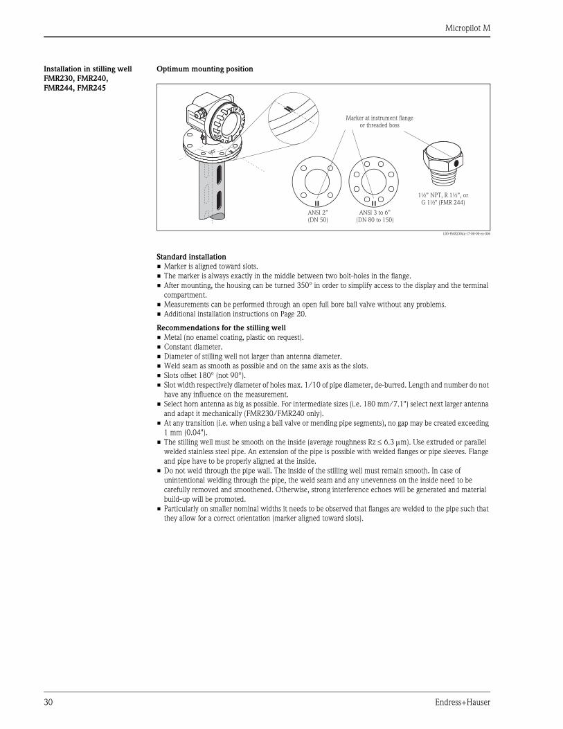
Installation in stilling well
FMR230, FMR240,
FMR244, FMR245
Optimum mounting position
L00-FMR230xx-17-00-00-en-006
Standard installation
• Marker is aligned toward slots.
• The marker is always exactly in the middle between two bolt-holes in the flange.
• After mounting, the housing can be turned 350° in order to simplify access to the display and the terminal
compartment.
• Measurements can be performed through an open full bore ball valve without any problems.
• Additional installation instructions on Page 20.
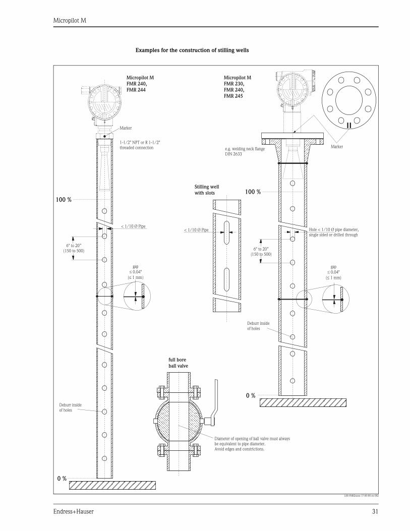
Recommendations for the stilling well
• Metal (no enamel coating, plastic on request).
• Constant diameter.
• Diameter of stilling well not larger than antenna diameter.
• Weld seam as smooth as possible and on the same axis as the slots.
• Slots offset 180° (not 90°).
• Slot width respectively diameter of holes max. 1/10 of pipe diameter, de-burred. Length and number do not
have any influence on the measurement.
• Select horn antenna as big as possible. For intermediate sizes (i.e. 180 mm/7.1") select next larger antenna
and adapt it mechanically (FMR230/FMR240 only).
• At any transition (i.e. when using a ball valve or mending pipe segments), no gap may be created exceeding
1 mm (0.04").
• The stilling well must be smooth on the inside (average roughness Rz ≤ 6.3 µm). Use extruded or parallel
welded stainless steel pipe. An extension of the pipe is possible with welded flanges or pipe sleeves. Flange
and pipe have to be properly aligned at the inside.
• Do not weld through the pipe wall. The inside of the stilling well must remain smooth. In case of
unintentional welding through the pipe, the weld seam and any unevenness on the inside need to be
carefully removed and smoothened. Otherwise, strong interference echoes will be generated and material
build-up will be promoted.
• Particularly on smaller nominal widths it needs to be observed that flanges are welded to the pipe such that
they allow for a correct orientation (marker aligned toward slots).
90°
ANSI 3 to 6”(DN 80 to 150)
ANSI 2”(DN 50)
Marker at instrument flangeor threaded boss
1½” NPT, R 1½”, orG 1½" (FMR 244)
Micropilot M
Endress+Hauser 31
Examples for the construction of stilling wells
L00-FMR2xxxx-17-00-00-en-002
100 %
0 %
6" to 20”(150 to 500) 6" to 20”
(150 to 500)
100 %
0 %
Micropilot M
FMR 230,
FMR 240,
FMR 245
Micropilot M
FMR 240,
FMR 244
gap
0.04"
( 1 mm)
gap
0.04"
( 1 mm)
1-1/2" NPT or R 1-1/2"threaded connection
Marker
Deburr insideof holes
Deburr insideof holes
< 1/10 Ø Pipe
Stilling well
with slots
Hole < 1/10 Ø pipe diameter,single sided or drilled through
Markere.g. welding neck flangeDIN 2633
< 1/10 Ø Pipe
full bore
ball valve
Diameter of o of ball valve must alwaysbe equivalent to pipe diameter.Avoid edges and constrictions.
pening
Micropilot M
32 Endress+Hauser
Installation in bypass
FMR230, FMR240, FMR245
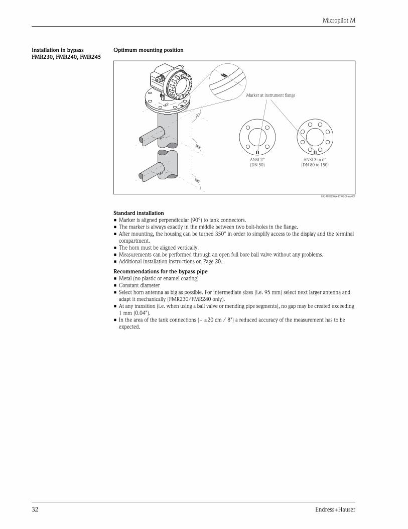
Optimum mounting position
L00-FMR230xx-17-00-00-en-007
Standard installation
• Marker is aligned perpendicular (90°) to tank connectors.
• The marker is always exactly in the middle between two bolt-holes in the flange.
• After mounting, the housing can be turned 350° in order to simplify access to the display and the terminal
compartment.
• The horn must be aligned vertically.
• Measurements can be performed through an open full bore ball valve without any problems.
• Additional installation instructions on Page 20.
Recommendations for the bypass pipe
• Metal (no plastic or enamel coating)
• Constant diameter
• Select horn antenna as big as possible. For intermediate sizes (i.e. 95 mm) select next larger antenna and
adapt it mechanically (FMR230/FMR240 only).
• At any transition (i.e. when using a ball valve or mending pipe segments), no gap may be created exceeding
1 mm (0.04").
• In the area of the tank connections (~ ±20 cm / 8") a reduced accuracy of the measurement has to be
expected.
90°
90°
90°
90°
90°
90°
ANSI 2”(DN 50)
ANSI 3 to 6”(DN 80 to 150)
Marker at instrument flange
Micropilot M
Endress+Hauser 33
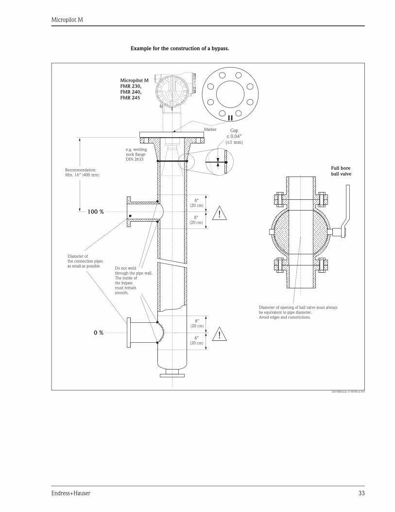
Example for the construction of a bypass.
L00-FMR2xxxx-17-00-00-en-019
100 %
0 %
Micropilot M
FMR 230,
FMR 240,
FMR 245
Full bore
ball valve
e.g. weldingneck flangeDIN 2633
Recommendation:Min. 16” (400 mm)
Diameter of o of ball valve must alwaysbe equivalent to pipe diameter.Avoid edges and constrictions.
pening
Do not weldthrough the pipe wall.The inside ofthe bypassmust remainsmooth.
Diameter ofthe connection pipesas small as possible
8”(20 cm)
Gap
0.04”
( 1 mm)
£
£
8”(20 cm)
8”(20 cm)
8”(20 cm)
Marker
Micropilot M
34 Endress+Hauser
Operating conditions: Environment
Ambient temperature range Ambient temperature for the transmitter: -40°C to +80°C (-40°F to +176°F), -50°C (-58°F) on request.
The functionality of the LCD display may be limited for temperatures Ta<-20°C (-68°F) and Ta>+60°C
(+68°F).
A weather protection cover should be used for outdoor operation if the instrument is exposed to direct sunlight.
Storage temperature -40°C to +80°C (-40°F to +176°F), -50°C (-58°F) on request.
Climate class DIN EN 60068-2-38 (test Z/AD)
Degree of protection • With closed housing: IP65, NEMA4X
• With open housing: IP20, NEMA1 (also ingress protection of the display)
• Antenna: IP68 (NEMA6P)
Vibration resistance DIN EN 60068-2-64 / IEC 68-2-64: 20 to 2000 Hz, 1 (m/s2)2/Hz
Cleaning of the antenna The antenna can get contaminated, depending on the application. The emission and reception of microwaves
can thus eventually be hindered. The degree of contamination leading to an error depends on the medium and
the reflectivity, mainly determined by the dielectric constant εr. If the medium tends to cause contamination
and deposits, cleaning on a regular basis is recommended. Care has to be taken not to damage the antenna in
the process of a mechanical or hose-down cleaning (eventually connection for cleaning liquid). The material
compatibility has to be considered if cleaning agents are used!
The maximum permitted temperature at the flange should not be exceeded.
Electromagnetic compatibility • Interference Emission to EN 61326, Electrical Equipment Class B
• Interference Immunity to EN 61326, Annex A (Industrial) and NAMUR Recommendation NE 21 (EMC)
• A standard installation cable is sufficient if only the analog signal is used. Use a shielded cable when working
with a superimposed communications signal (HART).
Micropilot M
Endress+Hauser 35
Operating conditions: Process
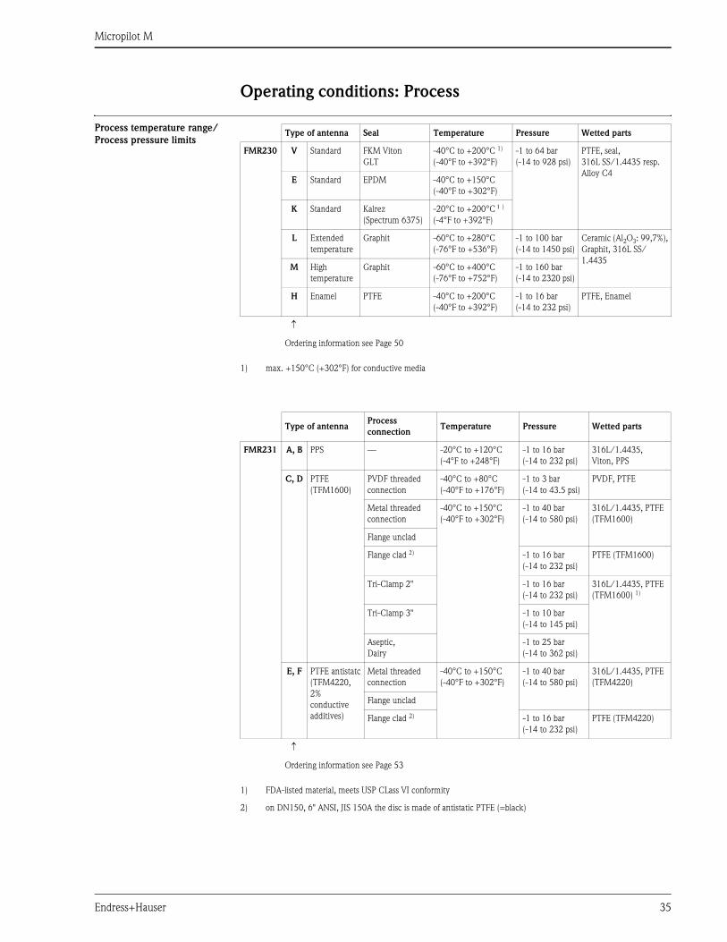
Process temperature range/
Process pressure limitsType of antenna Seal Temperature Pressure Wetted parts
FMR230 V Standard FKM Viton
GLT
-40°C to +200°C 1)
(-40°F to +392°F)
1) max. +150°C (+302°F) for conductive media
-1 to 64 bar
(-14 to 928 psi)
PTFE, seal,
316L SS/1.4435 resp.
Alloy C4E Standard EPDM -40°C to +150°C
(-40°F to +302°F)
K Standard Kalrez
(Spectrum 6375)
-20°C to +200°C 1 )
(-4°F to +392°F)
L Extended
temperature
Graphit -60°C to +280°C
(-76°F to +536°F)
-1 to 100 bar
(-14 to 1450 psi)
Ceramic (Al2O3: 99,7%),
Graphit, 316L SS/
1.4435M High
temperature
Graphit -60°C to +400°C
(-76°F to +752°F)
-1 to 160 bar
(-14 to 2320 psi)
H Enamel PTFE -40°C to +200°C
(-40°F to +392°F)
-1 to 16 bar
(-14 to 232 psi)
PTFE, Enamel
↑
Ordering information see Page 50
Type of antennaProcess
connectionTemperature Pressure Wetted parts
FMR231 A, B PPS — -20°C to +120°C
(-4°F to +248°F)
-1 to 16 bar
(-14 to 232 psi)
316L/1.4435,
Viton, PPS
C, D PTFE
(TFM1600)
PVDF threaded
connection
-40°C to +80°C
(-40°F to +176°F)
-1 to 3 bar
(-14 to 43.5 psi)
PVDF, PTFE
Metal threaded
connection
-40°C to +150°C
(-40°F to +302°F)
-1 to 40 bar
(-14 to 580 psi)
316L/1.4435, PTFE
(TFM1600)
Flange unclad
Flange clad 2) -1 to 16 bar
(-14 to 232 psi)
PTFE (TFM1600)
Tri-Clamp 2" -1 to 16 bar
(-14 to 232 psi)
316L/1.4435, PTFE
(TFM1600) 1)
1) FDA-listed material, meets USP CLass VI conformity
Tri-Clamp 3" -1 to 10 bar
(-14 to 145 psi)
Aseptic,
Dairy
-1 to 25 bar
(-14 to 362 psi)
E, F PTFE antistatc
(TFM4220,
2%
conductive
additives)
Metal threaded
connection
-40°C to +150°C
(-40°F to +302°F)
-1 to 40 bar
(-14 to 580 psi)
316L/1.4435, PTFE
(TFM4220)
Flange unclad
Flange clad 2)
2) on DN150, 6" ANSI, JIS 150A the disc is made of antistatic PTFE (=black)
-1 to 16 bar
(-14 to 232 psi)
PTFE (TFM4220)
↑
Ordering information see Page 53
Micropilot M
36 Endress+Hauser
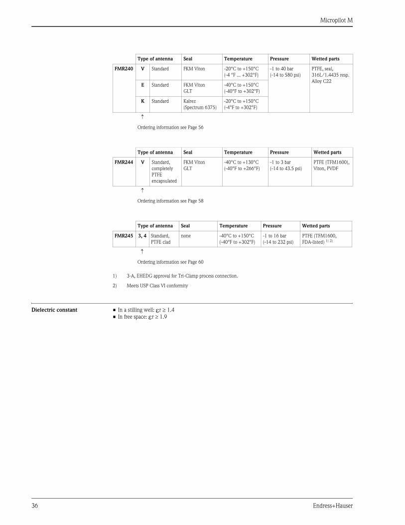
Dielectric constant • In a stilling well: εr ≥ 1.4
• In free space: εr ≥ 1.9
Type of antenna Seal Temperature Pressure Wetted parts
FMR240 V Standard FKM Viton -20°C to +150°C
(-4 °F ... +302°F)
-1 to 40 bar
(-14 to 580 psi)
PTFE, seal,
316L/1.4435 resp.
Alloy C22E Standard FKM Viton
GLT
-40°C to +150°C
(-40°F to +302°F)
K Standard Kalrez
(Spectrum 6375)
-20°C to +150°C
(-4°F to +302°F)
↑
Ordering information see Page 56
Type of antenna Seal Temperature Pressure Wetted parts
FMR244 V Standard,
completely
PTFE
encapsulated
FKM Viton
GLT
-40°C to +130°C
(-40°F to +266°F)
-1 to 3 bar
(-14 to 43.5 psi)
PTFE (TFM1600),
Viton, PVDF
↑
Ordering information see Page 58
Type of antenna Seal Temperature Pressure Wetted parts
FMR245 3, 4 Standard,
PTFE clad
none -40°C to +150°C
(-40°F to +302°F)
-1 to 16 bar
(-14 to 232 psi)
PTFE (TFM1600,
FDA-listed) 1) 2)
1) 3-A, EHEDG approval for Tri-Clamp process connection.
2) Meets USP Class VI conformity
↑
Ordering information see Page 60
Micropilot M
Endress+Hauser 37
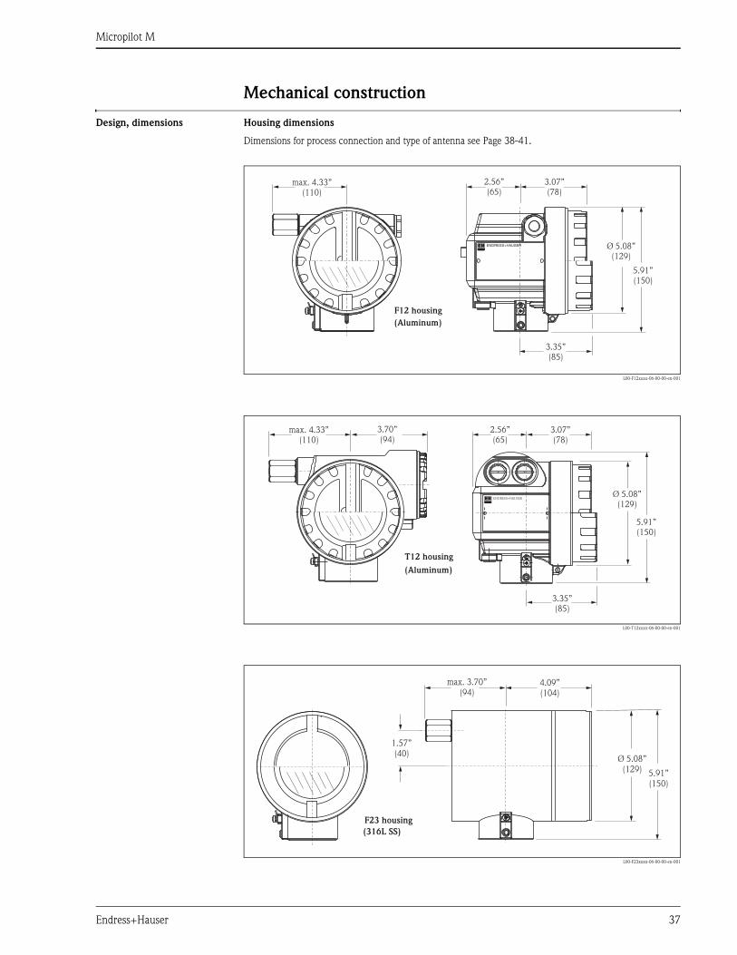
Mechanical construction
Design, dimensions Housing dimensions
Dimensions for process connection and type of antenna see Page 38-41.
L00-F12xxxx-06-00-00-en-001
L00-T12xxxx-06-00-00-en-001
L00-F23xxxx-06-00-00-en-001
ENDRESS+HAUSER
2.56”(65)
3.07”(78)
max. 4.33”(110)
3.35”(85)
5.91”(150)
Ø 5.08”(129)
(Aluminum)
F12 housing
ENDRESS+HAUSER
3.70”(94)
(Aluminum)
T12 housing
2.56”(65)
3.07”(78)
max. 4.33”(110)
3.35”(85)
5.91”(150)
Ø 5.08”(129)
max. 3.70”(94)
4.09”(104)
Ø 5.08”(129) 5.91”
(150)
1.57”(40)
(316L SS)
F23 housing
Micropilot M
38 Endress+Hauser
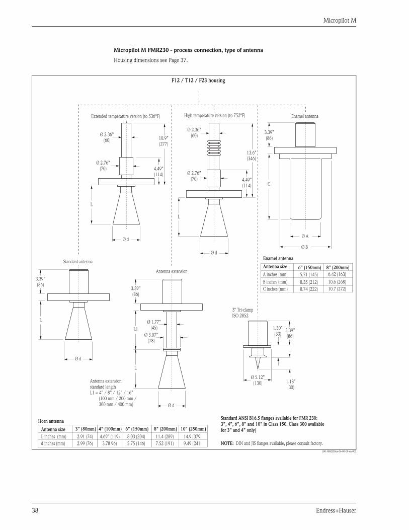
Micropilot M FMR230 - process connection, type of antenna
Housing dimensions see Page 37.
L00-FMR230xx-06-00-00-en-005
13.6”(346)
10.9”(277)
4.49”(114)
4.49”(114)
L
L
L
L1
L
1.18”(30)
C
1.30”(33)
Ø B
Ø 1.77”(45)
Ø 3.07”(78)
Ø d
Ø d
Ø d
Ø d
Ø 5.12”(130)
3" Tri-clampISO 2852
Ø A
A inches (mm)
6” (150mm)
5.71 (145)
8.35 (212)
8.74 (222)
B inches (mm)
C inches (mm) 10.7 (272)
10.6 (268)
6.42 (163)
8” (200mm)
3” (80mm)
2.91 (74)
2.99 (76)
L inches (mm)
d inches (mm) 3.78 96)
4.69” (119)
4” (100mm)
5.75 (146)
8.03 (204)
6” (150mm)
7.52 (191)
11.4 (289)
8” (200mm)
9.49 (241)
14.9 (379)
NOTE: DIN and JIS flanges available, please consult factory.
10” (250mm)
3.39”(86)
3.39”(86)
3.39”(86)
3.39”(86)
Ø 2.76”(70)
Ø 2.76”(70)
Ø 2.36”(60)
Ø 2.36”(60)
F12 / T12 / F23 housing
Extended temperature version (to 536°F)
Antenna extension
Enamel antennaHigh temperature version (to 752°F)
Standard antenna
Antenna extension:standard lengthL1 = 4” / 8” / 12” / 16”
(100 mm / 200 mm /300 mm / 400 mm)
Antenna size
Enamel antenna
Antenna size
Horn antennaStandard ANSI B16.5 flanges available for FMR 230:
3”, 4”, 6”, 8” and 10” in Class 150. Class 300 available
for 3” and 4” only)
Micropilot M
Endress+Hauser 39
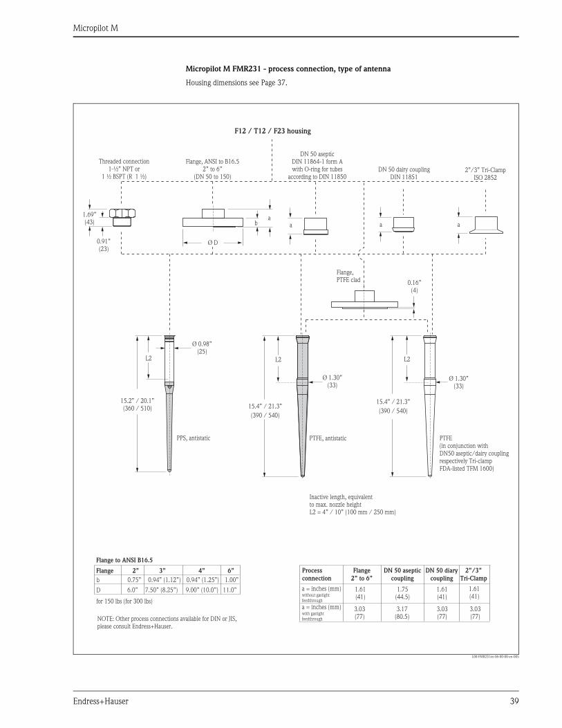
Micropilot M FMR231 - process connection, type of antenna
Housing dimensions see Page 37.
L00-FMR231xx-06-00-00-en-005
a aa
Ø 0.98”(25)
Ø D
15.2” / 20.1”(360 / 510)
L2L2L2
15.4” / 21.3”
(390 / 540)15.4” / 21.3”
(390 / 540)
Ø 1.30”(33)
Ø 1.30”(33)
1.69”(43) b
0.91”(23)
a
1.61(41)
1.61(41)
1.61(41)
3.03(77)
3.03(77)
3.03(77)
1.75(44.5)
3.17(80.5)
b
3”2”
0.94” (1.12”)0.75”
7.50” (8.25”)6.0”D 9.00” (10.0”)
0.94” (1.25”)
4”
11.0”
1.00”
6”
0.16”(4)
Threaded connection
1 ½ (R1-½” NPT or
BSPT 1 ½)
Flange, ANSI to B16.52” to 6”
(DN 50 to 150)
PPS, antistatic PTFE, antistatic
Flange,PTFE clad
DN 50 dairy couplingDIN 11851
2”/3” Tri-ClampISO 2852
a = inches (mm)without gastightfeedthrough
a = inches (mm)with gastightfeedthrough
Flange
2” to 6”
DN 50 aseptic
coupling
DN 50 diary
coupling
2”/3”
Tri-Clamp
Process
connection
Inactive length, equivalentto max. nozzle heightL2 = 4” / 10” (100 mm / 250 mm)
PTFE(in conjunction with
)
DN50 aseptic/dairy couplingrespectively Tri-clampFDA-listed TFM 1600
for 150 lbs (for 300 lbs)
NOTE: Other process connections available for DIN or JIS,please consult Endress+Hauser.
Flange
Flange to ANSI B16.5
DN 50 asepticDIN 11864-1 form Awith O-ring for tubes
according to DIN 11850
F12 / T12 / F23 housing
Micropilot M
40 Endress+Hauser
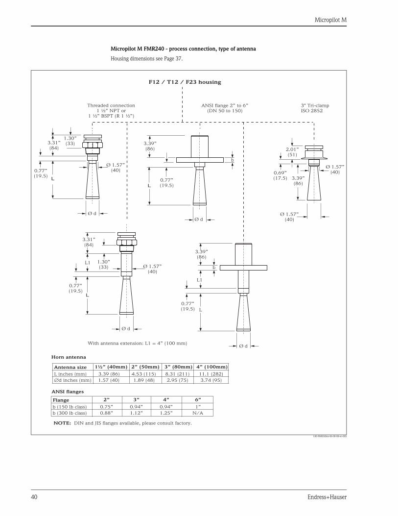
Micropilot M FMR240 - process connection, type of antenna
Housing dimensions see Page 37.
L00-FMR240xx-06-00-00-en-005
L
L 3.39”(86)
3.39”(86)
L
L
L1
b
b
L1
0.69”(17.5)
0.77”(19.5)
0.77”(19.5)
0.77”(19.5)
0.77”(19.5)
Ø d
Ø d Ø 1.57”(40)
Ø 1.57”(40)
Ø 1.57”(40)
Ø 1.57”(40)
Ø d
Ø d
3.39”(86)
3.31”(84)
3.31”(84)
2.01”(51)
1.30”(33)
1.30”(33)
2” (50mm)
3”
1½” (40mm)
2”
4.53 (115)
0.94”
3.39 (86)
0.75”
1.89 (48)
1.12”
1.57 (40)
0.88”
2.95 (75)
1.25”
8.31 (211)
0.94”
3” (80mm)
4”
3.74 (95)
N/A
11.1 (282)
1”
4” (100mm)
6”
L inches (mm)
b (150 lb class)
Æd inches (mm)
b (300 lb class)
3" Tri-clampISO 2852
With antenna extension: L1 = 4” (100 mm)
Threaded connection
BSPT (R 1 ½”)1 ½” NPT or
1 ½”
ANSI flange 2” to 6”(DN 50 to 150)
Antenna size
Flange
Horn antenna
ANSI flanges
F12 / T12 / F23 housing
NOTE: DIN and JIS flanges available, please consult factory.
Micropilot M
Endress+Hauser 41
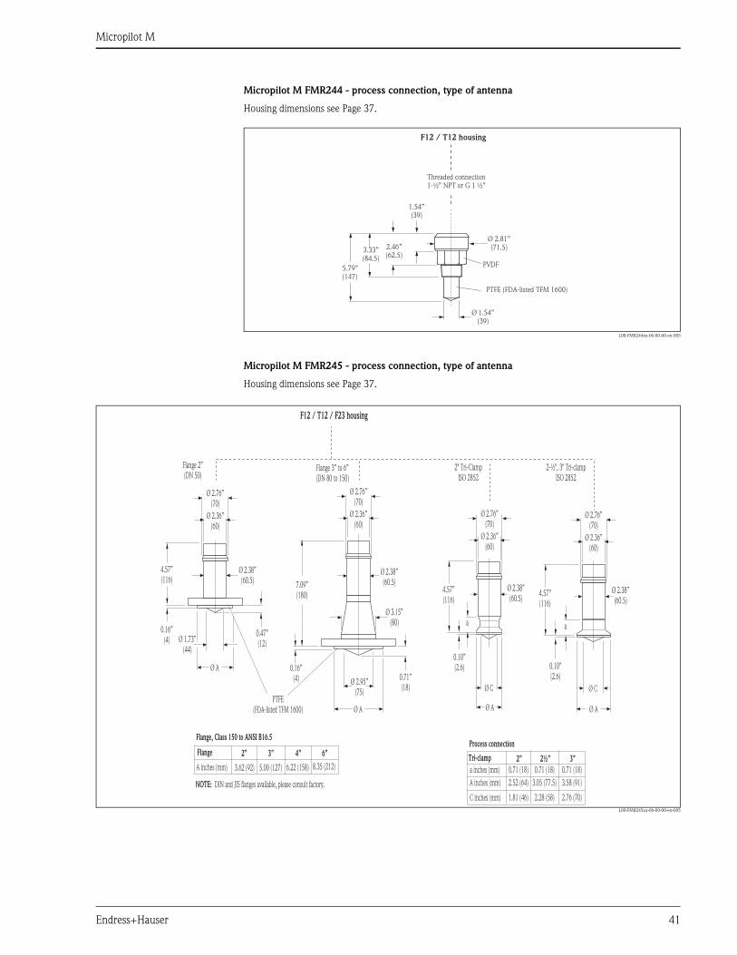
Micropilot M FMR244 - process connection, type of antenna
Housing dimensions see Page 37.
L00-FMR244xx-06-00-00-en-005
Micropilot M FMR245 - process connection, type of antenna
Housing dimensions see Page 37.
L00-FMR245xx-06-00-00-en-005
5.79”(147)
Ø 1.54”(39)
Ø 2.81”(71.5)3.33”
(84.5)
2.46”(62.5)
1.54”(39)
PVDF
Threaded connectionG 1 ½”1-½” NPT or
PTFE (FDA-listed TFM 1600)
F12 / T12 housing
0.47”(12)
0.71”(18)
aa0.16”
(4)
0.16”(4)
0.10”(2.6)
0.10”(2.6)Ø A
Ø A Ø AØ A
Ø 1.73”(44)
Ø 2.95”(75) Ø CØ C
4.57”(116)
7.09”(180)
a inches (mm)
3”2½”
2”2”
3.05 (77.5)
5.00 (127)
2.28 (58)
2.52 (64)
3.62 (92)
1.81 (46)
A inches (mm)
A inches (mm)
C inches (mm)
3.58 (91)
6.22 (158)
2.76 (70)
0.71 (18)0.71 (18)0.71 (18)
4”3”
8.35 (212)
6”
Ø 3.15”(80)
2-½", 3" Tri-clampISO 2852
Tri-clamp
Ø 2.76”(70)
Ø 2.76”(70)
Ø 2.76”(70)
Ø 2.76”(70)
Ø 2.36”(60)
Ø 2.36”(60)
Ø 2.36”(60)
Ø 2.36”(60)
4.57”(116)
4.57”(116)
Ø 2.38”(60.5)
Ø 2.38”(60.5)
Ø 2.38”(60.5)
Ø 2.38”(60.5)
Flange 2”(DN 50)
Flange 3” to 6”(DN 80 to 150)
Flange
Flange, Class 150 to ANSI B16.5Process connection
PTFE(FDA-listed TFM 1600)
F12 / T12 / F23 housing
NOTE: DIN and JIS flanges available, please consult factory.
2" Tri-ClampISO 2852
Micropilot M
42 Endress+Hauser
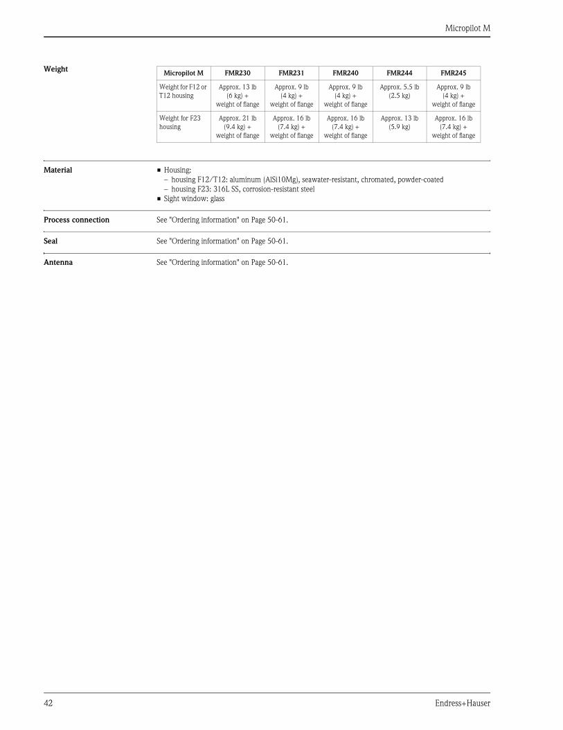
Weight
Material • Housing:
– housing F12/T12: aluminum (AlSi10Mg), seawater-resistant, chromated, powder-coated
– housing F23: 316L SS, corrosion-resistant steel
• Sight window: glass
Process connection See "Ordering information" on Page 50-61.
Seal See "Ordering information" on Page 50-61.
Antenna See "Ordering information" on Page 50-61.
Micropilot M FMR230 FMR231 FMR240 FMR244 FMR245
Weight for F12 or
T12 housing
Approx. 13 lb
(6 kg) +
weight of flange
Approx. 9 lb
(4 kg) +
weight of flange
Approx. 9 lb
(4 kg) +
weight of flange
Approx. 5.5 lb
(2.5 kg)
Approx. 9 lb
(4 kg) +
weight of flange
Weight for F23
housing
Approx. 21 lb
(9.4 kg) +
weight of flange
Approx. 16 lb
(7.4 kg) +
weight of flange
Approx. 16 lb
(7.4 kg) +
weight of flange
Approx. 13 lb
(5.9 kg)
Approx. 16 lb
(7.4 kg) +
weight of flange
Micropilot M
Endress+Hauser 43
Human interface
Operation concept The display of the process value and the configuration of the Micropilot occur locally by means of a large 4-line
alphanumeric display with plain text information. The guided menu system with integrated help texts ensures
a quick and safe commissioning.
To access the display the cover of the electronic compartment may be removed even in hazardous area (IS and
XP).
Remote commissioning, including documentation of the measuring point and in-depth analysis functions, is
supported via the ToF Tool, the graphical operating software for E+H time-of-flight systems.
Display elements Liquid crystal display (LCD):
Four lines with 20 characters each. Display contrast adjustable through key combination.
L00-FMxxxxxx-07-00-00-en-001
The VU331 LCD display can be removed to ease operation by simply pressing the snap-fit (see graphic above).
It is connected to the device by means of a 500 mm (20") cable.
The following table describes the symbols that appear on the liquid crystal display:
ENDRESS + HAUSER
E+–
ENDRESS+HAUSER
MICROPILOT II
ENDRESS+HAUSER
MICROPILOT II
IP 65IP 65
Order Code:Ser.-No.:
Order Code:Ser.-No.:
MessbereichMeasuring range
MessbereichMeasuring rangeU 16...36 V DC
4...20 mA
U 16...36 V DC4...20 mA
max. 20 m
max. 20 m
Ma
de
in
Ge
rma
ny
M
au
lbu
rgM
ad
e in
Ge
rma
ny
M
au
lbu
rg
T>70°C :
A
t >85°C
T>70°C :
A
t >85°C
LCD
Symbols
3 keys
Snap fit
Sybmol Meaning
ALARM_SYMBOL
This alarm symbol appears when the instrument is in an alarm state. If the symbol flashes, this indicates a
warning.
LOCK_SYMBOL
This lock symbol appears when the instrument is locked,i.e. if no input is possible.
COM_SYMBOL
This communication symbol appears when a data transmission via e.g. HART, PROFIBUS PA or
FOUNDATION Fieldbus is in progress.
SIMULATION_SWITCH_ENABLE
This communication symbol appears when simulation in FOUNDATION Fieldbus is enabled via the DIP
switch.
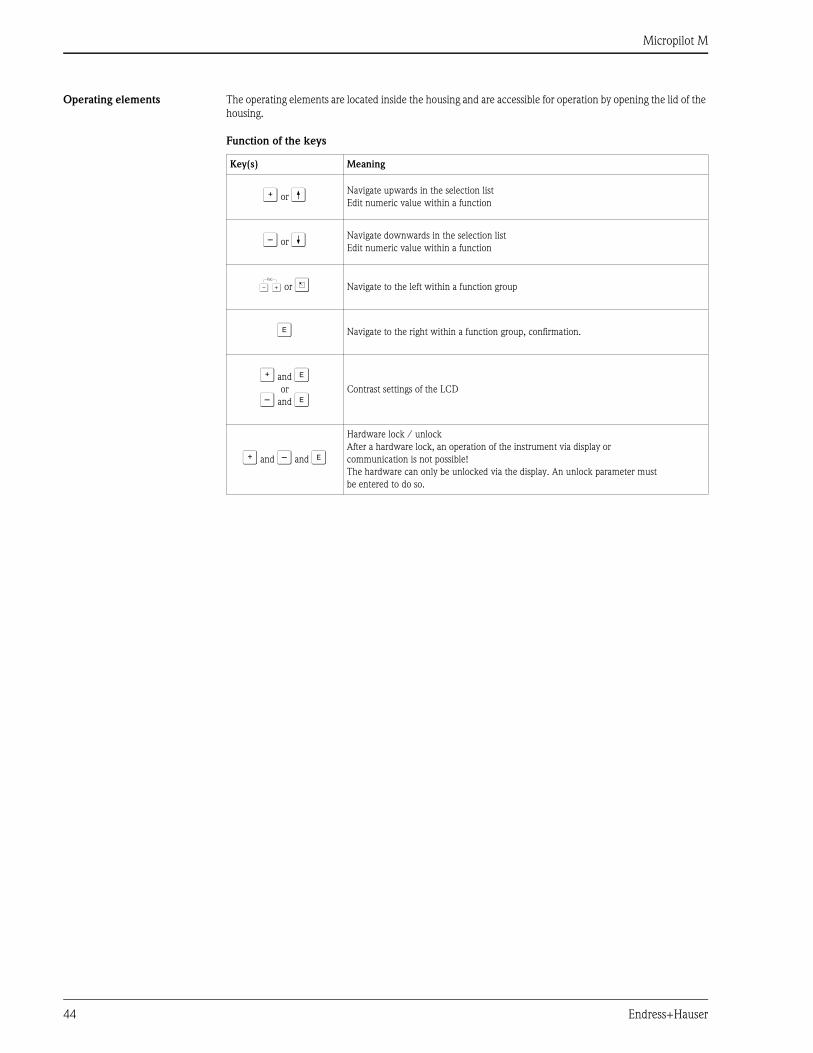
Micropilot M
44 Endress+Hauser
Operating elements The operating elements are located inside the housing and are accessible for operation by opening the lid of the
housing.
Function of the keys
Key(s) Meaning
O or V Navigate upwards in the selection list
Edit numeric value within a function
S or W Navigate downwards in the selection list
Edit numeric value within a function
X or Z Navigate to the left within a function group
F Navigate to the right within a function group, confirmation.
O and For
S and FContrast settings of the LCD
O and S and F
Hardware lock / unlock
After a hardware lock, an operation of the instrument via display or
communication is not possible!
The hardware can only be unlocked via the display. An unlock parameter must
be entered to do so.
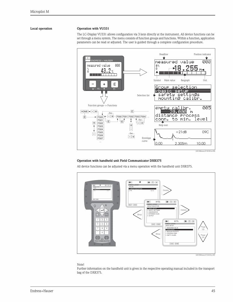
Micropilot M
Endress+Hauser 45
Local operation Operation with VU331
The LC-Display VU331 allows configuration via 3 keys directly at the instrument. All device functions can be
set through a menu system. The menu consists of function groups and functions. Within a function, application
parameters can be read or adjusted. The user is guided through a complete configuration procedure.
L00-FMRxxxxx-07-00-00-en-002
Operation with handheld unit Field Communicator DXR375
All device functions can be adjusted via a menu operation with the handheld unit DXR375.
L00-FMR2xxxx-07-00-00-yy-007
Note!
Further information on the handheld unit is given in the respective operating manual included in the transport
bag of the DXR375.
+21dB 09C
10.002.305m0.00
ENDRESS + HAUSER
E+–Bargraph
Headline Position indicator
Main value UnitSymbol
Selection list
Function groups -> Functions
Help text
Envelopecurve
HOME
FG00 F000 F001 F002 F003 F004 ...
FG01FG02FG03FG04FG05FG06FG07
...
E
E E
E
++
+
+
+
+
-
-
-
-
-
-
Esc
Esc
Esc
1# % &
Copy
G H I
P Q R S
, ( ) ‘
A B C
Paste
PageOn
PageUp
DeleteBksp
Insert
J K L
T U V
_ < >
D E F
Hot Key
+ Hot Key
M N O
W X Y Z
+ * /
4
7
.
2
5
8
0
375FIELD COMMUNICATOR
3
6
9
-
96
FMR231: LIC0001ONLINE
1 GROUP SELECT2 PV 8.7 m
HELP SAVE
dsdmdmdf das.asdas faasas la.
PageOn
PageUp
Bksp
Delete
Delete
FMR231: LIC0001ONLINE
1 GROUP SELECTION2 PV 8.7 m
HELP SAVE
dsdmdmdf das.asdas faasas la.
FMR231: LIC0001GROUP SELECTION
HOMESAVE
dsdmdmdf das.asdas faasas la.H
FMR231: LIC0001
HOMESAVE
dsdmdmdf das.asdas faasas la.H
Bksp
1 BASIC SETUP2 SAFETY SETTINGS
BASIC SETUP
1 MEASURED VALUE
4 PROCESS COND.
5 EMPTY CALIBR.
3 MEDIUM PROPERTY
4 EXTENDED CALIB.
5 OUTPUT
3 LINEARISATION
2 TANK SHAPE
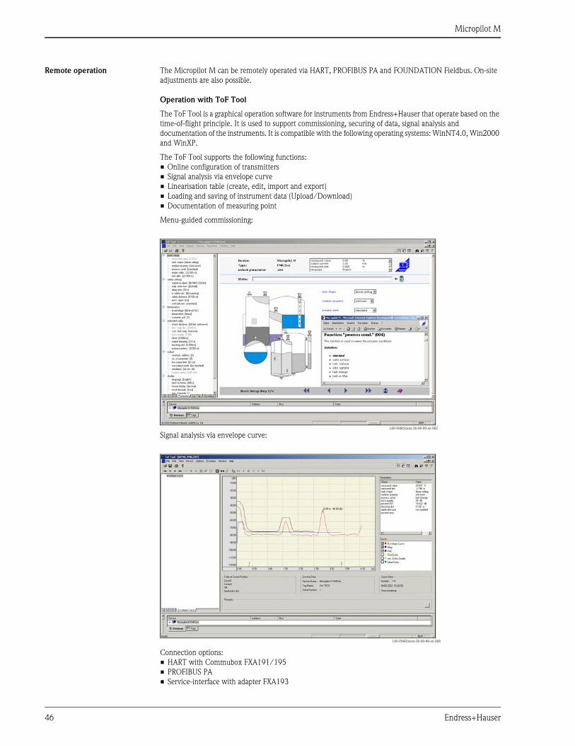
Micropilot M
46 Endress+Hauser
Remote operation The Micropilot M can be remotely operated via HART, PROFIBUS PA and FOUNDATION Fieldbus. On-site
adjustments are also possible.
Operation with ToF Tool
The ToF Tool is a graphical operation software for instruments from Endress+Hauser that operate based on the
time-of-flight principle. It is used to support commissioning, securing of data, signal analysis and
documentation of the instruments. It is compatible with the following operating systems: WinNT4.0, Win2000
and WinXP.
The ToF Tool supports the following functions:
• Online configuration of transmitters
• Signal analysis via envelope curve
• Linearisation table (create, edit, import and export)
• Loading and saving of instrument data (Upload/Download)
• Documentation of measuring point
Menu-guided commissioning:
Signal analysis via envelope curve:
Connection options:
• HART with Commubox FXA191/195
• PROFIBUS PA
• Service-interface with adapter FXA193
L00-FMR2xxxx-20-00-00-en-002
L00-FMR2xxxx-20-00-00-en-008
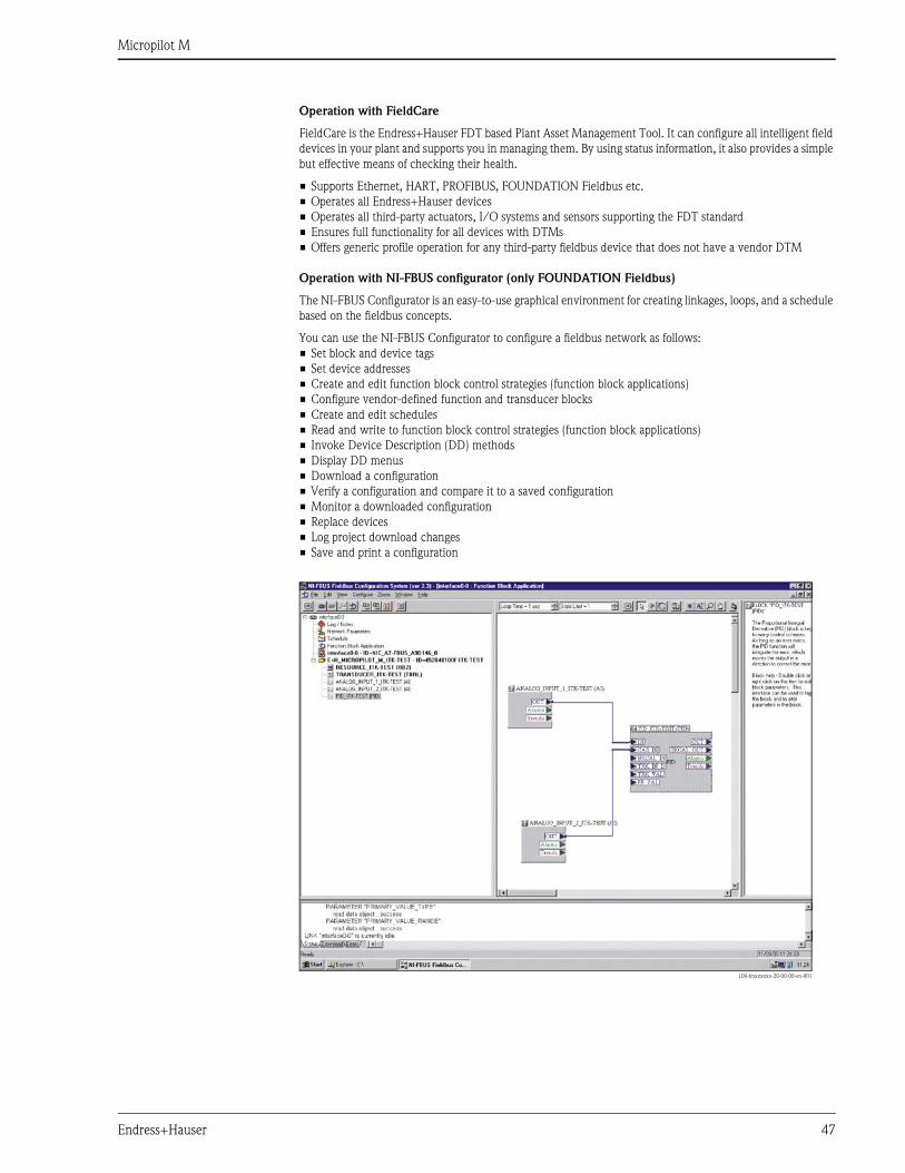
Micropilot M
Endress+Hauser 47
Operation with FieldCare
FieldCare is the Endress+Hauser FDT based Plant Asset Management Tool. It can configure all intelligent field
devices in your plant and supports you in managing them. By using status information, it also provides a simple
but effective means of checking their health.
• Supports Ethernet, HART, PROFIBUS, FOUNDATION Fieldbus etc.
• Operates all Endress+Hauser devices
• Operates all third-party actuators, I/O systems and sensors supporting the FDT standard
• Ensures full functionality for all devices with DTMs
• Offers generic profile operation for any third-party fieldbus device that does not have a vendor DTM
Operation with NI-FBUS configurator (only FOUNDATION Fieldbus)
The NI-FBUS Configurator is an easy-to-use graphical environment for creating linkages, loops, and a schedule
based on the fieldbus concepts.
You can use the NI-FBUS Configurator to configure a fieldbus network as follows:
• Set block and device tags
• Set device addresses
• Create and edit function block control strategies (function block applications)
• Configure vendor-defined function and transducer blocks
• Create and edit schedules
• Read and write to function block control strategies (function block applications)
• Invoke Device Description (DD) methods
• Display DD menus
• Download a configuration
• Verify a configuration and compare it to a saved configuration
• Monitor a downloaded configuration
• Replace devices
• Log project download changes
• Save and print a configuration
L00-fmxxxxxx-20-00-00-en-001

Micropilot M
48 Endress+Hauser
Certificates and approvals
CE approval The measuring system meets the legal requirements of the EC-guidelines. Endress+Hauser confirms the
instrument passing the required tests by attaching the CE-mark.
Hazardous approvals See "Ordering information" on Page 50-61.
Sanitary compatibility
Note!
The leak-tight connections can be cleaned with the cleaning methods usually used in this industry without
leaving residues.
Overspill protection German WHG. See "Ordering information" on Page 50-61 (see ZE244F/00/de).
SIL 2, for 4 to 20 mA output signal (see SD150F/00/en "Functional Safety Manual").
Marine certificate GL (Germanisch Lloyd), ABS, NK
– HART, PROFIBUS PA
– not HT antenna
External standards and
guidelines
EN 60529
Protection class of housing (IP-code)
EN 61010
Safety regulations for electrical devices for measurement, control, regulation and laboratory use.
EN 61326
Emissions (equipment class B), compatibility (appendix A – industrial area)
NAMUR
Standards committee for measurement and control in the chemical industry
RF approvals R&TTE, FCC
Pressure measuring device
guideline
The instruments of the Micropilot M product family are not subject to the scope of the EC Directive
97/23/EC (Pressure Measuring Device Guideline).
FMR231 with PTFE-antenna made of FDA-
listed TFM 1600.
FMR245 with flange cladding made of FDA-
listed TFM 1600
– 3-A/EHEDG approval with Tri-clamp
process connection.
– TFM 1600 meets USP Class VI
conformity
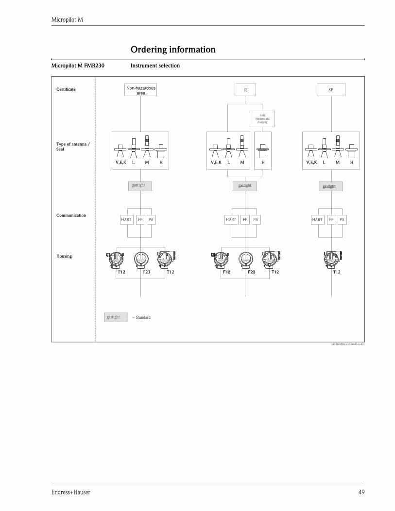
Micropilot M
Endress+Hauser 49
Ordering information
Micropilot M FMR230 Instrument selection
L00-FMR230xx-16-00-00-en-001
T12
V,E,K L M H V,E,K L M HV,E,K L M
T12 T12F12 F12
H
HART HART HARTPA PA PAFF FF FF
XPIS
F23 F23
Certificate
Type of antenna /
Seal
Communication
Housing
gastightgastight gastight
gastight = Standard
Non-hazardousarea
noteelectrostatic
charging!
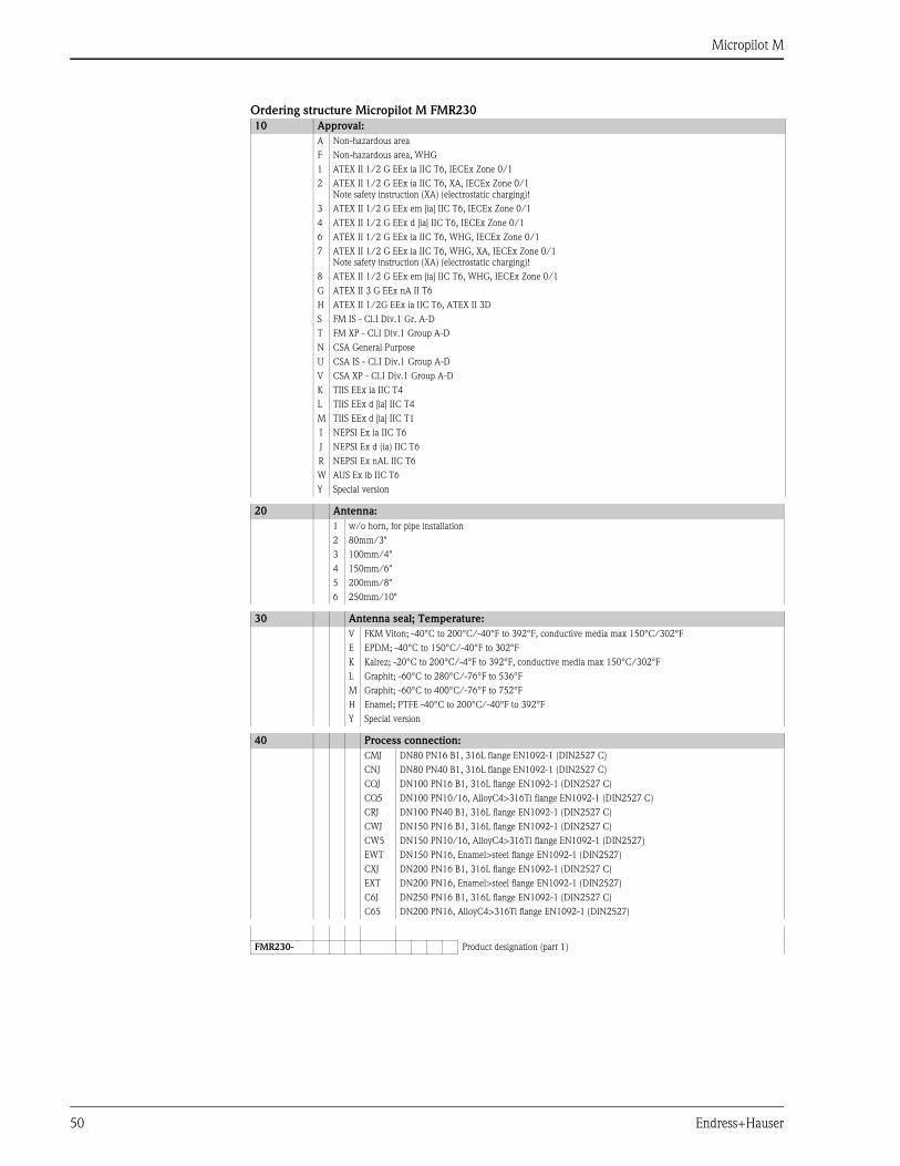
Micropilot M
50 Endress+Hauser
Ordering structure Micropilot M FMR230
10 Approval:
A Non-hazardous area
F Non-hazardous area, WHG
1 ATEX II 1/2 G EEx ia IIC T6, IECEx Zone 0/1
2 ATEX II 1/2 G EEx ia IIC T6, XA, IECEx Zone 0/1
Note safety instruction (XA) (electrostatic charging)!
3 ATEX II 1/2 G EEx em [ia] IIC T6, IECEx Zone 0/1
4 ATEX II 1/2 G EEx d [ia] IIC T6, IECEx Zone 0/1
6 ATEX II 1/2 G EEx ia IIC T6, WHG, IECEx Zone 0/1
7 ATEX II 1/2 G EEx ia IIC T6, WHG, XA, IECEx Zone 0/1
Note safety instruction (XA) (electrostatic charging)!
8 ATEX II 1/2 G EEx em [ia] IIC T6, WHG, IECEx Zone 0/1
G ATEX II 3 G EEx nA II T6
H ATEX II 1/2G EEx ia IIC T6, ATEX II 3D
S FM IS - Cl.I Div.1 Gr. A-D
T FM XP - Cl.I Div.1 Group A-D
N CSA General Purpose
U CSA IS - Cl.I Div.1 Group A-D
V CSA XP - Cl.I Div.1 Group A-D
K TIIS EEx ia IIC T4
L TIIS EEx d [ia] IIC T4
M TIIS EEx d [ia] IIC T1
I NEPSI Ex ia IIC T6
J NEPSI Ex d (ia) IIC T6
R NEPSI Ex nAL IIC T6
W AUS Ex ib IIC T6
Y Special version
20 Antenna:
1 w/o horn, for pipe installation
2 80mm/3"
3 100mm/4"
4 150mm/6"
5 200mm/8"
6 250mm/10"
30 Antenna seal; Temperature:
V FKM Viton; -40°C to 200°C/-40°F to 392°F, conductive media max 150°C/302°F
E EPDM; -40°C to 150°C/-40°F to 302°F
K Kalrez; -20°C to 200°C/-4°F to 392°F, conductive media max 150°C/302°F
L Graphit; -60°C to 280°C/-76°F to 536°F
M Graphit; -60°C to 400°C/-76°F to 752°F
H Enamel; PTFE -40°C to 200°C/-40°F to 392°F
Y Special version
40 Process connection:
CMJ DN80 PN16 B1, 316L flange EN1092-1 (DIN2527 C)
CNJ DN80 PN40 B1, 316L flange EN1092-1 (DIN2527 C)
CQJ DN100 PN16 B1, 316L flange EN1092-1 (DIN2527 C)
CQ5 DN100 PN10/16, AlloyC4>316Ti flange EN1092-1 (DIN2527 C)
CRJ DN100 PN40 B1, 316L flange EN1092-1 (DIN2527 C)
CWJ DN150 PN16 B1, 316L flange EN1092-1 (DIN2527 C)
CW5 DN150 PN10/16, AlloyC4>316Ti flange EN1092-1 (DIN2527)
EWT DN150 PN16, Enamel>steel flange EN1092-1 (DIN2527)
CXJ DN200 PN16 B1, 316L flange EN1092-1 (DIN2527 C)
EXT DN200 PN16, Enamel>steel flange EN1092-1 (DIN2527)
C6J DN250 PN16 B1, 316L flange EN1092-1 (DIN2527 C)
C65 DN200 PN16, AlloyC4>316Ti flange EN1092-1 (DIN2527)
FMR230- Product designation (part 1)
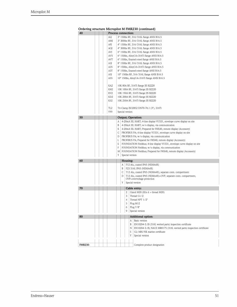
Micropilot M
Endress+Hauser 51
Ordering structure Micropilot M FMR230 (continued)
40 Process connection:
ALJ 3" 150lbs RF, 316/316L flange ANSI B16.5
AMJ 3" 300lbs RF, 316/316L flange ANSI B16.5
APJ 4" 150lbs RF, 316/316L flange ANSI B16.5
AQJ 4" 300lbs RF, 316/316L flange ANSI B16.5
AVJ 6" 150lbs RF, 316/316L flange ANSI B16.5
AV5 6" 150lbs, AlloyC4>316Ti flange ANSI B16.5
AVT 6" 150lbs, Enamel>steel flange ANSI B16.5
A3J 8" 150lbs RF, 316/316L flange ANSI B16.5
A35 8" 150lbs, AlloyC4>316Ti flange ANSI B16.5
A3T 8" 150lbs, Enamel>steel flange ANSI B16.5
A5J 10" 150lbs RF, 316/316L flange ANSI B16.5
A55 10" 150lbs, AlloyC4>316Ti flange ANSI B16.5
KA2 10K 80A RF, 316Ti flange JIS B2220
KH2 10K 100A RF, 316Ti flange JIS B2220
KV2 10K 150A RF, 316Ti flange JIS B2220
KD2 10K 200A RF, 316Ti flange JIS B2220
K52 10K 250A RF, 316Ti flange JIS B2220
TL2 Tri-Clamp ISO2852 DN70-76.1 (3"), 316Ti
YY9 Special version
50 Output; Operation:
A 4-20mA SIL HART; 4-line display VU331, envelope curve display on site
B 4-20mA SIL HART; w/o display, via communication
K 4-20mA SIL HART; Prepared for FHX40, remote display (Accessory)
C PROFIBUS PA; 4-line display VU331, envelope curve display on site
D PROFIBUS PA; w/o display, via communication
L PROFIBUS PA; Prepared for FHX40, remote display (Accessory)
E FOUNDATION Fieldbus; 4-line display VU331, envelope curve display on site
F FOUNDATION Fieldbus; w/o display, via communication
M FOUNDATION Fieldbus; Prepared for FHX40, remote display (Accessory)
Y Special version
60 Housing:
A F12 Alu, coated IP65 (NEMA4X)
B F23 316L IP65 (NEMA4X)
C T12 Alu, coated IP65 (NEMA4X), separate conn. compartment
D T12 Alu, coated IP65 (NEMA4X)+OVP, separate conn. compartment,
OVP=overvoltage protection
Y Special version
70 Cable entry:
2 Gland M20 (EEx d > thread M20)
3 Thread G1/2
4 Thread NPT 1/2"
5 Plug M12
6 Plug 7/8"
9 Special version
80 Additional option:
A Basic version
B EN10204-3.1B (316L wetted parts) inspection certificate
N EN10204-3.1B, NACE MR0175 (316L wetted parts) inspection certificate
S GL/ABS/NK marine certificate
Y Special version
FMR230- Complete product designation
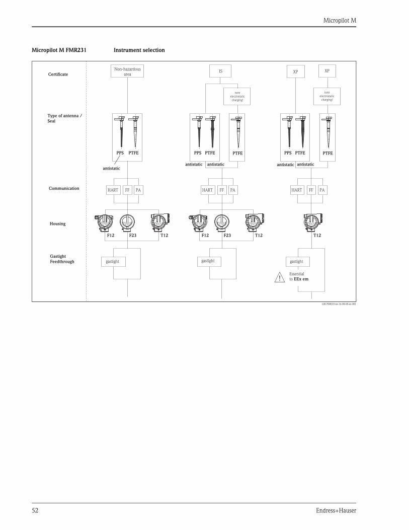
Micropilot M
52 Endress+Hauser
Micropilot M FMR231 Instrument selection
L00-FMR231xx-16-00-00-en-001
PPS PTFE PTFE PTFEPPS PTFE PPS PTFE
XP XPIS
antistatic
T12 T12 T12F23 F23F12 F12
HART HART HARTPA PA PAFF FF FF
Non-hazardousareaCertificate
Type of antenna /
Seal
Communication
Housing
Gastight
Feedthrough gastight gastight gastight
Essentialto EEx em
noteelectrostatic
charging!
noteelectrostatic
charging!
antistatic antistaticantistatic antistatic
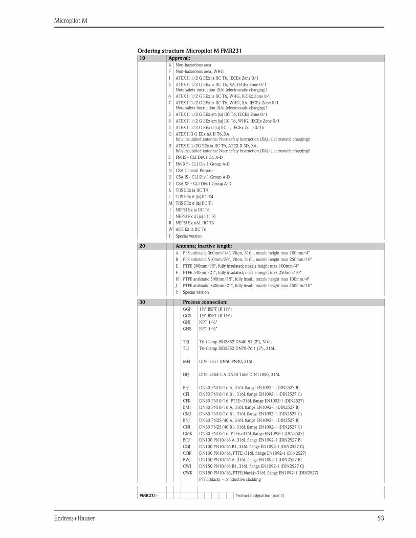
Micropilot M
Endress+Hauser 53
Ordering structure Micropilot M FMR231
10 Approval:
A Non-hazardous area
F Non-hazardous area, WHG
1 ATEX II 1/2 G EEx ia IIC T6, IECEx Zone 0/1
2 ATEX II 1/2 G EEx ia IIC T6, XA, IECEx Zone 0/1
Note safety instruction (XA) (electrostatic charging)!
6 ATEX II 1/2 G EEx ia IIC T6, WHG, IECEx Zone 0/1
7 ATEX II 1/2 G EEx ia IIC T6, WHG, XA, IECEx Zone 0/1
Note safety instruction (XA) (electrostatic charging)!
3 ATEX II 1/2 G EEx em [ia] IIC T6, IECEx Zone 0/1
8 ATEX II 1/2 G EEx em [ia] IIC T6, WHG, IECEx Zone 0/1
4 ATEX II 1/2 G EEx d [ia] IIC T, IECEx Zone 0/16
G ATEX II 3 G EEx nA II T6, XA,
fully insutalted antenna: Note safety instruction (XA) (electrostatic charging)!
H ATEX II 1/2G EEx ia IIC T6, ATEX II 3D, XA,
fully insutalted antenna: Note safety instruction (XA) (electrostatic charging)!
S FM IS - Cl.I Div.1 Gr. A-D
T FM XP - Cl.I Div.1 Group A-D
N CSA General Purpose
U CSA IS - Cl.I Div.1 Group A-D
V CSA XP - Cl.I Div.1 Group A-D
K TIIS EEx ia IIC T4
L TIIS EEx d [ia] IIC T4
M TIIS EEx d [ia] IIC T1
I NEPSI Ex ia IIC T6
J NEPSI Ex d (ia) IIC T6
R NEPSI Ex nAL IIC T6
W AUS Ex ib IIC T6
Y Special version
20 Antenna; Inactive length:
A PPS antistatic 360mm/14", Viton, 316L; nozzle height max 100mm/4"
B PPS antistatic 510mm/20", Viton, 316L; nozzle height max 250mm/10"
E PTFE 390mm/15", fully insulated; nozzle height max 100mm/4"
F PTFE 540mm/21", fully insulated; nozzle height max 250mm/10"
H PTFE antistatic 390mm/15", fully insul.; nozzle height max 100mm/4"
J PTFE antistatic 540mm/21", fully insul.; nozzle height max 250mm/10"
Y Special version
30 Process connection:
GGJ 1½" BSPT (R 1½")
GGS 1½" BSPT (R 1½")
GNJ NPT 1-½"
GNS NPT 1-½"
TEJ Tri-Clamp ISO2852 DN40-51 (2"), 316L
TLJ Tri-Clamp ISO2852 DN70-76.1 (3"), 316L
MFJ DIN11851 DN50 PN40, 316L
HFJ DIN11864-1 A DN50 Tube DIN11850, 316L
BFJ DN50 PN10/16 A, 316L flange EN1092-1 (DIN2527 B)
CFJ DN50 PN10/16 B1, 316L flange EN1092-1 (DIN2527 C)
CFK DN50 PN10/16, PTFE>316L flange EN1092-1 (DIN2527)
BMJ DN80 PN10/16 A, 316L flange EN1092-1 (DIN2527 B)
CMJ DN80 PN10/16 B1, 316L flange EN1092-1 (DIN2527 C)
BNJ DN80 PN25/40 A, 316L flange EN1092-1 (DIN2527 B)
CNJ DN80 PN25/40 B1, 316L flange EN1092-1 (DIN2527 C)
CMK DN80 PN10/16, PTFE>316L flange EN1092-1 (DIN2527)
BQJ DN100 PN10/16 A, 316L flange EN1092-1 (DIN2527 B)
CQJ DN100 PN10/16 B1, 316L flange EN1092-1 (DIN2527 C)
CQK DN100 PN10/16, PTFE>316L flange EN1092-1 (DIN2527)
BWJ DN150 PN10/16 A, 316L flange EN1092-1 (DIN2527 B)
CWJ DN150 PN10/16 B1, 316L flange EN1092-1 (DIN2527 C)
CWK DN150 PN10/16, PTFE(black)>316L flange EN1092-1 (DIN2527)
PTFE(black) = conductive cladding
FMR231- Product designation (part 1)
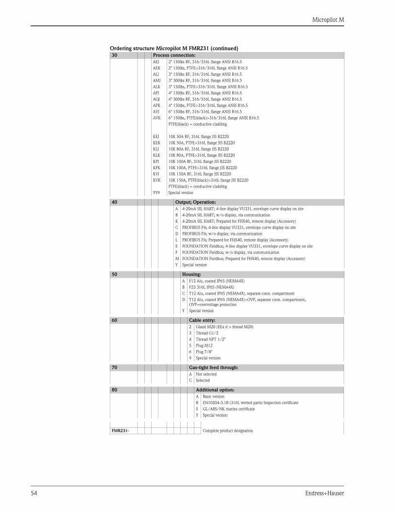
Micropilot M
54 Endress+Hauser
Ordering structure Micropilot M FMR231 (continued)
30 Process connection:
AEJ 2" 150lbs RF, 316/316L flange ANSI B16.5
AEK 2" 150lbs, PTFE>316/316L flange ANSI B16.5
ALJ 3" 150lbs RF, 316/316L flange ANSI B16.5
AMJ 3" 300lbs RF, 316/316L flange ANSI B16.5
ALK 3" 150lbs, PTFE>316/316L flange ANSI B16.5
APJ 4" 150lbs RF, 316/316L flange ANSI B16.5
AQJ 4" 300lbs RF, 316/316L flange ANSI B16.5
APK 4" 150lbs, PTFE>316/316L flange ANSI B16.5
AVJ 6" 150lbs RF, 316/316L flange ANSI B16.5
AVK 6" 150lbs, PTFE(black)>316/316L flange ANSI B16.5
PTFE(black) = conductive cladding
KEJ 10K 50A RF, 316L flange JIS B2220
KEK 10K 50A, PTFE>316L flange JIS B2220
KLJ 10K 80A RF, 316L flange JIS B2220
KLK 10K 80A, PTFE>316L flange JIS B2220
KPJ 10K 100A RF, 316L flange JIS B2220
KPK 10K 100A, PTFE>316L flange JIS B2220
KVJ 10K 150A RF, 316L flange JIS B2220
KVK 10K 150A, PTFE(black)>316L flange JIS B2220
PTFE(black) = conductive cladding
YY9 Special version
40 Output; Operation:
A 4-20mA SIL HART; 4-line display VU331, envelope curve display on site
B 4-20mA SIL HART; w/o display, via communication
K 4-20mA SIL HART; Prepared for FHX40, remote display (Accessory)
C PROFIBUS PA; 4-line display VU331, envelope curve display on site
D PROFIBUS PA; w/o display, via communication
L PROFIBUS PA; Prepared for FHX40, remote display (Accessory)
E FOUNDATION Fieldbus; 4-line display VU331, envelope curve display on site
F FOUNDATION Fieldbus; w/o display, via communication
M FOUNDATION Fieldbus; Prepared for FHX40, remote display (Accessory)
Y Special version
50 Housing:
A F12 Alu, coated IP65 (NEMA4X)
B F23 316L IP65 (NEMA4X)
C T12 Alu, coated IP65 (NEMA4X), separate conn. compartment
D T12 Alu, coated IP65 (NEMA4X)+OVP, separate conn. compartment,
OVP=overvoltage protection
Y Special version
60 Cable entry:
2 Gland M20 (EEx d > thread M20)
3 Thread G1/2
4 Thread NPT 1/2"
5 Plug M12
6 Plug 7/8"
9 Special version
70 Gas-tight feed through:
A Not selected
C Selected
80 Additional option:
A Basic version
B EN10204-3.1B (316L wetted parts) Inspection certificate
S GL/ABS/NK marine certificate
Y Special version
FMR231- Complete product designation
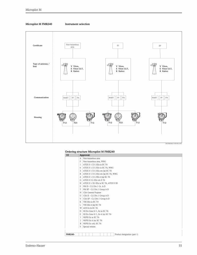
Micropilot M
Endress+Hauser 55
Micropilot M FMR240 Instrument selection
L00-FMR240xx-16-00-00-en-001
Ordering structure Micropilot M FMR240
XPIS
T12 T12 T12F23 F23F12 F12
HART HART HARTPA PA PAFF FF FF
V Viton,
E Viton GLT,
K Kalrez
V Viton,
E Viton GLT,
K Kalrez
V Viton,
E Viton GLT,
K Kalrez
Non-hazardousarea
Certificate
Type of antenna /
Seal
Communication
Housing
10 Approval:
A Non-hazardous area
F Non-hazardous area, WHG
1 ATEX II 1/2 G EEx ia IIC T6
6 ATEX II 1/2 G EEx ia IIC T6, WHG
3 ATEX II 1/2 G EEx em [ia] IIC T6
8 ATEX II 1/2 G EEx em [ia] IIC T6, WHG
4 ATEX II 1/2 G EEx d [ia] IIC T6
G ATEX II 3 G EEx nA II T6
H ATEX II 1/2G EEx ia IIC T6, ATEX II 3D
S FM IS - Cl.I Div.1 Gr. A-D
T FM XP - Cl.I Div.1 Group A-D
N CSA General Purpose
U CSA IS - Cl.I Div.1 Group A-D
V CSA XP - Cl.I Div.1 Group A-D
K TIIS EEx ia IIC T4
L TIIS EEx d [ia] IIC T4
W AUS Ex ib IIC T6
D IECEx Zone 0/1, Ex ia IIC T6
E IECEx Zone 0/1, Ex d (ia) IIC T6
I NEPSI Ex ia IIC T6
J NEPSI Ex d (ia) IIC T6
R NEPSI Ex nAL IIC T6
Y Special version
FMR240- Product designation (part 1)

Micropilot M
56 Endress+Hauser
Ordering structure Micropilot M FMR240 (continued)
20 Antenna:
2 40mm/1-1/2"
3 50mm/2"
4 80mm/3"
5 100mm/4"
30 Antenna seal; Temperature:
V FKM Viton; -20°C to 150°C/-4°F to 302°F
E FKM Viton GLT; -40°C to 150°C/-40°F to 302°F
K Kalrez; -20°C to 150°C/-4°F to 302°F
40 Antenna extension
1 without antenna extension
2 100 mm / 4" antenna extension
9 Special version
50 Process connection:
GGJ Thread DIN2999 R1-1/2, 316L
GNJ Thread ANSI NPT 1-1/2", 316L
TLJ Tri-Clamp ISO2852 DN70-76.1 (3"), 316L
CFJ DN50 PN10/16 B1, 316L flange EN1092-1 (DIN2527 C)
CGJ DN50 PN25/40 B1, 316L flange EN1092-1 (DIN2527 C)
CFM DN50 PN10/16, AlloyC22>316L flange EN1092-1 (DIN2527)
CGM DN50 PN25/40, AlloyC22>316L flange EN1092-1 (DIN2527)
CMJ DN80 PN10/16 B1, 316L flange EN1092-1 (DIN2527 C)
CNJ DN80 PN25/40 B1, 316L flange EN1092-1 (DIN2527 C)
CMM DN80 PN10/16, AlloyC22>316L flange EN1092-1 (DIN2527)
CNM DN80 PN25/40, AlloyC22>316L flange EN1092-1 (DIN2527)
CQJ DN100 PN10/16 B1, 316L flange EN1092-1 (DIN2527 C)
CRJ DN100 PN25/40 B1, 316L flange EN1092-1 (DIN2527 C)
CQM DN100 PN10/16, AlloyC22>316L flange EN1092-1 (DIN2527)
CRM DN100 PN25/40, AlloyC22>316L flange EN1092-1 (DIN2527)
CWJ DN150 PN10/16 B1, 316L flange EN1092-1 (DIN2527 C)
CWM DN150 PN10/16, AlloyC22>316L flange EN1092-1 (DIN2527)
AEJ 2" 150lbs RF, 316/316L flange ANSI B16.5
AFJ 2" 300lbs RF, 316/316L flange ANSI B16.5
AEM 2" 150lbs, AlloyC22>316/316L flange ANSI B16.5
AFM 2" 300lbs, AlloyC22>316/316L flange ANSI B16.5
ALJ 3" 150lbs RF, 316/316L flange ANSI B16.5
AMJ 3" 300lbs RF, 316/316L flange ANSI B16.5
ALM 3" 150lbs, AlloyC22>316/316L flange ANSI B16.5
AMM 3" 300lbs, AlloyC22>316/316L flange ANSI B16.5
APJ 4" 150lbs RF, 316/316L flange ANSI B16.5
AQJ 4" 300lbs RF, 316/316L flange ANSI B16.5
APM 4" 150lbs, AlloyC22>316/316L flange ANSI B16.5
AQM 4" 300lbs, AlloyC22>316/316L flange ANSI B16.5
AWJ 6" 150lbs RF, 316/316L flange ANSI B16.5
AWM 6" 150lbs, AlloyC22>316/316L flange ANSI B16.5
FMR240- Product designation (part 2)
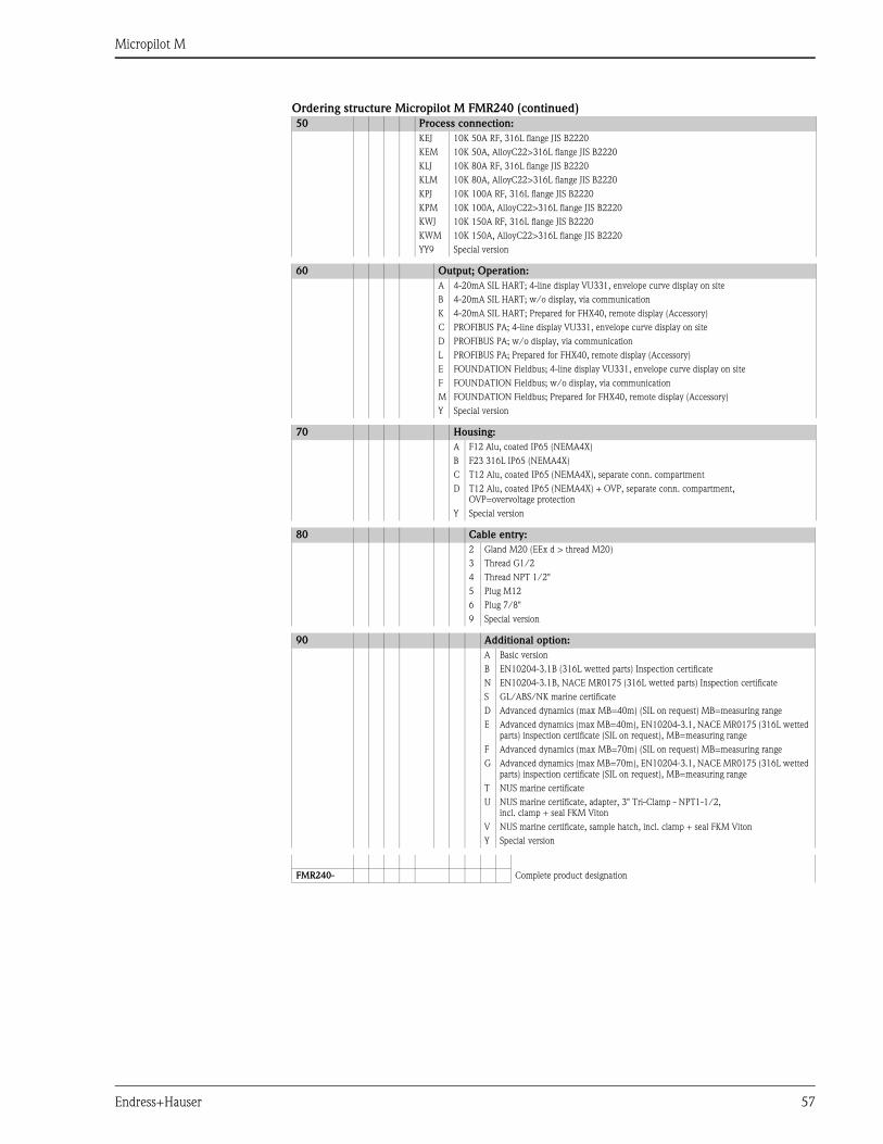
Micropilot M
Endress+Hauser 57
Ordering structure Micropilot M FMR240 (continued)
50 Process connection:
KEJ 10K 50A RF, 316L flange JIS B2220
KEM 10K 50A, AlloyC22>316L flange JIS B2220
KLJ 10K 80A RF, 316L flange JIS B2220
KLM 10K 80A, AlloyC22>316L flange JIS B2220
KPJ 10K 100A RF, 316L flange JIS B2220
KPM 10K 100A, AlloyC22>316L flange JIS B2220
KWJ 10K 150A RF, 316L flange JIS B2220
KWM 10K 150A, AlloyC22>316L flange JIS B2220
YY9 Special version
60 Output; Operation:
A 4-20mA SIL HART; 4-line display VU331, envelope curve display on site
B 4-20mA SIL HART; w/o display, via communication
K 4-20mA SIL HART; Prepared for FHX40, remote display (Accessory)
C PROFIBUS PA; 4-line display VU331, envelope curve display on site
D PROFIBUS PA; w/o display, via communication
L PROFIBUS PA; Prepared for FHX40, remote display (Accessory)
E FOUNDATION Fieldbus; 4-line display VU331, envelope curve display on site
F FOUNDATION Fieldbus; w/o display, via communication
M FOUNDATION Fieldbus; Prepared for FHX40, remote display (Accessory)
Y Special version
70 Housing:
A F12 Alu, coated IP65 (NEMA4X)
B F23 316L IP65 (NEMA4X)
C T12 Alu, coated IP65 (NEMA4X), separate conn. compartment
D T12 Alu, coated IP65 (NEMA4X) + OVP, separate conn. compartment,
OVP=overvoltage protection
Y Special version
80 Cable entry:
2 Gland M20 (EEx d > thread M20)
3 Thread G1/2
4 Thread NPT 1/2"
5 Plug M12
6 Plug 7/8"
9 Special version
90 Additional option:
A Basic version
B EN10204-3.1B (316L wetted parts) Inspection certificate
N EN10204-3.1B, NACE MR0175 (316L wetted parts) Inspection certificate
S GL/ABS/NK marine certificate
D Advanced dynamics (max MB=40m) (SIL on request) MB=measuring range
E Advanced dynamics (max MB=40m), EN10204-3.1, NACE MR0175 (316L wetted
parts) inspection certificate (SIL on request), MB=measuring range
F Advanced dynamics (max MB=70m) (SIL on request) MB=measuring range
G Advanced dynamics (max MB=70m), EN10204-3.1, NACE MR0175 (316L wetted
parts) inspection certificate (SIL on request), MB=measuring range
T NUS marine certificate
U NUS marine certificate, adapter, 3" Tri-Clamp - NPT1-1/2,
incl. clamp + seal FKM Viton
V NUS marine certificate, sample hatch, incl. clamp + seal FKM Viton
Y Special version
FMR240- Complete product designation
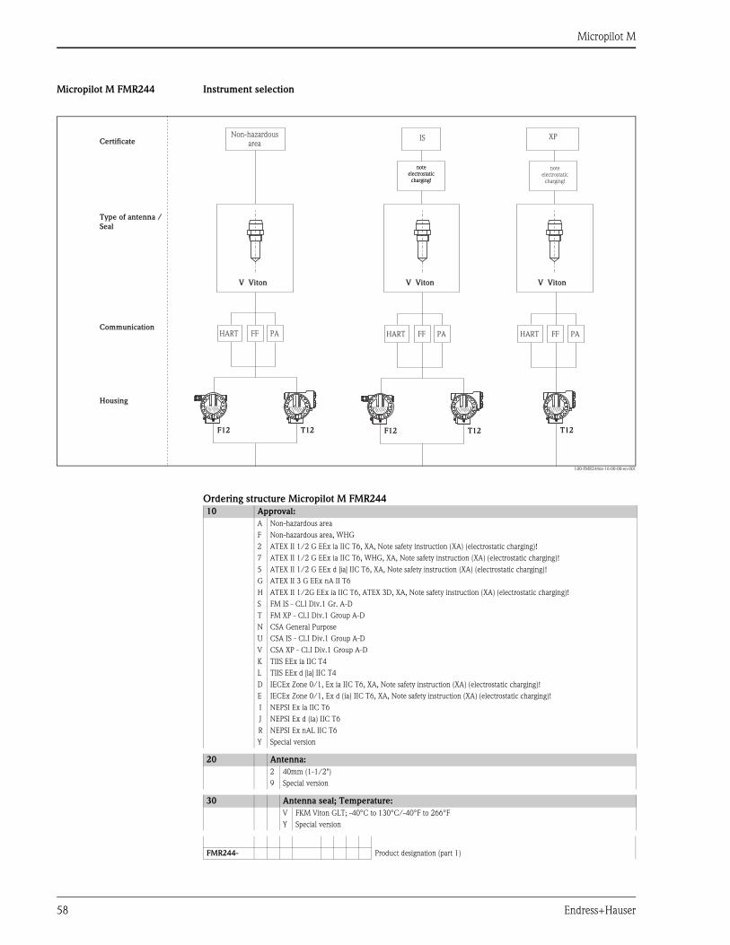
Micropilot M
58 Endress+Hauser
Micropilot M FMR244 Instrument selection
L00-FMR244xx-16-00-00-en-001
Ordering structure Micropilot M FMR244
V Viton V Viton V Viton
XPIS
T12 T12F12 F12
HART HART HARTPA PA PAFF FF FF
T12
Non-hazardousareaCertificate
Type of antenna /
Seal
Communication
Housing
noteelectrostatic
charging!
noteelectrostatic
charging!
noteelectrostatic
charging!
10 Approval:
A Non-hazardous area
F Non-hazardous area, WHG
2 ATEX II 1/2 G EEx ia IIC T6, XA, Note safety instruction (XA) (electrostatic charging)!
7 ATEX II 1/2 G EEx ia IIC T6, WHG, XA, Note safety instruction (XA) (electrostatic charging)!
5 ATEX II 1/2 G EEx d [ia] IIC T6, XA, Note safety instruction (XA) (electrostatic charging)!
G ATEX II 3 G EEx nA II T6
H ATEX II 1/2G EEx ia IIC T6, ATEX 3D, XA, Note safety instruction (XA) (electrostatic charging)!
S FM IS - Cl.I Div.1 Gr. A-D
T FM XP - Cl.I Div.1 Group A-D
N CSA General Purpose
U CSA IS - Cl.I Div.1 Group A-D
V CSA XP - Cl.I Div.1 Group A-D
K TIIS EEx ia IIC T4
L TIIS EEx d [ia] IIC T4
D IECEx Zone 0/1, Ex ia IIC T6, XA, Note safety instruction (XA) (electrostatic charging)!
E IECEx Zone 0/1, Ex d (ia) IIC T6, XA, Note safety instruction (XA) (electrostatic charging)!
I NEPSI Ex ia IIC T6
J NEPSI Ex d (ia) IIC T6
R NEPSI Ex nAL IIC T6
Y Special version
20 Antenna:
2 40mm (1-1/2")
9 Special version
30 Antenna seal; Temperature:
V FKM Viton GLT; -40°C to 130°C/-40°F to 266°F
Y Special version
FMR244- Product designation (part 1)
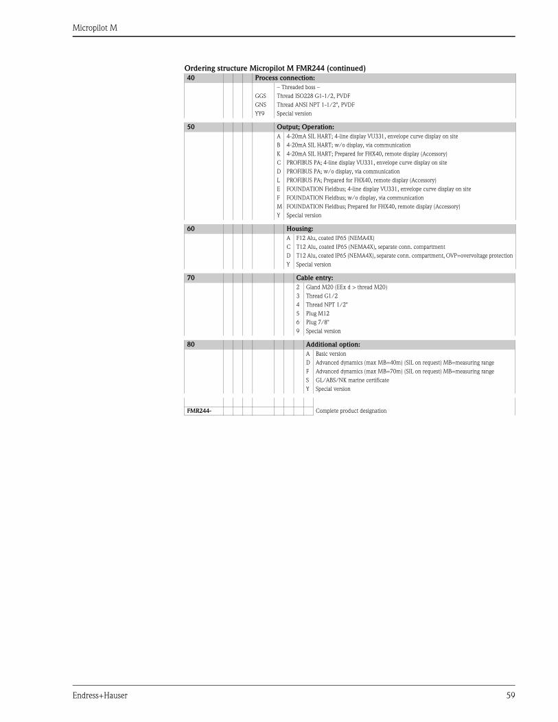
Micropilot M
Endress+Hauser 59
Ordering structure Micropilot M FMR244 (continued)
40 Process connection:
– Threaded boss –
GGS Thread ISO228 G1-1/2, PVDF
GNS Thread ANSI NPT 1-1/2", PVDF
YY9 Special version
50 Output; Operation:
A 4-20mA SIL HART; 4-line display VU331, envelope curve display on site
B 4-20mA SIL HART; w/o display, via communication
K 4-20mA SIL HART; Prepared for FHX40, remote display (Accessory)
C PROFIBUS PA; 4-line display VU331, envelope curve display on site
D PROFIBUS PA; w/o display, via communication
L PROFIBUS PA; Prepared for FHX40, remote display (Accessory)
E FOUNDATION Fieldbus; 4-line display VU331, envelope curve display on site
F FOUNDATION Fieldbus; w/o display, via communication
M FOUNDATION Fieldbus; Prepared for FHX40, remote display (Accessory)
Y Special version
60 Housing:
A F12 Alu, coated IP65 (NEMA4X)
C T12 Alu, coated IP65 (NEMA4X), separate conn. compartment
D T12 Alu, coated IP65 (NEMA4X), separate conn. compartment, OVP=overvoltage protection
Y Special version
70 Cable entry:
2 Gland M20 (EEx d > thread M20)
3 Thread G1/2
4 Thread NPT 1/2"
5 Plug M12
6 Plug 7/8"
9 Special version
80 Additional option:
A Basic version
D Advanced dynamics (max MB=40m) (SIL on request) MB=measuring range
F Advanced dynamics (max MB=70m) (SIL on request) MB=measuring range
S GL/ABS/NK marine certificate
Y Special version
FMR244- Complete product designation
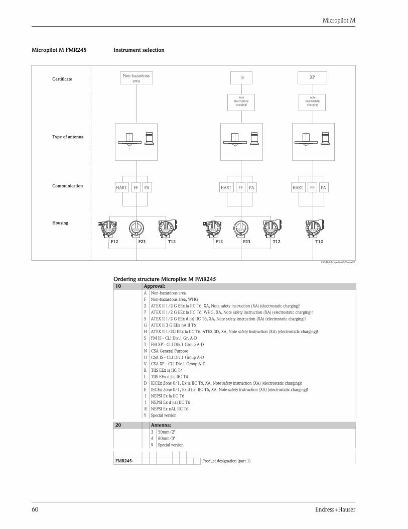
Micropilot M
60 Endress+Hauser
Micropilot M FMR245 Instrument selection
L00-FMR245xx-16-00-00-en-001
Ordering structure Micropilot M FMR245
XPIS
T12 T12 T12F23 F23F12 F12
HART HART HARTPA PA PAFF FF FF
Non-hazardousareaCertificate
Type of antenna
Communication
Housing
noteelectrostatic
charging!
noteelectrostatic
charging!
10 Approval:
A Non-hazardous area
F Non-hazardous area, WHG
2 ATEX II 1/2 G EEx ia IIC T6, XA, Note safety instruction (XA) (electrostatic charging)!
7 ATEX II 1/2 G EEx ia IIC T6, WHG, XA, Note safety instruction (XA) (electrostatic charging)!
5 ATEX II 1/2 G EEx d [ia] IIC T6, XA, Note safety instruction (XA) (electrostatic charging)!
G ATEX II 3 G EEx nA II T6
H ATEX II 1/2G EEx ia IIC T6, ATEX 3D, XA, Note safety instruction (XA) (electrostatic charging)!
S FM IS - Cl.I Div.1 Gr. A-D
T FM XP - Cl.I Div.1 Group A-D
N CSA General Purpose
U CSA IS - Cl.I Div.1 Group A-D
V CSA XP - Cl.I Div.1 Group A-D
K TIIS EEx ia IIC T4
L TIIS EEx d [ia] IIC T4
D IECEx Zone 0/1, Ex ia IIC T6, XA, Note safety instruction (XA) (electrostatic charging)!
E IECEx Zone 0/1, Ex d (ia) IIC T6, XA, Note safety instruction (XA) (electrostatic charging)!
I NEPSI Ex ia IIC T6
J NEPSI Ex d (ia) IIC T6
R NEPSI Ex nAL IIC T6
Y Special version
20 Antenna:
3 50mm/2"
4 80mm/3"
9 Special version
FMR245- Product designation (part 1)
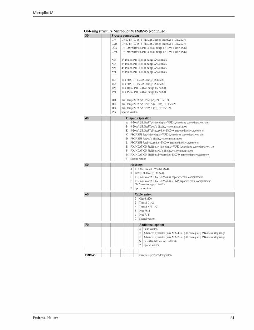
Micropilot M
Endress+Hauser 61
Ordering structure Micropilot M FMR245 (continued)
30 Process connection:
CFK DN50 PN10/16, PTFE>316L flange EN1092-1 (DIN2527)
CMK DN80 PN10/16, PTFE>316L flange EN1092-1 (DIN2527)
CQK DN100 PN10/16, PTFE>316L flange EN1092-1 (DIN2527)
CWK DN150 PN10/16, PTFE>316L flange EN1092-1 (DIN2527)
AEK 2" 150lbs, PTFE>316L flange ANSI B16.5
ALK 3" 150lbs, PTFE>316L flange ANSI B16.5
APK 4" 150lbs, PTFE>316L flange ANSI B16.5
AVK 6" 150lbs, PTFE>316L flange ANSI B16.5
KEK 10K 50A, PTFE>316L flange JIS B2220
KLK 10K 80A, PTFE>316L flange JIS B2220
KPK 10K 100A, PTFE>316L flange JIS B2220
KVK 10K 150A, PTFE>316L flange JIS B2220
TDK Tri-Clamp ISO2852 DN51 (2"), PTFE>316L
TEK Tri-Clamp ISO2852 DN63.5 (2-1/2"), PTFE>316L
TFK Tri-Clamp ISO2852 DN76.1 (3"), PTFE>316L
YY9 Special version
40 Output; Operation:
A 4-20mA SIL HART; 4-line display VU331, envelope curve display on site
B 4-20mA SIL HART; w/o display, via communication
K 4-20mA SIL HART; Prepared for FHX40, remote display (Accessory)
C PROFIBUS PA; 4-line display VU331, envelope curve display on site
D PROFIBUS PA; w/o display, via communication
L PROFIBUS PA; Prepared for FHX40, remote display (Accessory)
E FOUNDATION Fieldbus; 4-line display VU331, envelope curve display on site
F FOUNDATION Fieldbus; w/o display, via communication
M FOUNDATION Fieldbus; Prepared for FHX40, remote display (Accessory)
Y Special version
50 Housing:
A F12 Alu, coated IP65 (NEMA4X)
B F23 316L IP65 (NEMA4X)
C T12 Alu, coated IP65 (NEMA4X), separate conn. compartment
D T12 Alu, coated IP65 (NEMA4X) + OVP, separate conn. compartment,
OVP=overvoltage protection
Y Special version
60 Cable entry:
2 Gland M20
3 Thread G1/2
4 Thread NPT 1/2"
5 Plug M12
6 Plug 7/8"
9 Special version
70 Additional option:
A Basic version
D Advanced dynamics (max MB=40m) (SIL on request) MB=measuring range
F Advanced dynamics (max MB=70m) (SIL on request) MB=measuring range
S GL/ABS/NK marine certificate
Y Special version
FMR245- Complete product designation
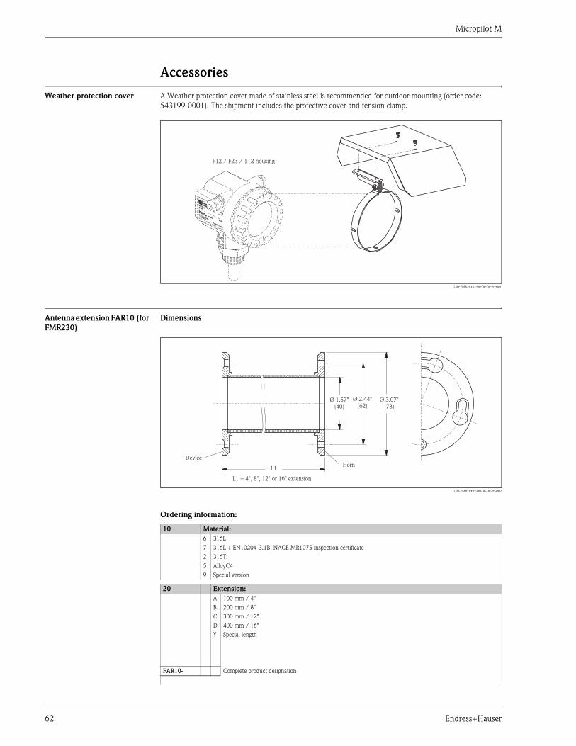
Micropilot M
62 Endress+Hauser
Accessories
Weather protection cover A Weather protection cover made of stainless steel is recommended for outdoor mounting (order code:
543199-0001). The shipment includes the protective cover and tension clamp.
L00-FMR2xxxx-00-00-06-en-001
Antenna extension FAR10 (for
FMR230)
Dimensions
L00-FMRxxxxx-00-00-06-en-002
Ordering information:
ENDRESS+HAUSER
MICROPILOT II
ENDRESS+HAUSER
MICROPILOT II
IP 65IP 65
Order Code:Ser.-No.:
Order Code:Ser.-No.:
MessbereichMeasuring range
MessbereichMeasuring rangeU 16...36 V DC
4...20 mA
U 16...36 V DC4...20 mA
max. 20 m
max. 20 m
Ma
de
in G
erm
any
Ma
ulb
urg
Made in
Germ
any
Maulb
urg
T>70°C :
A
t >85°C
T>70°C :
A
t >85°C
F12 / F23 / T12 housing
10 Material:
6 316L
7 316L + EN10204-3.1B, NACE MR1075 inspection certificate
2 316Ti
5 AlloyC4
9 Special version
20 Extension:
A 100 mm / 4"
B 200 mm / 8"
C 300 mm / 12"
D 400 mm / 16"
Y Special length
FAR10- Complete product designation
L1
L1 = 4", 8", 12" or 16" extension
Device
Horn
Ø 1.57"(40)
Ø 2.44"(62)
Ø 3.07"(78)
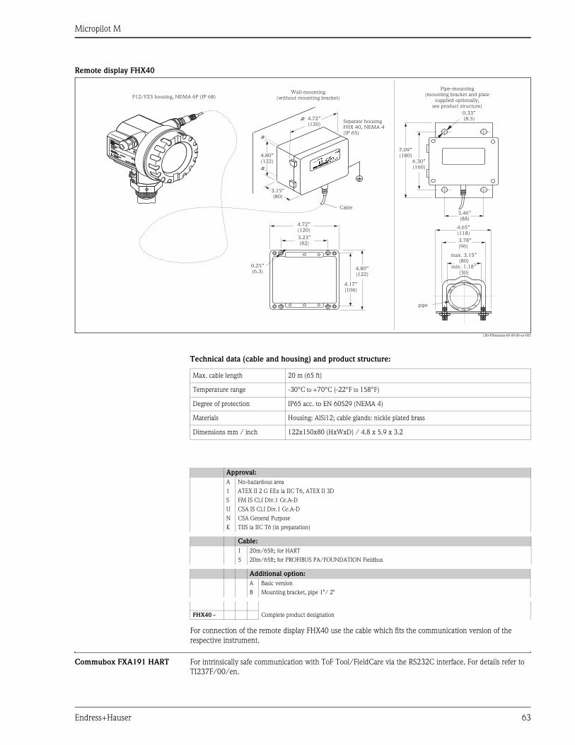
Micropilot M
Endress+Hauser 63
Remote display FHX40
L00-FMxxxxxx-00-00-06-en-003
Technical data (cable and housing) and product structure:
For connection of the remote display FHX40 use the cable which fits the communication version of the
respective instrument.
Commubox FXA191 HART For intrinsically safe communication with ToF Tool/FieldCare via the RS232C interface. For details refer to
TI237F/00/en.
ENDRESS+HAUSER
ENDRESS+HAUSER
IP 65IP 65
Order Code:Ser.-No.:
Order Code:Ser.-No.:
MessbereichMeasuring range
MessbereichMeasuring rangeU 16...36 V DC
4...20 mA
U 16...36 V DC4...20 mA
max. 20 m
max. 20 m
Mad
e in
Ger
man
yM
aulb
urg
Mad
e in
Ger
man
yM
aulb
urg
T>70°C :
A
t >85°C
T>70°C :
A
t >85°C
max. 3.15”(80)
min. 1.18”(30)
3.78”(96)
3.46”(88)
6.30”(160)
0.33”(8.5)
4.65”(118)
7.09”(180)
Separate housingFHX 40, NEMA 4(IP 65)
F12/F23 housing, NEMA 6P (IP 68)
Cable
3.15”(80)
4.80”(122)
4.80”(122)
4.17”(106)
0.25”(6.3)
4.72”(120)
4.72”(120)
3.23”(82)
Wall-mounting(without mounting bracket)
Pipe-mounting(mounting bracket and plate
supplied optionally,see product structure)
pipe
Max. cable length 20 m (65 ft)
Temperature range -30°C to +70°C (-22°F to 158°F)
Degree of protection IP65 acc. to EN 60529 (NEMA 4)
Materials Housing: AlSi12; cable glands: nickle plated brass
Dimensions mm / inch 122x150x80 (HxWxD) / 4.8 x 5.9 x 3.2
Approval:
A Nn-hazardous area
1 ATEX II 2 G EEx ia IIC T6, ATEX II 3D
S FM IS Cl.I Div.1 Gr.A-D
U CSA IS Cl.I Div.1 Gr.A-D
N CSA General Purpose
K TIIS ia IIC T6 (in preparation)
Cable:
1 20m/65ft; for HART
5 20m/65ft; for PROFIBUS PA/FOUNDATION Fieldbus
Additional option:
A Basic version
B Mounting bracket, pipe 1"/ 2"
FHX40 - Complete product designation

Micropilot M
64 Endress+Hauser
Commubox FXA195 HART For intrinsically safe communication with ToF Tool/FieldCare via the USB interface. For details refer to
TI404F/00/en.
Commubox FXA291 The Commubox FXA291 connects Endress+Hauser field instruments with CDI interface (= Endress+Hauser
Common Data Interface) to the USB interface of a personal computer or a notebook. For details refer to
TI405C/07/en.
Note!
For the following Endress+Hauser instruments you need the "ToF Adapter FXA291" as an additional accessory:
• Cerabar S PMC71, PMP7x
• Deltabar S PMD7x, FMD7x
• Deltapilot S FMB70
• Gammapilot M FMG60
• Levelflex M FMP4x
• Micropilot FMR130/FMR131
• Micropilot M FMR2xx
• Micropilot S FMR53x, FMR540
• Prosonic S FMU90
• Prosonic M FMU4x
• Tank Side Monitor NRF590 (with additional adapter cable)
ToF Adapter FXA291 The ToF Adapter FXA291 connects the Commubox FXA291 via the USB interface of a personal computer or
a notebook to the following Endress+Hauser instruments:
• Cerabar S PMC71, PMP7x
• Deltabar S PMD7x, FMD7x
• Deltapilot S FMB70
• Gammapilot M FMG60
• Levelflex M FMP4x
• Micropilot FMR130/FMR131
• Micropilot M FMR2xx
• Micropilot S FMR53x, FMR540
• Prosonic S FMU90
• Prosonic M FMU4x
• Tank Side Monitor NRF590 (with additional adapter cable)
For details refer to KA271F/00/a2.
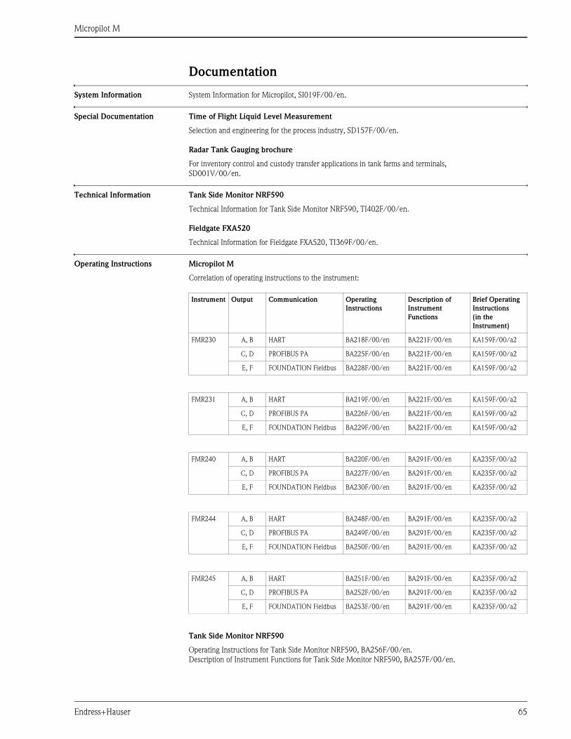
Micropilot M
Endress+Hauser 65
Documentation
System Information System Information for Micropilot, SI019F/00/en.
Special Documentation Time of Flight Liquid Level Measurement
Selection and engineering for the process industry, SD157F/00/en.
Radar Tank Gauging brochure
For inventory control and custody transfer applications in tank farms and terminals,
SD001V/00/en.
Technical Information Tank Side Monitor NRF590
Technical Information for Tank Side Monitor NRF590, TI402F/00/en.
Fieldgate FXA520
Technical Information for Fieldgate FXA520, TI369F/00/en.
Operating Instructions Micropilot M
Correlation of operating instructions to the instrument:
Tank Side Monitor NRF590
Operating Instructions for Tank Side Monitor NRF590, BA256F/00/en.
Description of Instrument Functions for Tank Side Monitor NRF590, BA257F/00/en.
Instrument Output Communication Operating
Instructions
Description of
Instrument
Functions
Brief Operating
Instructions
(in the
Instrument)
FMR230 A, B HART BA218F/00/en BA221F/00/en KA159F/00/a2
C, D PROFIBUS PA BA225F/00/en BA221F/00/en KA159F/00/a2
E, F FOUNDATION Fieldbus BA228F/00/en BA221F/00/en KA159F/00/a2
FMR231 A, B HART BA219F/00/en BA221F/00/en KA159F/00/a2
C, D PROFIBUS PA BA226F/00/en BA221F/00/en KA159F/00/a2
E, F FOUNDATION Fieldbus BA229F/00/en BA221F/00/en KA159F/00/a2
FMR240 A, B HART BA220F/00/en BA291F/00/en KA235F/00/a2
C, D PROFIBUS PA BA227F/00/en BA291F/00/en KA235F/00/a2
E, F FOUNDATION Fieldbus BA230F/00/en BA291F/00/en KA235F/00/a2
FMR244 A, B HART BA248F/00/en BA291F/00/en KA235F/00/a2
C, D PROFIBUS PA BA249F/00/en BA291F/00/en KA235F/00/a2
E, F FOUNDATION Fieldbus BA250F/00/en BA291F/00/en KA235F/00/a2
FMR245 A, B HART BA251F/00/en BA291F/00/en KA235F/00/a2
C, D PROFIBUS PA BA252F/00/en BA291F/00/en KA235F/00/a2
E, F FOUNDATION Fieldbus BA253F/00/en BA291F/00/en KA235F/00/a2
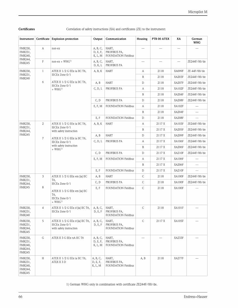
Micropilot M
66 Endress+Hauser
Certificates Correlation of safety instructions (XA) and certificates (ZE) to the instrument:
1) German WHG only in combination with certificate ZE244F/00/de.
Instrument Certificate Explosion protection Output Communication Housing PTB 00 ATEX XA German
WHG
FMR230,
FMR231,
FMR240,
FMR244,
FMR245
A non-ex A, B, C,
D, E, F,
K, L, M
HART,
PROFIBUS PA,
FOUNDATION Fieldbus
— — — —
F non-ex + WHG1) A, B, C,
D, K, L
HART,
PROFIBUS PA
— — — ZE244F/00/de
FMR230,
FMR231,
FMR240
1
6
ATEX II 1/2 G EEx ia IIC T6,
IECEx Zone 0/1
ATEX II 1/2 G EEx ia IIC T6,
IECEx Zone 0/1
+ WHG1)
A, B, K HART A 2118 XA099F ZE 44F/00/de
B 2118 XA203F ZE244F/00/de
A, B HART D 2118 XA207F ZE244F/00/de
C, D, L PROFIBUS PA A 2118 XA102F ZE244F/00/de
B 2118 XA204F ZE244F/00/de
C, D PROFIBUS PA D 2118 XA208F ZE244F/00/de
E, F, M FOUNDATION Fieldbus A 2118 XA102F —
B 2118 XA204F —
E, F FOUNDATION Fieldbus D 2118 XA208F —
FMR230,
FMR231,
FMR244,
FMR245
2
7
ATEX II 1/2 G EEx ia IIC T6,
IECEx Zone 0/1
with safety instruction
ATEX II 1/2 G EEx ia IIC T6,
IECEx Zone 0/1
with safety instruction
+ WHG1)
A, B, K HART A 2117 X XA103F ZE244F/00/de
B 2117 X XA205F ZE244F/00/de
A, B HART D 2117 X XA209F ZE244F/00/de
C, D, L PROFIBUS PA A 2117 X XA106F ZE244F/00/de
B 2117 X XA206F ZE244F/00/de
C, D PROFIBUS PA D 2117 X XA210F ZE244F/00/de
E, F, M FOUNDATION Fieldbus A 2117 X XA106F —
B 2117 X XA206F —
E, F FOUNDATION Fieldbus D 2117 X XA210F —
FMR230,
FMR231,
FMR244,
FMR245
3
8
ATEX II 1/2 G EEx em [ia] IIC
T6,
IECEx Zone 0/1
ATEX II 1/2 G EEx em [ia] IIC
T6,
IECEx Zone 0/1
+ WHG1)
A, B HART C 2118 XA100F ZE244F/00/de
C, D PROFIBUS PA C 2118 XA100F ZE244F/00/de
E, F FOUNDATION Fieldbus C 2118 XA100F —
FMR230,
FMR231,
FMR240
4 ATEX II 1/2 G EEx d [ia] IIC T6,
IECEx Zone 0/1
A, B, C,
D, E, F
HART,
PROFIBUS PA,
FOUNDATION Fieldbus
C 2118 XA101F —
FMR230,
FMR231,
FMR244,
FMR245
5 ATEX II 1/2 G EEx d [ia] IIC T6,
IECEx Zone 0/1
with safety instruction
A, B, C,
D, E, F
HART,
PROFIBUS PA,
FOUNDATION Fieldbus
C 2117 X XA105F —
FMR230,
FMR231,
FMR240,
FMR244,
FMR245
G ATEX II 3 G EEx nA IIC T6 A, B, C,
D, E, F,
K, L, M
HART,
PROFIBUS PA,
FOUNDATION Fieldbus
— — XA233F —
FMR230,
FMR231,
FMR240,
FMR244,
FMR245
H ATEX II 1/2 G EEx ia IIC T6,
ATEX II 3 D
A, B, C,
D, E, F,
K, L, M
HART,
PROFIBUS PA,
FOUNDATION Fieldbus
A, B 2118 XA277F —
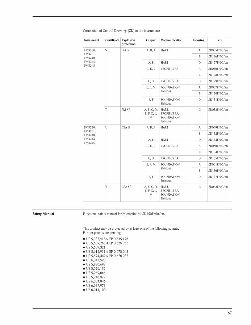
67
Correlation of Control Drawings (ZD) to the instrument:
Safety Manual Functional safety manual for Micropilot M, SD150F/00/en.
This product may be protected by at least one of the following patents.
Further patents are pending.
• US 5,387,918 i EP 0 535 196
• US 5,689,265 i EP 0 626 063
• US 5,659,321
• US 5,614,911 i EP 0 670 048
• US 5,594,449 i EP 0 676 037
• US 6,047,598
• US 5,880,698
• US 5,926,152
• US 5,969,666
• US 5,948,979
• US 6,054,946
• US 6,087,978
• US 6,014,100
Instrument Certificate Explosion
protection
Output Communication Housing ZD
FMR230,
FMR231,
FMR240,
FMR244,
FMR245
S FM IS A, B, K HART A ZD055F/00/en
B ZD126F/00/en
A, B HART D ZD127F/00/en
C, D, L PROFIBUS PA A ZD056F/00/en
B ZD128F/00/en
C, D PROFIBUS PA D ZD129F/00/en
E, F, M FOUNDATION
Fieldbus
A ZD057F/00/en
B ZD130F/00/en
E, F FOUNDATION
Fieldbus
D ZD131F/00/en
T FM XP A, B, C, D,
E, F, K, L,
M
HART,
PROFIBUS PA,
FOUNDATION
Fieldbus
C ZD058F/00/en
FMR230,
FMR231,
FMR240,
FMR244,
FMR245
U CSA IS A, B, K HART A ZD059F/00/en
B ZD132F/00/en
A, B HART D ZD133F/00/en
C, D, L PROFIBUS PA A ZD060F/00/en
B ZD134F/00/en
C, D PROFIBUS PA D ZD135F/00/en
E, F, M FOUNDATION
Fieldbus
A ZD061F/00/en
B ZD136F/00/en
E, F FOUNDATION
Fieldbus
D ZD137F/00/en
V CSA XP A, B, C, D,
E, F, K, L,
M
HART,
PROFIBUS PA,
FOUNDATION
Fieldbus
C ZD062F/00/en

68
United States
Endress+Hauser, Inc.
2350 Endress Place
Greenwood, IN 46143
Tel. 317-535-7138
Sales 888-ENDRESS
Service 800-642-8737
Fax 317-535-8498
www.us.endress.com
TI345F/24/ae/09.06
© 2006 Endress+Hauser, Inc.
Canada
Endress+Hauser Canada
1075 Sutton Drive
Burlington, ON L7L 5Z8
Tel. 905-681-9292
800-668-3199
Fax 905-681-9444
www.ca.endress.com
Mexico
Endress+Hauser, México, S.A. de C.V.
Av. Gustavo Baz No. 43
Fracc. Bosques de Echegaray
Naucalpan de Juárez, C.P. 53310, Estado
de México
México
Tel: (52) 55-5371-1110
Fax (52) 55-5371-1128