Embed Size (px)
Citation preview
Technical Information
Note No. 5
Cycle network signing
Issue date: November 2008 Issue level: 02
Owned by: Technical Director Contact: [email protected]
2 Signing guidance
Sustrans is the UK’s leading sustainable transport charity.
Our vision is a world in which people choose to travel in ways that benefit their health and the
environment. We work on practical, innovative solutions to the transport challenges facing us all.
Sustrans is the charity behind the award winning National Cycle Network, Safe Routes to Schools,
Bike It, TravelSmart, Active Travel, Connect2 and Liveable Neighbourhoods, all projects that are
changing our world one mile at a time.
To find out more visit or call: www.sustrans.org.uk 0845 113 00 65
Head Office
Sustrans
2 Cathedral Square
College Green
Bristol
BS1 5DD
© Sustrans November 2008
Registered Charity No. 326550 (England and Wales) SC039263 (Scotland)
VAT Registration No. 416740656
All photos by Sustrans except where noted otherwise.
November 2008 3
Table of contents
1. Signing of cycle networks ........................................................................................................... 5
1.1. Introduction ......................................................................................................................... 5
1.2. Signing of cycle networks.................................................................................................... 5
1.3. Health and Safety ................................................................................................................ 5
1.4. Legal information ................................................................................................................. 6
2. Direction Signs ............................................................................................................................ 7
2.1. Direction signs..................................................................................................................... 7
2.2. Types of direction signs....................................................................................................... 7
2.3. Road markings .................................................................................................................... 9
2.4. National Cycle Network route numbers ............................................................................. 10
2.5. Destinations....................................................................................................................... 11
2.6. Sign locations .................................................................................................................... 12
2.7. Tourism signs .................................................................................................................... 14
2.8. Information boards, mileposts and combined route signs ................................................. 15
3. Other cycle signs....................................................................................................................... 16
3.1. Shared pedestrian and cycle paths ................................................................................... 16
3.2. Pedestrian Zones............................................................................................................... 17
3.3. Home zones ...................................................................................................................... 19
3.4. Cycle lanes ........................................................................................................................ 20
3.5. Cycling against motor traffic flow ...................................................................................... 23
3.6. Junction diagrams ............................................................................................................. 25
3.7. Advanced stop lines .......................................................................................................... 25
3.8. Cycle parking..................................................................................................................... 26
3.9. Warning sign...................................................................................................................... 27
3.10. Cycle prohibition............................................................................................................ 28
3.11. Signs not to be used...................................................................................................... 28
4. Technical details........................................................................................................................ 31
4 Signing guidance
4.1. Locating signs ................................................................................................................... 31
4.2. Dimension from highway and cycle path ........................................................................... 31
4.3. Putting up signs................................................................................................................. 32
4.4. Text and sign size.............................................................................................................. 32
4.4.1. Signs with text................................................................................................................ 32
4.4.2. Signs without text........................................................................................................... 33
4.5. Sign specification .............................................................................................................. 34
4.6. Lighting.............................................................................................................................. 34
4.7. Sign posts ......................................................................................................................... 35
4.8. Road markings .................................................................................................................. 37
5. Additional Information ............................................................................................................... 38
5.1. Temporary Diversion Signs................................................................................................ 38
5.2. Seasonal routes and other fixed route alternatives ............................................................ 38
5.3. Cycle events ...................................................................................................................... 39
5.4. Bilingual signs.................................................................................................................... 39
5.5. Sustrans Ranger signs....................................................................................................... 39
6. How to plan and order signs ..................................................................................................... 41
7. Sign surveys.............................................................................................................................. 42
8. Appendix A - Overview of signs ................................................................................................ 44
9. Appendix B – Example signing schedule................................................................................... 46
10. Appendix C - Examples of sign ordering sheets.................................................................... 47
10.1. Direction signs ............................................................................................................... 47
10.2. Confirmation signs......................................................................................................... 48
10.3. Other signs .................................................................................................................... 49
11. Appendix C – Sample sign surveying sheet........................................................................... 50
12. Appendix D – Sign surveying outcomes ................................................................................ 51
13. References ............................................................................................................................ 53
November 2008 5
1. Signing of cycle networks
1.1. Introduction
This information has been prepared to provide assistance for people involved with signing cycle and
shared use routes and links within a cycle network. In particular, it offers guidance on
• The recommended standard of signs
• The signs required and where they should be located
• The monitoring and maintenance of signs
• Sign posts and sign board details
This information is based on Sustrans’ extensive experience with developing the National Cycle
Network and statutory regulations and guidance.
1.2. Signing of cycle networks
One of the key requirements in developing safe and attractive places to cycle is comprehensive
direction signing that links paths, tracks, lanes and roads together that make up the network. The
attractiveness and utility of any network to potential users will, in part, depend on the quality,
coherence, consistency and frequency of the signs. Inadequate, missing or misleading signage is the
main concern expressed by users on a network. Visitors and local residents should be able to follow
all routes in any direction, without needing a map.
Signing advertises the presence of cyclists to other road users and advises them that there is an
alternative to using the car. Cohesive and continuous signing of a route or network gives first–time
users a good impression of the area, and encourages further exploration.
Signing should be appropriate to the user and the location. Too many signs or signs that are too
large may add little or nothing the cycling experience but clutter views and streetscapes. Cycle path
surface painting is a useful alternative to post–mounted signing and usually only one or the other is
required.
1.3. Health and Safety
Good signing of a cycle route can enhance the safety of the cyclist using the route. Signs will warn
the user of hidden dangers that are not otherwise perceptible. Obvious dangers need not normally
be signed.
Signs should help cyclists to safely get from the start of their journey to the desired destination while
riding their bicycle, while steering cyclists away from dangerous areas.
Signposts too close to a path or signs overhanging a route can form obstacles for cyclists and must
be avoided.
6 Signing guidance
1.4. Legal information
Signs (called diagrams) for cycle routes on highways are included in the DfT Traffic Signs
Regulations & General Directions (TSRGD) 2002 (for England, Wales, Scotland and the Isle of Man),
the Traffic Signs Regulations (Northern Ireland) 1997 and the DfT Traffic Signs Manual (for England,
Wales, Scotland and Northern Ireland) – together subsequently referred to as “Highway Sign
Regulations”.
Usually only signs included in statutory guidance are permitted for use on cycle routes on roads
however DfT approval can be obtained for using alternative signs for particular locations (the
Transport Directorate in Scotland and Transport Wales for Wales will do this in their areas). Some
local authorities depart from statutory guidance without obtaining DfT approval on the grounds of
safety, using common sense and being specific to local situations.
Traffic regulation orders (referred to as “TRO”) are sometimes required to implement signs on
highways (generally where vehicle restrictions are imposed). These are issued by highway
authorities. TROs can be “permanent”, “temporary” (usually up to 18 months, e.g. for construction
works) or “experimental” (where the public response to the effects of the order needs to be
evaluated). The London Cycling Design Standards (see references) have more information on this
procedure.
Off-road, i.e. along canals, in parks or crossing private land, in principle any sign may be used with
the approval of the land owner. This gives the opportunity to use standard highway signs or
variations or other types of signs like mileposts, local maps etc. Anybody who has approval from the
land owner may put up signs away from highways.
November 2008 7
2. Direction Signs
2.1. Direction signs
It is essential that at frequent locations along any cycle route signs advertise key destinations and
distances. Ideally, two main destinations should be given, directing the cyclist to locations close by
or to major destinations within a reasonable cycling distance. Typically, these will be the next village
and town. In larger urban areas signs should point to known landmarks, which may be parks,
squares, public spaces or even pubs or cinemas (see section 2.5).
Consistency and clarity in the choice of destination is important. The London Cycle Design Standard
includes a list of destinations signs normally point too, and setting up such a list is encouraged for
other dense areas as well.
Cycling distances should be measured accurately along each leg of the network, and to defined
points (e.g. “Hyde Park” is an area over 1½ miles wide by ¾ miles long and not suitable, whereas
“Speaker’s Corner” is a defined location). Where distances are measured to “town centre”, then a
defined landmark (e.g. the main town square or the town hall or railway station) must be determined
and consistently used. Points where distances are measured to must be reached by a continuously
signed cycle route.
2.2. Types of direction signs
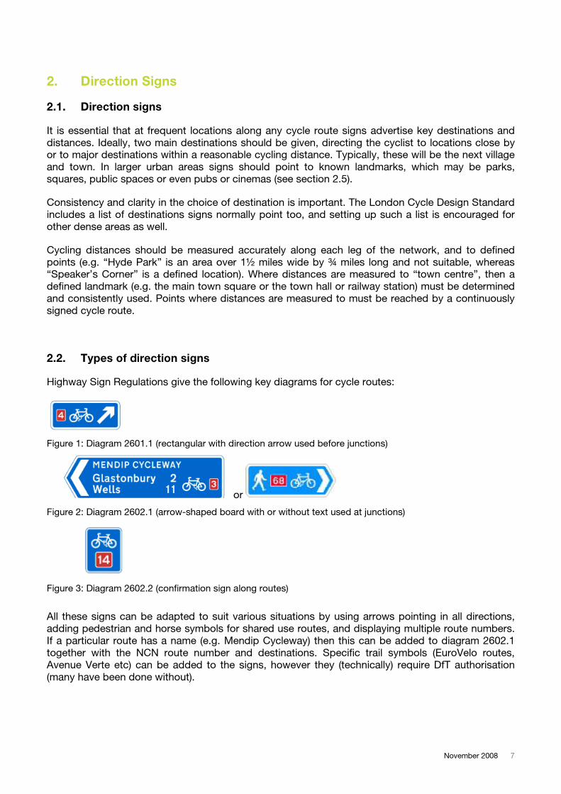
Highway Sign Regulations give the following key diagrams for cycle routes:
Figure 1: Diagram 2601.1 (rectangular with direction arrow used before junctions)
or
Figure 2: Diagram 2602.1 (arrow-shaped board with or without text used at junctions)
Figure 3: Diagram 2602.2 (confirmation sign along routes)
All these signs can be adapted to suit various situations by using arrows pointing in all directions,
adding pedestrian and horse symbols for shared use routes, and displaying multiple route numbers.
If a particular route has a name (e.g. Mendip Cycleway) then this can be added to diagram 2602.1
together with the NCN route number and destinations. Specific trail symbols (EuroVelo routes,
Avenue Verte etc) can be added to the signs, however they (technically) require DfT authorisation
(many have been done without).
8 Signing guidance
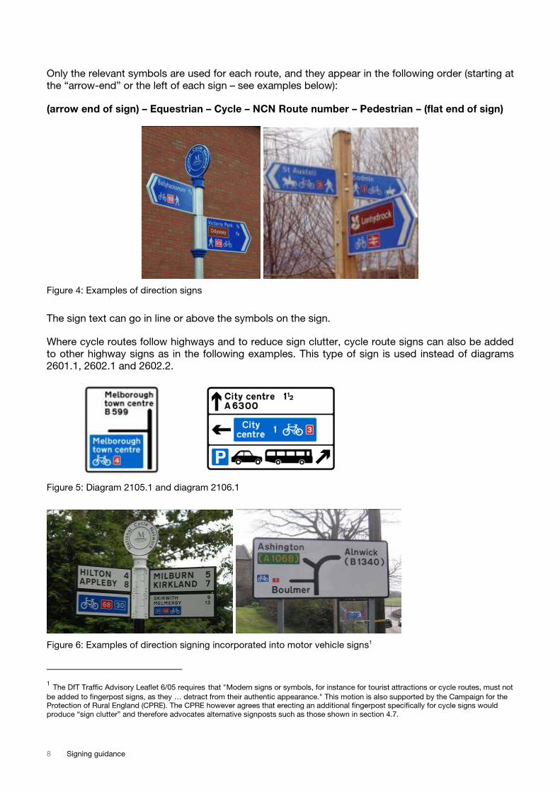
Only the relevant symbols are used for each route, and they appear in the following order (starting at
the “arrow-end” or the left of each sign – see examples below):
(arrow end of sign) – Equestrian – Cycle – NCN Route number – Pedestrian – (flat end of sign)
Figure 4: Examples of direction signs
The sign text can go in line or above the symbols on the sign.
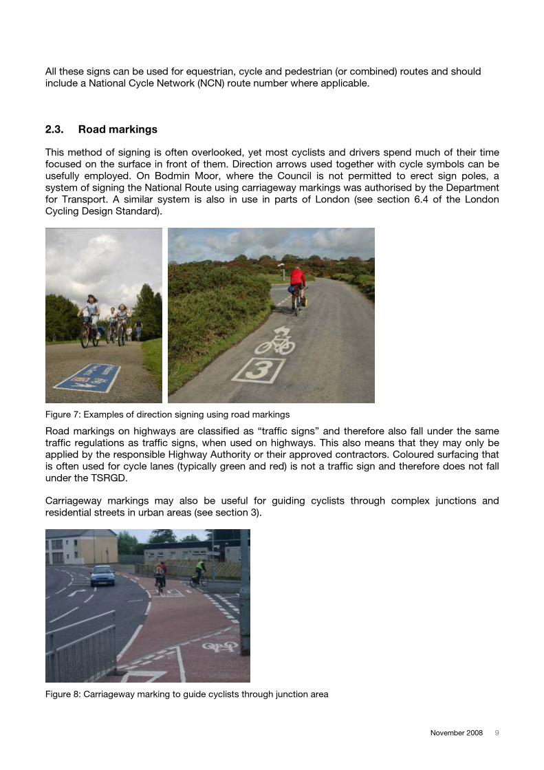
Where cycle routes follow highways and to reduce sign clutter, cycle route signs can also be added
to other highway signs as in the following examples. This type of sign is used instead of diagrams
2601.1, 2602.1 and 2602.2.
Figure 5: Diagram 2105.1 and diagram 2106.1
Figure 6: Examples of direction signing incorporated into motor vehicle signs1
1 The DfT Traffic Advisory Leaflet 6/05 requires that "Modern signs or symbols, for instance for tourist attractions or cycle routes, must not be added to fingerpost signs, as they … detract from their authentic appearance." This motion is also supported by the Campaign for the Protection of Rural England (CPRE). The CPRE however agrees that erecting an additional fingerpost specifically for cycle signs would
produce “sign clutter” and therefore advocates alternative signposts such as those shown in section 4.7.
November 2008 9
All these signs can be used for equestrian, cycle and pedestrian (or combined) routes and should
include a National Cycle Network (NCN) route number where applicable.
2.3. Road markings
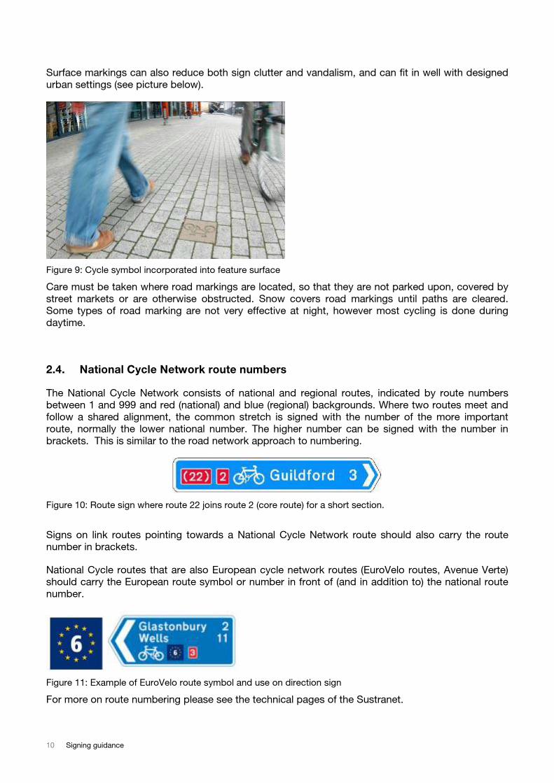
This method of signing is often overlooked, yet most cyclists and drivers spend much of their time
focused on the surface in front of them. Direction arrows used together with cycle symbols can be
usefully employed. On Bodmin Moor, where the Council is not permitted to erect sign poles, a
system of signing the National Route using carriageway markings was authorised by the Department
for Transport. A similar system is also in use in parts of London (see section 6.4 of the London
Cycling Design Standard).
Figure 7: Examples of direction signing using road markings
Road markings on highways are classified as “traffic signs” and therefore also fall under the same
traffic regulations as traffic signs, when used on highways. This also means that they may only be
applied by the responsible Highway Authority or their approved contractors. Coloured surfacing that
is often used for cycle lanes (typically green and red) is not a traffic sign and therefore does not fall
under the TSRGD.
Carriageway markings may also be useful for guiding cyclists through complex junctions and
residential streets in urban areas (see section 3).
Figure 8: Carriageway marking to guide cyclists through junction area
10 Signing guidance
Surface markings can also reduce both sign clutter and vandalism, and can fit in well with designed
urban settings (see picture below).
Figure 9: Cycle symbol incorporated into feature surface
Care must be taken where road markings are located, so that they are not parked upon, covered by
street markets or are otherwise obstructed. Snow covers road markings until paths are cleared.
Some types of road marking are not very effective at night, however most cycling is done during
daytime.
2.4. National Cycle Network route numbers
The National Cycle Network consists of national and regional routes, indicated by route numbers
between 1 and 999 and red (national) and blue (regional) backgrounds. Where two routes meet and
follow a shared alignment, the common stretch is signed with the number of the more important
route, normally the lower national number. The higher number can be signed with the number in
brackets. This is similar to the road network approach to numbering.
Figure 10: Route sign where route 22 joins route 2 (core route) for a short section.
Signs on link routes pointing towards a National Cycle Network route should also carry the route
number in brackets.
National Cycle routes that are also European cycle network routes (EuroVelo routes, Avenue Verte)
should carry the European route symbol or number in front of (and in addition to) the national route
number.
Figure 11: Example of EuroVelo route symbol and use on direction sign
For more on route numbering please see the technical pages of the Sustranet.
November 2008 11
2.5. Destinations
Destination signs typically include one to three lines of text. This can be either one line displaying a
particular route name (e.g. Wem Brook Trail) followed by one or two destinations along the route, or
up to three destinations along the route without a route name. Route names are printed in upper
case letters for signs located on the named route, and with lower case letters for signs pointing
towards a named route. It is important that all destinations indicated on the sign can actually be
reached along continuously signed cycle routes, and that the indicated destination text does not
change until the destination is reached.
Figure 12: Signposting towards local streets from cycle route in park
In urban areas prominent locations (e.g. “George Elliot Hospital” or “Cathedral”) or districts (e.g.
“Digbeth” or “City Centre”) are indicated. It is useful to indicate street names on links from a route
that does not otherwise provide mapped orientation points (e.g. parks or canals – see example
above).
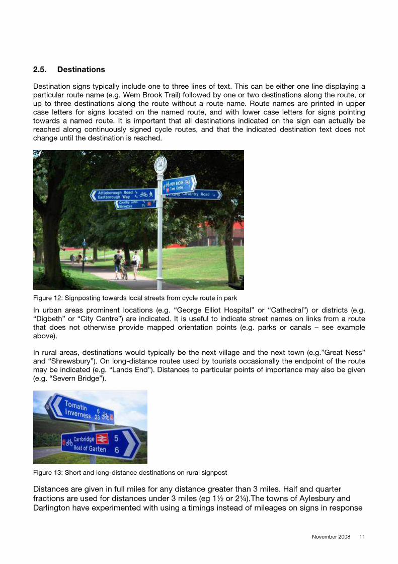
In rural areas, destinations would typically be the next village and the next town (e.g.”Great Ness”
and “Shrewsbury”). On long-distance routes used by tourists occasionally the endpoint of the route
may be indicated (e.g. “Lands End”). Distances to particular points of importance may also be given
(e.g. “Severn Bridge”).
Figure 13: Short and long-distance destinations on rural signpost
Distances are given in full miles for any distance greater than 3 miles. Half and quarter
fractions are used for distances under 3 miles (eg 1½ or 2¼).The towns of Aylesbury and
Darlington have experimented with using a timings instead of mileages on signs in response
12 Signing guidance
to feedback that non-cyclists tend to overestimate how long it takes to cycle a trip. In both
cases, timings were approximated for a family cycling the route, and thus are inaccurate for
faster commuter cyclists.
2.6. Sign locations
It is particularly important that the public know which way to turn at any junction along routes. Along
all routes, care must be taken to ensure that satisfactory signing is useful for travelling in any
direction along a route, and there should also be signs indicating directions for those cyclists joining
a route.
The frequency and location of signs should take account of the ability of cyclists to follow the route
should any one sign go missing. Care should be taken to locate all signs so that they are clearly
visible and legible to approaching cyclists, who can then prepare to make the appropriate
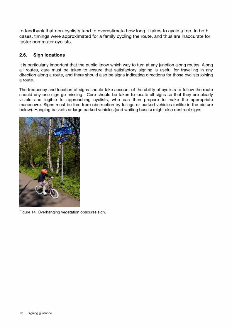
manoeuvre. Signs must be free from obstruction by foliage or parked vehicles (unlike in the picture
below). Hanging baskets or large parked vehicles (and waiting buses) might also obstruct signs.
Figure 14: Overhanging vegetation obscures sign.
November 2008 13
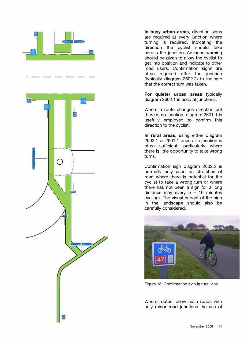
In busy urban areas, direction signs
are required at every junction where
turning is required, indicating the
direction the cyclist should take
across the junction. Advance warning
should be given to allow the cyclist to
get into position and indicate to other
road users. Confirmation signs are
often required after the junction
(typically diagram 2602.2) to indicate
that the correct turn was taken.
For quieter urban areas typically
diagram 2602.1 is used at junctions.
Where a route changes direction but
there is no junction, diagram 2601.1 is
usefully employed to confirm this
direction to the cyclist.
In rural areas, using either diagram
2602.1 or 2601.1 once at a junction is
often sufficient, particularly where
there is little opportunity to take wrong
turns.
Confirmation sign diagram 2602.2 is
normally only used on stretches of
road where there is potential for the
cyclist to take a wrong turn or where
there has not been a sign for a long
distance (say every 5 – 10 minutes
cycling). The visual impact of the sign
in the landscape should also be
carefully considered.
Figure 15: Confirmation sign in rural lane
Where routes follow main roads with
only minor road junctions the use of
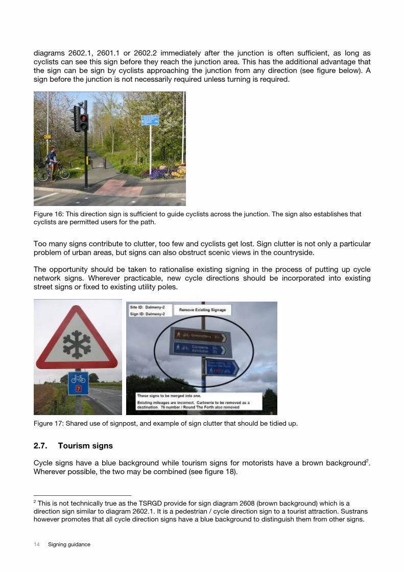
14 Signing guidance
diagrams 2602.1, 2601.1 or 2602.2 immediately after the junction is often sufficient, as long as
cyclists can see this sign before they reach the junction area. This has the additional advantage that
the sign can be sign by cyclists approaching the junction from any direction (see figure below). A
sign before the junction is not necessarily required unless turning is required.
Figure 16: This direction sign is sufficient to guide cyclists across the junction. The sign also establishes that
cyclists are permitted users for the path.
Too many signs contribute to clutter, too few and cyclists get lost. Sign clutter is not only a particular
problem of urban areas, but signs can also obstruct scenic views in the countryside.
The opportunity should be taken to rationalise existing signing in the process of putting up cycle
network signs. Wherever practicable, new cycle directions should be incorporated into existing
street signs or fixed to existing utility poles.
Figure 17: Shared use of signpost, and example of sign clutter that should be tidied up.
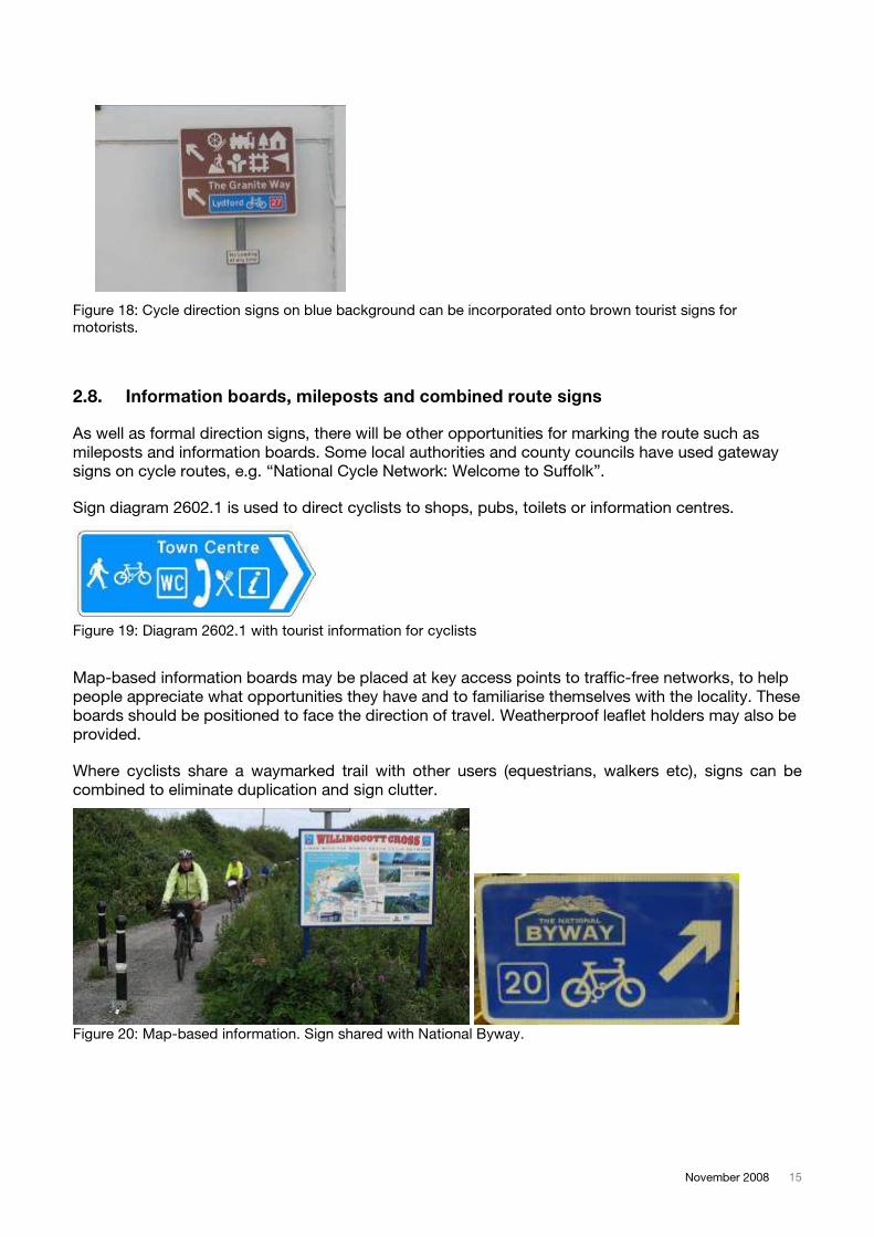
2.7. Tourism signs
Cycle signs have a blue background while tourism signs for motorists have a brown background2.
Wherever possible, the two may be combined (see figure 18).
2 This is not technically true as the TSRGD provide for sign diagram 2608 (brown background) which is a
direction sign similar to diagram 2602.1. It is a pedestrian / cycle direction sign to a tourist attraction. Sustrans
however promotes that all cycle direction signs have a blue background to distinguish them from other signs.
November 2008 15
Figure 18: Cycle direction signs on blue background can be incorporated onto brown tourist signs for
motorists.
2.8. Information boards, mileposts and combined route signs
As well as formal direction signs, there will be other opportunities for marking the route such as
mileposts and information boards. Some local authorities and county councils have used gateway
signs on cycle routes, e.g. “National Cycle Network: Welcome to Suffolk”.
Sign diagram 2602.1 is used to direct cyclists to shops, pubs, toilets or information centres.
Figure 19: Diagram 2602.1 with tourist information for cyclists
Map-based information boards may be placed at key access points to traffic-free networks, to help
people appreciate what opportunities they have and to familiarise themselves with the locality. These
boards should be positioned to face the direction of travel. Weatherproof leaflet holders may also be
provided.
Where cyclists share a waymarked trail with other users (equestrians, walkers etc), signs can be
combined to eliminate duplication and sign clutter.
Figure 20: Map-based information. Sign shared with National Byway.
16 Signing guidance
3. Other cycle signs
3.1. Shared pedestrian and cycle paths
There are many instances where cyclists and pedestrians share routes where motorised vehicles are
not permitted. In most cases it is sufficient to indicate traffic free cycle routes simply by using cycle
specific blue direction signs (as shown in section 2). Only where cycle routes follow what might be
otherwise mistaken as a highway or footway it might be necessary to put up a sign indicating shared
or sole use by pedestrians and / or cyclists as appropriate3.
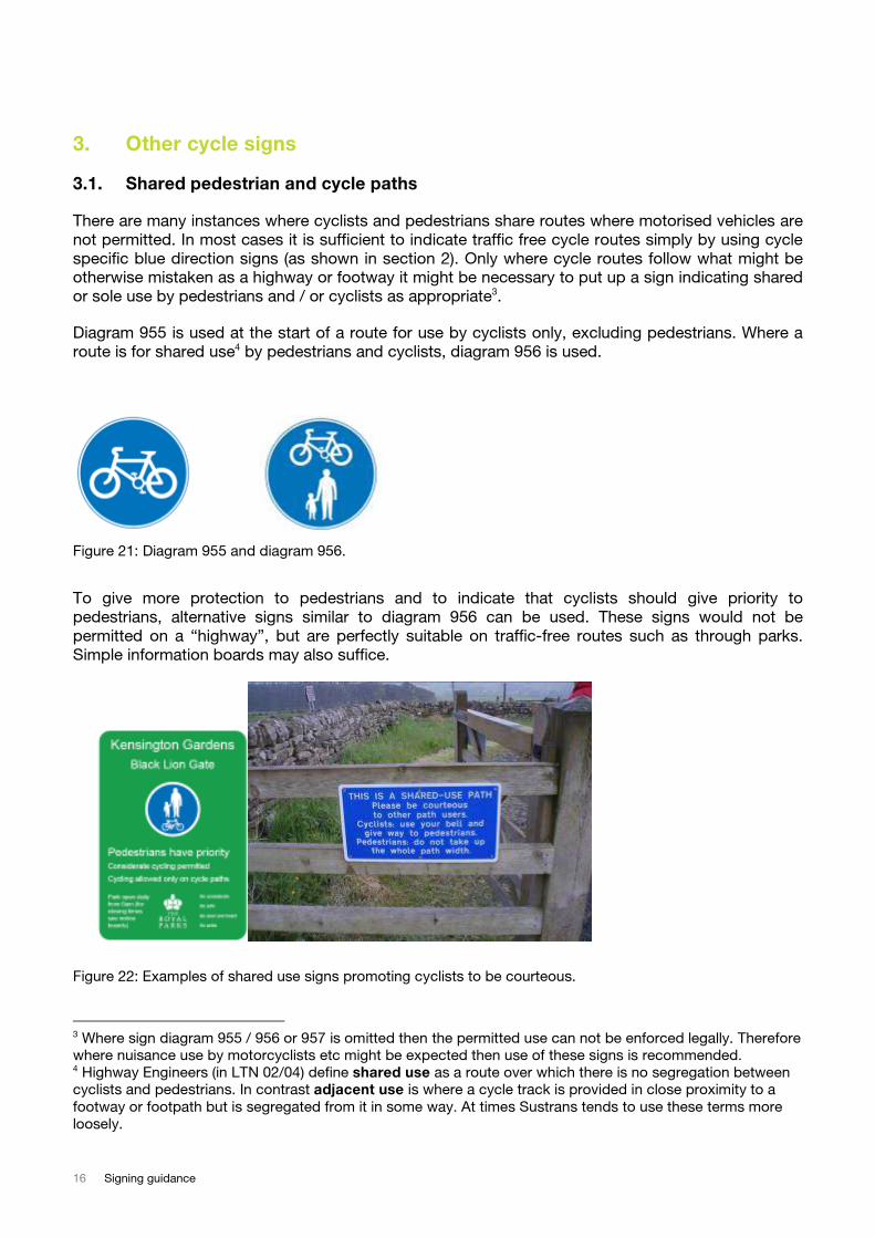
Diagram 955 is used at the start of a route for use by cyclists only, excluding pedestrians. Where a
route is for shared use4 by pedestrians and cyclists, diagram 956 is used.
Figure 21: Diagram 955 and diagram 956.
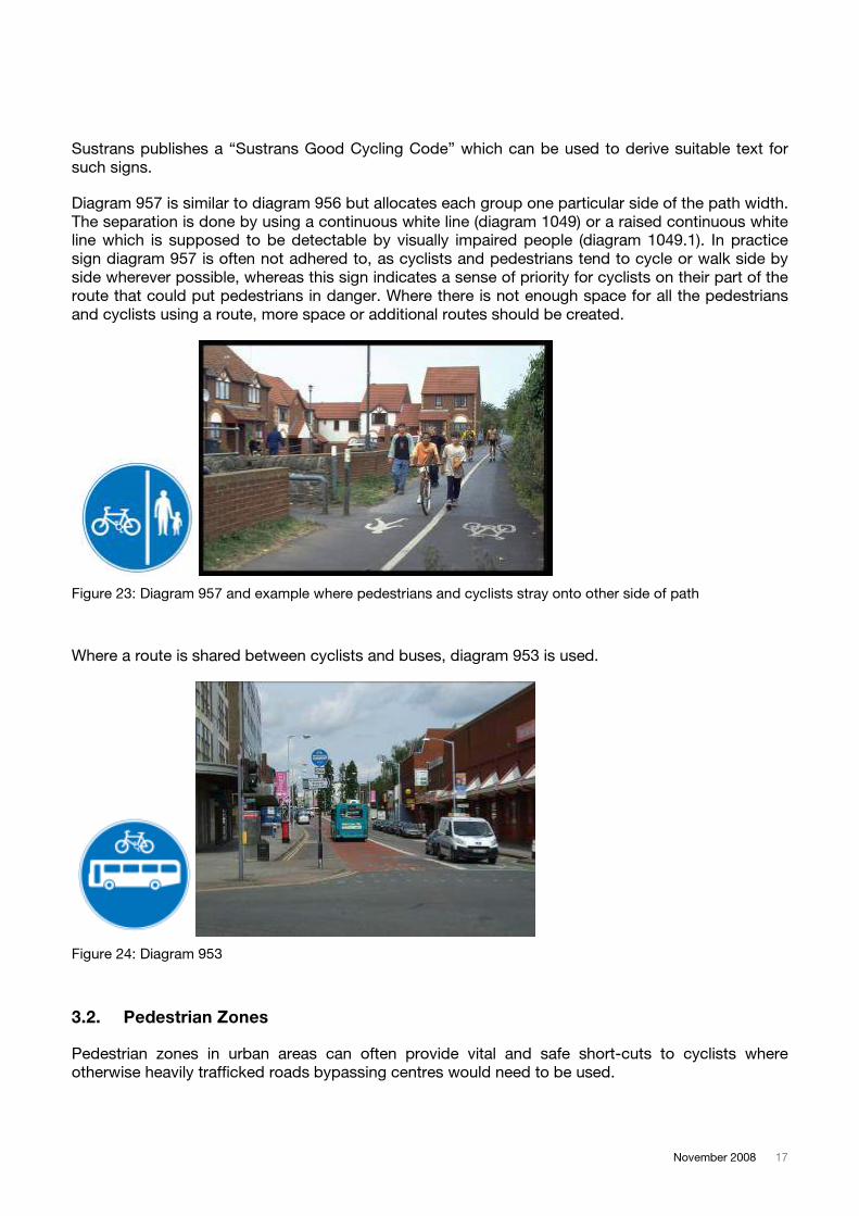
To give more protection to pedestrians and to indicate that cyclists should give priority to
pedestrians, alternative signs similar to diagram 956 can be used. These signs would not be
permitted on a “highway”, but are perfectly suitable on traffic-free routes such as through parks.
Simple information boards may also suffice.
Figure 22: Examples of shared use signs promoting cyclists to be courteous.
3 Where sign diagram 955 / 956 or 957 is omitted then the permitted use can not be enforced legally. Therefore
where nuisance use by motorcyclists etc might be expected then use of these signs is recommended. 4 Highway Engineers (in LTN 02/04) define shared use as a route over which there is no segregation between
cyclists and pedestrians. In contrast adjacent use is where a cycle track is provided in close proximity to a
footway or footpath but is segregated from it in some way. At times Sustrans tends to use these terms more
loosely.
November 2008 17
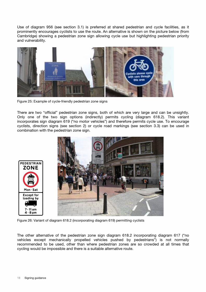
Sustrans publishes a “Sustrans Good Cycling Code” which can be used to derive suitable text for
such signs.
Diagram 957 is similar to diagram 956 but allocates each group one particular side of the path width.
The separation is done by using a continuous white line (diagram 1049) or a raised continuous white
line which is supposed to be detectable by visually impaired people (diagram 1049.1). In practice
sign diagram 957 is often not adhered to, as cyclists and pedestrians tend to cycle or walk side by
side wherever possible, whereas this sign indicates a sense of priority for cyclists on their part of the
route that could put pedestrians in danger. Where there is not enough space for all the pedestrians
and cyclists using a route, more space or additional routes should be created.
Figure 23: Diagram 957 and example where pedestrians and cyclists stray onto other side of path
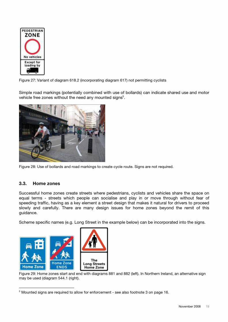
Where a route is shared between cyclists and buses, diagram 953 is used.
Figure 24: Diagram 953
3.2. Pedestrian Zones
Pedestrian zones in urban areas can often provide vital and safe short-cuts to cyclists where
otherwise heavily trafficked roads bypassing centres would need to be used.
18 Signing guidance
Use of diagram 956 (see section 3.1) is preferred at shared pedestrian and cycle facilities, as it
prominently encourages cyclists to use the route. An alternative is shown on the picture below (from
Cambridge) showing a pedestrian zone sign allowing cycle use but highlighting pedestrian priority
and vulnerability.
Figure 25: Example of cycle-friendly pedestrian zone signs
There are two “official” pedestrian zone signs, both of which are very large and can be unsightly.
Only one of the two sign options (indirectly) permits cycling (diagram 618.2). This variant
incorporates sign diagram 619 (“no motor vehicles”) and therefore permits cycle use. To encourage
cyclists, direction signs (see section 2) or cycle road markings (see section 3.3) can be used in
combination with the pedestrian zone sign.
Figure 26: Variant of diagram 618.2 (incorporating diagram 619) permitting cyclists
The other alternative of the pedestrian zone sign diagram 618.2 incorporating diagram 617 (“no
vehicles except mechanically propelled vehicles pushed by pedestrians”) is not normally
recommended to be used, other than where pedestrian zones are so crowded at all times that
cycling would be impossible and there is a suitable alternative route.
November 2008 19
Figure 27: Variant of diagram 618.2 (incorporating diagram 617) not permitting cyclists
Simple road markings (potentially combined with use of bollards) can indicate shared use and motor
vehicle free zones without the need any mounted signs5.
Figure 28: Use of bollards and road markings to create cycle route. Signs are not required.
3.3. Home zones
Successful home zones create streets where pedestrians, cyclists and vehicles share the space on
equal terms - streets which people can socialise and play in or move through without fear of
speeding traffic, having as a key element a street design that makes it natural for drivers to proceed
slowly and carefully. There are many design issues for home zones beyond the remit of this
guidance.
Scheme specific names (e.g. Long Street in the example below) can be incorporated into the signs.
Figure 29: Home zones start and end with diagrams 881 and 882 (left). In Northern Ireland, an alternative sign
may be used (diagram 544.1 (right).
5 Mounted signs are required to allow for enforcement - see also footnote 3 on page 16.
20 Signing guidance
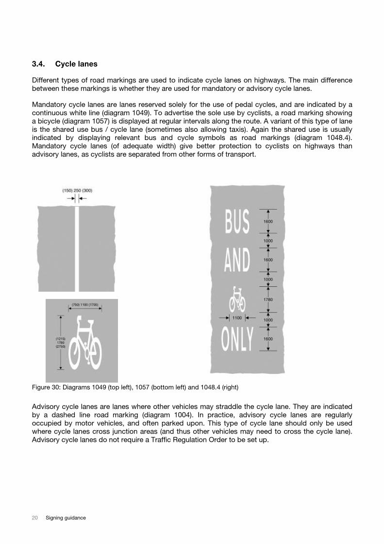
3.4. Cycle lanes
Different types of road markings are used to indicate cycle lanes on highways. The main difference
between these markings is whether they are used for mandatory or advisory cycle lanes.
Mandatory cycle lanes are lanes reserved solely for the use of pedal cycles, and are indicated by a
continuous white line (diagram 1049). To advertise the sole use by cyclists, a road marking showing
a bicycle (diagram 1057) is displayed at regular intervals along the route. A variant of this type of lane
is the shared use bus / cycle lane (sometimes also allowing taxis). Again the shared use is usually
indicated by displaying relevant bus and cycle symbols as road markings (diagram 1048.4).
Mandatory cycle lanes (of adequate width) give better protection to cyclists on highways than
advisory lanes, as cyclists are separated from other forms of transport.
Figure 30: Diagrams 1049 (top left), 1057 (bottom left) and 1048.4 (right)
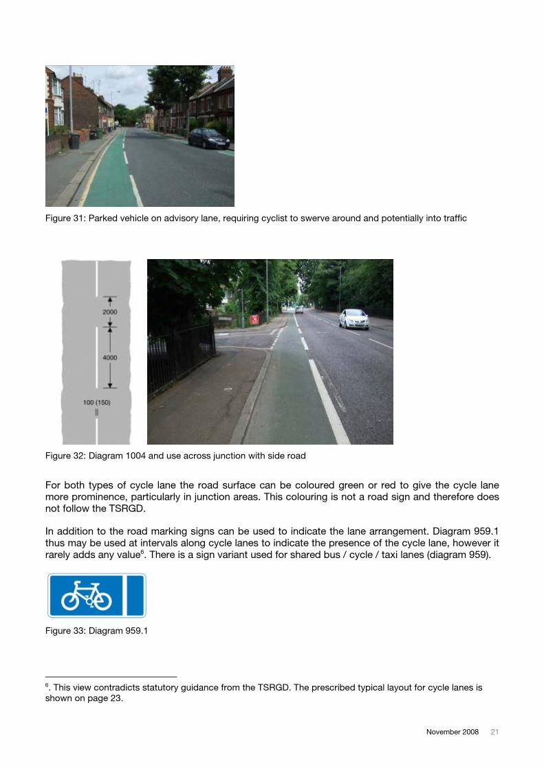
Advisory cycle lanes are lanes where other vehicles may straddle the cycle lane. They are indicated
by a dashed line road marking (diagram 1004). In practice, advisory cycle lanes are regularly
occupied by motor vehicles, and often parked upon. This type of cycle lane should only be used
where cycle lanes cross junction areas (and thus other vehicles may need to cross the cycle lane).
Advisory cycle lanes do not require a Traffic Regulation Order to be set up.
November 2008 21
Figure 31: Parked vehicle on advisory lane, requiring cyclist to swerve around and potentially into traffic
Figure 32: Diagram 1004 and use across junction with side road
For both types of cycle lane the road surface can be coloured green or red to give the cycle lane
more prominence, particularly in junction areas. This colouring is not a road sign and therefore does
not follow the TSRGD.
In addition to the road marking signs can be used to indicate the lane arrangement. Diagram 959.1
thus may be used at intervals along cycle lanes to indicate the presence of the cycle lane, however it
rarely adds any value6. There is a sign variant used for shared bus / cycle / taxi lanes (diagram 959).
Figure 33: Diagram 959.1
6. This view contradicts statutory guidance from the TSRGD. The prescribed typical layout for cycle lanes is
shown on page 23.
22 Signing guidance
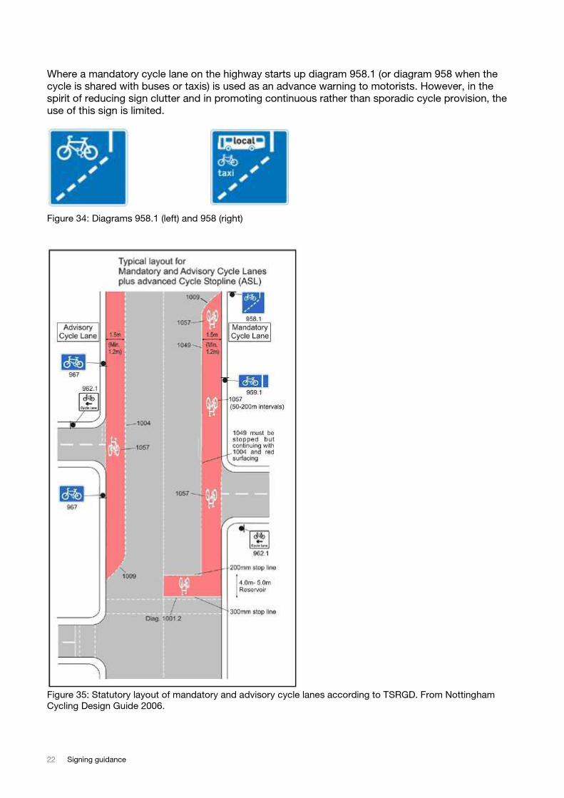
Where a mandatory cycle lane on the highway starts up diagram 958.1 (or diagram 958 when the
cycle is shared with buses or taxis) is used as an advance warning to motorists. However, in the
spirit of reducing sign clutter and in promoting continuous rather than sporadic cycle provision, the
use of this sign is limited.
Figure 34: Diagrams 958.1 (left) and 958 (right)
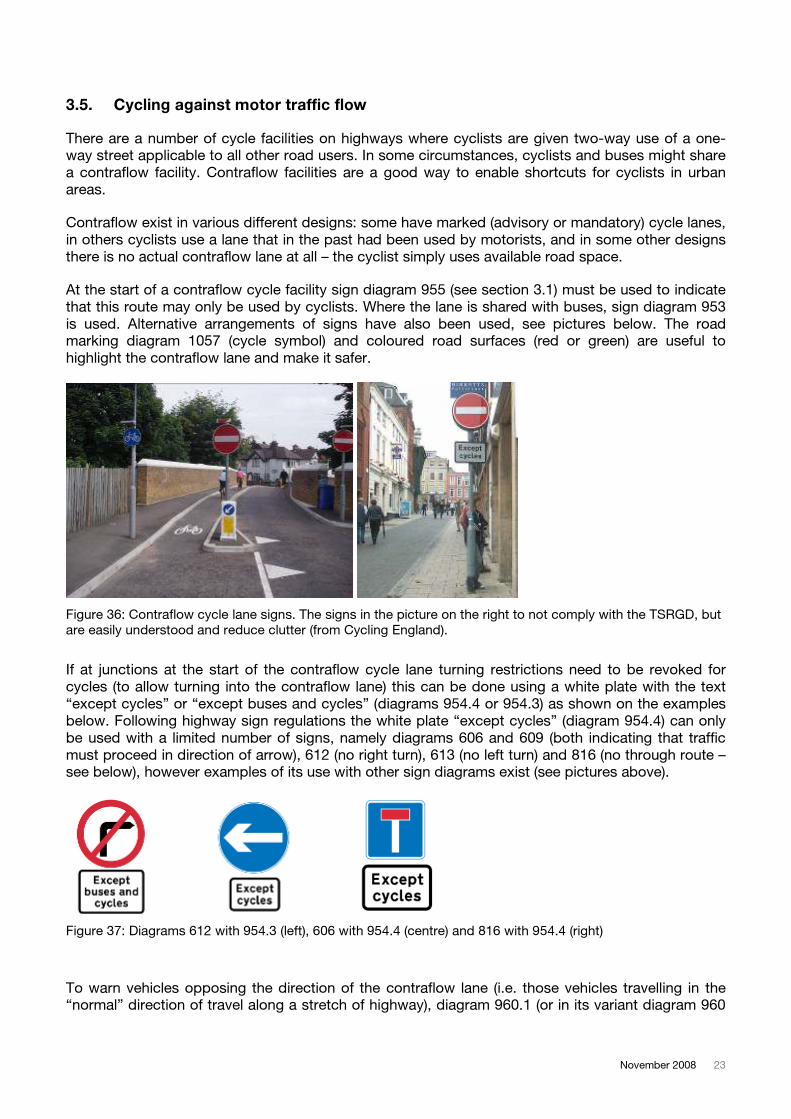
Figure 35: Statutory layout of mandatory and advisory cycle lanes according to TSRGD. From Nottingham
Cycling Design Guide 2006.
November 2008 23
3.5. Cycling against motor traffic flow
There are a number of cycle facilities on highways where cyclists are given two-way use of a one-
way street applicable to all other road users. In some circumstances, cyclists and buses might share
a contraflow facility. Contraflow facilities are a good way to enable shortcuts for cyclists in urban
areas.
Contraflow exist in various different designs: some have marked (advisory or mandatory) cycle lanes,
in others cyclists use a lane that in the past had been used by motorists, and in some other designs
there is no actual contraflow lane at all – the cyclist simply uses available road space.
At the start of a contraflow cycle facility sign diagram 955 (see section 3.1) must be used to indicate
that this route may only be used by cyclists. Where the lane is shared with buses, sign diagram 953
is used. Alternative arrangements of signs have also been used, see pictures below. The road
marking diagram 1057 (cycle symbol) and coloured road surfaces (red or green) are useful to
highlight the contraflow lane and make it safer.
Figure 36: Contraflow cycle lane signs. The signs in the picture on the right to not comply with the TSRGD, but
are easily understood and reduce clutter (from Cycling England).
If at junctions at the start of the contraflow cycle lane turning restrictions need to be revoked for
cycles (to allow turning into the contraflow lane) this can be done using a white plate with the text
“except cycles” or “except buses and cycles” (diagrams 954.4 or 954.3) as shown on the examples
below. Following highway sign regulations the white plate “except cycles” (diagram 954.4) can only
be used with a limited number of signs, namely diagrams 606 and 609 (both indicating that traffic
must proceed in direction of arrow), 612 (no right turn), 613 (no left turn) and 816 (no through route –
see below), however examples of its use with other sign diagrams exist (see pictures above).
Figure 37: Diagrams 612 with 954.3 (left), 606 with 954.4 (centre) and 816 with 954.4 (right)
To warn vehicles opposing the direction of the contraflow lane (i.e. those vehicles travelling in the
“normal” direction of travel along a stretch of highway), diagram 960.1 (or in its variant diagram 960
24 Signing guidance
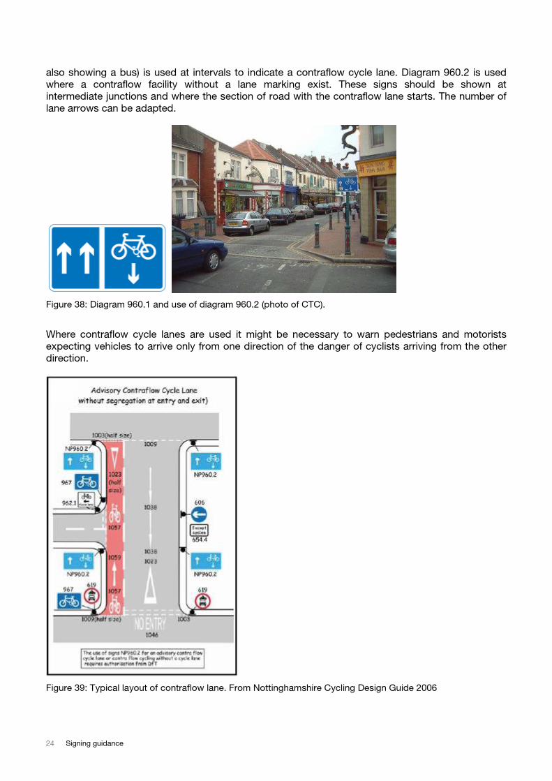
also showing a bus) is used at intervals to indicate a contraflow cycle lane. Diagram 960.2 is used
where a contraflow facility without a lane marking exist. These signs should be shown at
intermediate junctions and where the section of road with the contraflow lane starts. The number of
lane arrows can be adapted.
Figure 38: Diagram 960.1 and use of diagram 960.2 (photo of CTC).
Where contraflow cycle lanes are used it might be necessary to warn pedestrians and motorists
expecting vehicles to arrive only from one direction of the danger of cyclists arriving from the other
direction.
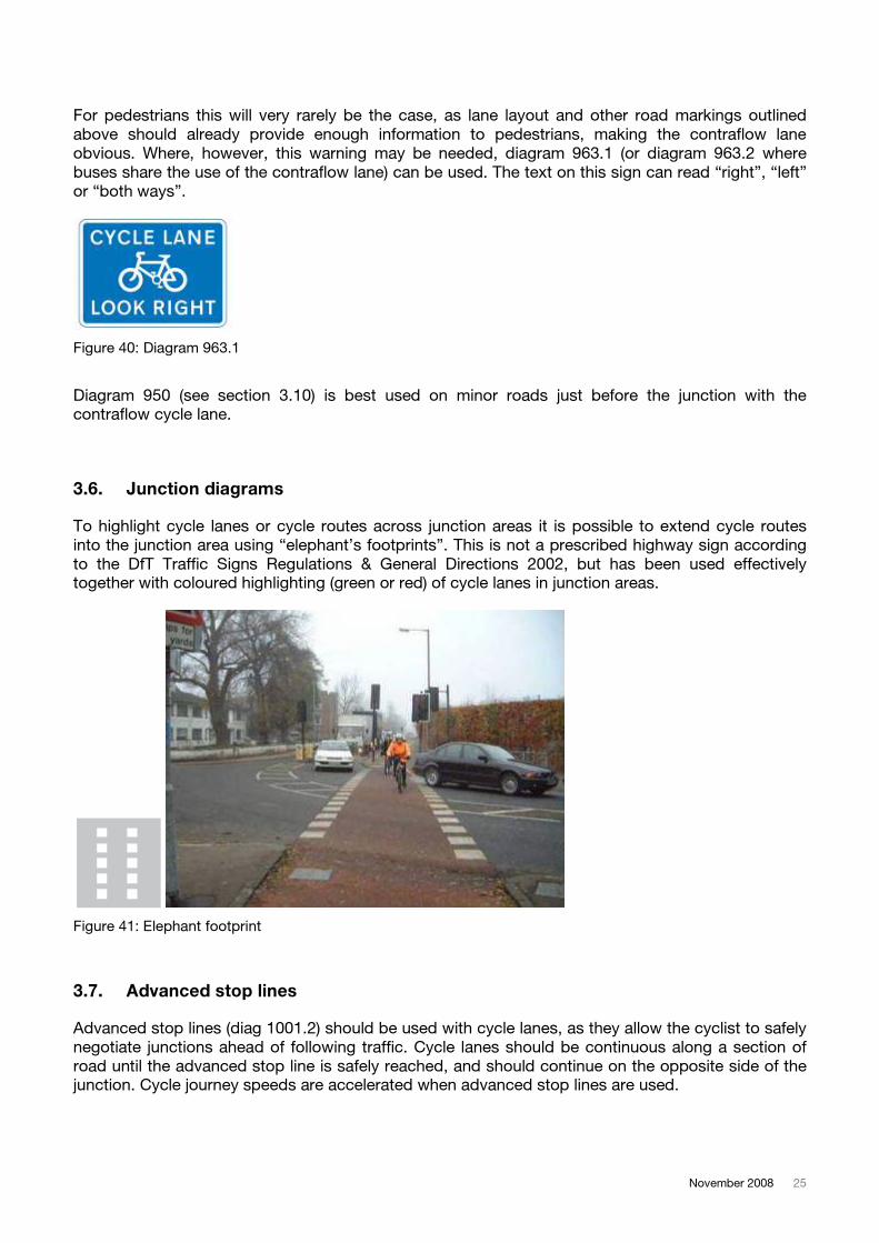
Figure 39: Typical layout of contraflow lane. From Nottinghamshire Cycling Design Guide 2006
November 2008 25
For pedestrians this will very rarely be the case, as lane layout and other road markings outlined
above should already provide enough information to pedestrians, making the contraflow lane
obvious. Where, however, this warning may be needed, diagram 963.1 (or diagram 963.2 where
buses share the use of the contraflow lane) can be used. The text on this sign can read “right”, “left”
or “both ways”.
Figure 40: Diagram 963.1
Diagram 950 (see section 3.10) is best used on minor roads just before the junction with the
contraflow cycle lane.
3.6. Junction diagrams
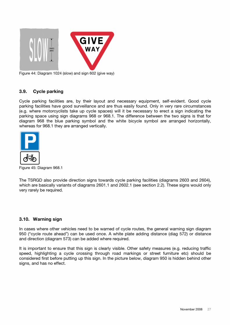
To highlight cycle lanes or cycle routes across junction areas it is possible to extend cycle routes
into the junction area using “elephant’s footprints”. This is not a prescribed highway sign according
to the DfT Traffic Signs Regulations & General Directions 2002, but has been used effectively
together with coloured highlighting (green or red) of cycle lanes in junction areas.
Figure 41: Elephant footprint
3.7. Advanced stop lines
Advanced stop lines (diag 1001.2) should be used with cycle lanes, as they allow the cyclist to safely
negotiate junctions ahead of following traffic. Cycle lanes should be continuous along a section of
road until the advanced stop line is safely reached, and should continue on the opposite side of the
junction. Cycle journey speeds are accelerated when advanced stop lines are used.
26 Signing guidance
Safety at junctions is improved when using advanced stop lines, as cyclists are clear of traffic,
however in good view of motorists.
Advanced stop lines without a feeder lane are not effective, as cyclists struggle getting past other
traffic to reach it safely. Feeder lane design needs to be considered carefully, especially where
cyclists are required to turn right and therefore need to move away from the left side of the
carriageway.
Figure 42: Diagram 1001.2 and example
3.8. Give way
The standard “give way” marking on cycle routes should be a double broken line (diagram 1003) on
the riding surface. Only in few situations will the triangle marking (diagram 1023) be necessary, or
even the vertical red / white give way sign (diagram 602).
Where stopping is not required, the word “slow” (diagram 1024) can be used.
Figure 43: Diagram 1003 (give way line) and diagram 1023 (give way marking)
November 2008 27
Figure 44: Diagram 1024 (slow) and sign 602 (give way)
3.9. Cycle parking
Cycle parking facilities are, by their layout and necessary equipment, self-evident. Good cycle
parking facilities have good surveillance and are thus easily found. Only in very rare circumstances
(e.g. where motorcyclists take up cycle spaces) will it be necessary to erect a sign indicating the
parking space using sign diagrams 968 or 968.1. The difference between the two signs is that for
diagram 968 the blue parking symbol and the white bicycle symbol are arranged horizontally,
whereas for 968.1 they are arranged vertically.
Figure 45: Diagram 968.1
The TSRGD also provide direction signs towards cycle parking facilities (diagrams 2603 and 2604),
which are basically variants of diagrams 2601.1 and 2602.1 (see section 2.2). These signs would only
very rarely be required.
3.10. Warning sign
In cases where other vehicles need to be warned of cycle routes, the general warning sign diagram
950 (“cycle route ahead”) can be used once. A white plate adding distance (diag 572) or distance
and direction (diagram 573) can be added where required.
It is important to ensure that this sign is clearly visible. Other safety measures (e.g. reducing traffic
speed, highlighting a cycle crossing through road markings or street furniture etc) should be
considered first before putting up this sign. In the picture below, diagram 950 is hidden behind other
signs, and has no effect.
28 Signing guidance
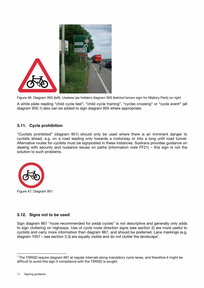
Figure 46: Diagram 950 (left). Useless (as hidden) diagram 950 (behind brown sign for Mallory Park) on right
A white plate reading “child cycle test”, “child cycle training”, “cycles crossing” or “cycle event” (all
diagram 950.1) also can be added to sign diagram 950 where appropriate.
3.11. Cycle prohibition
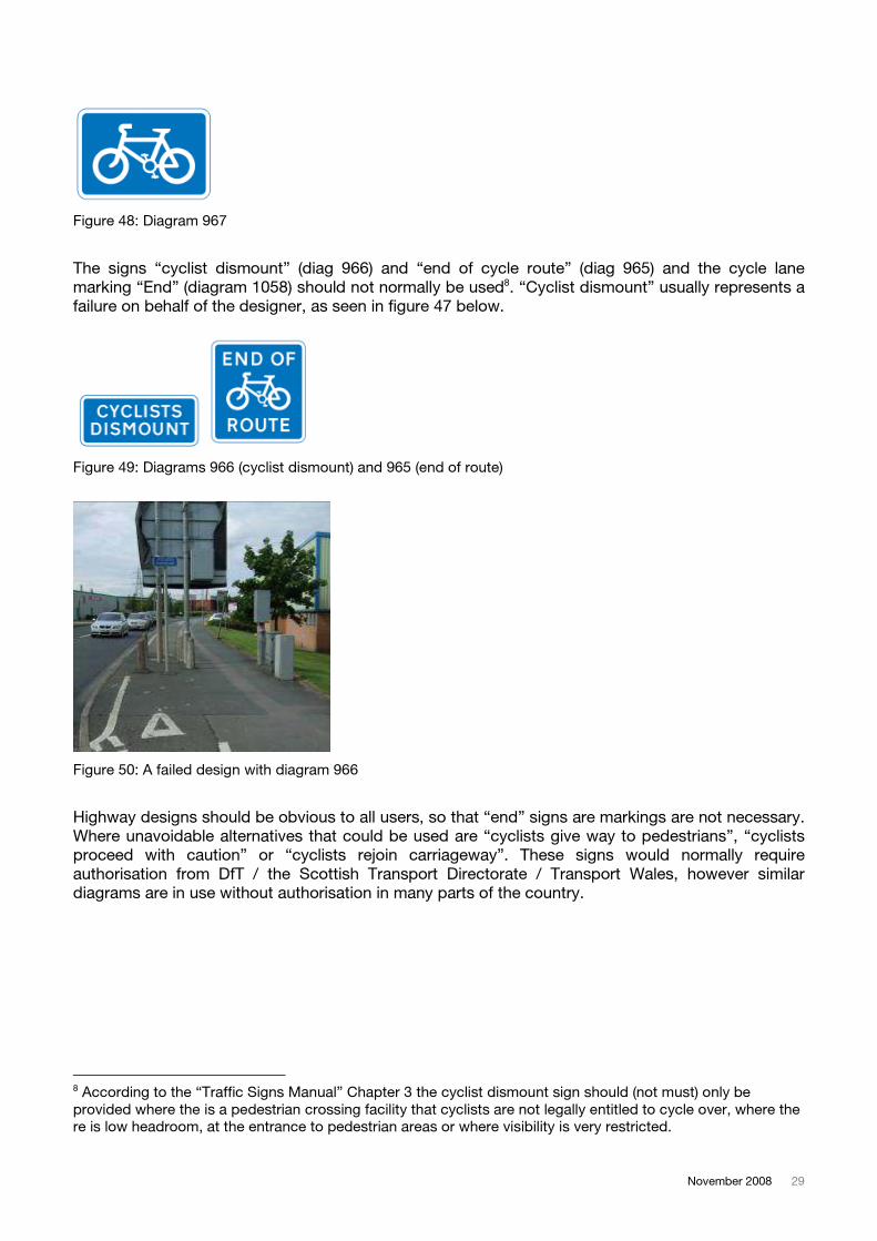
“Cyclists prohibited” (diagram 951) should only be used where there is an imminent danger to
cyclists ahead, e.g. on a road leading only towards a motorway or into a long unlit road tunnel.
Alternative routes for cyclists must be signposted in these instances. Sustrans provides guidance on
dealing with security and nuisance issues on paths (information note FF21) – this sign is not the
solution to such problems.
Figure 47: Diagram 951
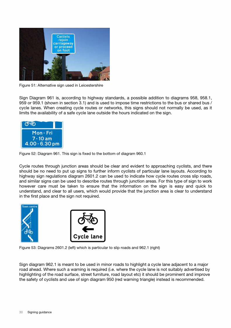
3.12. Signs not to be used
Sign diagram 967 “route recommended for pedal cycles” is not descriptive and generally only adds
to sign cluttering on highways. Use of cycle route direction signs (see section 2) are more useful to
cyclists and carry more information than diagram 967, and should be preferred. Lane markings (e.g.
diagram 1057 – see section 3.3) are equally visible and do not clutter the landscape7.
7 The TSRGD require diagram 967 at regular intervals along mandatory cycle lanes, and therefore it might be
difficult to avoid this sign if compliance with the TSRGD is sought.
November 2008 29
Figure 48: Diagram 967
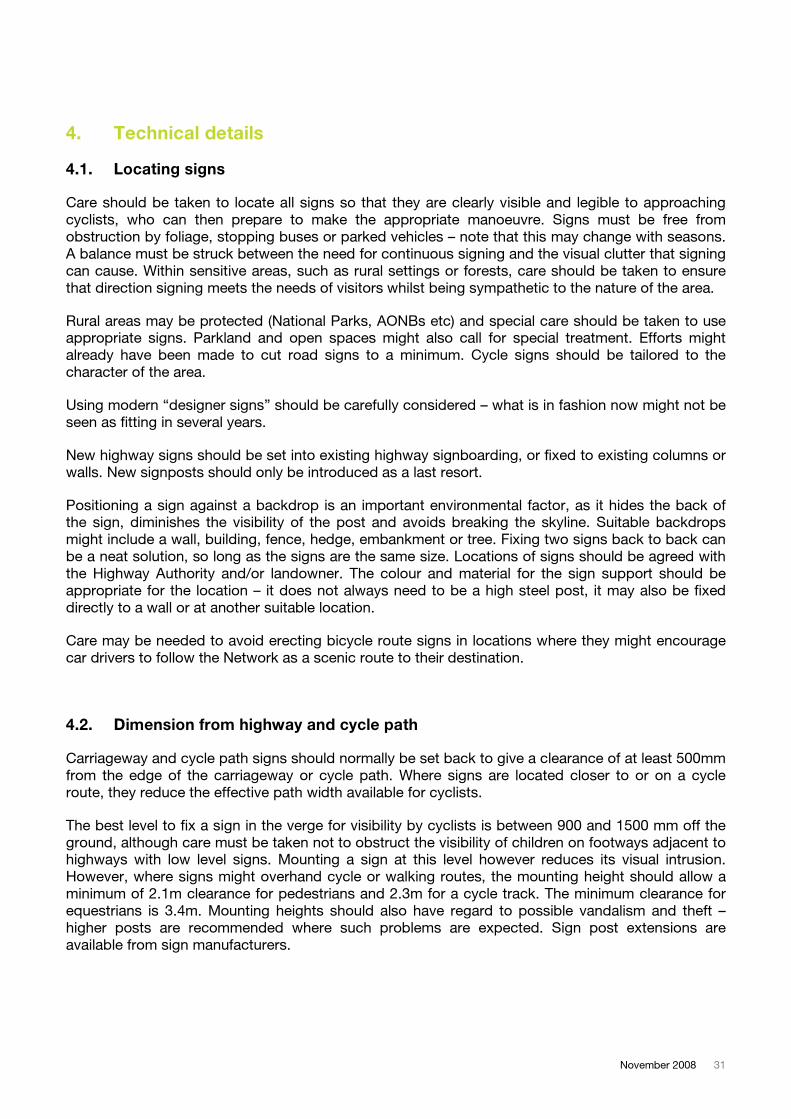
The signs “cyclist dismount” (diag 966) and “end of cycle route” (diag 965) and the cycle lane
marking “End” (diagram 1058) should not normally be used8. “Cyclist dismount” usually represents a
failure on behalf of the designer, as seen in figure 47 below.
8 According to the “Traffic Signs Manual” Chapter 3 the cyclist dismount sign should (not must) only be
provided where the is a pedestrian crossing facility that cyclists are not legally entitled to cycle over, where the
re is low headroom, at the entrance to pedestrian areas or where visibility is very restricted.
Figure 49: Diagrams 966 (cyclist dismount) and 965 (end of route)
Figure 50: A failed design with diagram 966
Highway designs should be obvious to all users, so that “end” signs are markings are not necessary.
Where unavoidable alternatives that could be used are “cyclists give way to pedestrians”, “cyclists
proceed with caution” or “cyclists rejoin carriageway”. These signs would normally require
authorisation from DfT / the Scottish Transport Directorate / Transport Wales, however similar
diagrams are in use without authorisation in many parts of the country.
30 Signing guidance
Figure 51: Alternative sign used in Leicestershire
Sign Diagram 961 is, according to highway standards, a possible addition to diagrams 958, 958.1,
959 or 959.1 (shown in section 3.1) and is used to impose time restrictions to the bus or shared bus /
cycle lanes. When creating cycle routes or networks, this signs should not normally be used, as it
limits the availability of a safe cycle lane outside the hours indicated on the sign.
Figure 52: Diagram 961. This sign is fixed to the bottom of diagram 960.1
Cycle routes through junction areas should be clear and evident to approaching cyclists, and there
should be no need to put up signs to further inform cyclists of particular lane layouts. According to
highway sign regulations diagram 2601.2 can be used to indicate how cycle routes cross slip roads,
and similar signs can be used to describe routes through junction areas. For this type of sign to work
however care must be taken to ensure that the information on the sign is easy and quick to
understand, and clear to all users, which would provide that the junction area is clear to understand
in the first place and the sign not required.
Figure 53: Diagrams 2601.2 (left) which is particular to slip roads and 962.1 (right)
Sign diagram 962.1 is meant to be used in minor roads to highlight a cycle lane adjacent to a major
road ahead. Where such a warning is required (i.e. where the cycle lane is not suitably advertised by
highlighting of the road surface, street furniture, road layout etc) it should be prominent and improve
the safety of cyclists and use of sign diagram 950 (red warning triangle) instead is recommended.
November 2008 31
4. Technical details
4.1. Locating signs
Care should be taken to locate all signs so that they are clearly visible and legible to approaching
cyclists, who can then prepare to make the appropriate manoeuvre. Signs must be free from
obstruction by foliage, stopping buses or parked vehicles – note that this may change with seasons.
A balance must be struck between the need for continuous signing and the visual clutter that signing
can cause. Within sensitive areas, such as rural settings or forests, care should be taken to ensure
that direction signing meets the needs of visitors whilst being sympathetic to the nature of the area.
Rural areas may be protected (National Parks, AONBs etc) and special care should be taken to use
appropriate signs. Parkland and open spaces might also call for special treatment. Efforts might
already have been made to cut road signs to a minimum. Cycle signs should be tailored to the
character of the area.
Using modern “designer signs” should be carefully considered – what is in fashion now might not be
seen as fitting in several years.
New highway signs should be set into existing highway signboarding, or fixed to existing columns or
walls. New signposts should only be introduced as a last resort.
Positioning a sign against a backdrop is an important environmental factor, as it hides the back of
the sign, diminishes the visibility of the post and avoids breaking the skyline. Suitable backdrops
might include a wall, building, fence, hedge, embankment or tree. Fixing two signs back to back can
be a neat solution, so long as the signs are the same size. Locations of signs should be agreed with
the Highway Authority and/or landowner. The colour and material for the sign support should be
appropriate for the location – it does not always need to be a high steel post, it may also be fixed
directly to a wall or at another suitable location.
Care may be needed to avoid erecting bicycle route signs in locations where they might encourage
car drivers to follow the Network as a scenic route to their destination.
4.2. Dimension from highway and cycle path
Carriageway and cycle path signs should normally be set back to give a clearance of at least 500mm
from the edge of the carriageway or cycle path. Where signs are located closer to or on a cycle
route, they reduce the effective path width available for cyclists.
The best level to fix a sign in the verge for visibility by cyclists is between 900 and 1500 mm off the
ground, although care must be taken not to obstruct the visibility of children on footways adjacent to
highways with low level signs. Mounting a sign at this level however reduces its visual intrusion.
However, where signs might overhand cycle or walking routes, the mounting height should allow a
minimum of 2.1m clearance for pedestrians and 2.3m for a cycle track. The minimum clearance for
equestrians is 3.4m. Mounting heights should also have regard to possible vandalism and theft –
higher posts are recommended where such problems are expected. Sign post extensions are
available from sign manufacturers.

32 Signing guidance
4.3. Putting up signs
Only the Highway Authority has powers to erect signs and road markings on the public highway, which it can do directly or through an approved contractor. Any organisation with suitable capabilities may apply to become an approved contractor for erecting signs. On cycle routes away from highways, signs may be erected by any party with the permission of the landowner.
4.4. Text and sign size
The size of signs is usually dependent on the text that is shown, and therefore dependant on the text
size that is used. The normal way to determine the size of text is using the height of the letter ‘x’
(called the “x – height”). Standard signs usually have a standard size or size options.
4.4.1. Signs with text
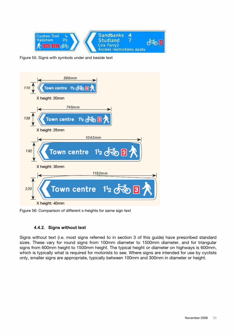
There is no absolute ‘right’ size. Cycle route signs have a smaller ‘x – height’ than, for example, motorway signs which have to be readable at high speed and distance. For bicycle and pedestrian signs in public highways in urban areas, the ‘x – height’ is usually 35mm. For signs incorporated onto other highway signs that are mounted at height or on busy roads, the ‘x –height’ can be increased to 40mm so that people can see it more easily. On traffic free cycle routes, in sensitive areas of natural beauty, on rural highways or where there are no other signs around, the ‘x – height’ should be 25mm. On rare occasions smaller text sizes have been used but this should only be done for information that is in addition to the main destination displayed on a sign (e.g. where there are two route options to the same destinations, and additional information is given to describe the different options or see example below).
Figure 54: 25mm x-height in rural setting (left). Smaller text to minimise sign size (right)
Once the “x – height” has been determined sign manufacturers can produce standardised sign boards using prescribed margins and line spacing. This information is available from sign manufacturers on request or is given in “The National Cycle Network: Guidelines and Practical Details” (see references).
It should be noted that symbols on signs can appear next to or under the text displayed on a sign (see examples below). The choice is up to the person designing the sign. For fingerpost style signs fixed at one end only it is usually best to have a shorter sign, while for centrally mounted (or face mounted) signs longer signs do not present such a problem.
November 2008 33
Figure 55: Signs with symbols under and beside text
Figure 56: Comparison of different x-heights for same sign text
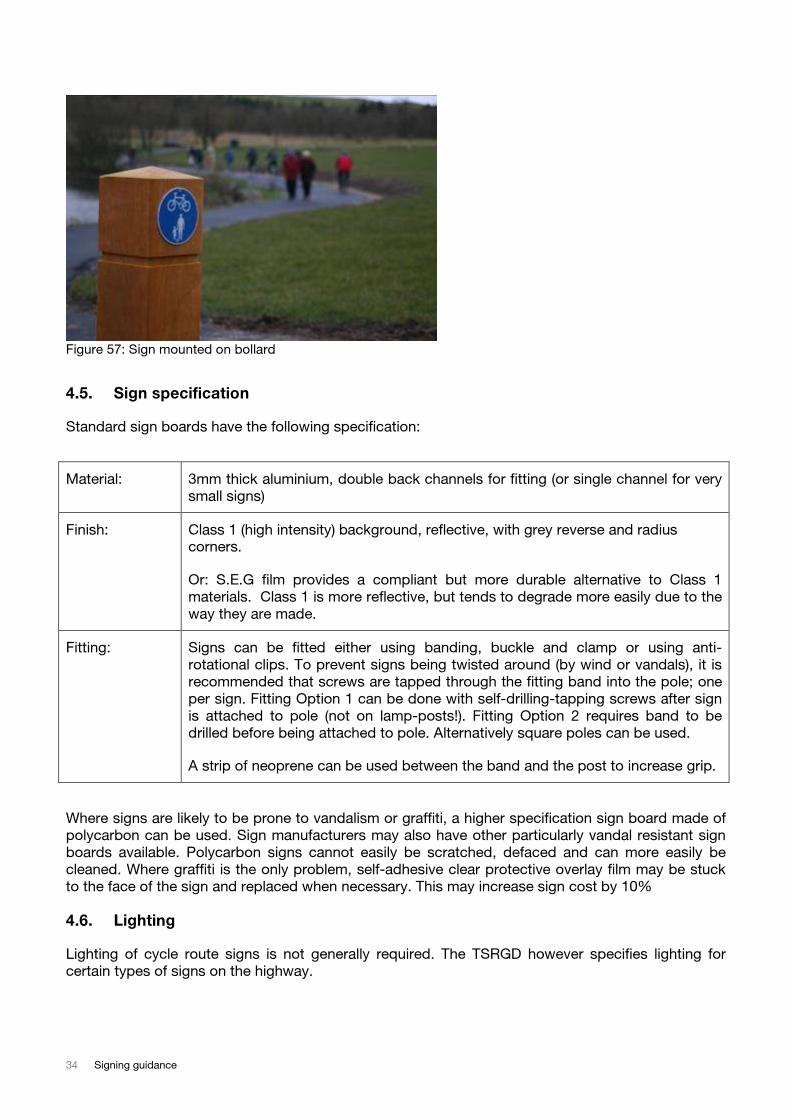
4.4.2. Signs without text
Signs without text (i.e. most signs referred to in section 3 of this guide) have prescribed standard
sizes. These vary for round signs from 100mm diameter to 1500mm diameter, and for triangular
signs from 600mm height to 1500mm height. The typical height or diameter on highways is 600mm,
which is typically what is required for motorists to see. Where signs are intended for use by cyclists
only, smaller signs are appropriate, typically between 100mm and 300mm in diameter or height.
34 Signing guidance
Figure 57: Sign mounted on bollard
4.5. Sign specification
Standard sign boards have the following specification:
Material: 3mm thick aluminium, double back channels for fitting (or single channel for very
small signs)
Finish: Class 1 (high intensity) background, reflective, with grey reverse and radius
corners.
Or: S.E.G film provides a compliant but more durable alternative to Class 1
materials. Class 1 is more reflective, but tends to degrade more easily due to the
way they are made.
Fitting: Signs can be fitted either using banding, buckle and clamp or using anti-
rotational clips. To prevent signs being twisted around (by wind or vandals), it is
recommended that screws are tapped through the fitting band into the pole; one
per sign. Fitting Option 1 can be done with self-drilling-tapping screws after sign
is attached to pole (not on lamp-posts!). Fitting Option 2 requires band to be
drilled before being attached to pole. Alternatively square poles can be used.
A strip of neoprene can be used between the band and the post to increase grip.
Where signs are likely to be prone to vandalism or graffiti, a higher specification sign board made of
polycarbon can be used. Sign manufacturers may also have other particularly vandal resistant sign
boards available. Polycarbon signs cannot easily be scratched, defaced and can more easily be
cleaned. Where graffiti is the only problem, self-adhesive clear protective overlay film may be stuck
to the face of the sign and replaced when necessary. This may increase sign cost by 10%
4.6. Lighting
Lighting of cycle route signs is not generally required. The TSRGD however specifies lighting for
certain types of signs on the highway.
November 2008 35
4.7. Sign posts
Standard highway signposts have the following specification:
Poles 3.3 - 3.75 metre length, 76mm diameter (or 80mm square), galvanised steel
poles, complete with plastic caps (unless manufactured with welded steel cap)
This length of pole is used to deter vandalism by making the signs difficult to
reach. However, shorter poles can be used where necessary – for example, in
rural areas where high poles would be unnecessary or visually obtrusive. Use
square post only if the sign direction(s) can be indicated accurately. Sign post
extensions can be manufactured if necessary.
Installation Poles set in 0.5m³ C20 concrete, set 0.7m deep in ground. A baseplate should be
fitted to prevent poles being lifted out. A horizontal bar diagonally through the
pole cast into the concrete prevents the pole being rotated. Approximately one
third of the pole should be buried in the concrete.
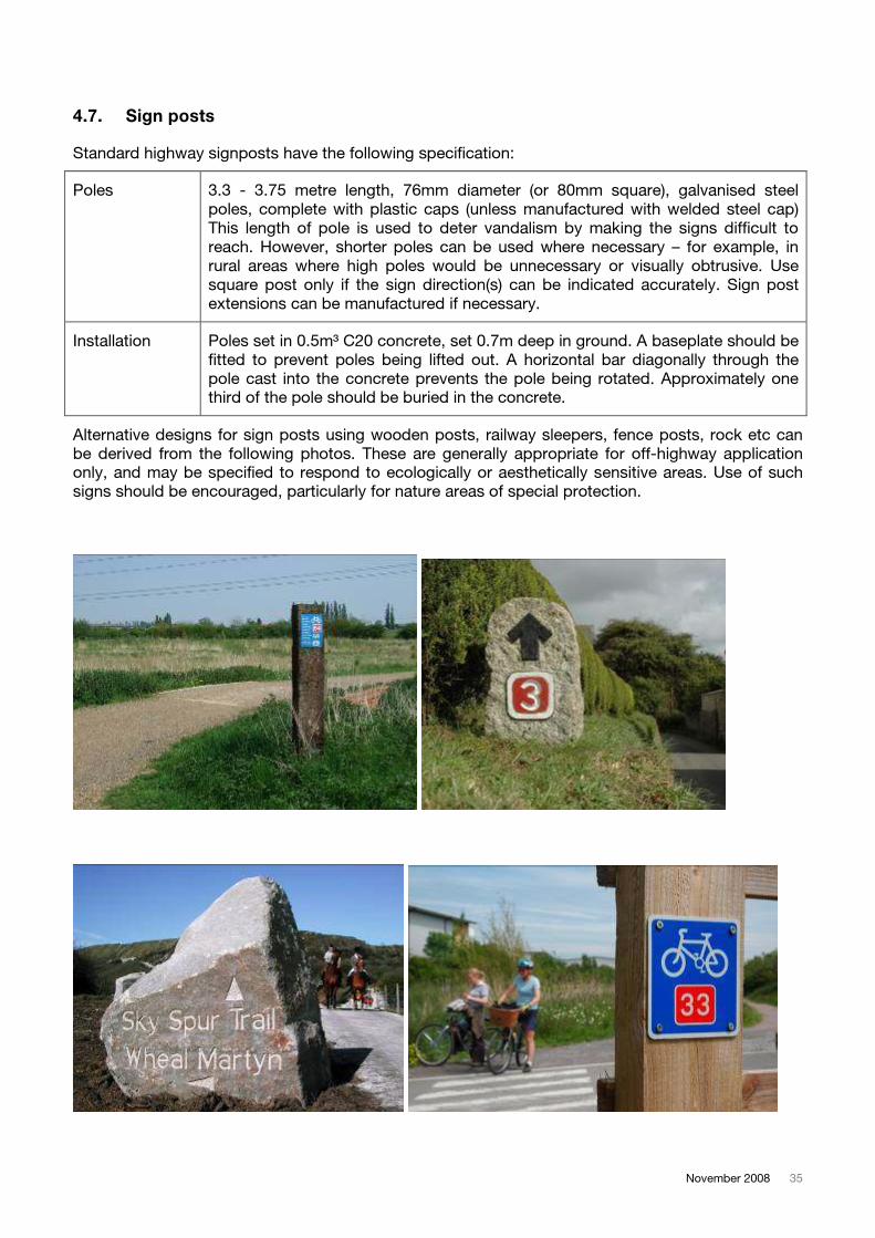
Alternative designs for sign posts using wooden posts, railway sleepers, fence posts, rock etc can
be derived from the following photos. These are generally appropriate for off-highway application
only, and may be specified to respond to ecologically or aesthetically sensitive areas. Use of such
signs should be encouraged, particularly for nature areas of special protection.
36 Signing guidance
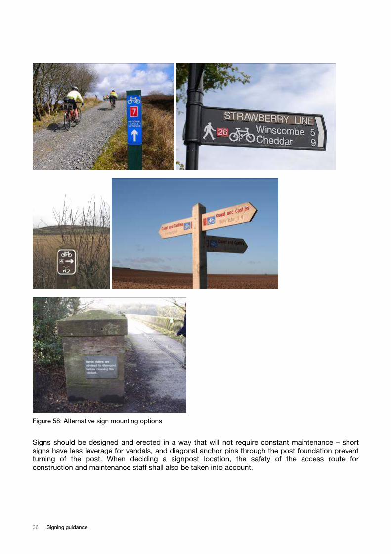
Figure 58: Alternative sign mounting options
Signs should be designed and erected in a way that will not require constant maintenance – short
signs have less leverage for vandals, and diagonal anchor pins through the post foundation prevent
turning of the post. When deciding a signpost location, the safety of the access route for
construction and maintenance staff shall also be taken into account.
November 2008 37
4.8. Road markings
The following is extracted from the DfT Traffic Signs Manual, Chapter 5, sections 23.2 – 23.8.
“Road markings are applied using thermoplastic, cold plastic, preformed material or paint. They may
be laid as permanent markings or as temporary markings.
Thermoplastic material is applied hot and sets on laying. It may be applied by a hand or mechanical
applicator. It has good durability and is suitable for use on all roads. Mechanical application is most
suitable for busy roads, as it can be done fast.
Cold plastics are supplied in single or multicomponent forms. The product is laid on the carriageway
and a cohesive film is formed by chemical action.
Preformed thermoplastic road markings are applied by heating the material until it bonds to the road
surface by melting or fusion. They provide a simple way to apply arrows, lettering etc. and to
reinstate short lengths of line without the need for substantial application and support equipment.
Preformed cold plastic material is applied to the road surface using an adhesive.
Preformed tape is produced in sheet or roll form and is either bonded to the road surface or inlaid.
Pressure is applied, but not heat. Preformed markings have good durability, are of uniform thickness
and do not spread in hot weather or under the weight of heavy traffic. They can be difficult to apply
to some surface dressings and block paviors. They are also manufactured in an easily removable
form for use at road works.
Paint is best restricted to roads where the markings are not subject to heavy traffic wear. It is
particularly suitable for edge lining as, being thinner than thermoplastic material, it will not interfere
with drainage. The ease and safety in handling paint compared to thermoplastic material, its
suitability for laying with motorised equipment and the material's low initial cost, makes paint an
attractive economic proposition for such applications.”
Where road markings are used, reflectorisation should be used for cycle routes lane markings on
highways to give extra protection at night. For routes away from highways reflectorisation is not
normally required. Texture can be applied to lane markings, however where cyclists need to cross
lanes texture is uncomfortable to the rider and should be avoided. Highway drainage may require
lane markings to have texture to allow the flow of water of the carriageway.
38 Signing guidance
5. Additional Information
5.1. Temporary Diversion Signs
Temporary diversions of cycle routes may be required while road works are being carried out. For
each worksite contractors are required to submit a signing schedule to the overseeing highways
authority, according to Chapter 8 of the DfT Traffic Signs Manual (2006). Where cycle routes are
affected by street works, these should be diverted on a safe route around the construction works.
Principles for diversion route quality should be the same as those for normal other cycle routes (see
The National Cycle Network: Guidelines and Practical Details).
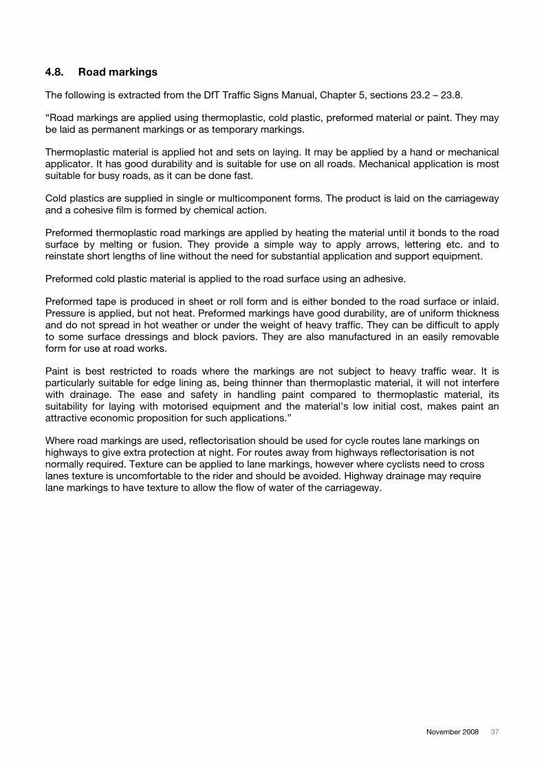
Figure 59: Cycle route diversion on yellow background
Signposting along diversion routes should follow the principles for signposting highway diversion, i.e.
using yellow background directional signs in the same style as normal (blue background) directional
signs would be. ‘X – heights’ should be the same as normal cycle route signs.
At the start of the diversion, the alternative route should be clearly displayed using a sign similar in
style to diagram 2601.2 (see section 3.6). At the end of the diversion a “Diversion ends” signs should
be displayed.
There is a variant to the “cyclist dismount” sign that appears in highway signing legislation intended
for use temporarily during highway works (diag 7018.1). This sign should be avoided and contractors
should be encouraged to provide temporary cycle facilities adjacent to their work site.
Figure 60: Diagram 7018.1
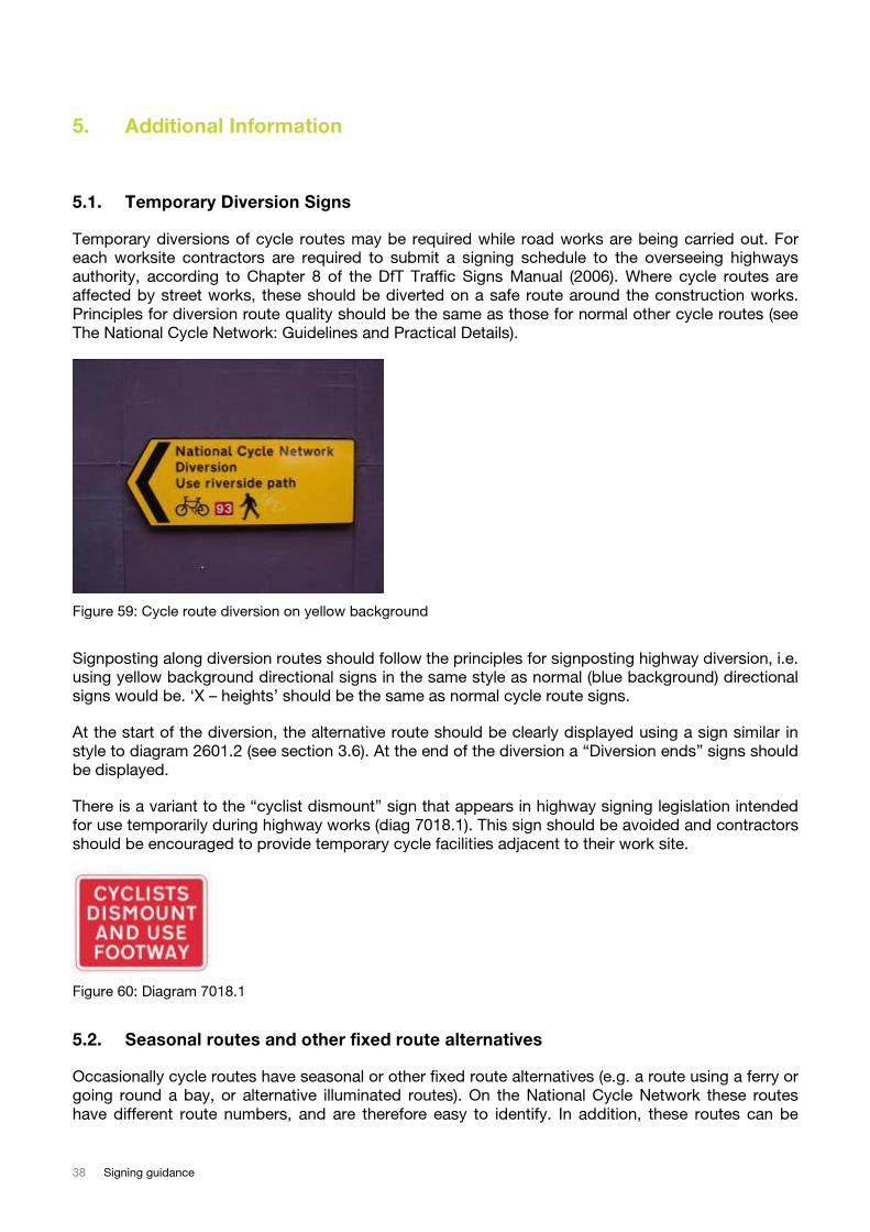
5.2. Seasonal routes and other fixed route alternatives
Occasionally cycle routes have seasonal or other fixed route alternatives (e.g. a route using a ferry or
going round a bay, or alternative illuminated routes). On the National Cycle Network these routes
have different route numbers, and are therefore easy to identify. In addition, these routes can be
November 2008 39
signposted using the normal range of signs, but using additional commentary shown with the ‘x –
height’ of 20mm. One example is shown below.
Figure 61: Diagram 2062.1
5.3. Cycle events
Cycle events vary in their requirements for signing depending on the type and size of event taking
place. It is recommended for event organisers to make individual arrangements with local highway
authorities.
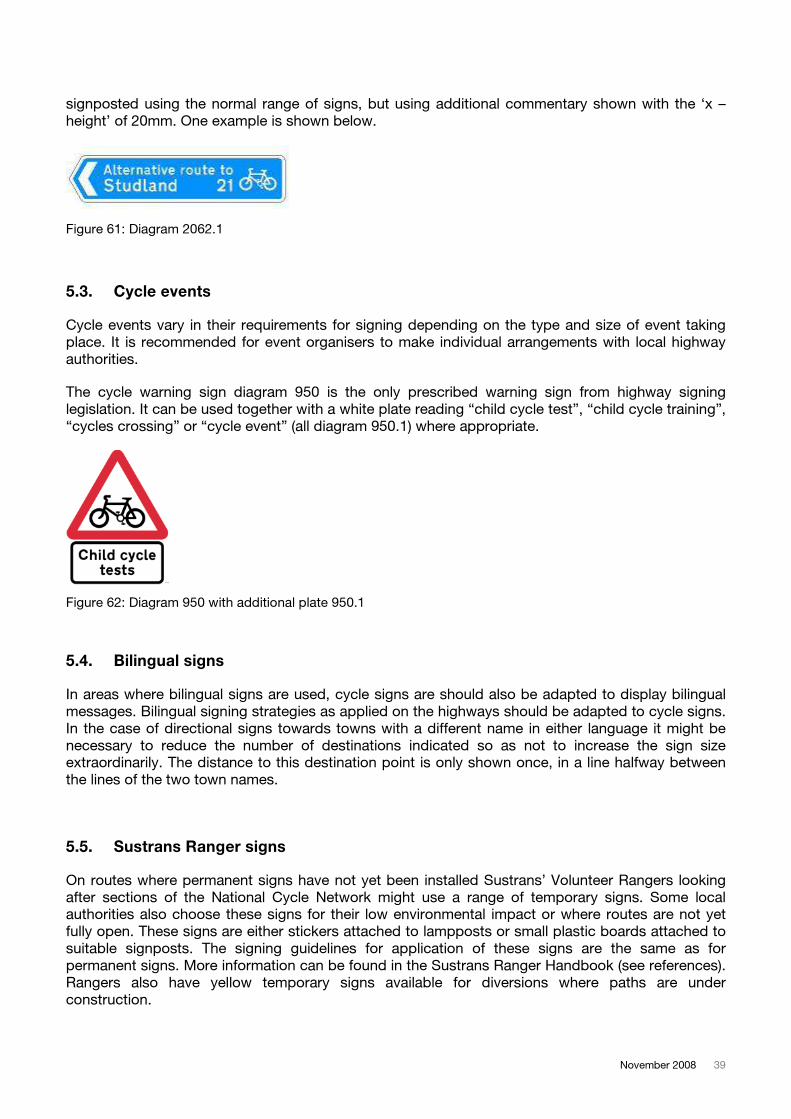
The cycle warning sign diagram 950 is the only prescribed warning sign from highway signing
legislation. It can be used together with a white plate reading “child cycle test”, “child cycle training”,
“cycles crossing” or “cycle event” (all diagram 950.1) where appropriate.
Figure 62: Diagram 950 with additional plate 950.1
5.4. Bilingual signs
In areas where bilingual signs are used, cycle signs are should also be adapted to display bilingual
messages. Bilingual signing strategies as applied on the highways should be adapted to cycle signs.
In the case of directional signs towards towns with a different name in either language it might be
necessary to reduce the number of destinations indicated so as not to increase the sign size
extraordinarily. The distance to this destination point is only shown once, in a line halfway between
the lines of the two town names.
5.5. Sustrans Ranger signs
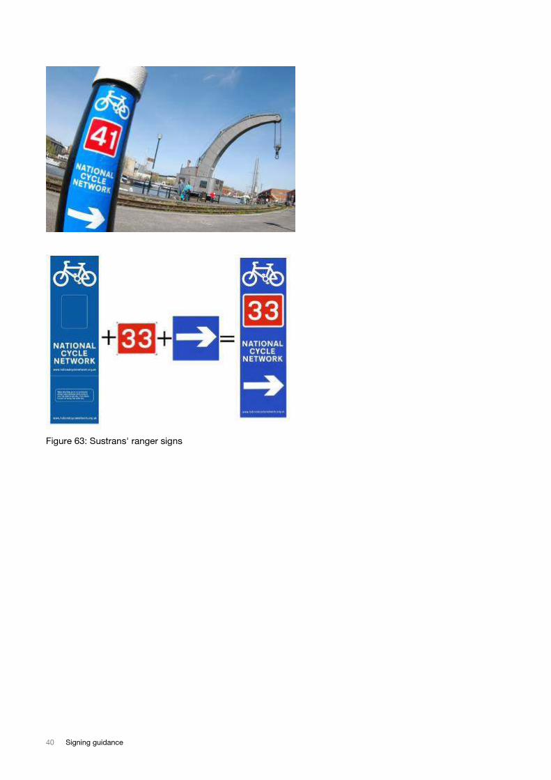
On routes where permanent signs have not yet been installed Sustrans’ Volunteer Rangers looking
after sections of the National Cycle Network might use a range of temporary signs. Some local
authorities also choose these signs for their low environmental impact or where routes are not yet
fully open. These signs are either stickers attached to lampposts or small plastic boards attached to
suitable signposts. The signing guidelines for application of these signs are the same as for
permanent signs. More information can be found in the Sustrans Ranger Handbook (see references).
Rangers also have yellow temporary signs available for diversions where paths are under
construction.
40 Signing guidance
Figure 63: Sustrans' ranger signs
November 2008 41
6. How to plan and order signs
1. Cycle the route in both directions, including all links leading towards the route and links leading away from it. Roads crossing the cycle route or leading towards it probably also
require signs or road markings. Cycling along a route will ensure that signs and markings are
appropriate to the user, and in useful locations. Driving the route could give you the wrong
sense of what is required
2. Identify all critical locations where signs are required
o Dangerous areas
o Priority arrangements
o Junctions / forks
o Permitted user groups, restrictions, prohibitions, instructions
o Confirmation sign locations
3. Decide on required signs
4. Draw up list of destinations that appear on signs - identify unique locations that people can identify on maps.
5. Measure distances between destination points along cycle route so that distances on the signs are accurate for the cyclist
6. Consider additional information – area maps, information boards, plaques, finials, shared use codes and suitable locations.
7. Consider the location and its surroundings
o Consider the type of sign appropriate to surrounding
o Consider size of sign (or x – height of text) that is appropriate
o Sign post / lamp post availability or any other suitable mounting structure (see section 4.7)
8. Develop signing schedule, then extract information into ordering spreadsheet. Ensure that signing is covered in both directions along the route. Specify sign types, sizes, location,
mounting height and fixing method. Ensure that destination signing is consistent, and that
destinations can be reached by using the cycle route.
o A list of available signs with their sign code is enclosed in appendix A.
o An example signing schedule is enclosed in appendix B.
o Blank sample spreadsheets for developing a sign order for different types of signs is included in appendix C.
42 Signing guidance
9. Place order with supplier or contractor. Suppliers and contractors need clear information on sign locations, specifications and identification presented in a well illustrated schedule. This
should assist the contractor with installing the signs correctly, allow cross – checking and
also approval by external bodies as required.
7. Sign surveys
After a route has initially been signed and at intervals later on, it is vital to check that the signs have
been erected as specified and that necessary corrections are made. It is strongly recommend that
the adequacy of the signing be reviewed in both directions. It is recommended that cyclists
unfamiliar with a route are taken along to signing checks to identify gaps in the signing. This
independent assessment by a cyclist may pick up aspects of the signing that should be improved.
The sign survey should then be used to amend signs, replace signs, order new signs and update
records of signs. Cycle routes may change, and surveys will identify whether signing is still up to
date.
Before surveying, it is important to check local records, gather up local knowledge of routes local
cyclists use (which might be different from those currently signed) and gather up sign defect records
(usually held by local councils / highway authorities and sometimes local cycling groups). To avoid
duplicate site visits especially to remote areas, it can also be useful to simply take small tools and a
sample of temporary signs (stickers) along to the survey to fix small problems while the survey is
carried out.
Surveys are only successful if useful and good quality information is collected. Photographic records
need to be of good quality and linked to locations and field notes, sign locations and orientations
need to be recorded accurately, and the surveyor needs to identify locations on maps accurately.
Preparing survey sheets to prompt recording the right information may be useful.
Sustrans has in the past used digital recording methods for surveys of routes, using GPS based
recording equipment that can easily carried on a bicycle. This information can then be linked with
digitally held geographic information, field notes, photographs and map locations to form one
surveying database. If dictaphones are used to record information, this might need to be transcribed
into written records.
Information collected during the survey should consider the following points
o The cyclists’ perspective as they approach the sign / location
o Where the sign is seen from – impacts of x-height/ orientation / mounting
o Is the route on-road or traffic-free
o Will the cyclist be stationary or moving?
o Sign post details – is a new post needed or is it sufficient
o Is an additional confirmation sign needed?
o Vandalism prone areas, and solutions required
o Sign clutter – are the signs appropriate
o Vegetation encroachment – seasonal changes

November 2008 43
o Is road marking more appropriate than a sign?
It is useful to record more information on site rather than less, as this best prevents that the site
needs to be revisited. Photos should be taken from various angles to allow viewing the whole site
from the office. Take photos at different zoom levels, and use bikes or people for scale.
Surveys need adequate time to write up and analyse. Depending on complexity and experience, a
day on site will probably require several days in the office to sort out data and develop conclusions
from the survey. Surveys that are not followed up by an implementation stage of the outcomes may
be useless.
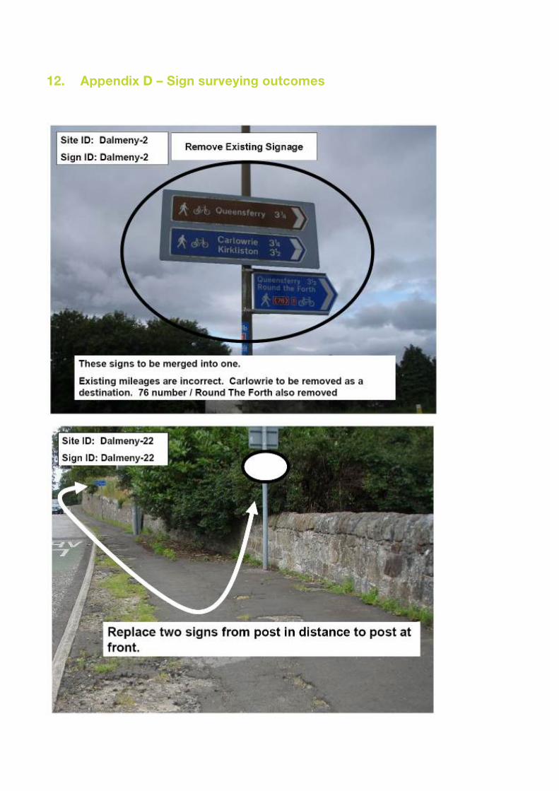
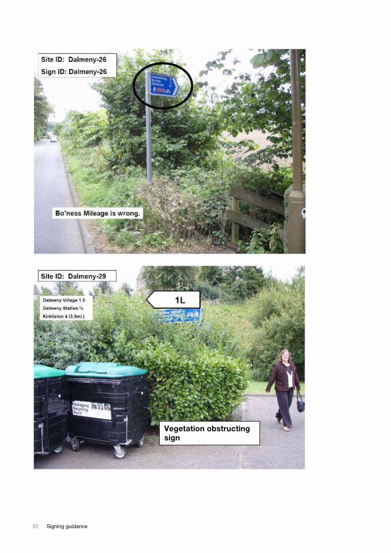
Appendix D contains typical sign surveying outcomes.
44 Signing guidance
8. Appendix A - Overview of signs
Direction Signs
Direction sign
with arrow
Pointing direction
sign
Route
confirmation
As
2601.1
As 2602.1
2601.1 2602.1 2602.2 2105.1 2106.1
Cycle paths and shared use
Cycles route
only
Cycles and
pedestrian
route only
Cycles and
pedestrian
route only
Cycle and
bus route
only
Pedestrian
zone
(cycling not
permitted)
Pedestrian
zone
(cycling
permitted)
955 956 957 953 618.2 618.2
Homezones
Homezone
starts
Homezone
ends
Northern
Ireland only -
Homezone
881 882 544.1
Parking, warning and temporary signs
Cycle
parking
Warning of
cyclists
Warning with
particular note
No cycling Temporary sign
966.1 950 950 with 950.1 951 7018.1
November 2008 45
Signs not to be used
Road markings
Cycle and bus
route only
Mandatory
cycle lane
Advisory
cycle
lane
Cycle route Advanced
stop line
Elephant
footprint
1048.4 1049 1004 1057 1001.2 No number
Cycle Lanes
Cycle lane Start of
cycle lane
Contraflow
cycle lane
Warning of
cyclists for
pedestrians
Cycle
route
across
junction
Warning of
cycle lane for
motorists
959.1 958.1 960.1 963.1 2601.2 962.1
Entry only permitted to cyclists (and buses)
No right turn
except cycles
Left turn only
expect
cycles
No through
road except
cycles
All vehicles prohibited
except cycles pushed
by pedestrians
No motor
vehicles
612 with 954.3 606 with
954.4
616 with
954.4
617 619
Cycle route Cyclists
dismount
End of
route
Time restrictions
for routes
Cycle route
across
junction
Warning of
cycle lane for
motorists
967 966 965 961 2601.2 962.1
46 Signing guidance
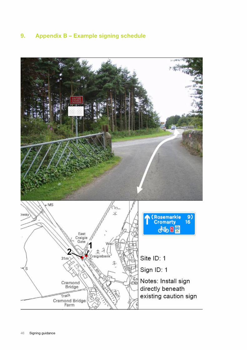
9. Appendix B – Example signing schedule
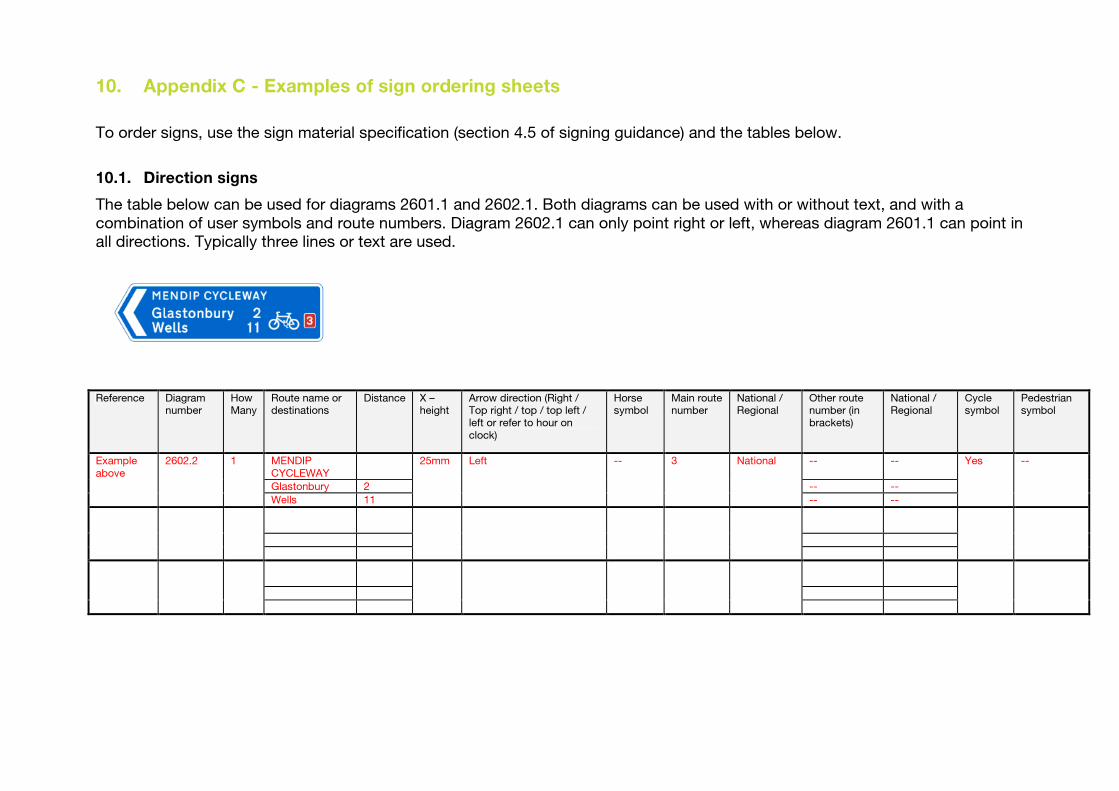
10. Appendix C - Examples of sign ordering sheets
To order signs, use the sign material specification (section 4.5 of signing guidance) and the tables below.
10.1. Direction signs
The table below can be used for diagrams 2601.1 and 2602.1. Both diagrams can be used with or without text, and with a
combination of user symbols and route numbers. Diagram 2602.1 can only point right or left, whereas diagram 2601.1 can point in
all directions. Typically three lines or text are used.
Reference Diagram
number How Many
Route name or destinations
Distance X – height
Arrow direction (Right / Top right / top / top left /
left or refer to hour on
clock)
Horse symbol
Main route number
National / Regional
Other route number (in
brackets)
National / Regional
Cycle symbol
Pedestrian symbol
MENDIP
CYCLEWAY
-- --
Glastonbury 2 -- --
Example
above
2602.2 1
Wells 11
25mm Left -- 3 National
-- --
Yes --
48 Signing guidance
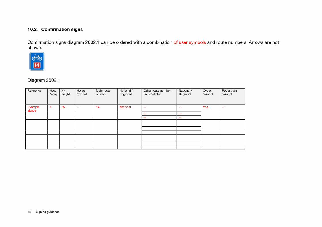
10.2. Confirmation signs
Confirmation signs diagram 2602.1 can be ordered with a combination of user symbols and route numbers. Arrows are not
shown.
Diagram 2602.1
Reference How
Many X - height
Horse symbol
Main route number
National / Regional
Other route number (in brackets)
National / Regional
Cycle symbol
Pedestrian symbol
-- --
-- --
Example above
1 25 -- 14 National
-- --
Yes --
November 2008 49
10.3. Other signs
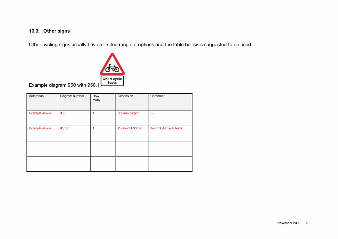
Other cycling signs usually have a limited range of options and the table below is suggested to be used
Example diagram 950 with 950.1
Reference Diagram number How
Many
Dimension Comment
Example above 950 1 300mm height --
Example above 950.1 1 X – height 30mm Text: Child cycle tests
50 Signing guidance
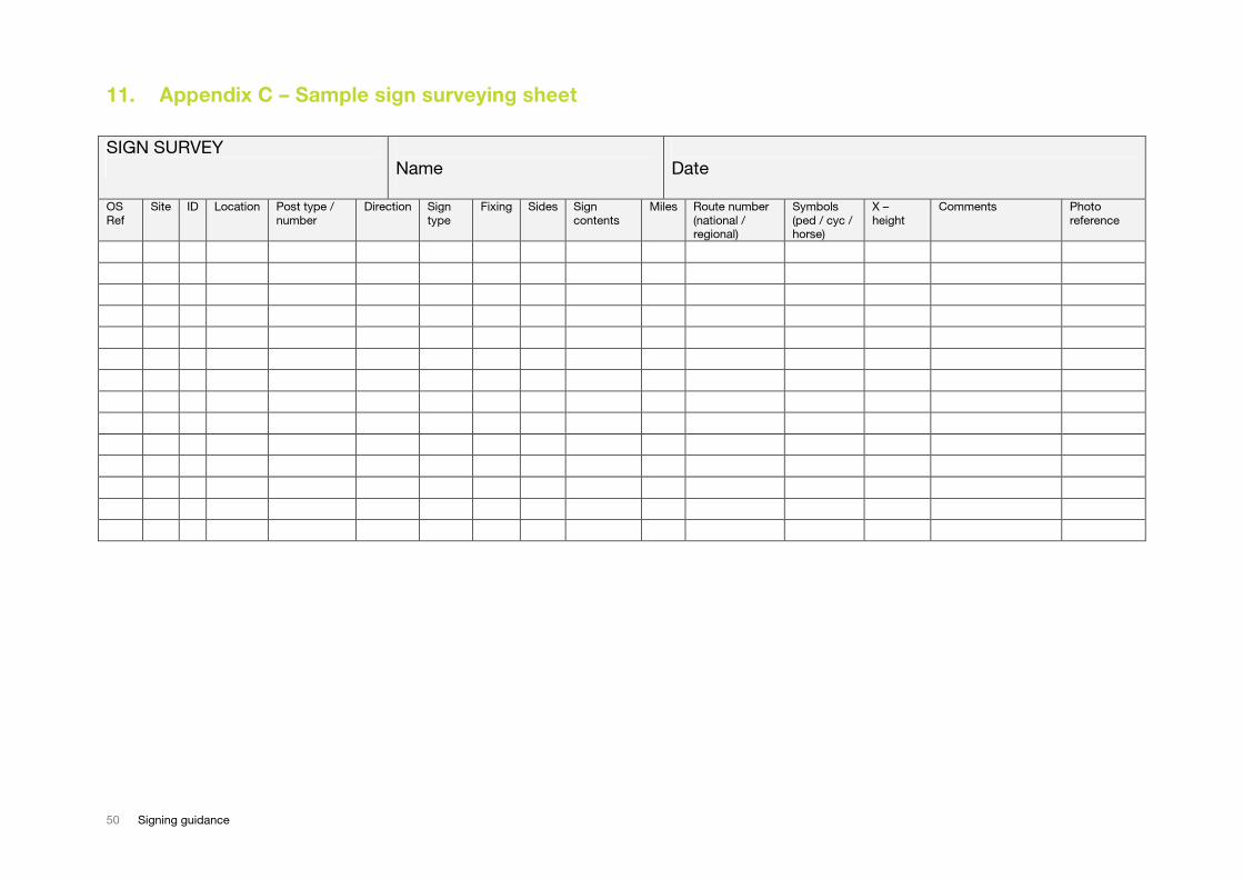
11. Appendix C – Sample sign surveying sheet
SIGN SURVEY
Name
Date
OS
Ref
Site ID Location Post type /
number
Direction Sign
type
Fixing Sides Sign
contents
Miles Route number
(national / regional)
Symbols
(ped / cyc / horse)
X –
height
Comments Photo
reference
12. Appendix D – Sign surveying outcomes
52 Signing guidance
Vegetation obstructing
sign
November 2008 53
13. References
HMSO (2002) Traffic Signs Regulations and General Directions 2002
<http://www.opsi.gov.uk/si/si2002/20023113.htm>
HMSO (2006) Traffic Signs Manual 2006 <http://www.dft.gov.uk/pgr/roads/tss/tsmanual/>
Sustrans and Ove Arup & Partners, 1997, The National Cycle Network: Guidelines and Practical
Details, Issue 2 <http://www.sustrans.org.uk/default.asp?sID=1100529418828&pID=>
Transport for London, 2005, London Cycling Design Standards
http://www.tfl.gov.uk/cycles/company/standards.shtml
Sustrans Ranger Handbook – available from Sustrans <www.sustrans.org.uk> Tel: 0845 113 00 65
Email: [email protected]
Sustrans Sustrans Good Cycling Code Information Note FF15.
<http://www.sustrans.org.uk/webfiles/Info%20sheets/ff15.pdf>