Embed Size (px)
Citation preview
Installation -Use- Maintenance Manual: LIFT GEAR
Technical Instructions
RIT001
File : rit00101 ing_revisione 2008
Page: 1/16
Scope
The scope of this manual is to supply instructions for correct installation, for correct use and for correct maintenance of lift gears. Warning: This manual does not cover the procedure for disenabling the entire plant. It contains only instructions relative to the lift gear. Consequently, before beginning installation operations for the lift gear you must obey the instructions given in the use and maintenance manual for the plant and adopt all precautions laid down by current safety legislation.
Summary 1. References 2. General Notes 3. Transport 4. Storage 5. Installation 5.1 Handling 5.2 Assembly On Base 5.3 Lubrication 5.4 Electrical Wiring 5.5 Commissioning 5.6 Brake Shoe Adjustment 6. Use 7. Maintenance 7.1 Crown And Pinion Clearance Check 7.2 Axial Clearance Check On Bearing 7.3 Replace Lubricant And Check Levels 7.4 Check Brake Shoe Wear 7.5 Groove Wear 7.6 Seal check 7.7 Replacement Of Components 7.8 Table Of Recommended Torque Settings for Bolts 8. Declaration Of Conformity
Rev. Date Description of Modification Edited by Verified by Approved by01 06/11/2001 General update Bertoni S.
(DTE) Bertoni S.
(DTE) Bertoni S.
(DTE)
Installation -Use- Maintenance Manual: LIFT GEAR
Technical Instructions
RIT001
File : rit00101 ing_revisione 2008
Page: 2/16
1. References 1.1 The following regulations are to be taken as a reference and are not necessarily fully applicable to these technical instructions.
N Reference Type of
regulationDescription
1 UNI 10147 E Maintenance: Terminology 2 UNI EN81/1 E Safety regulations for Construction and Installation of
Passenger Lifts and Freight Lifts 2. General Notes 2.1 The operations described in this manual must be carried out by assigned personnel equipped with standard shop floor tools. 2.2 The entire plant must be disenabled before any maintenance operations are attempted. 2.3 Lift gears are normally designed to function at 50% cyclic duration factor at maximum load, but for travels not in excess of 45 sec. For installations that require higher performance, contact our engineering office. 2.4 When ordering any spare parts the lift gear’s serial number must always be specified. This number is punched onto the shaft near the motor flange except for lift gear M106, where it is punched in the low part of the housing on the motor side.
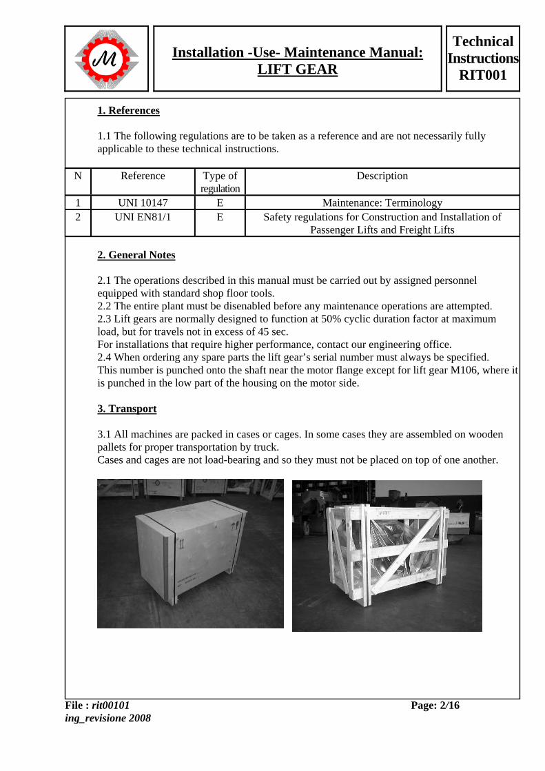
3. Transport 3.1 All machines are packed in cases or cages. In some cases they are assembled on wooden pallets for proper transportation by truck. Cases and cages are not load-bearing and so they must not be placed on top of one another.
Installation -Use- Maintenance Manual: LIFT GEAR
Technical Instructions
RIT001
File : rit00101 ing_revisione 2008
Page: 3/16
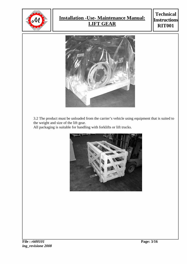
3.2 The product must be unloaded from the carrier’s vehicle using equipment that is suited to the weight and size of the lift gear. All packaging is suitable for handling with forklifts or lift trucks.
Installation -Use- Maintenance Manual: LIFT GEAR
Technical Instructions
RIT001
File : rit00101 ing_revisione 2008
Page: 4/16
Lift gear type Maximum weight (kg.) M74I 250 M73 - M73S - M75 - M75S – M75V – M75VS 350 M73AL – M75AL 410 M83 – M85 500 M83AL 580 M93 650 M93AL 700 M98 900 M98AL 1000 M104/M104B9 1800 M106 – M106S2 – M106B3 2500 Notes: The weights shown are to be considered as maximum, but not inclusive of any bedframe or casings related to the lift gear
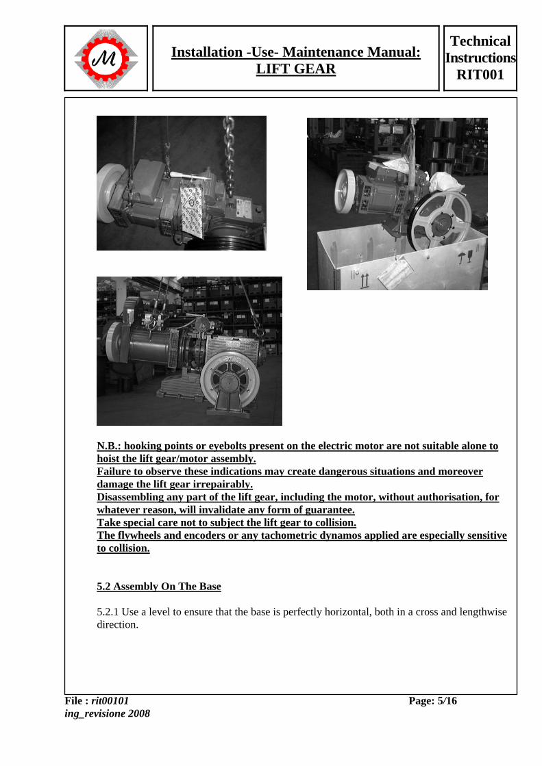
3.3 Each delivery of material should be checked to assess its condition. If damage is noted, you must not install the equipment unless we authorise you to do so. 4. Storage 4.1 Even if the lift gears are still packaged, they should be stored in dry places protected from bad weather conditions. 4.2 After disposing of packaging ensure that dust does not settle on the equipment. 5. Installation 5.1 Handling 5.1.1 The lift gear may be handled using belts or chains but ensure that you do not load weight on critical areas. Critical areas are: - shafts that protrude from electric motors, with or without flywheels - all braking components: brake drum, shoes, electromagnets, pins with springs. - lift gear/motor couplings. - flanges for tachometric dynamo or encoders. Hoisting examples
Installation -Use- Maintenance Manual: LIFT GEAR
Technical Instructions
RIT001
File : rit00101 ing_revisione 2008
Page: 5/16
N.B.: hooking points or eyebolts present on the electric motor are not suitable alone to hoist the lift gear/motor assembly. Failure to observe these indications may create dangerous situations and moreover damage the lift gear irrepairably. Disassembling any part of the lift gear, including the motor, without authorisation, for whatever reason, will invalidate any form of guarantee. Take special care not to subject the lift gear to collision. The flywheels and encoders or any tachometric dynamos applied are especially sensitive to collision. 5.2 Assembly On The Base 5.2.1 Use a level to ensure that the base is perfectly horizontal, both in a cross and lengthwise direction.
Installation -Use- Maintenance Manual: LIFT GEAR
Technical Instructions
RIT001
File : rit00101 ing_revisione 2008
Page: 6/16
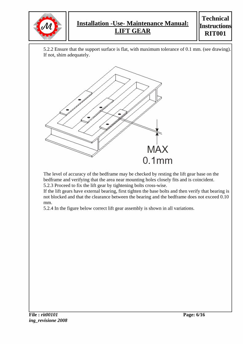
5.2.2 Ensure that the support surface is flat, with maximum tolerance of 0.1 mm. (see drawing). If not, shim adequately.
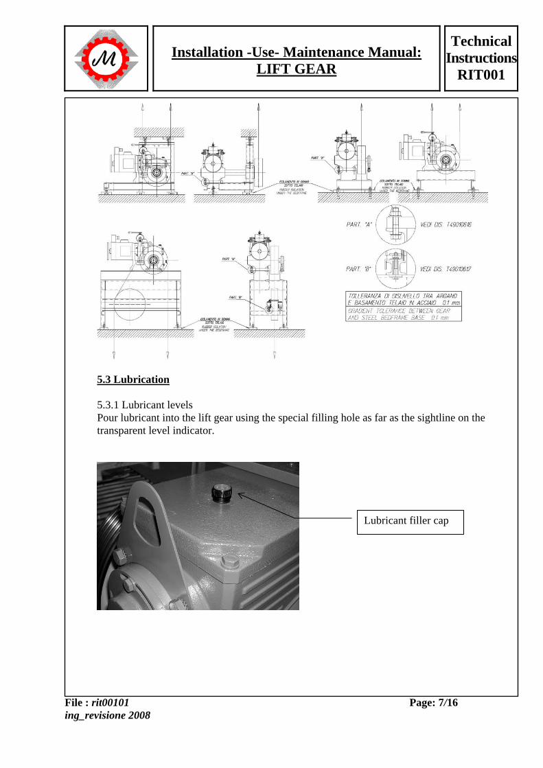
The level of accuracy of the bedframe may be checked by resting the lift gear base on the bedframe and verifying that the area near mounting holes closely fits and is coincident. 5.2.3 Proceed to fix the lift gear by tightening bolts cross-wise. If the lift gears have external bearing, first tighten the base bolts and then verify that bearing is not blocked and that the clearance between the bearing and the bedframe does not exceed 0.10 mm. 5.2.4 In the figure below correct lift gear assembly is shown in all variations.
Installation -Use- Maintenance Manual: LIFT GEAR
Technical Instructions
RIT001
File : rit00101 ing_revisione 2008
Page: 7/16
5.3 Lubrication 5.3.1 Lubricant levels Pour lubricant into the lift gear using the special filling hole as far as the sightline on the transparent level indicator.
Lubricant filler cap
Installation -Use- Maintenance Manual: LIFT GEAR
Technical Instructions
RIT001
File : rit00101 ing_revisione 2008
Page: 8/16
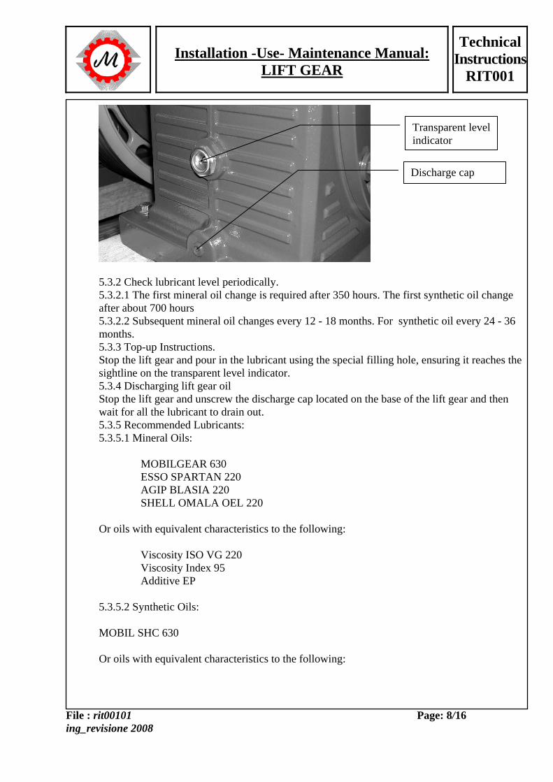
5.3.2 Check lubricant level periodically. 5.3.2.1 The first mineral oil change is required after 350 hours. The first synthetic oil change after about 700 hours 5.3.2.2 Subsequent mineral oil changes every 12 - 18 months. For synthetic oil every 24 - 36 months. 5.3.3 Top-up Instructions. Stop the lift gear and pour in the lubricant using the special filling hole, ensuring it reaches the sightline on the transparent level indicator. 5.3.4 Discharging lift gear oil Stop the lift gear and unscrew the discharge cap located on the base of the lift gear and then wait for all the lubricant to drain out. 5.3.5 Recommended Lubricants: 5.3.5.1 Mineral Oils: MOBILGEAR 630 ESSO SPARTAN 220 AGIP BLASIA 220 SHELL OMALA OEL 220 Or oils with equivalent characteristics to the following: Viscosity ISO VG 220 Viscosity Index 95 Additive EP 5.3.5.2 Synthetic Oils: MOBIL SHC 630 Or oils with equivalent characteristics to the following:
Transparent level indicator
Discharge cap
Installation -Use- Maintenance Manual: LIFT GEAR
Technical Instructions
RIT001
File : rit00101 ing_revisione 2008
Page: 9/16
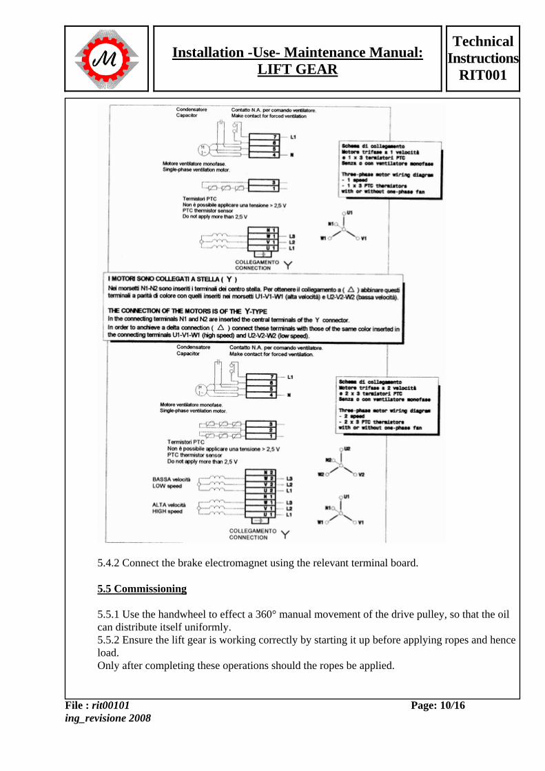
Viscosity ISO VG 220 Viscosity Index 151 Ascertained compatibility with traces of mineral oil. 5.3.6 Check lubricant level in the electric motor periodically. 5.3.6.1 For motors with bronze bushes and hence with oil tanks, follow the same instructions for changing and topping up lift gear lubricant. 5.3.6.2 The types of oil recommended are the same used for the lift gears, unless otherwise stated on the motors themselves. 5.3.6.3 Ensure there are no traces of oil on the brake drum or on the brake shoes. 5.4 Electrical Wiring 5.4.1 Wire up the electrical motor following the indications on the wiring diagram in the terminal box. The example we include here is for wiring ELEMOL motors.
Installation -Use- Maintenance Manual: LIFT GEAR
Technical Instructions
RIT001
File : rit00101 ing_revisione 2008
Page: 10/16
5.4.2 Connect the brake electromagnet using the relevant terminal board. 5.5 Commissioning 5.5.1 Use the handwheel to effect a 360° manual movement of the drive pulley, so that the oil can distribute itself uniformly. 5.5.2 Ensure the lift gear is working correctly by starting it up before applying ropes and hence load. Only after completing these operations should the ropes be applied.
Installation -Use- Maintenance Manual: LIFT GEAR
Technical Instructions
RIT001
File : rit00101 ing_revisione 2008
Page: 11/16
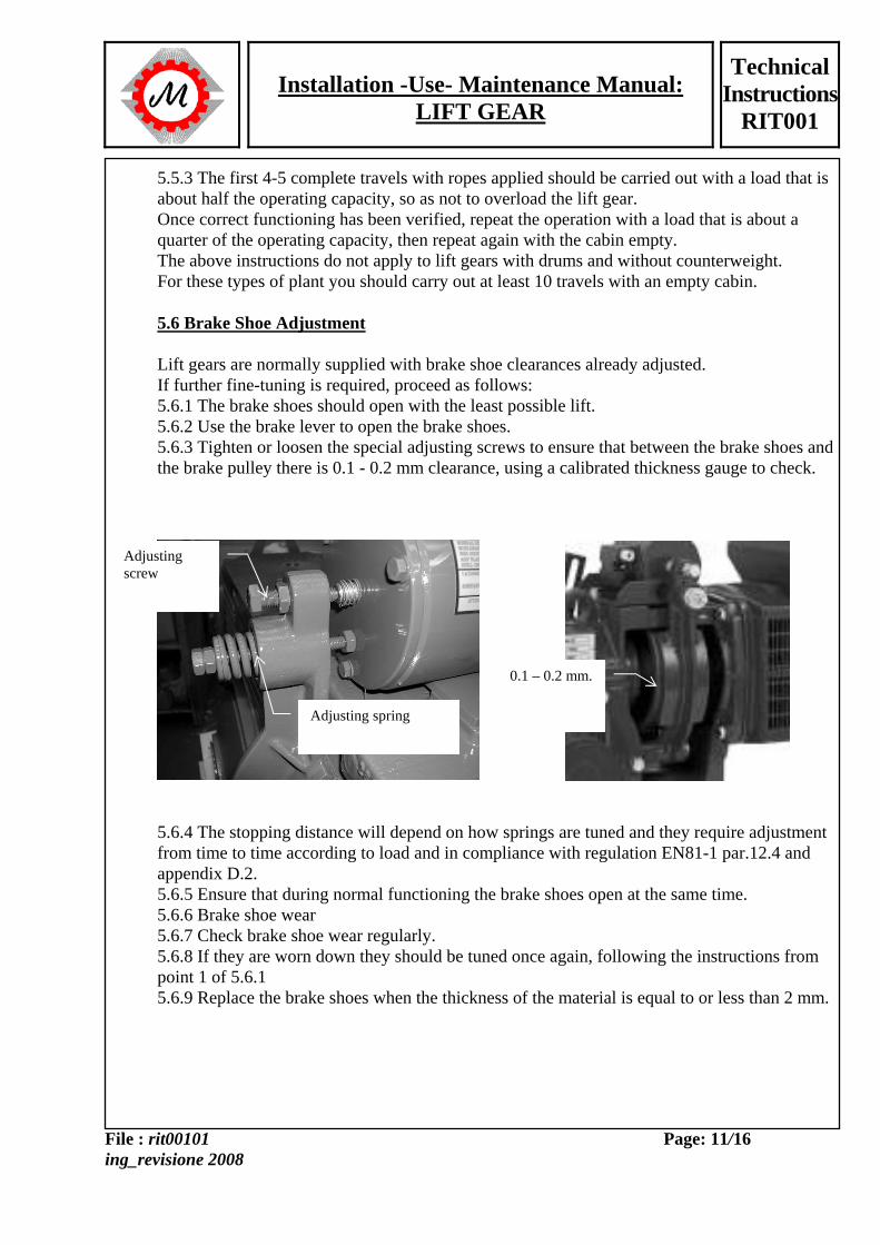
5.5.3 The first 4-5 complete travels with ropes applied should be carried out with a load that is about half the operating capacity, so as not to overload the lift gear. Once correct functioning has been verified, repeat the operation with a load that is about a quarter of the operating capacity, then repeat again with the cabin empty. The above instructions do not apply to lift gears with drums and without counterweight. For these types of plant you should carry out at least 10 travels with an empty cabin. 5.6 Brake Shoe Adjustment Lift gears are normally supplied with brake shoe clearances already adjusted. If further fine-tuning is required, proceed as follows: 5.6.1 The brake shoes should open with the least possible lift. 5.6.2 Use the brake lever to open the brake shoes. 5.6.3 Tighten or loosen the special adjusting screws to ensure that between the brake shoes and the brake pulley there is 0.1 - 0.2 mm clearance, using a calibrated thickness gauge to check.
5.6.4 The stopping distance will depend on how springs are tuned and they require adjustment from time to time according to load and in compliance with regulation EN81-1 par.12.4 and appendix D.2. 5.6.5 Ensure that during normal functioning the brake shoes open at the same time. 5.6.6 Brake shoe wear 5.6.7 Check brake shoe wear regularly. 5.6.8 If they are worn down they should be tuned once again, following the instructions from point 1 of 5.6.1 5.6.9 Replace the brake shoes when the thickness of the material is equal to or less than 2 mm.
Adjusting screw
Adjusting spring
0.1 – 0.2 mm.
Installation -Use- Maintenance Manual: LIFT GEAR
Technical Instructions
RIT001
File : rit00101 ing_revisione 2008
Page: 12/16
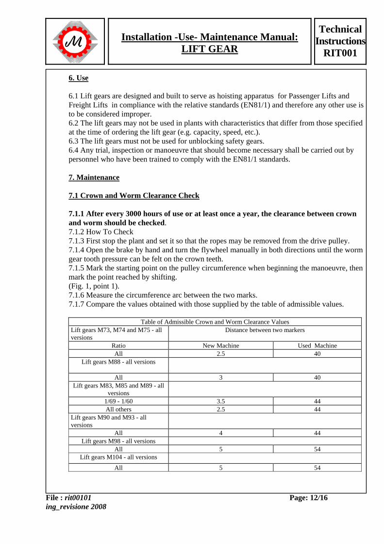
6. Use 6.1 Lift gears are designed and built to serve as hoisting apparatus for Passenger Lifts and Freight Lifts in compliance with the relative standards (EN81/1) and therefore any other use is to be considered improper. 6.2 The lift gears may not be used in plants with characteristics that differ from those specified at the time of ordering the lift gear (e.g. capacity, speed, etc.). 6.3 The lift gears must not be used for unblocking safety gears. 6.4 Any trial, inspection or manoeuvre that should become necessary shall be carried out by personnel who have been trained to comply with the EN81/1 standards. 7. Maintenance 7.1 Crown and Worm Clearance Check 7.1.1 After every 3000 hours of use or at least once a year, the clearance between crown and worm should be checked. 7.1.2 How To Check 7.1.3 First stop the plant and set it so that the ropes may be removed from the drive pulley. 7.1.4 Open the brake by hand and turn the flywheel manually in both directions until the worm gear tooth pressure can be felt on the crown teeth. 7.1.5 Mark the starting point on the pulley circumference when beginning the manoeuvre, then mark the point reached by shifting. (Fig. 1, point 1). 7.1.6 Measure the circumference arc between the two marks. 7.1.7 Compare the values obtained with those supplied by the table of admissible values.
Table of Admissible Crown and Worm Clearance Values Lift gears M73, M74 and M75 - all versions
Distance between two markers
Ratio New Machine Used Machine All 2.5 40
Lift gears M88 - all versions
All 3 40 Lift gears M83, M85 and M89 - all
versions
1/69 - 1/60 3.5 44 All others 2.5 44
Lift gears M90 and M93 - all versions
All 4 44 Lift gears M98 - all versions
All 5 54 Lift gears M104 - all versions
All 5 54
Installation -Use- Maintenance Manual: LIFT GEAR
Technical Instructions
RIT001
File : rit00101 ing_revisione 2008
Page: 13/16
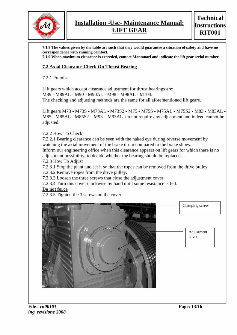
7.1.8 The values given by the table are such that they would guarantee a situation of safety and have no correspondence with running comfort. 7.1.9 When maximum clearance is exceeded, contact Montanari and indicate the lift gear serial number. 7.2 Axial Clearance Check On Thrust Bearing 7.2.1 Premise Lift gears which accept clearance adjustment for thrust bearings are: M89 - M89AL - M90 - M90AL - M98 - M98AL - M104. The checking and adjusting methods are the same for all aforementioned lift gears. Lift gears M73 - M73S - M73AL - M73S2 - M75 - M75S - M75AL - M75S2 - M83 - M83AL - M85 - M85AL - M85S2 – M93 – M93AL do not require any adjustment and indeed cannot be adjusted. 7.2.2 How To Check 7.2.2.1 Bearing clearance can be seen with the naked eye during reverse movement by watching the axial movement of the brake drum compared to the brake shoes. Inform our engineering office when this clearance appears on lift gears for which there is no adjustment possibility, to decide whether the bearing should be replaced. 7.2.3 How To Adjust 7.2.3.1 Stop the plant and set it so that the ropes can be removed from the drive pulley 7.2.3.2 Remove ropes from the drive pulley. 7.2.3.3 Loosen the three screws that close the adjustment cover. 7.2.3.4 Turn this cover clockwise by hand until some resistance is felt. Do not force 7.2.3.5 Tighten the 3 screws on the cover
Clamping screw
Adjustment cover
Installation -Use- Maintenance Manual: LIFT GEAR
Technical Instructions
RIT001
File : rit00101 ing_revisione 2008
Page: 14/16
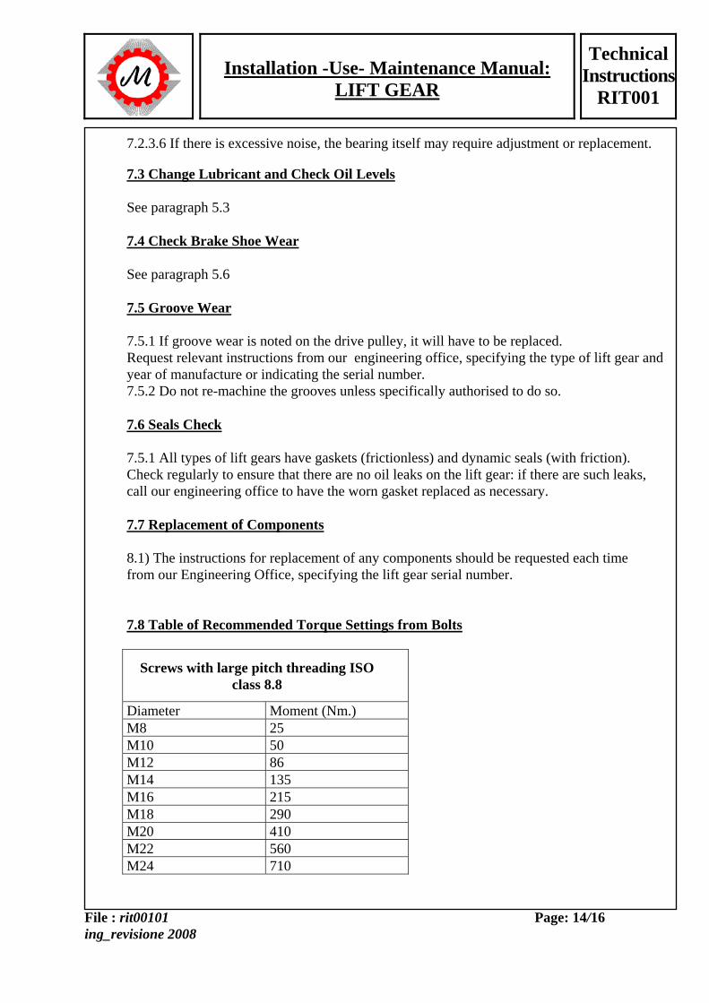
7.2.3.6 If there is excessive noise, the bearing itself may require adjustment or replacement. 7.3 Change Lubricant and Check Oil Levels See paragraph 5.3 7.4 Check Brake Shoe Wear See paragraph 5.6 7.5 Groove Wear 7.5.1 If groove wear is noted on the drive pulley, it will have to be replaced. Request relevant instructions from our engineering office, specifying the type of lift gear and year of manufacture or indicating the serial number. 7.5.2 Do not re-machine the grooves unless specifically authorised to do so. 7.6 Seals Check 7.5.1 All types of lift gears have gaskets (frictionless) and dynamic seals (with friction). Check regularly to ensure that there are no oil leaks on the lift gear: if there are such leaks, call our engineering office to have the worn gasket replaced as necessary. 7.7 Replacement of Components 8.1) The instructions for replacement of any components should be requested each time from our Engineering Office, specifying the lift gear serial number. 7.8 Table of Recommended Torque Settings from Bolts
Screws with large pitch threading ISO class 8.8
Diameter Moment (Nm.) M8 25 M10 50 M12 86 M14 135 M16 215 M18 290 M20 410 M22 560 M24 710
Installation -Use- Maintenance Manual: LIFT GEAR
Technical Instructions
RIT001
File : rit00101 ing_revisione 2008
Page: 15/16
Installation -Use- Maintenance Manual: LIFT GEAR
Technical Instructions
RIT001
File : rit00101 ing_revisione 2008
Page: 16/16
8. Declaration of conformity
DECLARATION OF CONFORMITY (Directive 98/37/CE, Art. 4.2 and Enclosure II, par. B.)
It is hereby declared that lift gear models: M73 – M73B - M73S – M73SB – M73S2 – M73S2B - M73AL – M73ALB – M73AL2 – M73AL2B - M75 – M75B - M75S – M75SB - M75S2 – M75S2B - M75AL – M75ALB - M75AL2 – M75AL2B - M75T – M83 – M83B - M83AL – M83ALB – M83T – M85 – M85B - M85S2 – M85S2B - M93 – M93B - M93AL – M93ALB - M93T – M98 – M98B - M98AL - M104 – M104B - M104AL - M104B9 – M104B9B - M104B9AL– M106 – M106S2 - M106B3. - are built to be incorporated in a existing plant or to be assembled with other components to construct a new plant under Directive 98/37/CE and subsequent modifications; - however, they do not comply with each single disposition in this directive; - they do, however, comply with the conditions in these other directives 95/16/CE and 89/336/EEC and that - the following harmonized regulations (parts/clauses of) were applied: EN81.1; EN55011; EN55014; EN50081-2; EN12015/6. Moreover, we declare that - the lift gear should not be started up until the existing or new plant in which it is built in has been tested and has been declared compliant with Directive 95/16/CE or with Directive 98/37/CE as well as with domestic legislation that transposes it, that is to say until the lift gear inherent to this declaration forms a single unit with the overall plant. Violation of the dispositions given in these technical instructions will immediately invalidate any form of guarantee. Note: With regard to fulfilment of point 9.7 of reference regulation EN81-1 1998, please remember that Montanari supplies protection devices only if specifically requested by the customer. Person-in-charge Date 04/01/08