Embed Size (px)
Citation preview

Technical Manual 1
Design of Monopole Bases
By Daniel Horn, P.E.

Copyright 2011 by Tower Numerics Inc. All rights reserved.
www.towernx.com
Care has been taken to ensure that the material found in this publication is both useful
and accurate. However, please be aware that errors may exist in this publication, and that
Tower Numerics Inc. makes no guarantees concerning accuracy of the information found
here or in the use to which it may be put.
Contents
Introduction 1 Organization .............................................................................................................. 1 Historical Perspective ............................................................................................... 2 AISC Method For Building Columns ..................................................................... 7
Flexible Base Plate ........................................................................................ 8 Example 1.1 ................................................................................................... 9 Stiff Plate Approach ................................................................................... 12 Example 1.2 ................................................................................................. 14 Example 1.3 ................................................................................................. 17
Grouted Base Plates 19 Process Equipment Design Method...................................................................... 19
Example 2.1 ................................................................................................. 26 Lutz Modification.................................................................................................... 29
Example 2.2 ................................................................................................. 31 Complete Square Base Plate – Load On Diagonal .............................................. 33
Modification for Clipped Corners............................................................ 36 Example 2.3 ................................................................................................. 38 Example 2.4 ................................................................................................. 43
Complete Square Base Plate – Load Parallel ....................................................... 47 Example 2.4 ................................................................................................. 50
Complete Circular Base Plate Method ................................................................. 54 Example 2.5 ................................................................................................. 58
Ungrouted Base Plates 63 Determining Bolt Forces ......................................................................................... 63
Example 3.1 ................................................................................................. 64 Example 3.2 ................................................................................................. 66 Example 3.3 ................................................................................................. 68
Determining Plate Stresses 71 Introduction.............................................................................................................. 71 Effective Width Based Upon Plate Theory .......................................................... 71 Process Equipment Methods ................................................................................. 72
Example 4.1 ................................................................................................. 74 Base Plates With Gussets........................................................................... 77
Alternate Method 1 ................................................................................................. 79
Technical Manual 1 Design of Monopole Bases Contents • iii
Alternate Method 2 ................................................................................................. 79 Alternate Method 3 ................................................................................................. 79 Method of Slices....................................................................................................... 80
Example 4.2 ................................................................................................. 83 Alternate Method 1 – Square Base Plates............................................................. 87 Alternate Method 2 – Circular Base Plates .......................................................... 87 Boulos Method (New York Dept. of Transportation) ........................................ 87
Diagonal Loading Case.............................................................................. 90 Parallel Loading Case ................................................................................ 91
Owens Method (New York Dept. of Transportation) ........................................ 94 ASCE Manual 72 (Proposed 2003 Revision) ........................................................ 95
Example 4.3 ................................................................................................. 96
Anchor Bolts 99 Material Grades ....................................................................................................... 99 Anchorage .............................................................................................................. 101
Example 4.1 ............................................................................................... 103
Recommendations 105 Determining Base Plate Forces ............................................................................ 105
Grouted Base Plates ................................................................................. 105 Ungrouted Base Plates............................................................................. 105
Determining Base Plate Stresses.......................................................................... 105 Construction Details.............................................................................................. 107
Bibliography 108 References............................................................................................................... 108
Glossary of Terms 111
Index 113
iv • Contents Technical Manual 1 Design of Monopole Bases
Technical Manual 1 Design of Monopole Bases Introduction • 1
Introduction
Organization
The following chapters will cover the following topics:
1. An historical perspective including the AISC approach to base plate design for building columns.
2. Classical methods for determining bolt forces and concrete stresses for grouted base plates.
3. Classical methods for determining bolt forces for ungrouted base plates.
4. Evaluation of various methods currently being used to determine base plate bending stresses for plain and stiffened plates
Technical Manual 1 – Design of Monopole Bases Introduction • 2
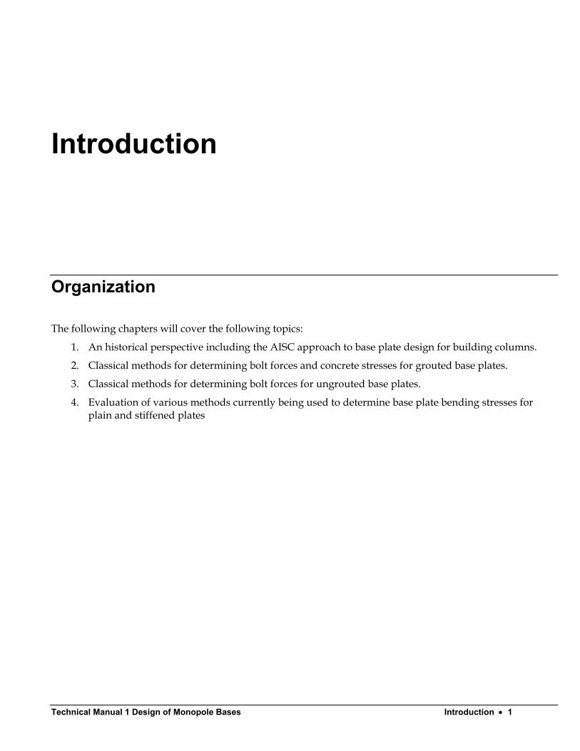
Historical Perspective Monopoles have become increasingly popular for use in the telecommunication industry. The advantages include architectural attractiveness and a minimal use of land. Poles are of two general types, tapered polygonal poles and stepped pipe poles.
The tapered polygonal pole shown in Fig. 1-1, is custom manufactured to exact diameters required for the design. Each section is joined using telescoping lap joints.
Fig. 1- 1

Technical Manual 1 Design of Monopole Bases Introduction • 3
Pipe poles are made from large diameter pipe sections and joined by external or internal flange connections as shown in Fig. 1-2.
Fig. 1- 2
While some poles may be directly buried into the earth, the most common method of attaching the pole to the foundation is with a base plate.
Technical Manual 1 – Design of Monopole Bases Introduction • 4
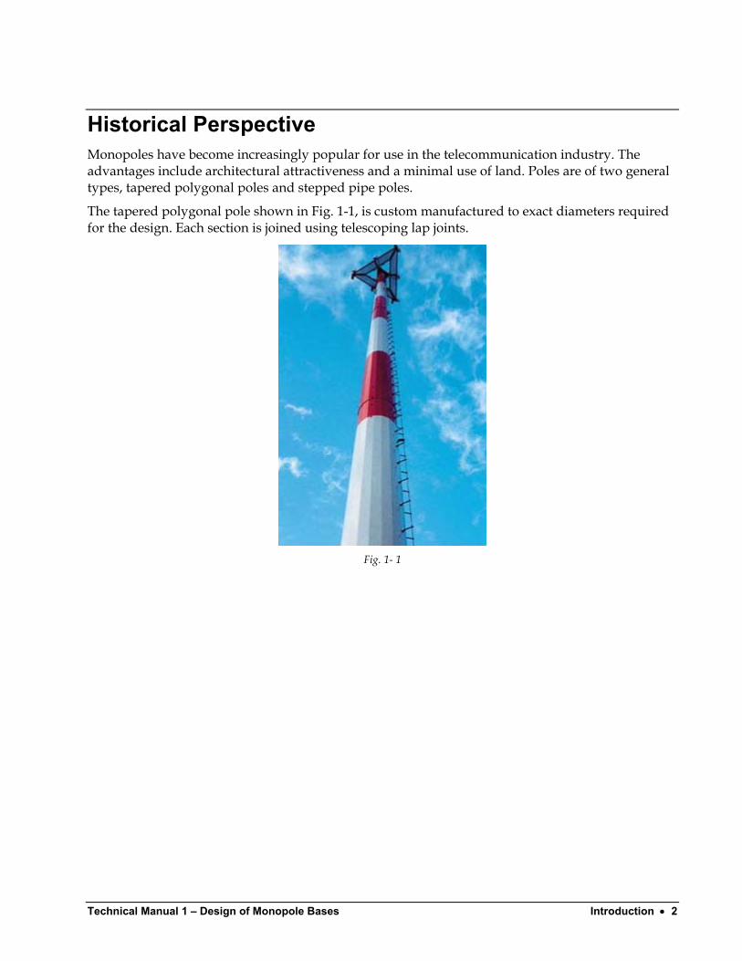
Base plates can be square with clustered anchor bolts as shown in Fig. 1-3 when overturning moments are relatively light.
Fig. 1- 3
The clear space below the leveling nut is not limited by the TIA-222 Standard; however, the ASCE Manual(1) suggests limiting the distance to two bolt diameters. AASHTO(2) limits this distance to one bolt diameter. AASHTO also recommends that the minimum base plate thickness be equal to the bolt diameter.
Technical Manual 1 Design of Monopole Bases Introduction • 5
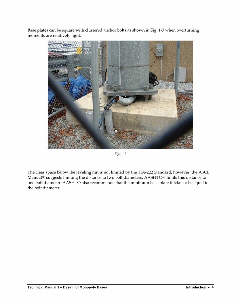
Base plates can also be polygonal or circular to accommodate a larger number of bolts. The plate may need to have gusset plates (stiffeners) in order to transfer forces due to axial and bending moment to the pole. A typical example is shown in Fig. 1-4.
Fig. 1- 4
Poles have been used in the power transmision field since the 1960’s. Prior to that, poles were used almost exclusively for flags(3,4) and for highway structures(2). In recent years, poles have become popular for both electric transmission towers and for telecommunication structures.
There is currently no industry standard for the design of pole base plates. Some state highway departments (New York) have developed their own methods, but no national standard exists. As such, the designer is left to arrive at appropriate methods based upon classical structural mechanics. While some testing has been done on smaller pole base plates used in highway construction (usually poles between 10 and 20 inches in diameter), no testing has been done on larger diameter pole base plates such as used in the telecommunication industry (poles 36 to 72 inches in diameter). Therefore, such design techniques may or may not be appropriate. Recent finite element studies(5,6,7) have indicated that current design practices used by pole manufacturers may be under-designed by 20 to 30%.
Technical Manual 1 – Design of Monopole Bases Introduction • 6
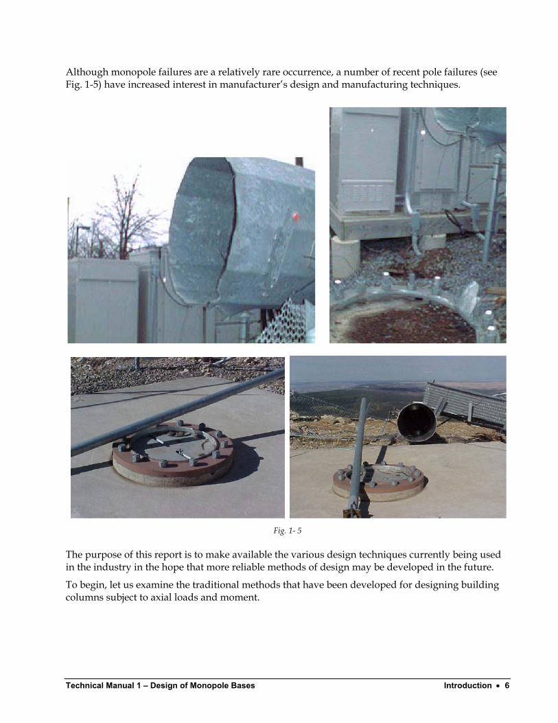
Although monopole failures are a relatively rare occurrence, a number of recent pole failures (see Fig. 1-5) have increased interest in manufacturer’s design and manufacturing techniques.
Fig. 1- 5
The purpose of this report is to make available the various design techniques currently being used in the industry in the hope that more reliable methods of design may be developed in the future.
To begin, let us examine the traditional methods that have been developed for designing building columns subject to axial loads and moment.
Technical Manual 1 Design of Monopole Bases Introduction • 7
AISC Method For Building Columns Moment resisting base plates for building columns are covered in neither the AISC Specification nor the Manual of Steel Construction. Engineers must therefore refer to textbooks or technical papers for design methods although not all texts cover this topic.
Working stress methods for analyzing moment resistant base plate can be found in engineering texts(8,9,10,11,12). DeWolf(13) and Thambiratnam(14) compared methods of designing building columns to test data.
The AISC method for designing axially loaded base plates defines the critical section as being at .95 times the depth of the structural members for shapes of rectangular cross-section such as wide flanges and tubes. The critical section for pipe is defined at a location equal to .80 times the diameter of the pipe.
Two different approaches have been taken to determine the distribution of forces on the base plate, a flexible plate approach and a stiff plate approach.
Technical Manual 1 – Design of Monopole Bases Introduction • 8
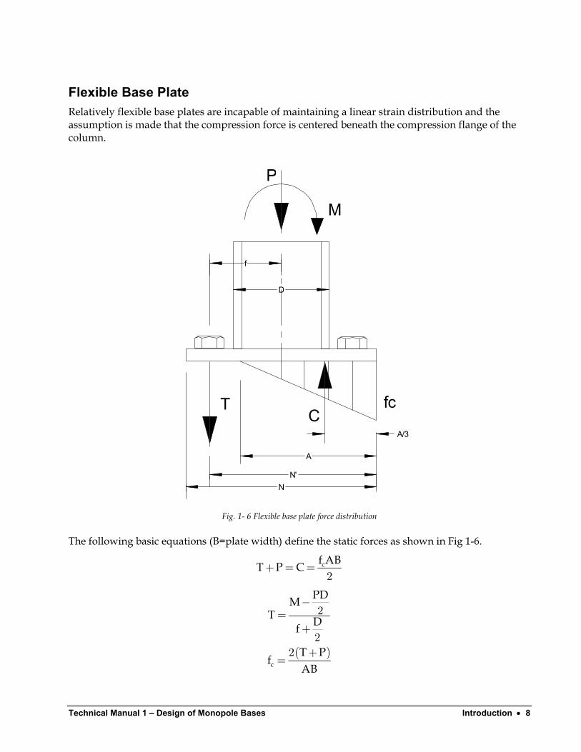
Flexible Base Plate Relatively flexible base plates are incapable of maintaining a linear strain distribution and the assumption is made that the compression force is centered beneath the compression flange of the column.
N
A
N'
D
P
M
T fc
f
CA/3
Fig. 1- 6 Flexible base plate force distribution
The following basic equations (B=plate width) define the static forces as shown in Fig 1-6.
cf ABT P C+ = =2
( )c
PDMT Df
T Pf
AB
−=
+
+=
2
22
Technical Manual 1 Design of Monopole Bases Introduction • 9
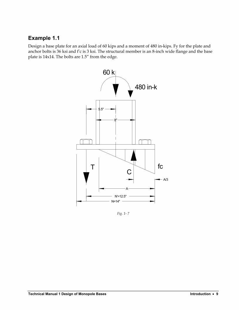
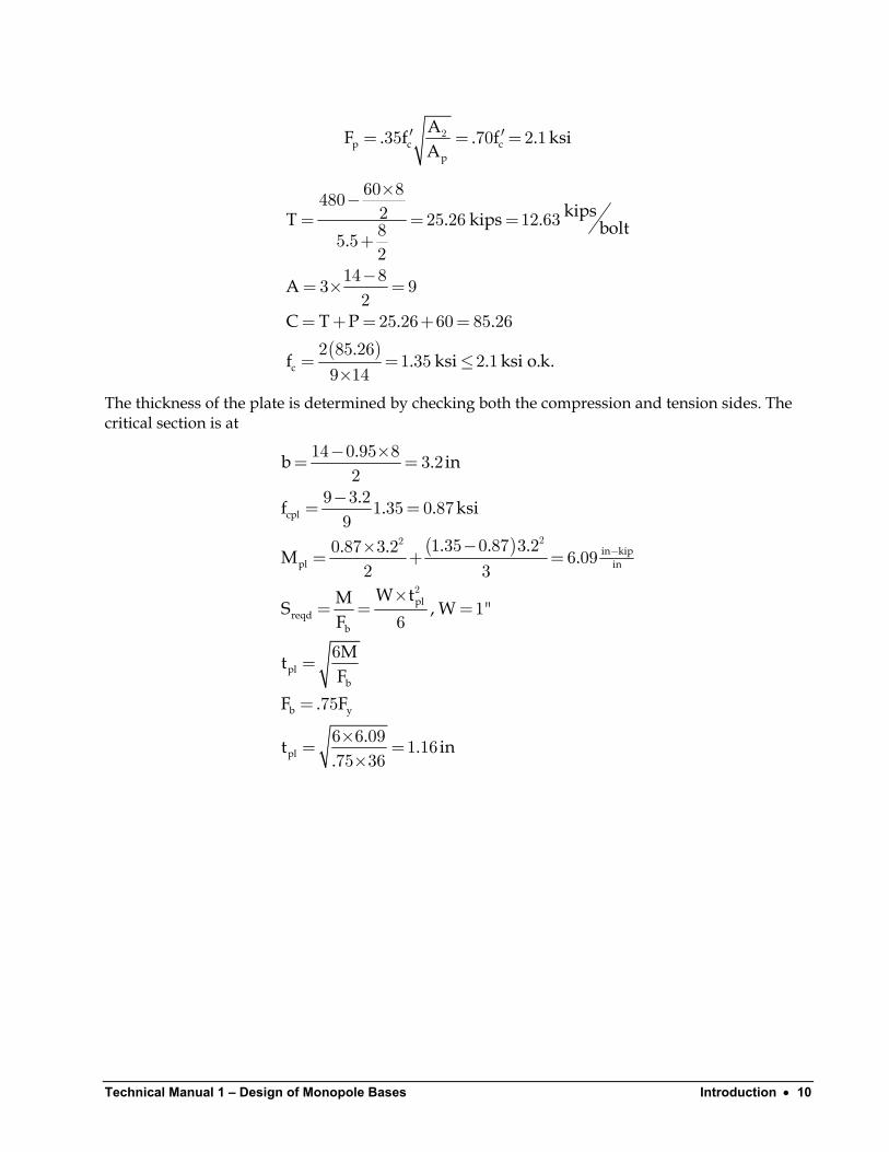
Example 1.1 Design a base plate for an axial load of 60 kips and a moment of 480 in-kips. Fy for the plate and anchor bolts is 36 ksi and f’c is 3 ksi. The structural member is an 8-inch wide flange and the base plate is 14x14. The bolts are 1.5” from the edge.
N=14"
A
N'=12.5"
8"
60 k
480 in-k
T fc
5.5"
CA/3
Fig. 1- 7
Technical Manual 1 – Design of Monopole Bases Introduction • 10
p c cp
AF . f . f . ksA
′ ′= = =235 70 2 1 i
( )c
kipsT . kips . bolt.
A
C T P . ..
f . ksi . ksi o.k.
×−= = =
+
−= × =
= + = + =
= = ≤×
60 84802 25 26 12 6385 52
14 83 9225 26 60 85 26
2 85 261 35 2 1
9 14
The thickness of the plate is determined by checking both the compression and tension sides. The critical section is at
( )
cpl
in kippl in
plreqd
b
plb
b y
pl
.b . in
.f . . ksi
. . .. .M .
W tMS , W "F
MtF
F . F
.t . in.
−
− ×= =
−= =
−×= + =
×= = =
=
=
×= =×
22
2
14 0 95 8 3 22
9 3 21 35 0 879
1 35 0 87 3 20 87 3 2 6 092 3
16
6
75
6 6 09 1 1675 36
Technical Manual 1 Design of Monopole Bases Introduction • 11
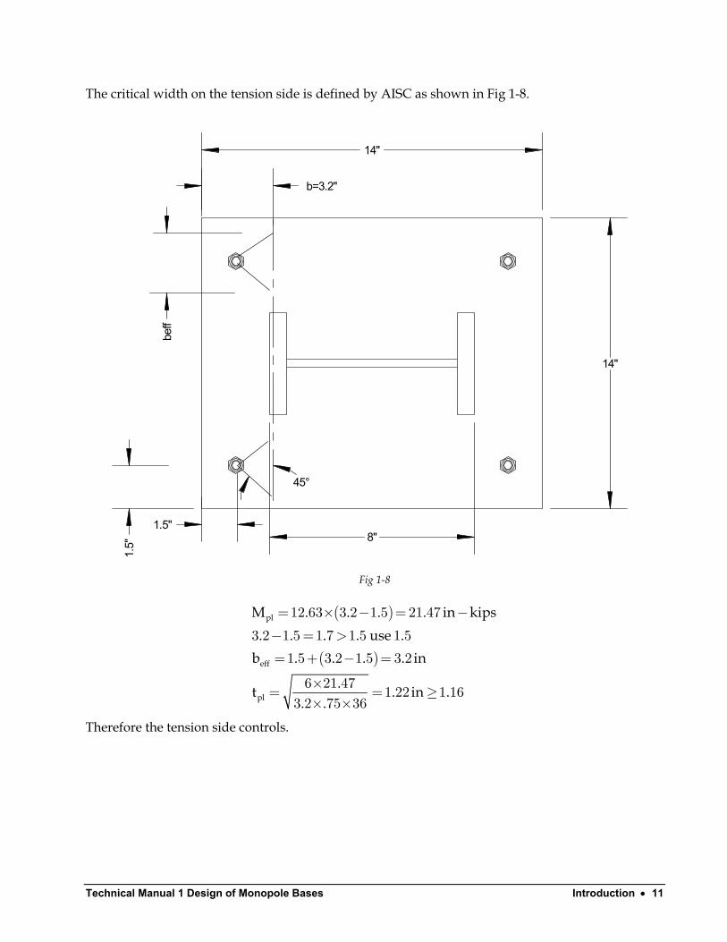
The critical width on the tension side is defined by AISC as shown in Fig 1-8.
beff
b=3.2"
1.5"
45°
14"
14"
8"
1.5"
Fig 1-8
( )
( )
pl
eff
pl
M . . . . in ki. . . . use .
b . . . . in
.t . in. .
= × − = −− = >= + − =
×= = ≥× ×
12 63 3 2 1 5 21 47
3 2 1 5 1 7 1 5 1 51 5 3 2 1 5 3 2
6 21 47 1 22 1 163 2 75 36
ps
.
Therefore the tension side controls.
Technical Manual 1 – Design of Monopole Bases Introduction • 12
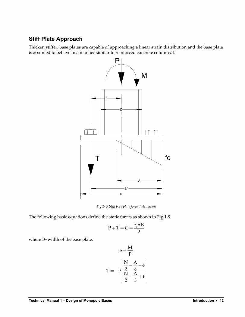
Stiff Plate Approach Thicker, stiffer, base plates are capable of approaching a linear strain distribution and the base plate is assumed to behave in a manner similar to reinforced concrete columns(8).
N
A
N'
D
P
M
T fc
f
Fig 1- 9 Stiff base plate force distribution
The following basic equations define the static forces as shown in Fig 1-9.
cf ABP T C+ = =2
where B=width of the base plate.
MeP
=
N A eT P N A f
− − =− − +
2 3
2 3
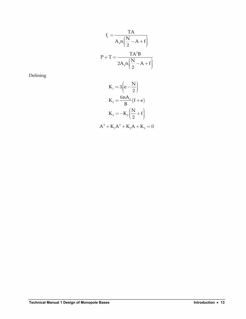
Technical Manual 1 Design of Monopole Bases Introduction • 13
c
s
TAfNA n A f
= − + 2
s
TA BP TNA n A f
+ = − +
2
22
Defining
( )s
NK e
nAK fB
NK K
= −
= +
=− +
1
2
3 2
32
6
2
e
f
A K A K A K+ + + =3 21 2 3 0
Technical Manual 1 – Design of Monopole Bases Introduction • 14
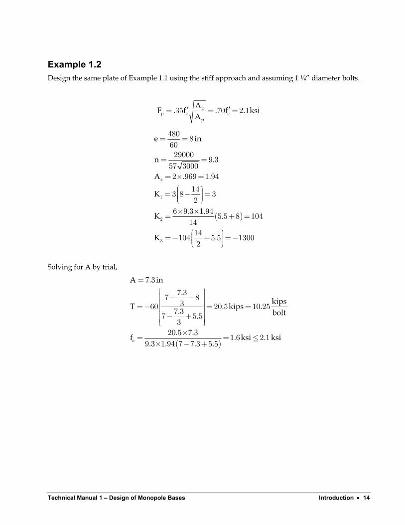
Example 1.2 Design the same plate of Example 1.1 using the stiff approach and assuming 1 ¼” diameter bolts.
p c cp
AF . f . f . ksA
′ ′= = =235 70 2 1 i
( )
s
e in
n .
A . .
K
. .K .
K .
= =
= =
= × = = − = × ×= +
=− + =−
1
2
3
480 86029000 9 357 30002 969 1 94
143 8 32
6 9 3 1 94 5 5 8 1041414104 5 5 13002
=
Solving for A by trial,
( )c
A . in.
kipsT . kips. bolt.
. .f . ksi . ksi. . . .
=
− − =− = = − +
×= = ≤× − +
7 37 37 8360 20 5 10 257 37 5 53
20 5 7 3 1 6 2 19 3 1 94 7 7 3 5 5
.
Technical Manual 1 Design of Monopole Bases Introduction • 15
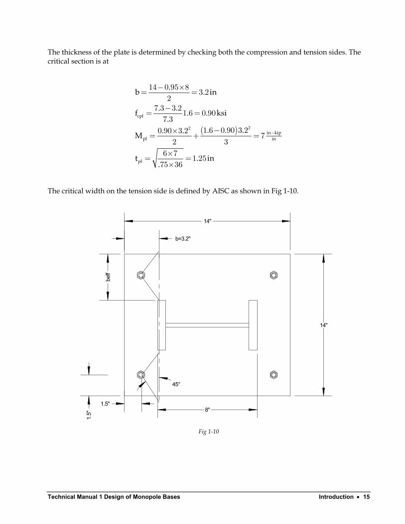
The thickness of the plate is determined by checking both the compression and tension sides. The critical section is at
( )
cpl
in kippl in
pl
.b . in
. .f . . ksi.
. . .. .M
t . in.
−
− ×= =
−= =
−×= + =
×= =×
22
14 0 95 8 3 22
7 3 3 21 6 0 907 3
1 6 0 90 3 20 90 3 2 72 3
6 7 1 2575 36
The critical width on the tension side is defined by AISC as shown in Fig 1-10.
b=3.2"
1.5"
14"
14"
8"
1.5"
45°
beff
Fig 1-10

Technical Manual 1 – Design of Monopole Bases Introduction • 16
( )
( )
pl
eff
pl
M . . . . in kips. . . . in side clearanace use . in
b . . . . in
.t . in . in. .
= × − = −− = >= + − =
×= = ≤× ×
10 25 3 2 1 5 17 43
3 2 1 5 1 7 1 5 1 51 5 3 2 1 5 3 2
6 17 43 1 10 1 253 2 75 36
Therefore the compression side controls.
Technical Manual 1 Design of Monopole Bases Introduction • 17
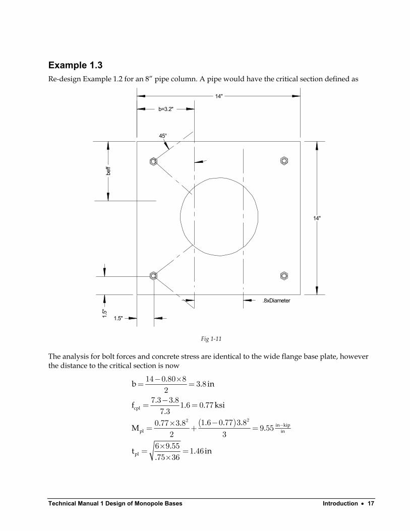
Example 1.3 Re-design Example 1.2 for an 8” pipe column. A pipe would have the critical section defined as
.8xDiameter
beff
1.5"
b=3.2"
45°
14"
14"1.
5"
Fig 1-11
The analysis for bolt forces and concrete stress are identical to the wide flange base plate, however the distance to the critical section is now
( )
cpl
in kippl in
pl
.b . in
. .f . . ksi.
. . .. .M .
.t . in.
−
− ×= =
−= =
−×= + =
×= =×
22
14 0 80 8 3 82
7 3 3 81 6 0 777 3
1 6 0 77 3 80 77 3 8 9 552 3
6 9 55 1 4675 36

Technical Manual 1 – Design of Monopole Bases Introduction • 18
Checking the tension side
( )pl
eff
pl
M . . . . in kips. . . . in side clearance use . in
b . . . in
.t . in .. .
= × − = −− = >= + =
×= = ≤× ×
10 25 3 8 1 5 23 58
3 8 1 5 2 3 1 5 1 51 5 2 3 3 8
6 23 58 1 17 1 463 8 75 36
in
Therefore the compression side controls.
Technical Manual 1 Design of Monopole Bases Grouted Base Plates • 19
Grouted Base Plates
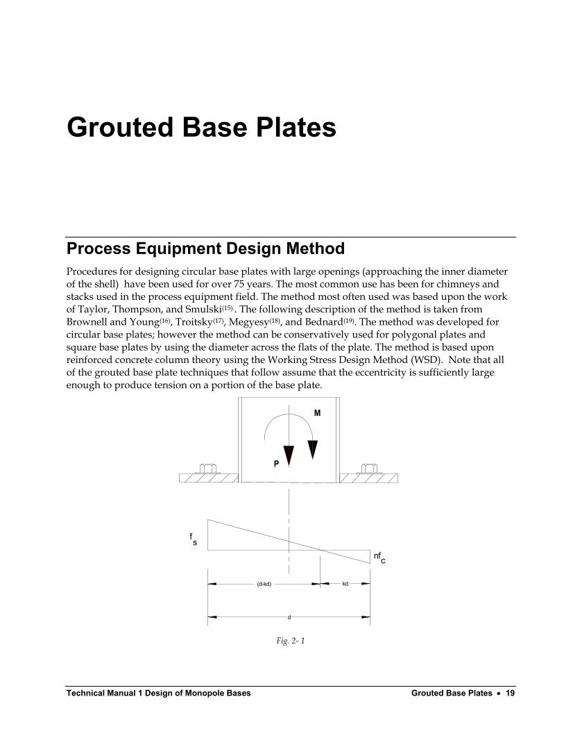
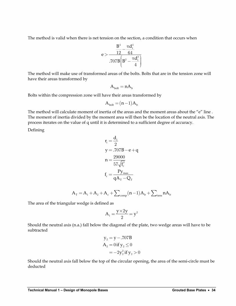
Process Equipment Design Method Procedures for designing circular base plates with large openings (approaching the inner diameter of the shell) have been used for over 75 years. The most common use has been for chimneys and stacks used in the process equipment field. The method most often used was based upon the work of Taylor, Thompson, and Smulski(15).. The following description of the method is taken from Brownell and Young(16), Troitsky(17), Megyesy(18), and Bednard(19). The method was developed for circular base plates; however the method can be conservatively used for polygonal plates and square base plates by using the diameter across the flats of the plate. The method is based upon reinforced concrete column theory using the Working Stress Design Method (WSD). Note that all of the grouted base plate techniques that follow assume that the eccentricity is sufficiently large enough to produce tension on a portion of the base plate.
fs
c
d
(d-kd) kd
P
M
nf
Fig. 2- 1
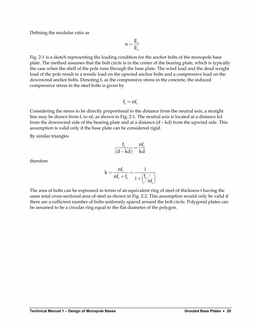
Technical Manual 1 – Design of Monopole Bases Grouted Base Plates • 20
Defining the modular ratio as
= s
c
EnE
Fig. 2-1 is a sketch representing the loading condition for the anchor bolts of the monopole base plate. The method assumes that the bolt circle is in the center of the bearing plate, which is typically the case when the shell of the pole runs through the base plate. The wind load and the dead weight load of the pole result in a tensile load on the upwind anchor bolts and a compressive load on the downwind anchor bolts. Denoting fc as the compressive stress in the concrete, the induced compressive stress in the steel bolts is given by
sf n= cf
Considering the stress to be directly proportional to the distance from the neutral axis, a straight line may be drawn from fs to nfc as shown in Fig. 2-1. The neutral axis is located at a distance kd from the downwind side of the bearing plate and at a distance (d – kd) from the upwind side. This assumption is valid only if the base plate can be considered rigid.
By similar triangles
( )
sfd kd kd
=−
cnf
therefore
( )
c
sc sc
nfkfnf f
nf
= =+ +
1
1
The area of bolts can be expressed in terms of an equivalent ring of steel of thickness t having the same total cross-sectional area of steel as shown in Fig. 2-2. This assumption would only be valid if there are a sufficient number of bolts uniformly spaced around the bolt circle. Polygonal plates can be assumed to be a circular ring equal to the flat diameter of the polygon.
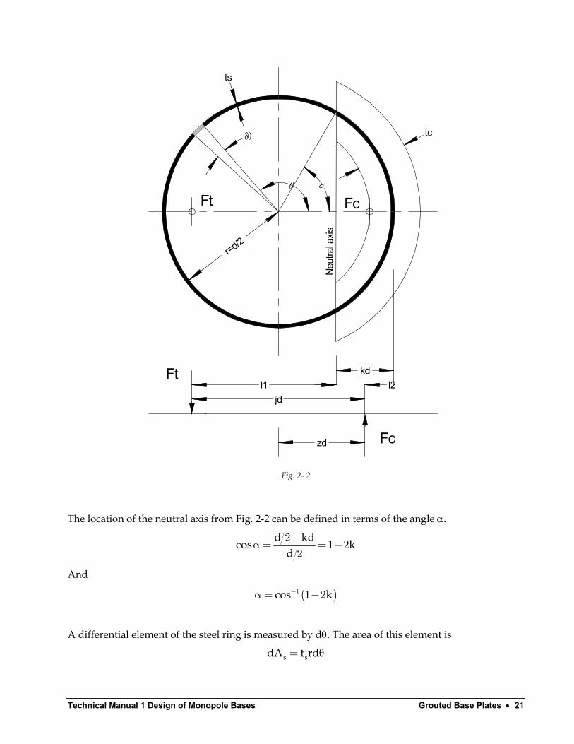
Technical Manual 1 Design of Monopole Bases Grouted Base Plates • 21
δθ
ts
tc
θ αr=d/2
Ft Fc
Neut
ral a
xis
kdl1 l2
jd
zd
Ft
Fc
Fig. 2- 2
The location of the neutral axis from Fig. 2-2 can be defined in terms of the angle α.
d kdcos k
d−α= = −2
1 22
And
(cos k−α= −1 1 2 )
A differential element of the steel ring is measured by dθ. The area of this element is
s sdA t rd= θ
Technical Manual 1 – Design of Monopole Bases Grouted Base Plates • 22
where
r d= 2
The distance from the neutral axis to this differential element is
r(cos cos )α+ θ
Denoting the maximum steel stress as fs, the stress in the element is
( )( )s s
r cos cosf f
r cosα+ θ′=+ α1
The force in the element is therefore
( )( )t s s s s
cos cosdF dA f f t r
cosα+ θ′= =+ α1
The total tensile force is therefore
( )( )
( )( )( )
t t s s
s s
cos cosF dF f t r
cos
f t r cos sincos
π π
α α
α+ θ= = θ
+ αd
= π−α α+ α + α
∫ ∫2 21
21
s s tf t rC=
where
( )
( )(tC coscos
= π−α α+ α + α
21
)sin
The c.g. of the tensile force, l1, can be located by first determining the moment on the tension side and then dividing by Ft. The moment of the differential element is
( )( ) (
( )( )
)
t t
s s
s s
dM dF r cos cos
cos cosf t r r cos cos d
cos
cos cosf t r d
cos
= α+ θ α+ θ = α+ θ θ + α α+ θ = θ + α
2
1
1
Integrating
( )( )
( ) ( ) ( )
t s s
s s
cos cosM f t r d
cos
cos sin cosf t r
cos
π
α
α+ θ= θ
+ α π−α α+ α α + π−α = + α
∫2
2
2 3 12 2 2
21
21

Technical Manual 1 Design of Monopole Bases Grouted Base Plates • 23
Dividing
( ) ( ) ( )
( )t
t
cos sin cosMl rF cos sin
π−α α+ α α + π−α = = π−α α+ α
2 3 12 2
1
The values of α, Ct and l1 are constants for a given value of k.
Values for the compression area follow a similar formulation. The width of the compression ring is defined as . The differential element for a compression ring of thickness tc plt b t= − s
)
c is
c cdA t rd= θ
The distance from the neutral axis to this element is
(r cos cosθ− α
The maximum distance from the neutral axis is
( )r cos− α1
The element stress is directly proportional to the distance from the neutral axis
( )( )c c
r cos cosf f
r cosθ− α′=− α1
The compressive stress in the steel is
( )( )sc c
cos cosf nf
cosθ− α′ =− α1
The force is determined by multiplying by the element areas
c c c c ccos cosdF f dA f t r d
cos θ− α′= = θ − α 1
sc sc s c scos cosdF nf dA nf t r d
cos θ− α′= = θ − α 1
The total is therefore
( )ctot c s ccos cosdF t nt rf d
cos θ− α= + θ − α 1
Integrating
( )
( ) ( )
c c s c
c c s c
cos cosF t nt rf dcos
sin cosF t nt rf
cos
α θ− α= + θ− α
α−α α = + − α
∫02 121
( )c c s cF t nt rf C= + c
Conversely
Technical Manual 1 – Design of Monopole Bases Grouted Base Plates • 24
( )
cc
c s
Fft nt rC
=+ c
Where
csin cosC
cos α−α α= − α 2
1
The c.g. of the compressive force, l2, can be located by first determining the moment on the compression side and then dividing by Fc. The moment of the differential element is
( )
( ) (( )
)c c
c s c
dM dF r cos cos
cos cost nt r f d
cos
= θ− α
θ− α= + θ
− α
22
1
Integrating
( ) ( )
( ) ( )
c c s c
c s c
cos cosM t nt f r d
coscos sin cos
t nt f rcos
α θ− α= + θ
− α α− α α + α = + − α
∫2
2
0
2 3 12 2 2
21
21
Dividing
( )c
c
cos sin cosMl rF sin cos
α α− α α + α = = α−α α
2 3 12
22
The total distance between the forces Ft and Fc is equal to l1+l2. Defining the dimensionless ratio j as
( ) ( )( )
l ljd
cos sin cos sin cos coscos sin sin cos
+=
π−α α+ π−α + α α α− α α+α α = + π−α α+ α α−α α
1 2
2 21 3 1 32 2 2 21 1
2 2
The distance from the neutral axis to the centerline of the pole is
d cosα2
and the distance zd is equal to
dzd l cos= + α2 2
The quantity, z is therefore
sin cos cosz cossin cos
α− α α+α α = α+ α−α α
21 32 21
2
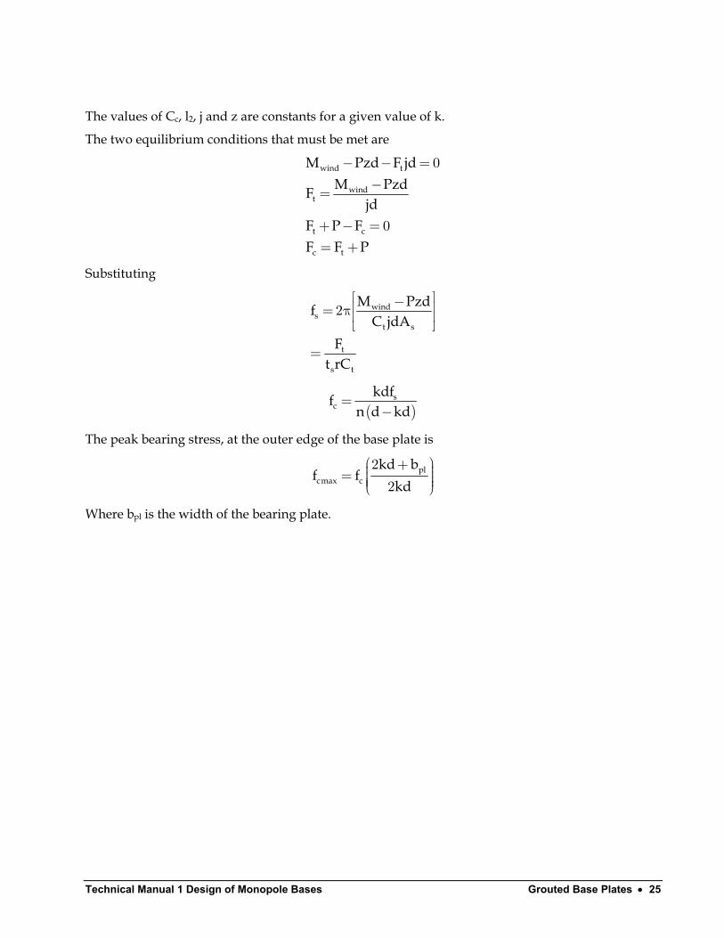
Technical Manual 1 Design of Monopole Bases Grouted Base Plates • 25
The values of Cc, l2, j and z are constants for a given value of k.
The two equilibrium conditions that must be met are
wind t
windt
t c
c t
M Pzd F jdM PzdF
jdF P FF F P
− − =−=
+ − == +
0
0
Substituting
winds
t s
t
s t
M PzfC jdA
Ft rC
d − = π
=
2
( )
sc
kdffn d kd
=−
The peak bearing stress, at the outer edge of the base plate is
plcmax c
kd bf f
kd + = 22
Where bpl is the width of the bearing plate.
Technical Manual 1 – Design of Monopole Bases Grouted Base Plates • 26
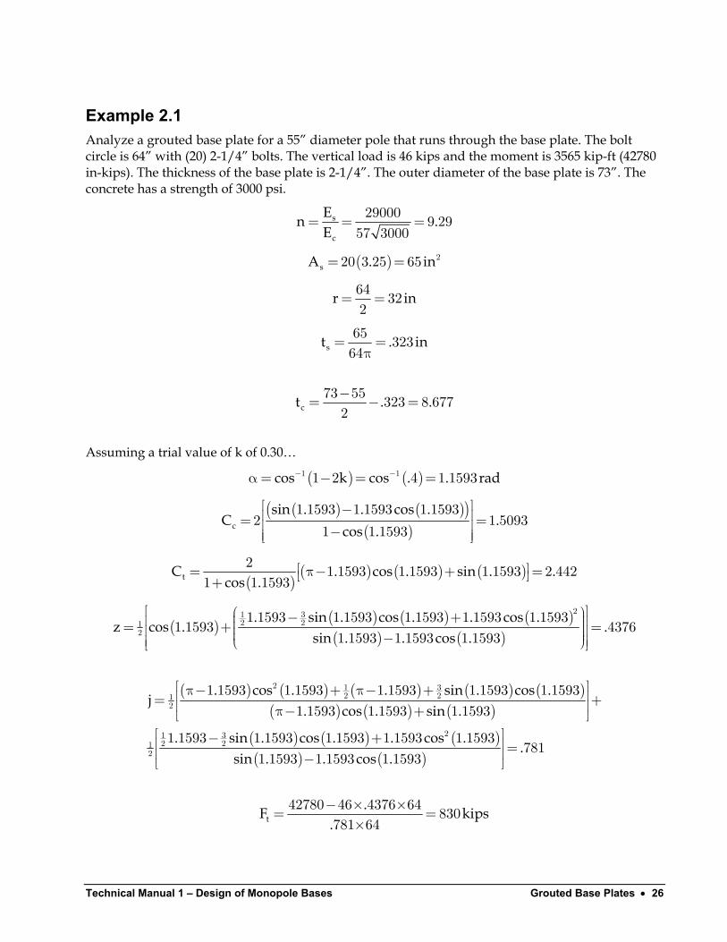
Example 2.1 Analyze a grouted base plate for a 55” diameter pole that runs through the base plate. The bolt circle is 64” with (20) 2-1/4” bolts. The vertical load is 46 kips and the moment is 3565 kip-ft (42780 in-kips). The thickness of the base plate is 2-1/4”. The outer diameter of the base plate is 73”. The concrete has a strength of 3000 psi.
s
c
En .E
= = =29000 9 2957 3000
( )sA .= = 220 3 25 65 in
r i= =64 322
n
st .= =π65 32364
in
ct .−= − =73 55 323 8 6772
.
Assuming a trial value of k of 0.30…
( ) ( )cos k cos . . rad− −α= − = =1 11 2 4 1 1593
( ) ( )( )
( )c
sin . . cos .C .
cos .
− = = −
1 1593 1 1593 1 15932 1 5093
1 1 1593
( )
( ) ( ) ( )tC . cos . sin . .cos .
= π− + = +2 1 1593 1 1593 1 1593 2 442
1 1 1593
( ) ( ) ( ) ( )( ) ( )
. sin . cos . . cos .z cos . .
sin . . cos .
− + = + = −
21 32 21
2
1 1593 1 1593 1 1593 1 1593 1 15931 1593 4376
1 1593 1 1593 1 1593
( ) ( ) ( ) ( ) ( )( ) ( ) ( )
( ) ( ) ( )( ) ( )
. cos . . sin . cos .j
. cos . sin .
. sin . cos . . cos ..
sin . . cos .
π− + π− + = + π− + − + = −
2 1 32 21
2
21 32 21
2
1 1593 1 1593 1 1593 1 1593 1 15931 1593 1 1593 1 1593
1 1593 1 1593 1 1593 1 1593 1 1593781
1 1593 1 1593 1 1593
t.F k
.− × ×= =
×42780 46 4376 64 830
781 64ips
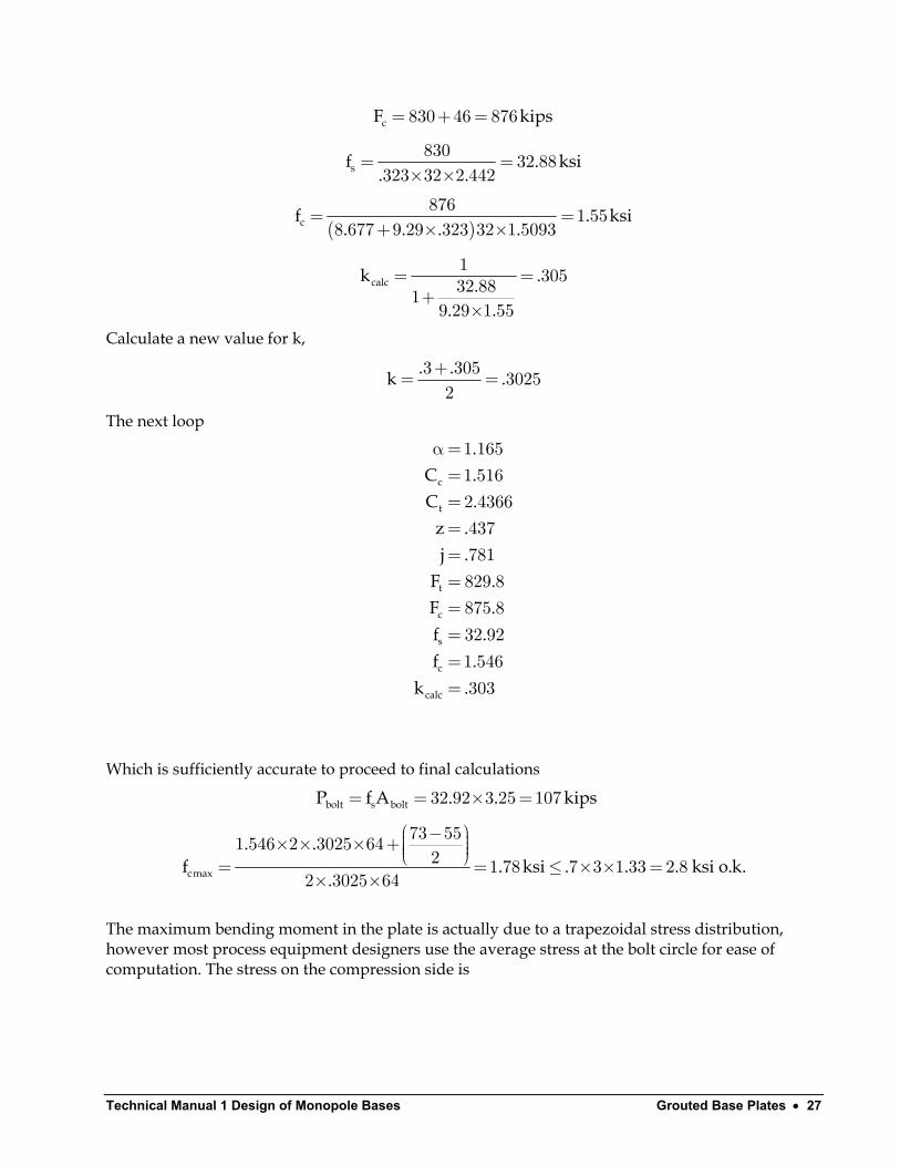
Technical Manual 1 Design of Monopole Bases Grouted Base Plates • 27
cF k= + =830 46 876 ips
sf .. .
= =× ×830 32 88
323 32 2 442ksi
( )cf .
. . . .= =
+ × ×876 1 55
8 677 9 29 323 32 1 5093ksi
calck ... .
= =+
×
1 30532 8819 29 1 55
Calculate a new value for k,
. .k .+= =3 305 30252
The next loop
c
t
t
c
s
c
calc
.C .C .
z .j .
F .F .f .f .
k .
α==========
1 1651 5162 4366437781829 8875 832 921 546303
Which is sufficiently accurate to proceed to final calculations
bolt s boltP f A . . ki= = × =32 92 3 25 107 ps
cmax
. .f . ksi .
.
− × × × + = = ≤ × × =× ×
73 551 546 2 3025 642 1 78 7 3 1 33 2 8
2 3025 64. . ksi o.k.
The maximum bending moment in the plate is actually due to a trapezoidal stress distribution, however most process equipment designers use the average stress at the bolt circle for ease of computation. The stress on the compression side is
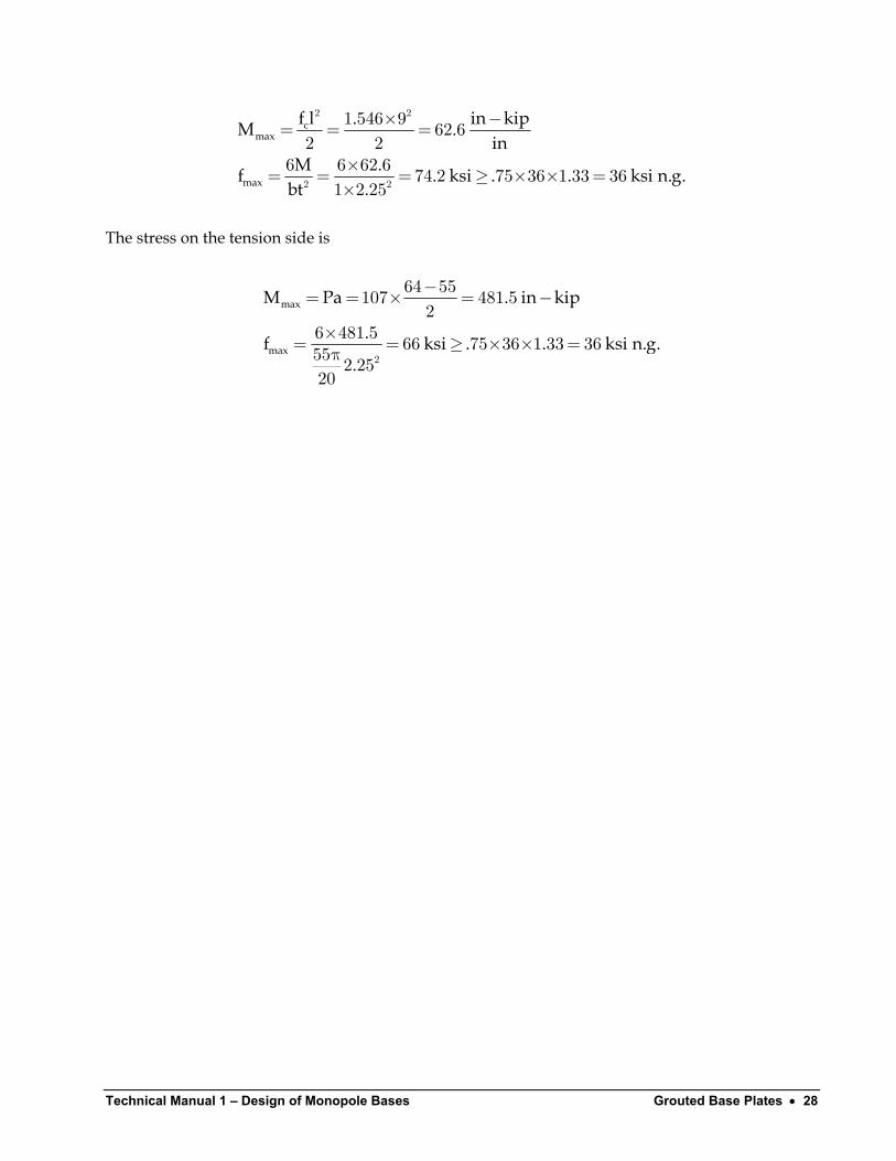
Technical Manual 1 – Design of Monopole Bases Grouted Base Plates • 28
cmax
max
in kipf l .M .in
M .f . ksi . . ksi n.g.bt .
−×= = =
×= = = ≥ × × =×
2 2
2 2
1 546 9 62 62 2
6 6 62 6 74 2 75 36 1 33 361 2 25
The stress on the tension side is
max
max
M Pa . in kip
.f ksi . . ksi n.g..
−= = × = −
×= = ≥ × × =π 2
64 55107 481 52
6 481 5 66 75 36 1 33 3655 2 2520
Technical Manual 1 Design of Monopole Bases Grouted Base Plates • 29
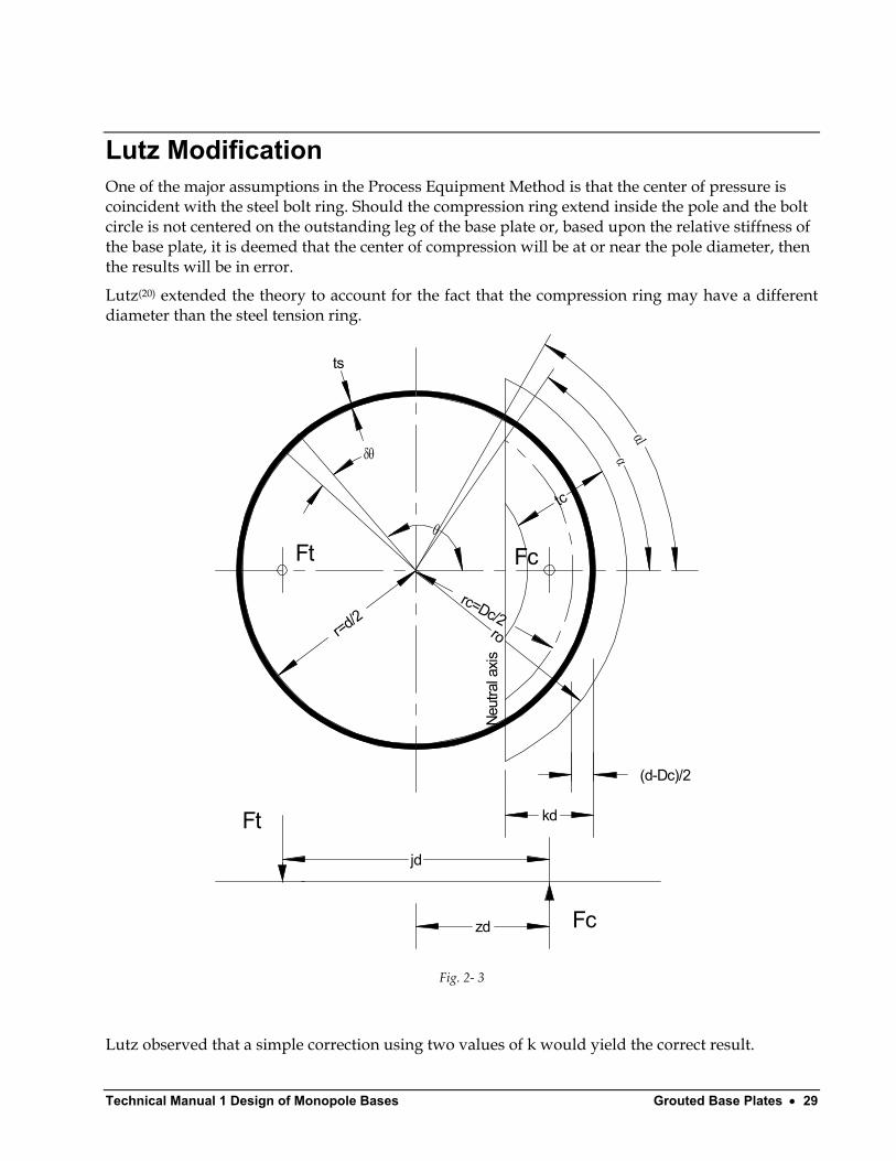
Lutz Modification One of the major assumptions in the Process Equipment Method is that the center of pressure is coincident with the steel bolt ring. Should the compression ring extend inside the pole and the bolt circle is not centered on the outstanding leg of the base plate or, based upon the relative stiffness of the base plate, it is deemed that the center of compression will be at or near the pole diameter, then the results will be in error.
Lutz(20) extended the theory to account for the fact that the compression ring may have a different diameter than the steel tension ring.
δθ
ts
θ
r=d/2
Ft Fc
Neut
ral a
xis
kd
jd
zd
Ft
Fc
tc
rc=Dc/2
(d-Dc)/2
α1α
ro
Fig. 2- 3
Lutz observed that a simple correction using two values of k would yield the correct result.

Technical Manual 1 – Design of Monopole Bases Grouted Base Plates • 30
c ct
r r rkr
−= +12
k
( ) c" jd" j d r= − +12
( )
windt
c
M PzF dj d r
−=− +12
cc
c s cc
Ffrt nt r Cr
= + c
( )
c
s
c
rr
kf
nf
+ =+
12 1
1
The peak bearing stress, at the outer edge of the base plate, with radius , is or
o ccmax c
kd r rf fkd
+ − = 22
The value is calculated using k while the values for C , z and j are then calculated using the value of . Note that when r then k and the results are identical to the Process Equipment Method.
cCt
t
k c = r kt =
Technical Manual 1 Design of Monopole Bases Grouted Base Plates • 31
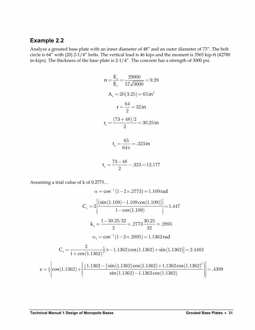
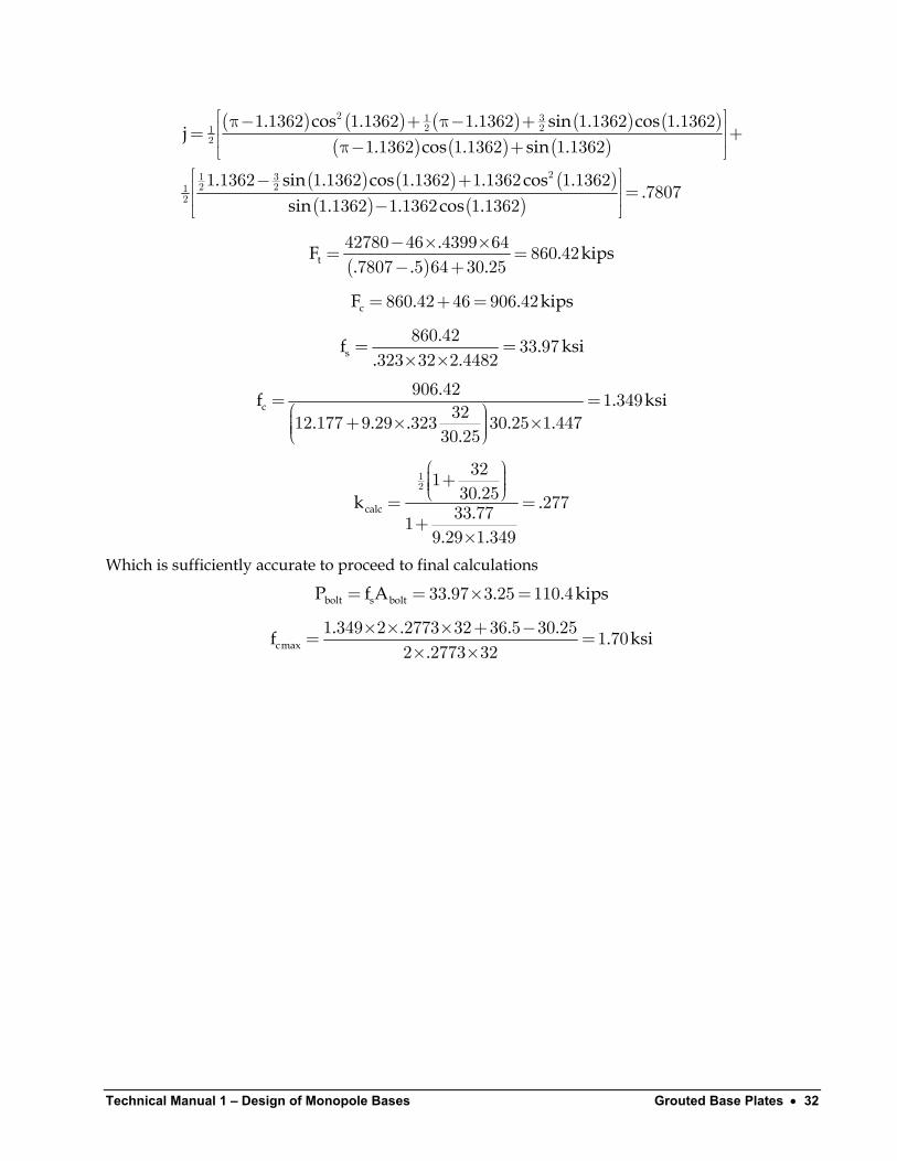
Example 2.2 Analyze a grouted base plate with an inner diameter of 48” and an outer diameter of 73”. The bolt circle is 64” with (20) 2-1/4” bolts. The vertical load is 46 kips and the moment is 3565 kip-ft (42780 in-kips). The thickness of the base plate is 2-1/4”. The concrete has a strength of 3000 psi.
s
c
En .E
= = =29000 9 2957 3000
( )sA .= = 220 3 25 65 in
r i= =64 322
n
( )
cr .+
= =73 48 2
30 252
in
st .= =π65 32364
in
ct .−= − =73 48 323 12 1772
.
Assuming a trial value of k of 0.2773…
( )cos . . rad−α= − × =1 1 2 2773 1 109
( ) ( )( )( )c
sin . . cos .C .
cos .
− = = −
1 109 1 109 1 1092 1 447
1 1 109
t. .k .−= + =1 30 25 32 30 252773 28952 32
.
( )cos . . rad−α = − × =11 1 2 2895 1 1362
( )
( ) ( ) ( )tC . cos . sin . .cos .
= π− + = +2 1 1362 1 1362 1 1362 2 4482
1 1 1362
( ) ( ) ( ) ( )( ) ( )
. sin . cos . . cos .z cos . .
sin . . cos .
− + = + = −
21 32 21
2
1 1362 1 1362 1 1362 1 1362 1 13621 1362 4399
1 1362 1 1362 1 1362
Technical Manual 1 – Design of Monopole Bases Grouted Base Plates • 32
( ) ( ) ( ) ( ) ( )( ) ( ) ( )
( ) ( ) ( )( ) ( )
. cos . . sin . cos .j
. cos . sin .
. sin . cos . . cos ..
sin . . cos .
π− + π− + = + π− + − + = −
2 1 32 21
2
21 32 21
2
1 1362 1 1362 1 1362 1 1362 1 13621 1362 1 1362 1 1362
1 1362 1 1362 1 1362 1 1362 1 13627807
1 1362 1 1362 1 1362
( )t
.F .. . .
− × ×= =− +
42780 46 4399 64 860 427807 5 64 30 25
kips
ps
cF . . ki= + =860 42 46 906 42
s.f .
. .= =
× ×860 42 33 97
323 32 2 4482ksi
c.f .
. . . . ..
= = + × ×
906 42 1 3493212 177 9 29 323 30 25 1 44730 25
ksi
calc.k ..
. .
+ = =+
×
12
32130 25 27733 771
9 29 1 349
Which is sufficiently accurate to proceed to final calculations
bolt s boltP f A . . . ki= = × =33 97 3 25 110 4 ps
cmax. . . .f .
.× × × + −= =
× ×1 349 2 2773 32 36 5 30 25 1 70
2 2773 32ksi
Technical Manual 1 Design of Monopole Bases Grouted Base Plates • 33
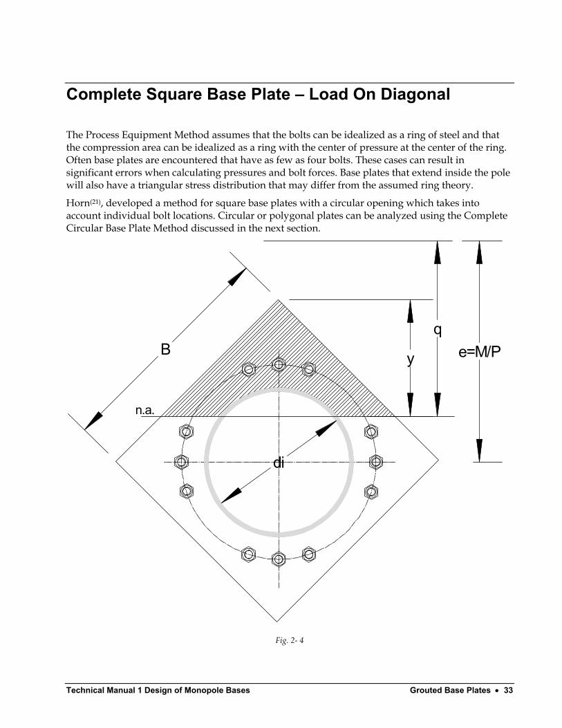
Complete Square Base Plate – Load On Diagonal
The Process Equipment Method assumes that the bolts can be idealized as a ring of steel and that the compression area can be idealized as a ring with the center of pressure at the center of the ring. Often base plates are encountered that have as few as four bolts. These cases can result in significant errors when calculating pressures and bolt forces. Base plates that extend inside the pole will also have a triangular stress distribution that may differ from the assumed ring theory.
Horn(21), developed a method for square base plates with a circular opening which takes into account individual bolt locations. Circular or polygonal plates can be analyzed using the Complete Circular Base Plate Method discussed in the next section.
Bq
y e=M/P
n.a.
di
Fig. 2- 4
Technical Manual 1 – Design of Monopole Bases Grouted Base Plates • 34
The method is valid when there is net tension on the section, a condition that occurs when
i
i
B d
ed. B B
π−> π −
4 4
22
12 64
7074
The method will make use of transformed areas of the bolts. Bolts that are in the tension zone will have their areas transformed by
bolt bA n= A
A
Bolts within the compression zone will have their areas transformed by
( )bolt bA n= −1
The method will calculate moment of inertia of the areas and the moment areas about the “e” line . The moment of inertia divided by the moment area will then be the location of the neutral axis. The process iterates on the value of q until it is determined to a sufficient degree of accuracy.
Defining
ii
c
maxc
T T
dr
y . B e
nf
PyfqA Q
=
= − +
=′
=−
27072900057
q
b
( )T c bcomp tensA A A A n A nA= + + + − +∑ ∑1 2 1
The area of the triangular wedge is defined as
y yA y×= = 2
122
Should the neutral axis (n.a.) fall below the diagonal of the plate, two wedge areas will have to be subtracted
y y . BA if y
y if y
= −= ≤=− >
2
2 2
22 2
7070 0
2 0
Should the neutral axis fall below the top of the circular opening, the area of the semi-circle must be deducted
Technical Manual 1 Design of Monopole Bases Grouted Base Plates • 35
( )i
i i
ic i i
i
l r e qy max r l, r
yrA y r y r sin ,r
−
= − += − −
π =− + − + >
0
22 2 2 1 0
0 0 02
l
bolts
The moment area is defined as
T cQ Q Q Q Q= + + +1 2
yQ A q
yQ A q
= − = −
1 1
22 2
3
3
( )c
.i
c
y , if l
r yA
= <
− −=
1
1 52 20
0 0
2
3
( )c cQ A e cy= − 1
( ) ( ) ( )j ntens j ncomp
bolts b j b jj j
Q nA e y n A e y= =
= =
= − + − −∑ ∑1 1
1
The moment of inertia of the areas is defined as
T cI I I I I= + + +1 2 bolts
y yI A q
y yI A q
= + − = + −
22
1 1
222 2
2 2
18 3
18 3
( )
( )i
i i i iic c c c c
yr siny r y r y r y rrI A
− − −π =− + − − − + −
4 1 032 2 2 2 240 0 20 0 2
1 18 2 4 4y A e y
( )boltbolts bolt j
AI A e y = + − π
∑2 2
4
T
T
IqQ
=
Technical Manual 1 – Design of Monopole Bases Grouted Base Plates • 36
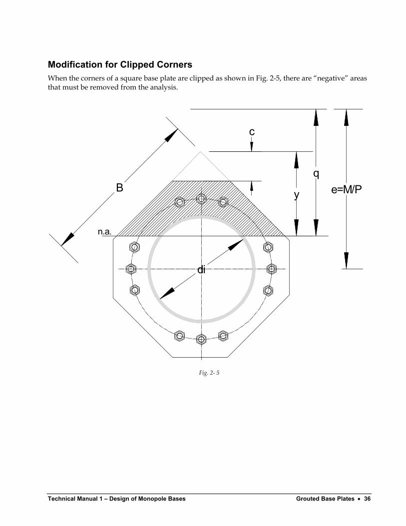
Modification for Clipped Corners When the corners of a square base plate are clipped as shown in Fig. 2-5, there are “negative” areas that must be removed from the analysis.
Bq
y e=M/P
n.a.
di
c
Fig. 2- 5
Technical Manual 1 Design of Monopole Bases Grouted Base Plates • 37
The previous equations may be used with the addition of the following terms
A ccl q y
Q A l
cI A l
=−
= − +
= = +
23
3
3 3 3
22
3 3
23
18 3
( )y if y . B c
min y . B c, c= ≤ −= − +
4 0 707
707 2
A yyl e c
Q A l
yI A l
=−
= − +
= = +
24 4
44
4 4 4
224
4 4
23
18 4
( )y if y . B
min y . B, c= ≤= −5 0 707
707
( )
( )
T c comp tens
T c
T c bolts
ct t
A yyl e
Q A l
yI A l
A A A A A A A n A nA
Q Q Q Q Q Q Q QI I I I I I I I
P y cf
qA Q
=
= +
= = +
= + + + + + + − +
= + + + + + += + + + + + +
−=
−
∑ ∑
25 5
55
5 5 5
225
5 5 5
1 2 3 4 5
1 2 3 4 5
1 2 3 4 5
3
18
1 b b
bolts
Technical Manual 1 – Design of Monopole Bases Grouted Base Plates • 38
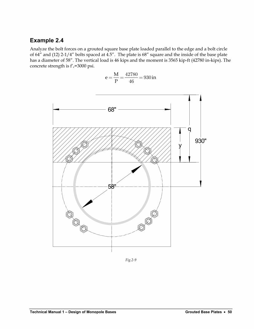
Example 2.3 Analyze the bolt forces on a grouted square base plate loaded on the diagonal and a bolt circle of 64” and (12) 2-1/4” bolts spaced at 4.5”. The plate is 68” square and the inside of the base plate has a diameter of 58”. The plate is 2.25” thick, A36 plate. The vertical load is 46 kips and the moment is 3565 kip-ft (42780 in-kips). The concrete strength is f’c=3000 psi.
Me iP
= = =42780 93046
n
68"q
y e=930"
n.a.
58"
Fig 2- 6
Technical Manual 1 Design of Monopole Bases Grouted Base Plates • 39
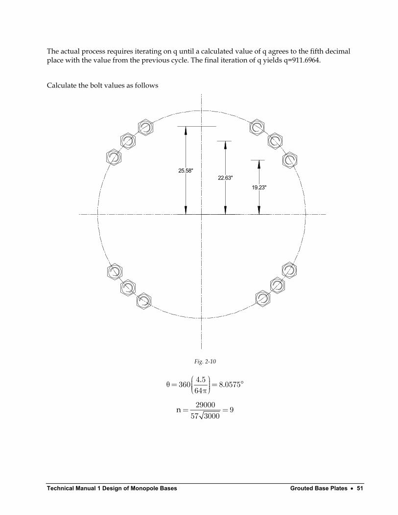
The actual process requires iterating on q until a calculated value of q agrees to the fifth decimal place with the previous cycle. The final iteration of q yields q=911.33267.
Calculate the bolt values as follows
32 31.68
4.485
4.5"
8.0575°
Fig. 2-7
. .
θ= = π4 5360 8 057564
°
n= =29000 957 3000
Technical Manual 1 – Design of Monopole Bases Grouted Base Plates • 40
Bar # ybolt n Abolt nAbolt Qbolt Ibolt 1 0 9 3.25 29.25 27202.5 252983932 0 9 3.25 29.25 27202.5 252983933 32 8 3.25 26 23348 209665584 -32 9 3.25 29.25 28138.5 270693055 4.485 9 3.25 29.25 27071.31 250549756 4.485 9 3.25 29.25 27071.31 250549757 -4.485 9 3.25 29.25 27333.69 255429888 -4.485 9 3.25 29.25 27333.69 255429889 31.684 8 3.25 26 23356.22 20981316
10 31.684 8 3.25 26 23356.22 2098131611 -31.684 9 3.25 29.25 28129.26 2705152412 -31.684 9 3.25 29.25 28129.26 27051524
Totals 341.25 317672 295894256
Calculating the plate areas
( )( )
y . .
A . .
y max , . .A
= × − + =
= =
= − × ==
21
2
2
707 68 930 911 33267 29 41
29 41 864 85
0 29 41 707 68 00
.
Calculating the deduction for the area of the hole
( )
i
i i
c
r
l . .y max r l, r .
.A . . sin−
= =
= − + == − − =
π =− + − + =−
0
22 2 2 1
58 292
29 930 911 33267 10 33
18 67
29 18 6718 67 29 18 67 29 318 612 2
.9
.
TA . . .= + + − =864 86 0 341 25 318 61 887 49
Calculating the moment areas
.Q . .
Q
= − = =
1
2
29 41864 85 911 33267 7796903
0
( )( )
.
c
.y .
.− −
= =−
1 52 2
1
2 29 18 6722 87
3 318 61
( )cQ . .=− − =−318 61 930 22 87 289020
Technical Manual 1 Design of Monopole Bases Grouted Base Plates • 41
TQ = + − + =779690 0 289020 317672 808342
Calculating the moments of inertia
. .I . .
I
= + − = =
22
1
2
29 41 29 41864 85 911 33267 70295488318 3
0
( )
( ) ( )( )
c
c
.sin. . . .I
. . . .I
− − π − =− + − −
− − + − −=−
4 132 24 2 2 2
22
18 672918 67 29 18 6729 29 18 67 29 18 67 298 2 4 4
318 61 22 87 318 61 930 22 87262180695
…
T
Tcalc
T
IIq .Q
= + − + =
= = =
702954883 0 262180695 295894256 736668444736668444 911 33267808342
Therefore, another iteration is not necessary and we can calculate final concrete and bolt stresses.
cmaxT T
pole
cpole
bc
bc
Py .f .qA Q . .
y . ..f .
. .y . .
.f .. .
×= = =− × −
= − + =×= =× −
= − + =×= =× −
46 29 41 2 95911 33267 887 49 808342
911 33267 930 29 10 33
46 10 33 1 04911 33267 887 49 808342911 33267 930 32 13 33
46 13 33 1 34911 33267 887 49 808342
ksi
ksi
ksi
( )( )
( )( )( )
( ) ( )
( )
boltbolt b
T T
bolt
bolt
compr
compr
P e y qP nA
qA Q.
P .. .
P . kips (tension).
P .. .
P . kips compression
− −=
−
− − −= ×
× −=
− −= ×
× −=−
46 930 32 911 332679 3 25
911 33267 887 49 808342148 7
46 930 32 911 332678 3 25
911 33267 887 49 80834234 8
Technical Manual 1 – Design of Monopole Bases Grouted Base Plates • 42
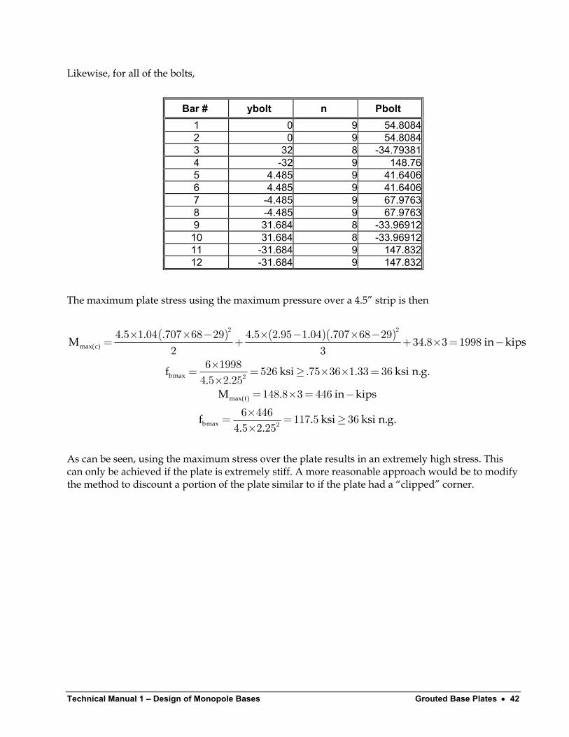
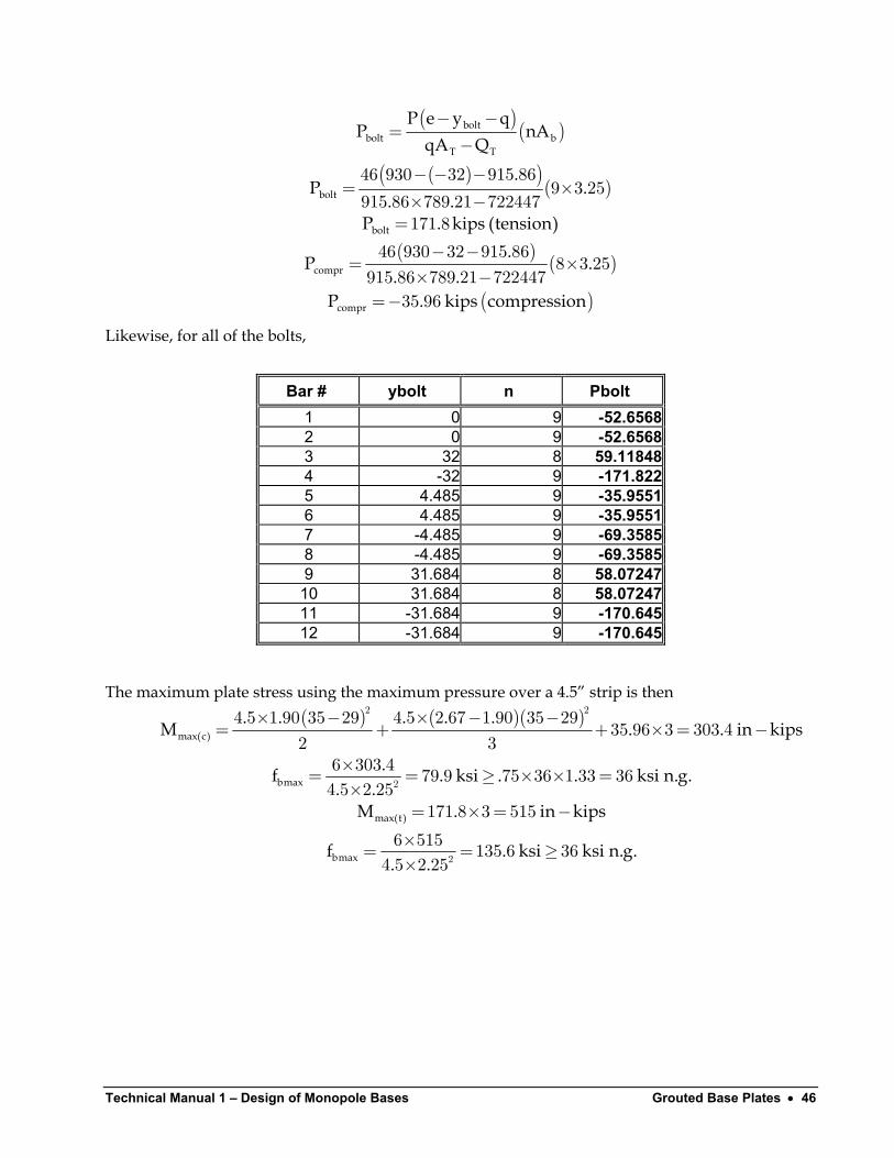
Likewise, for all of the bolts,
Bar # ybolt n Pbolt 1 0 9 54.8084 2 0 9 54.8084 3 32 8 -34.79381 4 -32 9 148.76 5 4.485 9 41.6406 6 4.485 9 41.6406 7 -4.485 9 67.9763 8 -4.485 9 67.9763 9 31.684 8 -33.96912
10 31.684 8 -33.96912 11 -31.684 9 147.832 12 -31.684 9 147.832
The maximum plate stress using the maximum pressure over a 4.5” strip is then
( ) ( )( )
max(c)
bmax
max(t)
bmax
. . . . . . .M .
f ksi . . ksi n.g.. .
M . in kips
f . ksi ksi n.g.. .
× × − × − × −= + + × = −
×= = ≥ × × =×
= × = −×= = ≥×
2 2
2
2
4 5 1 04 707 68 29 4 5 2 95 1 04 707 68 2934 8 3 1998
2 36 1998 526 75 36 1 33 364 5 2 25
148 8 3 446
6 446 117 5 364 5 2 25
in kips
As can be seen, using the maximum stress over the plate results in an extremely high stress. This can only be achieved if the plate is extremely stiff. A more reasonable approach would be to modify the method to discount a portion of the plate similar to if the plate had a “clipped” corner.
Technical Manual 1 Design of Monopole Bases Grouted Base Plates • 43
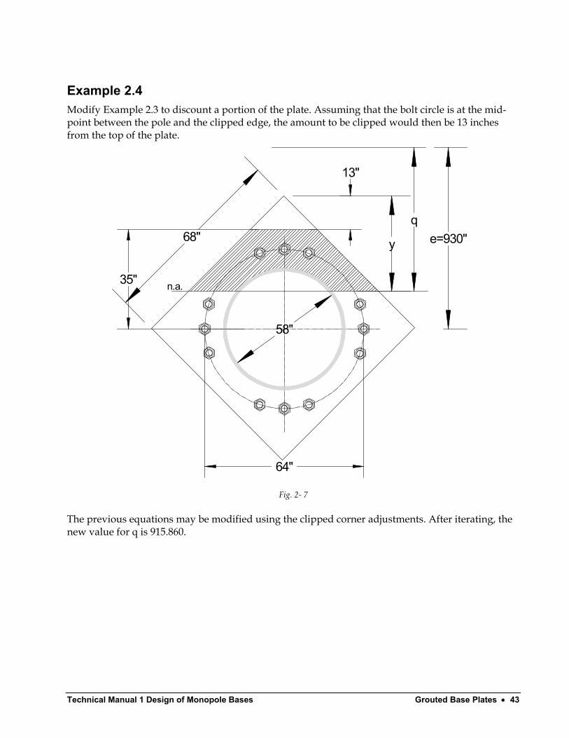
Example 2.4 Modify Example 2.3 to discount a portion of the plate. Assuming that the bolt circle is at the mid-point between the pole and the clipped edge, the amount to be clipped would then be 13 inches from the top of the plate.
68"q
y e=930"
n.a.
58"
64"
35"
13"
Fig. 2- 7
The previous equations may be modified using the clipped corner adjustments. After iterating, the new value for q is 915.860.
Technical Manual 1 – Design of Monopole Bases Grouted Base Plates • 44
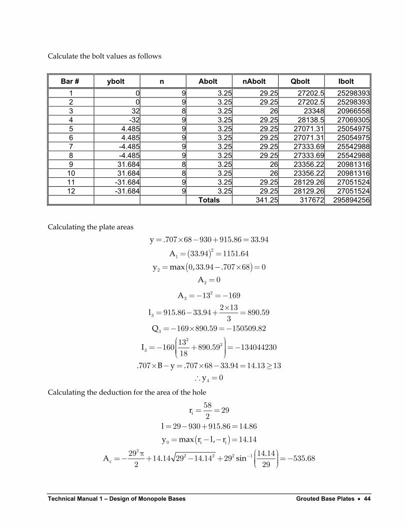
Calculate the bolt values as follows
Bar # ybolt n Abolt nAbolt Qbolt Ibolt 1 0 9 3.25 29.25 27202.5 252983932 0 9 3.25 29.25 27202.5 252983933 32 8 3.25 26 23348 209665584 -32 9 3.25 29.25 28138.5 270693055 4.485 9 3.25 29.25 27071.31 250549756 4.485 9 3.25 29.25 27071.31 250549757 -4.485 9 3.25 29.25 27333.69 255429888 -4.485 9 3.25 29.25 27333.69 255429889 31.684 8 3.25 26 23356.22 20981316
10 31.684 8 3.25 26 23356.22 2098131611 -31.684 9 3.25 29.25 28129.26 2705152412 -31.684 9 3.25 29.25 28129.26 27051524
Totals 341.25 317672 295894256
Calculating the plate areas
( )( )
y . .
A . .
y max , . .A
= × − + =
= =
= − × ==
21
2
2
707 68 930 915 86 33 94
33 94 1151 64
0 33 94 707 68 00
.
A
l . . .
Q . .
I .
. B y . . .y
=− =−×= − + =
=− × =− =− + =−
× − = × − = ≥∴ =
23
3
3
22
3
4
13 1692 13915 86 33 94 890 593
169 890 59 150509 82
13160 890 59 13404423018
707 707 68 33 94 14 13 130
Calculating the deduction for the area of the hole
( )
i
i i
c
r
l . .y max r l, r .
.A . . sin−
= =
= − + == − − =
π =− + − + =−
0
22 2 2 1
58 292
29 930 915 86 14 86
14 14
29 14 1414 14 29 14 14 29 535 682 2
.9
Technical Manual 1 Design of Monopole Bases Grouted Base Plates • 45
TA . . .= + − + − =1151 64 0 169 341 25 534 68 789 21.
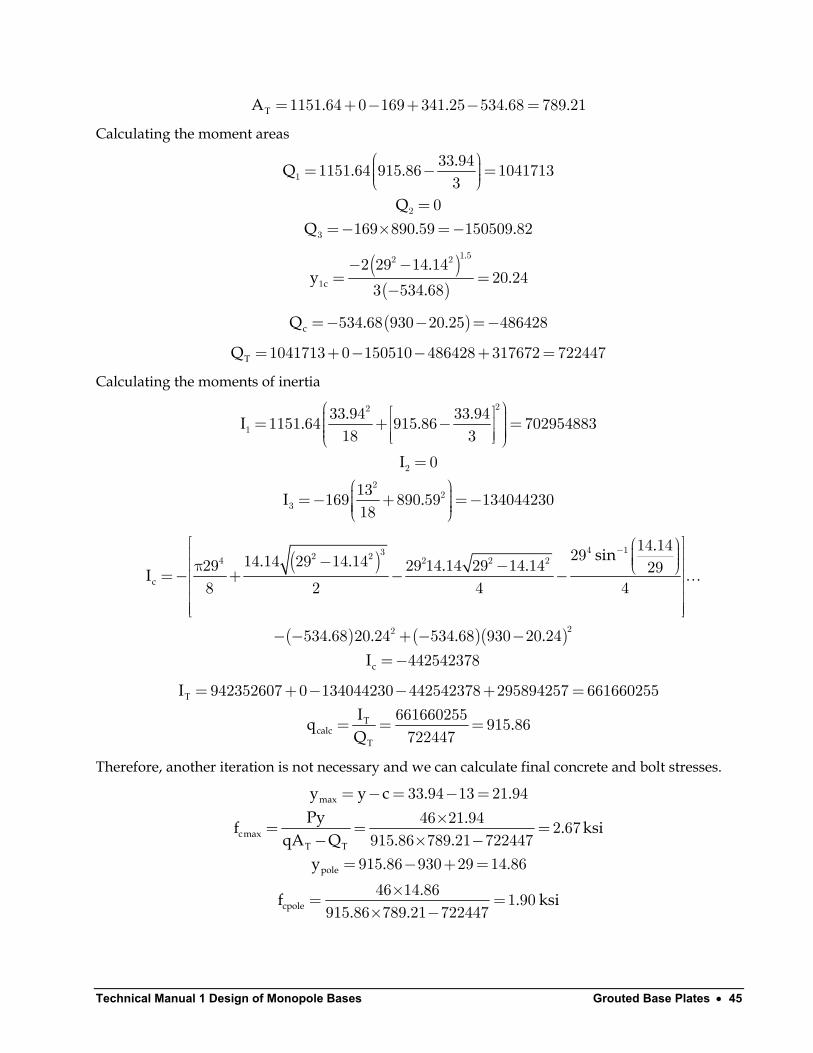
Calculating the moment areas
.Q . .
QQ .
= − = =
=− × =−
1
2
3
33 941151 64 915 86 10417133
0169 890 59 150509 82.
( )( )
.
c
.y .
.− −
= =−
1 52 2
1
2 29 14 1420 24
3 534 68
( )cQ . .=− − =−534 68 930 20 25 486428
TQ = + − − + =1041713 0 150510 486428 317672 722447
Calculating the moments of inertia
. .I . .
I
I .
= + − = =
=− + =−
22
1
2
22
3
33 94 33 941151 64 915 86 70295488318 3
0
13169 890 59 13404423018
( )
( ) ( )( )
c
c
.sin. . . .I
. . . .I
− − π − =− + − −
− − + − −=−
4 132 24 2 2 2
22
14 142914 14 29 14 1429 29 14 14 29 14 14 298 2 4 4
534 68 20 24 534 68 930 20 24442542378
…
T
Tcalc
T
IIq .Q
= + − − + =
= = =
942352607 0 134044230 442542378 295894257 661660255661660255 915 86722447
Therefore, another iteration is not necessary and we can calculate final concrete and bolt stresses.
max
cmaxT T
pole
cpole
y y c . .Py .f .
qA Q . .y . .
.f .. .
= − = − =×= = =
− × −= − + =
×= =× −
33 94 13 21 9446 21 94 2 67
915 86 789 21 722447915 86 930 29 14 86
46 14 86 1 90915 86 789 21 722447
ksi
ksi
Technical Manual 1 – Design of Monopole Bases Grouted Base Plates • 46
( )( )
( )( )( )
( ) ( )
( )
boltbolt b
T T
bolt
bolt
compr
compr
P e y qP nA
qA Q.
P .. .
P . kips (tension).
P .. .
P . kips compression
− −=
−
− − −= ×
× −=
− −= ×
× −=−
46 930 32 915 869 3 25
915 86 789 21 722447171 8
46 930 32 915 868 3 25
915 86 789 21 72244735 96
Likewise, for all of the bolts,
Bar # ybolt n Pbolt 1 0 9 -52.6568 2 0 9 -52.6568 3 32 8 59.11848 4 -32 9 -171.822 5 4.485 9 -35.9551 6 4.485 9 -35.9551 7 -4.485 9 -69.3585 8 -4.485 9 -69.3585 9 31.684 8 58.07247
10 31.684 8 58.07247 11 -31.684 9 -170.645 12 -31.684 9 -170.645
The maximum plate stress using the maximum pressure over a 4.5” strip is then
( ) ( )( )max(c)
bmax
max(t )
bmax
. . . . .M .
.f . ksi . . ksi n.g.. .
M . in kips
f . ksi ksi n.g.. .
× − × − −= + + × = −
×= = ≥ × × =×
= × = −×= = ≥×
2 2
2
2
4 5 1 90 35 29 4 5 2 67 1 90 35 2935 96 3 303 4
2 36 303 4 79 9 75 36 1 33 364 5 2 25
171 8 3 515
6 515 135 6 364 5 2 25
. in kips
Technical Manual 1 Design of Monopole Bases Grouted Base Plates • 47
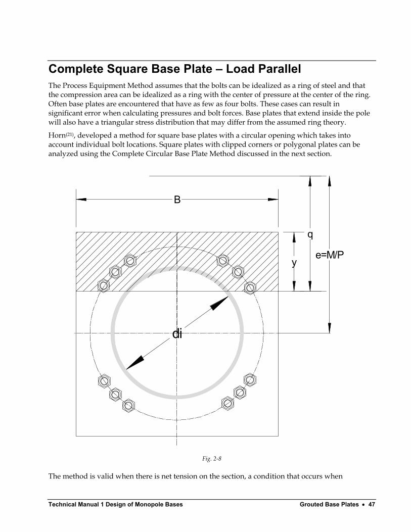
Complete Square Base Plate – Load Parallel The Process Equipment Method assumes that the bolts can be idealized as a ring of steel and that the compression area can be idealized as a ring with the center of pressure at the center of the ring. Often base plates are encountered that have as few as four bolts. These cases can result in significant error when calculating pressures and bolt forces. Base plates that extend inside the pole will also have a triangular stress distribution that may differ from the assumed ring theory.
Horn(21), developed a method for square base plates with a circular opening which takes into account individual bolt locations. Square plates with clipped corners or polygonal plates can be analyzed using the Complete Circular Base Plate Method discussed in the next section.
di
y
q
e=M/P
B
Fig. 2-8
The method is valid when there is net tension on the section, a condition that occurs when
Technical Manual 1 – Design of Monopole Bases Grouted Base Plates • 48
i
i
B d
eB dB
π−> π −
4 4
22
12 64
2 4
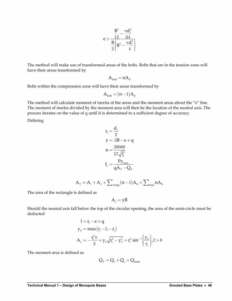
The method will make use of transformed areas of the bolts. Bolts that are in the tension zone will have their areas transformed by
bolt bA n= A
A
Bolts within the compression zone will have their areas transformed by
( )bolt bA n= −1
The method will calculate moment of inertia of the areas and the moment areas about the “e” line. The moment of inertia divided by the moment area will then be the location of the neutral axis. The process iterates on the value of q until it is determined to a sufficient degree of accuracy.
Defining
ii
c
maxc
T T
dr
y . B e q
nf
PyfqA Q
=
= − +
=′
=−
252900057
( )T c bcomp tensA A A n A nA= + + − +∑ ∑1 1 b
The area of the rectangle is defined as
A yB=1
Should the neutral axis fall below the top of the circular opening, the area of the semi-circle must be deducted
( )i
i i
ic i i
i
l r e qy max r l, r
yrA y r y r sin ,r
−
= − += − −
π =− + − + >
0
22 2 2 1 0
0 0 02
l
bolts
The moment area is defined as
T cQ Q Q Q= + +1
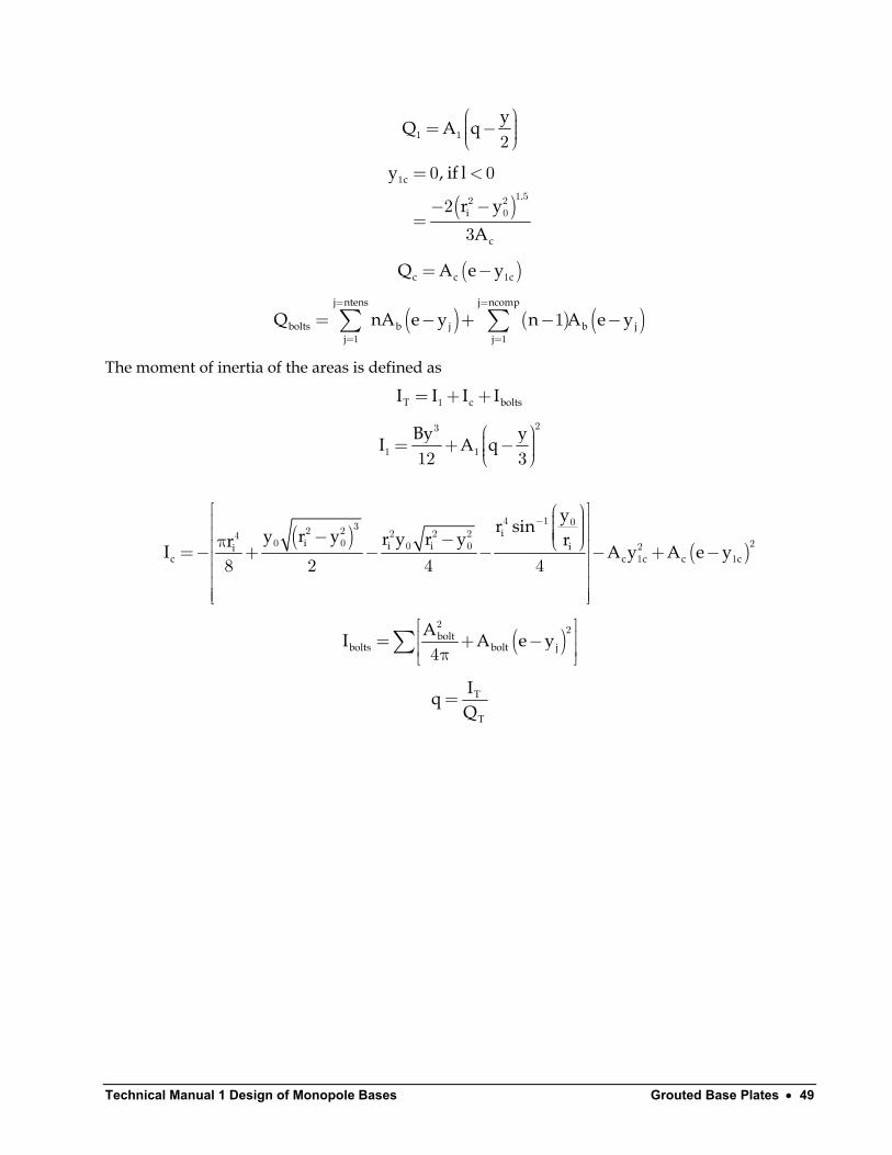
Technical Manual 1 Design of Monopole Bases Grouted Base Plates • 49
yQ A q
= − 1 1 2
( )c
.i
c
y , if l
r yA
= <
− −=
1
1 52 20
0 0
2
3
( )c cQ A e cy= − 1
( ) ( ) ( )j ntens j ncomp
bolts b j b jj j
Q nA e y n A e y= =
= =
= − + − −∑ ∑1 1
1
The moment of inertia of the areas is defined as
T cI I I I= + +1 bolts
By yI A q
= + −
23
1 112 3
( )
( )i
i i i iic c c c c
yr siny r y r y r y rrI A
− − −π =− + − − − + −
4 1 032 2 2 2 240 0 20 0 2
1 18 2 4 4y A e y
( )boltbolts bolt j
AI A e y = + − π
∑2 2
4
T
T
IqQ
=
Technical Manual 1 – Design of Monopole Bases Grouted Base Plates • 50
Example 2.4 Analyze the bolt forces on a grouted square base plate loaded parallel to the edge and a bolt circle of 64” and (12) 2-1/4” bolts spaced at 4.5”. The plate is 68” square and the inside of the base plate has a diameter of 58”. The vertical load is 46 kips and the moment is 3565 kip-ft (42780 in-kips). The concrete strength is f’c=3000 psi.
Me iP
= = =42780 93046
n
58"
y
q
930"
68"
Fig.2-9
Technical Manual 1 Design of Monopole Bases Grouted Base Plates • 51
The actual process requires iterating on q until a calculated value of q agrees to the fifth decimal place with the value from the previous cycle. The final iteration of q yields q=911.6964.
Calculate the bolt values as follows
25.58"22.63"
19.23"
Fig. 2-10
. . θ= = π4 5360 8 057564
°
n= =29000 957 3000
Technical Manual 1 – Design of Monopole Bases Grouted Base Plates • 52
Bar # ybolt n Abolt nAbolt Qbolt Ibolt 1 25.58 8 3.25 26 23514.92 212674182 25.58 8 3.25 26 23514.92 212674183 -25.58 9 3.25 29.25 27950.72 267092124 -25.58 9 3.25 29.25 27950.72 267092125 22.63 8 3.25 26 23591.62 214063826 22.63 8 3.25 26 23591.62 214063827 -22.63 9 3.25 29.25 27864.43 265445588 -22.63 9 3.25 29.25 27864.43 265445589 19.23 8 3.25 26 23680.02 21567106
10 19.23 8 3.25 26 23680.02 2156710611 -19.23 9 3.25 29.25 27764.98 2635541812 -19.23 9 3.25 29.25 27764.98 26355418
Totals 331.5 308733 287,700,186
Calculating the plate areas
y . .
A . .= × − + =
= × =1
5 68 930 911 6964 15 7068 15 70 1067 36
.
Calculating the deduction for the area of the hole
( )
i
i i
c
r
l . .y max r l, r .
.A . . sin−
= =
= − + == − − =
π =− + − + =−
0
22 2 2 1
58 292
29 930 911 6964 10 7
18 3
29 18 318 3 29 18 3 29 334 882 2
.9
.
TA . . .= + − =1067 34 331 5 334 88 1063 98
Calculating the moment areas
.Q . .
= − = 115 701067 36 911 6964 9647272
( )( )
.
c
.y .
.− −
= =−
1 52 2
1
2 29 18 322 66
3 334 88
( )cQ . .=− − =−334 88 930 22 66 303848
TQ = − + =962727 303848 308733 969612
Calculating the moments of inertia
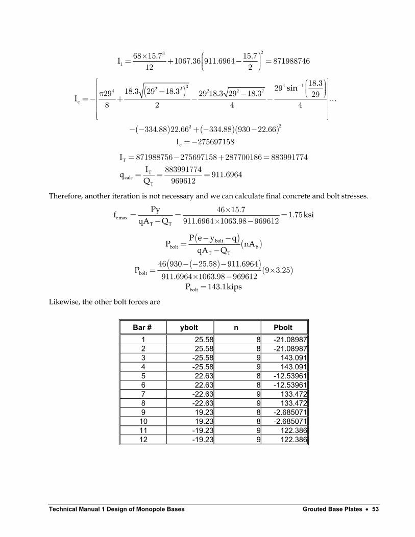
Technical Manual 1 Design of Monopole Bases Grouted Base Plates • 53
. .I . .
× = + − =
23
168 15 7 15 71067 36 911 6964 87198874612 2
( )
( ) ( )( )
c
c
.sin. . . .I
. . . .I
− − π − =− + − −
− − + − −=−
4 132 24 2 2 2
22
18 32918 3 29 18 329 29 18 3 29 18 3 298 2 4 4
334 88 22 66 334 88 930 22 66275697158
…
T
Tcalc
T
IIq .Q
= − + =
= = =
871988756 275697158 287700186 883991774883991774 911 6964969612
Therefore, another iteration is not necessary and we can calculate final concrete and bolt stresses.
cmaxT T
Py .f .qA Q . .
×= = =− × −
46 15 7 1 75911 6964 1063 98 969612
ksi
( )( )
( )( )( )
boltbolt b
T T
bolt
bolt
P e y qP nA
qA Q. .
P .. .
P . kips
− −=
−
− − −= ×
× −=
46 930 25 58 911 69649 3 25
911 6964 1063 98 969612143 1
Likewise, the other bolt forces are
Bar # ybolt n Pbolt 1 25.58 8 -21.08987 2 25.58 8 -21.08987 3 -25.58 9 143.091 4 -25.58 9 143.091 5 22.63 8 -12.53961 6 22.63 8 -12.53961 7 -22.63 9 133.472 8 -22.63 9 133.472 9 19.23 8 -2.685071
10 19.23 8 -2.685071 11 -19.23 9 122.386 12 -19.23 9 122.386
Technical Manual 1 – Design of Monopole Bases Grouted Base Plates • 54
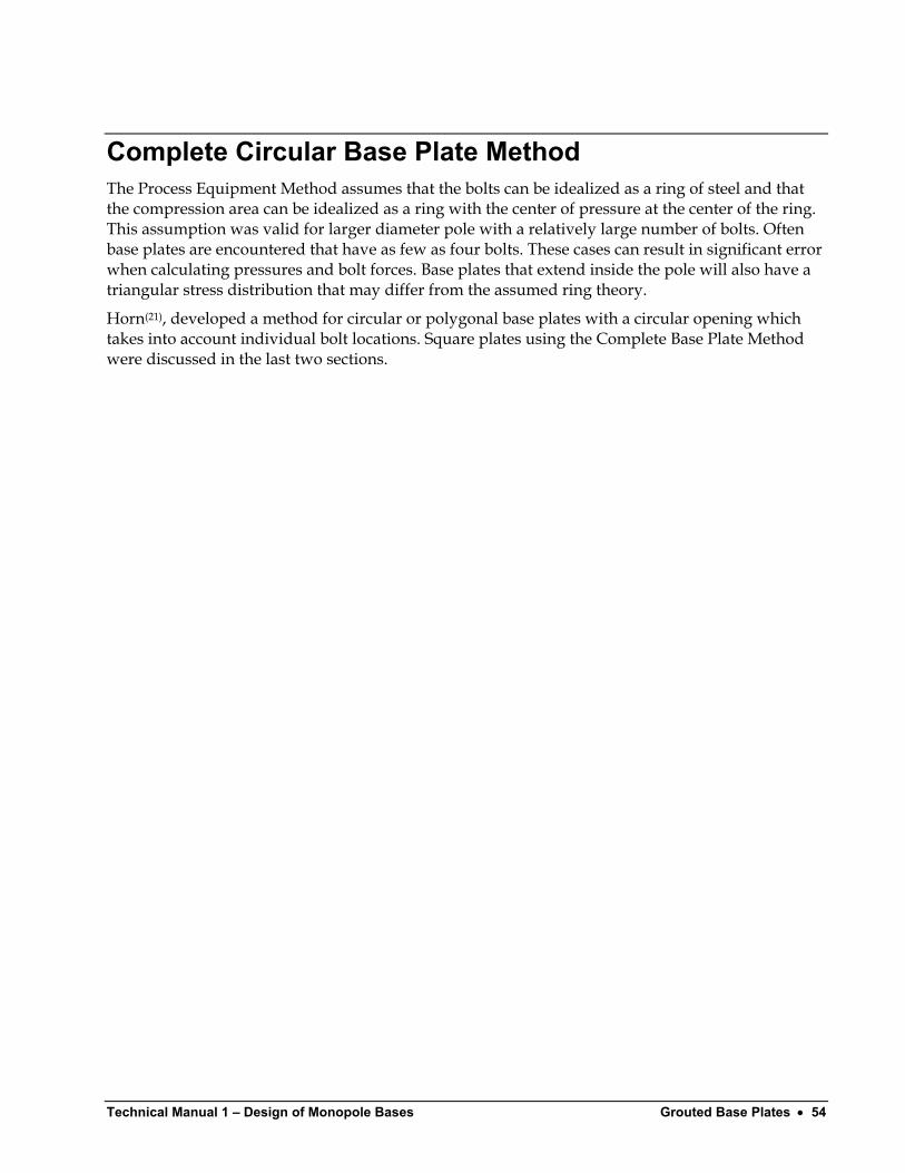
Complete Circular Base Plate Method The Process Equipment Method assumes that the bolts can be idealized as a ring of steel and that the compression area can be idealized as a ring with the center of pressure at the center of the ring. This assumption was valid for larger diameter pole with a relatively large number of bolts. Often base plates are encountered that have as few as four bolts. These cases can result in significant error when calculating pressures and bolt forces. Base plates that extend inside the pole will also have a triangular stress distribution that may differ from the assumed ring theory.
Horn(21), developed a method for circular or polygonal base plates with a circular opening which takes into account individual bolt locations. Square plates using the Complete Base Plate Method were discussed in the last two sections.
Technical Manual 1 Design of Monopole Bases Grouted Base Plates • 55
di
q
e=M/Py
B
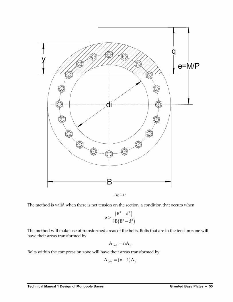
Fig.2-11
The method is valid when there is net tension on the section, a condition that occurs when
( )( )
i
i
B de
B B d−
>−
4 4
2 28
The method will make use of transformed areas of the bolts. Bolts that are in the tension zone will have their areas transformed by
bolt bA n= A
A
Bolts within the compression zone will have their areas transformed by
( )bolt bA n= −1
Technical Manual 1 – Design of Monopole Bases Grouted Base Plates • 56
The method will calculate moment of inertia of the areas and the moment areas about the “e” line. The moment of inertia divided by the moment area will then be the location of the neutral axis. The process iterates on the value of q until it is determined to a sufficient degree of accuracy.
Defining
ii
c
maxc
T T
dr
y . B e q
nf
PyfqA Q
=
= − +
=′
=−
252900057
( )T c bcomp tensA A A n A nA= + + − +∑ ∑1 1 b
The area of the outer circle is defined as
Br
l r e qy r l
yrA y r y r sinr
−
=
= − += −
π = − − −
0
0 0
22 2 2 1 0
1 0 0
2
2
Should the neutral axis fall below the top of the circular opening, the area of the semi-circle must be deducted
( )i
c i i
cic c i c i
i
l r e qy max r l, r
yrA y r y r sin ,r
−
= − += − −
π =− + − + >
22 2 2 1 0
2l
bolts
The moment area is defined as
T cQ Q Q Q= + +1
( ) .
c
r yy
A−
=1 52 2
01
2
3
( )Q A e y= −1 1 1
Technical Manual 1 Design of Monopole Bases Grouted Base Plates • 57
( )c
.i c
c
y , if l
r yA
= <
− −=
1
1 52 2
0 0
2
3
( )c cQ A e cy= − 1
( ) ( ) ( )j ntens j ncomp
bolts b j b jj j
Q nA e y n A e y= =
= =
= − + − −∑ ∑1 1
1
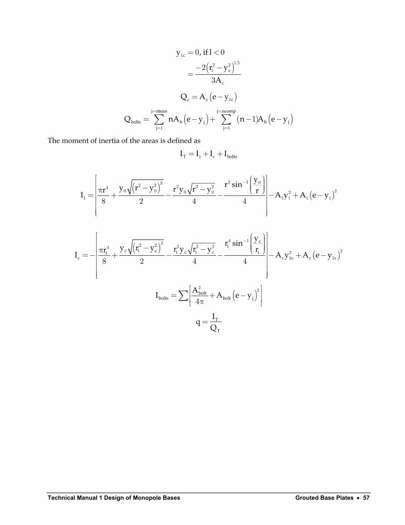
The moment of inertia of the areas is defined as
T cI I I I= + +1 bolts
( )
( )yr siny r y r y r yr rI A y A e y
− − − π = + − − − + −
2 1 032 2 2 2 240 0 20 0 2
1 1 1 1 18 2 4 4
( )
( )c
ic i c i c i c ii
c c c c c
yr siny r y r y r y rrI A
− − −π =− + − − − + −
4 132 2 2 2 2422
1 18 2 4 4y A e y
( )boltbolts bolt j
AI A e y = + − π
∑2 2
4
T
T
IqQ
=
Technical Manual 1 – Design of Monopole Bases Grouted Base Plates • 58
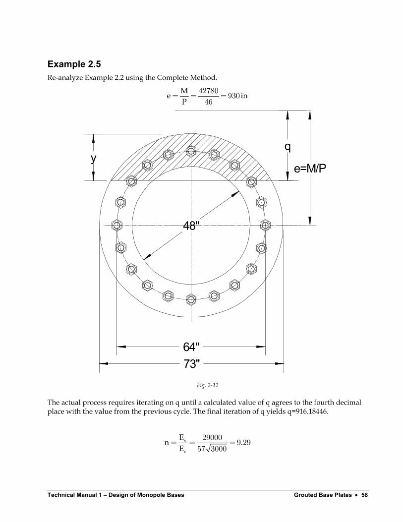
Example 2.5 Re-analyze Example 2.2 using the Complete Method.
Me iP
= = =42780 93046
n
48"
q
e=M/Py
73"64"
Fig. 2-12
The actual process requires iterating on q until a calculated value of q agrees to the fourth decimal place with the value from the previous cycle. The final iteration of q yields q=916.18446.
s
c
En .E
= = =29000 9 2957 3000
Technical Manual 1 Design of Monopole Bases Grouted Base Plates • 59
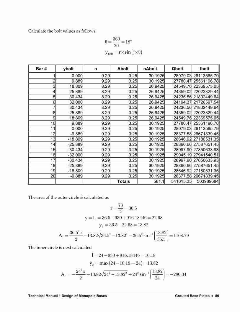
Calculate the bolt values as follows
( )bolty r sin j
θ= = °
= × ×θ
360 1820
Bar # ybolt n Abolt nAbolt Qbolt Ibolt 1 0.000 9.29 3.25 30.1925 28079.03 26113565.792 9.889 9.29 3.25 30.1925 27780.47 25561196.783 18.809 8.29 3.25 26.9425 24549.76 22369575.054 25.889 8.29 3.25 26.9425 24359.02 22023329.445 30.434 8.29 3.25 26.9425 24236.56 21802449.646 32.000 8.29 3.25 26.9425 24194.37 21726597.547 30.434 8.29 3.25 26.9425 24236.56 21802449.648 25.889 8.29 3.25 26.9425 24359.02 22023329.449 18.809 8.29 3.25 26.9425 24549.76 22369575.05
10 9.889 9.29 3.25 30.1925 27780.47 25561196.7811 0.000 9.29 3.25 30.1925 28079.03 26113565.7912 -9.889 9.29 3.25 30.1925 28377.58 26671839.4513 -18.809 9.29 3.25 30.1925 28646.92 27180531.3514 -25.889 9.29 3.25 30.1925 28860.66 27587651.4515 -30.434 9.29 3.25 30.1925 28997.90 27850633.9316 -32.000 9.29 3.25 30.1925 29045.19 27941540.5117 -30.434 9.29 3.25 30.1925 28997.90 27850633.9318 -25.889 9.29 3.25 30.1925 28860.66 27587651.4519 -18.809 9.29 3.25 30.1925 28646.92 27180531.3520 -9.889 9.29 3.25 30.1925 28377.58 26671839.45
Totals 581.1 541015.35 503989684
The area of the outer circle is calculated as
r .
y l . . .y . . .
. .A . . . . sin.
−
= =
= = − + == − =
π = − − − =
0
0
22 2 2 1
1
73 36 52
36 5 930 916 18446 22 6836 5 22 68 13 82
36 5 13 8213 82 36 5 13 82 36 5 1108 792 3
.6 5
The inner circle is next calculated
( )c
c
l . .y max . , .
.A . . sin−
= − + == − − =
π =− + − + =−
22 2 2 1
24 930 916 18446 10 18
24 10 18 24 13 82
24 13 8213 82 24 13 82 24 280 342 2
.4
Technical Manual 1 – Design of Monopole Bases Grouted Base Plates • 60
TA . . .= + − =1108 79 581 1 280 34 1409 55.
Calculating the moment areas
( )( )
.. .
y ..
−= =
1 52 2
1
2 36 5 13 8223 18
3 1108 79
( )Q . .= − =1 1108 79 930 23 18 1005464
( )( )
.
c
.y .
.− −
= =−
1 52 22 24 13 8217 97
3 280 34
( )cQ . .=− − =−280 34 930 17 97 255674
TQ = + − =1005464 541015 255674 1290806
Calculating the moments of inertia
( )
( ) ( )( )
.. sin. . .. . . . . .I
. . . .I
− − π − = + − −
− + −=
4 132 24 2 2 2
1
22
1
13 8236 513 82 36 5 13 8236 5 36 5 13 82 36 5 13 82 36 58 2 4 4
1108 79 23 18 1108 79 930 23 18911810020
…
( )
( ) ( )( )
c
c
.sin. . . .I
. . . .I
− − π − =− + − −
− − + − −=−
4 132 24 2 2 2
22
13 822413 82 24 13 8224 24 13 82 24 13 82 248 2 4 4
280 34 17 97 280 34 930 17 97233183299
…
T
Tcalc
T
IIq .Q
= + − =
= = =
911810020 503898968 233183299 11826164051182616405 916 184461290806
Therefore, another iteration is not necessary and we can calculate final concrete and bolt stresses.
cmaxT T
Py .f .qA Q . .
×= = =− × −
46 22 68 1 73916 18446 1409 55 1290806
ksi
bc
bct t
y . .
Py .f .qA Q . .
= − + =
×= = =− × −
64 930 916 18446 18 182
46 18 18 1 39916 18446 1409 55 1290806
Technical Manual 1 Design of Monopole Bases Grouted Base Plates • 61
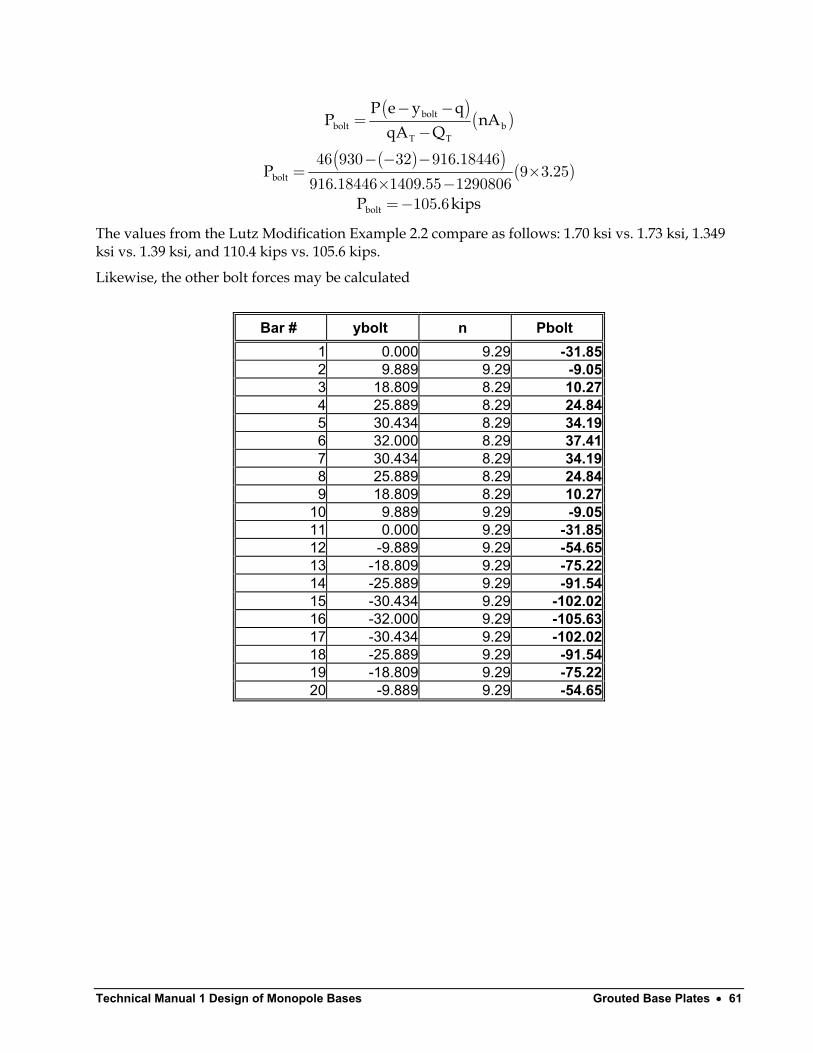
( )( )
( )( ) ( )
boltbolt b
T T
bolt
bolt
P e y qP nA
qA Q.
P .. .
P . kips
− −=
−
− − −= ×
× −=−
46 930 32 916 184469 3 25
916 18446 1409 55 1290806105 6
The values from the Lutz Modification Example 2.2 compare as follows: 1.70 ksi vs. 1.73 ksi, 1.349 ksi vs. 1.39 ksi, and 110.4 kips vs. 105.6 kips.
Likewise, the other bolt forces may be calculated
Bar # ybolt n Pbolt 1 0.000 9.29 -31.85 2 9.889 9.29 -9.05 3 18.809 8.29 10.27 4 25.889 8.29 24.84 5 30.434 8.29 34.19 6 32.000 8.29 37.41 7 30.434 8.29 34.19 8 25.889 8.29 24.84 9 18.809 8.29 10.27
10 9.889 9.29 -9.05 11 0.000 9.29 -31.85 12 -9.889 9.29 -54.65 13 -18.809 9.29 -75.22 14 -25.889 9.29 -91.54 15 -30.434 9.29 -102.02 16 -32.000 9.29 -105.63 17 -30.434 9.29 -102.02 18 -25.889 9.29 -91.54 19 -18.809 9.29 -75.22 20 -9.889 9.29 -54.65
Technical Manual 1 – Design of Monopole Bases Grouted Base Plates • 62
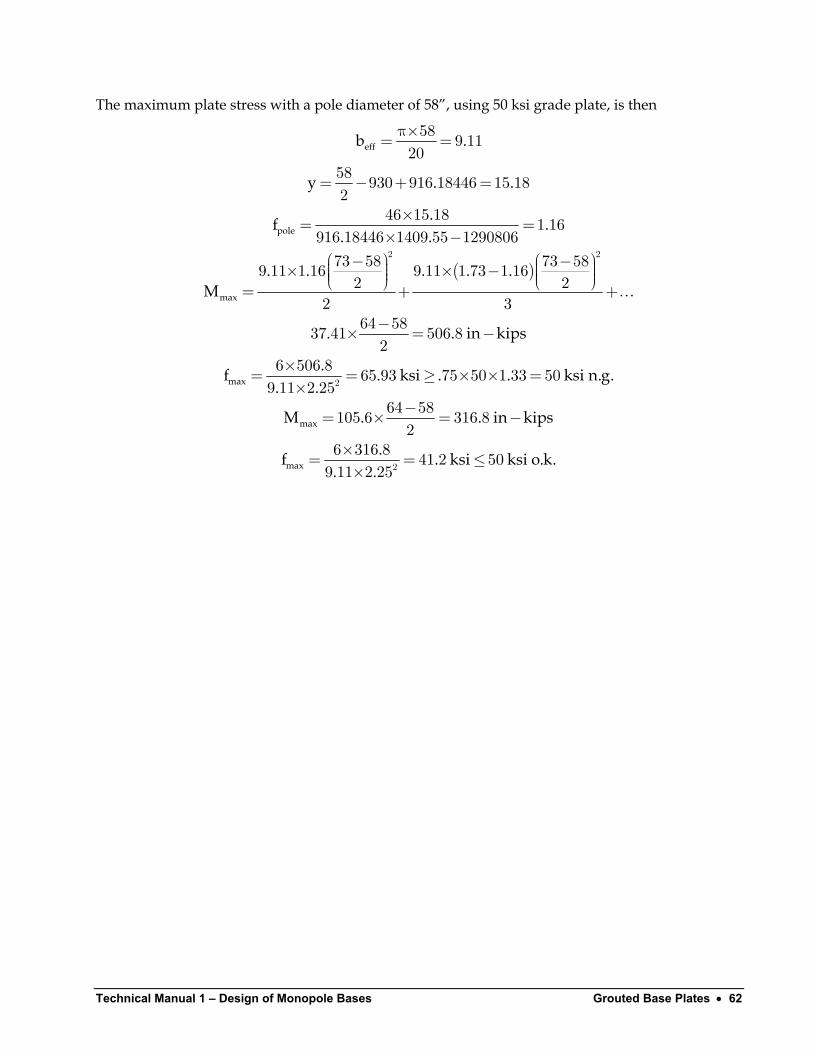
The maximum plate stress with a pole diameter of 58”, using 50 ksi grade plate, is then
( )
eff
pole
max
max
b .
y . .
.f .. .
. . . . .M
. . in kips
.f. .
π×= =
= − + =
×= =× −
− − × × − = +
−× = −
×= =×
2 2
2
58 9 1120
58 930 916 18446 15 182
46 15 18 1 16916 18446 1409 55 129080673 58 73 589 11 1 16 9 11 1 73 1 162 2
2 364 5837 41 506 82
6 506 89 11 2 25
…+
max
max
. ksi . . ksi n.g.
M . . in kips
.f . ksi ksi o.k.. .
≥ × × =
−= × = −
×= = ≤× 2
65 93 75 50 1 33 50
64 58105 6 316 82
6 316 8 41 2 509 11 2 25
Technical Manual 1 Design of Monopole Bases Ungrouted Base Plates • 63
Ungrouted Base Plates
Determining Bolt Forces Most monopoles built today do not have grouted base plates. Grouting of the plate can lead to corrosion problems if means are not provided to allow for drainage of condensation that can develop within the pole. Once grouted, the pole can no longer be adjusted for any out-of-plumb condition since the leveling nuts will be encased within the grout. Some manufacturers have specific warranty disclaimers if the pole is grouted.
The determination of bolt forces in ungrouted base plates is straightforward. The bolt group should be symmetrical about both axes and the bolts should be the same size. Square base plates usually have the bolt clustered in four groups located along the diagonals of the plate.
The maximum bolt force is determined by
maxmax
MyPFn I
= +
Where n is the number of bolts and ymax and I are calculated as illustrated in the following examples.
Technical Manual 1 – Design of Monopole Bases Ungrouted Base Plates • 64
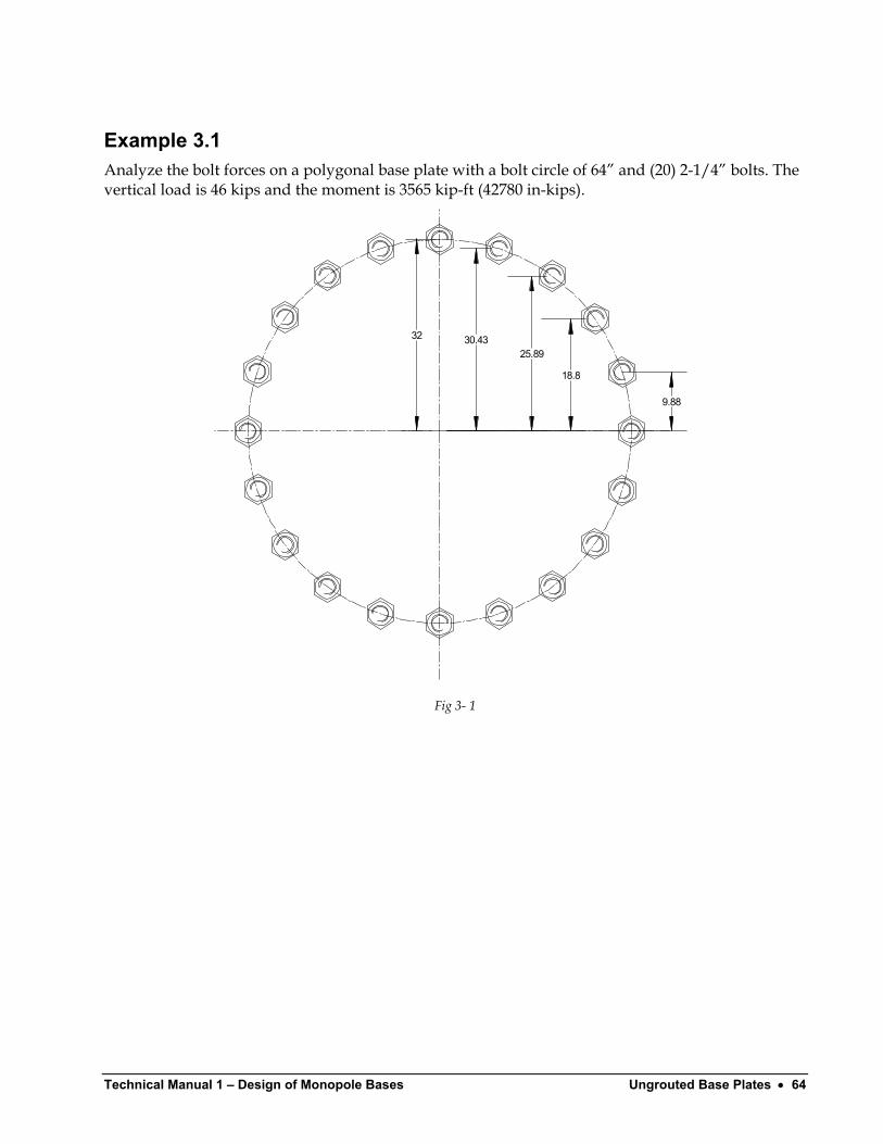
Example 3.1 Analyze the bolt forces on a polygonal base plate with a bolt circle of 64” and (20) 2-1/4” bolts. The vertical load is 46 kips and the moment is 3565 kip-ft (42780 in-kips).
32 30.4325.89
18.8
9.88
Fig 3- 1
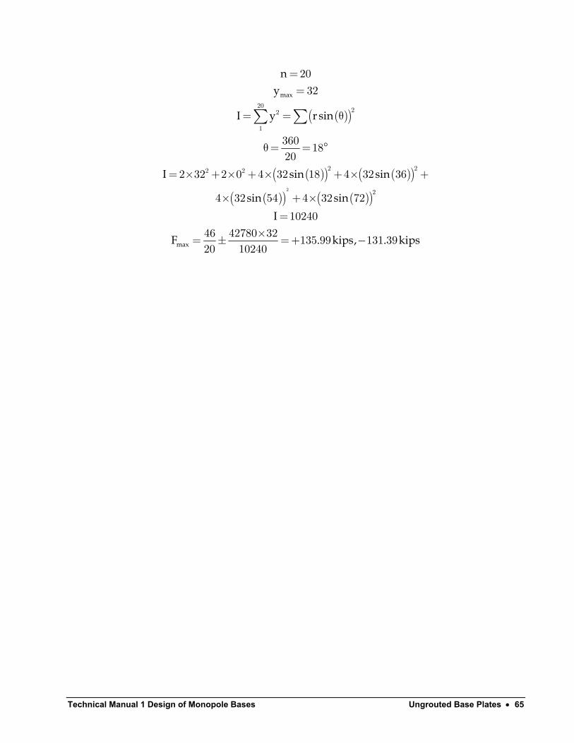
Technical Manual 1 Design of Monopole Bases Ungrouted Base Plates • 65
( )( )
( )( ) ( )( )( )( ) ( )( )
max
max
ny
I y r sin
I sin
sin sinI
F . kips, . kips
==
= = θ
θ= = °
= × + × + × + × +
× + ×=
×= ± =+ −
∑ ∑
2
2022
1
2 22 2
2
2032
360 1820
2 32 2 0 4 32 18 4 32 36
4 32 54 4 32 72
1024046 42780 32 135 99 131 3920 10240
sin
Technical Manual 1 – Design of Monopole Bases Ungrouted Base Plates • 66
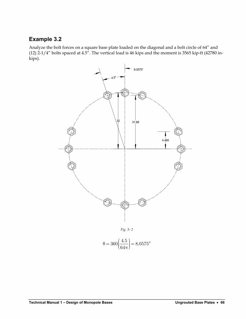
Example 3.2 Analyze the bolt forces on a square base plate loaded on the diagonal and a bolt circle of 64” and (12) 2-1/4” bolts spaced at 4.5”. The vertical load is 46 kips and the moment is 3565 kip-ft (42780 in-kips).
32 31.68
4.485
4.5"
8.0575°
Fig. 3- 2
. .
θ= = π4 5360 8 057564
°

Technical Manual 1 Design of Monopole Bases Ungrouted Base Plates • 67
( )( )
( )( ) ( )( )
max
max
ny
I y r sin
I sin . sin .I
F . kips, . kips
==
= = θ
= × + × + × + ×=
×= ± =+ −
∑ ∑12
22
12 22 2
1232
2 32 2 0 4 32 8 0575 4 32 81 9425
614446 42780 32 226 6 219 012 6144
Technical Manual 1 – Design of Monopole Bases Ungrouted Base Plates • 68
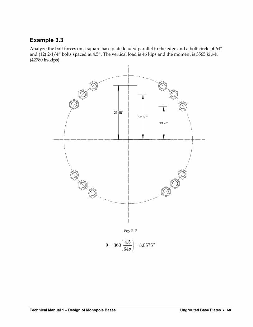
Example 3.3 Analyze the bolt forces on a square base plate loaded parallel to the edge and a bolt circle of 64” and (12) 2-1/4” bolts spaced at 4.5”. The vertical load is 46 kips and the moment is 3565 kip-ft (42780 in-kips).
25.58"22.63"
19.23"
Fig. 3- 3
. . θ= = π4 5360 8 057564
°
Technical Manual 1 Design of Monopole Bases Ungrouted Base Plates • 69
( )( )
( )( ) ( )( ) ( )( )
max
max
ny .
I y r sin
I sin . sin sin .I.F kips, . kips
==
= = θ
= × − + × + × +=
×= ± =+ −
∑ ∑12
22
12 2
1225 58
4 32 45 8 0575 4 32 45 4 32 45 8 0575
614446 42780 25 58 182 174 312 6144
2
As can be seen from these two examples, the maximum bolt force is always determined from the loading along the diagonal for a square base plate.
Determining Bolt Shear Shearing stresses in the pole are a maximum at the equator of the pole. A flexible base plate will therefore have shearing forces distributed primarily to the two side regions at the equator. The shear resisted by the bolts will then be
vVFn
= 2
When the base plate is solid (without a central hole), the plate would be sufficiently rigid to equally distribute the shear to all of the bolts.
vVFn
=
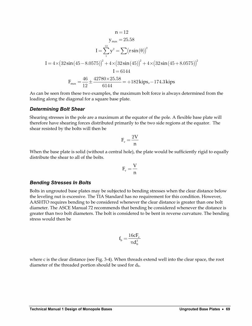
Bending Stresses In Bolts Bolts in ungrouted base plates may be subjected to bending stresses when the clear distance below the leveling nut is excessive. The TIA Standard has no requirement for this condition. However, AASHTO requires bending to be considered whenever the clear distance is greater than one bolt diameter. The ASCE Manual 72 recommends that bending be considered whenever the distance is greater than two bolt diameters. The bolt is considered to be bent in reverse curvature. The bending stress would then be
vb
b
cFfd
=π 3
16
where c is the clear distance (see Fig. 3-4). When threads extend well into the clear space, the root diameter of the threaded portion should be used for db.
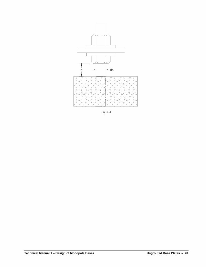
Technical Manual 1 – Design of Monopole Bases Ungrouted Base Plates • 70
c db
Fig 3- 4
Technical Manual 1 Design of Monopole Bases Determining Plate Stresses • 71
Determining Plate Stresses
Introduction The methods of determining bolt forces and concrete stresses presented in the previous chapters are commonly used by all designers. The methods for determining the base plate bending stresses, however, are not so uniformly accepted.
Effective Width Based Upon Plate Theory Traditionally, most methods have used the peak bolt force or maximum concrete stress in determining a cantilever moment on an effective width of plate at the pole to determine the plate stress by simple beam theory. The moment would be equal to the
M F d= ×where F is the force and d is the distance from the force to the face of the pole. The stress in the plate would then be
eff
MfB t
= 2
6
To determine if this is realistic, consider a circular ring, guided at the pole but free to displace vertically, and simply supported continuously at the anchor bolt circle. Roarke(25) Table 24.1b states that the maximum moment in the ring will be
( )
o o
o
LM waC
bCa
r raL lna r a
=
= +υ+ −υ +υ −υ = + −
9
8
2
8
2
9
1 1 12
1 1 12 4
where “a” is the radius of the outside of the ring and “b” is the radius of the inside of the ring (outside radius of the pole). Poisson’s ratio can be taken as 0.30 for steel. The unit load, “w” is taken
Technical Manual 1 – Design of Monopole Bases Determining Plate Stresses • 72
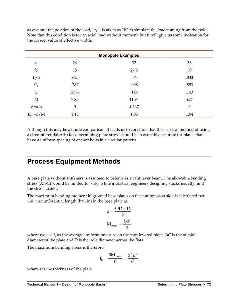
as one and the position of the load, “ro”, is taken as “b” to simulate the load coming from the pole. Note that this condition is for an axial load without moment, but it will give us some indication for the correct value of effective width.
Monopole Examples
a 24 32 36
b 15 27.5 30
b/a .625 .86 .833
C8 .787 .908 .893
L9 .2576 .124 .143
M 7.85 11.94 5.77
d=a-b 9 4.367 6
Beff=d/M 1.15 1.03 1.04
Although this may be a crude comparison, it leads us to conclude that the classical method of using a circumferential strip for determining plate stress should be reasonably accurate for plates that have a uniform spacing of anchor bolts in a circular pattern.
Process Equipment Methods
A base plate without stiffeners is assumed to behave as a cantilever beam. The allowable bending stress (AISC) would be limited to .75Fy, while industrial engineers designing stacks usually limit the stress to .6Fy.
The maximum bending moment in grouted base plates on the compression side is calculated per unit circumferential length (b=1 in) in the base plate as
c
press
OD Dd
f dM
−=
=2
2
2
where we use fc as the average uniform pressure on the cantilevered plate, OC is the outside diameter of the plate and D is the pole diameter across the flats.
The maximum bending stress is therefore
press cb
M f dft t
= =2
2 2
6 3
where t is the thickness of the plate.
Technical Manual 1 Design of Monopole Bases Determining Plate Stresses • 73
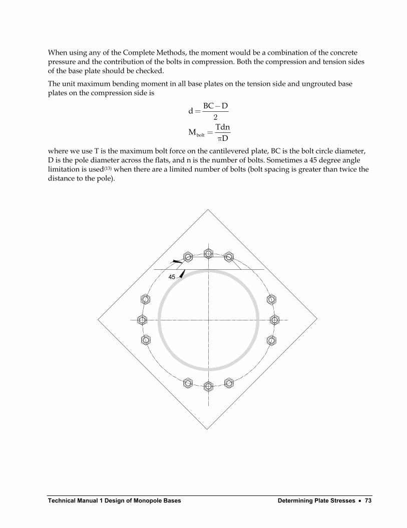
When using any of the Complete Methods, the moment would be a combination of the concrete pressure and the contribution of the bolts in compression. Both the compression and tension sides of the base plate should be checked.
The unit maximum bending moment in all base plates on the tension side and ungrouted base plates on the compression side is
bolt
BC Dd
TdnMD
−=
=π
2
where we use T is the maximum bolt force on the cantilevered plate, BC is the bolt circle diameter, D is the pole diameter across the flats, and n is the number of bolts. Sometimes a 45 degree angle limitation is used(13) when there are a limited number of bolts (bolt spacing is greater than twice the distance to the pole).
45
Technical Manual 1 – Design of Monopole Bases Determining Plate Stresses • 74
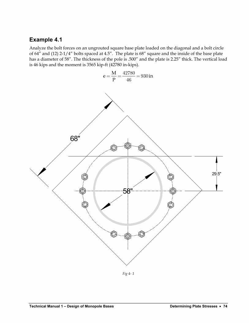
Example 4.1 Analyze the bolt forces on an ungrouted square base plate loaded on the diagonal and a bolt circle of 64” and (12) 2-1/4” bolts spaced at 4.5”. The plate is 68” square and the inside of the base plate has a diameter of 58”. The thickness of the pole is .500” and the plate is 2.25” thick. The vertical load is 46 kips and the moment is 3565 kip-ft (42780 in-kips).
Me iP
= = =42780 93046
n
68"
58"
29.5"
Fig 4- 1
Technical Manual 1 Design of Monopole Bases Determining Plate Stresses • 75
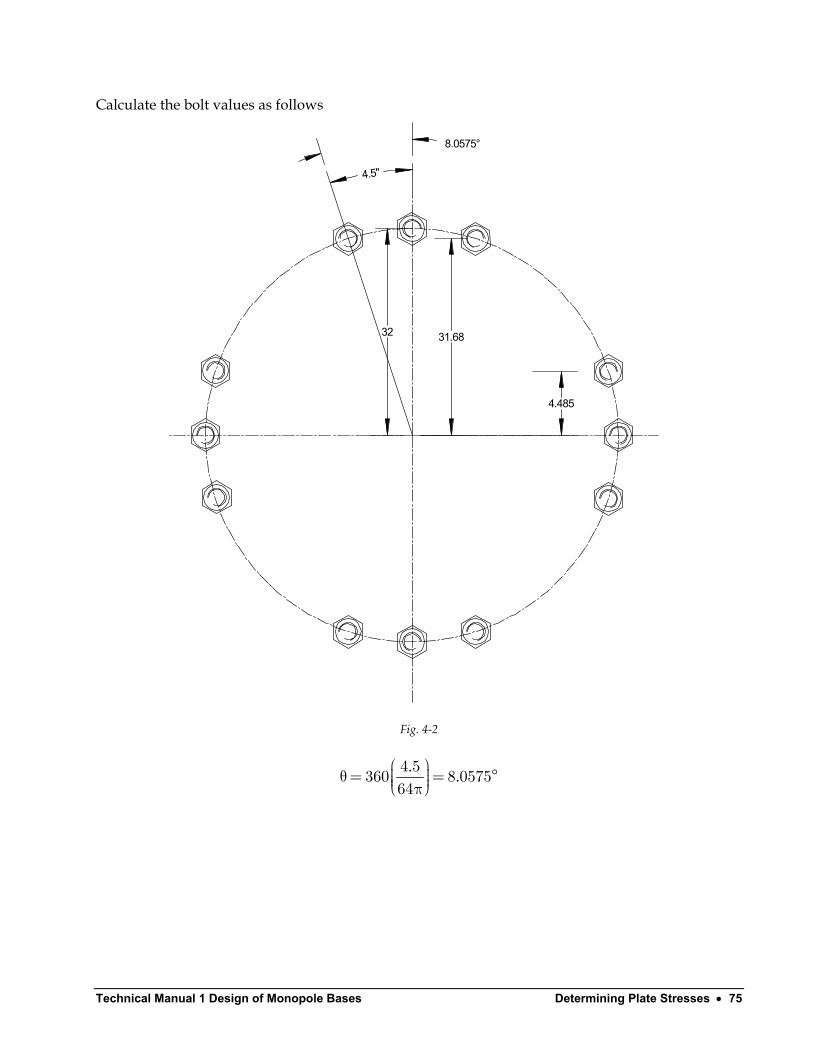
Calculate the bolt values as follows
32 31.68
4.485
4.5"
8.0575°
Fig. 4-2
. .
θ= = π4 5360 8 057564
°
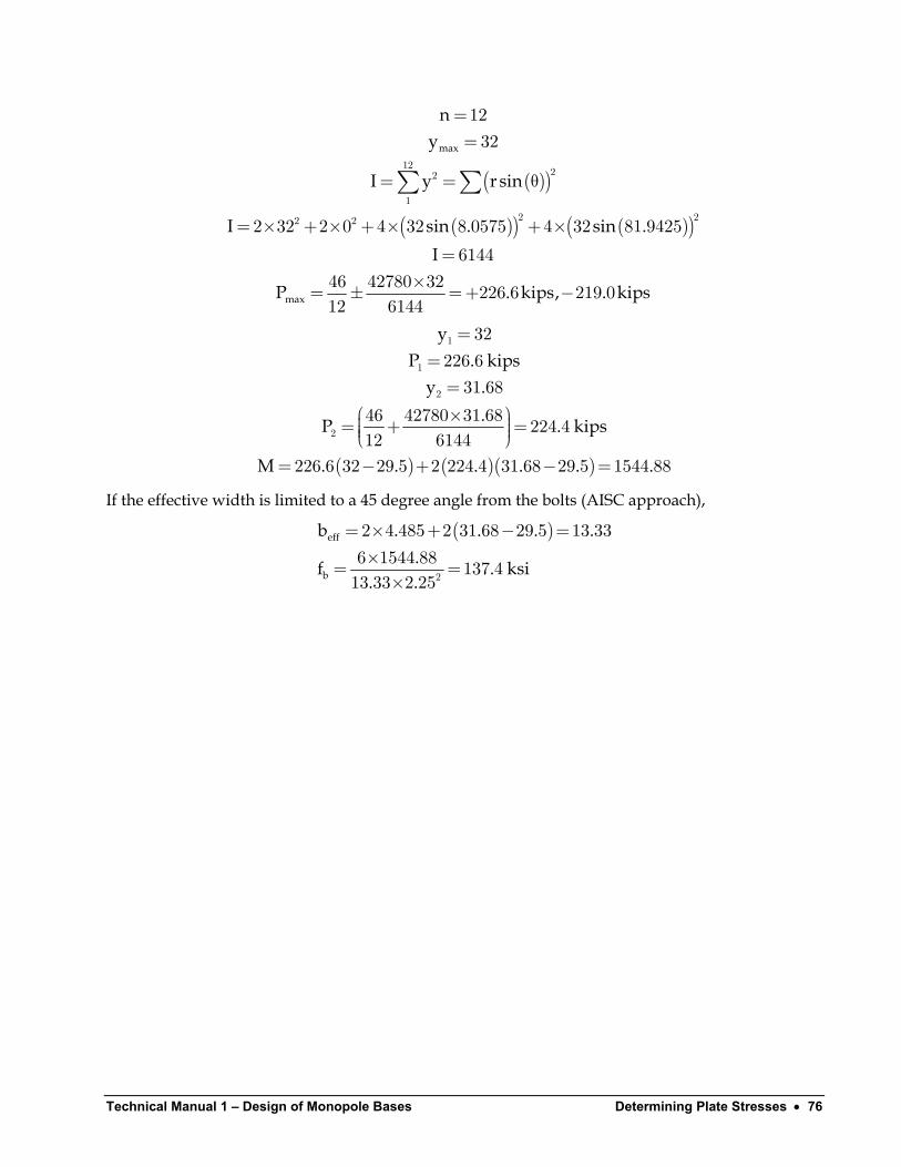
Technical Manual 1 – Design of Monopole Bases Determining Plate Stresses • 76
( )( )
( )( ) ( )( )
max
max
ny
I y r sin
I sin . sin .I
P . kips,
==
= = θ
= × + × + × + ×=
×= ± =+ −
∑ ∑12
22
12 22 2
1232
2 32 2 0 4 32 8 0575 4 32 81 9425
614446 42780 32 226 6 219 012 6144
. kips
( ) ( )( )
yP . kips
y ..P .
M . . . . . .
===
× = + = = − + − =
1
1
2
2
32226 631 68
46 42780 31 68 224 412 6144
226 6 32 29 5 2 224 4 31 68 29 5 1544 88
kips
If the effective width is limited to a 45 degree angle from the bolts (AISC approach),
( )eff
b
b . . ..f . ksi
. .
= × + − =×= =× 2
2 4 485 2 31 68 29 5 13 336 1544 88 137 413 33 2 25
.
Technical Manual 1 Design of Monopole Bases Determining Plate Stresses • 77
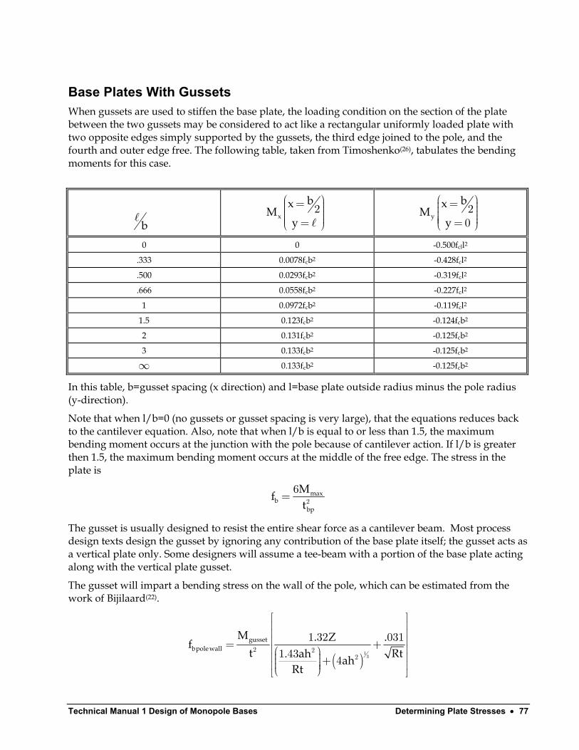
Base Plates With Gussets When gussets are used to stiffen the base plate, the loading condition on the section of the plate between the two gussets may be considered to act like a rectangular uniformly loaded plate with two opposite edges simply supported by the gussets, the third edge joined to the pole, and the fourth and outer edge free. The following table, taken from Timoshenko(26), tabulates the bending moments for this case.
b x
bxM
y
= = 2 y
bxM
y
= = 20
0 0 -0.500fcll2
.333 0.0078fcb2 -0.428fcl2
.500 0.0293fcb2 -0.319fcl2
.666 0.0558fcb2 -0.227fcl2
1 0.0972fcb2 -0.119fcl2
1.5 0.123fcb2 -0.124fcb2
2 0.131fcb2 -0.125fcb2
3 0.133fcb2 -0.125fcb2
∞ 0.133fcb2 -0.125fcb2
In this table, b=gusset spacing (x direction) and l=base plate outside radius minus the pole radius (y-direction).
Note that when l/b=0 (no gussets or gusset spacing is very large), that the equations reduces back to the cantilever equation. Also, note that when l/b is equal to or less than 1.5, the maximum bending moment occurs at the junction with the pole because of cantilever action. If l/b is greater then 1.5, the maximum bending moment occurs at the middle of the free edge. The stress in the plate is
maxb
bp
Mft
= 2
6
The gusset is usually designed to resist the entire shear force as a cantilever beam. Most process design texts design the gusset by ignoring any contribution of the base plate itself; the gusset acts as a vertical plate only. Some designers will assume a tee-beam with a portion of the base plate acting along with the vertical plate gusset.
The gusset will impart a bending stress on the wall of the pole, which can be estimated from the work of Bijilaard(22).
( )gusset
bpolewall
M . Z .ft Rt. ah ah
Rt
= + +
13
2 22
1 32 0311 43 4
Technical Manual 1 – Design of Monopole Bases Determining Plate Stresses • 78
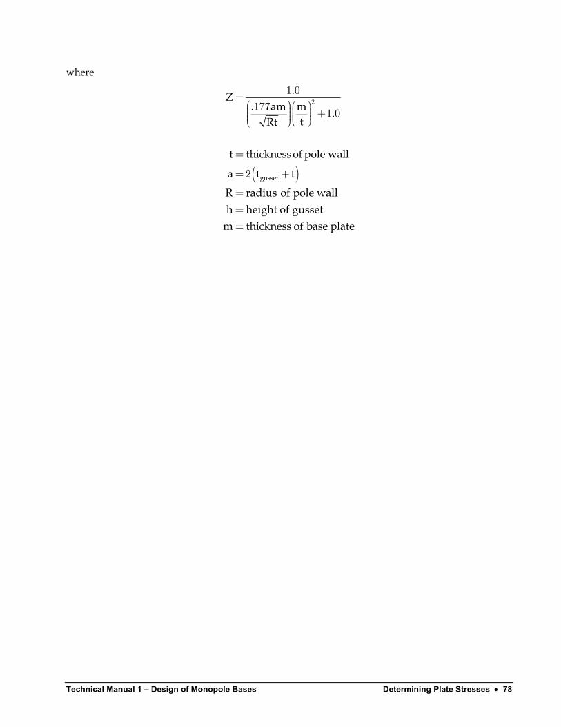
where
( )gusset
.Z. am m .
tRt
t thickness of pole wall
a t t
R radius of pole wallh height of gusset
m thickness of base plate
= +
=
= +
===
21 0
177 1 0
2

Technical Manual 1 Design of Monopole Bases Determining Plate Stresses • 79
Alternate Method 1 This method is identical to the Process Equipment Method with the following modifications.
1. D is taken to be the average diameter of the polygonal pole flat tipD DD
+=
2.
2. d is taken from the edge of the bolt rather than from the bolt circle bBC D dd − −=2
.
Alternate Method 2 This method is identical to the Process Equipment Method with following modifications.
1. D is taken to be the average diameter of the polygonal pole flat tipD DD
+=
2.
2. d is taken from the edge of the nut to the fillet weld nutw
BC D d− −= −2
d t .
Alternate Method 3 This method is identical to the Process Equipment Method with following modifications.
1. D is taken to be the average diameter of the polygonal pole flat tipD DD
+=
2.
2. d is taken from the edge of the nut to the fillet weld nutw
BC D d− −= −2
d t .
3. The plate is considered to be bent in double curvature such that the moment is one-half that of a cantilevered plate. This assumes that the bolt is considered capable of resisting such a moment. An equivalent procedure would be to adjust the bolt circle, BC, to a point midway between the bolt and the average diameter of the pole.
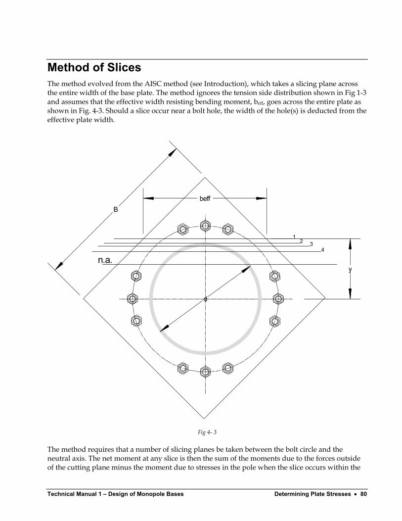
Technical Manual 1 – Design of Monopole Bases Determining Plate Stresses • 80
Method of Slices The method evolved from the AISC method (see Introduction), which takes a slicing plane across the entire width of the base plate. The method ignores the tension side distribution shown in Fig 1-3 and assumes that the effective width resisting bending moment, beff, goes across the entire plate as shown in Fig. 4-3. Should a slice occur near a bolt hole, the width of the hole(s) is deducted from the effective plate width.
n.a.
12 3
4
beff
y
d
B
Fig 4- 3
The method requires that a number of slicing planes be taken between the bolt circle and the neutral axis. The net moment at any slice is then the sum of the moments due to the forces outside of the cutting plane minus the moment due to stresses in the pole when the slice occurs within the
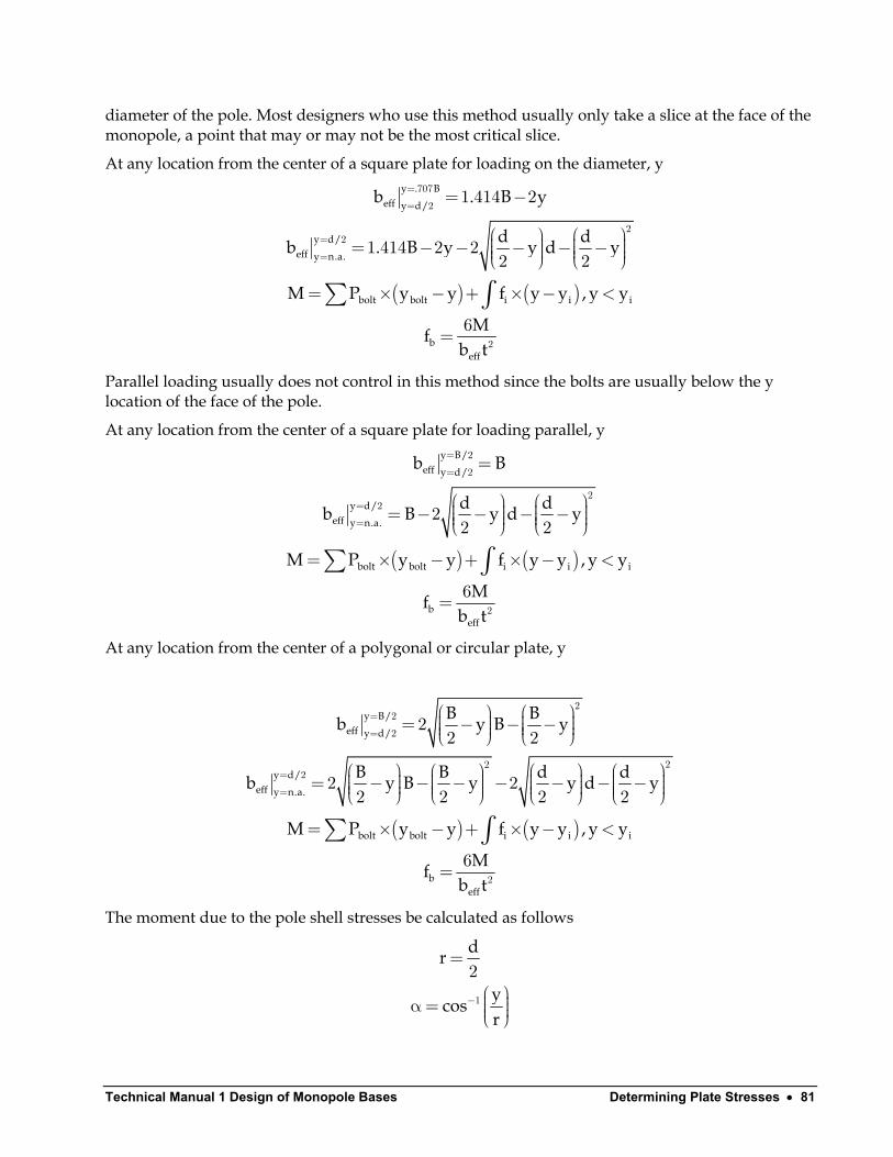
Technical Manual 1 Design of Monopole Bases Determining Plate Stresses • 81
diameter of the pole. Most designers who use this method usually only take a slice at the face of the monopole, a point that may or may not be the most critical slice.
At any location from the center of a square plate for loading on the diameter, y
( ) ( )
y . Beff y d/
y d/eff y n.a.
bolt bolt i i i
beff
b . B y
d db . B y y d y
M P y y f y y , y y
Mfb t
=
=
=
=
= −
= − − − − −
= × − + × − <
=
∑ ∫
707
2
22
2
1 414 2
1 414 2 22 2
6
Parallel loading usually does not control in this method since the bolts are usually below the y location of the face of the pole.
At any location from the center of a square plate for loading parallel, y
( ) ( )
y B/eff y d/
y d/eff y n.a.
bolt bolt i i i
beff
b B
d db B y d y
M P y y f y y , y y
Mfb t
=
=
=
=
=
= − − − −
= × − + × − <
=
∑ ∫
2
2
22
2
22 2
6
At any location from the center of a polygonal or circular plate, y
( ) ( )
y B/eff y d/
y d/eff y n.a.
bolt bolt i i i
beff
B Bb y B y
B B d db y B y y d y
M P y y f y y , y y
Mfb t
=
=
=
=
= − − −
= − − − − − − −
= × − + × − <
=
∑ ∫
22
2
222
2
22 2
2 22 2 2 2
6
The moment due to the pole shell stresses be calculated as follows
dr
ycosr
−
=
α= 1
2

Technical Manual 1 – Design of Monopole Bases Determining Plate Stresses • 82
( ) ( )
( ) ( )
polecos cosPtr MtrM cos cos d
A Scos sin cosPtr Mtrsin cos
A S sin co
α α θ− α= θ− α θ+ θ
− αd
cos
s α α− α α + α = α−α α + α−α α
∫ ∫22 2
0 0
22 2 3 12 2
2 21
2 2
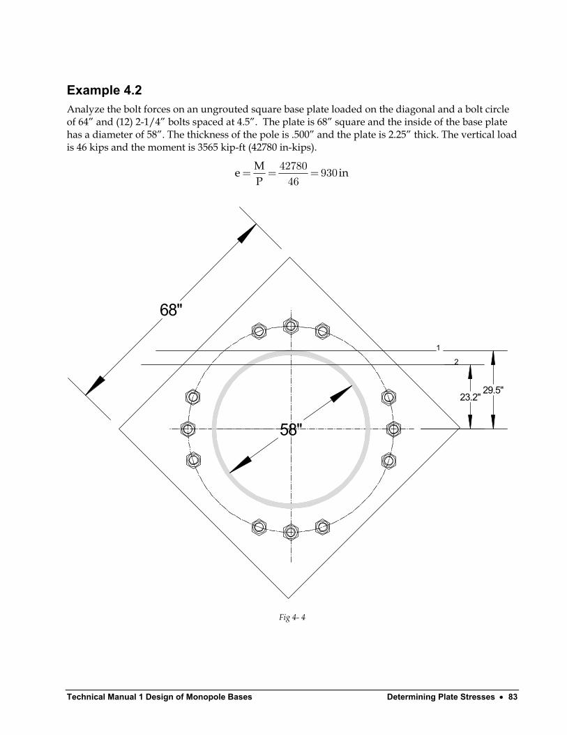
Technical Manual 1 Design of Monopole Bases Determining Plate Stresses • 83
Example 4.2 Analyze the bolt forces on an ungrouted square base plate loaded on the diagonal and a bolt circle of 64” and (12) 2-1/4” bolts spaced at 4.5”. The plate is 68” square and the inside of the base plate has a diameter of 58”. The thickness of the pole is .500” and the plate is 2.25” thick. The vertical load is 46 kips and the moment is 3565 kip-ft (42780 in-kips).
Me iP
= = =42780 93046
n
68"
58"
1
2
29.5"23.2"
Fig 4- 4
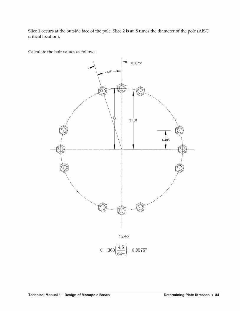
Technical Manual 1 – Design of Monopole Bases Determining Plate Stresses • 84
Slice 1 occurs at the outside face of the pole. Slice 2 is at .8 times the diameter of the pole (AISC critical location).
Calculate the bolt values as follows
32 31.68
4.485
4.5"
8.0575°
Fig.4-5
. .
θ= = π4 5360 8 057564
°
Technical Manual 1 Design of Monopole Bases Determining Plate Stresses • 85
( )( )
( )( ) ( )( )
max
max
n.a.
ny
I y r sin
I sin . sin .I
P . kips,
y . "
==
= = θ
= × + × + × + ×=
×= ± =+ −
×= =×
∑ ∑12
22
12 22 2
1232
2 32 2 0 4 32 8 0575 4 32 81 9425
614446 42780 32 226 6 219 012 6144
46 6144 5512 42780
. kips
( ) ( )( )
a
a
b
b
eff
yP . kips
y ..P .
b . . .M . . . . . .
.f . ksi. .
===
× = + = = × − × =
= − + − =×= =×
1
1
1
1
1
1
1 2
32226 631 68
46 42780 31 68 224 412 61441 414 68 2 29 5 37 152
226 6 32 29 5 2 224 4 31 68 29 5 1544 886 1544 88 49 2837 152 2 25
kips
This compares to 130.8 ksi using the Process Equipment Method.
Next, calculating the stress on slice 2
( )
( )
( ) ( )eff
y . d ..cos ..
A . in
I in
S.
b . . . . . .
−
= = α= =
π −= =
π −= =
= =
= × − × − − − − =
2
1
2 22
4 44
2
80 23 223 2 66529 5
59 5891 88
459 58
393116439311 133329 5
1 414 68 2 23 2 2 29 5 23 2 59 29 5 23 2 13 3.
Technical Manual 1 – Design of Monopole Bases Determining Plate Stresses • 86
( ) ( )( )
( ) ( ) ( )( )( ) ( )
pole
pole
. .M sin . . cos ..
. cos . sin . cos . .. .sin . . cos .
M
× × ×= − +
− +× × × −
= + =
2
2 3 122 2
2 46 5 29 5 665 665 66591 88665 665 665 665 6652 42780 5 29 5
1333 665 665 665
41 4495 4535
…
( ) ( )( )M . . . . .= − + − − =2 226 6 32 23 2 2 224 4 31 68 23 2 4535 1265
f .. .×= =×2 2
6 1265 112 7313 3 2 25
ksi
Technical Manual 1 Design of Monopole Bases Determining Plate Stresses • 87
Alternate Method 1 – Square Base Plates This alternate uses one slice at the face of the pole and limits the value of beff to no greater than the diameter of the pole.
Alternate Method 2 – Circular Base Plates This alternate uses one slice at the face of the pole and uses 90% of beff.
Boulos Method (New York Dept. of Transportation) As can be seen from Examples 4.1 and 4.2, there is a wide discrepancy between stresses calculated by the Process Equipment Method (used by industrial engineers for stacks) and those calculated by the Method of Slices (used by a number of pole manufacturers), especially if the slice location is limited to the face of the pole.
A research project was undertaken in 1993 at the New York State Department of Transportation Engineering Research and Development Bureau and sponsored by the Federal Highway Administration(5). The project performed full-scale testing and finite element analysis of traffic signal poles (square poles with four anchor bolts) to evaluate their structural adequacy. Results of testing and analysis of four poles indicated that they were structurally inadequate. The support base plate and anchor bolts were found to be deficient components, but the pole’s post was adequately designed. FEA models of the signal poles that verified the test results were then used to evaluate a representative sample of poles from three major suppliers. Results showed that plates designed by the manufacturers’ current (1993) methods of design were not adequate to carry the design loads. The report proposed a new design method for the base plate. This method is only applicable to square base plates. Since the testing was done on smaller ungrouted base plates commonly used for traffic poles having only four bolts, the method may not be totally applicable to larger diameter pole used for telecommunication purposes; however, it will provide educational background into the problem of determining stresses in base plates.
Boulos et al determined that both the parallel load and diagonal load cases resulted in three critical zones of stress. The diagonal case had a single zone at the narrowest part of the plate (45 degrees to the diagonal). The parallel case had two zones, each one at the narrowest part of the plate (0 degrees and 90 degrees).
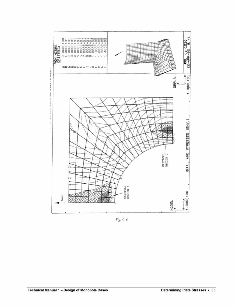
Technical Manual 1 – Design of Monopole Bases Determining Plate Stresses • 88
Fig. 4- 6
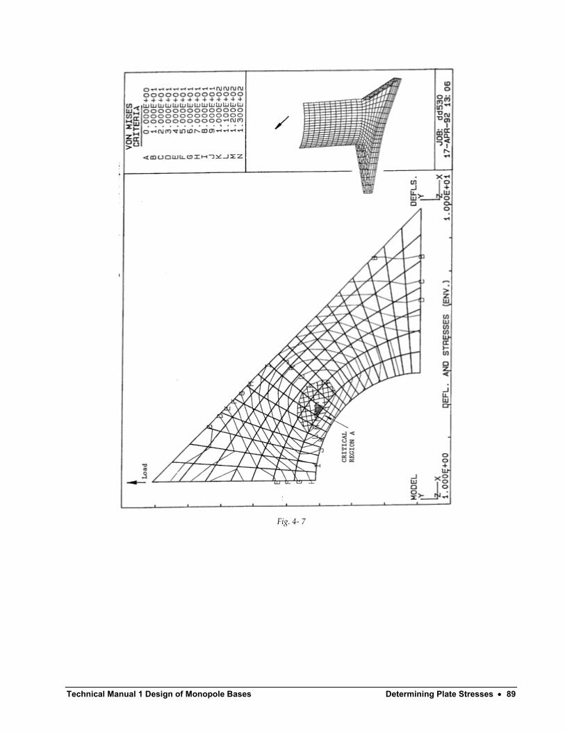
Technical Manual 1 Design of Monopole Bases Determining Plate Stresses • 89
Fig. 4- 7
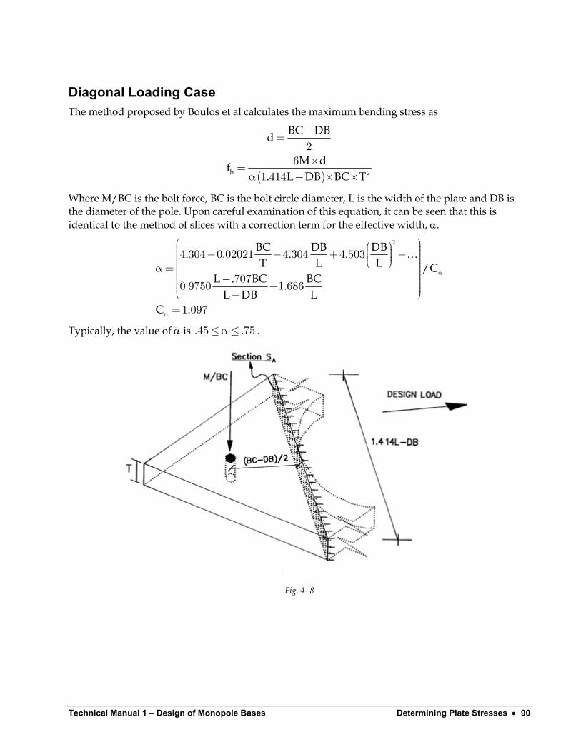
Technical Manual 1 – Design of Monopole Bases Determining Plate Stresses • 90
Diagonal Loading Case The method proposed by Boulos et al calculates the maximum bending stress as
( )b
BC DBd
M df. L DB BC T
−=
×=α − × × 2
26
1 414
Where M/BC is the bolt force, BC is the bolt circle diameter, L is the width of the plate and DB is the diameter of the pole. Upon careful examination of this equation, it can be seen that this is identical to the method of slices with a correction term for the effective width, α.
BC DB DB. . . .T L L /C
L . BC BC. .L DB L
C .
α
α
− − + − α= − − −=
2
4 304 0 02021 4 304 4 503
7070 9750 1 686
1 097
…
Typically, the value of α is . . . ≤α≤45 75
Fig. 4- 8
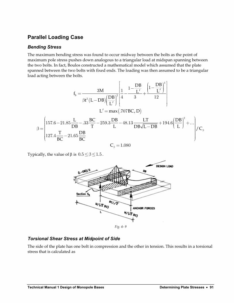
Technical Manual 1 Design of Monopole Bases Determining Plate Stresses • 91
Parallel Loading Case
Bending Stress The maximum bending stress was found to occur midway between the bolts as the point of maximum pole stress pushes down analogous to a triangular load at midspan spanning between the two bolts. In fact, Boulos constructed a mathematical model which assumed that the plate spanned between the two bolts with fixed ends. The loading was then assumed to be a triangular load acting between the bolts.
( )
( )
b
DBDBM LLf
DBt L DBL
L max . BC, D
L BC DB LT DB. . . . . .DB T L LDB L DB /C
T DB. .BC BC
−− ′′ = − + β − ′ ′=
− − − − + + − β= −
4
22
2
113 14 3 12
707
157 6 21 85 33 259 3 48 13 194 6
127 4 21 65
…
C .
β
β =1 080
Typically, the value of β is . . .≤β≤0 5 1 5
Fig. 4- 9
Torsional Shear Stress at Midpoint of Side The side of the plate has one bolt in compression and the other in tension. This results in a torsional stress that is calculated as
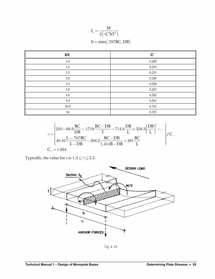
Technical Manual 1 – Design of Monopole Bases Determining Plate Stresses • 92
( )( )
vMfC bT
b min . BC, DB
=′γ
=
22
707
b/t C’ 1.0 0.208
1.2 0.219
1.5 0.231
2.0 0.246
2.5 0.258
3.0 0.267
4.0 0.282
5.0 0.291
10.0 0.312
∞ 0.333
BC BC DB DB DB. . . .DB T L L /C
L . BC BC DB BC. .L DB . B DB L
C .
γ
γ
− − − − + − γ= − − − + − −=
2
210 66 9 1719 714 8 358 3
70748 16 288 2 3811 414
1 094
…
Typically, the value for γ is 1 3 . . .≤γ≤2 3
Fig. 4- 10

Technical Manual 1 Design of Monopole Bases Determining Plate Stresses • 93
The method is valid for square base plates within the following ranges
BC. .T
DB. .LBC. .L
≤ ≤
≤ ≤
≤ ≤
8 0 16 5
0 5 0 75
0 95 1 05
These ranges are usually exceeded for telecommunication poles and the corresponding values will be < 0, thus suggesting that the lower bounds should be used. Therefore, it may be prudent to impose an upper limit on the effective width equal to .40 of the full slice width at the face of the pole for poles with four bolts. However it is reasonable to assume that, as the number of bolts increases, the effective width would increase above this value.
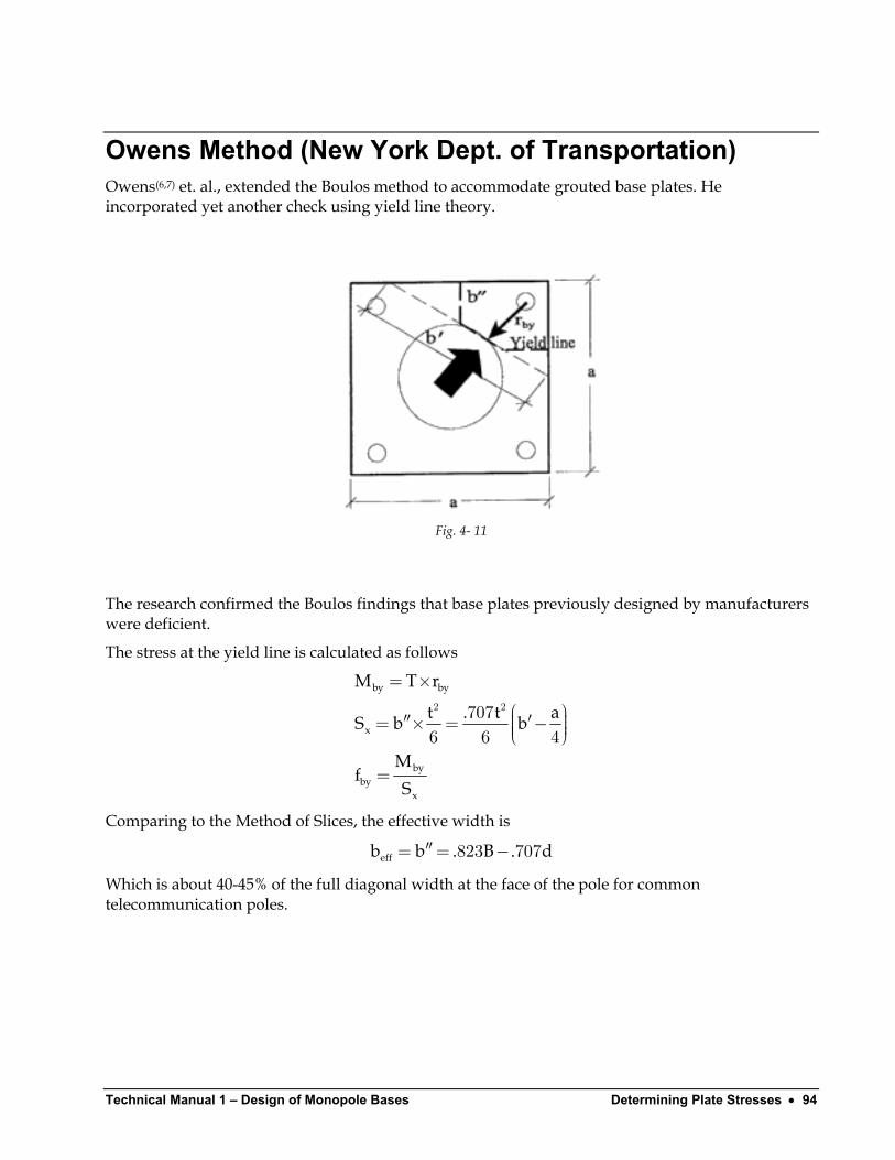
Technical Manual 1 – Design of Monopole Bases Determining Plate Stresses • 94
Owens Method (New York Dept. of Transportation) Owens(6,7) et. al., extended the Boulos method to accommodate grouted base plates. He incorporated yet another check using yield line theory.
Fig. 4- 11
The research confirmed the Boulos findings that base plates previously designed by manufacturers were deficient.
The stress at the yield line is calculated as follows
by by
x
byby
x
M T r
t . t aS b b
Mf
S
= ×
′′ ′= × = −
=
2 27076 6 4
d
Comparing to the Method of Slices, the effective width is
effb b . B .′′= = −823 707
Which is about 40-45% of the full diagonal width at the face of the pole for common telecommunication poles.
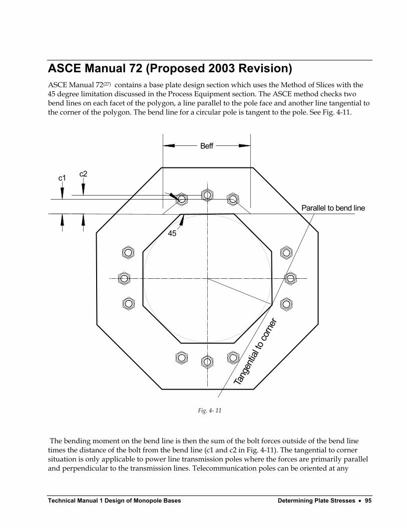
Technical Manual 1 Design of Monopole Bases Determining Plate Stresses • 95
ASCE Manual 72 (Proposed 2003 Revision) ASCE Manual 72(27) contains a base plate design section which uses the Method of Slices with the 45 degree limitation discussed in the Process Equipment section. The ASCE method checks two bend lines on each facet of the polygon, a line parallel to the pole face and another line tangential to the corner of the polygon. The bend line for a circular pole is tangent to the pole. See Fig. 4-11.
Beff
Parallel to bend line
45
c1 c2
Tang
entia
l to co
rner
Fig. 4- 11
The bending moment on the bend line is then the sum of the bolt forces outside of the bend line times the distance of the bolt from the bend line (c1 and c2 in Fig. 4-11). The tangential to corner situation is only applicable to power line transmission poles where the forces are primarily parallel and perpendicular to the transmission lines. Telecommunication poles can be oriented at any
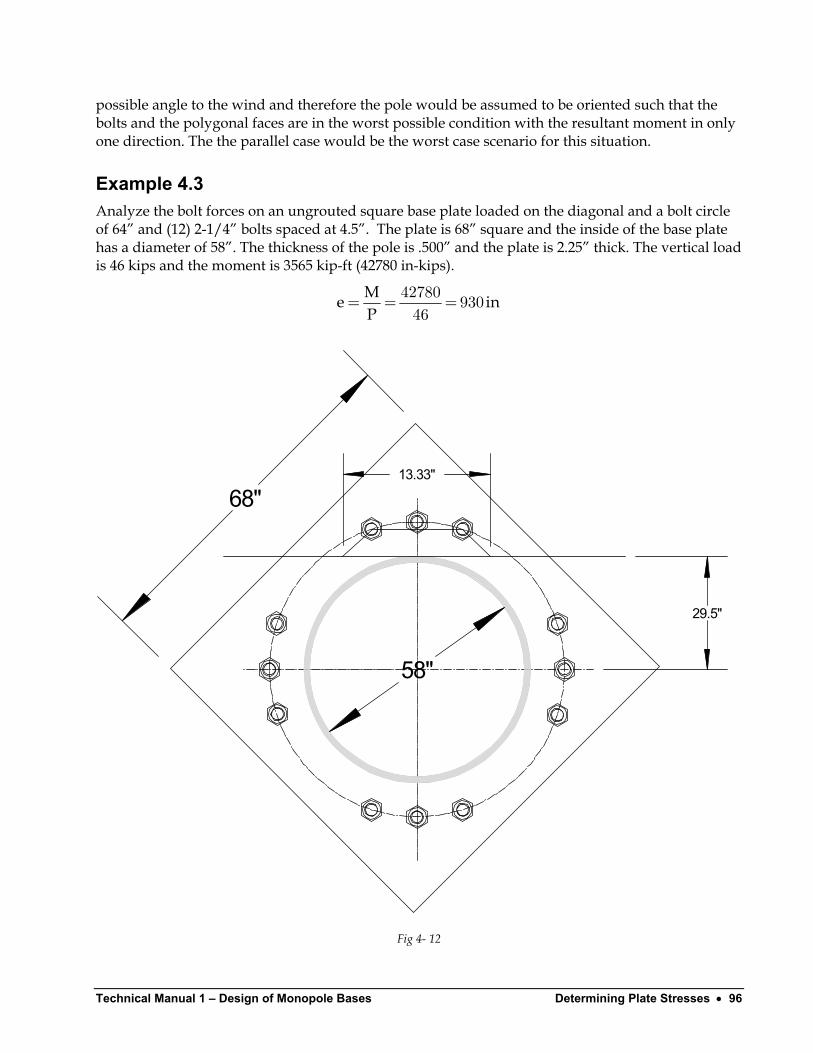
Technical Manual 1 – Design of Monopole Bases Determining Plate Stresses • 96
possible angle to the wind and therefore the pole would be assumed to be oriented such that the bolts and the polygonal faces are in the worst possible condition with the resultant moment in only one direction. The the parallel case would be the worst case scenario for this situation.
Example 4.3 Analyze the bolt forces on an ungrouted square base plate loaded on the diagonal and a bolt circle of 64” and (12) 2-1/4” bolts spaced at 4.5”. The plate is 68” square and the inside of the base plate has a diameter of 58”. The thickness of the pole is .500” and the plate is 2.25” thick. The vertical load is 46 kips and the moment is 3565 kip-ft (42780 in-kips).
Me iP
= = =42780 93046
n
68"
58"
29.5"
13.33"
Fig 4- 12

Technical Manual 1 Design of Monopole Bases Determining Plate Stresses • 97
Calculate the bolt values as follows
32 31.68
4.485
4.5"
8.0575°
Fig.4-5
. .
θ= = π4 5360 8 057564
°
Technical Manual 1 – Design of Monopole Bases Determining Plate Stresses • 98
( )( )
( )( ) ( )( )
max
max
ny
I y r sin
I sin . sin .I
P . kips,
==
= = θ
= × + × + × + ×=
×= ± =+ −
∑ ∑12
22
12 22 2
1232
2 32 2 0 4 32 8 0575 4 32 81 9425
614446 42780 32 226 6 219 012 6144
. kips
( )( ) ( )( )
a
a
b
b
eff
yP . kips
y ..P .
b . . . . inM . . . . . .
.f . ksi. .
===
× = + = = × + × − =
= − + − =×= =×
1
1
1
1
1
1
1 2
32226 631 68
46 42780 31 68 224 412 6144
2 4 485 2 31 68 29 5 13 33
226 6 32 29 5 2 224 4 31 68 29 5 1544 886 1544 88 137 413 33 2 25
kips
This compares to 49.28 ksi using the Method of Slices (Example 4.2).

Technical Manual 1 Design of Monopole Bases Anchor Bolts • 99
Anchor Bolts
Material Grades Over the years, a wide variety of bolt grades have been used for pole base plates. The most commonly used grades are listed below.
ASTM Designation Tensile Strength, ksi A307 60
A325 (SAE Gr 5 similar) 105
A354 Gr BD 150, 140 (over 2 ½”)
A354 Gr BC 125, 115 (over 2 ½”)
A449 90
A490 (SAE Gr 8 similar) 150
A618 Gr 75 (Anchor bolt grade, #18J bars) 100
A687 150
A36 58
A572 Gr 50 65
A572 Gr 42 60
A588 70
F1554 Gr 36 58
F1554 Gr 55 75
F1554 Gr 105 125
The current standard has anchor bolts unified under ASTM F1554 . Only grades 36 and 55 permit welding.
Hooked anchor bolts have fallen into disfavor as tests have shown that local crushing occurs at the bend point leading to a reduction in pullout capacity. The standard method detail is to provide a threaded portion at the bottom of the anchor bolt and attach a nut or nut with washer. When the grade permits welding, the nut is usually tack-welded to the bolt to insure that the nut does not

Technical Manual 1 – Design of Monopole Bases Anchor Bolts • 100
loosen or fall off. High strength grades usually do not permit welding and a second “jam” nut is often provided.
The number of anchor bolts required is a function of the maximum net uplift on the column and the allowable tensile load for the grade chosen. Prying forces in anchor bolts are typically neglected.
Fatigue is often ignored in the selection and sizing of anchor bolts. However, in cases of high seismic/wind situations fatigue may be a consideration. The following table shows some recommended values for bolt fatigue stresses.
Number of Cyclesa Allowable Tensile Stress, ksi 20,000 to 100,000 40
100,000 to 500,000 25
500,000 to 2,000,000 15
Over 2,000,000 10 aCategories correspond to AISC Appendix K
Technical Manual 1 Design of Monopole Bases Anchor Bolts • 101
Anchorage Prior to publication of ACI 318-02, anchorage of bolts was based upon approximate methods using pull-out “cones” as developed in AISC(12) and PCI(24). ACI 318 presented a new method for determining anchor bolt capacities. Appendix D of ACI 318-02 (ACI 2002) and Appendix B of ACI 349-01 both address the anchoring to concrete of cast-in-place anchors. Adhesive anchors and grouted anchors are not covered by these appendices. The provisions in both of these appendices are based upon the Concrete Capacity Design (CCD) Method.
In the CCD method the concrete cone is considered to be formed at a slope of 1 in 1.5 rather than the older 45 degree assumption. The cone is considered to have a square shape in plan rather than the classical round shape to simplify calculations.
Section 15.8.3.3 of ACI 318-02 requires that anchor bolts reach their design strength before anchorage failure or failure of the surrounding concrete (ductile failure) yet no code section is provided to state how this is to be accomplished.
Lutz-Fisher(23), outline a procedure to insure this ductility requirement. When an anchor bolt is designed to lap with reinforcement, the anchor capacity can be taken as se yA Fφ since the lap splice will insure that ductile behavior will occur. A is the tensile stress area of the anchor bolt and
as given in ACI 318-02 Chapter 9. To insure ducitlity for breakout, there must be sufficient lap length (with a standard hook on the reinforcing bars if required) to adequately develop the capacity. The distance “g” as shown in Fig. 5-1 is the distance from the centerline of the anchor bolt to the centerline of the nearest reinforcing bar. Using a Class B splice, the required embedment (top of concrete to top of nut) would be
se
.φ= 9
ef dgh . l top cov.
= + +1 31 5
er
When the anchor is solely resisted by concrete, as it would be for pullout and side-face blowout, one needs to have the concrete designed with additional capacity in order to insure ductility of the connection. To achieve this, Lutz proposed that the concrete must reach a capacity of ( )se y. A Fφ51 2
thereby insuring that the steel would yield prior to concrete rupture.
Technical Manual 1 – Design of Monopole Bases Anchor Bolts • 102
hef
Hooked bars if required
g
11.5
Potential failure plane
1.3ld
Fig. 5- 2 Development of bar for concrete breakout
Technical Manual 1 Design of Monopole Bases Anchor Bolts • 103
Example 4.1 An anchor bolt has a factored (USD) bolt tension of 50 kips. There are 8 anchor bolts and the anchor bolts are 10 inches from the edge of a 60 inch diameter concrete pier and the bolts are 1-1/4” F1554 Gr 55. There are 24-#9 Gr 60 reinforcing bars bundled in groups of 2, 3 inches clear from the edge of the pier and the concrete strength is 3500 psi. The basic development length of a #9 bar with 3 inches clear is 37 inches (straight bar).
3"
10"
9"
60"
Fig 5-2
Check tension capacity of 2-#9 bars
cap b yP . nA F . . o.φ = × × = × × × =90 90 2 1 0 60 108 k.
The anchor bolt capacity is
Technical Manual 1 – Design of Monopole Bases Anchor Bolts • 104
s se utN . A F . . . kipφ = × × = × × =75 75 969 75 54 5 s
Breakout Ductility for breakout will be insured by lapping the bolt with the reinforcing bars.
d
d
ef d
l in. l in
gh . l cover in, say '. .
==
≥ + + = + + =
371 3 48
91 3 48 3 57 51 5 1 5
Pullout To insure ductility for pull-out and side-face blowout, the concrete strength must be greater than
( )se ykips. A F . . . boltφ = × × × =1 25 1 25 0 9 969 55 60
Using a nut diameter of 2.1”, the pullout strength is
( ) ( )pn p brg c
brg
pn
N N . . A f
. .A .
N . . . . kips o.
′φ =φψ =
− =π = φ = × × × × = ≥
4
2 2
70 1 4 8
2 1 1 25 2 2364
70 1 4 2 236 8 3 5 61 60 k.
Often the anchor bolts are held together with a ½” setting plate ring. This would increase the bearing area but might not be fully effective since the plate would bend during pullout. An assumption could be made that the bearing would be equivalent to a washer which would have an outside diameter of two times the bolt diameter.
Side-Face Blowout The side clearance, c , is 10”. Since , side-face blowout must be checked. The side-face blowout strength is
efc . h≤ 4
osbg brg c
sN . c A fc.. . . ki
′φ = + = + × × = ≥ ×
75 1 160618 8575 1 160 10 2 236 3500 139 5 606 10
ps o.k.
Normally, side-face blowout would not need to be checked if ties are provided in the region at the anchor bolt nut location such that the ties would cross the failure plane.
Technical Manual 1 Design of Monopole Bases Recommendations • 105
Recommendations
Determining Base Plate Forces
Grouted Base Plates All of the methods presented yield approximately the same results. However, the Complete Methods are more accurate when there are a limited number of bolts. The Complete Methods also have specific methods for square base plates, which can only be approximated as circular using the Process Equipment or Lutz Methods.
Therefore, the Complete Method should be modified to obtain a more reasonable distribution of plate stresses considering that the plate is not infinitely rigid. The following two modifications should be made:
1. The distance from the bolt circle to the outside edge of the plate should be limited to the distance from the pole face to the bolt circle.
2. The plate hole opening diameter should be taken as no less than the inner diameter of the pole minus the distance from the pole face to the adjusted outside edge of the plate.
Ungrouted Base Plates The method of calculating bolt forces using the section modulus of the bolt group is the only method currently being used.
Determining Base Plate Stresses The Method of Slices without any adjustment to the effective width was proven inaccurate by the work of Boulos and Owens. The method should only be used for square base plates whenever the effective width of plate at the face of the pole is multiplied by an adjustment factor . The factor would be approximately 0.40 for four bolt base plates and would increase for poles with more than four bolts.
The Process Equipment Method of considering the plate as a simple cantilever from the center of the bolt circle to the face of the pole is still the simplest method for circular or polygonal plates and yields results for square base plates, when using the 45 degree rule, that are comparable to those

Technical Manual 1 – Design of Monopole Bases Recommendations • 106
obtained by using the Boulos method when using a lower bound of .40 on effective width. There was no evidence in the research that would support the assumptions in any of the Alternate Methods although they may have some validity.
The ASCE Manual 72 (Proposed) Method is identical to the aforementioned Process Equipment Method using the 45 degree rule.
The Process Equipment Method (45 degree rule)/ASCE Manual 72 Method is therefore recommended using the parallel bend line and the worst case positioning of pole facets and bolts.
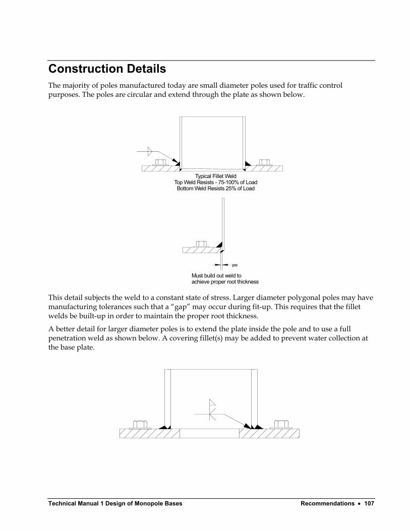
Technical Manual 1 Design of Monopole Bases Recommendations • 107
Construction Details The majority of poles manufactured today are small diameter poles used for traffic control purposes. The poles are circular and extend through the plate as shown below.
gap
Typical Fillet WeldTop Weld Resists - 75-100% of LoadBottom Weld Resists 25% of Load
Must build out weld toachieve proper root thickness
This detail subjects the weld to a constant state of stress. Larger diameter polygonal poles may have manufacturing tolerances such that a “gap” may occur during fit-up. This requires that the fillet welds be built-up in order to maintain the proper root thickness.
A better detail for larger diameter poles is to extend the plate inside the pole and to use a full penetration weld as shown below. A covering fillet(s) may be added to prevent water collection at the base plate.
Technical Manual 1 – Design of Monopole Bases Bibliography • 108
Bibliography
References 1. Design of Steel Transmission Pole Structures, Manual 72, American Society of Civil Engineers (ASCE).
2. Standard Specifications for Structural Supports for Highway Signs, Luminaires and Traffic Signals, American Association of State Highway Transportation Offices (AASHTO).
3. Guide Specifications for Design of Metal Flagpoles, The National Association of Architectural Metal Manufacturers (NAAMM).
4. Metal Flagpole Manual, The National Association of Architectural Metal Manufacturers (NAAMM).
5. Research Report 159, Load Testing, Finite Element Analysis, And Design of Steel Traffic-Signal Pole, Boulos, Fu, and Alampalli, New York State Department of Transportation.
6. Research Report 131, A Simplified Design Procedure For End-Plates and Base-Plates Of Cantilevered Traffic Structures, Frank Owens, Osman Hag-Elsafi, Sreenivas Alampalli, New York State Department of Transportation.
7. New Procedure For Design of End Plates and Base Plates of Cantilevered Traffic Support Structures, Osman Hag-Elsafi, Sreenivas, and Frank Owens, ASCE Journal of Structural Engineering, October 2001.
8. Design of Welded Structures, Blodgett, Lincoln Arc Welding.
9. Design of Steel Structures, Gaylord and Gaylord.
10. Steel Structures, McGuire.
11. Steel Structures, Design and Behavior, Salmon and Johnson.
12. Steel Design Guide Series 1, Column Base Plates, American Institute of Steel Construction (AISC).
13. Column Base Plates with Axial Loads and Moments, DeWolf, ASCE Journal of Structural Engineering, November 1980.
14. Base Plates Under Axial Loads and Moments, Thambiratnam, ASCE Journal of Structural Engineering, May 1986.
15. Concrete Plain and Reinforced, Taylor, Thompson, and Smulski, 1925.
16. Process Equipment Design, Brownell and Young , 1957.
Technical Manual 1 Design of Monopole Bases Bibliography • 109
17. Tubular Steel Structures, Theory and Design, Troitsky , Lincoln Arc Welding 1990.
18. Pressure Vessel Handbook, Megyesy.
19. Pressure Vessel Handbook, Bednard , 1991.
20. Internal Memorandum, Computerized Structural Design, Dr. Leroy Lutz, 2004.
21. Internal Memorandum, Computerized Structural Design, Daniel Horn, 2004.
22. Design of Plate Structures – Volume 2, Bijilaard, American Iron and Steel Institute (AISI).
23. Steel Design Guide Series #7, Industrial Buildings, Roofs to Column Anchorage, Lutz-Fisher, American Institute of Steel Construction (AISC), 2004.
24. Prestressed Concrete Design Handbook, Presressed Concrete Institute (PCI).
25. Formulas for Stress and Strain, Roarke.
26. Theory of Plates and Shells, Timoshenko.
27. ASCE Manual 72, Guide for Design of Steel Transmission Pole Structures, American Society of Civil Engineers (ASCE)

Technical Manual 1 Design of Monopole Bases Glossary of Terms • 111
Glossary of Terms
AASHTO American Association of State Highway Transportation Officials.
AISC American Institute of Steel Construction.
AISI American Iron and Steel Institute.
ASCE American Society of Civil Engineers.
Base Plate A steel plate that transmit forces from a column to the foundation.
Monopole A stepped or tapered steel pole. Poles can be round or polygonal (8,12,16, or 18 sides).
NAAMM National Association of Architectural Metal Manufacturers.
PCI Prestressed Concrete Institute.

Determining Bolt Forces 66 Determining Bolt Shear 71 Diagonal Loading Case 91
Index E
Effective Width Based Upon Plate Theory 74 Example 1.1 9 Example 1.2 14 Example 1.3 17 Example 2.1 26 Example 2.2 31 Example 2.3 38 Example 2.4 47, 58
A Example 2.5 63 Example 3.1 68 AASHTO 111 Example 3.2 69 AISC 111 Example 3.3 69 AISC Method For Building Columns 7 Example 4.1 79, 104 AISI 111 Example 4.2 87 Alternate Method 1 80 Example 4.3 101 Alternate Method 1 - Square Base Plates 90
Alternate Method 2 83 F Alternate Method 2 - Circular Base Plates 91
Alternate Method 3 87 Flexible Base Plate 8 Anchorage 104 ASCE 111 G ASCE Manual 72 (Proposed 2003 Revision) 99
Grouted Base Plates 107 B
H Base Plate 111
Historical Perspective 2 Base Plates With Gussets 79 Bending Stress 95
I Bending Stresses In Bolts 71 Boulos Method (New York Dept. of
Transportation) 91 Introduction 72
Breakout 105 L
Lutz Modification 29 C
Complete Circular Base Plate Method 63 M Complete Square Base Plate - Load On Diagonal
33 Material Grades 104 Method of Slices 87 Complete Square Base Plate - Load Parallel 50 Modification for Clipped Corners 36 Monopole 111 D
Determining Base Plate Forces 105 Determining Base Plate Stresses 108
Technical Manual 1 Design of Monopole Bases Index • 113
Technical Manual 1 – Design of Monopole Bases Index • 114
N
NAAMM 111
O
Organization 1 Owens Method (New York Dept. of
Transportation) 99
P
Parallel Loading Case 94 PCI 111 Process Equipment Design Method 19 Process Equipment Methods 77 Pullout 105
S
Side-Face Blowout 105 Stiff Plate Approach 12
T
Technical Manual 1-1 43 Technical Manual 1-2 54 Technical Manual 1-3 79 Torsional Shear Stress at Midpoint of Side 96
U
Ungrouted Base Plates 108