Embed Size (px)
Citation preview

CCD COLOR DIGITALCAMERA MODULE
DFW-V500DFW-VL500
TechnicalManual
(Ver. 1.0) English

DFW-V500DFW-VL500
Table of Contents
OUTLINE ..................................................................................................................... 1
MAIN FEATURES ...................................................................................................... 1
SYSTEM COMPONENTS .......................................................................................... 2
SPECIFICATIONS ...................................................................................................... 3
CONNECTION ............................................................................................................ 4
NAMES AND FUNCTIONS OF PARTS ................................................................... 5
DIMENSIONS ............................................................................................................. 6
CCD PIXEL LOCATION ............................................................................................ 7
SPECTRAL CHARACTERISTICS (TYPICAL VALUES) ....................................... 8
FUNCTIONS................................................................................................................ 9
SETTINGS OF CAMERA CONTROL AND STATUS REGISTER ......................... 13
COMMAND SENDING PROCEDURE UNTIL IMAGES ARE DISPLAYED ........ 22
COMMAND SETTING AND OPERATION TIMING .............................................. 24
SHUTTER .................................................................................................................... 33
HOST ADAPTER CARD DFWA-400 ........................................................................ 36

1
DFW-V500DFW-VL500
The DFW-V500/VL500 is a color digital video camera utilizing a 1/3-type PS IT CCD. The DFW-V500 is the C-mounted type
while the DFW-VL500 is a 12× zoom lens mounted type.
The IEEE1394-1995 digital interface realizes a transfer speed of 400M bps and outputs VGA (640 × 480)/YUV (4 : 2 : 2)/30 fps.
In addition, the DFW-V500/VL500 also adopts a primary color filter CCD to realize good color reproductivity. Furthermore, they
digitally transmit the original image quality without “Analog-to-Digital conversion” on the video capture board. The square
pixels eliminate the need for aspect ratio conversion in the image processor.
OUTLINE
1/3-type progressive scan IT CCD
Primary color filter/square pixel/progressive scan CCD
Non-compressed YUV (4 : 2 : 2) 8 bits each
External trigger functionThe external trigger shutter function allows the image exposure to be coordinated with external equipment and moving
objects. The exposure time can be controlled via software over the IEEE1394 bus.
Solid aluminum diecast chassis
C-Mount with Flange-Back adjustment (DFW-V500)
Remote control of camera settings and operation via IEEE-1394 commands
MAIN FEATURES

2
DFW-V500DFW-VL500
SYSTEM COMPONENTS
Video Camera ModuleDFW-V500
IEEE1394 Cable(6-pin, 4.5 m)
Host Adapter Card (Option)DFWA-400
C-mount Lens (Option)
• VCL-08YM• VCL-12YM• VCL-16Y-M• VCL-25Y-M• VCL-50Y-M• J6 × 11 MACRO (Canon)
Video Camera ModuleDFW-VL500

3
DFW-V500DFW-VL500
SPECIFICATIONS
Image sensorNumber of effective pixelsCell sizeInterface formatProtocolData format
Frame rateTransfer speedLens mount
DFW-V500DFW-VL500
Flange backDFW-V500 only
Minimum illuminationDFW-V500DFW-VL500
White balance
HUESaturationBrightnessZoom/Focus
DFW-VL500 onlyGammaCCD irisShutterGain
External trigger shutterSupply voltage/power consumptionOperating temperature/storage temperatureDimensions
DFW-V500DFW-VL500
MassDFW-V500DFW-VL500
Accessories
: 1/3-type progressive scan IT CCD
: 659 (H) × 494 (V)
: 7.4 (H) × 7.4 (V) µm
: IEEE1394-1995
: 1394-based Digital Camera Specification Version 1.20
: 640 × 480 YUV (4 : 2 : 2) 8 bits each Mode-3
640 × 480 YUV (4 : 1 : 1) 8 bits each Mode-2
320 × 240 YUV (4 : 2 : 2) 8 bits each Mode-1
160 × 120 YUV (4 : 4 : 4) 8 bits each Mode-0
: 3.75, 7.5, 15, 30 fps and One Shot
: 100M, 200M, 400M bps
: C-mount
: Built-in 12× zoom lens
When the shooting distance is infinite, the focus distance Tele side is 64 mm,
Wide side is 5.5 mm
0.8 m at whole MOD zoom area, 1 cm at Wide end (distance from lens tip)
: 17.526 mm
: 6 lx (F1.2)
: 14 lx (F1.8, Wide end)
: One Push (Color temperature during automatic adjustments: 2,400 K to 10,000 K)/
ATW (Color temperature during automatic adjustments: 2,800 K to 6,500 K)
(Auto tracing)/
3,200 K, 5,600 K, Manual adjustment
: Adjustable
: Adjustable
: Adjustable
: Adjustable/Manual adjustment (using the buttons on top side of the camera)
: Switchable between three positions
: ON (1/30 to 1/2,000)/OFF
: 5s to 1/15s, 1/30s to 1/10,000s, 1/20,000s, 1/50,000s, 1/100,000s
: Auto adjustment/Manual adjustment (0 to 18 dB, 1 dB/step)
AGC operation range is the same as above
: ON/OFF
: DC +8 to +30 V (from IEEE1394 cable)/4 W
: –10 to +50°C/–20 to +60°C
: 60 (W) × 61 (H) × 116.7 (D) mm
: 60 (W) × 61 (H) × 118.5 (D) mm
: Approx. 305 g
: Approx. 335 g
: IEEE1394 cable (1), Lens mount cap (1) ... DFW-V500
Lens cap (1) ... DFW-VL500, Clamp filter (2)
External trigger connector (male) (1), Operating Instructions (1)

4
DFW-V500DFW-VL500
CONNECTION
Recommended Lens:VCL-08YMVCL-12YMVCL-16Y-MVCL-25Y-MVCL-50Y-MJ6 × 11 MACRO (Canon)
DFW-V500
IEEE1394 Cable
DFWA-400
Host Adapter Card
C-mount Lens
Host Equipment (PC, etc.)
Display
DFW-V500
DFW-VL500
DFW-VL500
IEEE1394 Cable
DFWA-400
Host Adapter Card
Host Equipment (PC, etc.)
Display

5
DFW-V500DFW-VL500
NAMES AND FUNCTIONS OF PARTS
q Lens mount (C-mount) (DFW-V500)w Built-in zoom lens (DFW-VL500)e Flange back hole (DFW-V500)
Adjust the flange back using a standard head screwdriver.r Screw hole for tripod mountingt Camera fixing reference holesy TRIG IN (Trigger) connector
Inputs the TTL level, negative polarity trigger signal.u Camera connector (IEEE1394 connector)
Connect to the host equipment using the IEEE1394 cableprovided.
yyyyy Pin assignment of TRIG IN connector (female) uuuuu Pin assignment of camera connector
i Pilot lampLights green when the power is turned on, and orange in theisochronous transmission (enabled) state.
o ZOOM buttons (DFW-VL500)Press the “T (telephoto)” side to obtain a smaller angle of view andthe “W (wide-angle)” side to have a larger angle of view.
!0 FOCUS buttons (DFW-VL500)Press the “F” side to focus on farther objects and the “N” side tofocus on closer objects.
!1 Filter screw (DFW-VL500)Connect a 37 mm aperture filter here.
DFW-V500
DFW-VL500
Digital Interface
DFWDFW-V500-V500
TRIG IN
1
8
3
6 7
4
5
10
911
2
8
OPTICAL 12X ZOOM LENS
Digital InterfaceDigital Interface
DFWDFW-VL500-VL500
TRIG INTRIG IN
FT
FO
CU
SF
OC
US
ZO
OM
ZO
OM
NW
6 7
4
5
1. NC2. GND3. TRIG IN4. NC
1
2
4
3
2
1
4
3
6
5
1. Power2. Power (GND)3. TPB–4. TPB+5. TPA–6. TPA+

6
DFW-V500DFW-VL500
15
16.15.1
OPTICAL 12X ZOOM LENS
60
31
61
M37 P0.75 118.5
Digital InterfaceDigital Interface
DFWDFW-VL500-VL500
TRIG INTRIG IN
25
20.8
48.8
56
1/4" -20UNC
4-M3 (Effective Depth 5)
FT
FO
CU
SF
OC
US
ZO
OM
ZO
OM
NW
15
16.15.160
31
611" -32UNC
25
19
47
56
1/4" -20UNC
4-M3 (Effective Depth 5)
116.7
Digital InterfaceDigital Interface
DFWDFW-V500-V500
TRIG INTRIG IN
DIMENSIONS
DFW-V500
Unit: mm
DFW-VL500
Unit: mm

7
DFW-V500DFW-VL500
H
V
Output Pixel Area
Effective Pixel Area
10 640
2
2 659 31
494
8
480
7
CCD PIXEL LOCATION
Total number of pixels : 692 (H) × 504 (V)
Number of effective pixels: 659 (H) × 494 (V)
Number of output pixels : 640 (H) × 480 (V)
Unit cell size : 7.4 µm (H) × 7.4 µm (V)
Top View
Note) Center of output pixel area is luminous axis.

8
DFW-V500DFW-VL500
SPECTRAL CHARACTERISTICS (TYPICAL VALUES)
400 500
Wavelength [nm]
B G
R
Rel
ativ
e R
espo
nse
600 700

9
DFW-V500DFW-VL500
FUNCTIONS
The DFW-V500/VL500 differs from conventional analog cameras in that no video signals will be output by just supplying power.
It will start operating when designated commands are written in the CSR (Control & Status Register) specified in the 1394-based
Digital Camera Specification Ver.1.20. For details on the steps to video signal output and details of CSR, refer to “SETTINGS OF
CAMERA CONTROL AND STATUS REGISTER” on page 13 and “COMMAND SENDING PROCEDURE UNTIL IMAGES
ARE DISPLAYED” on page 22.
This chapter describes the functions of the camera which can be set using the CSR.
Camera Functions
GainUsed for setting the gain of the video signal amplifier. The gain can be set in 18 steps between the standard gain and maximum
+18 dB.
By setting AUTO to ON, the gain will be automatically adjusted to the appropriate exposure. The range of operation is 0 to
+18 dB.
Note) For 18 dB, there may be an inconsistency of approximate +3 dB.
1 step is about 1 dB.
ShutterThe CCD exposure time can be set between the maximum 5 seconds and minimum 1/100,000 seconds. By setting the CCD
Iris to ON, the exposure time will be automatically adjusted to the appropriate exposure. The range of operation is 1/30 to
1/2,000 seconds.
Iris (DFW-VL500 only)Used for setting the built-in zoom lens iris from fully opened (F1.8 at Wide end) to fully closed. By setting AUTO to ON, the
iris will be automatically adjusted to the appropriate exposure. The range of operation is about F1.8 to F32.
These values are approximate values and may differ according to
the adjusted and operating state of the camera.
Auto ExposureUsed for setting the exposure compensation when Gain, Shutter, or Iris is operating in the AUTO mode. When Gain, Shutter,
and Iris are all set to Manual, the Auto Exposure setting will not be used. The range of operation is about –1EV to +0.5EV.
Operation ranges of AGC, Lens Iris, CCD Iris
When DFW-VL500
When DFW-V500 (Lens Iris: F = 5.6)
EV4
AGC Lens Iris CCD Iris
EV7 EV22EV16
EV7
AGC CCD Iris
EV10 EV16

10
DFW-V500DFW-VL500
FUNCTIONS
BrightnessThe brightness of images can be controlled by changing the black level setting. Adjust the brightness if the appropriate
gradation cannot be obtained due to the blurring of the black portions of the image.
When maximum value of Y output data is 255
Command setting Y output value (full black level)
----------------------------------------------------------------------------
00h 0
80h 1
FFh 50
These values are approximate values and may differ
according to the adjusted state of the camera.
GammaUsed for setting gamma compensation to ON or OFF.
ON : For obtaining natural gradation taking into account the characteristics of the monitor.
OFF (1) : Outputs CCD signals for image processing linearly according to the sensitivity when Gamma is ON.
OFF (2) : Outputs CCD signals for image processing linearly. The sensitivity drops, but the dynamic range increases
from OFF (1).
Concept of Gamma Characteristics
SharpnessUsed for adjusting sharpness of the image.
White BalanceUsed for adjusting white balance by adjusting R-gain and B-gain. White subjects can be shot in white by setting the white
balance according to the color temperature of the luminance light. The White Balance operation mode can be selected from
three modes – Manual, One Push, and ATW.
Input
Gamma OFF (2)
Gamma OFF (1)
Gamma ON
Out
put

11
DFW-V500DFW-VL500
FUNCTIONS
Color TemperatureThis function was originally intended for selecting the optical filter. However with the DFW-V500/VL500, the R-gain and B-
gain are set to the appropriate White Balance when color temperatures 3,200 K and 5,600 K light sources are used.
HueUsed for adjusting the hue of the image.
Command setting Hue changing amount
-----------------------------------------------------------------------------------------------------------------------
00h Equivalent changing amount when the luminance point of the
NTSC Vector Scope is rotated by about 15 degrees in the
clockwise direction from the factory setting.
80h Factory setting
FFh Equivalent changing amount when the luminance point of the
NTSC Vector Scope is rotated by about 15 degrees in the
counterclockwise direction from the factory setting.
These values are approximate values and may differ
according to the adjusted state of the camera.
SaturationUsed for adjusting the saturation of the image.
Command setting Saturation changing amount
-------------------------------------------------------------------------
00h 0%
80h 100% (Factory setting)
FFh Approx. 200% Saturation
These values are approximate values and may differ
according to the adjusted state of the camera.
Zoom (DFW-VL500 only)Used for adjusting the zoom range of built-in zoom lens.
Focus (DFW-VL500 only)Used for adjusting the focus of the built-in zoom lens.
Isochronous Start/StopUsed for turning ON/OFF the output of IEEE1394 isochronous transmitted images. When an image is being transmitted, the
LED in front of the camera will light up orange.

12
DFW-V500DFW-VL500
FUNCTIONS
TriggerUsed for setting the external trigger mode to ON or OFF. No normal moving image signals are output in this mode.
Isochronous output is stopped at the point Trigger ON is set even in the Isochronous ON state. When external trigger pulses
(TTL level, negative polarity, pulse width above 1 ms) are input, one image (one frame) is exposed for the specified time
(specified at the shutter) will be output at the end of exposure.
The time from input of external trigger pulse to the start of image data output varies according to the exposure time and timing
of the external trigger pulse for the reference pulse (VD) inside the camera.
Memory_Save/Mem_Save_Ch/Cur_Mem_ChUsed for memorizing the current camera setting data in the internal memory of the camera. Two types of settings can be
memorized. These are called Memory_Channels 1 and 2.
To memorize the settings, first specify the Memory_Channel recorded at Mem_Save_Ch, and then memorize with
Memory_Save.
The memorized setting data can be read out and reset to the camera. The Memory_Channel to be read out can be specified and
executed at the same time with the Cur_Mem_Ch. It is also possible to return it to the factory setting.
<Settings that are saved>
• Frame Rate • Saturation
• Video Mode • Gamma
• Video Format • Shutter
• Iso Channel Speed • Gain
• Memory Save Channel • Iris (DFW-VL500 only)
• Brightness • Focus (DFW-VL500 only)
• Auto Exposure • Trigger
• Sharpness • Zoom (DFW-VL500 only)
• White Balance • Optical Filter
• Hue
One ShotUsed for capturing only one image data (one frame) in the Isochronous OFF state, then transmitted in the Isochronous ON
state. The difference between this function and Trigger described in the next section is that image input is started by the
IEEE1394 command instead of external trigger signals. The timing at which exposure starts is also undefined (within 70 ms
after the command is received).
The LED in front of the camera lights up orange when image data is isochronously transmitted by the One Shot function.
Y/R – Y/B – Y → R/G/B conversionThe DFW-V500/VL500 outputs Y/R – Y/B – Y signals as digital image signals.
The equations for converting these signals to R/G/B signals are as follows.
R ≈ Y + (R – Y)
G ≈ Y – 0.5085 (R – Y) – 0.1864 (B – Y)
B ≈ Y + (B – Y)
13
DFW-V500DFW-VL500
SETTINGS OF CAMERA CONTROL AND STATUS REGISTER
This chapter describes CSR addresses using the lower 32 bits of 64 bits. (CSR: Abbreviation of Control and Status Register)
The omitted upper 32 bits are ∗∗∗∗FFFFh. (∗∗∗∗ changes according to the connection of the IEEE1394 Serial Bus.)
Read/Write of the CSR is executed in units of Quadlet (4 bytes). The CSR address is the address of the leading byte of the
Quadlet.
When describing the 32-bit command set for CSR in Hex, bit 0 is described as MSB (Most Significant Bit).
Example : 82012345h = 10000010 00000001 00100011 01000101b
: :
bit 0 bit 31
= = = = = = = = = = = = = = = = = = = = = = = = = = = = = = = = = = = = = = = = = = = = = = = = = = = = = = = = = = = = = = = = = = = = = = =
CSR F0F00000h Camera Initialize Register (Write Only)
Executes the same operations as when Factory Setup was selected in Current Memory Channel of CSR F0F00624h.
Command: 80000000h
Resets the CSR F0F00800h – F0F0088Ch functions to factory settings.
At this time, return the CSR F0F00624h Current Mem. channel also to “0”.
NOTE : As serial No. 100101 to 100700 (DFW-V500), 100101 to 100900 (DFW-VL500) cameras do not
have this function, select Factory Setup in the CSR F0F00624h Current Memory Channel.
= = = = = = = = = = = = = = = = = = = = = = = = = = = = = = = = = = = = = = = = = = = = = = = = = = = = = = = = = = = = = = = = = = = = = = =
CSR F0F00600h to F0F00624h control isochronous image transmission, and load/save settings of the camera.
CSR F0F00600h Current Frame Rate
Specify the Frame Rates 1 to 4. (Frame Rate 1 cannot be used for Mode0)
Frame Rate Command----------------------------------------------------1 (3.75 fps) 20000000h
2 (7.5 fps) 40000000h
3 (15 fps) 60000000h
4 (30 fps) 80000000h
NOTE : Set when CSR F0F00614h Iso_EN is OFF (STOP).

14
DFW-V500DFW-VL500
SETTINGS OF CAMERA CONTROL AND STATUS REGISTER
CSR F0F00604h Current Video Mode
Specify the Video Modes 0 to 3.
Video Mode Command-----------------------------------------------------------------------0 (160 × 120 YUV (4 : 4 : 4)) 00000000h
1 (320 × 240 YUV (4 : 2 : 2)) 20000000h
2 (640 × 480 YUV (4 : 1 : 1)) 40000000h
3 (640 × 480 YUV (4 : 2 : 2)) 60000000h
NOTE : Set when CSR F0F00614h Iso_EN is OFF (STOP).
CSR F0F00608h Current Video Format
Specify the Video Format. As the DFW-V500/VL500 is only compatible with Format0, the command is always
00000000h.
NOTE : Set when CSR F0F00614h Iso_EN is OFF (STOP).
CSR F0F0060Ch Isochronous Channel, Transmit Speed
Specify Isochronous Channel (0 – 0Fh), Transmit Speed (100M, 200M, 400M bps).
Speed Command----------------------------------------------------0 (100M bps) n0000000h
1 (200M bps) n1000000h
2 (400M bps) n2000000h
n: Isochronous Channel 0 – Fh
NOTE : Set when CSR F0F00614h Iso_EN is OFF (STOP).
The Transmit Speed which can be selected differs according to Video Mode and Frame
Rate. Refer to the following table.
mode0
———
100M bps200M bps400M bps
100M bps200M bps400M bps
100M bps200M bps400M bps
mode1
100M bps200M bps400M bps
100M bps200M bps400M bps
100M bps200M bps400M bps
100M bps200M bps400M bps
Frame Rate
3.75
7.5
15
30
mode2
100M bps200M bps400M bps
100M bps200M bps400M bps
100M bps200M bps400M bps
—200M bps400M bps
mode3
100M bps200M bps400M bps
100M bps200M bps400M bps
—200M bps400M bps
——
400M bps

15
DFW-V500DFW-VL500
SETTINGS OF CAMERA CONTROL AND STATUS REGISTER
CSR F0F00614h Isochronous Transmission Start/Stop
Set the Start/Stop of image transmission by Isochronous.
Start : Command = 80000000h
Stop : Command = 00000000h
NOTE : Before setting Start of image transmission, set the CSR F0F00600h – F0F0060Ch.
CSR F0F00618h Memory Save
The current settings of the camera using commands CSR F0F00600h – F0F0060Ch, CSR F0F00620h, and CSR
F0F00800h – F0F0088Ch are memorized in the Memory Channel specified by CSR F0F00620h.
The settings will be preserved in the memory even when the camera power is turned off.
Execute: Command = 80000000h
NOTE : Before setting Execute, set the CSR F0F00620h Memory Save Channel.
Memory Save requires about one second to execute. After setting, do not write other
commands for one second.
Serial No. 100101 to 100700 (DFW-V500), 100101 to 100900 (DFW-VL500) cameras
memorize only the CSR F0F00800h to F0F0088Ch settings.
CSR F0F0061Ch One Shot
Perform the isochronous transmission of images for only one frame.
Execute: Command = 80000000h
NOTE : Can be used only when CSR F0F00614h Iso_EN is OFF (STOP).
Do not set a new One Shot command until isochronous transmission ends after setting
the One Shot command to CSR.
CSR F0F00620h Memory Save Channel
Specify the Memory Channel (ch1, ch2) for memorizing the current camera settings.
ch1: Command = 10000000h
ch2: Command = 20000000h
16
DFW-V500DFW-VL500
SETTINGS OF CAMERA CONTROL AND STATUS REGISTER
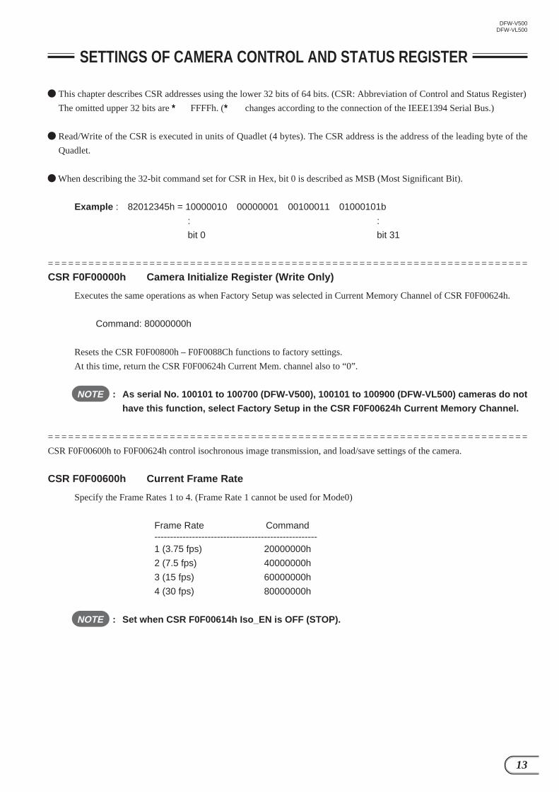
CSR F0F00624h Current Memory Channel
Read out the camera settings (ch1, ch2) memorized by the CSR F0F00618h Memory Save or the factory settings (Factory)
from the memory, and set in the camera.
The Memory Channel that was specified last will be automatically memorized. When the power is turned ON the next
time, the settings memorized in this Memory Channel will be effective.
Channel Command----------------------------------------------------Factory 00000000h
ch1 10000000h
ch2 20000000h
= = = = = = = = = = = = = = = = = = = = = = = = = = = = = = = = = = = = = = = = = = = = = = = = = = = = = = = = = = = = = = = = = = = = = = =
CSR F0F00800h to F0F0088Ch control the various functions of the camera.
CSR F0F00800h Brightness
Adjust the black level of the image.
Command = 820000nnh nn: Adjust in the range of 00h (dark) – FFh (bright).
80h is the standard value.
CSR F0F00804h Auto Exposure
Adjust the exposure compensation of Auto Exposure.
Command = 820000nnh nn: Adjust in the range of 01h (under) – FFh (over).
80h is the standard value.
NOTE : Auto Exposure will not be effective unless either the Shutter, Gain, or Iris is set to Auto.
CSR F0F00808h Sharpness
Adjust the sharpness of the image contour.
Command = 820000nnh nn: Adjust in the range of 00h (soft) – FFh (sharp).
80h is the standard value.

17
DFW-V500DFW-VL500
SETTINGS OF CAMERA CONTROL AND STATUS REGISTER
CSR F0F0080Ch White Balance
Adjust the red and blue gains to properly capture white subjects in color. Two types of automatic adjustment modes are
available.
NOTE : If the CSR F0F00830h Trigger is set to ON or if the CSR F0F0081Ch Shutter setting is less
than 800h, the Auto function cannot be used.
The CSR F0F0088Ch Optical Filter is canceled by this command. (Priority to latter)
(1) Manual adjustment
Command = 820mm0nnh mm: Adjust B-gain in the range of 01h (min) – FFh (max).
nn : Adjust R-gain in the range of 01h (min) – FFh (max).
80h is the standard value.
(2) One-Push Auto White Balance
Perform automatic adjustment when command is received to maintain the white balance at that time.
Execute: Command = 86∗∗∗∗∗∗h ∗∗∗∗∗∗: Undefined
When this operation is complete, the command is read out as 82∗∗∗∗∗∗h (∗∗∗∗∗∗: Undefined).
NOTE : Execute after capturing a white subject lit using the light source used for shooting
over the whole screen at the appropriate exposure. It will take a maximum of 10
seconds to complete automatic adjustment.
Execute again if the light source used for shooting has been changed.
(3) Auto Tracing White Balance
Perform automatic adjustment continuously to trace the white balance according to changes in the shooting
conditions.
ON : Command = 83∗∗∗∗∗∗h ∗∗∗∗∗∗: Undefined
OFF : Set the command of (1) or (2).
NOTE : Operations stop if the exposure is inappropriate.
When the area of the white subject in the screen is small, adjustment accuracy will
drop.
CSR F0F00810h Hue
Adjust the hue of the image.
Command = 820000nnh nn: Adjust in the range of 00h (Skin Tone → Red) – FFh
(Skin Tone → Yellow).
80h is the standard value.
CSR F0F00814h Saturation
Adjust the saturation of the image.
Command = 820000nnh nn: Adjust in the range of 00h (light) – FFh (deep).
80h is the standard value.

18
DFW-V500DFW-VL500
SETTINGS OF CAMERA CONTROL AND STATUS REGISTER
CSR F0F00818h Gamma
Set the gamma characteristics. 80h is the standard value.
Gamma Command----------------------------------------------------ON 82000080h
OFF (1) 82000081h
OFF (2) 82000082h
CSR F0F0081Ch Shutter
Set the exposure time of the electronic shutter. Auto exposure (CCD Iris) can be also set.
(1) Manual adjustment
Command = 82000nnnh nnn: Adjust in the range of 76Ah (long) – A0Fh (short).
800h is the standard value.
5.0 sec ≥ Shutter Speed ≥ 1/30 sec
nnn = 800h – 30 ∗ Shutter Speed (sec)
1/30 sec > Shutter Speed ≥ 1/10,000 sec
nnn = 2573.6 – 15734.3 ∗ Shutter Speed (sec)
Shutter Speed = 1/20,000 sec
nnn = A0Dh
Shutter Speed = 1/50,000 sec
nnn = A0Eh
Shutter Speed = 1/100,000 sec
nnn = A0Fh
NOTE : When nnn < 800h, do not turn ON the Gain, Iris, and White Balance Auto functions.
Remark) The logical exposure time for the setting is as follows.
76Ah ≤ nnn < 800h
Shutter Speed (sec) = (800h – nnn)/30.00732
800h ≤ nnn < A0Ch
Shutter Speed (sec) = (2,007,365 – 780 ∗ nnn)/12,288,000
(2) Auto exposure (CCD Iris)
ON : Command = 83000∗∗∗h ∗∗∗: Undefined
OFF : Set the command of (1).
NOTE : When the CSR F0F00830h Trigger is ON, do not set Auto exposure (CCD Iris) to ON.

19
DFW-V500DFW-VL500
SETTINGS OF CAMERA CONTROL AND STATUS REGISTER
Exposure Time (sec.)
5
2
1
1/2
1/3.75
1/7.5
1/15
1/30
1/50
1/60
1/125
1/250
1/500
1/1,000
1/2,000
1/4,000
1/10,000
1/20,000
1/50,000
1/100,000
Setting Value (Decimal)
1898
1988
2018
2033
2040
2044
2046
2048
2258
2309
2448
2511
2542
2558
2566
2570
2572
2573
2574
2575
Setting Value (Hexadecimal)
76AH
7C4H
7E2H
7F1H
7F8H
7FCH
7FEH
800H
8D2H
905H
990H
9CFH
9EEH
9FEH
A06H
A0AH
A0CH
A0DH
A0EH
A0FH
Setting values of shutter speed for DFW-V500/VL500

20
DFW-V500DFW-VL500
SETTINGS OF CAMERA CONTROL AND STATUS REGISTER
CSR F0F00820h Gain
Adjust the gain of the video signal amplifier. Auto Gain Control can be also set.
(1) Manual adjustment
Command = 820000nnh nn: Adjust in the range of 00h (min) – 12h (max).
00h is the standard value.
(2) Auto Gain Control
ON : Command = 830000∗∗h ∗∗: Undefined
OFF : Set the command of (1).
NOTE : When the CSR F0F0081Ch Shutter setting is less than 800h, do not set Auto Gain
Control to ON.
When the CSR F0F00830h Trigger is ON, do not set Auto Gain Control to ON.
CSR F0F00824h Iris (DFW-VL500 only)
Adjust the iris of the built-in lens. Auto exposure (Lens Iris) can be also set.
(1) Manual adjustment
Command = 82000nnnh nnn: Adjust in the range of 000h (close) – FFFh (open).
(2) Auto exposure (Lens Iris)
ON : Command = 83000∗∗∗h ∗∗∗: Undefined
OFF : Set the command of (1).
NOTE : When the CSR F0F0081Ch Shutter setting is less than 800h, do not set Auto exposure
(Lens Iris) to ON.
When the CSR F0F00830h Trigger is ON, do not set Auto exposure (Lens Iris) to ON.
CSR F0F00828h Focus (DFW-VL500 only)
Adjust the focus of the built-in lens.
Command = 82000nnnh nnn: Adjust in the range of 000h (near) – 1BFh (far).
The value is 100h in factory setting mode.

21
DFW-V500DFW-VL500
SETTINGS OF CAMERA CONTROL AND STATUS REGISTER
CSR F0F00830h Trigger
When inputting a negative polarity signal to the TRIG IN connector at the back of the camera, isochronous transmission of
images for only one frame will be performed.
ON : Command = 82000000h
OFF : Command = 80000000h
NOTE : To set Trigger ON, set the Auto functions of Shutter, Gain, Iris, and White Balance to OFF.
If the CSR F0F00600h – F0F0060Ch settings are not set properly and Iso_EN is not ON at
the same time, no isochronous transmission of images will be executed even when trigger
signals are input.
Do not input a new external trigger signal until isochronous transmission of images ends
after the input of the external trigger signal, otherwise the camera may not operate
correctly.
CSR F0F00880h Zoom (DFW-VL500 only)
Adjust the zoom range of built-in zoom lens.
Command = 82000nnnh nnn: Adjust in the range of 028h (wide) – 598h (tele).
The value is 040h in factory setting mode.
CSR F0F0088Ch Optical Filter
Set the appropriate white balance preset for the main light source.
Lighting Command---------------------------------------------------------------tungsten lamp (3,200 K) 82000000h
day light (5,600 K) 82000001h
NOTE : The CSR F0F0080Ch White Balance value is canceled by this command. (Priority to latter)

22
DFW-V500DFW-VL500
COMMAND SENDING PROCEDURE UNTIL IMAGES ARE DISPLAYED
Obtain the offset address for Node Uniq ID Leaf
420H + 000002H ∗ 4 = 428H
Obtain the offset address for Unit Directory
424H + 000004H ∗ 4 = 434H
(1) Acquiring the camera control register base address
Read out the Configuration ROM and acquire the base address of the camera control register.
The base address of the Configuration ROM is FFFF F0000000H.
Bus Info Block
Root Directory
Offset
400H
404H
408H
40CH
410H
414H
418H
41CH
420H
424H
0 – 7
04
31
20
08
00
00
03
0C
8D
D1
8 – 15
1F
33
FF
00
03
04
08
00
00
00
16 – 23
CE
39
60
46
02
C8
00
83
00
00
24 – 31
D4
34
00
02
8B
0A
46
C0
02
04
Node Uniq ID Leaf
428H
42CH
430H
00
08
00
02
00
05
E7
46
00
33
02
0B
Unit Directory
434H
438H
43CH
440H
00
12
13
D4
03
00
00
00
7D
A0
01
00
AF
2D
01
01
Unit Dependent Info
444H
448H
44CH
450H
00
40
81
82
03
3C
00
00
4F
00
00
00
EA
00
02
05
Obtain the offset address for Unit Dependent Info
440H + 000001H ∗ 4 = 444H
Obtain the offset address for Camera Control register
FFFFF0000000H + 3C0000H ∗ 4 = FFFFF0F00000H
The base address of the control register of this camera is FFFF F0F00000H.

23
DFW-V500DFW-VL500
COMMAND SENDING PROCEDURE UNTIL IMAGES ARE DISPLAYED
Address
F0F00100H
Action
Read
Data
80000000H
(2) Acquiring the format/mode/frame rate
a) Check available formats
Refer to the Inquiry register for video format and check the available formats.
As bit 0 is set, it means that Format0 is available.
b) Check available video modes
Refer to Inquiry register for video mode, and check which video mode in Format0 is available.
As bits 0, 1, 2, and 3 are set, it means that Mode0, Mode1, Mode2, and Mode3 are available.
c) Check available frame rates (Example: Mode3)
As bits 1, 2, 3, and 4 are set, it means that 3.75 fps, 7.5 fps, 15 fps, and 30 fps are available.
Address
F0F00180H
Action
Read
Data
F0000000H
Address
F0F0020CH
Action
Read
Data
78000000H
Address
F0F00614H
Action
Write
Data
00000000H ISO Enable OFF
Address
F0F00600H
F0F00604H
F0F00608H
F0F0060CH
F0F00614H
Action
Write
Write
Write
Write
Write
Data
80000000H
60000000H
00000000H
02000000H
80000000H
Frame Rate = 30 fps
Video Mode = 3
Video Format = 0
ISO ch = 0, Speed = 400M bps
ISO Enable ON
To stop the video, set the ISO Enable bit to 0.
(3) Video transmission start command
When the following values are set for Status and Control registers for the camera, the camera starts video transmission.
(Example: Video Format = 0, Video Mode = 3, Frame Rate = 30 fps, ISO Speed = 400M bps)
24
DFW-V500DFW-VL500
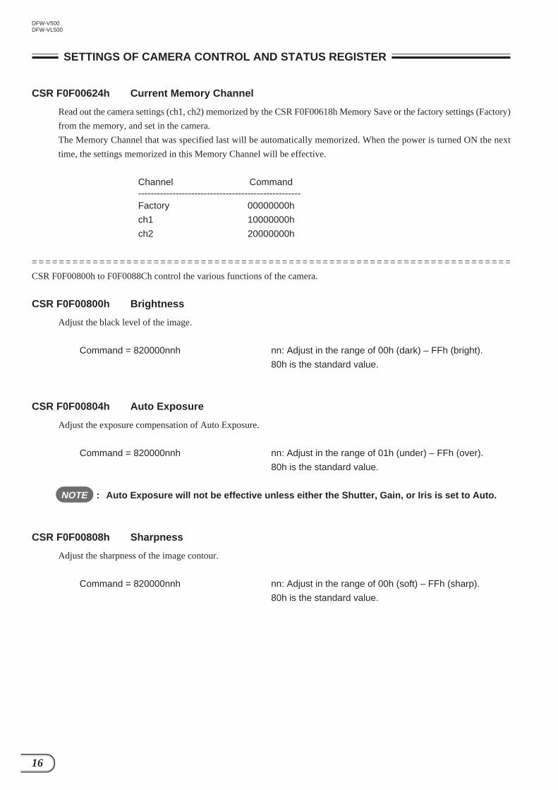
The DFW-V500/VL500 operates synchronously with 33.33 ms cycle internal pulses called VD. VDs are reference signals inside
the camera and cannot be observed from outside the camera.
Even if commands are set to the CSR of the camera, it does not mean that they become effective the instant they have been
written. They become effective after the VD period set to the CSR has been completed and the next VD pulse is generated as
shown in the following figure. The command settings are set for video signals by the Isochronous output after that. (The timing at
which the command settings become effective may be delayed according to the internal state of the camera.)
When operating at a low frame rate such as 7.5 frame/s even if the transmission time of one frame exceeds one VD, and the CSR
settings are changed during transmission, the command settings will not be set to the video signals until the frame currently being
output is complete.
COMMAND SETTING AND OPERATION TIMING
When Frame Rate is 7.5 Frame/s(When other than 30 frame/s is selected, changes in settings are made effective for the output
after the isochronous output before or while setting the command has been completed)
When Frame Rate is 30 Frame/s
1 V = 33.33 msCommand settings are set to isochronousoutput after setting becomes effective
Image Readout
VD
Isochronous
Set command to CSR in this period
Changes made in settings are not effectivefor isochronous output in this period
Setting becomes effective innext VD period (or the next)
VD
Isochronous
Set command to CSR in this period
Image Readout
Changes made in settings are not effectivefor isochronous output in this period
Setting becomes effective innext VD period (or the next)
Image Readout(Setting becomes effective)
Command settings are set to isochronousoutput after setting becomes effective

25
DFW-V500DFW-VL500
COMMAND SETTING AND OPERATION TIMING
Isochronous Transmission Start/Stop command and actual operation timingAs shown in the following figure, it takes at least about 1 V for the actual isochronous transmission of image data to start or
stop after the Isochronous Start/Stop command (CSR F0F00614h: ISO_EN) has been set to the CSR of the camera. (VDs are
the reference signals inside the camera and cannot be observed from outside the camera.)
Isochronous transmission start/stop is executed in units of frames. Isochronous transmission will not start/stop before one
image output ends. This means that if a low frame rate at which the transmission of one image takes a long time is selected, the
time taken for executing Isochronous Stop will be long.
When Isochronous Start
When Isochronous Stop (30 Frame/s)
When Isochronous Stop (7.5 Frame/s)
VD
Isochronous
1 V = 33.33 ms
Set Iso Start in this period
Image Readout
Isochronous output starts
Isochronous output is prepared
VD
Isochronous
1 V = 33.33 ms
Set Iso Stop in this period
Image Readout
Isochronous output stoppedfrom this period
Isochronous output stop is prepared
Set Iso Stop in this periodIsochronous output in this period cannot be stoppedbecause image data of one frame is still transmitting
VD
IsochronousIsochronous output stopped from this period
Isochronous output stop is prepared

26
DFW-V500DFW-VL500
COMMAND SETTING AND OPERATION TIMING
If Shutter (CSR F0F0081Ch) is set to the extended exposing mode, command execution may be delayed for the exposure time
at maximum in addition to the previous delay for Isochronous Start.
When Isochronous Start (Exposure Time: 4 Frames)
VD
SG
Isochronous
Exposure of 4 Frames
Set Iso Start in this period
Image Readout
Isochronous output starts from this period
Isochronous output is prepared
VD
SG
Isochronous
Exposure of 4 Frames
Set Iso Start in this period
Isochronous output startsfrom this period
Exposure of 4 Frames
Isochronous output is prepared
Image ReadoutImage cannot be still read out

27
DFW-V500DFW-VL500
If Shutter (CSR F0F0081Ch) is set to the extended exposing mode, command execution may also be delayed same as the
previous command for Isochronous Stop.
When Isochronous Stop (Exposure Time: 4 Frames)
COMMAND SETTING AND OPERATION TIMING
VD
SG
Isochronous
Exposure of 4 Frames
Set Iso Stop in this period
Isochronous output in this period cannot be stopped
Isochronous outputstop is prepared Isochronous output stop is made
effective from this period
Image Readout Image Readout
VD
SG
Isochronous
Exposure of 4 Frames
Set Iso Stop in this period
Isochronous outputstop is prepared Isochronous output stop is made
effective from this period
Image ReadoutImage is not read out

28
DFW-V500DFW-VL500
COMMAND SETTING AND OPERATION TIMING
One Shot CMD and actual operation timingAs shown in the following figure, it takes at least about 1 V for the actual isochronous transmission to start after the One Shot
command (CSR F0F0061Ch) has been set to the CSR of the camera.
(VDs are the reference signals inside the camera and cannot be observed from outside the camera.)
If Shutter (CSR F0F0081Ch) is set to the extended exposing mode, isochronous transmission start may be delayed for the
exposure time at maximum in addition to the previous delay.
When One Shot (Exposure Time: 4 Frames)
If Shutter (CSR F0F0081Ch) is set to the extended exposing mode, image data for which exposure has been started before One
Shot command is set may be output.
VD
Isochronous
1 V = 33.33 ms Exposure
Set One Shot in this period
Image Readout Isochronous transmissionfor only one frame starts
Isochronous output is prepared
VD
SG
Isochronous
Exposure of 4 Frames
Set One Shot in this periodIsochronous output is prepared
Exposure of 4 Frames
Image ReadoutImage cannot be still read out
VD
SG
Isochronous
Exposure of 4 Frames
Set One Shot in this periodIsochronous output is prepared
Image Readout

29
DFW-V500DFW-VL500
Do not set a new One Shot command until isochronous transmission of one frame image data ends after the One Shot
command has been set.
COMMAND SETTING AND OPERATION TIMING
VD
SG
Isochronous
Exposure of 3 Frames
Set One Shot in this periodIsochronous output is prepared
Image ReadoutIsochronous output ofone frame ends
New One Shot command setting is prohibited during this period
When Frame Rate is 7.5 Frame/s and Exposure Time is 3 Frames
30
DFW-V500DFW-VL500
COMMAND SETTING AND OPERATION TIMING
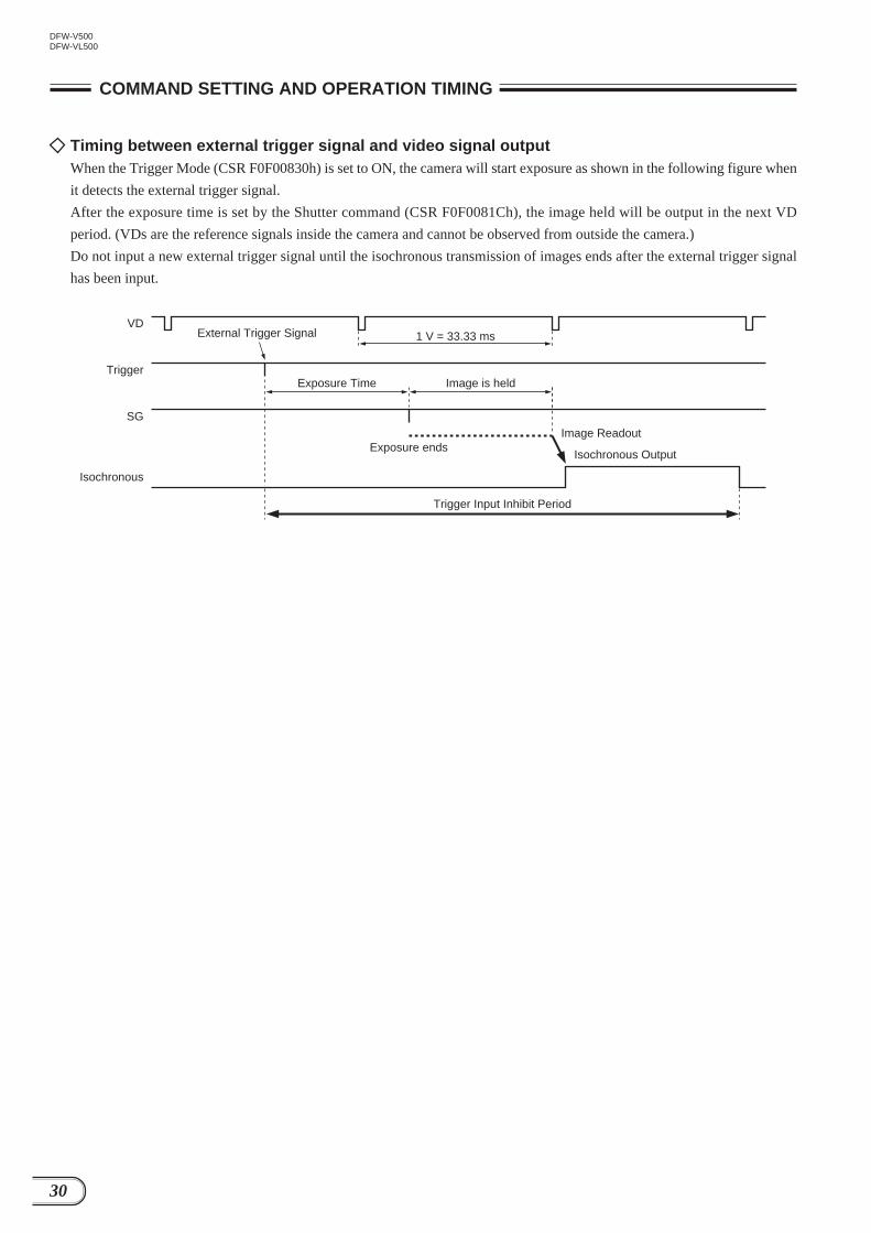
Timing between external trigger signal and video signal outputWhen the Trigger Mode (CSR F0F00830h) is set to ON, the camera will start exposure as shown in the following figure when
it detects the external trigger signal.
After the exposure time is set by the Shutter command (CSR F0F0081Ch), the image held will be output in the next VD
period. (VDs are the reference signals inside the camera and cannot be observed from outside the camera.)
Do not input a new external trigger signal until the isochronous transmission of images ends after the external trigger signal
has been input.
VD
Trigger
Isochronous
SG
1 V = 33.33 ms
Exposure Time Image is held
Image Readout
Isochronous OutputExposure ends
Trigger Input Inhibit Period
External Trigger Signal

31
DFW-V500DFW-VL500
COMMAND SETTING AND OPERATION TIMING
When Frame Rate is 30 Frame/s
When Frame Rate is 7.5 Frame/s
Trigger Mode command and actual operation timingIt takes at least about 1 V for external trigger signals to be received (Trigger Mode) after the Trigger ON command has been
set to the CSR (F0F00830h) of the camera during the isochronous output of the moving image. (VDs are the reference signals
inside the camera and cannot be observed from outside the camera.)
External trigger signal inputs during the isochronous transmission will not be accepted. Input external trigger signals after the
isochronous transmission completes.
VD
SG
Isochronous
Set Trigger ON in this period
Image ReadoutIsochronous output ends
Image Readout
1 V = 33.33 ms
External trigger signal can beinput from here
VD
SG
Isochronous
Set Trigger ON in this period
Image Readout Image Readout
External triggersignal can beinput from here
VD
SG
Isochronous
Set Trigger ON in this period
Image Readout
External trigger signal can beinput from here

32
DFW-V500DFW-VL500
COMMAND SETTING AND OPERATION TIMING
When Trigger OFF is Set during Image Output at Low Frame Rate
As shown in the following figure, it takes at least about 1 V for the normal transmission of moving images to start after the
Trigger OFF command has been set to the CSR (F0F00830h) of the camera. (VDs are the reference signals inside the camera
and cannot be observed from outside the camera.)
When Trigger OFF is set during extended exposing mode, exposure is discontinued and re-exposure is started in the normal
moving image mode.
When Trigger OFF is Set during Extended Exposing Mode
When low frame rate at which the transmission of one image takes a long time is selected, isochronous transmission may not
have been completed when Trigger OFF is executed. In this case, output of normal moving images will start after transmission
ends.
VD
SG
Isochronous
Set Trigger OFF in this period
Image ReadoutIsochronous moving imageoutput starts
1 V = 33.33 ms Exposure for moving images starts
Isochronous moving image output is prepared
VD
SG
Isochronous
Set Trigger OFF in this period
Image Readout by External Trigger Signal Isochronous moving imageoutput starts
Isochronous Output by External Trigger Signal
Set Trigger OFF in this period
This exposure issuspended temporarily
VD
Trigger
Isochronous
Exposure Time Exposure
Image Readout byExternal Trigger Signal
Restart of Exposure
Isochronous Output by External Trigger Signal
SG
Isochronous moving imageoutput starts

33
DFW-V500DFW-VL500
SHUTTER
When exposure time is 1 frame or shorterVDs are generated continuously inside the camera, and the video signals synchronize with them and are output by isochronous
transmission. (VDs are the reference signals inside the camera and cannot be observed from outside the camera.)
If a frame rate lower than 30 frame/s is selected at CSR F0F00600h Current Frame Rate, the image data output at the actual 30
frame/s will be interpolated in unit frame and transmitted at the designated frame rate.
When Frame Rate is 30 Frame/s
When Frame Rate is 15 Frame/s
When Frame Rate is 7.5 Frame/s
VD
SUBExposure
Isochronous
Exposure
Video SignalOutput
Video SignalOutput
Video SignalOutput
Video SignalOutput
Video SignalOutput
Exposure Exposure Exposure
SG
Image Readout Image Readout Image Readout Image Readout Image Readout
VD
SUBExposure
Isochronous
Exposure
Video SignalOutput
Video Signal OutputVideo Signal Output
Exposure Exposure Exposure
SG
Image Readout Image Readout Image Readout
VD
SUBExposure
Isochronous
Exposure
Video SignalOutput
Video Signal Output
Exposure Exposure Exposure
SG
Image Readout Image Readout

34
DFW-V500DFW-VL500
SHUTTER
The timing at which the video signal is output by isochronous transmission is as follows.
Because the packet serving as the reference of the timing above 1394 bus and camera VD are asynchronous and the camera
cannot dominate the bus 100% when other equipments are connected to the 1394 bus, the following output timing will vary.
Video Mode
0
1
2
3
A [ms]
—
3.1
3.1
3.1
2.3
2.3
2.3
2.3
1.9
1.9
1.9
1.9
1.9
1.9
1.9
1.9
B [ms]
—
120
60
30
240
120
60
30
240
120
60
30
240
120
60
30
Frame Rate
3.75
7.5
15
30
3.75
7.5
15
30
3.75
7.5
15
30
3.75
7.5
15
30
C [ms]
—
13.3
6.7
3.3
26.6
13.3
6.7
3.3
26.6
13.3
6.7
3.3
26.6
13.3
6.7
3.3
VD
Isochronous
SUB
SG
Video Signal OutputCA B

35
DFW-V500DFW-VL500
SHUTTER
When exposure time is over 1 frameEven if the exposure time over 1 frame (1/30 sec) is set, the time (A period) to the output of the video signal from VD at the
time exposure completes and the time required (B period) for isochronous transmitting video signal of one frame will be the
same as the previous section. However, as no images are output during the exposure time, the actual frame rate may be lower
than the value specified at the CSR F0F00600h Current Frame Rate.
When Exposure Time is 3 Frames and Frame Rate is 30 Frame/s
When Exposure Time is 3 Frames and Frame Rate is 15 Frame/s
When Exposure Time is 3 Frames and Frame Rate is 7.5 Frame/s
Isochronous
Video Signal Output(Output at every three frames, therefore frame rate is 10 frame/s)
VD
SGExposure Time
Image ReadoutImage Readout
Isochronous
Video Signal Output(Output at every three frames, therefore frame rate is 10 frame/s)
VD
SGExposure Time
Image ReadoutImage Readout
Isochronous
Video Signal Output(Output at every six frames, therefore frame rate is 5 frame/s)
VD
SGExposure Time
Image ReadoutIneffectiveReadout Image Readout

36
DFW-V500DFW-VL500
The DFWA-400 host adapter card is an IEEE1394 serial bus interface card. You can install this card in the PCI bus slot in IBM
PC/AT compatible computer.
Features
PCI interface
Complies with PCI Short Card (5 V, 32-bit) standard
Complies with PCI Local Bus Rev 2.1 standard
Supports the PCI Bus Master function
Supports the PCI Bus DMA transfer function
IEEE1394 interface
High-speed data transfer rate: 100M/200M/400M bits/second
Supports both asynchronous transfer and isochronous transfer
Supports the isochronous cycle master function
Provides three 6-pin connectors to connect the camera module
Recommended Specifications for Personal Computer (PC)
Processor : Pentium 500 MHz or more
Free main memory : 40 MB or more
Video memory : 8 MB or more
Display mode : Can display 1,280 × 1,024 (true color)
Expansion slot : With 1 × PCI bus
OS : Windows* 98 or Windows* NT4.0
NOTE : For details on the peripherals and the computer to which you are connecting the DFWA-400
card, see the respective manuals.
* “Windows” is a trademark of Microsoft Corporation, registered in the U.S.A. and other countries.
Note) Zenkuman (indicated on the card) is a registered trademark of Technoscope, Co., Ltd.
HOST ADAPTER CARD DFWA-400

37
DFW-V500DFW-VL500
Specifications
Board configuration
CN4
CN3
CN2
CN1
PCI Card Edge
CN1, 2, 3 : IEEE1394 6-pin connector
CN4 : External power supply connector
PCI card edge : 124-pin PCI local bus connector
Pin assignment
IEEE1394 6-pin connector External power supply connector
Pin No. Signal
1 3 5
2 4 61 2 3 4
1
2
3
4
5
6
VP
VG
TPB*
TPB
TPA*
TPA
Pin No. Signal
1
2
3
4
+12 V
GND
GND
+5 V (Not used)
Common to CN1, CN2, and CN3.
External power supply connector
The IEEE1394 bus power supplied from PCI bus is about
0.5 A. If you need more power, use a separate power
branch cable and connect the FDD power socket to this
connector. You can get up to 1.5 A power through this
connector.
(Example: Mounted connector 176153-4 (AMP))
: IEEE1394-1995 standard
: PCI Lynx
: 3
: +5 V, +12 V
: 10 to 35°C (no condensation)
: 107 × 138 mm
: IEEE1394 6-pin connector
: 176153-4 (AMP) or equivalent
: Setup disk (1), Operating Instructions (1)
I/F standard
Chip set
Number of ports
Supply voltage
Operating temperature
Dimensions
Connectors
IEEE1394
External power supply
Accessories
HOST ADAPTER CARD DFWA-400

38
DFW-V500DFW-VL500
Installing the Host Adapter Card
NOTE : Before installing the host adapter card in the computer, be sure to install the setup disk
software provided. Otherwise the computer may freeze when started.
(1) After starting the computer, insert the floppy disk provided into the floppy disk drive.
(2) Open “My Computer” and select the floppy disk drive.
(3) Open Readme.txt.
(4) While reading Readme.txt, install the software.
(5) After installing, eject the floppy disk, shut down Windows, and turn off the power of the computer.
(6) Unplug the computer power cable from the wall outlet.
NOTE : Make sure you unplug the computer power cable from the wall outlet. Installing the host
adapter card without unplugging the power cable may damage both the computer and the
card.
(7) Open the computer case and remove the PCI bus slot cover.
(8) Securely insert the host adapter card into the PCI bus slot and affix in place it with the screw.
NOTE : When you install the card, hold the top part of the card. Make sure that the PCI card edge is
parallel to the slot. Insert the card into the slot as straight in as possible.
You may need to apply some force when installing the card into the slot. Insert the card
until the card snaps into the slot.
If you are having difficulty inserting the card properly, remove it from the slot and try
again.
Some computers do not require a screw to affix the card in place.
(9) Install the computer case.
HOST ADAPTER CARD DFWA-400

39
DFW-V500DFW-VL500
Setup of the Driver
Precautions(1) Precautions on installing the DFWA-400 in the PC using Windows 98
The DFWA-400 does not run with the standard Windows 98 IEEE1394 driver.
If the DFWA-400 is run with the standard driver, the PC may crash. To prevent this, before installing the DFWA-400
in the PC, make sure to install the DFWA-400 driver.
To ensure this, be sure to perform the following procedure in Setting Up the Driver (for Windows 98).
Operations may not be performed normally if the board is installed without following the procedure below.
(2) Precautions on software provided
The driver and demonstration software included in the floppy disk (hereafter referred to as FD) provided are
compatible only for Windows 98 and Windows NT4.0. In any other operating system, these will not operate.
Use of the driver and demonstration software may cause malfunction or damage to user’s hardware and software.
Sony Corporation is not liable for any of such damages.
The demonstration software can be used for both Windows 98 and Windows NT4.0.
The demonstration software can operate only with the Sony IEEE1394 digital camera DFW and XCD series*.
It will not operate with other Sony products such as the Digital Handycam.
During use with the DFW-V300, the demonstration software may not operate normally in some video modes.
If the demonstration software does not operate normally during use, shut down the demonstration software,
disconnect and reconnect the camera cable, and start the demonstration software again.
Display color modes which can be displayed for the demonstration software are 24 bits and 32 bits. Other color
modes are not supported.
If the PC performance (CPU clock, memory installed, etc.) is insufficient, the demonstration software may not
operate normally.
* The Sony IEEE1394 digital camera DFW and XCD series include the DFW-V300, DFW-V500, DFW-VL500,
DFW-SX900, DFW-X700, XCD-SX900, and XCD-X700. (The CCM-DS250 does not operate with this software.)
HOST ADAPTER CARD DFWA-400

40
DFW-V500DFW-VL500
Setting up the driver
<For Windows 98>
(1) Turn on the PC power without installing the DFWA-400 in the PC, and start Windows.
(2) Start \Setup98\Setup recorded in the FD.
(3) After ejecting the FD, quit Windows, and turn off the PC power.
(4) Unplug from wall outlet.
(5) Install the DFWA-400 in an expansion PCI bus slot.
(6) Turn on the PC power, and start Windows.
(7) The DFWA-400 will be identified by the Windows Plug and Play function. For the driver used, select
\Setup98\Driver\SonyPFW.inf in the FD.
(8) After installing the driver, eject the FD and restart the PC according to the message on screen.
<For Windows NT4.0>
(1) Turn on the PC power, and start Windows.
(2) Execute \SetupNT\Setup.exe in the FD. (The installer starts automatically.)
(3) After installing the software, select “No, I will restart my computer later”.
(4) After ejecting the FD, quit Windows, and turn off the PC power.
(5) Unplug from wall outlet.
(6) Install the DFWA-400 in an expansion PCI bus slot.
(7) Turn on the PC power, and start Windows.
This completes the setup of the driver.
HOST ADAPTER CARD DFWA-400
Setting up the demonstration softwareCopy \Demo\Dfwnt.exe in the FD to the desired directory for both Windows 98 and Windows NT4.0.

Sony reserves the right to change specifications of the products and discontinue products without notice.

Sales Office :
Japan http://www.sony.co.jp/ISP/
Sony Corporation (JAPAN)4-14-1, Asahi-cho, Atsugi-shi, Kanagawa-ken,243-0014 JapanTel: +81-46-230-5873 Fax: +81-46-230-6243
USA http://www.sony.com/videocameras
Sony Electronics Inc.HQ1 Sony Drive, Park Ridge, NJ 07656Tel: +1-800-686-7669
CanadaSony of Canada Ltd.
115 Gordon Baker Rd, Toronto, Ontario M2H 3R6Tel: +1-416-499-1414 Fax: +1-416-497-1774
Europe http://www.pro.sony-europe.com/isp/
Sony Broadcast & ProfessionalHQSchipholweg 275, 1171 PK Badhoevedorp, The NetherlandsTel: +31-20-44-99-351 Fax: +31-20-44-99-333
GermanyHugo-Eckener-Str. 20, D-50829 KolnTel: +49-221-5378-923 Fax: +49-221-537-491
France16-26, rue Morel 92110 ClichyTel: +33-1-55-90-41-58 Fax: +33-1-55-90-42-20
UKThe Heights, Brooklands, Weybridge, Surrey KT13 0XWTel: +44-990-331122 Fax: +44-1932-817011
NordicPer Albin Hanssons vag 20 S-214 32 Malmo SwedenTel: +46-40-190-800 Fax: +46-40-190-450
ItalyVia Galileo Galilei 40 l-20092 Cinisello Balsamo, MilanoTel: +39-02-618-38-431 Fax: +39-02-618-38-402
© 2001 Sony Corporation. All rights reserved.Reproduction in whole or in part without written permission is prohibited.All specifications subject to change without notice. 01A
CCD COLOR DIGITALCAMERA MODULE
DFW-V500DFW-VL500