Embed Size (px)
Citation preview

GEK-104145
TECHNICAL MANUAL FOR
FIRE PUMP AC MOTOR CONTROLLER SIZE FIVE REDUCED-VOLTAGE
AUTOTRANSFORMER TYPE
GENERAL ELECTRIC COMPANY CONTRACT NUMBER N00406-93-M-N290
MARCH 1994

AC Motor Controller GEK-104145
FOREWORD
This manual provides installation, operating, and maintenance instructions for GE’s IC5130 size five, reduced-voltage, autotransformer ac motor controllers for fire pump application onboard ship. This manual consists of the following sections:
Table of Contents List of Figures List of Tables Safety Summary Chapter 1 - Safety Precautions and General Information Chapter 2 - Operation Chapter 3 - Functional Description Chapter 4 - Scheduled Maintenance Chapter 5 - Troubleshooting Chapter 6 - Corrective Maintenance Chapter 7 - Parts List Chapter 8 - Installation
This manual was prepared under commercial specifications for contract N00406-93-M-N290. The contents meet the requirements of Technical Manual Contract Requirement (TMCR) No. NDMS-930068-000.
Foreword-l/(Foreword-2 blank)

AC Motor Controller GEK-104145
TABLE OF CONTENTS
Section/Subiect Page
CHAPTER 1. SAFETY PRECAUTIONS AND GENERAL INFORMATION
l-l. Safety Precautions ................ l-l l-1.1. Warning Statements .............. l-l 1-1.2. Caution Statements .............. l-l 1-1.3. Safety Summary ................ l-2 1-2. Introduction .................... 1 - 1 l-3. Equipment Description ............. l-l 1-3.1. Identification .................. l-l l-3.2. Equipment Specifications ........... l-l l-3.3. Equipment Application ............ l-2
CHAPTER 2. OPERATION
2-l. Introduction .................... 2-l 2-2. Operating Procedures .............. 2-l
CHAPTER 3. FUNCTIONAL DESCRIPTION
3-l. Introduction .................... 3-l 3-2. Controller Switching Circuits ......... 3-l 3-2.1. Contactor Operation .............. 3-l 3-3. Overload Protection ............... 3-l 3-3.1. IC5182 Multipole Relay ........... 3-2 3-3.2. IC5882 Temperature-compensated Thermal
Overload Relay .................. 3-2 3-4. Motor Starting .................. 3-2 3-5. Low-voltage Operation ............. 3-2 3-5.1. Low-voltage Protection ............ 3-2 3-5.1.1. Low-voltage Protection with Pilot Device 3-2 3-5.2. Low-voltage Release .............. 3-3
CHAPTER 4. SCHEDULED MAINTENANCE
4-l. Introduction .................... 4-l 4-2. Safety Precautions ................ 4-l 4-2.1. Servicing Live Equipment .......... 4-l 4-3. Preventive Maintenance Schedule ....... 4-l 4-4. Required Tools and Test Equipment ..... 4-2 4-5. Controller Maintenance ............. 4-2 4-5.1. Enclosure Exterior ............... 4-2 4-5.2. Enclosure Interior ............... 4-2 4-5.3. Wiring and Connections ........... 4-3 4-5.4. Lights and Fuses ................ 4-3 4-5.5. Contactors .................... 4-3
Section/Subiect m
4-5.5.1. Contact Wear ................. 4-4 4-5.6. Insulation Resistance Test ........ 4-4 4-5.7. Online Check .................. 4-4 4-6. Planned Overhaul Maintenance ........ 4-4
CHAPTER 5. TROUBLESHOOTING
5-l. Introduction .................... 5-l 5-2. Required Tools and Test Equipment ..... 5-l 5-3. Troubleshooting Procedures .......... 5-l
CHAPTER 6. CORRECTIVE MAINTENANCE
6-l. Introduction .................... 6-l
I. Adjustments and Alignments 6-2. Relay Trip Adjustments ............. 6-l 6-2.1. Timing Relay (Agastat Type) ........ 6-l 6-2.2. IC5882 Thermal Overload Relay ...... 6-2
II. Repair 6-3. Controller Repair and Replacement
Procedures ...................... 6-2 6-3.1. IC5 181 Contactors ............... 6-2 6-3.1.1. Coil Replacement, IC5181C105
Contactor ....................... 6-2 6-3.1.2. Coil Replacement, IC5181C104
Contactor ....................... 6-3 6-3.1.3. Return Spring Replacement ........ 6-4 6-3.1.4. Contact Assembly .............. 6-5 6-3.1.5. Auxiliary Contacts .............. 6-5 6-3.2. IC5 182 Multipole Relay ........... 6-6 6-3.2.1. Coil Replacement .............. 6-6 6-3.2.2. Return Spring Replacement ........ 6-7 6-3.2.3. Auxiliary Contacts .............. 6-7 6-3.3. Fuse Replacement ............... 6-7 6-3.4. Indicator Light Replacement ......... 6-7 6-3.5. Pushbutton Replacement ........... 6-8 6-3.6. Relay, Switch, and Transformer
Replacement .................... 6-8
CHAPTER 7. PARTS LIST
7-l. Introduction .................... 7-1 7-2. Using the Parts List ............... 7-l
GEK-104145 AC Motor Controller
TABLE OF CONTENTS - Continued
SectiodSubiect Pane Section/Subiect &lg
CHAPTER 8. INSTALLATION 8-5. Installation ..................... 8-3 8-5.1. Preparation ................... 8-3
8-l. Introduction .................... 8- 1 8-5.2. Mounting .................... 8-3 8-2. Receiving and Handling ............. 8-l 8-5.3. Incoming Cabling and Wiring ........ 8-3 8-2.1. Removing the Lifting Angle ......... 8-l 8-6. Inspection and Preenergizing Procedures ... 8-3 8-3. Unpacking ..................... 8-l 8-7. Turn On and Preliminary Tests ........ 8-4 8-4. Storage ....................... 8-l 8-8. Installation Verification Test .......... 8-4
ii

AC Motor Controller GEK-104145
LIST OF FIGURES
Fiqure Pane Fiqure Pane
l-l. Typical Controller . . . . . . . . . . . . . . . . 1-O Z-l. Operator Panel Controls and Indicators . . . 2-2 3-l. Reduced-voltage Type Controller Unit . . . . 3-1 3-2. Simplified Low-voltage Protection Circuit . . 3-2 3-3. LVP Circuit with Pilot Device . . . . . . . . . 3-2 3-4. Simplified Low-voltage Release Circuit . . . 3-3 4-l. Auxiliary Contact Alignment, ICS 181
Contactors . . . . , . . . . . . . . . . . . . . . . . 4-3 5-l. Controller Schematic Diagram (Part Number
229B3 195G.lS2) . . . . . . . . . . . . . . . . 5-5 6-l. Agastat Timing Relay . . . . . . . . . . . . . . 6-l 6-2. IC5882 Thermal Overload Relay . . . . . . . 6-2
6-3. IC5181C105 Contactor . . . . . . . . . . . . . 6-3 6-4. IC5 181C105 Contactor, Exploded View . . . 6-3 6-5. IC5181C104 Contactor . . . . . . . . . . . . . 6-4 6-6. IC5181C104 Contactor, Exploded View . . . 6-4 6-7. Contactor Auxiliary Contacts, Exploded
View . . . . . . . . . . . . . . . . . . . . . . . . . 6-5 6-8. IC5182 Multipole Relay . . . . . . . . . . . . . 6-6 6-9. IC5182 Multipole Relay, Exploded View . . 6-6 6-10. Indicator Light Assembly . . . . . . . . . . . 6-7 7-l. Controller Parts Location . . . . . . . . . . . . 7-3 8-l. Controller Outline Drawing and Mounting
Details . . . . . . . . . . . . . . . . . . . . . . . . 8-2
. . . 111

GEK-104145 AC Motor Controller
LIST OF TABLES
Table Pane Table m
2-1. Operating Controls and Indicators ....... 2-l 5-2. Controller Trouble Analysis Chart ...... 5-2 2-2. Operating Procedures .............. 2-3 6-l. Autotransformer Data .............. 6-8 4-1. Preventive Maintenance Schedule ....... 4-2 6-2. Current Transformer Data ............ 6-8 4-2. Required Maintenance Tools, Materials, 7-l. Parts List ...................... 7-l
and Test Equipment ................ 4-2 7-2. List of Parts Manufacturers ........... 7-4 5-1. Required Troubleshooting Tools, Materials, 7-3. Overload Heater Part Numbers ........ 7-4
and Test Equipment ................ 5-l 8-l. External Wiring Connections .......... 8-3
iv
AC Motor Controller GEK-104145
SAFETY SUMMARY
GENERAL PRECAUTIONS
The following are general safety precautions not related to any specific procedure, so they do not appear else- where in this manual. These are recommended precau- tions that personnel must fully understand and apply during all phases of operation and maintenance of the equipment.
Keep Away From Live Circuits. Personnel must at all times observe all safety regulations. It is crucial that all power supplies be turned off before replacing components or making adjustments inside the equipment. Note that dangerous conditions may still exist when the power is in the “off” position, because capacitors sometimes retain charges. To avoid casualties when working on the equip- ment, always remove power, then discharge and ground a circuit before touching it.
1 WARNING 1
High voltages capable of causing death are used in this equipment. Use extreme caution when servicing either the power supplies or their switching components.
Do Not Service or Adjust When Alone. Under no circumstances should any person reach into or enter the enclosure for the purpose of servicing or adjusting the equipment, unless another person capable of rendering aid is present.
Resuscitation. Personnel working with or near high voltages should know and be able to apply approved methods of resuscitation. Such information can be ob- tained from the Bureau of Medicine and Surgery.
SPECIFIC PRECAUTIONS
The precautions listed below are also located in the text of this manual to alert and guide personnel when a specific procedure or instruction contains a potential danger to them or to thk equipment. These precautions precede the specific procedure or instruction.
,
Disconnect all power supplies before perform- ing any maintenance, adjustments, servicing, parts replacements, or other act requiring physical contact with the electrical working components or wiring of this equipment. (Pag- es 4-1 and 6-l)
WARNING I
Use only one hand when servicing live equip- ment. This prevents an accidental current path being created through the body from one hand to the other. (Page 4-l)
1 WARNING 1
Before any maintenance, adjustments, ser- vicing, parts replacements, or other act is performed requiring physical contact with the electrical working components or wiring of this equipment, disconnect all power supplies, then discharge and ground the equipment. (Page 5-1)
/ WARNING 1
Before handling and connecting any power cables to the equipment, ensure that all power supplies are turned off. Then check voltage levels on the wiring to ensure that the wiring is not carrying hazardous voltages. (Page 8-3)
V

GEK-ld4145 AC Motor Controller
Short out all meter terminals and disconnect diodes and other electronic components that might be damaged by application of insulation resistance measuring vohage before perform- ing the insulation resistance test. (Page 4-4)
Do not under any circumstances manually trip a relay by forcing the trip mechanism. This will deform the mechanism, permanently disturbing calibration. (Page 6-1)
1 CAUTION
Before moving equipment, ensure that the doors are closed and their thumb screws are fastened. (Page S-l)
Remove all cartons and other miscellaneous material packed inside units before energizing any heaters. (Page 83)
To avoid damaging the timing relay needle or orifice, turn the adjusting screw only a frac- tion of a revolution before each timing check. (Page 6-l)
vi


AC Motor Controller GEK-104145
CHAPTER 1
SAFETY PRECAUTIONS AND GENERAL INFORMATION
I-l. SAFETY PRECAUTIONS
AC motor controllers use hazardous voltages. This manual includes warning and caution statements that must be observed to ensure the safety of personnel and equipment. It is important to fully understand the warnings, cautions, and instructions in this manual before operating or maintaining this equipment.
l-l .I . Warning Statements
A warning statement alerts personnel to a step of a procedure that, if not strictly followed, could seriously injure or kill someone.
l-l .2. Caution Statements
A caution statement alerts personnel to a step of a proce- dure that, if not strictly followed, could damage or destroy equipment.
1-l .3. Safety Summary
For a listing of all warnings and caution statements used in this manual, refer to the Safety Summary located in the front matter.
1-2. INTRODUCTION
This manual provides installation, operating, and mainte- nance instructions for GE’s IC5130B38 ac motor control- lers. This equipment consists of 16 size 5 magnetic type controllers, as shown in Figure l-l.
l-3. EQUIPMENT DESCRIPTION
1-3.1. Identification
The motor controller configuration is identified by GE catalog (part) number 229B3195GlS2. This part number is located on the controller nameplate, and is used to identify the controller when ordering replacement parts.
The first section of the part number, 229B3 195, identifies the basic controller and is also the engineering drawing number. The Gl digits indicate the group number from the material list (on the engineering drawing), represent- ing material variations in the equipment. The S2 digits indicate the engineering drawing sheet number (sheet 2) that contains the connection diagram. (Engineering drawings are not included in this manual.)
I-3.2. Equipment Specifications
The equipment meets the requirements of Military Specification MIL-C-2212F for ac motor controllers for Naval Shipboard use, with the exception of AMP wire terminals and current transformers 1CT and 2CT. The AMP wire terminals are approved by NAVSEA Letter Ser. 055/144 dated 6/8/93. Current transformers 1CT and 2CT are approved by NAVSEA Letter Ser. 05E2/296 dated 6124193.
The controller units have the following specifications:
Certification data drawing: 305A3195
Size: 5
Input power rating: 440 V, 3-phase, 60 Hz
Duty: Continuous
Type: Reduced voltage (autotransformer), single speed, non-reversing
Control: Local and remote
Motor rating: 200 hp maximum, 270 A maximum
Ambient temperature: 50 “C! (122 “F)
Weight: 1260 lbs calculated, unboxed
Enclosure: Dripproof
l-l

GEK-104145 AC Motor Controller
I-3.3. Equipment Application
The controllers are designed for shipboard applications with squirrel-cage induction motors for fire pumps.
l-2

AC Motor Controller GEK-104145
CHAPTER 2
OPERATION
2-l. INTRODUCTION 2-2. OPERATING PROCEDURES
Figure 2-l shows the front panel of the controller (left- hand door), and identifies each of the operator devices. These devices include controls, such as pushbuttons and switches, and indicator lamps. Table 2-l lists and defines each of these operator devices.
The controller can be operated in local or remote modes. Local mode allows the operator to control the motor using the START and STOP pushbuttons on the controller front panel. Remote mode allows the operator to start and stop the motor from devices not mounted on the controller. Table 2-2 lists operating procedures for both modes of operation.
Table 2- 1. Operating Controls and indicators
Figure and Item Number
2-1, 12
2-1, 11
2-1, 3
2-1, 2
2-I,10
2-1, 4
2-1, 9
2-1, 5
2-1, 8
2-1, 6
2-I,7
Item Name
POWER AVAILABLE light (white)
Item Description
Power available to controller when on.
PUMP READY light (white)
MONITOR POWER AVAILABLE light (white)
Pump ready for operation when on.
Power available to monitor when on.
MONITOR TRIPPED light (red)
Normal operation stopped when on.
MOTOR RUNNING light (green)
Motor running when on.
BATTLE OVERRIDE light (yellow)
Controller in Battle Override mode when on.
START pushbutton
STOP pushbutton
LOCAL/REMOTE control switch
BATTLE OVERRIDE/ NORMAL control switch
In local operating mode, pressing pushbutton starts motor.
In local operating mode, pressing pushbutton stops motor.
REMOTE position to select the remote operating mode. LOCAL position to select the local operating mode.
NORMAL position to run the motor under normal conditions. BATTLE OVERRIDE position to run the motor without overload, overheating, or interlock protection.
RESET/EMERGENCY RUN pushbutton
Pressing pushbutton resets controller; holding pushbutton in enables motor to run in an overload condition
2-l

GEK-104145 AC Motor Controller
12\
I11
I*\
9---
8’
1 Fuse (IFU, 2FU) 7 RESET/EMERGENCY RUN pushbutton 2 MONITOR TRIPPED light 8 LOCAL/REMOTE control switch
DIE t
/’
/2
/3
/4
‘5
“-6
---7
3 MONITOR POWER AVAILABLE light 9 START pushbutton 4 BATTLE OVERRIDE light IO MOTOR RUNNING light 5 STOP pushbutton 11 PUMP READY light 6 NORMAL/BATTLEOVERRlDE control switch ‘I 2 POWER AVAILABLE light
Figure 2- 1. Operator Panel Controls and Indicators
2-2

AC Motor Controller GEK-104145
Table 2-2. Operating Procedures
Operating Mode Function Procedures
Local Select the local operating mode. 1. Turn the LOCAL/REMOTE control switch to the LOCAL position.
Initial motor start. 1. Ensure that the NORMAL/BATTLE OVERRIDE control switch is in the NORMAL position (BATTLE OVERRIDE light is off).
2. Ensure that the remote SEA CHEST, SUCTION, and DISCHARGE valves are open.
3. Press the local START pushbutton.
Stop motor.
Emergency motor start.
1. Press the local STOP pushbutton.
1. Turn the NORMAL/BATTLE OVERRIDE control switch to the BATTLE OVERRIDE position.
Emergency run without overload protection. 1. Press and hold the local RESET/EMERGENCY RUN pushbutton.
2. Press the local START pushbutton.
Emergency run without overload, motor temperature, or interlock protection.
1. Turn the NORMAL/BATTLE OVERRIDE control switch to the BATTLE OVERRIDE position.
Remote Select the remote operating mode. 1. Turn the LOCAL/REMOTE control switch to the REMOTE position.
Initial motor start. I. Ensure that the NORMAL/BATTLE OVERRIDE control switch is in the NORMAL position (BATTLE OVERRIDE light is off).
2. Ensure that the remote SEA CHEST, SUCTION, and DISCHARGE valves are open.
3. Press a remote START control.
Stop the motor. 1. Press a remote STOP control.
Z-3/(2-4 blank)

AC Motor Controller GEK-104145
CHAPTER 3
FUNCTIONAL DESCRIPTION
3-1. INTRODUCTION
An ac motor controller is au electrical device or group of devices that controls the electric power input to an ac motor. The type and extent of control provided depends upon the unit type and configuration of the controller, as determined by the system requirements.
The basic functions of a controller can be line closing and opening, acceleration, retardation, speed changing, reversal, etc. These functions are performed by contactors and/or relays operated by electromagnets. A controller can also contain other devices, such as control power transformers, overload relays, pushbuttons, indicating lights, meters, and terminal boards, as needed.
This chapter discusses ac controller circuitry and provides typical examples. Refer to Chapter 5 for the controller electrical diagrams.
3-2. CONTROLLER SWITCHING CIRCUITS
Controller units perform motor functions, such as starting and stopping, reversing, and speed changing, by closing and opening contactors on the lines that connect the motor to the ac power source. The IC5130B38 controller covered in this manual contains three IC5181 contactors, which are described in section 3-2.1.
The IC5130B38 is a reduced-voltage, non-reversing, single-speed controller. Figure 3-l shows a simplified motor circuit for this type of controller.
3-2.1. Contact& Operation
The IC5 181 contactor is operated by a shunt-coil magnet. The magnet plunger is connected to a lever that brings the movable tip structure forward when the coil is energized, thereby closing the main and auxiliary contacts. The contactor normally contains two auxiliary contact units, one on each side of the contactor. Each auxiliary contact unit has two double-break contacts. Each set of stationary contacts in the auxiliary contact units can be assembled as normally open or normally closed.
CONTACTOR SEQUENCE
CLOSED CONTACTOR START TRANSITION
1 I 7 , RUN
IS X 2s X X X
RUN X X
Figure 3- 1. Reduced-voltage Type Controller Unit
3-3. OVERLOAD PROTECTION
Controllers contain overload relays that interrupt the line contactor coil circuit when an overcurrent condition oc- curs. This causes the line contactors to drop out, discon- necting the motor from the ac power source.
The IC5130B38 controller contains five IC5182 multipole relays and one IC5882 temperature-compensated thermal overload relay. The operation of these relays is described in the following sections.
3-1

GEK-104145 AC Motor Controller
3-3.1. lC.5182 Multipole Relay
The IC5182 multipole relay is operated by a shunt-coil magnet. The magnet plunger is connected to a lever that moves the tip structure forward when the coil is ener- gized, thereby closing the relay contacts.
3-3.2. lC5882 Temperature-compensated Thermal Overload Relay
A temperature-compensated thermal overload relay protects the motor, but cannot be tripped by variations in ambient temperature. The IC5882 relay (see Figure 6-2) consists of one or more expansion tubes and heaters, a set of control contacts, and the necessary linkages and reset mechanisms. To operate, the expansion tube trips a set of contacts in response to temperatures produced by heaters within the tube. The expansion tube is mounted on a frame which expands at approximately the same rate as the tube, thus compensating for ambient temperatures. The relay rating changes only about 3% per 10 “C! (50 “F) change in ambient temperature.
3-4. MOTOR STARTING
AC motor controllers are classified as either across-the- line (full voltage) or reduced-voltage, An across-the-line controller uses full voltage to start the motor.
This controller (part number 229B3 195) is a reduced- voltage type with autotransformer. The controller uses an autotransformer to provide reduced voltage to start the motor (other reduced-voltage controllers may use resistors or other devices for this purpose). After starting the motor at a reduced voltage, the controller uses a timing relay to deenergize the wye contactor. This energizes the nm contactor, which runs the motor at full voltage.
3-5. LOW-VOLTAGE OPERATION
Controller units are configured for either the Low-voltage Protection (LVP) or Low-voltage Release (LVR) method of operation. The machinery and the system protection and operational requirements determine the method of operation needed.
3-5.1. Low-voltage Protection
Figure 3-2 shows a simplified LVP circuit. Pressing the START pushbutton closes contactor M. A normally open interlock on M estabbshes a sealing circuit around the START pushbutton, which is then released. Contactor M stays closed. Pressing the STOP pushbutton opens M. If the control voltage Ll-L2 falls below a specified level when contactor M is closed, M opens. Contactor M then stays open until the operator presses the START pushbutton, which closes M.
Figure 3-2. Simp/ii?eed Lo w-voltage Pro tee tion Circuit
3-5.1 .I. LOW-VOLTAGE PROTECTION WITH PILOT DEVICE. Figure 3-3 shows an LVP circuit with and added low-voltage relay. A pilot device, such as a limit switch or a pressure switch, can then control the opening and closing of contactor M. In this circuit, a normally open interlock on the LV relay seals around the START pushbutton. When a maintaining-type pilot device is closed, contactor M closes; when the maintaining-type pilot device is opened, contactor M opens. Note, howev- er, that a voltage failure will open relay LV. If this occurs, the operator must press the START pushbutton to set up the circuit for automatic. Relay LV provides the LVP operation in this circuit.
MAIN PR Si%T CONTACTOR COIL
Figure 3-3. LVP Circuit with Pilot Device
3-2

AC Motor Controller GEK-104145
3-5.2. Low-voltage Release SELECTOR SWITCH
Figure 3-4 shows a simplified LVR circuit. If the selector switch enables the LVR operation, contactor M automati- cally closes when power is applied. If the control voltage falls below a specified level, M opens. When the control voltage returns to a specified level, contactor M automati- cally closes. To open contactor M and stop the motor, the operator moves the selector switch to the STOP position. Figure 3-4. Simplified Low-voltage
Release Circuit
3-3/(3-4 blank)

AC Motor Controller GEK-104145
4-1. INTRODUCTION
CHAPTER 4
SCHEDULED MAINTENANCE
Preventive maintenance consists of inspections, tests, and cleaning of equipment at scheduled intervals. Preventive maintenance helps detect and correct conditions that could cause equipment malfunction.
The scheduled maintenance instructions in this manual are not intended to duplicate those furnished in the Planned Maintenance System (PMS). The procedures in this manual are intended for use where PMS procedures do not exist or do not apply. Shipboard users of this manual will disregard these procedures and will perform mainte- nance in accordance with the PMS. In case of conflicts, the PMS documentation takes precedence. Such conflicts should be reported immediately on the user comment sheet in accordance with the maintenance procedures for this manual.
4-2. SAFETY PRECAUTIONS
1 WARNING 1
Disconnect all power supplies before perform- ing any maintenance, adjustments, servicing, parts replacements, or other act requiring physical contact with the electrical working components or wiring of this equipment.
AC motor controllers use high voltages (commonly 440 V ac). It is important that only experienced and authorized technicians who observe standard safety precautions perform all phases of installation, operation, and mainte- nance. Tag the controller OUT OF SERVICE only after it has been fully deenergized.
4-2.1. Servicing Live Equipment
If it is necessary to service live equipment, the following general instructions must be followed:
1 WARNING 1
Use only one hand when servicing live equip- ment. This prevents an accidental current path being created through the body from one hand to the other.
1.
2.
3.
4.
Deenergize the equipment. To deenergize any capacitors connected to the terminals to be mea- sured, temporarily ground the terminals.
Connect the multimeter to the terminals to be measured, using a range higher than the expected voltage. Ensure that you are not grounded when- ever adjusting the equipment or using measuring equipment. Do not use test equipment known to be in poor equipment.
Without touching the multimeter or leads, ener- gize the equipment and read the multimeter.
Deenergize the equipment before removing the test leads.
4-3. PREVENTIVE MAINTENANCE SCHEDULE
The schedule for conducting preventive maintenance is determined by how often the equipment is used, Table 4-l lists the suggested maintenance schedule, which is based upon average conditions. This schedule should be adjusted for each application as experience requires.
4-1

GEK-104145 AC Motor Controller
Table 4-1. Preventive Maintenance Schedule
Frequency of Equipment Operation Maintenance Interval
Four or more operations per hour Monthly
Automatic operation Quarterly
Non-automatic operation (including propulsion systems) Semi-annually
All others Annually
4-4. REQUIRED TOOLS AND TEST EQUIPMENT 4-5. CONTROLLER MAINTENANCE
Table 4-2 lists the tools and test equipment required for Ensure that inspection will not interfere with required the preventive maintenance procedures in this chapter. online operation of equipment. Remove power as follows:
Table 4-2. Required Maintenance Tools, Materia/s, and Test Equipment
Tools 1. Flashlight 2. Vacuum cleaner with non-metallic nozzle 3. Screwdrivers - normal duty (6-inch) and heavy
duty (1 O-inch) 4. Crowfoot wrenches, 31% and 7/l 6-inch 5. Fuse extractor 6. Stiff-bristle brush 7. Wooden scraper 8. Long-handled paint brush (l/4-inch) 9. Plastic scale (6-inch) IO. Soldering iron 1 1. Needle-nose pliers 12. Fine contact file
Materials 1. Safety tags 2. Dry, lint-free rags 3. Suitable approved solvent 4. Medium sandpaper 5. Gray enamel touch-up paint, MIL-E-15090, Class
2 6. Machine oil 7. Grease, DOD-G-24508 (Mobil Grease 28) 8. Electrical tape (good grade) 9. Solder
Test Equipment 1. Multimeter, AN/PSM-4 or equivalent 2. Insulation test set, AN/PSM-2 or equivalent 3. Light or bell set
1. Deenergize incoming sources of power, including remote control, and tag OUT OF SERVICE.
2. Test equipment using mnltimeter to ensure that power is off.
4-5.1. Enclosure Exterior
Clean and inspect the panel exterior as follows:
1. Wipe off all dust, moisture, and oil, and remove corrosion with sandpaper.
2.
3.
4.
5.
Remove heavy dust or grease with a wooden scraper.
Remove dents.
Touch up all bare spots with primer and paint.
Inspect door gaskets for wear and/or deteriora- tion, and replace if necessary.
6. ‘Oil door hinges and latches with machine oil.
4-5.2. Enclosure Interior
Clean and inspect the panel interior as follows:
1. Using a vacuum cleaner with a non-metallic nozzle, remove dust and dirt from electrical components.
2. Remove sticky dust, grease, and oil using a dry rag or long-handled paintbrush (l/4-inch) damp-
4-2

AC Motor Controller GEK-104145
ened with an approved solvent. Do not soak parts such as coils or insulation, but use just enough to loosen grease so that it can be wiped off. Ensure that contact-making and magnet face surfaces are free from dirt particles, as dirt can interfere with satisfactory operation.
3. Inspect metal parts for corrosion. Repair or replace if necessary.
4. Inspect for worn or broken parts. Repair or replace if necessary.
5. Inspect for evidence of dripping water or liquids falling on equipment parts. If found, determine the cause and correct it.
6. Ensure that all moving parts move freely and do not stick. Lubricate as necessary.
4-5.3. Wiring and Connections
Check wiring and connections as follows:
1.
2.
Inspect wiring for wear, fraying, chipping, nicks, and evidence of overheating. Repair minor defects with a good grade of electrical tape, or replace if necessary.
Inspect for loose electrical and mechanical connections. Tighten or replace defective crimp- style lugs. Resolder loose solder connections. Tighten or replace all loose or missing hardware.
4-5.4. Lights and Fuses
Check all indicating lights for burned out lamps. Replace as necessary.
Check all fuses for correct ratings. Replace with correct fuse as necessary.
4-5.5. Contactors
Check all contactors as follows:
1. Operate each contactor by hand to ensure that linkages operate freely from mechanical binding in the normal operating position. When released from the energized position, the contactor must drop out to the full deenergized positionTo
2.
3.
4.
5.
determine these positions, energize the contactors electrically, then deenergize them and check that the contactor drops out to the full deenergized position. Sticky operation may be improved by cleaning the parts with approved solvent, then applying a light coating of grease to all bearing points.
Inspect the ac magnet structures for dirty or rusted mating surfaces, uneven wear or pitting of mating surfaces, broken or missing pole shaders, or loose laminations from damaged or sheared rivets. An abnormally noisy contactor often exhibits these conditions.
Inspect the coil for signs of overheating, as indicated by discoloration of the normally green coil.
Examine the auxiliary contacts for evidence of excessive burning and pitting. If necessary, replace them.
Examine the alignment of the auxiliary contacts (see Figure 4-l). Check the alignment of any IC5 181 contactors, and of any IC5 182 ac relays. If required, adjust as follows:
TOP OF OPENING IN MOVABLE CONTACT POST FLUSH WITH TOP OF AUXILIARY CONTACT HOUSING WHEN DEVICE IS ELECTRICALLY ENERGIZED.
--- TOP OF HOUSING
SCREWS HOLDING HOUSING (QTY. 4)
Figure 4- 1. Auxiliary Contact Alignment, IC5181 Contactors
4-3

GEK-104145 AC Motor Controller
a. Loosen four screws holding the housing.
b. Realign the housing.
c. Retighten the four screws.
6. Examine the main contacts for signs of excessive burning or pitting. Replace if necessary.
7. Check contacts for wear as described below.
4-5.5.1. CONTACT WEAR. Contact wipe, or wear allowance, is the amount the movable contact support travels after the contacts touch. For an IC518lClO4 contactor, the contact wipe should be maintained at .lOO +.015 inch; for an IC 5181C105, the contact wipe should be maintained at .190 k.015 inch. Measure the wipe of the main contacts as follows (see Figures 6-4 and 6-5):
1. Remove the contactor top (8) by removing the two screws (9).
2. Connect a light or bell set across a set of sta- tionary contacts (11).
3. Move the magnet towards the closed position until the tips just touch (indicated by the light or bell set), then measure the position of the mov- able contact carrier (14) with reference to a fixed point on the contactor.
4. Move the magnet to the fully closed position, then measure the position of the movable contact carrier as in step 3.
5. Subtract the first value (step 3) from the second value (step 4) to determine the contact wipe,
6. If contact wipe is out of range, adjust as follows:
a. Loosen the two screws (one on each side of the return spring) that hold the movable contact carrier.
b. Move the movable contact carrier up or down to the correct contact wipe.
c. Check that all tips have the same contact wipe within +.015 inch.
d. Tighten the two screws and replace the top.
e. Check for freedom of operation.
4-5.6. Insulation Resistance Test
El
CAUTION
Short out all meter terminals and disconnect diodes and other electronic components that might be damaged by application of insulation resistance measuring voltage before perform- ing the insulation resistance test.
Perform an insulation resistance check between each circuit and all other grounded circuits and metal parts. Insulation resistance should equal or exceed 10 megohms. If less, isolate the areas where insulation is defective, and correct as required.
4-5.7. Online Check ’
Apply power to the controller and operate it. Check for proper functioning of any timing devices and for proper sequencing of all other devices.
4-6. PLANNED OVERHAUL MAINTENANCE
The preceding preventive maintenance procedures should eliminate the need for planned overhaul maintenance. Under normal service conditions, many of the components should not need replacement parts during the lifetime of the ship.
4-4

AC Motor Controller GEK-104145
CHAPTER 5
TROUBLESHOOTING
5-1. INTRODUCTION
This chapter contains instructions to locate and correct problems in the ac controller. (Chapter 6 provides corrective maintenance procedures.) Before trouble- shooting the equipment, personnel should be thoroughly familiar with chapters 1 through 3 of this manual. All warning and caution statements in the text and on the controller must be strictly followed.
5-2. REQUIRED TOOLS AND TEST EQUIPMENT
Table 5-l lists the tools and test equipment needed for the troubleshooting procedures in this chapter. ,
Table 5-I. Required Troubleshooting Tools, Materials, and Test Equipment
Tools 1. Flashlight 2. Vacuum cleaner with non-metallic nozzle 3. Screwdrivers - normal duty (6-inch) and heavy
duty (I O-inch) 4. Crowfoot wrenches, 3/8- and 7/l 6-inch 5. Fuse extractor 6. Stiff-bristle brush 7. Wooden scraper 8. Plastic scale (6-inch) 9. Torque wrench, 600 inch-pounds 10. Needle-nose pliers
Materials 1. Safety tags 2. Dry, lint-free rags 3. Suitable approved solvent 4. Medium sandpaper 5. Gray enamel touch-up paint, MIL-E-15090, Class
2 6. Grease, DOD-G-24508 (Mobil Grease 28)
5-3. TROUBLESHOOTING PROCEDURES
I 1
WARNING I
Before any maintenance, adjustments, servic- ing, parts replacements, or other act is per- formed requiring physical contact with the electrical working components or wiring of this equipment, disconnect all power supplies, then discharge and ground the equipment.
A controller malfunction is usually caused by either a ground or a short, a component failure, or an operator error. The nature of the failure usually indicates the cause. when troubleshooting a controller malfunction, first rule out or correct operator error as the cause. If operation is correct, measure incoming power to deter- mine if the problem is in the power supply or the con- troller. If the input power is correct, observe the failure, measure outgoing voltages, conduct pickup and dropout checks of relays and contactors, and use other such troubleshooting techniques to isolate the problem. The following paragraphs and tables provide specific trouble- shooting guidelines.
Table 5-2 is a trouble analysis chart for the controller. Refer to the controller schematic diagram, Figure 5-l.
Test Equipment 1. Multimeter, AN/PSM-4 or equivalent 2. Insulation test set. AN/PSM-2 or eauivalent
5-l

GEK-104145 AC Motor Controller
Table 5-2. Controller Trouble Analysis Chart
Symptoms Possible Cause Remedy
CONTROLLER
Fails to start No voltage input
Overload condition
Contactor coil burned out
CONTACTS
Chatter
Overheating
Short life
COILS
Open circuit
Overheated coil
Poor contact in control
Low voltage
Accumulated dirt or grease
Misalignment
Insufficient contact pressure
Overload
Excessive filing or dressing
Overload
Excessive jogging
Loose connections
Oxidation
Mechanical damage
Wrong coil
Excessive jogging
Overvoltage source
Improper frequency
MAGNETS, MECHANICAL PARTS
Wrong or broken part Heavy slamming caused by:
Overvoltage
Wrong coil
Chattering caused by broken pole shader or excessive jogging
Check incoming power supply and turn on upstream circuit breaker or switch.
Clear overload condition and reset relay.
Replace contactor coil.
Check contact wipe. Adjust if needed. Replace worn contacts.
Correct voltage source.
Clean with dry rag.
Adjust.
Adjust contact wipe. Replace contacts if worn.
Reduce load current.
Replace contact(s). File only to remove projections above main contact surface.
Reduce load current.
Reduce jogging frequency.
Tighten connections.
Clean or replace contact(s).
Replace coil.
Check coil ratings. Replace with correct coil.
Reduce jogging frequency.
Correct voltage source.
Correct frequency.
Correct voltage source.
Replace with correct coil.
Replace part and correct cause of damage.
5-2

AC Motor Controller GEK-104145
Table 5-2. Controller Trouble Analysis Chart - Continued
Symptoms Possible Cause Remedy
Noisy Magnet
Failure to pick up
Broken pole shader, or magnet faces not true as a result of wear or mounting strains
Dirty magnet faces
Low voltage on coil
Open wiring of coil or shorted turns
Wrong coil
Open fuse or circuit breaker
Open overload relay
Open connection
WIRING
Insulation failure
GROUNDS
Overvoltage, voltage transition, or high induced voltages
Abrasion
Defective wiring insulation
Defective component
THERMAL OVERLOAD RELAYS
Overload relay tripped Excessive line current
Low calibration trip point for application
ROTARY TYPE RELAYS
Any malfunction Mechanical damage, excessive operations, overvoltage, short circuit currents
CIRCUIT BREAKERS
Instantaneous or thermal Overloaded circuit trip operated
Misadjusted trip
Fuse blown High fault current
Adjust or replace.
Clean magnet faces.
Correct voltage source.
Replace coil.
Check coil ratings. Replace with correct coil.
Check fuses and circuit breakers. Determine cause of open device.
Check overload relay contacts.
Check control circuit wiring.
Correct system voltage.
Replace wire and relocate to avoid further abrasion.
Replace wiring as necessary to remove grounds.
Replace component.
Clear fault, reset overload relay. Check for correct heater (see Table 7-3). Check for motor temperature and mechanical condition.
Change heaters or adjust to increase current required to trip relay.
Replace relay and correct cause of failure.
Correct cause of overload. Reset by turning handle to OFF, then ON.
Adjust.
Check for short circuits. Replace fuse. Reset circuit breaker.
5-3

GEK-104145 AC Motor Controller
Table 5-2. Controller Trouble Analysis Chart - Continued
Symptoms Possible Cause Remedy
INDICATING LAMPS
Dim or out
TRANSFORMER
Overheating
Wrong lamp(s) installed
Lamp(s) burned out
Check lamp type. Replace with correct lamp.
Replace lamp(s).
Overcurrent or overvoltage condition
Check transformer source and load.
Intermittent-rated unit operates continuously
Malfunction of other (external) devices. Fix device.
Shorted turns Replace transformer.
INDICATING FUSE HOLDERS
Fuse blown Overcurrent
Fuse indicating light on
Check for short circuits.
Replace fuse.
5-4

AC Motor Controller GEK-104145
I Y&LYE LLU3CY I SlJCTlON --‘VALVE CLOSE0
SEA CHEST -VALVE CLOSED
Figure 5- 1. Controller Schematic Diagram (Part Number 22983 195G IS21
5-5/(5-6 blank)

AC Motor Controller GEK-104145
6-l. INTRODUCTION
CHAPTER 6
CORRECTIVE MAINTENANCE
Corrective maintenance is required when parts need adjustment, alignment, repair, or replacement to correct equipment problems. This chapter contains corrective maintenance procedures for the controller unit. Under normal service conditions, many of the components will not require repair or replacement.
WARNING I
Disconnect all power supplies before perform- ing any maintenance, adjustments, servicing, parts replacements, or other act requiring physical contact with the electrical working components or wiring of this equipment.
Section I. ADJUSTMENTS AND ALIGNMENTS
6-2. RELAY TRIP ADJUSTMENTS
The paragraphs below provide procedures for adjusting the trip of the controller’s timing and thermal overload relays. Do not alter the factory setting unless corrective action is required.
If a relay does not trip when it should, lower setting; if it trips without cause, higher setting.
it needs a slightly it needs a slightly
Do not under any circumstances manually trip a relay by forcing the trip mechanism. This will deform the mechanism, permanently disturbing calibration.
6-2.1. Timing Relay (Agastat Type)
The dial head of the Agastat timing relay (see Figure 6-1) is marked with the time delay setting in seconds. To change the time delay:
1. Remove the tamperproof cover at the top of the relay to gain access to the dial head.
2. Slowly turn the adjusting screw clockwise to increase the time delay, or counterclockwise to decrease it (as indicated by the INCREASE or DECREASE arrows on the timing head).
I CAUTION
To avoid damaging the timing relay needle or orifice, turn the adjusting screw only a frac- tion of a revolution before each timing check.
3. Operate the timing relay again.
4. If the time setting is still not correct, repeat steps 1 through 3 until the proper adjustment is found. DO NOT ADJUST TIME SETTING HIGHER OR LOWER THAN IS NEEDED.
Figure 6- 7. Agas ta t Timing Relay
6-l

GEK-104145 AC Motor Controller
6-2.2. lC5882 Thermal Overload Relay Section II. REPAIR
The IC.5882 thermal overload relay (see Figure 6-2) contains a permanent and an auxiliary adjustment. The permanent adjustment should not be changed from the factory setting. The auxiliary adjustment is factory set at 100%. It allows a trip setting of 90% to 110% of the factory setting. This range is shown on the relay, with the adjustment pointing at the selected setting.
6-3. CONTROLLER REPAIR AND REPLACEMENT PROCEDURES
The following paragraphs identify the type and extent of corrective maintenance for the controller.
6-3.1. IC5181 Contactors To change the auxiliary adjustment:
1.
2.
3.
4.
5.
6.
Remove the relay’s front cover by removing the four screws that hold it in place.
Inside the relay, loosen the lock screw that holds the auxiliary adjustment in place.
The controller contains two IC5181C105 (size 5) and one IC5181C104 (size 4) contactors. The coils, return springs, contact assembly tips, and auxiliary contact tips used in these contactors may require repair or replacement. The following paragraphs provide procedures for the replace- ment of these items.
Move the auxiliary adjustment slightly (about 5%).
Operate the controller again.
6-3.1.1. COIL REPLACEMENT, IC5181 Cl 05 CONTACTOR. Replace the coil of an IC5181ClO5 contactor as follows (see Figures 6-3 and 6-4):
If the trip is still not correct, repeat steps 3 and 4 until the auxiliary adjustment is correct. DO NOT ADJUST HIGHER OR LOWER THAN IS NEEDED.
1.
2.
3. When the correct setting is reached, tighten the lock screw, then replace the front cover.
/- RESET ROD 4.
HEATER , v ,- PERMANENT
\ \ L CONTROL CONTACTS
EXFW~ON 1 L TRIP MECHANISM
Figure 6-2. IC5882 Thermal Overload Relay
5.
6.
7.
8.
Remove the wiring to the coil.
Remove the screw (1) that holds the key (2) in place. Remove the key.
Mark the right end of both the armature (3) and the stationary magnet so they can be replaced in the correct position. Remove the armature.
Remove the four screws (5) that hold the coil and remove the coil.
Although the stationary magnet can now be removed, there is no need to do so. Insert the new coil and replace the four screws (5) to hold the coil in place.
Replace the armature (3) on the armature post (6>-
Slide the key (2) through the armature (3) and armature post (6) as far as the projection on the key will permit.
Replace the screw (l), ensuring that the shoulder on the screw is bottomed against the top of the armature post and not the armature. After tight- ening the screw (l), ensure that the armature is free to move slightly in all directions. This enables the armature to float to fmd its own seat, assuring auiet overation.
6-2

AC Motor Controller GEK-104145
9. Check the contactor operation to ensure that it works freely.
6-3.1.2. COIL REPLACEMENT, IC5181C104 CONTACTOR. Replace the coil of an IC5181C104 contactor as follows (see Figures 6-5 and 6-6):
1. Remove the wiring to the coil.
2. Remove the screw (1) that holds the key (2) in place. Remove the key.
3. Mark the right end of both the armature (3) and the stationary magnet so they can be replaced in the correct position. Remove the armature.
4. Remove the two screws (4) that hold the station- ary magnet assembly and remove the stationary magnet assembly.
1 Screw holding in key 2 Key 3 Armature 4 Stationary magnet 5 Screws holding coil 8 Contactor cover 9 Screws holding down cover 16 Auxiliary contact unit 17 Screw holding down auxiliary contact unit 22 Insulation piece
1 2 3 4 5 6 7 8 9 10
11 12 13 14 15
Screw holding in key Key Armature Stationary magnet Screws holding coil Armature post Return spring Contactor cover Screws holding down cover Screws holding down stationary contact unit Stationary contacts Screws holding down plastic clamp Plastic clamp Movable contact Contact spring
Figure 6-4. lC5 I8 1 C IO5 Contactor, Exploded View
5.
6.
7.
Remove the four screws (5) that hold the coil (23) and remove the coil.
Insert the new coil (23) and replace the four screws (5) to hold the coil in place.
Replace the stationary magnet assembly by sliding it over the armature post (6). This assem- bly is positioned by two projections on its bottom that fit into two holes in the base. Replace the two screws (4) that hold the stationary magnet, assembly in place.
Figure 6-3. lC5 I8 I C 105 Contactor
6-3

GEK-104145 AC Motor Controller
8.
9.
10.
11.
Replace the armature (3) on the armature post.
Slide the key (2) through the armature (3) and armature post (6) as far as the projection on the key will permit.
Replace the screw (l), ensuring that the shoulder on the screw is bottomed against the top of the armature post and not the armature. After tight- ening the screw (l), ensure that the armature is free to move slightly in all directions. This enables the armature to float to find its own seat, assuring quiet operation.
Check the contactor operation to ensure that it works freely.
1 Screw holding in key 2 Key 3 Armature 4 Screw holding stationary magnet assembly 5 Screws holding coil 8 Contactor cover 9 Screws holding down cover 16 Auxiliary contact unit 17 Screw holding down auxiliary contact unit 22 Insulation piece 23 Coil
Figure 6-5. IC5 18 1 C 704 Contactor
1 2 3 5 6 7 8 9 10
11 12 13 14 15 23
Screw holding in key Key Armature Screws holding coil Armature post Return spring Contactor cover Screws holding down cover Screws holding down stationary contact unit Stationary contacts Screws holding down plastic clamp Plastic clamp Movable contact Contact spring Coil
Figure 6-6. IC5 I 8 I C I 04 Con tat for, Exploded View
6-3.1.3. RETURN SPRING REPLACEMENT. Replace a return spring (7) of either of the IC5181 contactors as follows (refer to Figure 6-4 or 6-6):
1. Using needle nose pliers, unhook each end of the spring and remove the spring.
2. Hook the new spring in the same position.
6-4

AC Motor Controller GEK-104145
6-3.1.4. CONTACT ASSEMBLY. The contact assembly of the IC5181 contactor contains the movable and sta- tionary contact tips and the contact spring. Replace one or all of the parts as follows (refer to Figure 6-4 or 6-6):
1. Remove the screws (9) that hold the cover (8) in place and remove the cover.
2. Remove the screws (10) that hold the stationary contacts (11) in place and remove the stationary contacts.
3. Loosen the screw (12) that holds the plastic clamp (13) in place.
4. Grasp the plastic clamp (13) between thumb and forefinger and remove it. The screw (12), clamp (13), movable contact (14), and contact spring (15) will be removed as a unit.
5. Assemble the new contact and spring, as shown in the figure. Ensure that the movable contact’s silver alloy faces are assembled toward the clamp (13), and that the clamp is aligned so that the projections on the movable tip carrier mate with the slots on the sides of the clamp.
6. Slide the assembly into place (do not force it> and tighten the screw (12).
7. Check that the contact assembly operates freely by pressing both sides of the movable contact (14) simultaneously.
8. Position the new stationary contact tip (11) and fasten it in place with the screw (10).
9. Check that the silver alloy faces of the movable contact meet those of the stationary contact when the contact closes. If not, the movable contact may have been assembled upside down. Repeat steps 3 through 5, ensuring that the movable con- tact is repositioned so that the silver alloy contact faces meet properly when installed.
10. Check for proper contact wipe (refer to para- graph 4-5.5.1) and freedom of operation.
11. Replace the cover (8) and fasten it in place with screws (9).
6-3.1.5. AUXILIARY CONTACTS. Replace the aux- iliary contacts as follows (refer to Figure 6-3 or 6-5 and Figure 6-7):
1.
2.
3.
4.
5.
6.
7.
Remove the auxiliary contact unit (16) by remov- ing the four screws (17).
Separate the unit housing into its two identical halves (21). ,
Replace the internal movable contact (18) as a unit.
Replace the internal stationary contacts (19) by removing the screws (20).
Reassemble the two halves of the unit housing (21) so that the rectangular opening in the inter- nal movable contact (18) and the slots in the housing halves are at the top of the assembly. Ensure that the insulation piece (22) is in place.
Attach the auxiliary contact unit (16) to the contactor using the four screws (17). Align contact housing per Figure 4-l.
Check for freedom of operation.
18 Internal movable contact 19 Internal stationary contact 20 Screw holding in stationary contact 21 Auxiliary contact unit housing
Figure 6-7. Contactor Auxiliary Contacts, Expfoded View
6-5

GEK-104145 AC Motor Controller
6-3.2. IC5182 Multipole Relay
The coils, return springs, and contacts used in the IC5182 multipole relay may require repair or replacement. The following paragraphs provide procedures for the- replace- ment of these items.
6-3.2.1. COIL REPLACEMENT. Replace a relay coil as follows (refer to Figures 6-8 and 6-9):
1.
2.
3.
4.
Remove the wiring to the coil.
Remove the screw (1) that holds the key (2) in place. Remove the key.
Mark the right end of both the armature (3) and the stationary magnet so they can be replaced in the correct position. Remove the armature.
Remove the two screws (4) that hold the station- ary magnet assembly and remove the stationary magnet assembly.
1 Screw holding in key 2 Key 3 Armature 4 Screw holding stationary magnet assembly 5 Screws holding coil 8 Contact unit 9 Screw holding contact unit 14 Insulation piece 15 Coil
1 Screw holding in key 2 Key 3 Armature 5 Screws holding post 6 Armature post 7 Return spring 10 Contact unit housing 11 Movable contact assembly 12 Stationary contact 13 Screw holding in stationary tip 15 Coil
Figure 6-9. lC5 7 82 Multipole Relay, Exploded View
5.
6.
7.
8.
9.
Remove the four screws (5) that hold the coil (23) and remove the coil.
Insert the new coil (15) and replace the four screws (5) to hold the coil in place.
Replace the stationary magnet assembly by sliding it over the armature post (6). This assem- bly is positioned by two projections on its bottom that fit into two holes in the base. Replace the two screws (4) that hold the stationary magnet assembly in place.
Replace the armature (3) on the armature post (6).
Slide the key (2) through the armature (3) and armature post (6) as far as the projection on the key will permit.
Figure 6-8, IC5 I82 Multipole Relay
6-6
AC Motor Controller GEK-104145
10. Replace the screw (l), ensuring that the shoulder on the screw is bottomed against the top of the armature post and not the armature. After tight- ening the screw (l), ensure that the armature is free to move slightly in all directions. This enables the armature to float to fmd its own seat, assuring quiet operation.
11. Check the contactor operation to ensure that it works freely.
6-3.2.2. RETURN SPRING REPLACEMENT. Replace a return spring (7) of the IC5182 multipole relay as follows (refer to Figure 6-9):
1. Using needle nose pliers, unhook each end of the spring and remove the spring.
2. Hook the new spring into the same position.
6-3.2.3. AUXILIARY CONTACTS. Replacethe auxilia- ry contacts of the IC5182 multipole relay as follows (refer to Figures 6-8 and 6-9):
1. Remove the contact unit (8) by removing the four screws (9).
2. Separate the unit housing into its two identical halves (10).
3. Replace the movable contact assembly (11) as a unit.
4. Replace the stationary contacts (12) by removing the screws (13).
NOTE
To change the relay contacts from normally open to normally closed, move the set of stationary contacts to the positions indicated by the marking on the outside of the contact unit housing.
5. Reassemble the two halves of the unit housing (10) so that the rectangular opening in the mov- able contact assembly (11) and the slots in the housing halves are at the top of the assembly. Ensure that the insulation piece (14) is in place.
6. Attach the contact unit (8) to the contactor using the four screws (9).
7. Check for freedom of operation.
8. Check that the contact unit is set properly. To be correct, the top of the opening in the movable contact must be flush with the top of the contact housing when the device is electrically energized (refer to Figure 4-l).
6-3.3. Fuse Replacement
The fuses for the controller ‘&e housed in indicating fuseholders located on the front panel. This enables the operator to replace fuses without entering the controller. The fuseholders hold the fuses at both ends. Replace a fuse as follows:
1. Remove the front cover of the fuseholder by unscrewing the knob on the cover, then remov- ing the cover.
2. Remove the fuse.
3. Use an ohmmeter to test for an open fuse.
4. If the fuse is open, correct the cause, then insert a new fuse. If the fuse is not open, reinsert the old fuse.
6-3.4. Indicator Light Replacement
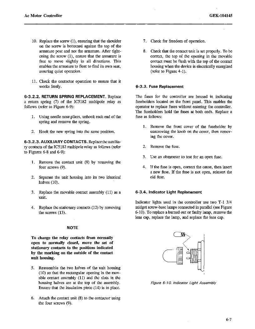
Indicator lights used in the controller use two T-l 3/4 midget screw-base lamps connected in parallel (see Figure 6-10). To replace a burned out or faulty lamp, remove the lens cap, replace the lamp, and replace the lens cap.
Figure 6-10. Indicator Light Assembly
6-7

GEK-104145 AC Motor Controller
6-3.5. Pushbutton Replacement
There is no recommended maintenance for the push- buttons used in the controller. A pushbutton should be replaced as a unit as follows:
1. Remove the pushbutton assembly from the controller door by removing the two screws that hold the pushbutton assembly and nameplate in place. Remove the nameplate and pull the switch from the controller door.
2. Tag all wires so that they can be reconnected correctly, then disconnect the wires from the pushbutton assembly.
3. Connect the wires as tagged to the new pushbutton assembly.
6-3.6. Relay, Switch, and Transformer Replacement
There is no recommended maintenance for the timing relay (Agastat), control switches, control power trans- former, or current transformers used in the controller. These devices should be replaced using the following general procedure (see transformer Tables 6-l and 6-2):
1. Dismount the device by removing the screws that hold it in place.
2. Tag all wires so that they can be reconnected correctly, then disconnect the wires from the device.
3. Connect the wires as tagged to the new device.
4. Mount the new device and secure it with the mounting screws.
4. Insert the new pushbutton into the controller door and place the nameplate into position. Mount the pushbutton and nameplate using the two screws.
Table 6- 1. Autotransformer Data
Part Number Percentage of Tap
Number of Turns Condition Between Taps in Parallel
Transformer 3323806 0 - 50 30 2
50 - 65 14 and 5 2 and 4
65- 80 5 and 3 4 and 6
SO- 100 6 and 6 6 and 6
Table 6-2. Current Transformer Data
Part Number Current Wire Size Ratio
Transformer 750X1 2G7 300 A 3/o 60/l
5A 15 60/l
6-X

AC Motor Controller GEK-104145
CHAPTER 7
PARTS LIST
7-1. INTRODUCTION
This chapter identifies the major components of the GE IC5130B38 ac motor controller. The list enables the user to identify and order replaceable parts. Table 7-l lists the controller replacement parts. Figure 7-l shows the controller with the parts identified.
7-2. USING THE PARTS LIST
In Table 7-1, the Figure and Item Number column references the drawing and the item number in that drawing for each part. The FSCM column identifies the Federal Supply Code identification number for the manufacturer of each part. The other columns describe the part, list the number of parts per controller, and identify the manufacturer’s part number for ordering that part. To use the table for replacing a part:
1. Identify the item to be replaced by the manu- facturer’s part number on its nameplate (unless the nameplate has been damaged or lost).
3.
4.
5.
6.
2. If the item nameplate is intact., identify the part
Table 7-1. Parts List
by matching the manufacturer’s part number in the table with the number listed on the item nameplate. Go to step 5. If there is no readable nameplate, use Table 7-1 to find the figure that identifies the part, and refer to that figure.
In the figure, locate the item to be replaced and note the identification number for that item in the figure. Refer back to Table 7-l.
Under the parts listing for the controller, match the item number in the figure with that listed in the table. Go to the column that lists the manu- facturer’s part number for that item.
Find the FSCM number for the manufacturer. Refer to Table 7-2, which identifies the manu- facturer by the FSCM number and gives the manufacturer’s address.
Contact the manufacturer and order the number of parts needed, using the manufacturer’s part number and the description of the part.
Figure and Item Number
Name of Part Quantity Per Set Manufacturer’s Part Number FSCM
7-I,13
6-6, 23
6-6, 14
6-6, 11
6-6, 15
6-6, 7
6-7, 18
6-7, 19
7-I,18
6-4, ---
Contactor (Y)
Coil
Movable contact
Stationary contact
Contact spring
Return spring
Internal movable contact
Internal stationary contact
Contactor IS)
Coil
1 IC5 18 1 Cl 04AGXAXX 02989
1 174A766766 02989
3 174A531’5Gl 02989
6 174A5316Gl 02989
3 174A7635Pl 02989
1 174A7633Pl 02989
1 129B688261 02989
4 174A7137Pl 02989
1 IC5181 Cl 05AGXABA 02989
1 193A9636G6 02989
7-l

GEK-104145 AC Motor Controller
Table 7-1. Parts List - Continued
Figure and Item Number Name of Part Quantity Per Set Manufacturer’s
Part Number FSCM
6-4, 14
6-4, 11
6-4, 15
6-4, 7
6-7, 18
6-7, 19
7-1, 1
6-4, ---
6-4, 14
6-4, 11
6-4, 15
6-4, 7
6-7, 18
6-7, 19
7-1, 17, 6, 4, 16, 7
6-9, 15
6-9, 11
6-9, 12
6-9, 7
7-1, 15
6-2, ---
2-1, 1
6-l 0, ---
6-1 0, ---
6-1 0, ---
2-1, 8 & 6
2-1, 9 & 5
2-1, 7
7-I,14
7-1, ,I 1
7-1, 2 & 3
7-I,12
Movable contact
Stationary contact
Contact spring
Return spring
Internal movable contact
Internal stationary contact
Contactor (R)
Coil
Movable contact
Stationary contact
Contact spring
Return spring
Internal movable contact
Internal stationary contact
Relay (RI - R3, SR, RM)
Coil
Movable contact
Stationary contact
Return spring
Overload relay (OL)
Overload heater
Fuse (I FU, 2FU)
Indicating light (2 - 4lL, 9lL, IOIL)
Indicating light (1 IL)
Lamp
Control switch (1 CS, 2CS)
Pushbutton (I PB, 2PB)
Pushbutton (RESET)
Control power transformer (CPT)
Autotransformer (AT)
Control transformer (1 CT, 2CT)
Timing relay (TR)
6
12
6
2
6
24
1
1
6
12
6
2
6
24
5
5 (1 per relay)
20 (4 per relay)
50 (IO per relay)
5 (I per relay)
1
2
2
5
1
12
2
2
1
1
1
2
1
188A4581 Gl
188A4583Gl
193A9473Pl
193A9474Pl
129B6882Gl
174A7137Pl
IC5181 Cl 06AGXABA
193A.963666
188A4581 Gl
188A4583Gl
193A9473Pl
193A9474Pl
129B6882Gl
174A7137Pl
IC5182C120A3AAAA
174A7624G3
129B6882Gl
174A7137Pl
181A5988Pl
IC5882D121 B
See Table 7-3
F6OC5OOVl OAS
288A896AAPl
288A896AAP2
288A896BFP3
288A886XTPl
5729215Gl
188A1770Gl
573A499FZP7
3323806
750X1 2G7
231 B244AFP23
02989
02989
02989
02989
02989
02989
02989
02989
02989
02989
02989
02989
02989
02989
02989
02989
02989
02989
02989
02989
02989
02989
02989
02989
02989
82121
02989
02989
83325
02989
02989
98403
7-2

AC Motor Controller GEK-104145
1 Contactor (RI 2 Control transformer (I CT)
/43
7 Relay WWI 13 Contactor (Y) 8 Terminal board (2TB) 9 Terminal board (3TB) 10 Terminal board (4TB) 11 Autotransformer (AT) 12 Timing relay (TR)
14 Control power transformer (CPT)
15 Otierload relay (OL) 16 Relay (SRI 17 Relay (RI 1 18 Contactor (S)
3 Control transformer (2CT) 4 Relay (R3) 5 Terminal board (ITB) 6 Relay (R2)
Figure 7- 1. Controller Parts Location
7-3

GEK-104145 AC Motor Controller
Table 7-2. List of Parts Manufacturers
FSCM Manufacturer
02989
98403
82121
83325
GE Drive Systems 1501 Roanoke Boulevard Salem, VA 24153
Amerace Corporation Control Products Division 1000 Hickory Street Grafton, WI 53024
Electra Switch Corporation 180 King Avenue Weymouth, MA 02188
SNC Manufacturing Company, Incorporated 101 Waukau Road Oshkosh, WI 54901
Table 7-3. Overload Heater Part Numbers
Heater Part Continuous Motor Load - Amps
Number Minimum Maximum
81 D322 127 136
81 D323 139 153
81 D324 154 168
81 D325 169 185
81 D326 186 205
81 D327 206 225
81 D328 226 246
81 D329 247 261
81 D330 262 289
7-4

AC Motor Controller GEK-104145
CHAPTER 8
INSTALLATION
8-l. INTRODUCTION
This chapter contains the information necessary to install the equipment. Before performing any installation work, consult the drawings in this manual.
8-2. RECEIVING AND HANDLING
General Electric carefully inspects and packs all equip- ment before shipping it from the factory. Upon receipt of this equipment, immediately inspect it for missing or damaged items. A packing list, included in each case of the equipment, itemizes the contents of each package of the shipment. When unpacking, check the contacts of each case against the packing list. Carefully inspect the packing material to avoid losing small parts.
If damage is evident or if there is visual indication of rough handling, immediately file a damage claim with the carrier. Then notify both the transportation company and General Electric Company.
The equipment is shipped with a 3-inch by 30-&h lifting angle (see Figure 8-l). The equipment is shipped in an upright position, which should be maintained during handling. Never attempt to jack, lift, or move the equip- ment at points other than the lifting angle or floor sills. The lifting angle should be removed only upon installa- tion.
El
CAUTION
Before moving equipment, ensure that the doors are closed and their thumb screws are fastened.
8-2.1. Removing the Lifting Angle
The lifting angle (see Figure S-1) is bolted through l-inch thick washers into weld nuts on the inside top of the equipment. Lifting holes are 5/8 inches in diameter.
8-3. UNPACKING
It is good practice to not completely unpack the equipment until it has been placed as near as possible to its intended permanent location. Use standard unpacking tools, including a nail puller. Carefully remove equipment from its container to avoid damaging or marring the part.
Small parts (such as bolts and screws) are packed in special containers to keep them together, but they may become separated. For this reason, carefully inspect packing material for loose parts before discarding it. Wipe off any particles of packing material or foreign substances that may be lodged in or between the parts.
8-4. STORAGE
If the equipment is not installed immediately upon receipt, use the following storage procedures to protect it from breakage, corrosion, damage, and deterioration:
1. Unpack and label the equipment.
2. The packing coverings do not protect the equipment for outdoor storage. Place the equip- ment under adequate cover, with the following precaution:
a. Keep the equipment clean and dry, and protect it from extreme temperature varia- tions, high humidity, dust, and rodents.
b. Use only breathable (canvas type) covering material - do not use plastic.
c. Absolute storage temperature limits are -40 “C (-40 “F) to 70 “C (158 “F).
d. Equipment may be stored in environments of 595% relative humidity with provisions to prevent condensation.
3. To prevent moisture condensation on the equip- ment, as caused by variations in the storage temperature, keep the equipment’s internal
8-l

GEK-104145 AC Motor Controller
15.50 x 3.50 CUTOUT WITH UNDRILLED COVER PLATE
\
I NO-E ALL DIMENSIONS ARE IN INCHES
-1.25 r-‘5*25 -7
1.25 - ir i- + TOP
0 0 -------- , ’
Tg-’ I I I !S I+ 1.25
I
) 1 (OOosdsDFkN)
-20.20 -
FRONT - 28.00 -
13.55 13.55
I I I .@3 8
15.50 x 3.50 p f CO;-9-; c
+ Q
8.50 ,Q3 G3 i @
-L 2.35
-r 7.75
t 7.75
t
I-- 33.50 -
MOUNTING HOLES FOR .75 DIA. HARDWARE (QUANTITY 8)
FLOOR PLAN
Figure a- 1. Controller Outline Drawing and Mounting Details
8-2

AC Motor Controller GEK-104145
temperature 5-10 “C higher than the outside ambient temperature. This can be done by adding space heaters or by using panel space heaters, when supplied. (Heaters require an external ac power supply.)
I CAUTION I
Remove all cartons and other miscellaneous material packed inside units before energizing any heaters.
8-5. INSTALLATION
8-5.1. Preparation
Before starting any installation, consult and study all furnished drawings. These drawings should include arrangement drawings, connection diagrams, elementary diagrams, and a summary of the equipment.
8-5.2. Mounting
Each controller is to be deck mounted on a flat surface. Take care not to twist or warp the enclosure. The outline drawing for the enclosure (see Figure 8-l) specifies the number, size, and location of bolts for mounting.
The mounting dimensions allow a normal factory toler- ance of +_ l/16 inch. Therefore, alignment problems may occur if mounting provisions are based upon the drawing dimensions. Also note that the mounting bolt clearance holes located in the enclosures are only l/32 inch oversize per MIL-S-901, “Shockproof Equipment, Class HI (High Impact), Shipboard Applications, Tests for.”
8-5.3. Incoming Cabling and Wiring
) WARNING 1
Before handling and connecting any power cables to the equipment, ensure that all power supplies are turned off. Then check voltage levels on the wiring to ensure that the wiring is not carrying hazardous voltages.
The required power input to the controller is 440 V ac, 3- phase, 60 Hz. Table 8-1 shows the external wiring connections to the controller.
8-6. INSPECTION AND PREENERGIZING PROCE- DURES
After completing the installation, wiring, and normal circuit checks, the technician should complete the follow- ing actions before energizing the equipment:
1, Verify that each controller is installed according to the specifications described in paragraph 8-5.
2. Megger all terminals for grounds. Isolate from the circuit any control device or instrument that is sensitive to megger voltage.
Table 8-1. External Wiring Connections
Type of Input
Motor
Connections ’
Tl (ITB-1) T2 (ITB-2) T3 (ITB-3)
Power Ll L2 L3
Terminal Board ITB-1 (wire Tl) 1 TB-2 (wire T2) 1 TB-3 (wire T3) 2TB-7 (wire 3) 2TB-2 (wire 4) 2TB-3 (wire 5) 2TB-4 (wire 6) 2TB-5 (wire 7) 2TB-6 (wire 8) 2TB-7 (wire 14) 2TB-8 (wire 15) 2TB-9 (wire 16) 2TB-IO (wire 17) 3TB-1 (wire 19) 3TB-2 (wire 20) 3TB-3 (wire 21) 3TB-4 (wire 23) 3TB-5 (wire 24) 3TB-6 (wire 32) 3TB-7 (wire 33) 3?B-8 (wire 34) 3TB-9 (wire 35) 3TB-IO (wire 39) 4TB-1 (wire 40)
8-3

GEK-104145 AC Motor Controller
3. Operate each magnetic device by hand to ensure that all moving parts operate freely. Check all electrical interlocks for proper operation.
4. If a current transformer circuit is not complete, it is shipped with a shunt across the secondary. During installation, complete the connections to the transformer secondary, then remove the shunt.
5. Ensure that the horsepower rating and voltage of the ac motor do not exceed those stamped on the controller nameplate.
6. Check each overload heater against the full load current listed on support drawings.
7. Clean the controller interior with a dry rag or compressed air.
8-7. TURN ON AND PRELIMINARY TESTS
1. Turn on the controller according to the instruc- tions in Table 2-2.
2. Verify the incoming and outgoing power with the schematic diagram in Figure 5-1.
8-8. INSTALLATION VERIFICATION TEST
1. After each controller unit has passed the steps in sections 8-6 and 8-7, verify that all indicating lights are properly lit and that all controls func- tion according to their descriptions in TabIe 2-l.
2. If a malfunction is detected, troubleshoot accord- ing to the instructions in Chapters 5 and 6.
8. Close the controller door and turn all disconnects to OFF before energizing the controller.
8-4