Embed Size (px)
Citation preview
Technical Manual for LG Rotary Compressor
Version. 1
LG Electronics Inc. Air Conditioning Compressor Division
Contents
Ⅰ. Looking into Compressor1. How the Rotary Works2. Features of Rotary Compressor
Ⅰ - 1
Ⅰ - 2
Ⅰ - 3
Ⅱ. System Design1. Basic Specification of Rotary Compressor2. Selection of Compressor3. Compressor Cooling4. Heat Exchanger Design5. Capillary Tube6. Refrigerant Charge7. Selection of Accumulator8. Refrigerant Oil9. Moisture Control
10. Piping Design11. Sound Reduction
Ⅱ - 1
Ⅱ - 2
Ⅱ - 3
Ⅱ - 3
Ⅱ - 3
Ⅱ - 4
Ⅱ - 6
Ⅱ - 8
Ⅱ - 8
Ⅱ - 8
Ⅱ - 9
Ⅱ - 11
Ⅲ. Application1. General limitations2. Compressor Installation3. Interconnecting Tube4. Electrical Components and Wiring5. General Cautions
Ⅲ - 1
Ⅲ - 2
Ⅲ - 3Ⅲ - 3
Ⅲ - 4
Ⅲ - 5
Ⅳ. Trouble Shooting Ⅳ - 1
1. Trouble Shooting Ⅳ - 2
0 - 1
Ⅰ- 1
Ⅰ. Looking into Compressor
1. How the Rotary Works2. Features of Rotary Compressor
1. How the rotary works
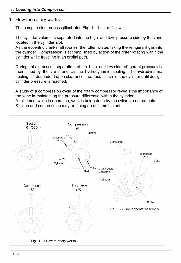
The compression process (illustrated Fig. Ⅰ- 1) is as follow ;
The cylinder volume is separated into the high and low pressure side by the vanelocated in the cylinder slot.As the eccentric crankshaft rotates, the roller rotates taking the refrigerant gas intothe cylinder. Compression is accomplished by action of the roller rotating within thecylinder while traveling in an orbital path.
During this process , separation of the high and low side refrigerant pressure is maintained by the vane and by the hydrodynamic sealing. The hydrodynamic sealing is dependent upon clearance , surface finish of the cylinder until design cylinder pressure is reached.
A study of a compression cycle of the rotary compressor reveals the importance ofthe vane in maintaining the pressure differential within the cylinder.At all times, while in operation, work is being done by the cylinder components.Suction and compression may be going on at same instant.
Compression180
Discharge270
Suction0 (360 )。 。
Fig. Ⅰ- 2 Components Assembly.
Fig. Ⅰ- 1 How to rotary works.
Crank shaft
DischargePort
Vane
Cylinder
Roller
Crank shaftEccentric
。 。
Compression90
DischargeValve
Vane
Cylinder
Suction
RollerShaft
。
Ⅰ. Looking into Compressor
Ⅰ- 2
2 Features of Rotary Compressor
2.5 Less over compression
As the roller makes it’s path around the cylinder, the vane confines the gas at onepoint, and the roller at another point.This direct suction minimize intake losses since the suction takes places continuously and the suction port is isolated from the discharge port by the vane and the roller.Furthermore, rotary compressors are less affected by liquid return than recipro-cating compressors, since they have no suction valve.
2.1 No suction valve ( Direct suction )
The suction gas enters directly into the cylinder and is compressed before beingdischarged into the shell, where if flows over and around the motor windings before moving into the condenser.In reciprocating compressors, on the other hand, the suction gas enters into the shell, where it is further vaporized , contacting the hot motor windings and then taken into the cylinder.Therefore, superheat of suction gas in the compressor is higher than that of rotarycompressors. Higher superheat of suction gas provides a little bit superheat causes higher discharge gas temperature.
2.2 Less heat transfer to the suction gas
Re-expansion losses are limited by the small top clearance and their inherent design.Thus, almost 100% of the available displacement is utilized.
2.3 Less re-expansion loss
The cool return gas enters directly into the cylinder. The vapor is compressed bythe rotary pump and receives the heat of compression. The warm gas then passes
over the motor to receive the heat from the windings.Even though, the vapor is warmer than it was prior to compression, it is also muchmore dense. This denser gas is capable of receiving greater amounts of heat pergiven volume than thin suction gas to cool a motor in reciprocating compressor.
2.4 Better motor cooling
The liquid refrigerant also undergoes into the cylinder of the rotary compressor withthe suction gas, but the radius on the nose of vane facilitates this action and the vane is lifted momentarily allowing a part of the liquid to be unloaded into the low side of the cylinder.In this way, all of the liquid refrigerant can be gradually disposed of in successivecompression cycles without damage.Such liquid causes excess foaming and the maximum pressure in the cylinder sometimes will reach approximately 150㎏/㎠G.
Ⅰ. Looking into Compressor
Ⅰ- 3

In the rotary compressor, the shell and motor stator are in direct contact.The shell, as a matter of fact, is shrunk fit around the stator and the mechanical portion of the pump is welded to the shell. And the suction gas enters directly into cylinder. These features can make some parts, such as In general, the weightof the rotary compressors is approx. half or three quarters of current reciprocating compressors of comparable capacity and one quarter smaller in size.
2.6 Less weight and size
2.7 Characteristic
*Motor rotation is directly transferred through crankshaft to compression work without conver-ting it to reciprocation process like conventional reciprocating compressor. This mechanism provides high efficiency work.
*Torque variation in single process is distributed over single rotation (360 ) and results in rather smaller variation in torque, and it leads to lower motor input.(see Fig.Ⅰ- 3)
Torq
ue
Recipro.
Rotary
0。 90。 。 。180 270。 360Crankshaft angle
。
*Pull-down load is smaller in rotary compressor and the motor can be smaller as much.This also contributes to higher E.E.R.(see Fig.Ⅰ- 4)
*Rotary compressor sound level appears over the range of rather higher frequency band (3,000 - 6,000 Hz), which is easier to design in sound insulation.
*Rotary compressor requires less number of parts and this contributes to less failure rate as much.
*Compressor size is compact and this leaves room for flexible design of system componentsfor higher E.E.R.
Fig. Ⅰ- 3
Recipro.
Rotary
Cur
rent
Time
Fig. Ⅰ- 4
Recipro.
Rotary
E.E.
R
Fig. Ⅰ- 5
Evaporating Temp.
Ⅰ. Looking into Compressor
Ⅰ- 4
Ⅱ. System Design
1. Basic Specification of Rotary Compressor2. Selection of Compressor3. Compressor Cooling4. Heat Exchanger Design5. Capillary Tube6. Selection of Accumulator7. Refrigerant Charge8. Refrigerant Oil9. Moisture Control
10. Piping Design11. Sound Reduction
Ⅱ - 1

General
Under normal operating conditions, equipment designers can anticipate dischargegas with thermodynamic characteristics which are almost identical with thoseobtainable with reciprocating compressors : in extreme conditions , rotary compre-ssor performance is superior to that of conventional design.
The rotary compressors can, therefore, be incorporated in existing systems andequipment without extensive engineering changes.The design procedure of equipment does not involve nay special methodology except for an discharge gas cooling.If a compressor is not operated properly, it will not exhibit its best performance and also shorten its service life.In extreme cases, it may even malfunction and break down.
These operating instructions have been prepared so that the rotary compressors can be used properly and efficiently without malfunction and breakdown and they list the operation standards and handling precautions.It is recommended that you acquire a full understanding of the special properties of the compressors so that you can operate them properly.
1. Basic specification of rotary compressor
The rotary compressor is fundamentally different from the conventional recipro-cating compressor in the following points.Therefore, careful design conditions are required when designing system.
Table Ⅱ- 1. Basic specifications of rotary compressors
Basic items
Compressor shell pressure
Shell temp.
Compressor cooling
Intake method of suction gas
Inside supporting structureof compressor
DifferenceReciprocating Rotary
Low side Hi sideLow High
Natural air coolingForced air cooling
Natural air coolingForced air cooling
Liquid injection coolingIndirect intake to
cylinderDirect intake into
cylinderInner supporting or
suspension Shrink fitting
Ⅱ. System Design
Ⅱ - 2

4. Heat exchanger design
The cooling method in LG rotary compressor is baldy type.Baldy type means no de-superheater and no liquid injection cooling. This type is available for small and medium power range because emission of heat from shell surface will do. Different from either de-superheater type or liquid injection type, special constructionis not employed for cooling discharge gas, and this type is effective for unit with light load and with good heat ejection from compressor. The compressed gas of this type is discharged directly to the compressor shell and the motor is surrounded by the high temperature discharge gas.Therefore the motor winding temperature is apt to go up.LG recommends a maximum discharge gas temperature of 240℉ (120℃) at maximum load / minimum voltage conditions.
3 Compressor cooling
Heat exchanger is the major component which affects performance of room air-conditioners. Heat exchange rate is determined by its size, air volume, fin pitch and others.
4.1 CondenserThe condenser and its air moving device directly affect the compressor’s powerconsumption.It is therefore, advisable when operating efficiency is of primary consideration that condensing heat transfer be enhanced, consequently, the compressor’s power consumption. (see Fig.Ⅱ- 1)
Ⅱ. System Design
2. Selection of compressor
The experienced system engineer selects components which when assembledinto the air conditioner will give the desired unit performance , especially with respect to capacity and efficiency.LG Electronics furnishes specification sheets for each of its various models.The data is provided in a manner to permit the engineer to make a direct compari-son with the reciprocating compressor of the same rating or any other rotary compressor that is now in use.
4.2 EvaporatorThe evaporator, in conjunction with the volume of indoor air passing through it, is the other major component affecting the air conditioner’s capacity.Whenever any of the increase heat transfer, the evaporator temperature increase and an increase in unit capacity will result.(see Fig.Ⅱ- 2)To summarize, in order to obtain excellent E.E.R.Increase evaporating temperature and reduce condensing temperature.
Ⅱ - 3

Rotary
Recipro.
Approx. 10℃
Coo
ling
Cap
acity
Inpu
t
Recipro.
Rotary
Approx. 5℃
Condensing Temp. 54.4℃Evaporating Temp.
Fig. Ⅱ- 2
Inpu
t Recipro.
Rotary
Approx. 58~60℃
Fig. Ⅱ- 1
Evaporating Temp. 7.2℃Condensing Temp.
5.1 GeneralIn the refrigerating equipment using the capillary tubes , the torque for starting compressors can be minimized because the pressure between high and low side is easily balanced through the capillary tube during the compressor stoppage.Although the capillary tube flows the gas phase refrigerant better than the liquid phase refrigerant, we can not say that it is widely effective for various operating condition. But for the usual application, the engineers can have good result with the capillary tube in refrigerating operation. And the engineers have the advantage of cost saving, simplicity, stable quality comparing the expansion valve.
Size of capillary tube is determined by condensing temperature , evaporatingtemperature, subcool, etc.Even if there is some variation in ambient temperature subcool should be securedto some extent at least.If not , it may cause flash gas and results in harmful effects,i.e, shortage of coolingcapacity, blockage of capillary tube or abnormal sound.
Ⅱ. System Design
5. Capillary tube
5.2 Selection by calculation
Find the mass flow rate (kg/hr) of refrigerant.(Refer to the each performance curve attached)
Find the coefficient of mass flow (Refer to the Fig. Ⅱ- 3)
●
●
The mass flow rate (kg/hr)The mass flow rate refer to Fig. Ⅱ- 4 (kg/hr)
The coefficient of mass flow (Φ) =
Ⅱ - 4

Find the inside diameter and length of capillary(Refer to the Fig. Ⅱ- 3)
70 (kg/hr)58 (kg/hr)
Sol) Refer to the performance curve for QK182CN.
The mass flow = 70 kg/hrThe coefficient of mass flow (Φ) = = 1.2
Ex) Under the operating conditions as below,
The compressor model : QK182CNRefrigerant : R-22Condensing Temp. : 54.4℃Sub-cooled to 46.1℃
Refer to the diagram. Ⅱ- 3,If I.D is Φ1.6mm (0.063”), length is 1.4m (55.12”)
Φ1.8mm (0.071”), length is 2.5m (98.43”)Φ2.0mm (0.079”), length is 5.0m (196.85”)
●
●
Ⅱ - 5
Fig. Ⅱ- 3 Coefficient of flow rate (Critical pressure of capillary tube inlet)
Fig. Ⅱ- 4 Flow rate of capillary inlet(Critical pressure of tube inlet)
140.0
120.0
100.0
1.0
2.0
3.0
4.0
5.06.07.0
10.0
20.0
30.0
50.0
40.0
60.070.0
Flow
Rat
e (k
g/h)
Subcooled 30℃
Capillary TubeI.D. = 1.63㎜Length = 2.03m
20℃
15℃
10℃
8℃6℃4℃
2℃
Degree o
f dryn
ess 0%
2.5%
5%10
%20
%40
%80
%
Ⅱ. System Design
Coe
ffici
ent o
f Flo
w R
ate
(Φ)
4.00
3.00
2.00
1.50
1.00
0.70
0.50
0.40
0.30
0.20
0.15
5.0
4.5
4.0
3.5
3.0
2.82.62.42.2
2.0
1.8
1.6
1.4
1.2
1.0
0.9
0.8
0.7
0.6
I.D of Capillary Tube (㎜)
30.00
20.00
15.00
10.00
7.00
5.00
0.10 1 1.5 2 3 4 5 6 7 10 15 20 25 30 35(㎏/㎠abs)
0.07 Saturated Temp.for R-12 70 (℃)-30 -25 -20 -10 -5 0 10 20 30 40 50 600.05
0.3 0.5 1.0 1.5 2.0 3.0 5.0 7.0 10.0 12.0 Saturated Temp.for R-22 (℃)-30 -25 -20 -10 -5 0 10 20 30 40 50 60 70
Length of Capillary Tube (m)

5.3 Optimum selectionIt is still in question that the pre-determined capillary tube may well operate with the charging amount of refrigerant. Because it is difficult to find out the optimumselection of the capillary tube and the charging amount of refrigerant, is necessaryto repeat the test.For simple method to test , prepare a small bomb which refrigerant is filled in and connect it to the refrigerant cycle with flexible tube.Then put the bomb on the scale and open or close the valve between the bomb and the cycle to increase or decrease the refrigerant. Checking the cooling capacity and power consumption.The finally selected capillary tube will be cut off the cycle and after air-mass-flow characteristic test be used for purpose of the quality control of mass production.
The charged volume of the refrigerant should be determined depending on respective system design.However, when the refrigerant is over charged , it returns to the compressor excessively at start-up , which may prevent the compressor from restarting properly, causing inferior lubrication and trouble due to liquid compression.Minimum refrigerant charge is usually required but it is necessary to secure proper subcool, cooling capacity, and discharge temperature.As a general rule, refrigerant charge is discussed by the following formula.
Oil weight≥ 0.25
Refrigerant weight + Oil weight
When the weight ratio between the oil and the refrigerant reaches less than 0.4,the compressor may have a trouble due to the supply and the diluted oil.
Ⅱ. System Design
6. Refrigerant charge
7. Selection of accumulator 7.1 Selection of volume
Effective Volume of accumulator
Specific Gravityof Refrigerant ×
Charged Weight of Refrigerant ≥ K
※ Specific gravity of refrigerant (R22) = 1.25 (at 20℃)
System
Window Type (cooling only)3/4 HP ↓3/4 HP ↑
K
• Window Type for Heat Pump• Split Type (cooling only)• Split Type for Heat Pump• Multi-zone Heat System
0.10.3
0.4
0.6
Table. Ⅱ- 2. Select of Value “A”
Ⅱ - 6

Specification(㎜)
Effective Volume Application
Φ31.8 × L 168
Φ50.8 × L 200
Φ65.0 × L 263
Φ75.0 × L 229
Φ75.0 × L 259
140㏄
450㏄
490㏄
560㏄
Φ75.0 × L 292 670㏄
Φ65.0 × L 221 380㏄
QA Series
QB & QK Series
QP Series
QP Series
QB & QK & QJ Series
QB & QK & QJ Series
QB & QK & QJ Series
Φ50.8 × L 220 176㏄ QB & QK Series
41㏄
Ⅱ. System Design
If) 1. Charged weight of refrigerant : 1000g (for Split type Heat pump)Effective Volume of Accumulator : 480㏄ Min.
2. Charged weight of refrigerant : 800g (for Split type Heat pump)Effective Volume of Accumulator : 384㏄ Min.
7.2 Effective Volume of Accumulator for LG Rotary Compressor
Table. Ⅱ-3. Effective Volume of Accumulators
7.3 Accumulator Volume for Refrigerant Charging Amount
Window Type
3/4HP ↓ 3/4HP ↑
• Window Type for H/Pump
• Split Type
• Split Type for H/Pump
• Multi-zone Heat
72 ㏄ 96 ㏄ 144 ㏄96 ㏄ 128 ㏄ 192 ㏄
120 ㏄ 160 ㏄ 240 ㏄144 ㏄ 192 ㏄ 288 ㏄168 ㏄ 224 ㏄ 336 ㏄
20 ㏄24 ㏄32 ㏄40 ㏄48 ㏄56 ㏄ 192 ㏄ 256 ㏄ 384 ㏄
216 ㏄ 288 ㏄ 423 ㏄240 ㏄ 320 ㏄ 480 ㏄264 ㏄ 352 ㏄ 528 ㏄288 ㏄ 384 ㏄ 576 ㏄312 ㏄ 416 ㏄ 624 ㏄336 ㏄360 ㏄384 ㏄408 ㏄432 ㏄456 ㏄
Refrigerant Charge (g)
~ 300300 ~ 400400 ~ 500500 ~ 600600 ~ 700700 ~ 800800 ~ 900900 ~ 1000
1000 ~ 11001100 ~ 12001200 ~ 13001300 ~ 14001400 ~ 15001500 ~ 16001600 ~ 17001700 ~ 18001800 ~ 19001900 ~ 2000 480 ㏄
448 ㏄480 ㏄512 ㏄544 ㏄576 ㏄608 ㏄640 ㏄
Table. Ⅱ- 4. Refrigerant Charging Amount
Ⅱ - 7
8. Refrigerant oilIn order to maintain a high degree of reliability, a refrigeration oil which is speciallydeveloped for the rotary compressor is used.Therefore, no other type of oil must be used. LG rotary compressor is charged withSUNISO 4GS grade.
Ⅱ. System Design
9. Moisture control & Dehydration9.1 Effects of moistureIf moisture resides in the system, it may cause the undesirable results as below.
1) The freezing blockage of capillary tube, expansion valve.2) Metal corrosion and sludge.3) Valve fracture.4) Copper plating.5) Deterioration of insulation material.
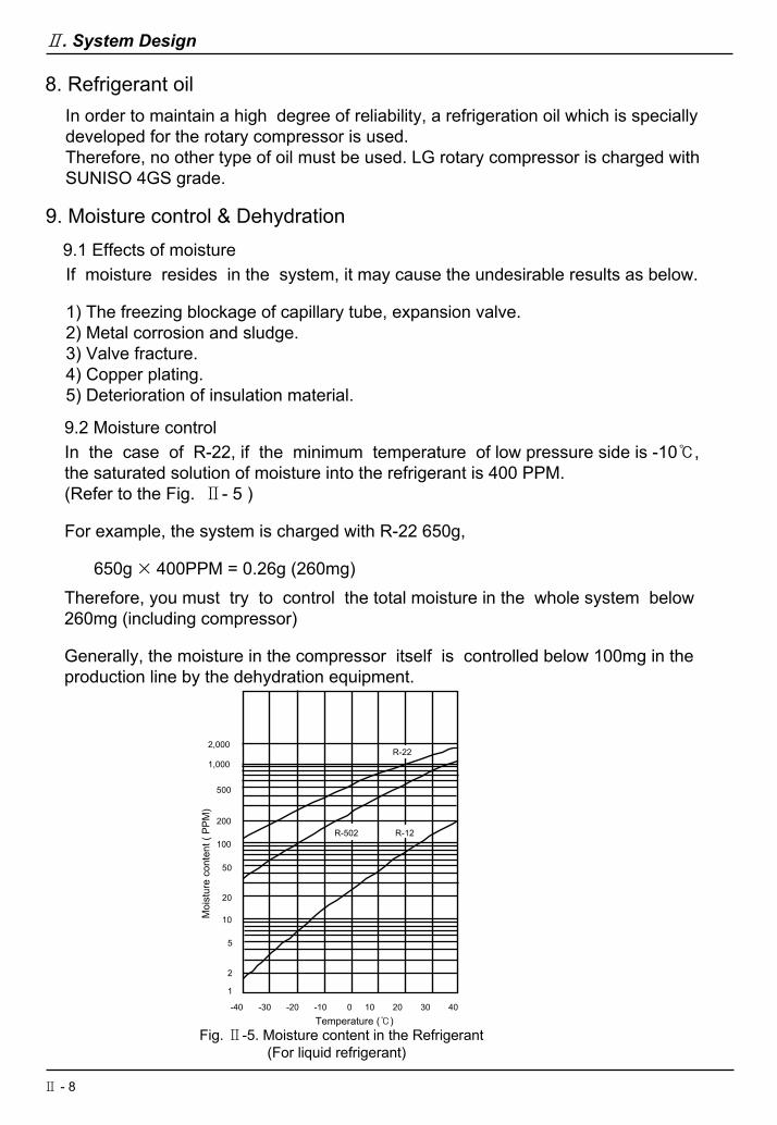
9.2 Moisture controlIn the case of R-22, if the minimum temperature of low pressure side is -10℃, the saturated solution of moisture into the refrigerant is 400 PPM. (Refer to the Fig. Ⅱ- 5 )
For example, the system is charged with R-22 650g,
650g × 400PPM = 0.26g (260mg)Therefore, you must try to control the total moisture in the whole system below 260mg (including compressor)
Generally, the moisture in the compressor itself is controlled below 100mg in the production line by the dehydration equipment.
2,000
1,000
500
-40 -30 -20 -10 0 10 20 30 40
1
2
5
10
20
50
200
100R-502 R-12
R-22
Fig. Ⅱ-5. Moisture content in the Refrigerant(For liquid refrigerant)
Temperature (℃)
Moi
stur
e co
nten
t ( P
PM)
Ⅱ - 8

Discharge Line
Suction Line
DampingStrapper
Discharge Line
Suction Line
DampingStrapper
Example 2Example 1
Fig. Ⅱ- 6. Recommended Piping Design
Ⅱ. System Design
10. Piping designPiping design piping properly so that it will not cause breakage of piping in transportation, at compressor start-up, stop or dying compressor operation.The following points should be borne in mind when designing and determiningthe piping.
10.1 Piping form
Vibration in the circumferential direction of the rotary compressor is larger thanthat of conventional reciprocating compressor.Therefore, a loop should be provided for the refrigerant piping to avoid stressconcentration at the inlet/outlet of the compressor.The illustrations (see Fig.Ⅱ- 6) are example of recommended piping design.
10.2 Distance of piping
The pipe which connects a compressor to the refrigeration cycle, especially lead wire, shall not being contacted together with having proper distance.Normal distance for piping is as following. ( See Table.Ⅱ- 5)
Distance of piping
Min. 12.7 mm
Min. 9.5 mm
Moving parts(Compressor, fan...)
Non-Moving parts
Table. Ⅱ- 5. Distance of Piping
Ⅱ - 9
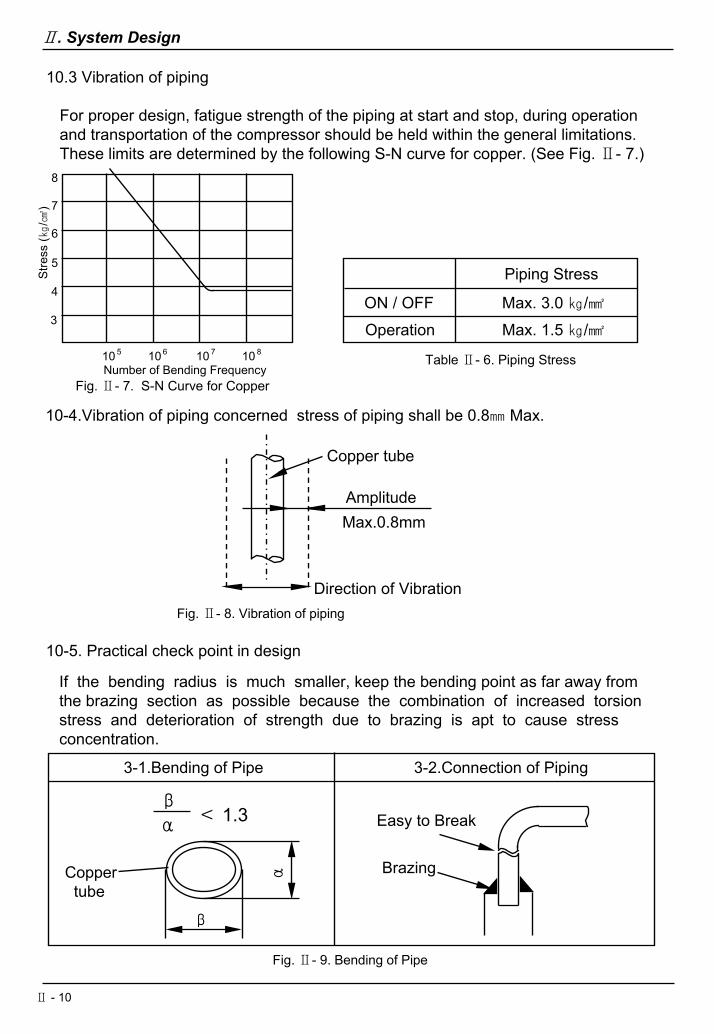
Fig. Ⅱ- 7. S-N Curve for CopperNumber of Bending Frequency
8
7
6
5
4
3
10 6 10 7 10 810 5
Stre
ss (㎏
/㎠)
10.3 Vibration of piping
For proper design, fatigue strength of the piping at start and stop, during operationand transportation of the compressor should be held within the general limitations. These limits are determined by the following S-N curve for copper. (See Fig. Ⅱ- 7.)
Ⅱ. System Design
Piping Stress
Max. 3.0 ㎏/㎟ON / OFFOperation Max. 1.5 ㎏/㎟
Table Ⅱ- 6. Piping Stress
10-4.Vibration of piping concerned stress of piping shall be 0.8㎜ Max.
Copper tube
AmplitudeMax.0.8mm
Direction of VibrationFig. Ⅱ- 8. Vibration of piping
10-5. Practical check point in design
If the bending radius is much smaller, keep the bending point as far away from the brazing section as possible because the combination of increased torsion stress and deterioration of strength due to brazing is apt to cause stress concentration.
3-1.Bending of Pipe
α
β
Coppertube
α
β
< 1.3
3-2.Connection of Piping
Brazing
Easy to Break
Fig. Ⅱ- 9. Bending of Pipe
Ⅱ - 10

Ⅱ. System Design
11. Sound reduction11.1. Reduction of compressor noise and vibration
11.1.1. As most of noise caused by the rotary compressor are those of highfrequency 2,000 ~ 6,000 Hz, they can be insulated by effectively noise absorbing partition.
11.1.2. When the air conditioning unit causes noise of 200 ~ 500 Hz due to the vibration of the rotary compressor, the following noise insulation required.① Check the piping resonance.② Check the compressor mounting condition.
11 2. Fan noise reduction11.2.1 Air flow resistance shall be reduced in accordance with following
improvements.① Size up front surface of heat exchanger.(Indoor)② Reduce pressure loss of air filter. (Indoor)③ Improve inlet grille, flapper and air outlet.(Indoor)④ Keep suitable clearance between heat exchanger and fan. (Indoor)
Ⅱ- 11

Ⅲ. Application
1. General limitations2. Compressor Installation3. Interconnecting Tube4. Electrical Components and Wiring5. General Cautions
Ⅲ - 1
Ⅲ. Application
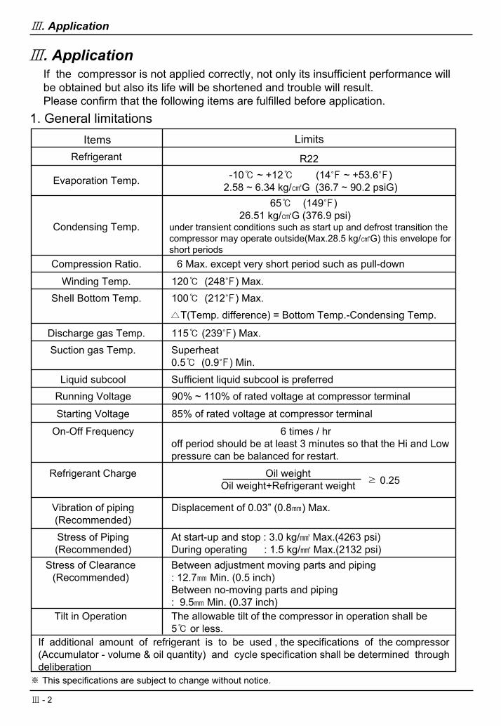
Items LimitsRefrigerant R22
Evaporation Temp. -10℃ ~ +12℃ (14℉ ~ +53.6℉)2.58 ~ 6.34 kg/㎠G (36.7 ~ 90.2 psiG)
Condensing Temp.
65℃ (149℉)26.51 kg/㎠G (376.9 psi)
under transient conditions such as start up and defrost transition the compressor may operate outside(Max.28.5 kg/㎠G) this envelope for short periods
Compression Ratio. 6 Max. except very short period such as pull-down
Winding Temp.
Discharge gas Temp. 115℃ (239℉) Max.
120℃ (248℉) Max.Shell Bottom Temp. 100℃ (212℉) Max.
△T(Temp. difference) = Bottom Temp.-Condensing Temp.
Suction gas Temp. Superheat0.5℃ (0.9℉) Min.
Liquid subcool Sufficient liquid subcool is preferredRunning Voltage
Starting Voltage
90% ~ 110% of rated voltage at compressor terminal
85% of rated voltage at compressor terminal
Refrigerant Charge Oil weightOil weight+Refrigerant weight ≥ 0.25
Stress of Piping(Recommended)
At start-up and stop : 3.0 kg/㎟ Max.(4263 psi)During operating : 1.5 kg/㎟ Max.(2132 psi)
Stress of Clearance(Recommended)
Between adjustment moving parts and piping: 12.7㎜ Min. (0.5 inch)Between no-moving parts and piping: 9.5㎜ Min. (0.37 inch)
Tilt in Operation The allowable tilt of the compressor in operation shall be5℃ or less.
If additional amount of refrigerant is to be used , the specifications of the compressor(Accumulator - volume & oil quantity) and cycle specification shall be determined through deliberation ※ This specifications are subject to change without notice.
On-Off Frequency 6 times / hroff period should be at least 3 minutes so that the Hi and Lowpressure can be balanced for restart.
Vibration of piping(Recommended)
Displacement of 0.03” (0.8㎜) Max.
Ⅲ. ApplicationIf the compressor is not applied correctly, not only its insufficient performance will be obtained but also its life will be shortened and trouble will result.Please confirm that the following items are fulfilled before application.
1. General limitations
Ⅲ - 2

Ⅲ. Application
Comp.Body
Stud BoltMountingTri-plate
Hexagon Nut
2. Compressor installationLG recommend the following mounting arrangement. (See Fig. Ⅲ- 1.)The weld bolts through the unit’s bottom pan pass through the entire length of thegrommet.The weld bolts should have either a shoulder (unthreaded portion) or a separatecylindrical sleeve assembled on to them to prevent the compression of the grommet by the hold-down locknut.
Notice : The location of the weld bolts and their perpendicularity to the unit’s bottom pan must be maintained.
Plain Washer
Grommet
Bottom Pan
Fig.Ⅲ - 1. Mounting arrangement
3. Interconnecting tube
Care should be taken in the design and production of the suction and dischargelines. It is also important that compressor vibration is not carried through them tothe evaporator and condenser where it can be amplified and transmitted to thesurrounding ambient. There is no absolute tubing design that will satisfy all possible unit variations. Generally you should keep the points in mind which stated in article 8.1 and 8.2.You should be careful not to allow infiltration of foreign matters, moisture and other harmful particles into the refrigeration circuit.
Ⅲ - 3
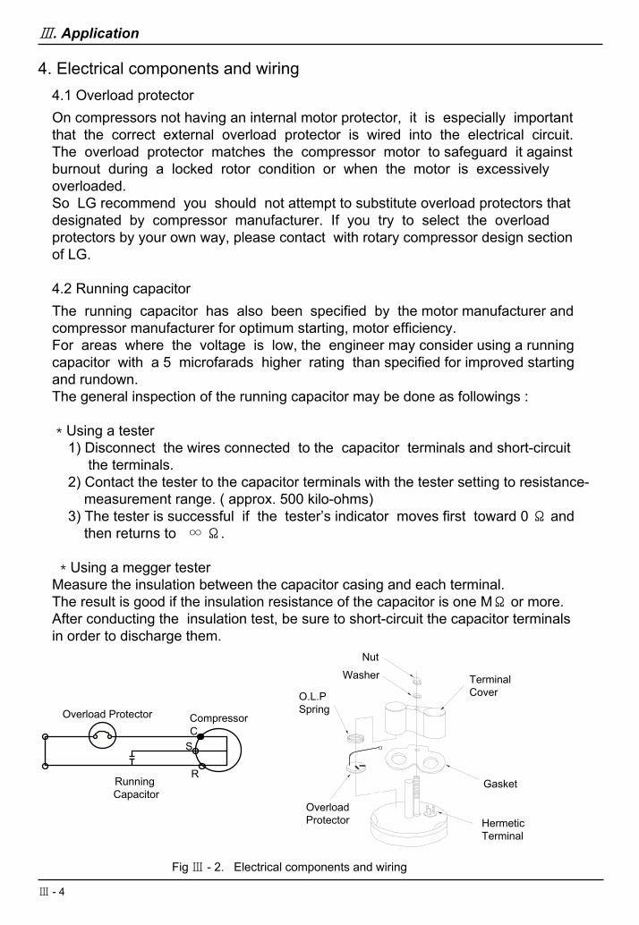
4. Electrical components and wiring4.1 Overload protectorOn compressors not having an internal motor protector, it is especially importantthat the correct external overload protector is wired into the electrical circuit. The overload protector matches the compressor motor to safeguard it against burnout during a locked rotor condition or when the motor is excessively overloaded.So LG recommend you should not attempt to substitute overload protectors thatdesignated by compressor manufacturer. If you try to select the overload protectors by your own way, please contact with rotary compressor design section of LG.
4.2 Running capacitorThe running capacitor has also been specified by the motor manufacturer andcompressor manufacturer for optimum starting, motor efficiency.For areas where the voltage is low, the engineer may consider using a runningcapacitor with a 5 microfarads higher rating than specified for improved startingand rundown.The general inspection of the running capacitor may be done as followings :
*Using a tester1) Disconnect the wires connected to the capacitor terminals and short-circuit
the terminals.2) Contact the tester to the capacitor terminals with the tester setting to resistance-
measurement range. ( approx. 500 kilo-ohms)3) The tester is successful if the tester’s indicator moves first toward 0 Ω and
then returns to ∞Ω.
*Using a megger testerMeasure the insulation between the capacitor casing and each terminal.The result is good if the insulation resistance of the capacitor is one MΩ or more.After conducting the insulation test, be sure to short-circuit the capacitor terminalsin order to discharge them.
NutWasher
O.L.PSpring
OverloadProtector Hermetic
Terminal
Gasket
TerminalCover
CompressorOverload Protector
Running Capacitor
CS
R
Fig Ⅲ - 2. Electrical components and wiring
Ⅲ. Application
Ⅲ - 4
5. General cautions
5.1 Care should be taken not to impair the control parts when the compressor is handled.
5.2 Do not leave the compressor open in the atmosphere for more than 15minutes after removing the plugs.Do not operate the compressor in the atmosphere either.
5.3 Make sure that the compressor is holding nitrogen gas.Compressor is shipped from the factory with the nitrogen gas at a pressure of 15 psiG (1㎏/㎠G) after leak test at 426 psiG ( 30㎏/㎠G).
5.4 Evacuate the refrigeration circuit to at least 750mmHg with a compound gaugefor 30 minutes.
5.5 The compressors may be damaged by replenishment of liquid refrigerant to thelow side due to the “washing away” of lubricant oil.Therefore, initial refrigerant should be charged into the unit from the high sideprocess tube of the unit.
Never charge it from the low side and suction line. The additional charge of the refrigerant to an operating unit must be done from the low side in the gas phase only.
5.6 Do not bend the pipe which is attached to the compressor.
5.7 Note the identification of compressor terminals marked on the terminal cover.
5.8 The discharge gas pressure should not be permitted to exceed 298psiG (21㎏/㎠G) during the first 10 minutes after the start of operation.
Ⅲ. Application
5.9 Compressor should be operated with a slant not more than 5 degree in any direction.
5.10 Do not use compressor its own for vacuum evacuation.
5.11 Do not apply current in vacuum condition.
5.12 Check against water infiltration into compressor terminals.
Ⅲ - 5
Ⅳ. Trouble Shooting
1. Trouble Shooting
Ⅳ - 1
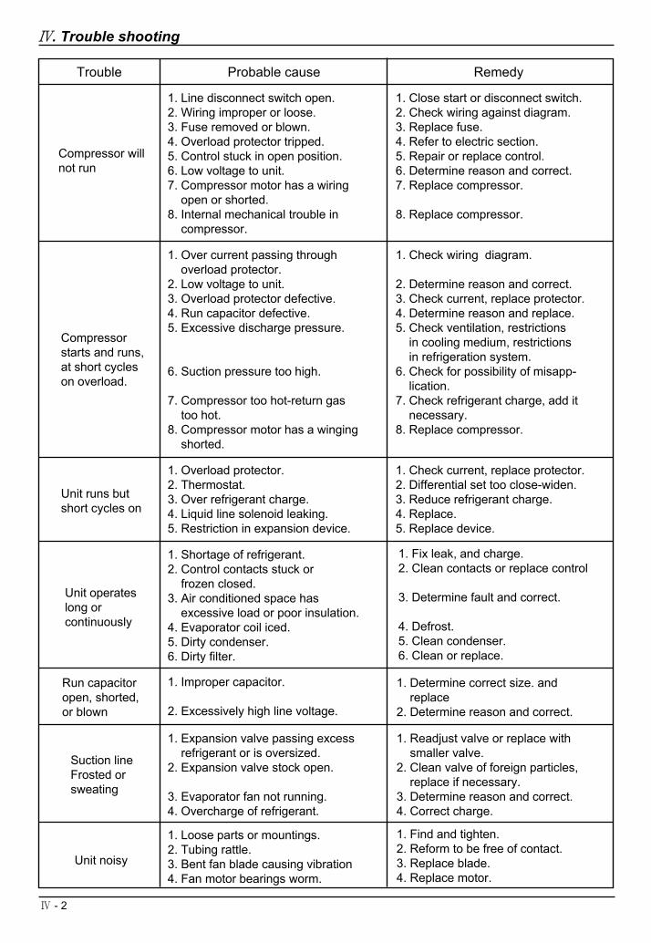
Trouble RemedyProbable cause
Compressor starts and runs,at short cycleson overload.
1. Line disconnect switch open.2. Wiring improper or loose.3. Fuse removed or blown.4. Overload protector tripped.5. Control stuck in open position.6. Low voltage to unit.7. Compressor motor has a wiring
open or shorted.8. Internal mechanical trouble in
compressor.
1. Close start or disconnect switch.2. Check wiring against diagram.3. Replace fuse.4. Refer to electric section.5. Repair or replace control.6. Determine reason and correct.7. Replace compressor.
8. Replace compressor.
Compressor willnot run
1. Over current passing throughoverload protector.
2. Low voltage to unit.3. Overload protector defective.4. Run capacitor defective.5. Excessive discharge pressure.
6. Suction pressure too high.
7. Compressor too hot-return gastoo hot.
8. Compressor motor has a wingingshorted.
1. Check wiring diagram.
2. Determine reason and correct.3. Check current, replace protector.4. Determine reason and replace.5. Check ventilation, restrictions
in cooling medium, restrictionsin refrigeration system.
6. Check for possibility of misapp-lication.
7. Check refrigerant charge, add it necessary.
8. Replace compressor.
Unit runs butshort cycles on
1. Overload protector.2. Thermostat.3. Over refrigerant charge.4. Liquid line solenoid leaking.5. Restriction in expansion device.
1. Check current, replace protector.2. Differential set too close-widen.3. Reduce refrigerant charge.4. Replace.5. Replace device.
Unit operateslong orcontinuously
1. Shortage of refrigerant.2. Control contacts stuck or
frozen closed.3. Air conditioned space has
excessive load or poor insulation.4. Evaporator coil iced.5. Dirty condenser.6. Dirty filter.
1. Fix leak, and charge.2. Clean contacts or replace control
3. Determine fault and correct.
4. Defrost.5. Clean condenser.6. Clean or replace.
Run capacitoropen, shorted,or blown
1. Improper capacitor.
2. Excessively high line voltage.
1. Determine correct size. andreplace
2. Determine reason and correct.
Suction lineFrosted orsweating
1. Expansion valve passing excessrefrigerant or is oversized.
2. Expansion valve stock open.
3. Evaporator fan not running.4. Overcharge of refrigerant.
1. Readjust valve or replace withsmaller valve.
2. Clean valve of foreign particles,replace if necessary.
3. Determine reason and correct.4. Correct charge.
Unit noisy
1. Loose parts or mountings.2. Tubing rattle.3. Bent fan blade causing vibration4. Fan motor bearings worm.
1. Find and tighten.2. Reform to be free of contact.3. Replace blade.4. Replace motor.
Ⅳ. Trouble shooting
Ⅳ - 2