Embed Size (px)
Citation preview
ARMY TM 9-2805-257-14
A IR FORCE TO 38G2-103 -2N A V Y N A V F A C P - 8 - 6 1 2 - 1 4 E
T E C H N I C A L M A N U A L
O P E R A T O R , U N I T , D I R E C T S U P P O R T ,
G E N E R A L S U P P O R T M A I N T E N A N C E M A N U A L
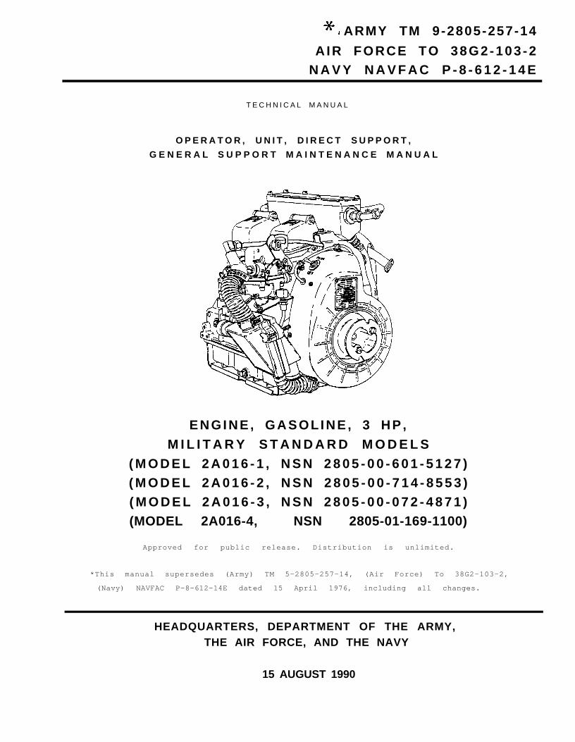
ENGINE , GASOLINE , 3 HP ,M I L I T A R Y S T A N D A R D M O D E L S
( M O D E L 2 A 0 1 6 - 1 , N S N 2 8 0 5 - 0 0 - 6 0 1 - 5 1 2 7 )( M O D E L 2 A 0 1 6 - 2 , N S N 2 8 0 5 - 0 0 - 7 1 4 - 8 5 5 3 )( M O D E L 2 A 0 1 6 - 3 , N S N 2 8 0 5 - 0 0 - 0 7 2 - 4 8 7 1 )(MODEL 2A016-4, NSN 2805-01-169-1100)
Approved for public release. Distribution is unlimited.
*This manual supersedes (Army) TM 5-2805-257-14, (Air Force) To 38G2-103-2,
(Navy) NAVFAC P-8-612-14E dated 15 April 1976, including all changes.
HEADQUARTERS, DEPARTMENT OF THE ARMY,THE AIR FORCE, AND THE NAVY
15 AUGUST 1990

ARMY TM 9-2805-257-14AIR FORCE TO 38G2-103-2
NAVY NAVFAC P-8-612-14EC3
CHANGE HEADQUARTERS, DEPARTMENTS OF ARMYTHE AIR FORCE, AND THE NAVY
NO. 3 WASHINGTON, D. C., 30 April 1997
Operator, Unit, Direct Support, General Support Maintenance Manual
ENGINE, GASOLINE, 3 HP MILITARY STANDARD MODELS(MODEL 2A016-1, NSN 2805-00-601-5127)(MODEL 2A016-2, NSN 2805-00-714-8553)(MODEL 2A016-3, NSN 2805-00-0724871)(MODEL 2A016-4, NSN 2805-01-169-1100)
DISTRIBUTION STATEMENT A: Approved for public release; distribution is unlimited
TM 9-2805-257-14/TO 38G2-103-2/NAVFAC P-8-612-14E, 15 August 1990, is changed as follows:
1. Remove and insert pages as indicated below. New or changed text material is indicated by a vertical bar in themargin. An illustration change is indicated by a miniature pointing hand.
Remove pages Insert pagesi and ii i and ii1-1 and 1-2 1-1 and 1-2----------------- F-1/(F-2 blank)
2. Retain this sheet in front of manual for reference purposes.
ARMY TM 9-2805-257-14AIR FORCE TO 38G2-103-2
NAVFAC P-8-612-14EC2
CHANGE HEADQUARTERSDEPARTMENTS OF THE ARMY, AIR FORCE AND NAVY
NO. 2 WASHINGTON, D. C., 31 July 1996
Operator, Unit, Direct Support andGeneral Support Maintenance Manual
ENGINE, GASOLINE, 3 HP,MILITARY STANDARD MODELS
(MODEL 2A016-1, NSN 2805-00-601-5127)(MODEL 2A016-2, NSN 2805-00-714-8553)(MODEL 2A016-3, NSN 2805-0-072-4871)(MODEL 2A016-4, NSN 2805-01-169-1100)
DISTRIBUTION STATEMENT A: Approved for public release; distribution is unlimited
TM 9-2805-257-14/TO 38G2-103-2/NAVFAC P-8-612-14E, 15 August 1990 is changed as follows:
1. Remove and insert pages as indicated below. New or changed text material is indicated by a vertical bar in themargin. An illustration change is indicated by a miniature pointing hand.
Remove pages Insert pagesi and ii i and ii4-3 through 4-6 4-3 through 4-64-43 and 4-44 4-43 and 4-445-15 and 5-16 5-15 and 5-16
2. Retain this sheet in front of manual for reference purposes.
ARMY TM 9-2805-257-14AIR FORCE TO 38G2-103-2NAVFAC P-8612-14E
C2
By Order of the Secretaries of the Army, Air Force and Navy:
DENNIS J. REIMERGeneral, United States Army
Official: Chief of Staff
JOEL B. HUDSONAdministrative Assistant to the
Secretary of the Army02027
RONALD R. FOGELMANGeneral, USAFChief of Staff
HENRY VICCELLIO, JR.General, USAFCommander, Air Force Materiel Command
J.E. BUFFINGTONRear Admiral, CEC, US NavyCommanderNavy Facilities EngineeringCommand
DISTRIBUTION:To be distributed in accordance with DA Form 12-25-E, block no. 0763, requirement for TM 9-2805-257-14.
ARMY TM 9–2805-257–14AIR FORCE TO 38G2-103-2
NAVFAC P-8-612-14EC1
CHANGE HEADQUARTERS,DEPARTMENTS OF THE ARMY, AIR FORCE AND NAVY
NO. 1 WASHINGTON, D. C., 20 NOVEMBER 1990
Operator, Unit, Direct Support,General Support Maintenance Manual
ENGINE, GASOLINE, 3 HP,MILITARY STANDARD MODELS
(MODEL 2A016-1, NSN 2805-00-601-5127)(MODEL 2A016-2, NSN 2805-00-714-8553)(MODEL 2A016-3, NSN 2805-00-72-4871)(MODEL 2A016-4, NSN 2805-01-169-1100)
Approved for public release; distribution is unlimited
TM 9–2805–257–14/TO 38G2–103–2/NAVFAC P–8–612–14E, 15 August 1990 is changed asfollows:
1. Remove and insert pages as indicated below. New or changed text material is indicated by avertical bar in the margin. An illustration change is indicated by a miniature pointing hand.
Remove pages Insert pages
4-3 and 4-4 4-3 and 4-4
2. Retain this sheet in front of manual for reference purposes.
ARMY TM 9-2805-257-14AIR FORCE TO 38G2-103-2NAVFAC P-8-612-14E
C 1
By Order of the Secretaries of the Army , Air Force, and Navy:
CARL E. VUONOGeneral, United States Army
Chief of Staff
Official:THOMAS F. SIKORA
Brigadier General, United States ArmyThe Adjutant General
MERRILL A. McPEAKGeneral USAFChief of Staff
Official:CHARLES C. MCDONALD
General, USAFCommander, Air Force Logistics Command
DAVID E. BUTTORFFRear Admiral, CEC, US Navy
CommanderNavy Facilities Engineering Command
D i s t r i b u t i o n :To be distributed in accordance with DA Form 12–25E, (qty rqr block no. 0763)
WARNING
ARMY TM 9-2805-257-14AIR FORCE TO 38G2-103-2
NAVY NAVFAC P-8-612-14E
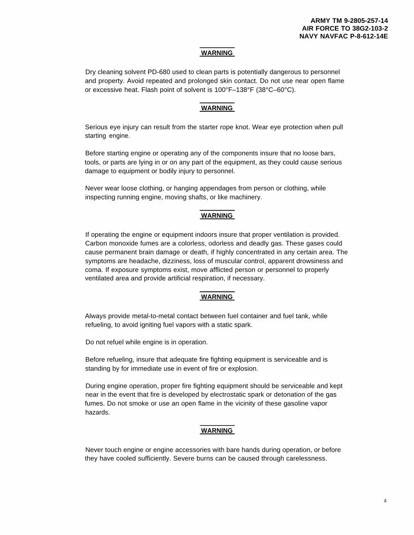
Dry cleaning solvent PD-680 used to clean parts is potentially dangerous to personneland property. Avoid repeated and prolonged skin contact. Do not use near open flameor excessive heat. Flash point of solvent is 100°F–138°F (38°C–60°C).
WARNING
Serious eye injury can result from the starter rope knot. Wear eye protection when pullstarting engine.
Before starting engine or operating any of the components insure that no loose bars,tools, or parts are lying in or on any part of the equipment, as they could cause seriousdamage to equipment or bodily injury to personnel.
Never wear loose clothing, or hanging appendages from person or clothing, whileinspecting running engine, moving shafts, or like machinery.
WARNING
If operating the engine or equipment indoors insure that proper ventilation is provided.Carbon monoxide fumes are a colorless, odorless and deadly gas. These gases couldcause permanent brain damage or death, if highly concentrated in any certain area. Thesymptoms are headache, dizziness, loss of muscular control, apparent drowsiness andcoma. If exposure symptoms exist, move afflicted person or personnel to properlyventilated area and provide artificial respiration, if necessary.
WARNING
Always provide metal-to-metal contact between fuel container and fuel tank, whilerefueling, to avoid igniting fuel vapors with a static spark.
Do not refuel while engine is in operation.
Before refueling, insure that adequate fire fighting equipment is serviceable and isstanding by for immediate use in event of fire or explosion.
During engine operation, proper fire fighting equipment should be serviceable and keptnear in the event that fire is developed by electrostatic spark or detonation of the gasfumes. Do not smoke or use an open flame in the vicinity of these gasoline vaporhazards.
WARNING
a
Never touch engine or engine accessories with bare hands during operation, or beforethey have cooled sufficiently. Severe burns can be caused through carelessness.
ARMY TM 9-2805-257-14AIR FORCE TO 38G2-103-2NAVY NAVFAC P-8-612-14E
b
WARNING
Do not touch the ignition system harness during starting or while in operation. Severeshocks or burns could result, and personnel may be seriously injured.
Disconnect the spark plug cables prior to engine maintenance to prevent accidentalstarting and severe shock.
WARNING
Operation of the equipment presents a noise hazard to personnel in the area. The noiselevel exceeds the allowable limits for unprotected personnel. Wear ear muffs or ear plugswhich were fitted by a trained professional.
WARNING
Use extreme care when removing coil clamps. Flying clamps can cause serious eyeinjury. Cover work area with rag or hand when removing clamps
*ARMY TM 9-2805-257-14AIR FORCE TO 38G2-103-2
NAVY NAVFAC P-8-612-14E
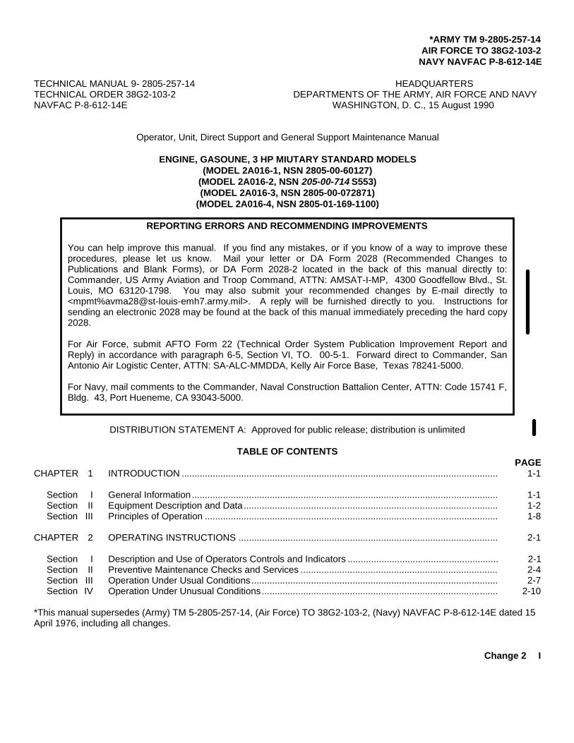
TECHNICAL MANUAL 9- 2805-257-14 HEADQUARTERSTECHNICAL ORDER 38G2-103-2 DEPARTMENTS OF THE ARMY, AIR FORCE AND NAVYNAVFAC P-8-612-14E WASHINGTON, D. C., 15 August 1990
Operator, Unit, Direct Support and General Support Maintenance Manual
ENGINE, GASOUNE, 3 HP MIUTARY STANDARD MODELS(MODEL 2A016-1, NSN 2805-00-60127)
(MODEL 2A016-2, NSN 205-00-714 S553)(MODEL 2A016-3, NSN 2805-00-072871)
(MODEL 2A016-4, NSN 2805-01-169-1100)
REPORTING ERRORS AND RECOMMENDING IMPROVEMENTS
You can help improve this manual. If you find any mistakes, or if you know of a way to improve theseprocedures, please let us know. Mail your letter or DA Form 2028 (Recommended Changes toPublications and Blank Forms), or DA Form 2028-2 located in the back of this manual directly to:Commander, US Army Aviation and Troop Command, ATTN: AMSAT-I-MP, 4300 Goodfellow Blvd., St.Louis, MO 63120-1798. You may also submit your recommended changes by E-mail directly to<mpmt%[email protected]>. A reply will be furnished directly to you. Instructions forsending an electronic 2028 may be found at the back of this manual immediately preceding the hard copy2028.
For Air Force, submit AFTO Form 22 (Technical Order System Publication Improvement Report andReply) in accordance with paragraph 6-5, Section VI, TO. 00-5-1. Forward direct to Commander, SanAntonio Air Logistic Center, ATTN: SA-ALC-MMDDA, Kelly Air Force Base, Texas 78241-5000.
For Navy, mail comments to the Commander, Naval Construction Battalion Center, ATTN: Code 15741 F,Bldg. 43, Port Hueneme, CA 93043-5000.
DISTRIBUTION STATEMENT A: Approved for public release; distribution is unlimited
TABLE OF CONTENTSPAGE
CHAPTER 1 INTRODUCTION .......................................................................................................................... 1-1
Section I General Information ...................................................................................................................... 1-1Section II Equipment Description and Data.................................................................................................. 1-2Section III Principles of Operation ................................................................................................................. 1-8
CHAPTER 2 OPERATING INSTRUCTIONS .................................................................................................... 2-1
Section I Description and Use of Operators Controls and Indicators .......................................................... 2-1Section II Preventive Maintenance Checks and Services ............................................................................ 2-4Section III Operation Under Usual Conditions............................................................................................... 2-7Section IV Operation Under Unusual Conditions........................................................................................... 2-10
*This manual supersedes (Army) TM 5-2805-257-14, (Air Force) TO 38G2-103-2, (Navy) NAVFAC P-8-612-14E dated 15April 1976, including all changes.
Change 2 I
ARMY TM 9-2805-257-14AIR FORCE TO 38G2-103-2NAVY NAVFAC P-8-612-14E
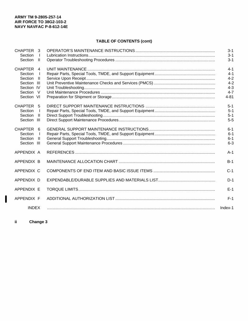
TABLE OF CONTENTS (cont)
CHAPTER 3 OPERATOR’S MAINTENANCE INSTRUCTIONS ....................................................................... 3-1Section I Lubrication Instructions................................................................................................................. 3-1Section II Operator Troubleshooting Procedures ......................................................................................... 3-1
CHAPTER 4 UNIT MAINTENANCE .................................................................................................................. 4-1Section I Repair Parts, Special Tools, TMDE, and Support Equipment ...................................................... 4-1Section II Service Upon Receipt ................................................................................................................... 4-2Section III Unit Preventive Maintenance Checks and Services (PMCS) ....................................................... 4-2Section IV Unit Troubleshooting..................................................................................................................... 4-3Section V Unit Maintenance Procedures ...................................................................................................... 4-7Section VI Preparation for Shipment or Storage............................................................................................ 4-81
CHAPTER 5 DIRECT SUPPORT MAINTENANCE INSTRUCTIONS .............................................................. 5-1Section I Repair Parts, Special Tools, TMDE, and Support Equipment ...................................................... 5-1Section II Direct Support Troubleshooting.................................................................................................... 5-1Section III Direct Support Maintenance Procedures...................................................................................... 5-5
CHAPTER 6 GENERAL SUPPORT MAINTENANCE INSTRUCTIONS........................................................... 6-1Section I Repair Parts, Special Tools, TMDE, and Support Equipment ...................................................... 6-1Section II General Support Troubleshooting................................................................................................. 6-1Section III General Support Maintenance Procedures .................................................................................. 6-3
APPENDIX A REFERENCES ............................................................................................................................. A-1
APPENDIX B MAINTENANCE ALLOCATION CHART ...................................................................................... B-1
APPENDIX C COMPONENTS OF END ITEM AND BASIC ISSUE ITEMS ....................................................... C-1
APPENDIX D EXPENDABLE/DURABLE SUPPLIES AND MATERIALS LIST................................................... D-1
APPENDIX E TORQUE LIMITS.......................................................................................................................... E-1
APPENDIX F ADDITIONAL AUTHORIZATION LIST ......................................................................................... F-1
INDEX ...................................................................................................................................................... Index-1
ii Change 3
ARMY TM 9-2805-257-14AIR FORCE TO 38G2-103-2
NAVY NAVFAC P-8-612-14E
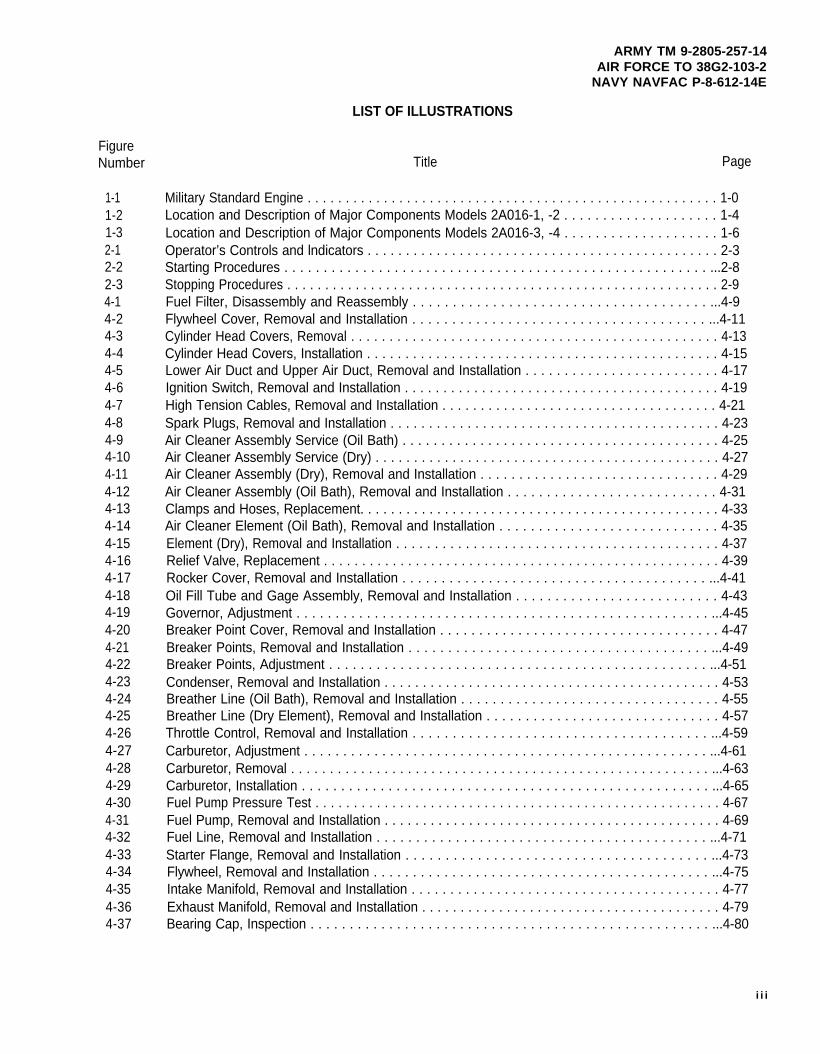
LIST OF ILLUSTRATIONS
FigureNumber
1-11-21-32-12-22-34-14-24-34-44-54-64-74-84-94-104-114-124-134-144-154-164-174-184-194-204-214-224-234-244-254-264-274-284-294-304-314-324-334-344-354-364-37
Title Page
Military Standard Engine . . . . . . . . . . . . . . . . . . . . . . . . . . . . . . . . . . . . . . . . . . . . . . . . . . . . . . 1-0Location and Description of Major Components Models 2A016-1, -2 . . . . . . . . . . . . . . . . . . . . 1-4Location and Description of Major Components Models 2A016-3, -4 . . . . . . . . . . . . . . . . . . . . 1-6Operator’s Controls and lndicators . . . . . . . . . . . . . . . . . . . . . . . . . . . . . . . . . . . . . . . . . . . . . . 2-3Starting Procedures . . . . . . . . . . . . . . . . . . . . . . . . . . . . . . . . . . . . . . . . . . . . . . . . . . . . . . ...2-8Stopping Procedures . . . . . . . . . . . . . . . . . . . . . . . . . . . . . . . . . . . . . . . . . . . . . . . . . . . . . . . . . 2-9Fuel Filter, Disassembly and Reassembly . . . . . . . . . . . . . . . . . . . . . . . . . . . . . . . . . . . . . ...4-9Flywheel Cover, Removal and Installation . . . . . . . . . . . . . . . . . . . . . . . . . . . . . . . . . . . . . ...4-11Cylinder Head Covers, Removal . . . . . . . . . . . . . . . . . . . . . . . . . . . . . . . . . . . . . . . . . . . . . . . . 4-13Cylinder Head Covers, Installation . . . . . . . . . . . . . . . . . . . . . . . . . . . . . . . . . . . . . . . . . . . . . . 4-15Lower Air Duct and Upper Air Duct, Removal and Installation . . . . . . . . . . . . . . . . . . . . . . . . . 4-17Ignition Switch, Removal and Installation . . . . . . . . . . . . . . . . . . . . . . . . . . . . . . . . . . . . . . . . . 4-19High Tension Cables, Removal and Installation . . . . . . . . . . . . . . . . . . . . . . . . . . . . . . . . . . . . 4-21Spark Plugs, Removal and Installation . . . . . . . . . . . . . . . . . . . . . . . . . . . . . . . . . . . . . . . . . . . 4-23Air Cleaner Assembly Service (Oil Bath) . . . . . . . . . . . . . . . . . . . . . . . . . . . . . . . . . . . . . . . . . 4-25Air Cleaner Assembly Service (Dry) . . . . . . . . . . . . . . . . . . . . . . . . . . . . . . . . . . . . . . . . . . . . . 4-27Air Cleaner Assembly (Dry), Removal and Installation . . . . . . . . . . . . . . . . . . . . . . . . . . . . . . . 4-29Air Cleaner Assembly (Oil Bath), Removal and Installation . . . . . . . . . . . . . . . . . . . . . . . . . . . 4-31Clamps and Hoses, Replacement. . . . . . . . . . . . . . . . . . . . . . . . . . . . . . . . . . . . . . . . . . . . . . . 4-33Air Cleaner Element (Oil Bath), Removal and Installation . . . . . . . . . . . . . . . . . . . . . . . . . . . . 4-35Element (Dry), Removal and Installation . . . . . . . . . . . . . . . . . . . . . . . . . . . . . . . . . . . . . . . . . . 4-37Relief Valve, Replacement . . . . . . . . . . . . . . . . . . . . . . . . . . . . . . . . . . . . . . . . . . . . . . . . . . . . 4-39Rocker Cover, Removal and Installation . . . . . . . . . . . . . . . . . . . . . . . . . . . . . . . . . . . . . . . ...4-41Oil Fill Tube and Gage Assembly, Removal and Installation . . . . . . . . . . . . . . . . . . . . . . . . . . 4-43Governor, Adjustment . . . . . . . . . . . . . . . . . . . . . . . . . . . . . . . . . . . . . . . . . . . . . . . . . . . . . ...4-45Breaker Point Cover, Removal and Installation . . . . . . . . . . . . . . . . . . . . . . . . . . . . . . . . . . . . 4-47Breaker Points, Removal and Installation . . . . . . . . . . . . . . . . . . . . . . . . . . . . . . . . . . . . . . ...4-49Breaker Points, Adjustment . . . . . . . . . . . . . . . . . . . . . . . . . . . . . . . . . . . . . . . . . . . . . . . . ...4-51Condenser, Removal and Installation . . . . . . . . . . . . . . . . . . . . . . . . . . . . . . . . . . . . . . . . . . . . 4-53Breather Line (Oil Bath), Removal and Installation . . . . . . . . . . . . . . . . . . . . . . . . . . . . . . . . . 4-55Breather Line (Dry Element), Removal and Installation . . . . . . . . . . . . . . . . . . . . . . . . . . . . . . 4-57Throttle Control, Removal and Installation . . . . . . . . . . . . . . . . . . . . . . . . . . . . . . . . . . . . . ...4-59Carburetor, Adjustment . . . . . . . . . . . . . . . . . . . . . . . . . . . . . . . . . . . . . . . . . . . . . . . . . . . . ...4-61Carburetor, Removal . . . . . . . . . . . . . . . . . . . . . . . . . . . . . . . . . . . . . . . . . . . . . . . . . . . . . . ...4-63Carburetor, Installation . . . . . . . . . . . . . . . . . . . . . . . . . . . . . . . . . . . . . . . . . . . . . . . . . . . . ...4-65Fuel Pump Pressure Test . . . . . . . . . . . . . . . . . . . . . . . . . . . . . . . . . . . . . . . . . . . . . . . . . . . . . 4-67Fuel Pump, Removal and Installation . . . . . . . . . . . . . . . . . . . . . . . . . . . . . . . . . . . . . . . . . . . . 4-69Fuel Line, Removal and Installation . . . . . . . . . . . . . . . . . . . . . . . . . . . . . . . . . . . . . . . . . . ...4-71Starter Flange, Removal and Installation . . . . . . . . . . . . . . . . . . . . . . . . . . . . . . . . . . . . . . ...4-73Flywheel, Removal and Installation . . . . . . . . . . . . . . . . . . . . . . . . . . . . . . . . . . . . . . . . . . . ...4-75Intake Manifold, RemovaI and Installation . . . . . . . . . . . . . . . . . . . . . . . . . . . . . . . . . . . . . . . . 4-77Exhaust Manifold, Removal and Installation . . . . . . . . . . . . . . . . . . . . . . . . . . . . . . . . . . . . . . . 4-79Bearing Cap, Inspection . . . . . . . . . . . . . . . . . . . . . . . . . . . . . . . . . . . . . . . . . . . . . . . . . . . ...4-80
i i i
ARMY TM 9-2805-257-14AIR FORCE TO 38G2-103-2NAVY NAVFAC P-8-612-14E
LIST OF ILLUSTRATIONS (cont)
FigureNumber
5-15-25-35-45-55-65-75-85-95-105-115-125-135-145-155-165-175-185-195-205-215-225-235-245-255-265-276-16-26-36-46-56-66-76-8
Title Page
Oil Pan, Removal and lnstallation . . . . . . . . . . . . . . . . . . . . . . . . . . . . . . . . . . . . . . . . . . . . . . . 5-7Governor Assembly, Removal . . . . . . . . . . . . . . . . . . . . . . . . . . . . . . . . . . . . . . . . . . . . . . ...5-9Governor Repair Breakerless Ignition . . . . . . . . . . . . . . . . . . . . . . . . . . . . . . . . . . . . . . . . . . . . 5-11Governor Repair Breaker Point Ignition . . . . . . . . . . . . . . . . . . . . . . . . . . . . . . . . . . . . . . . ...5-13Governor Assembly, Installation. . . . . . . . . . . . . . . . . . . . . . . . . . . . . . . . . . . . . . . . . . . . . . . . 5-15Ignition Timing . . . . . . . . . . . . . . . . . . . . . . . . . . . . . . . . . . . . . . . . . . . . . . . . . . . . . . . . . . . ...5-17Ignition Control Unit, Removal and Installation . . . . . . . . . . . . . . . . . . . . . . . . . . . . . . . . . . . . . 5-19Transformer, Removal and Installation . . . . . . . . . . . . . . . . . . . . . . . . . . . . . . . . . . . . . . . . . . . 5-21Ignition Module, Removal and Installation . . . . . . . . . . . . . . . . . . . . . . . . . . . . . . . . . . . . . ...5-23Low Voltage Cable, Removal and Installation . . . . . . . . . . . . . . . . . . . . . . . . . . . . . . . . . . . . . . 5-25Cylinder Head, Removal . . . . . . . . . . . . . . . . . . . . . . . . . . . . . . . . . . . . . . . . . . . . . . . . . . . ...5-27Cylinder Head Assembly, Repair. . . . . . . . . . . . . . . . . . . . . . . . . . . . . . . . . . . . . . . . . . . . ...5-29Cylinder Head, Installation . . . . . . . . . . . . . . . . . . . . . . . . . . . . . . . . . . . . . . . . . . . . . . . . . ...5-31Rockers, Removal and Installation . . . . . . . . . . . . . . . . . . . . . . . . . . . . . . . . . . . . . . . . . . . . . . 5-33Valve, Adjustment . . . . . . . . . . . . . . . . . . . . . . . . . . . . . . . . . . . . . . . . . . . . . . . . . . . . . . . . ...5-35lntake and Exhaust Valve, Removal and Installation . . . . . . . . . . . . . . . . . . . . . . . . . . . . . . . . 5-37Piston and Connecting Rod, Removal . . . . . . . . . . . . . . . . . . . . . . . . . . . . . . . . . . . . . . . . . . . 5-39Piston and Connecting Rod, Repair . . . . . . . . . . . . . . . . . . . . . . . . . . . . . . . . . . . . . . . . . . . . . 5-41Piston and Connecting Rod, Installation . . . . . . . . . . . . . . . . . . . . . . . . . . . . . . . . . . . . . . . . . . 5-43Rotating Magnet, Removal and Installation . . . . . . . . . . . . . . . . . . . . . . . . . . . . . . . . . . . . . . . 5-45Coil, Removal and Installation . . . . . . . . . . . . . . . . . . . . . . . . . . . . . . . . . . . . . . . . . . . . . . . . . 5-47Flywheel Side Oil Seal, Removal and Installation . . . . . . . . . . . . . . . . . . . . . . . . . . . . . . . . . ..5-49Noise Suppression Filter, Removal and Installation . . . . . . . . . . . . . . . . . . . . . . . . . . . . . . . . . 5-51Crankshaft Side Oil SeaI, Removal and Installation . . . . . . . . . . . . . . . . . . . . . . . . . . . . . . . . . 5-53Compression Test . . . . . . . . . . . . . . . . . . . . . . . . . . . . . . . . . . . . . . . . . . . . . . . . . . . . . . . . ...5-55Breakerless Ignition System Wiring Diagram . . . . . . . . . . . . . . . . . . . . . . . . . . . . . . . . . . . . . . 5-56Breaker Point Ignition Wiring Diagram . . . . . . . . . . . . . . . . . . . . . . . . . . . . . . . . . . . . . . . . . . . 5-57Bearing Cap, Removal and Repair . . . . . . . . . . . . . . . . . . . . . . . . . . . . . . . . . . . . . . . . . . . . . . 6-5Bearing Cap, Installation . . . . . . . . . . . . . . . . . . . . . . . . . . . . . . . . . . . . . . . . . . . . . . . . . . . . . . 6-7Crankshaft, Removal . . . . . . . . . . . . . . . . . . . . . . . . . . . . . . . . . . . . . . . . . . . . . . . . . . . . . . . . 6-8Crankshaft, Inspection . . . . . . . . . . . . . . . . . . . . . . . . . . . . . . . . . . . . . . . . . . . . . . . . . . . . . . . 6-9Crankshaft, lnstallation . . . . . . . . . . . . . . . . . . . . . . . . . . . . . . . . . . . . . . . . . . . . . . . . . . . . . . . 6-11Camshaft, Removal and lnspection . . . . . . . . . . . . . . . . . . . . . . . . . . . . . . . . . . . . . . . . . . . . . 6-13Camshaft, Installation . . . . . . . . . . . . . . . . . . . . . . . . . . . . . . . . . . . . . . . . . . . . . . . . . . . . . . . . 6-15Crankcase, Repair . . . . . . . . . . . . . . . . . . . . . . . . . . . . . . . . . . . . . . . . . . . . . . . . . . . . . . . ...6-17
iv/(v blank)

ARMY TM 9-2805-257-14AIR FORCE TO 38G2-103-2NAVY NAVFAC P-8-612-14E
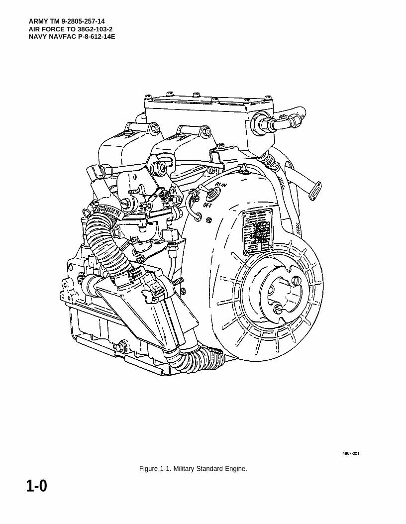
Figure 1-1. Military Standard Engine.
1-0
ARMY TM 9-2805-257-14AIR FORCE TO 38G2-103-2
NAVY NAVFAC P-8-612-14E
CHAPTER 1
INTRODUCTION
Page
OVERVIEW . . . . . . . . . . . . . . . . . . . . . . . . . . . . . . . . . . . . . . . . . . . . . . . . . . . . . . . . . . . . . . . ...1-1Section I. General Information . . . . . . . . . . . . . . . . . . . . . . . . . . . . . . . . . . . . . . . . . . . . . . . ...1-1Section Il. Equipment Description and Data. . . . . . . . . . . . . . . . . . . . . . . . . . . . . . . . . . . . . ...1-2Section Ill. Principles of Operation . . . . . . . . . . . . . . . . . . . . . . . . . . . . . . . . . . . . . . . . . . . . . ...1-8
OVERVIEW
This chapter contains general information pertaining to 3 HP Military Standard Engine and its components.
Section I. GENERAL INFORMATION
Paragraph Page
1-1 Scope . . . . . . . . . . . . . . . . . . . . . . . . . . . . . . . . . . . . . . . . . . . . . . . . . . . . . . . . . . . . . . ...1-11-2 Consolidated lndex of Army Publications and Blank Forms . . . . . . . . . . . . . . . . . . . . . . . 1-11-3 Maintenance Forms, Records, and Reports . . . . . . . . . . . . . . . . . . . . . . . . . . . . . . . . ...1-11-4 Reporting Equipment Improvement Recommendations (EIR’s) . . . . . . . . . . . . . . . . . . . . 1-21-5 Destruction of Army Materiel to Prevent Enemy Use . . . . . . . . . . . . . . . . . . . . . . . . . . . . . 1-21-6 Preparation for Storage and Shipment . . . . . . . . . . . . . . . . . . . . . . . . . . . . . . . . . . . . ...1-21-7 Glossary . . . . . . . . . . . . . . . . . . . . . . . . . . . . . . . . . . . . . . . . . . . . . . . . . . . . . . . . . . . . ...1-2
1-1. Scope. This manual contains operator, unit, direct support and general support maintenance for the 3 HPMilitary Standard Engine, Models 2A016-1, -2, -3, and -4 (figures 1-1, 1-2, and 1-3).
1-2. Consolidated lndex of Army Publications and Blank Forms. Refer to the latest issue of DAPAM 25-30 to determine whether there are new editions, changes, or additional publications pertaining to theequipment
1-3. Maintenance Forms, Records and Reports.
a. Reports of Maintenance and Unsatisfactory Equipment. Department of the Army forms and proceduresused for equipment maintenance will be those prescribed by DA Pam 738-750, as contained in MaintenanceManagement Update. Air Force personnel will use AFR 66-1 (Air Force Maintenance Management Policy) formaintenance reporting and TO-00-35D54 for unsatisfactory equipment reporting. Navy personnel will reportmaintenance performed utilizing the Maintenance Data Collection Subsystem (MDCS) IAW OPNAVINST 4790.2,Vol 3 and unsatisfactory material/conditions (UR submissions) IAW OPNAVINST 4790.2, Vol 2, chapter 17.
b. Reporting of Item and Packaging Discrepancies. Fill out and forward SF 364 (Report of Discrepancy(ROD)) as prescribed in AR 735-11-2/DLAR 414-.55/SECNAVlNST 4355.18/AFR 400-54/MCO 4430.3J.
1-1
ARMY TM 9-2805-257-14AIR FORCE TO 38G2-103-2NAVY NACFAC P-8-612-14E
c. Transportation Discrepancy, Report (TDR) (SF 361). Fill out and forward Transportation Discrepancy Report(TDR) (SF 361) as prescribed in AR 55-28/NAVUSPINST 4610.33C/AFR 75-18/MCO P4610.19D/DLAR 4500.1 5.
1-4. Reporting Equipment Improvement Recommendations (EIR).
a. Army. If your Military Standard Engine needs improvement, let us know. Send us an EIR. You, the user, are theonly one who can tell us what you don’t like about your equipment. Let us know why you don’t like the design orperformance. Put it on an SF 368 (Product Quality Deficiency Report). Mail it to us at: Commander, U.S. Army Aviationand Troop Command, A’TN: AMSATIMDO, 4300 Goodfellow Boulevard, St. Louis, MO 631201798. We will send you areply.
b. Air Force. Air Force personnel are encouraged to submit EIR’s in accordance with AFR 900-4.
c. Navy. Navy personnel are encouraged to submit EIR’s through their local Beneficial Suggestion Program.
1-5. Destruction of Army Materiel to Prevent Enemy Use. Refer to TM 750-244-3 for procedures to destroyequipment to prevent enemy use.
1-6. Preparation for Storage or Shipment. RefertoChapter4, Section VI, andTB740-97-2 for procedure to place theequipment into storage.
1-7. Glossary. Not applicable.
Section II. EQUIPMENT DESCRIPTION AND DATA
Paragraph Page
1-8 Equipment Characteristics, Capabilities and Features................................................................. 1-2
1-9 Location and Description of Major Components (Models 1 A08-1, -2)......................................... 1-3
1-10 Location and Description of Major Components (Models 1A08-3, -4).......................................... 1-5
1-11 Equipment Data ............................................................................................................................ 1-7
1-12 Differences Between Models ....................................................................................................... 1-8
1-13 Safety, Care, and Handling........................................................................................................... 1-8
1-8. Equipment Characteristics, Capabilities and Features. The Military Standard Engine is an air cooled, singlecylinder, four cycle gasoline engine. The engine is capable of developing 3 HP at 3600 RPM.
1-2 Change 3
ARMY TM 9-2805-257-14AIR FORCE TO 38G2-103-2
NAVY NAVFAC P-8-612-14E
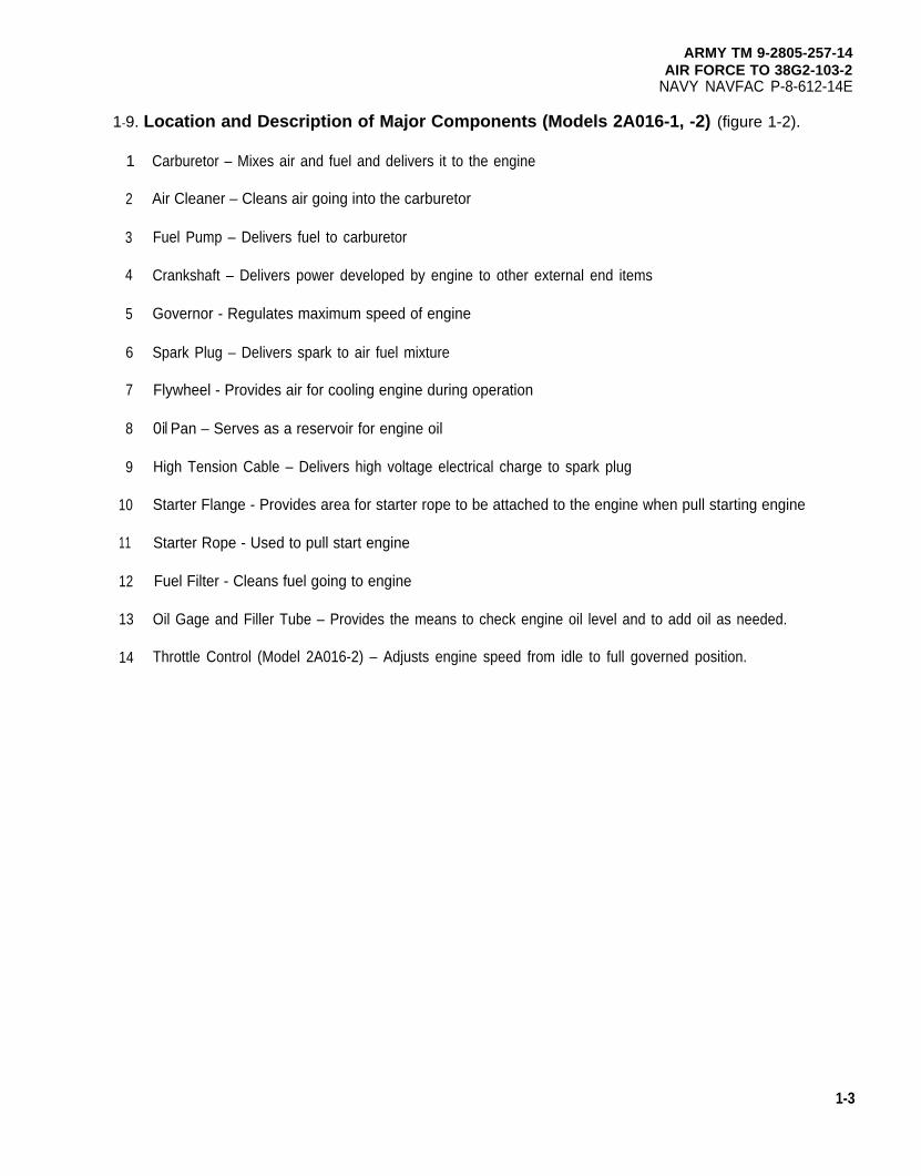
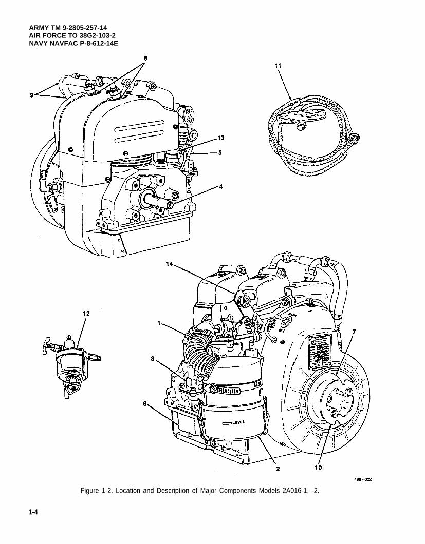
1-9. Location and Description of Major Components (Models 2A016-1, -2) (figure 1-2).
1
2
3
4
5
6
7
8
9
10
11
12
13
14
Carburetor – Mixes air and fuel and delivers it to the engine
Air Cleaner – Cleans air going into the carburetor
Fuel Pump – Delivers fuel to carburetor
Crankshaft – Delivers power developed by engine to other external end items
Governor - Regulates maximum speed of engine
Spark Plug – Delivers spark to air fuel mixture
Flywheel - Provides air for cooling engine during operation
Oil Pan – Serves as a reservoir for engine oil
High Tension Cable – Delivers high voltage electrical charge to spark plug
Starter Flange - Provides area for starter rope to be attached to the engine when pull starting engine
Starter Rope - Used to pull start engine
Fuel Filter - Cleans fuel going to engine
Oil Gage and Filler Tube – Provides the means to check engine oil level and to add oil as needed.
Throttle Control (Model 2A016-2) – Adjusts engine speed from idle to full governed position.
1-3
ARMY TM 9-2805-257-14AIR FORCE TO 38G2-103-2NAVY NAVFAC P-8-612-14E
Figure 1-2. Location and Description of Major Components Models 2A016-1, -2.
1-4
ARMY TM 9-2805-257-14AIR FORCE TO 38G2-103-2
NAVY NAVFAC P-8-612-14E
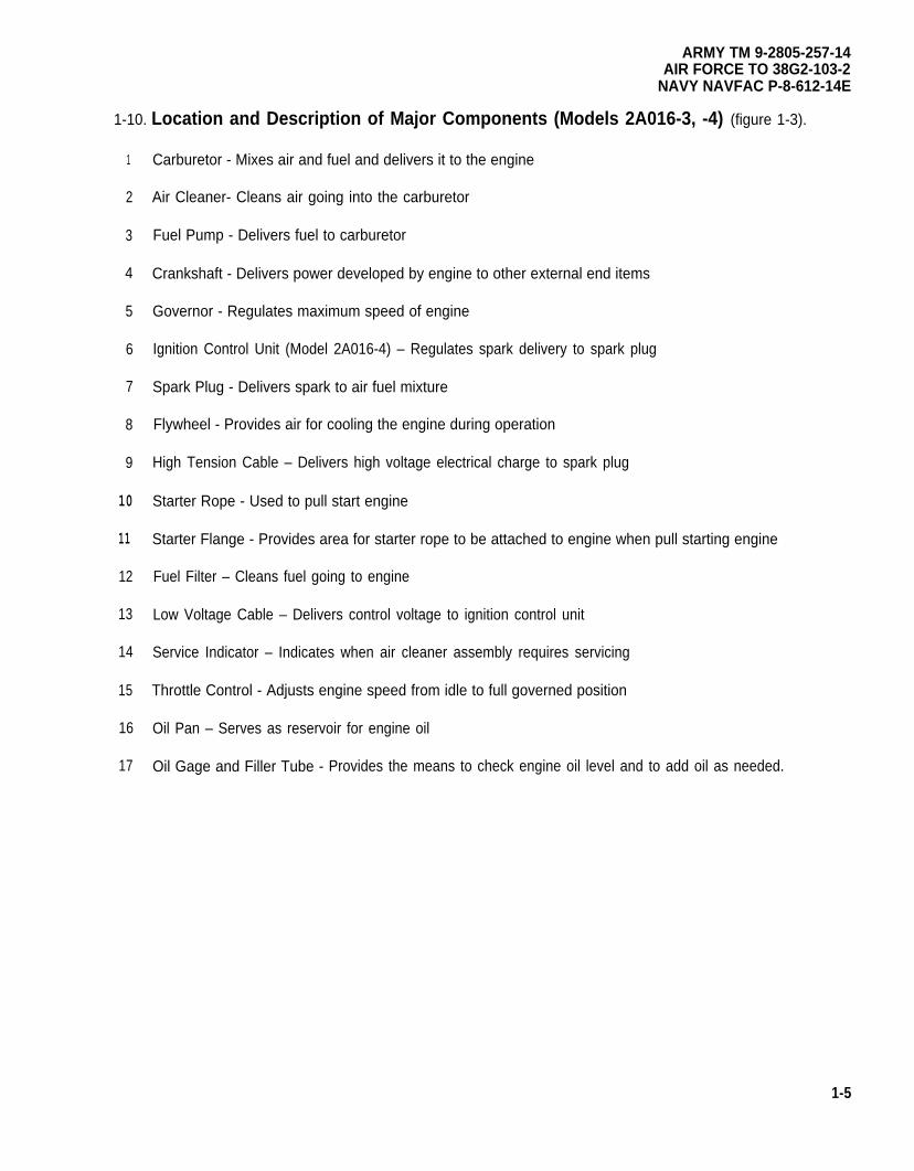
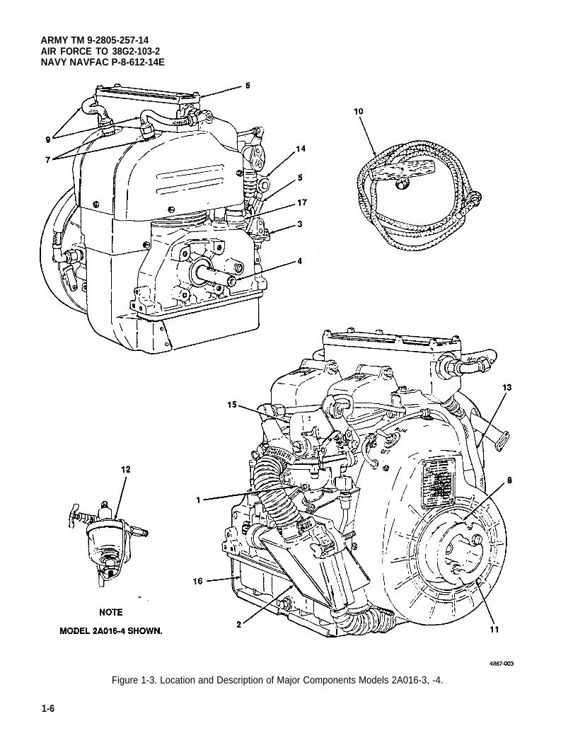
1-10. Location and Description of Major Components (Models 2A016-3, -4) (figure 1-3).
1
2
3
4
5
6
7
8
9
10
11
12
13
14
15
16
17
Carburetor - Mixes air and fuel and delivers it to the engine
Air Cleaner- Cleans air going into the carburetor
Fuel Pump - Delivers fuel to carburetor
Crankshaft - Delivers power developed by engine to other external end items
Governor - Regulates maximum speed of engine
Ignition Control Unit (Model 2A016-4) – Regulates spark delivery to spark plug
Spark Plug - Delivers spark to air fuel mixture
Flywheel - Provides air for cooling the engine during operation
High Tension Cable – Delivers high voltage electrical charge to spark plug
Starter Rope - Used to pull start engine
Starter Flange - Provides area for starter rope to be attached to engine when pull starting engine
Fuel Filter – Cleans fuel going to engine
Low Voltage Cable – Delivers control voltage to ignition control unit
Service Indicator – Indicates when air cleaner assembly requires servicing
Throttle Control - Adjusts engine speed from idle to full governed position
Oil Pan – Serves as reservoir for engine oil
Oil Gage and Filler Tube - Provides the means to check engine oil level and to add oil as needed.
1-5
ARMY TM 9-2805-257-14AIR FORCE TO 38G2-103-2NAVY NAVFAC P-8-612-14E
Figure 1-3. Location and Description of Major Components Models 2A016-3, -4.
1-6
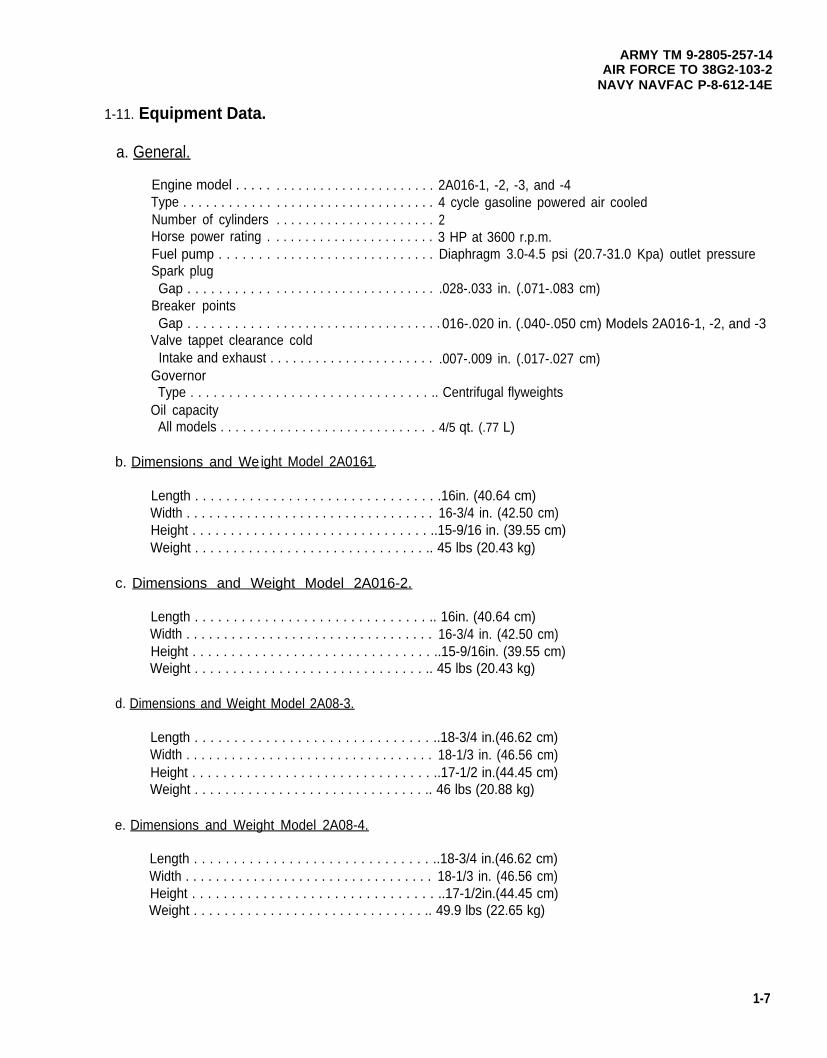
1-11. Equipment Data.
a. General.
Engine model . . . . .Type . . . . . . . . . . . .Number of cylindersHorse power rating .Fuel pump . . . . . . .Spark plugGap . . . . . . . . . . .
Breaker pointsGap . . . . . . . . . . .
ARMY TM 9-2805-257-14AIR FORCE TO 38G2-103-2
NAVY NAVFAC P-8-612-14E
. . . . . . . . . . . . . . . . . . . . . . 2A016-1, -2, -3, and -4
. . . . . . . . . . . . . . . . . . . . . . 4 cycle gasoline powered air cooled
. . . . . . . . . . . . . . . . . . . . . . 2
. . . . . . . . . . . . . . . . . . . . . . 3 HP at 3600 r.p.m.
. . . . . . . . . . . . . . . . . . . . . . Diaphragm 3.0-4.5 psi (20.7-31.0 Kpa) outlet pressure
. . . . . . . . . . . . . . . . . . . . . . .028-.033 in. (.071-.083 cm)
. . . . . . . . . . . . . . . . . . . . . . . 016-.020 in. (.040-.050 cm) Models 2A016-1, -2, and -3Valve tappet clearance cold
Intake and exhaust . . . . . . . . . . . . . . . . . . . . . . .007-.009 in. (.017-.027 cm)Governor
Type . . . . . . . . . . . . . . . . . . . . . . . . . . . . . . . .. Centrifugal flyweightsOil capacity
All models . . . . . . . . . . . . . . . . . . . . . . . . . . . . . 4/5 qt. (.77 L)
b. Dimensions and We ight Model 2A0161- .
Length . . . . . . . . . . . . . . . . . . . . . . . . . . . . . . . .16in. (40.64 cm)Width . . . . . . . . . . . . . . . . . . . . . . . . . . . . . . . . . 16-3/4 in. (42.50 cm)Height . . . . . . . . . . . . . . . . . . . . . . . . . . . . . . . ..15-9/16 in. (39.55 cm)Weight . . . . . . . . . . . . . . . . . . . . . . . . . . . . . . .. 45 lbs (20.43 kg)
c. Dimensions and Weight Model 2A016-2.
Length . . . . . . . . . . . . . . . . . . . . . . . . . . . . . . .. 16in. (40.64 cm)Width . . . . . . . . . . . . . . . . . . . . . . . . . . . . . . . . . 16-3/4 in. (42.50 cm)Height . . . . . . . . . . . . . . . . . . . . . . . . . . . . . . . ..15-9/16in. (39.55 cm)Weight . . . . . . . . . . . . . . . . . . . . . . . . . . . . . . .. 45 lbs (20.43 kg)
d. Dimensions and Weight Model 2A08-3.
Length . . . . . . . . . . . . . . . . . . . . . . . . . . . . . . ..18-3/4 in.(46.62 cm)Width . . . . . . . . . . . . . . . . . . . . . . . . . . . . . . . . . 18-1/3 in. (46.56 cm)Height . . . . . . . . . . . . . . . . . . . . . . . . . . . . . . . ..17-1/2 in.(44.45 cm)Weight . . . . . . . . . . . . . . . . . . . . . . . . . . . . . . .. 46 lbs (20.88 kg)
e. Dimensions and Weight Model 2A08-4.
Length . . . . . . . . . . . . . . . . . . . . . . . . . . . . . . ..18-3/4 in.(46.62 cm)Width . . . . . . . . . . . . . . . . . . . . . . . . . . . . . . . . . 18-1/3 in. (46.56 cm)Height . . . . . . . . . . . . . . . . . . . . . . . . . . . . . . . ..17-1/2in.(44.45 cm)Weight . . . . . . . . . . . . . . . . . . . . . . . . . . . . . . .. 49.9 lbs (22.65 kg)
1-7
ARMY TM 9-2805-257-14AIR FORCE TO 38G2-103-2NAVY NAVFAC P-8-612-14E
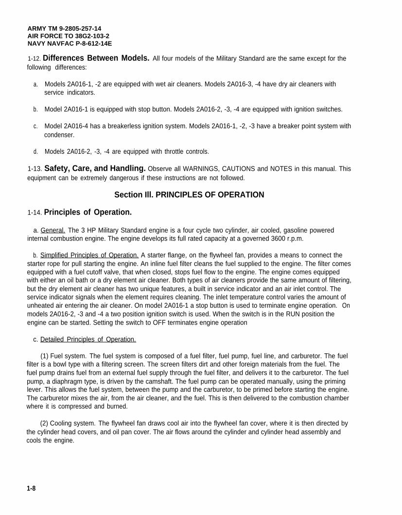
1-12. Differences Between Models. All four models of the Military Standard are the same except for thefollowing differences:
a.
b.
c.
d.
Models 2A016-1, -2 are equipped with wet air cleaners. Models 2A016-3, -4 have dry air cleaners withservice indicators.
Model 2A016-1 is equipped with stop button. Models 2A016-2, -3, -4 are equipped with ignition switches.
Model 2A016-4 has a breakerless ignition system. Models 2A016-1, -2, -3 have a breaker point system withcondenser.
Models 2A016-2, -3, -4 are equipped with throttle controls.
1-13. Safety, Care, and Handling. Observe all WARNINGS, CAUTIONS and NOTES in this manual. Thisequipment can be extremely dangerous if these instructions are not followed.
Section Ill. PRINCIPLES OF OPERATION
1-14. Principles of Operation.
a. General. The 3 HP Military Standard engine is a four cycle two cylinder, air cooled, gasoline poweredinternal combustion engine. The engine develops its full rated capacity at a governed 3600 r.p.m.
b. Simplified Principles of Operation. A starter flange, on the flywheel fan, provides a means to connect thestarter rope for pull starting the engine. An inline fuel filter cleans the fuel supplied to the engine. The filter comesequipped with a fuel cutoff valve, that when closed, stops fuel flow to the engine. The engine comes equippedwith either an oil bath or a dry element air cleaner. Both types of air cleaners provide the same amount of filtering,but the dry element air cleaner has two unique features, a built in service indicator and an air inlet control. Theservice indicator signals when the element requires cleaning. The inlet temperature control varies the amount ofunheated air entering the air cleaner. On model 2A016-1 a stop button is used to terminate engine operation.models 2A016-2, -3 and -4 a two position ignition switch is used. When the switch is in the RUN position theengine can be started. Setting the switch to OFF terminates engine operation
c. Detailed Principles of Operation.
On
(1) Fuel system. The fuel system is composed of a fuel filter, fuel pump, fuel line, and carburetor. The fuelfilter is a bowl type with a filtering screen. The screen filters dirt and other foreign materials from the fuel. Thefuel pump drains fuel from an external fuel supply through the fuel filter, and delivers it to the carburetor. The fuelpump, a diaphragm type, is driven by the camshaft. The fuel pump can be operated manually, using the priminglever. This allows the fuel system, between the pump and the carburetor, to be primed before starting the engine.The carburetor mixes the air, from the air cleaner, and the fuel. This is then delivered to the combustion chamberwhere it is compressed and burned.
(2) Cooling system. The flywheel fan draws cool air into the flywheel fan cover, where it is then directed bythe cylinder head covers, and oil pan cover. The air flows around the cylinder and cylinder head assembly andcools the engine.
1-8
ARMY TM 9-2805-257-14AIR FORCE TO 38G2-103-2
NAVY NAVFAC P-8-612-14E
(3) Air supply. The air cleaner, whether oil bath or dry element, cleans the air going to the carburetor. Theoil bath air cleaner uses oil to remove dirt from the air. The dry element air cleaner uses a dry fiber element toremove dirt from the air. As the element gets dirty, air flow through it decreases and creates a vacuum in the aircleaner. When air flow decreases too much, the service indicator shows a red signal and indicates the elementrequires cleaning.
(4) Speed regulation. All four models of the engine are equipped with a centrifugal flyweight governorconnected to the carburetor by a control rod. The governor determines the fastest speed at which the engine willrun. Model 2A016-1 has no speed regulation other than the adjustment of the governor. Model 2A016-2, -3 and-4 are equipped with throttle controls which overrides the function of the governor. The throttle control allows theengine speed to be adjusted between idle and full governed speed.
(5) Ignition system. There are two different types of ignition systems used on the engine. Model 2A016-1,-2, and -3, all use a breaker point ignition system. A set of breaker points triggers a condenser and coil to producea high voltage electric charge. This charge is then delivered, through a shielded ignition cable, to the spark pluglocated in the cylinder head. This charge creates a spark at the spark plug electrode, and ignites the air/fuelmixture in the combustion chamber. Model 2A016-4 uses a breakerless ignition system. This system useselectronic components to generate the high voltage electric charge to ignite the air/fuel mixture.
(6) Lubrication. Lubrication of the rocker and valve assemblies is accomplished by drawing oil vapors fromthe crankcase into the cylinder head assembly. A breather line connects the cylinder head with the air intakeelbow, mounted between the carburetor and air cleaner assembly. On Model 2A016-1, the breather line isconnected directly to the air cleaner assembly. The vacuum in the breather line is sufficient to draw oil vaporsfrom the crankcase, up through the push rod tubes, and into the cylinder head assembly.
1-9/(1-10 blank)

ARMY TM 9-2805-257-14AIR FORCE TO 38G2-103-2
NAVY NAVFAC P-8-612-14E
CHAPTER 2
OPERATING INSTRUCTIONS
Page
OVERVIEW . . . . . . . . . . . . . . . . . . . . . . . . . . . . . . . . . . . . . . . . . . . . . . . . . . . . . . . . . . . . . . . ...2-1Section l. Description and Use of Operator’s Controls and lndicators . . . . . . . . . . . . . . . . . . . . 2-1Section Il. Preventive Maintenance Checks and Services (PMCS) . . . . . . . . . . . . . . . . . . . . . . 2-4Section lll. Operation Under Usual Conditions . . . . . . . . . . . . . . . . . . . . . . . . . . . . . . . . . . . ...2-7Section IV. Operation Under Unusual Conditions . . . . . . . . . . . . . . . . . . . . . . . . . . . . . . . . . ...2-10
OVERVIEW
This chapter contains instructions and procedures required to operate the engine safely and efficiently.
Section I. DESCRIPTION AND USE OF OPERATORS’ CONTROLS AND INDICATORS
Paragraph Page
2-1 General . . . . . . . . . . . . . . . . . . . . . . . . . . . . . . . . . . . . . . . . . . . . . . . . . . . . . . . . . . . ...2-12-2 Operator’s Controls and Indicators . . . . . . . . . . . . . . . . . . . . . . . . . . . . . . . . . . . . . . ...2-1
2-1. General. This section contains a list of operator controls and indicators and a description of their use.
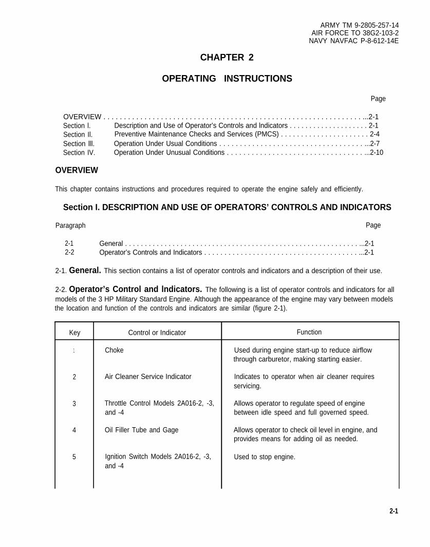
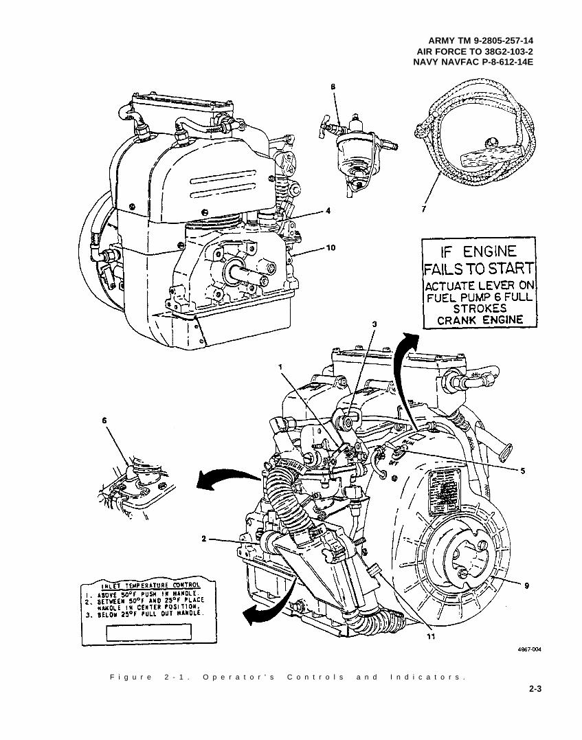
2-2. Operator’s Control and lndicators. The following is a list of operator controls and indicators for allmodels of the 3 HP Military Standard Engine. Although the appearance of the engine may vary between modelsthe location and function of the controls and indicators are similar (figure 2-1).
Key
1
2
3
4
5
Control or Indicator
Choke
Air Cleaner Service Indicator
Throttle Control Models 2A016-2, -3,and -4
Oil Filler Tube and Gage
Ignition Switch Models 2A016-2, -3,and -4
Function
Used during engine start-up to reduce airflowthrough carburetor, making starting easier.
Indicates to operator when air cleaner requiresservicing.
Allows operator to regulate speed of enginebetween idle speed and full governed speed.
Allows operator to check oil level in engine, andprovides means for adding oil as needed.
Used to stop engine.
2-1
ARMY TM 9-2805-257-14AIR FORCE TO 38G2-103-2NAVY NAVFAC P-8-612-14E
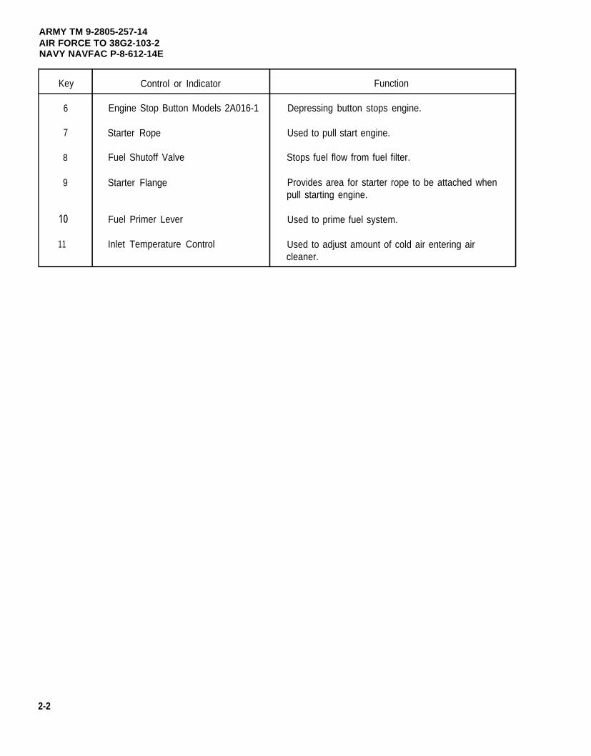
Key Control or Indicator Function
6 Engine Stop Button Models 2A016-1 Depressing button stops engine.
7 Starter Rope Used to pull start engine.
8 Fuel Shutoff Valve Stops fuel flow from fuel filter.
9 Starter Flange Provides area for starter rope to be attached whenpull starting engine.
10 Fuel Primer Lever Used to prime fuel system.
11 Inlet Temperature Control Used to adjust amount of cold air entering aircleaner.
2-2
ARMY TM 9-2805-257-14AIR FORCE TO 38G2-103-2
NAVY NAVFAC P-8-612-14E
F i g u r e 2 - 1 . O p e r a t o r ' s C o n t r o l s a n d I n d i c a t o r s .
2-3
ARMY TM 9-2805-257-14AIR FORCE TO 38G2-103-2NAVY NAVFAC P-8-612-14E
Section Il. PREVENTIVE MAINTENANCE CHECKS AND SERVICES (PMCS)
Paragraph Page
2-3 General . . . . . . . . . . . . . . . . . . . . . . . . . . . . . . . . . . . . . . . . . . . . . . . . . . . . . . . . . . . . ...2-42-4 Purpose of PMCS Table . . . . . . . . . . . . . . . . . . . . . . . . . . . . . . . . . . . . . . . . . . . . . . . ...2-42-5 Explanation of Columns . . . . . . . . . . . . . . . . . . . . . . . . . . . . . . . . . . . . . . . . . . . . . . . . ...2-42-6 Equipment is Not Ready/Available If Column . . . . . . . . . . . . . . . . . . . . . . . . . . . . . . . ...2-42-7 Reporting Deficiencies . . . . . . . . . . . . . . . . . . . . . . . . . . . . . . . . . . . . . . . . . . . . . . . . . ...2-52-8 Special Instructions . . . . . . . . . . . . . . . . . . . . . . . . . . . . . . . . . . . . . . . . . . . . . . . . . . . ...2-5
2-3. General. Operator PMCS are performed to ensure that the engine is ready for operation at all times.Perform the checks and services at the specified intervals.
a. Before you operate, perform your before (B) PMCS. Observe all CAUTIONS and WARNINGS.
b. While you operate, perform your during (D) PMCS. Observe all CAUTIONS and WARNINGS.
c. After you operate, be sure to perform your after (A) PMCS.
d. lf your equipment fails to operate, refer to paragraph 3-3.
2-4. Purpose of PMCS Table. The purpose of the PMCS table is to provide a systematic method ofinspection and servicing the equipment. In this way, small defects can be detected early before they become amajor problem causing the equipment to fail to complete its mission. The PMCS table is arranged with theindividual PMCS procedures listed in sequence under assigned intervals. The most logical time (before, during, orafter operation) to perform each procedure determines the interval to which it is assigned. Make a habit of doingthe checks in the same order each time and anything wrong will be seen quickly. See paragraphs 2-5 and 2-6 foran explanation of the columns in table 2-1.
2-5. Explanation Of Columns. The following is a list of the PMCS table column headings with a descriptionof the information found in each column.
a. Item No. This column shows the sequence in which the checks and services are to be performed, and isused to identify the equipment area on the Equipment Inspection and Maintenance Worksheet, DA Form 2404.
b. Interval. This column shows when each check is to be done.
c. Item to be lnspected/Procedures. This column identifies the general area or specific part where the checkor service is to be done, and explains how to do them.
d. Equipment is Not Ready/A vailable If. See paragraph 2-6.
2-6. Equipment is Not Ready/Available If Column. This column lists conditions that make theequipment unavailable for use because it is unable to perform its mission, or because it would represent a safetyhazard. Do not accept or operate equipment with a condition in the “Equipment is Not Ready/Available If” column.
2-4
ARMY TM 9-2805-257-14AIR FORCE TO 38G2-103-2
NAVY NAVFAC P-8-612-14E
NOTE
The terms ready/available and mission capable refer to the same status: Equipment is onhand and is able to perform its combat mission. Refer to DA Pam 738-750.
2-7. Reporting Deficiencies. If any problem with the equipment is discovered during PMCS or while it isbeing operated that cannot be corrected at the operator/crew maintenance level, it must be reported. Refer to DAPam 738-750 and report the deficiency using the proper forms.
2-8. Special Instructions. Preventive maintenance is not limited to performing the checks and serviceslisted in the PMCS table.
WARNING
Drycleaning solvent PD-680 used to clean parts is potentially dangerous to personnel andproperty. Avoid repeated and prolonged skin contact. Do not use near open flame orexcessive heat. Flash point of solvent is 100°F - 138°F (38°C - 60°C).
a. Keep it clean. Dirt, grease, oil, and debris get in the way and may cover up a serious problem. Clean asyou work and as needed. Use drycleaning solvent on all metal surfaces. Use soap and water to clean rubber orplastic material.
b. Bolts. Nuts. and Screws. Check them all for obvious looseness, missing, bent, or broken condition. Youcan’t try them all with a tool, but look for chipped paint, bare metal, or rust around boltheads. If you find one youthink is loose, tighten it, or report it to unit maintenance if you can’t tighten it.
c. Electrical Wires and Cable Connectors. Look for bare wires, and loose or broken connectors. Reportdefects to unit maintenance.
d. Fluid Lines. Look for wear, damage, and leaks. Make sure clamps and fittings are tight. Wet spots andstains around a fitting or connector can mean a leak. If a leak comes from a loose connector, tighten it. Ifsomething is broken or worn out, report it to unit maintenance.
e. Leakage Definitions. It is necessary for you to know how fluid leakage affects the status of your equipment.The following are definitions of the types/classes of leakage you need to know to be able to determine the statusof your equipment. Learn and be familiar with them. When in doubt, NOTIFY YOUR SUPERVISOR!
Leakage Definitions:
Class I Seepage of fluid (as indicated by wetness or discoloration) not greatenough to form drops.
Class II Leakage of fluid great enough to form drops but not enough to causedrops to drip from item being checked/inspected.
Class Ill Leakage of fluid great enough to form drops that fall from the item beingchecked/inspected.
2-5
ARMY TM 9-2805-257-14AIR FORCE TO 38G2-103-2NAVY NAVFAC P-8-612-14E
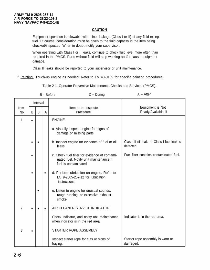
CAUTION
Equipment operation is allowable with minor leakage (Class I or II) of any fluid exceptfuel. Of course, consideration must be given to the fluid capacity in the item beingchecked/inspected. When in doubt, notify your supervisor.
When operating with Class I or II leaks, continue to check fluid level more often thanrequired in the PMCS. Parts without fluid will stop working and/or cause equipmentdamage.
Class Ill leaks should be reported to your supervisor or unit maintenance.
f. Painting. Touch-up engine as needed. Refer to TM 43-0139 for specific painting procedures.
Table 2-1. Operator Preventive Maintenance Checks and Services (PMCS).
B - Before D – During A – After
IntervalItem Item to be Inspected Equipment is Not
No. B D A Procedure Ready/Available If
1 ● ENGINE
a. Visually inspect engine for signs ofdamage or missing parts.
● ● b. Inspect engine for evidence of fuel or oil Class III oil leak, or Class I fuel leak isleaks. detected.
● c. Check fuel filter for evidence of contami- Fuel filter contains contaminated fuel.nated fuel. Notify unit maintenance iffuel is contaminated.
● ● d. Perform lubrication on engine. Refer toLO 9-2805-257-12 for lubricationinstructions.
● e. Listen to engine for unusual sounds,rough running, or excessive exhaustsmoke.
2 ● ● ● AIR CLEANER SERVICE INDICATOR
Check indicator, and notify unit maintenance Indicator is in the red area.when indicator is in the red area.
3 ● STARTER ROPE ASSEMBLY
Inspect starter rope for cuts or signs of Starter rope assembly is worn orfraying. damaged.
2-6
ARMY TM 9-2805-257-14AIR FORCE TO 38G2-103-2
NAVY NAVFAC P-8-612-14E
Section Ill. OPERATION UNDER USUAL CONDITIONS
Paragraph Page
2-9 Starting Procedure . . . . . . . . . . . . . . . . . . . . . . . . . . . . . . . . . . . . . . . . . . . . . . . . . . . . ...2-72-10 Stopping Procedures . . . . . . . . . . . . . . . . . . . . . . . . . . . . . . . . . . . . . . . . . . . . . . . . . . ...2-9
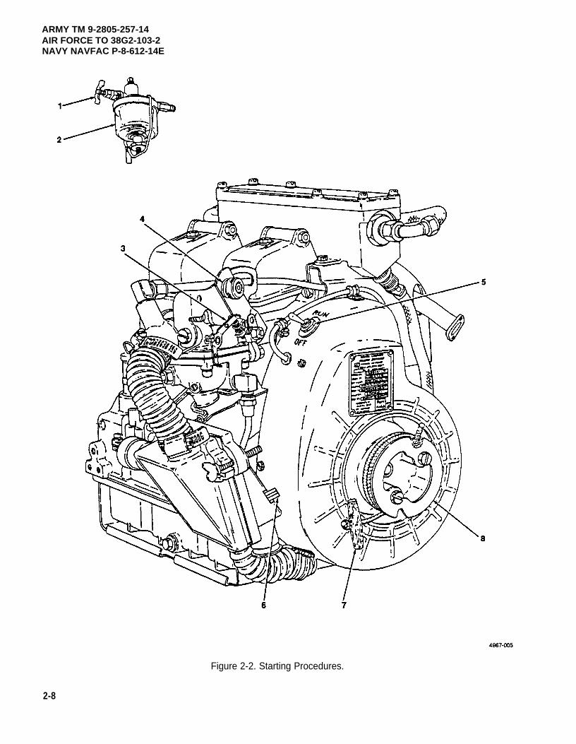
2-9. Starting Procedures. (figure 2-2)
a.
b.
c.
d.
e.
f.
g.
h.
i.
j.
Open fuel shutoff valve (1) on fuel filter (2).
Rotate choke control lever (3) counterclockwise and close choke.
On models 2A016 -2, 3, and -4, place throttle control (4) approximately 1/4 in. from idle position.
On models 2A016-2, 3, and -4, set ignition switch (5) to RUN position.
On models 2A016-3, -4, set inlet temperature control as follows:
(1) Above 50°F (10°C) push in handle (6).
(2) Between 50-25°F(10° (-4)°C), place handle (6) in center position.
(3) Below 25° (-4°C) pull out handle (6).
WARNING
Operation of the equipment presents a noise hazard to personnel in the area. The noiselevel exceeds the allowable limits for unprotected personnel. Wear ear muffs or ear plugswhich were fitted by a trained professional.
Serious eye injury can result from the starting rope knot. Wear eye protection when pullstarting engine.
Wind starter rope (7) clockwise around starter flange (8) and pull briskly.
When the engine has started, rotate the choke control lever (3) clockwise until the choke is fully opened,and the engine will continue to run.
NOTE
It maybe necessary on models 2A016-2, -3, and -4 to rotate the throttle controlcounterclockwise to obtain a smooth idle.
Allow engine to warm-up for at least 3 minutes.
On models 2A016-2,position.
Apply end item load.
-3, and -4, after warm-up, move throttle control counterclockwise to the full governed
Refer to End Item Operators Manual.
2-7
ARMY TM 9-2805-257-14AIR FORCE TO 38G2-103-2NAVY NAVFAC P-8-612-14E
Figure 2-2. Starting Procedures.
2-8
2-10
a.
b.
c.
d.
e.
f.
ARMY TM 9-2805-257-14AIR FORCE TO 38G2-103-2
NAVY NAVFAC P-8-612-14E
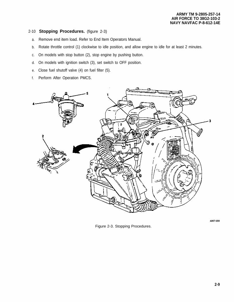
Stopping Procedures. (figure 2-3)
Remove end item load. Refer to End Item Operators Manual.
Rotate throttle control (1) clockwise to idle position, and allow engine to idle for at least 2 minutes.
On models with stop button (2), stop engine by pushing button.
On models with ignition switch (3), set switch to OFF position.
Close fuel shutoff valve (4) on fuel filter (5).
Perform After Operation PMCS.
Figure 2-3. Stopping Procedures.
2-9
ARMY TM 9-2805-257-14AIR FORCE TO 38G2-103-2NAVY NAVFAC P-8-612-14E
Section IV. OPERATION UNDER UNUSUAL CONDITIONS
Paragraph Page
2-11 Operation in Dusty or Sandy Areas... . . . . . . . . . . . . . . . . . . . . . . . . . . . . . . . . . . . . ...2-102-12 Operation in Rainy, Humid, or Salt Air Conditions . . . . . . . . . . . . . . . . . . . . . . . . . . . . . . . 2-102-13 Operation in Extreme Heat . . . . . . . . . . . . . . . . . . . . . . . . . . . . . . . . . . . . . . . . . . . . . ...2-102-14 Operation at Different Altitudes . . . . . . . . . . . . . . . . . . . . . . . . . . . . . . . . . . . . . . . . . . ...2-102-15 Operation in Extreme Cold . . . . . . . . . . . . . . . . . . . . . . . . . . . . . . . . . . . . . . . . . . . . . ...2-11
2-11. Operation in Dusty or Sandy Areas. The procedures for operating the engine are the same asunder usual conditions except for the following special precautions:
a.
b.
c.
d.
Keep fuel, lubrication, ignition and cooling systems free of dust and sand.
Inspect air cleaner assembly more often when operating in dusty or sandy areas. Have unit maintenanceservice air cleaner element as needed.
In the event of severe dust or sand storms, provide a well protected sheltering device for the engine.
Remove all dust or sand from the engine and inspect for damage.
2-12. Operation in Rainy, Humid, or Salt Air Conditions. The procedures for starting and stoppingthe engine are the same as under usual conditions except for the following special precautions:
a.
b.
c.
d.
2-13.
Remove all visible signs of corrosion as soon as possible.
Keep fuel lines, and ignition lines as dry as possible.
If possible, store engine indoors.
Use a thin layer of oil or desiccants to keep corrosion to a minimum.
Operation in Extreme Heat. The procedures for starting and stopping the engine are the same asunder normal condition except for the following special precautions:
a. Check oil level more often when operating in extreme heat.
b. Allow engine to cool off longer after removing end item load.
c. In extreme hot temperatures, the engine will run efficiently but at a reduced horse power rating. For each10°F (12.2°C) above 60°F(15.5°C) a 1 percent loss of power should be expected.
2-14. Operation at Different Altitudes. The procedures for starting and stopping the engine are thesame as under usual conditions. The engine will operate at altitudes of up to 5000 feet above sea level but at areduced horse power rating. For every 1000 feet above sea level, a 3.5 percent power loss should be expected.
2-10
ARMY TM 9-2805-257-14AIR FORCE TO 38G2-103-2
NAVY NAVFAC P-8-612-14E
2-15. Operation in Extreme Cold. The engine can be operated in temperatures a cold as -25°F (-32°C).The procedures for starting and stopping are the same as under usual conditions excepts for the following specialprecautions.
a. Protect the engine from icing. Remove ice and snow from engine as often as possible,
b. Allow engine sufficient warm-uptime before apply end item load.
2-11/(2-12 blank)

ARMY TM 9-2805-257-14AIR FORCE TO 38G2-103-2
NAVY NAVFAC P-8-612-14E
CHAPTER 3
OPERATOR’S MAINTENANCE INSTRUCTIONS
Page
OVERVIEW . . . . . . . . . . . . . . . . . . . . . . . . . . . . . . . . . . . . . . . . . . . . . . . . . . . . . . . . . . . . . . . ...3-1Section I. Lubrication Instructions . . . . . . . . . . . . . . . . . . . . . . . . . . . . . . . . . . . . . . . . . . . . ...3-1Section Il. Operator Troubleshooting Procedures . . . . . . . . . . . . . . . . . . . . . . . . . . . . . . . . . ...3-1
OVERVIEW
This chapter contains operator level maintenance instructions.
Section I. LUBRICATION INSTRUCTIONS
Paragraph Page
3-1 General . . . . . . . . . . . . . . . . . . . . . . . . . . . . . . . . . . . . . . . . . . . . . . . . . . . . . . . . . . . . ...3-13-2 Lubrication . . . . . . . . . . . . . . . . . . . . . . . . . . . . . . . . . . . . . . . . . . . . . . . . . . . . . . . . . . ...3-1
3-1. General. This section contains operator lubrication instructions.
3-2. Lubrication. Refer to L0 9-2805-257-12 and perform operator level lubrication procedures. Operate theengine (para. 2-9) for at least 5 minutes, after lubrication. Stop the engine (para. 2-10) and perform operator levelafter operation Preventive Maintenance Checks and Services (PMCS).
Air Force personnel use applicable T.O. 35C2-3-1-426 work cards for lubrication instructions.
Section Il. OPERATOR TROUBLESHOOTING
Paragraph Page
3-3 General . . . . . . . . . . . . . . . . . . . . . . . . . . . . . . . . . . . . . . . . . . . . . . . . . . . . . . . . . . . . ...3-13-4 Operator Troubleshooting Procedures.. . . . . . . . . . . . . . . . . . . . . . . . . . . . . . . . . . . . ...3-1
3-3. General. This section contains troubleshooting procedures to determine the probable cause of observedequipment malfunctions. Inspections are provided to isolate the faulty component and corrective actions areprovided to eliminate the malfunction.
3-4. Operator Troubleshooting Procedures. Refer to the Symptom Index to locate the troubleshootingprocedure for the observed malfunction.
a. Table 3-1 lists the common malfunctions which you may find during operation of 3 HP Military StandardGasoline Engine Models 2A016-1, -2, -3, and -4, and its components. Perform the test/inspections in theorder listed.
3-1
ARMY TM 9-2805-257-14AIR FORCE TO 38G2-103-2NAVY NAVFAC P-8-612-14E
b. This manual cannot list all malfunctions that may occur, nor all tests or inspections and corrective actions. Ifa malfunction is not corrected by listed corrective actions, notify your supervisor.
SYMPTOM INDEX
Symptom Page
Engine will not start . . . . . . . . . . . . . . . . . . . . . . . . . . . . . . . . . . . . . . . . . . . . . . . . . . . . . . . . . . . . . . . ...3-2Engine runs excessively hot . . . . . . . . . . . . . . . . . . . . . . . . . . . . . . . . . . . . . . . . . . . . . . . . . . . . . . . . ...3-2Engine starts but fails to keep running . . . . . . . . . . . . . . . . . . . . . . . . . . . . . . . . . . . . . . . . . . . . . . . . ...3-3
Table 3-1. Operator Troubleshooting Procedures.
MalfunctionTest or lnspection
Corrective Action
1. ENGINE WILL NOT START
Step 1. Check end item fuel supply.
Replenish fuel supply if low.
Step 2. Check fuel cutoff valve
Turn valve counterclockwise to open.
Step 3. Check choke position.
Choke should be in closed position for starting.
Step 4. Check ignition switch models 2A016-2, -3, -4.
Set ignition switch to RUN position.
2. ENGINE RUNS HOT
Step 1. Check oil level.
Replenish oil if low.
Step 2. Check that cooling system ducts, covers, and deflectors are present and serviceable.
Notify unit maintenance if there are damaged or missing items.
3-2
ARMY TM 9-2805-257-14AIR FORCE TO 38G2-103-2
NAVY NAVFAC P-8-612-14E
Table 3-1. Operator Troubleshooting Procedures (cont).
MalfunctionTest or Inspection
Corrective Action
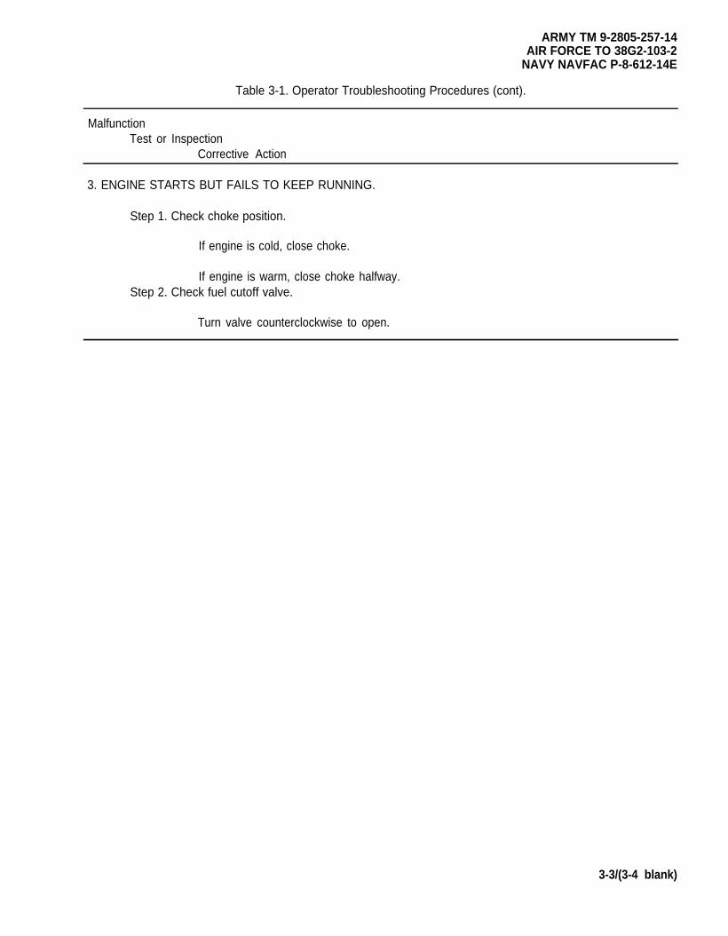
3. ENGINE STARTS BUT FAILS TO KEEP RUNNING.
Step 1. Check choke position.
If engine is cold, close choke.
If engine is warm, close choke halfway.Step 2. Check fuel cutoff valve.
Turn valve counterclockwise to open.
3-3/(3-4 blank)


ARMY TM 9-2805-257-14AIR FORCE TO 38G2-103-2
NAVY NAVFAC P-8-612-14E
CHAPTER 4
UNIT MAINTENANCE
Page
OVERVIEW . . . . . . . . . . . . . . . . . . . . . . . . . . . . . . . . . . . . . . . . . . . . . . . . . . . . . . . . . . . . . . . ...4-1Section l. Repair Parts; Special Tools; Test, Measurement, Diagnostic Equipment (TMDE);
and Support Equipment . . . . . . . . . . . . . . . . . . . . . . . . . . . . . . . . . . . . . . . . . . ...4-1Section Il. Service Upon Receipt . . . . . . . . . . . . . . . . . . . . . . . . . . . . . . . . . . . . . . . . . . . . . ...4-2Section Ill. Unit Preventive Maintenance Checks and Services (PMCS) . . . . . . . . . . . . . . . . . . . 4-2Section IV. Unit Troubleshooting . . . . . . . . . . . . . . . . . . . . . . . . . . . . . . . . . . . . . . . . . . . . . . ...4-3Section V. Unit Maintenance Procedures.. . . . . . . . . . . . . . . . . . . . . . . . . . . . . . . . . . . . . . ...4-7Section VI. Preparation for Shipment or Storage . . . . . . . . . . . . . . . . . . . . . . . . . . . . . . . . . . ...4-81
OVERVIEW
This chapter contains those maintenance instructions that unit Ievel maintenance is authorized to perform.
Section I. REPAIR PARTS; SPECIAL TOOLS; TEST, MEASUREMENT, DIAGNOSTICEQUIPMENT (TMDE); AND SUPPORT EQUIPMENT
Paragraph Page
4-1 Common Tools and Test Equipment . . . . . . . . . . . . . . . . . . . . . . . . . . . . . . . . . . . . . . ...4-14-2 Special Tools, TMDE, and Support Equipment . . . . . . . . . . . . . . . . . . . . . . . . . . . . . . ...4-14-3 Repair Parts . . . . . . . . . . . . . . . . . . . . . . . . . . . . . . . . . . . . . . . . . . . . . . . . . . . . . . . . . ...4-1
4-1. Common Tools and Equipment. For authorized common tools and equipment, refer to the ModifiedTable of Organization and Equipment (MTOE) applicable to your unit.
4-2. Special Tools, TMDE and Support Equipment. For a listing of special tools, TMDE, and supportequipment authorized for use on this equipment, refer to the Repair Parts and Special Tools List, TM 5-2805-257-24P, and the maintenance allocation chart (MAC), appendix B of this manual.
4-3. Repair Parts. Repair parts are listed and illustrated in the Repair Parts and Special Tools List for 3 HPMilitary Standard Engine TM 5-2805-257-24P.
4-1
ARMY TM 9-2805-257-14AIR FORCE TO 38G2-103-2NAVY NAVFAC P-8-612-14E
Section Il. SERVICE UPON RECEIPT
Paragraph Page
4-4 Inspection . . . . . . . . . . . . . . . . . . . . . . . . . . . . . . . . . . . . . . . . . . . . . . . . . . . . . . . . . . ...4-24-5 Lubrication . . . . . . . . . . . . . . . . . . . . . . . . . . . . . . . . . . . . . . . . . . . . . . . . . . . . . . . . . . ...4-24-6 Testing . . . . . . . . . . . . . . . . . . . . . . . . . . . . . . . . . . . . . . . . . . . . . . . . . . . . . . . . . . . . . ...4-2
4-4.
a.
b.
c.
4-5.
4-6.
Inspection.
Inspect the equipment for damage incurred during shipment. If the equipment has been damaged, reportthe damage on SF Form 364, Report of Discrepancy (ROD).
Check the equipment against the packing slip to see if the shipment incomplete. Report all discrepancies inaccordance with the instructions of DA PAM 738-750.
Check to see whether the equipment has been modified.
Lubrication. Refer to L0 9-2805-257-12 and perform unit level and operator level lubrication on engine.
Testing. Perform unit level PMCS, and operator Before (B) PMCS before starting engine. Start engine,para. 2-9, and run for at least 15 minutes. Observe the engine during operation. If any malfunctions arise,troubleshoot using table 4-2.
Section Ill. UNIT PREVENTIVE MAINTENANCE CHECKS AND SERVICES (PMCS)
Paragraph Page
4-7 General . . . . . . . . . . . . . . . . . . . . . . . . . . . . . . . . . . . . . . . . . . . . . . . . . . . . . . . . . . . . ...4-24-8 PMCS Procedures . . . . . . . . . . . . . . . . . . . . . . . . . . . . . . . . . . . . . . . . . . . . . . . . . . . . ...4-2
4-7. General. Unit level maintenance PMCS are done to ensure that the engine is in top operating condition.A comprehensive PMCS program reduces equipment downtime and increases the operational readiness of theengine.
4-8. PMCS Procedures. Unit level PMCS is contained in table 4-1. The numbers in the item No. columnshow the order in which the check or service should be done. These numbers should be used when recordingdeficiencies and shortcomings on DA Form 2404, Equipment Inspection and Maintenance Worksheet. The ● inthe Interval column indicates when a check or service should be done, as follows:
4-2
ItemNo.
1
2
3
4
5
6
7
Paragraph
ARMY TM 9-2805-257-14AIR FORCE TO 38G2–103-2
NAVY NAVFAC P-8-612–14E
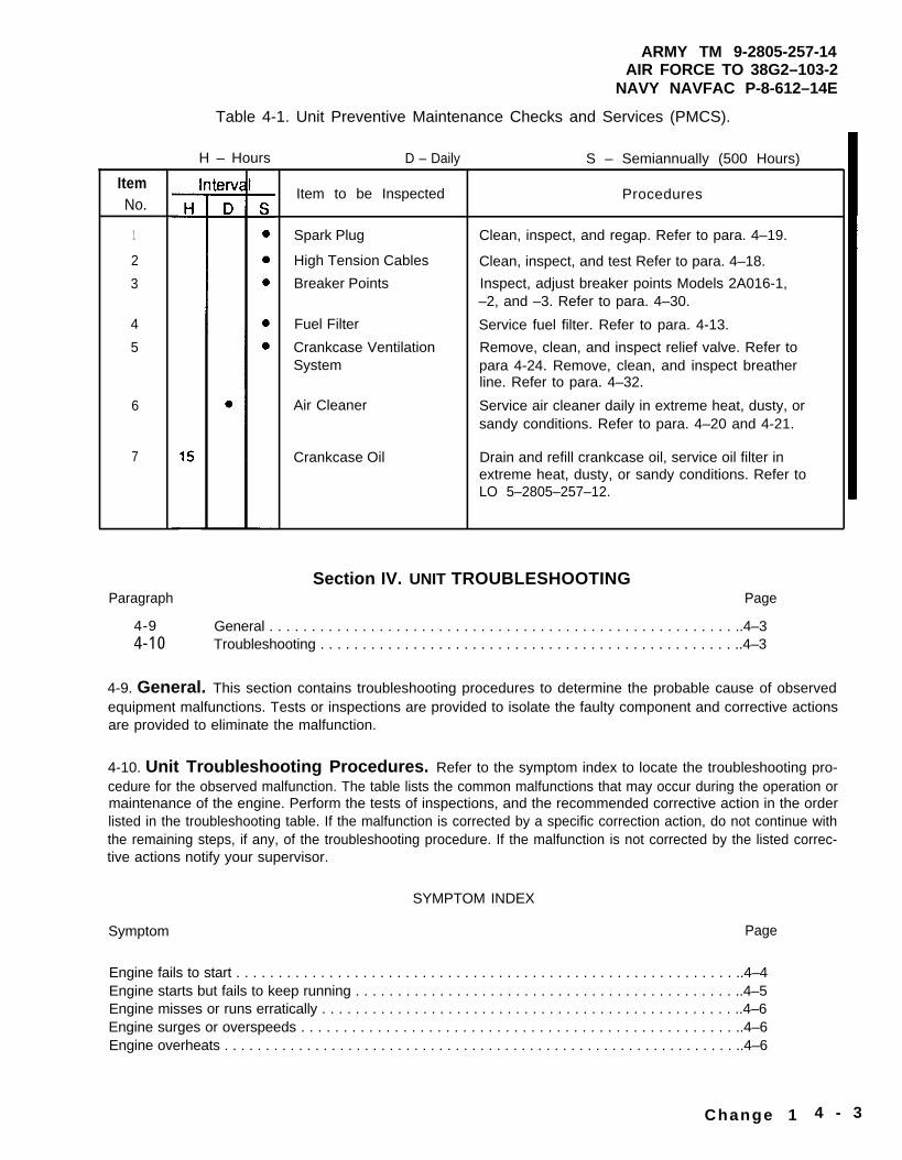
Table 4-1. Unit Preventive Maintenance Checks and Services (PMCS).
H – Hours D – Daily
Item to be Inspected
Spark Plug
High Tension Cables
Breaker Points
Fuel Filter
Crankcase VentilationSystem
Air Cleaner
Crankcase Oil
S – Semiannually (500 Hours)
Procedures
Clean, inspect, and regap. Refer to para. 4–19.
Clean, inspect, and test Refer to para. 4–18.
Inspect, adjust breaker points Models 2A016-1,–2, and –3. Refer to para. 4–30.
Service fuel filter. Refer to para. 4-13.
Remove, clean, and inspect relief valve. Refer topara 4-24. Remove, clean, and inspect breatherline. Refer to para. 4–32.
Service air cleaner daily in extreme heat, dusty, orsandy conditions. Refer to para. 4–20 and 4-21.
Drain and refill crankcase oil, service oil filter inextreme heat, dusty, or sandy conditions. Refer toLO 5–2805–257–12.
Section IV. UNIT TROUBLESHOOTINGPage
4-9 General . . . . . . . . . . . . . . . . . . . . . . . . . . . . . . . . . . . . . . . . . . . . . . . . . . . . . . . ..4–34-10 Troubleshooting . . . . . . . . . . . . . . . . . . . . . . . . . . . . . . . . . . . . . . . . . . . . . . . . . ..4–3
4-9. General. This section contains troubleshooting procedures to determine the probable cause of observedequipment malfunctions. Tests or inspections are provided to isolate the faulty component and corrective actionsare provided to eliminate the malfunction.
4-10. Unit Troubleshooting Procedures. Refer to the symptom index to locate the troubleshooting pro-cedure for the observed malfunction. The table lists the common malfunctions that may occur during the operation ormaintenance of the engine. Perform the tests of inspections, and the recommended corrective action in the orderlisted in the troubleshooting table. If the malfunction is corrected by a specific correction action, do not continue withthe remaining steps, if any, of the troubleshooting procedure. If the malfunction is not corrected by the listed correc-tive actions notify your supervisor.
SYMPTOM INDEX
Symptom Page
Engine fails to start . . . . . . . . . . . . . . . . . . . . . . . . . . . . . . . . . . . . . . . . . . . . . . . . . . . . . . . . . . . ..4–4Engine starts but fails to keep running . . . . . . . . . . . . . . . . . . . . . . . . . . . . . . . . . . . . . . . . . . . . . ..4–5Engine misses or runs erratically . . . . . . . . . . . . . . . . . . . . . . . . . . . . . . . . . . . . . . . . . . . . . . . . . ..4–6Engine surges or overspeeds . . . . . . . . . . . . . . . . . . . . . . . . . . . . . . . . . . . . . . . . . . . . . . . . . . . ..4–6Engine overheats . . . . . . . . . . . . . . . . . . . . . . . . . . . . . . . . . . . . . . . . . . . . . . . . . . . . . . . . . . . . . . ..4–6
Change 1 4 - 3
ARMY TM 9-2805-257-14AIR FORCE TO 38G2-103-2NAVY NAVFAC P-8-612-14E
Table 4-2. Unit Troubleshooting Procedures.
MALFUNCTIONTEST OR INSPECTION
CORRECTIVE ACTION
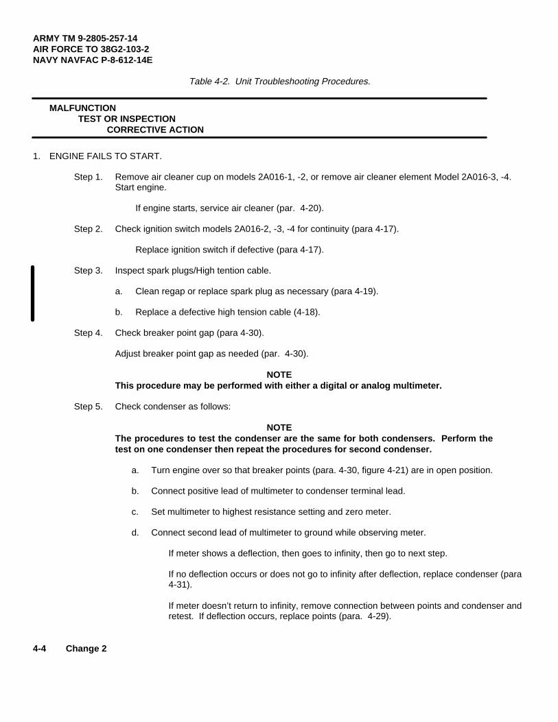
1. ENGINE FAILS TO START.
Step 1. Remove air cleaner cup on models 2A016-1, -2, or remove air cleaner element Model 2A016-3, -4.Start engine.
If engine starts, service air cleaner (par. 4-20).
Step 2. Check ignition switch models 2A016-2, -3, -4 for continuity (para 4-17).
Replace ignition switch if defective (para 4-17).
Step 3. Inspect spark plugs/High tention cable.
a. Clean regap or replace spark plug as necessary (para 4-19).
b. Replace a defective high tension cable (4-18).
Step 4. Check breaker point gap (para 4-30).
Adjust breaker point gap as needed (par. 4-30).
NOTEThis procedure may be performed with either a digital or analog multimeter.
Step 5. Check condenser as follows:
NOTEThe procedures to test the condenser are the same for both condensers. Perform thetest on one condenser then repeat the procedures for second condenser.
a. Turn engine over so that breaker points (para. 4-30, figure 4-21) are in open position.
b. Connect positive lead of multimeter to condenser terminal lead.
c. Set multimeter to highest resistance setting and zero meter.
d. Connect second lead of multimeter to ground while observing meter.
If meter shows a deflection, then goes to infinity, then go to next step.
If no deflection occurs or does not go to infinity after deflection, replace condenser (para4-31).
If meter doesn’t return to infinity, remove connection between points and condenser andretest. If deflection occurs, replace points (para. 4-29).
4-4 Change 2
ARMY TM 9-2805-257-14AIR FORCE TO 38G2-103-2
NAVY NAVFAC P-8-612-14E
Table 4-2. Unit Troubleshooting Procedures (cont).
Step 6. Check breaker points.
NOTE
The procedures to test breaker points are the same for both sets. Perform the test onone set then repeat procedure for second set.
a. Turn engine over so that breaker points (para. 4-30, figure 4-21) close.
b. Connect one lead of multimeter to condenser terminal.
c. Set multimeter to lowest resistance setting and zero meter.
d. Connect second lead of multimeter to ground while observing meter.
If meter shows full scale deflection, go to next step. If no deflection or partial deflectionoccurs, then replace breaker point (para. 4-29).
Step 7. Check fuel flow out of fuel filter.
Service fuel filter if fuel does not flow (para. 4-13).
Step 8. Check carburetor adjustments.
Adjust carburetor as needed (para. 4-34).
Step 9. Deleted.
2. ENGINE STARTS BUT FAILS TO KEEP RUNNING.
Step 1. Remove air cleaner cup on models 2A016-1, -2 or remove air cleaner element models 2A016-3, -4.Start Engine.
If engine stays running, service air cleaners (para. 4-20).
Step 2. Check fuel flow out of fuel filter assembly.
If fuel flow is not present or steady, service fuel filter assembly (para. 4-13).
Step 3. Check carburetor adjustments.
Adjust carburetor as needed (para. 4-34).
Change 2 4-5
ARMY TM 9-2805-257-14AIR FORCE TO 38G2-103-2NAVY NAVFAC P-8-612-14E
Table 4-2. Unit Troubleshooting Procedures (cont).
MalfunctionTest or Inspection
Corrective Action
Step 4. Check fuel pump pressure (para. 4-35).
Replace fuel pump if pressure is inadequate (para. 4-35).
3. ENGINE MISSES OR RUNS ERRATICALLY.
Step 1. Check spark plug.
Clean, regap, or replace worn spark plug (para. 4-19).
Step 2. Check breaker point gap.
Adjust or replace worn breaker points (para. 4-29).
Step 3. Check fuel flow out of fuel filter assembly.
If fuel flow is not present or steady, service fuel filter assembly (para. 4-13).
Step 4. Remove air cleaner cup on models 2A016-1, -2, or remove air cleaner element onmodels 2A016-3, -4 and start engine.
If engine runs properly, service air cleaner assembly (para. 4-20).
4. ENGINE SURGES OR OVERSPEED.
Step 1. Check Governor.
Adjust governor (para. 4-27).
Step 2. Check carburetor adjustments.
Adjust carburetor as needed (para 4-34).
5. ENGINE OVERHEATS.
Step 1. Check oil level.
Add oil as needed.
Step 2. Check cooling system.
Repair or replace a damaged or missing cooling system component (para. 4-14thru 4-16).
4-6
Paragraph
4-114-124-134-144-154-164-174-184-194-204-214-224-234-244-254-264-274-284-294-304-314-324-334-344-354-364-374-384-394-404-41
Section V. UNIT
General . . . . . . . . . . . . . . . . . . .
ARMY TM 9-2805-257-14AIR FORCE TO 38G2-103-2
NAVY NAVFAC P-8-612-14E
MAINTENANCE PROCEDURES
Page
. . . . . . . . . . . . . . . . . . . . . . . . . . . . . . . . . . . . . . . . . . . . 4-7
Painting . . . . . . . . . . . . . . . . . . . . . . . . . . . . . . . . . . . . . . . . . . . . . . . . . . . . . . . . . . . . ...4-7Fuel Filter Assembly . . . . . . . . . . . . . . . . . . . . . . . . . . . . . . . . . . . . . . . . . . . . . . . . . . . .4-8Flywheel Cover . . . . . . . . . . . . . . . . . . . . . . . . . . . . . . . . . . . . . . . . . . . . . . . . . . . . . . ...4-10Cylinder Head Covers . . . . . . . . . . . . . . . . . . . . . . . . . . . . . . . . . . . . . . . . . . . . . . . . . ...4-12Lower Air Duct and Upper Ai r Duct . . . . . . . . . . . . . . . . . . . . . . . . . . . . . . . . . . . . . . . ...4-16Ignition Switch . . . . . . . . . . . . . . . . . . . . . . . . . . . . . . . . . . . . . . . . . . . . . . . . . . . . . .4-18High Tension Cables . . . . . . . . . . . . . . . . . . . . . . . . . . . . . . . . . . . . . . . . . . . . . . . . . . ...4-20Spark Plugs . . . . . . . . . . . . . . . . . . . . . . . . . . . . . . . . . . . . . . . . . . . . . . . . . . . . . . . . . ...4-22Air Cleaner . . . . . . . . . . . . . . . . . . . . . . . . . . . . . . . . . . . . . . . . . . . . . . . . . . . . . . . . . . ...4-24Air Cleaner Assembly . . . . . . . . . . . . . . . . . . . . . . . . . . . . . . . . . . . . . . . . . . . . . . . . . ...4-28Clamps and Hoses . . . . . . . . . . . . . . . . . . . . . . . . . . . . . . . . . . . . . . . . . . . . . . . . . . . . ...4-32Air Cleaner Element . . . . . . . . . . . . . . . . . . . . . . . . . . . . . . . . . . . . . . . . . . . . . . . . . . . ...4-34Relief Valve . . . . . . . . . . . . . . . . . . . . . . . . . . . . . . . . . . . . . . . . . . . . . . . . . . . . . . . . . ...4-38Rocker Cover . . . . . . . . . . . . . . . . . . . . . . . . . . . . . . . . . . . . . . . . . . . . . . . . . . . . . . . . ...4-40Oil Fill Tube and Gage Assembly . . . . . . . . . . . . . . . . . . . . . . . . . . . . . . . . . . . . . . . . ...4-42Governor Assembly . . . . . . . . . . . . . . . . . . . . . . . . . . . . . . . . . . . . . . . . . . . . . . . . . . . ...4-44Breaker Points Cover (Breaker Point Ignition) . . . . . . . . . . . . . . . . . . . . . . . . . . . . . . . . . 4-46Breaker Points Assembly (Breaker Point Ignition) . . . . . . . . . . . . . . . . . . . . . . . . . . . . . . 4-48Breaker Points (Breaker Point Ignition) . . . . . . . . . . . . . . . . . . . . . . . . . . . . . . . . . . . ...4-50Condenser (Breaker Point Ignition) . . . . . . . . . . . . . . . . . . . . . . . . . . . . . . . . . . . . . . ...4-52Breather Line . . . . . . . . . . . . . . . . . . . . . . . . . . . . . . . . . . . . . . . . . . . . . . . . . . . . . . . . ...4-54Throttle Control . . . . . . . . . . . . . . . . . . . . . . . . . . . . . . . . . . . . . . . . . . . . . . . . . . . . . . ...4-58Carburetor . . . . . . . . . . . . . . . . . . . . . . . . . . . . . . . . . . . . . . . . . . . . . . . . . . . . . . . . . . ...4-60Fuel Pump . . . . . . . . . . . . . . . . . . . . . . . . . . . . . . . . . . . . . . . . . . . . . . . . . . . . . . . . . . . .4-66Fuel Line . . . . . . . . . . . . . . . . . . . . . . . . . . . . . . . . . . . . . . . . . . . . . . . . . . . . . . . . . . . ...4-70Starter Flange . . . . . . . . . . . . . . . . . . . . . . . . . . . . . . . . . . . . . . . . . . . . . . . . . . . . . . . ...4-72Flywheel . . . . . . . . . . . . . . . . . . . . . . . . . . . . . . . . . . . . . . . . . . . . . . . . . . . . . . . . . . . . ...4-74Intake Manifold . . . . . . . . . . . . . . . . . . . . . . . . . . . . . . . . . . . . . . . . . . . . . . . . . . . . . . . . . 4-76Exhaust Manifold . . . . . . . . . . . . . . . . . . . . . . . . . . . . . . . . . . . . . . . . . . . . . . . . . . . . . ...4-78Bearing Cap . . . . . . . . . . . . . . . . . . . . . . . . . . . . . . . . . . . . . . . . . . . . . . . . . . . . . . . . . ...4-80
4-11. General. This section contains unit level maintenance procedures as authorized by the MAC in AppendixB of this manual. Refer to Appendix E, Torque Limits, when performing maintenance on engine. All maintenanceprocedures require only one person to perform.
4-12. Painting. Refer to TM 43-0139 for painting procedures.
4-7
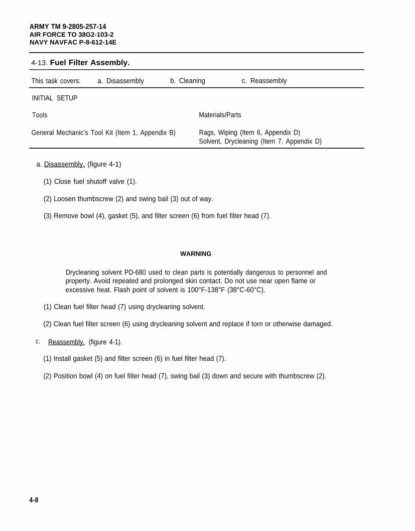
ARMY TM 9-2805-257-14AIR FORCE TO 38G2-103-2NAVY NAVFAC P-8-612-14E
4-13. Fuel Filter Assembly.
This task covers: a. Disassembly b. Cleaning c. Reassembly
INITIAL SETUP
Tools Materials/Parts
General Mechanic’s Tool Kit (Item 1, Appendix B) Rags, Wiping (Item 6, Appendix D)Solvent, Drycleaning (Item 7, Appendix D)
a. Disassembly. (figure 4-1)
(1) Close fuel shutoff valve (1).
(2) Loosen thumbscrew (2) and swing bail (3) out of way.
(3) Remove bowl (4), gasket (5), and filter screen (6) from fuel filter head (7).
WARNING
Drycleaning solvent PD-680 used to clean parts is potentially dangerous to personnel andproperty. Avoid repeated and prolonged skin contact. Do not use near open flame orexcessive heat. Flash point of solvent is 100°F-138°F (38°C-60°C).
(1) Clean fuel filter head (7) using drycleaning solvent.
(2) Clean fuel filter screen (6) using drycleaning solvent and replace if torn or otherwise damaged.
c. Reassembly. (figure 4-1).
(1) Install gasket (5) and filter screen (6) in fuel filter head (7).
4-8
(2) Position bowl (4) on fuel filter head (7), swing bail (3) down and secure with thumbscrew (2).
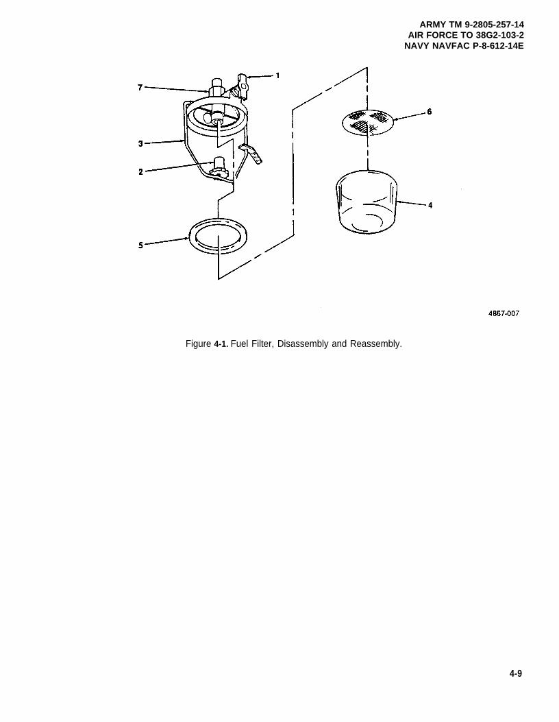
ARMY TM 9-2805-257-14AIR FORCE TO 38G2-103-2
NAVY NAVFAC P-8-612-14E
Figure 4-1. Fuel Filter, Disassembly and Reassembly.
4-9
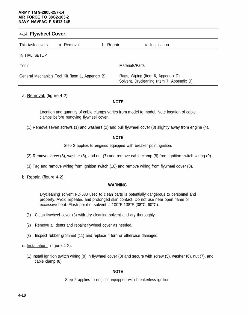
ARMY TM 9-2805-257-14AIR FORCE TO 38G2-103-2NAVY NAVFAC P-8-612-14E
4-14. Flywheel Cover.
This task covers: a. Removal b. Repair c. Installation
INITIAL SETUP
Tools Materials/Parts
General Mechanic’s Tool Kit (Item 1, Appendix B) Rags, Wiping (Item 6, Appendix D)Solvent, Drycleaning (Item 7, Appendix D)
a. Removal. (figure 4-2)
NOTE
Location and quantity of cable clamps varies from model to model. Note location of cableclamps before removing flywheel cover.
(1) Remove seven screws (1) and washers (2) and pull flywheel cover (3) slightly away from engine (4).
NOTE
Step 2 applies to engines equipped with breaker point ignition.
(2) Remove screw (5), washer (6), and nut (7) and remove cable clamp (8) from ignition switch wiring (9).
(3) Tag and remove wiring from ignition switch (10) and remove wiring from flywheel cover (3).
b. Repair. (figure 4-2)
(1)
(2)
(3)
WARNING
Drycleaning solvent PD-680 used to clean parts is potentially dangerous to personnel andproperty. Avoid repeated and prolonged skin contact. Do not use near open flame orexcessive heat. Flash point of solvent is 100°F-138°F (38°C–60°C).
Clean flywheel cover (3) with dry cleaning solvent and dry thoroughly.
Remove all dents and repaint flywheel cover as needed.
Inspect rubber grommet (11) and replace if torn or otherwise damaged.
c. Installation. (figure 4-2).
(1) Install ignition switch wiring (9) in flywheel cover (3) and secure with screw (5), washer (6), nut (7), andcable clamp (8).
NOTE
Step 2 applies to engines equipped with breakerless ignition.
4-10
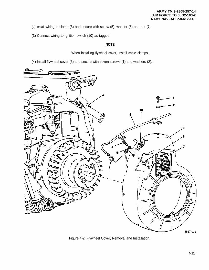
ARMY TM 9-2805-257-14AIR FORCE TO 38G2-103-2
NAVY NAVFAC P-8-612-14E
(2) Install wiring in clamp (8) and secure with screw (5), washer (6) and nut (7).
(3) Connect wiring to ignition switch (10) as tagged.
NOTE
When installing flywheel cover, install cable clamps.
(4) Install flywheel cover (3) and secure with seven screws (1) and washers (2).
Figure 4-2. Flywheel Cover, Removal and Installation.
4-11
ARMY TM 9-2805-257-14AIR FORCE TO 38G2-103-2NAVY NAVFAC P-8-612-14E
4-15. Cylinder Head Covers.
This task covers: a. Removal b. Repair c. Installation
INITIAL SETUP
Tools Equipment Condition
General Mechanic’s Tool Kit (Item 1, Appendix B) Flywheel cover removed (para. 4-14).
Materials/Parts
Rags, Wiping (Item 6, Appendix D)Solvent, Drycleaning (Item 7, Appendix D)
a. Removal. (figure 4-3)
(1)
(2)
(3)
(4)
(5)
NOTE
Step 1 applies to engines equipped with breakerless ignition.
Remove two screws (1) and washers (2) and move ignition control unit (3) out of way.
Remove three (only one on engines with breakerless ignition) screws (4) and washers (5) and removecenter cylinder head cover (6) and manifold cover (7).
Remove two (only one on engines with breakerless ignition) screws (8) and washers (9) and removeflywheel side cylinder head cover (10).
Remove three screws (11)and washers (12) and remove crankshaft side cylinder head cover (13).
NOTE
It may be necessary to remove oil level gage to gain access to mounting hardware for thecylinder head cover.
Remove two screws (14) and washers (15) and remove cylinder head cover (16).
b. Repair.
(1)
(2)
4-12
WARNING
Drycleaning solvent PD-680 used to clean parts is potentially dangerous to personnel andproperty. Avoid repeated and prolonged skin contact. Do not use near open flame orexcessive heat. Flash point of solvent is 100°F-138°F (38°C-60°C).
Clean all parts in dry cleaning solvent and dry thoroughly.
Repair all dents in cylinder head covers and repaint as necessary.
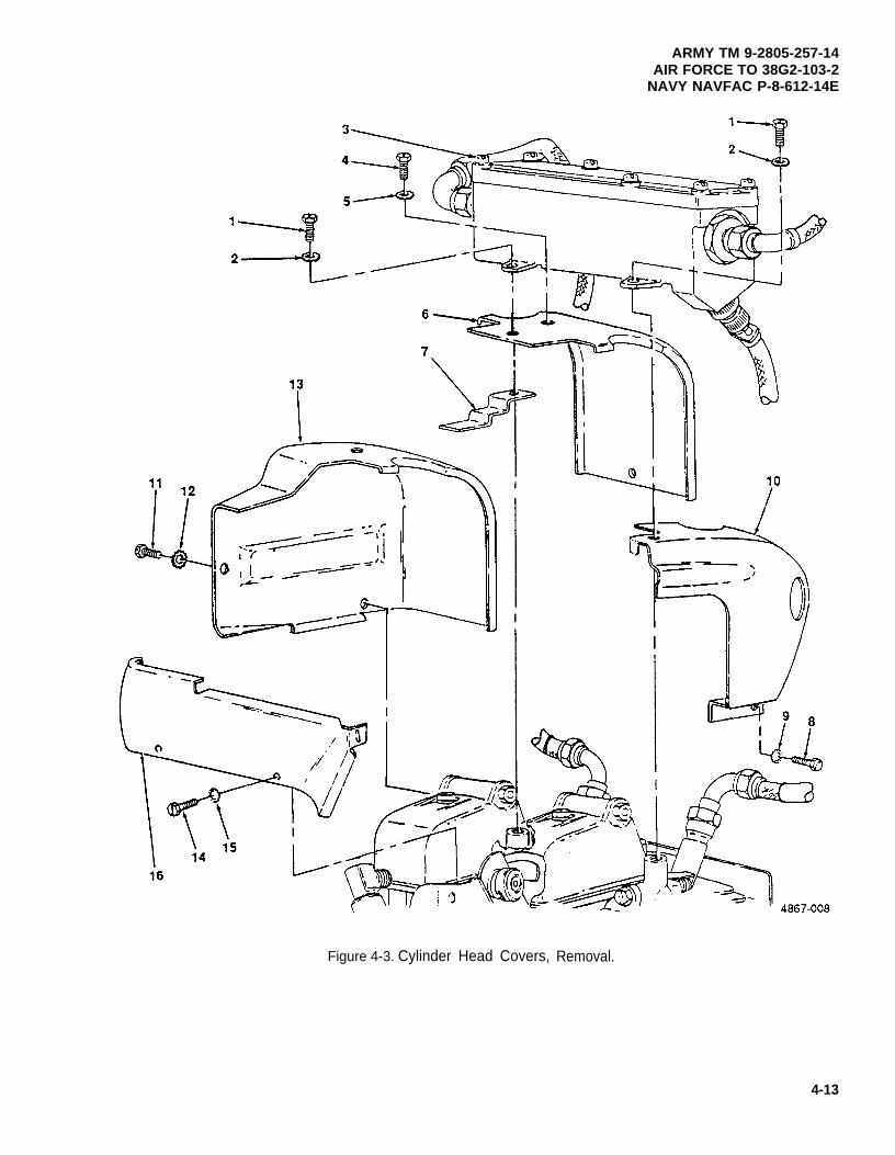
ARMY TM 9-2805-257-14AIR FORCE TO 38G2-103-2
NAVY NAVFAC P-8-612-14E
Figure 4-3. Cylinder Head Covers, Removal.
4-13
ARMY TM 9-2805-257-14AIR FORCE TO 38G2-103-2NAVY NAVFAC P-8-612-14E
4-15. Cylinder Head Covers (cont).
c. Installation . (figure 4-4)
(1) Install cylinder head cover (16) and secure with two screws (14) and washers (15).
(2) Install crankshaft side cylinder head cover (13) and secure with screw (11) and washer (12).
(3) Install flywheel side cylinder head cover (10) and secure with screw (8) and washer (9).
(4) install center cylinder head cover (6) and manifold cover (7) and secure (only on engines equipped withbreaker point ignition) with screw (4) and washer (5).
NOTE
Step 5 applies to engines equipped with breakerless ignition
(5) Install ignition control unit (3) and secure with two screws (1) and washers (2).
4-14
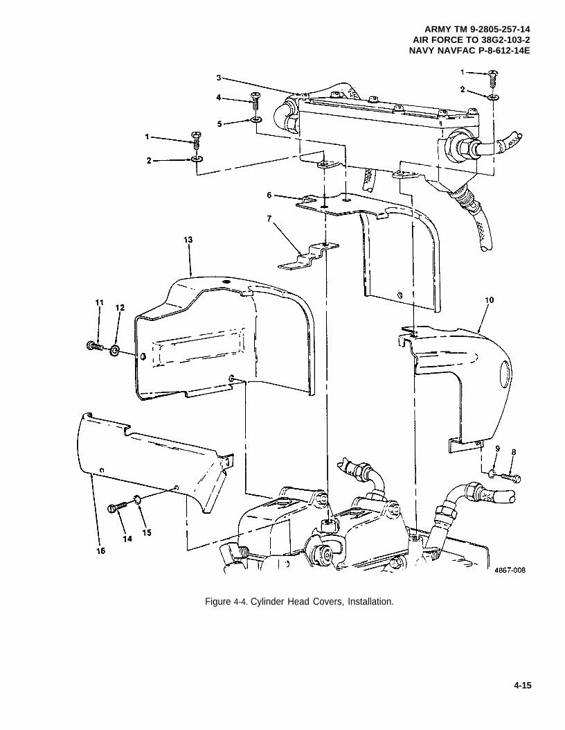
ARMY TM 9-2805-257-14AIR FORCE TO 38G2-103-2
NAVY NAVFAC P-8-612-14E
Figure 4-4. Cylinder Head Covers, Installation.
4-15
ARMY TM 9-2805-257-14AIR FORCE TO 38G2-103-2NAVY NAVFAC P-8-612-14E
4-16. Lower Air Duct and Upper Air Duct.
This task covers: a. Removal b. Repair c. Installation
INITIAL SETUP
Tools Materials/Parts
General Mechanic’s Tool Kit (Item 1, Appendix B) Rags, Wiping (Item 6, Appendix D)Solvent, Drycleaning (Item 7, Appendix D)
a. Removal. (figure 4-5)
(1) Remove four screws (1) and washers (2) securing lower air duct (3) to oil pan (4).
(2) Remove screw (5), washer (6) and nut (7) and remove lower air duct (3).
(3) Remove three screws (8) and washers (9) and remove upper air duct (10).
b. Repair. (figure 4-5)
WARNING
Drycleaning solvent PD-680 used to clean parts is potentially dangerous to personnel andproperty. Avoid repeated and prolonged skin contact. Do not use near open flame orexcessive heat. Flash point of solvent is 100°F–138°F (38°C–60°C).
(1) Clean lower air duct (3) and upper air duct (10) with dry cleaning solvent and dry thoroughly.
(2) Repair all dents and repaint as necessary.
c. Installation. (figure 4-5)
(1)
(2)
(3)
4-16
Install upper air duct (10) and secure with three screws (8) and washers (9).
Install lower air duct (3) and secure with screw (5), washer (6) and nut (7).
Secure lower air duct (3) to oil pan (4) using four screws (1) and washers (2).
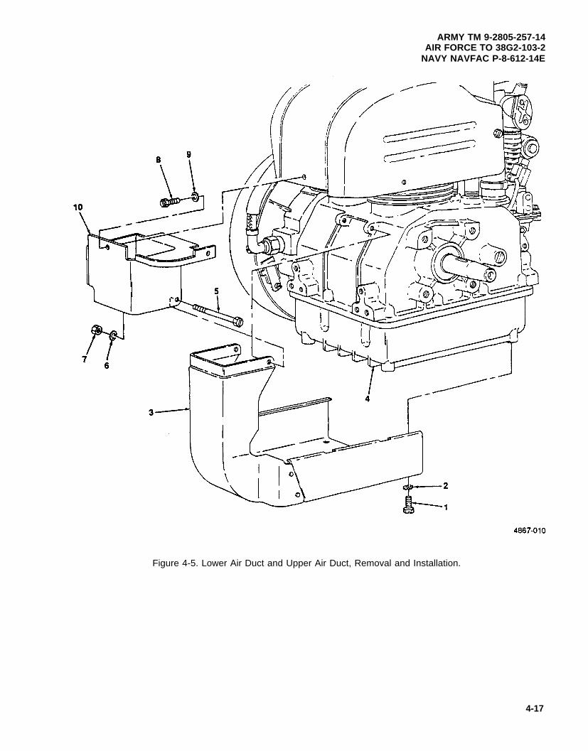
ARMY TM 9-2805-257-14AIR FORCE TO 38G2-103-2
NAVY NAVFAC P-8-612-14E
Figure 4-5. Lower Air Duct and Upper Air Duct, Removal and Installation.
4-17
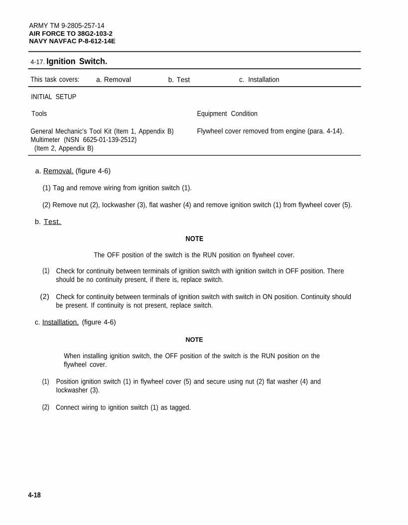
ARMY TM 9-2805-257-14AIR FORCE TO 38G2-103-2NAVY NAVFAC P-8-612-14E
4-17. Ignition Switch.
This task covers: a. Removal b. Test c. Installation
INITIAL SETUP
Tools Equipment Condition
General Mechanic’s Tool Kit (Item 1, Appendix B) Flywheel cover removed from engine (para. 4-14).Multimeter (NSN 6625-01-139-2512)
(Item 2, Appendix B)
a. Removal. (figure 4-6)
(1) Tag and remove wiring from ignition switch (1).
(2) Remove nut (2), Iockwasher (3), flat washer (4) and remove ignition switch (1) from flywheel cover (5).
b. Test.
(1)
(2)
NOTE
The OFF position of the switch is the RUN position on flywheel cover.
Check for continuity between terminals of ignition switch with ignition switch in OFF position. Thereshould be no continuity present, if there is, replace switch.
Check for continuity between terminals of ignition switch with switch in ON position. Continuity shouldbe present. If continuity is not present, replace switch.
c. Installlation. (figure 4-6)
(1)
(2)
NOTE
When installing ignition switch, the OFF position of the switch is the RUN position on theflywheel cover.
Position ignition switch (1) in flywheel cover (5) and secure using nut (2) flat washer (4) andIockwasher (3).
Connect wiring to ignition switch (1) as tagged.
4-18
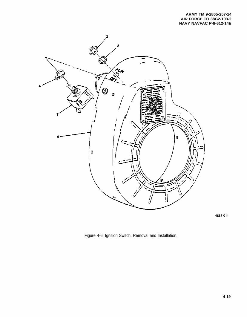
ARMY TM 9-2805-257-14AIR FORCE TO 38G2-103-2
NAVY NAVFAC P-8-612-14E
4-19
Figure 4-6. Ignition Switch, Removal and Installation.
ARMY TM 9-2805-257-14AIR FORCE TO 38G2-103-2NAVY NAVFAC P-8-612-14E
4-18. High Tension Cables.
This task covers: a. Removal b. Test/Inspection c. Installation
INITIAL SETUP
Tools Equipment Condition
GeneraI Mechanic’s Tool Kit (Item 1, Appendix B) Flywheel cover removed when replacing flywheel sideMultimeter (NSN 6625-01 -139-2512) ignition cable on engines equipped with breaker point
(Item 2, Appendix B) ignition (para. 4-14).
a. Removal. (figure 4-6)
NOTE
If removing high tension cables on engines with breakerless ignition system, perform step3 only. The high tension cables are located between ignition control unit and spark plugs.
Perform step 1 only if flywheel cover is still installed.
(1) Remove screw (1) and washer (2) and remove cable clamp (3) securing high tension cables (4).
NOTE
Perform step 2 only if flywheel side high tension cable is being removed.
(2) Remove two screws (5) and washers (6) and remove high tension cable access plate (7).
(3) Loosen cable nuts (8) and remove high tension cable (4).
b. Test/Inspection.
(1) Perform continuity test between spring ends of cable. Replace cable if no continuity is found.
(2) Perform continuity test between metal cable ends of cable. Replace cable if continuity is not found.
(3) Perform continuity test between spring end and metal cable end. Replace cable if continuity is found.
(4) Replace cable if damaged.
c. Installation. (figure 4-7)
(1) Install high tension cables (4) and tighten cable nuts (8).
(2) Install high tension cable access plate (7) and secure with two screws (5) and washers (6).
(3) Install cable clamp (3) on high tension cables (4) and secure with screw (1) and washer (2).
4-20
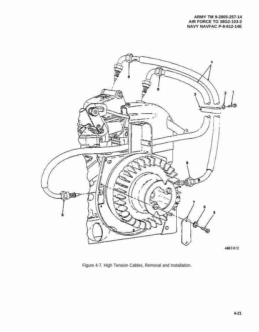
ARMY TM 9-2805-257-14AIR FORCE TO 38G2-103-2
NAVY NAVFAC P-8-612-14E
Figure 4-7. High Tension Cables, Removal and Installation.
4-21
ARMY TM 9-2805-257-14AIR FORCE TO 38G2-103-2NAVY NAVFAC P-8-612-14E
4-19. Spark Plugs.
This task covers: a. Removal b. Inspection/Test c. Installation
INITIAL SETUP
Tools Materials/Parts
General Mechanic’s Tool Kit (Item 1, Appendix B) Rags, Wiping (Item 6, Appendix D)Wrench, Torque (NSN 5120-00-640-6364) Solvent, Drycleaning (Item 7, Appendix D)
(Item 2, Appendix B)
NOTE
This engine has two spark plugs. Perform all procedures on one plug then the other.
a. Removal. (figure 4-8)
(1) Loosen connector nut (1) on high tension cable (2) and remove cable from spark plug (3).
(2) Remove spark plug (3) and washer (4).
b. Inspection/Test.
(1)
(2)
WARNING
Drycleaning solvent PD-680 used to clean parts is potentially dangerous to personnel andproperty. Avoid repeated and prolonged skin contact. Do not use near open flame orexcessive heat. Flash point of solvent is 100°F–138°F (38°C-60°C).
Clean spark plug using drycleaning solvent, and inspect plug for burning, cracked or broken ceramicinsulation, and damaged thread. Replace plug if damaged.
Regap spark plug to .028 to .033 in. (.071 to .083 cm).
c. Installation. (figure 4-8)
(1) Install spark plug (3) and washer (4) and torque to 275-300 in.-lbs (49115-53580 gr cm).
(2) Install high tension cable (2) on spark plug (3) and tighten connector nut (1).
4-22
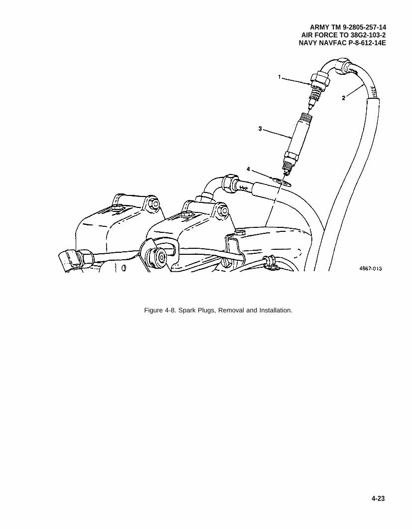
ARMY TM 9-2805-257-14AIR FORCE TO 38G2-103-2
NAVY NAVFAC P-8-612-14E
Figure 4-8. Spark Plugs, Removal and Installation.
4-23
ARMY TM 9-2805-257-14AIR FORCE TO 38G2-103-2NAVY NAVFAC P-8-612-14E
4-20. Air Cleaner.
This task covers: a. Service (oil bath) b. Service (dry)
INITIAL SETUP
Tools Materials/Parts
General Mechanic’s Tool Kit (Item 1, Appendix B) Rags, Wiping (Item 6, Appendix D)Solvent, Drycleaning (Item 7, Appendix D)Oil, OE/HDO 15W-40 (Item 2, Appendix D)
a. Service. Oil Bath. (figure 4-9)
(1) Unsnap two retaining clips (1) and remove lower cup (2) of air cleaner assembly.
(2) Pour oil into suitable container and remove element (3).
WARNING
Drycleaning solvent PD-680 used to clean parts is potentially dangerous to personnel andproperty. Avoid repeated and prolonged skin contact. Do not use near open flame orexcessive heat. Flash point of solvent is 100°F-138°F (38°C–60°C).
(3) Clean both halves of the air cleaner assembly and the element in drycleaning solvent.
(4) Dry everything thoroughly.
(5) Install element (3) in lower cup (2), and fill with oil to LEVEL line.
(6) Install lower cup (2) and secure with two retaining clips (1).
4-24
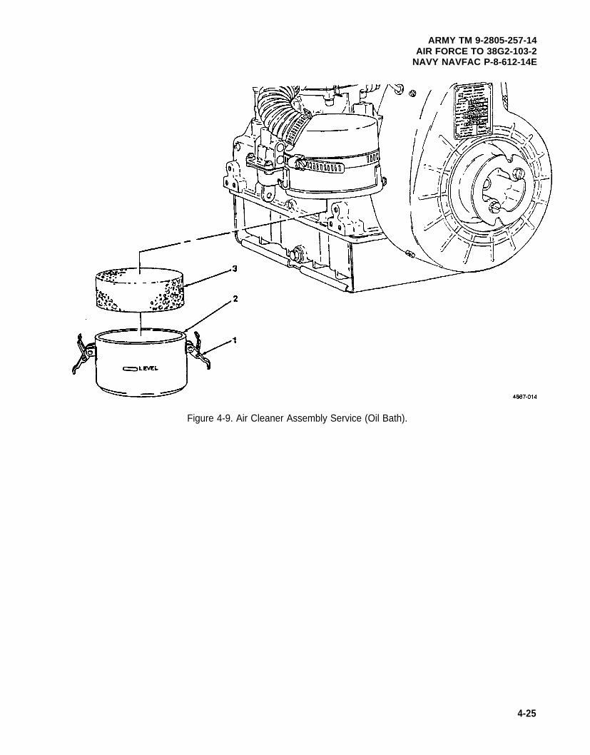
ARMY TM 9-2805-257-14AIR FORCE TO 38G2-103-2
NAVY NAVFAC P-8-612-14E
Figure 4-9. Air Cleaner Assembly Service (Oil Bath).
4-25
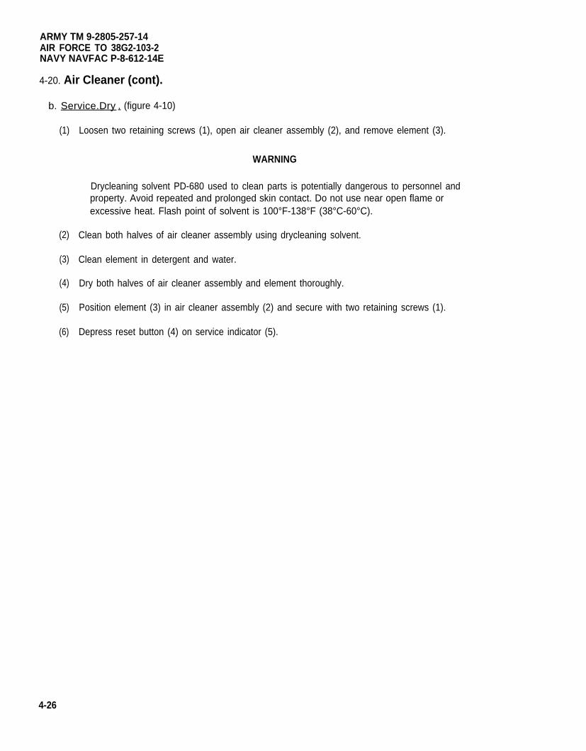
ARMY TM 9-2805-257-14AIR FORCE TO 38G2-103-2NAVY NAVFAC P-8-612-14E
4-20. Air Cleaner (cont).
b. Service.Dry . (figure 4-10)
(1)
(2)
(3)
(4)
(5)
(6)
4-26
Loosen two retaining screws (1), open air cleaner assembly (2), and remove element (3).
WARNING
Drycleaning solvent PD-680 used to clean parts is potentially dangerous to personnel andproperty. Avoid repeated and prolonged skin contact. Do not use near open flame orexcessive heat. Flash point of solvent is 100°F-138°F (38°C-60°C).
Clean both halves of air cleaner assembly using drycleaning solvent.
Clean element in detergent and water.
Dry both halves of air cleaner assembly and element thoroughly.
Position element (3) in air cleaner assembly (2) and secure with two retaining screws (1).
Depress reset button (4) on service indicator (5).
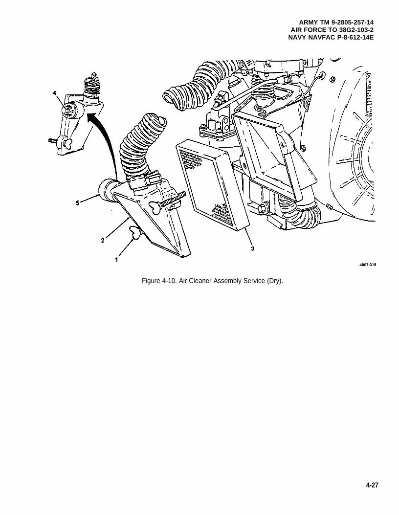
ARMY TM 9-2805-257-14AIR FORCE TO 38G2-103-2
NAVY NAVFAC P-8-612-14E
Figure 4-10. Air Cleaner Assembly Service (Dry).
4-27
ARMY TM 9-2805-257-14AIR FORCE TO 38G2-103-2NAVY NAVFAC P-8-612-14E
4-21. Air Cleaner Assembly.
This task covers: a. Removal (dry) c. Removal (oil bath)b. Installation (dry) d. Installation (oil bath)
INITIAL SETUP
Tools Equipment Condition
General Mechanic’s Tool Kit (Item 1, Appendix B) Flywheel cover removed for removal of dry air cleaner(para. 4-14).
a. Removal. Dry. (figure 4-11)
(1)
(2)
(3)
Loosen clamp (1) and remove air cleaner duct (2) from intake elbow (3).
Remove two screws (4) and washers (5) securing air cleaner assembly (6) and remove.
Inspect service indicator (7) and replace if cracked or otherwise damaged.
b. Installation. Dry. (figure 4-11)
(1) Position air cleaner assembly (6) on engine and secure with two screws (4) and washers (5).
(2) Install air cleaner duct (2) on intake elbow (3) and tighten clamp (1).
4-28
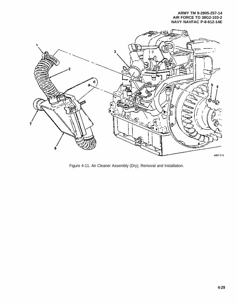
ARMY TM 9-2805-257-14AIR FORCE TO 38G2-103-2
NAVY NAVFAC P-8-612-14E
Figure 4-11. Air Cleaner Assembly (Dry), Removal and Installation.
4-29
ARMY TM 9-2805-257-14AIR FORCE TO 38G2-103-2NAVY NAVFAC P-8-612-14E
4-21. Air Cleaner Assembly (cont).
c. Removal. Oil Bath. (figure 4-12)
(1) Disconnect breather line (1) from air cleaner assembly (2).
(2) Loosen clamp (3) and remove air cleaner duct (4) from intake elbow (5).
(3) Loosen mounting clamp (6) and remove air cleaner assembly (2).
d. Installation. Oil Bath. (figure 4-12)
(1) Position air cleaner assembly (2) on engine and secure with mounting clamp (6).
(2) Install air cleaner duct (4) on intake elbow (5) and tighten clamp (3).
(3) Connect breather line (1) to air cleaner assembly (2).
4-30
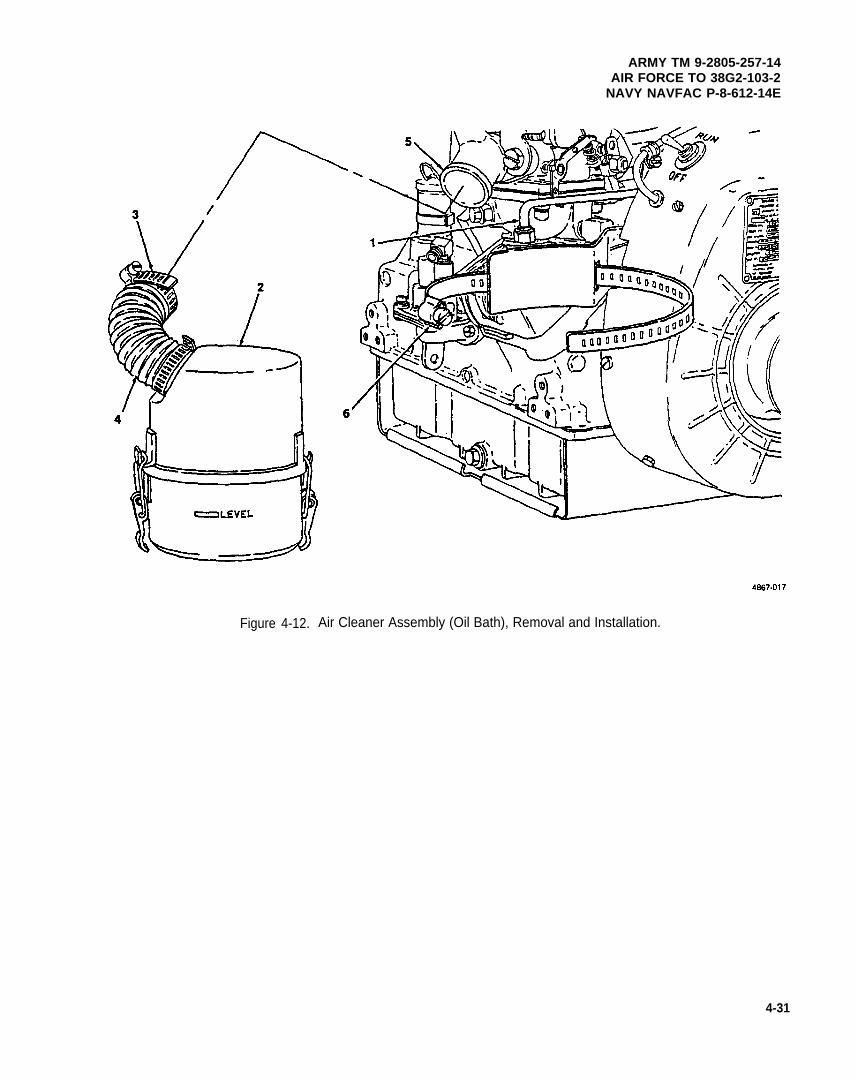
ARMY TM 9-2805-257-14AIR FORCE TO 38G2-103-2
NAVY NAVFAC P-8-612-14E
Figure 4-12. Air Cleaner Assembly (Oil Bath), Removal and Installation.
4-31
ARMY TM 9-2805-257-14AIR FORCE TO 38G2-103-2NAVY NAVFAC P-8-612-14E
4-22. Clamps and Hoses.
This task covers: Replacement
INITIAL SETUP
Tools
General Mechanic’s Tool Kit (Item 1, Appendix B)
a. Relacement. (figure 4-13)
NOTE
The procedures for replacing the hoses and clamps are the same for either dry elementor oil bath air cleaners.
(1) Loosen clamp (1) and remove hose (2) from air intake elbow (3).
(2) Loosen clamp (4) and remove hose (2) from air cleaner (5).
(3) Loosen clamp (6) and remove hose (7) from air cleaner (5).
(4) Remove screw (8) and washer (9) and remove hose loop clamp (10) and hose (7).
(5) Inspect hoses and clamps for damage and replace as needed.
(6) Install hose loop clamp (10) and hose (7) and secure with screw (8) and washer (9).
(7) Install hose (7) on air cleaner (5) and secure with clamp (6).
(8) Install hose (2) on air cleaner (5) and secure with clamp (4).
(9) Install hose (2) on air intake elbow (3) and secure with clamp (1).
4 - 3 2
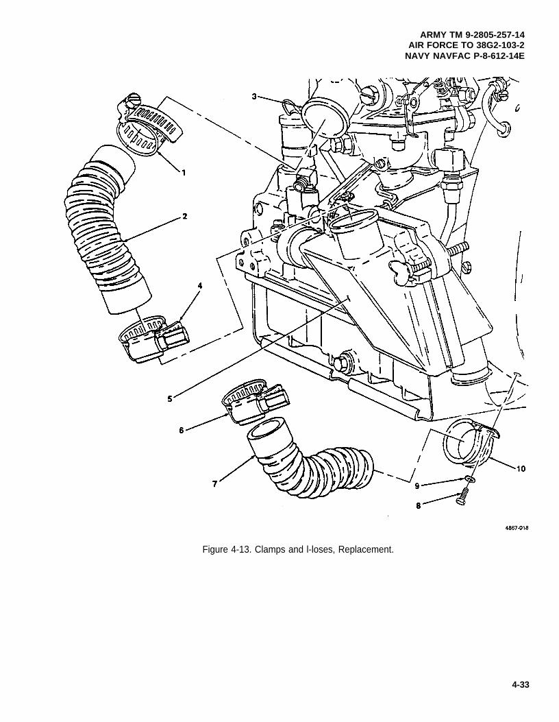
ARMY TM 9-2805-257-14AIR FORCE TO 38G2-103-2
NAVY NAVFAC P-8-612-14E
Figure 4-13. Clamps and l-loses, Replacement.
4-33
ARMY TM 9-2805-257-14AIR FORCE TO 38G2-103-2NAVY NAVFAC P-8-612-14E
4-23. Air Cleaner Element.
This task covers: a. Removal (oil bath) c. Removal (dry)b. Installation (oil bath) d. Installation (dry)
INITIAL SETUP
Tools Materials/Parts
General Mechanic’s Tool Kit (Item 1, Appendix B) Rags, Wiping (Item 6, Appendix D)Solvent, Drycleaning (Item 7, Appendix D)Oil, OH/HDO 15W-40 (Item 2, Appendix D)
a. Removal. Oil Bath. (figure 4-14)
(1) Open two retaining clips (1) securing lower cup (2) and remove.
(2) Pour out oil into suitable container and remove element (3) from lower cup (2).
WARNING
Drycleaning solvent PD-680 used to clean parts is potentially dangerous to personnel andproperty. Avoid repeated and prolonged skin contact. Do not use near open flame orexcessive heat. Flash point of solvent is 100°F-138°F (38°C–60°C).
(3) Clean lower cup with drycleaning solvent and dry thoroughly.
b. Installation. Oil Bath. (figure 4-14)
(1) Place element (3) into lower cup (2) and fill with oil to LEVEL line.
(2) Install lower cup (2) and secure with two retaining clips (1).
4-34
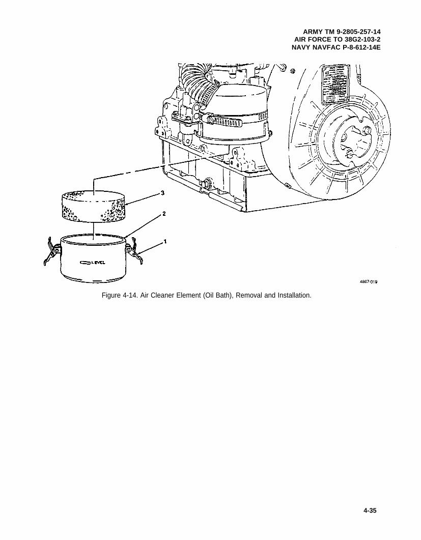
ARMY TM 9-2805-257-14AIR FORCE TO 38G2-103-2
NAVY NAVFAC P-8-612-14E
Figure 4-14. Air Cleaner Element (Oil Bath), Removal and Installation.
4-35
ARMY TM 9-2805-257-14AIR FORCE TO 38G2-103-2NAVY NAVFAC P-8-612-14E
4-23. Air Cleaner Element (cont).
C. Removal. Dry. (figure 4-15)
(1) Loosen two retaining screws (1), open air cleaner assembly (2), and remove element (3).
WARNING
Drycleaning solvent PD-680 used to clean parts is potentially dangerous to personnel andproperty. Avoid repeated and prolonged skin contact. Do not use near open flame orexcessive heat. Flash point of solvent is 100°F–138°F (38°C-60°C).
(2) Clean both halves of air cleaner assembly using drycleaning solvent.
b. Installation. Dry. (figure 4-15)
(1) Position element (3) in air cleaner assembly (2) and secure with two retaining screws (1).
(2) Depress reset button (4) on service indicator (5).
4-36
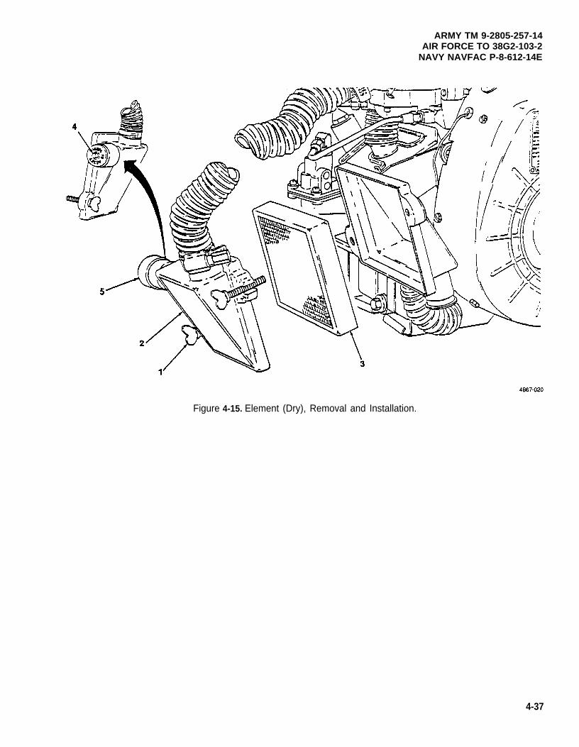
ARMY TM 9-2805-257-14AIR FORCE TO 38G2-103-2
NAVY NAVFAC P-8-612-14E
Figure 4-15. Element (Dry), Removal and Installation.
4-37
ARMY TM 9-2805-257-14AIR FORCE TO 38G2-103-2NAVY NAVFAC P-8-612-14E
4-24. Relief Valve.
This task covers: Replacement
INITIAL SETUP
Tools Materials/Parts
General Mechanic’s Tool Kit (Item 1, Appendix B) Rags, Wiping (Item 6, Appendix D)Solvent, Drycleaning (Item 7, Appendix D)
Replacement. (figure 4-15)
(1)
(2)
(3)
(4)
(5)
(6)
4-38
Remove any dirt or debris from around relief valve (1).
Unscrew relief valve (1) from rocker cover (2)
WARNING
Drycleaning solvent PD-680 used to clean parts is potentially dangerous to personnel andproperty. Avoid repeated and prolonged skin contact. Do not use near open flame orexcessive heat. Flash point of solvent is 100°F-138°F (38°C-60°C).
Clean relief valve (1) with drycleaning solvent and dry thoroughly.
Ensure pin (3) moves in and out freely
Replace relief valve (1) if damaged.
Install relief valve (1) in rocker cover (2).
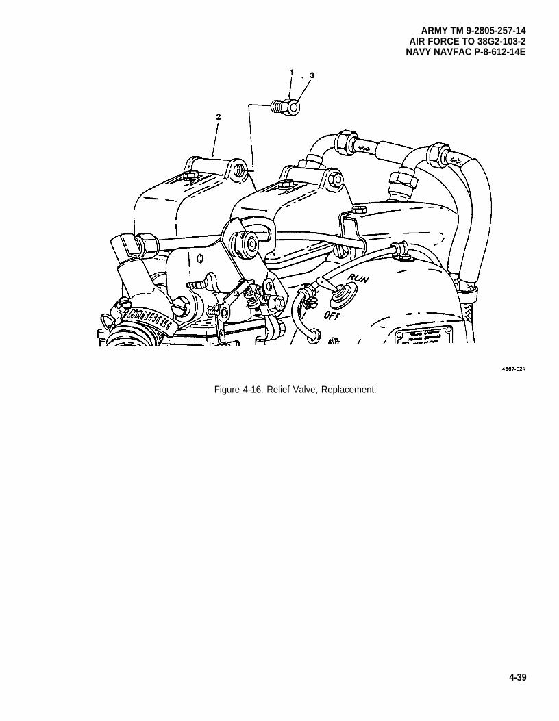
ARMY TM 9-2805-257-14AIR FORCE TO 38G2-103-2
NAVY NAVFAC P-8-612-14E
Figure 4-16. Relief Valve, Replacement.
4-39
ARMY TM 9-2805-257-14AIR FORCE TO 38G2-103-2NAVY NAVFAC P-8-612-14E
4-25. Rocker Cover.
This task covers: a. Removal b. Repair c. Installation
INITIAL SETUP
Tools Equipment Condition
General Mechanic’s Tool Kit (Item 1, Appendix B) Cylinder head covers removed (para. 4-15).
Materials/Parts
Rags, Wiping (Item 6, Appendix D)Solvent, Drycleaning (Item 7, Appendix D)Gasket, Rocker Cover Mounting
(NSN 5330-00-797-4642)
a. Removal. (figure 4-16)
NOTE
There are two rocker covers on this engine, the removal,procedures are the same for both.
repair, and installation
Remove screw (1) and plastic washer (2) and remove cover (3) and gasket (4).
b. Repair.
(1)
(2)
(3)
(4)
WARNING
Drycleaning solvent PD-680 used to clean parts is potentially dangerous to personnel andproperty. Avoid repeated and prolonged skin contact. Do not use near open flame orexcessive heat. Flash point of solvent is 100°F-138°F (38°C–60°C).
Clean rocker cover using drycleaning solvent.
Replace plastic washer (2) if cracked or otherwise damaged.
Replace gasket (4) if torn or otherwise damaged.
Repair all dents, and paint cover as necessary.
c. Installation. (figure 4-17)
Position rocker cover (3) and gasket (4) on engine, and secure with screw (1) and plastic washer (2).
4-40
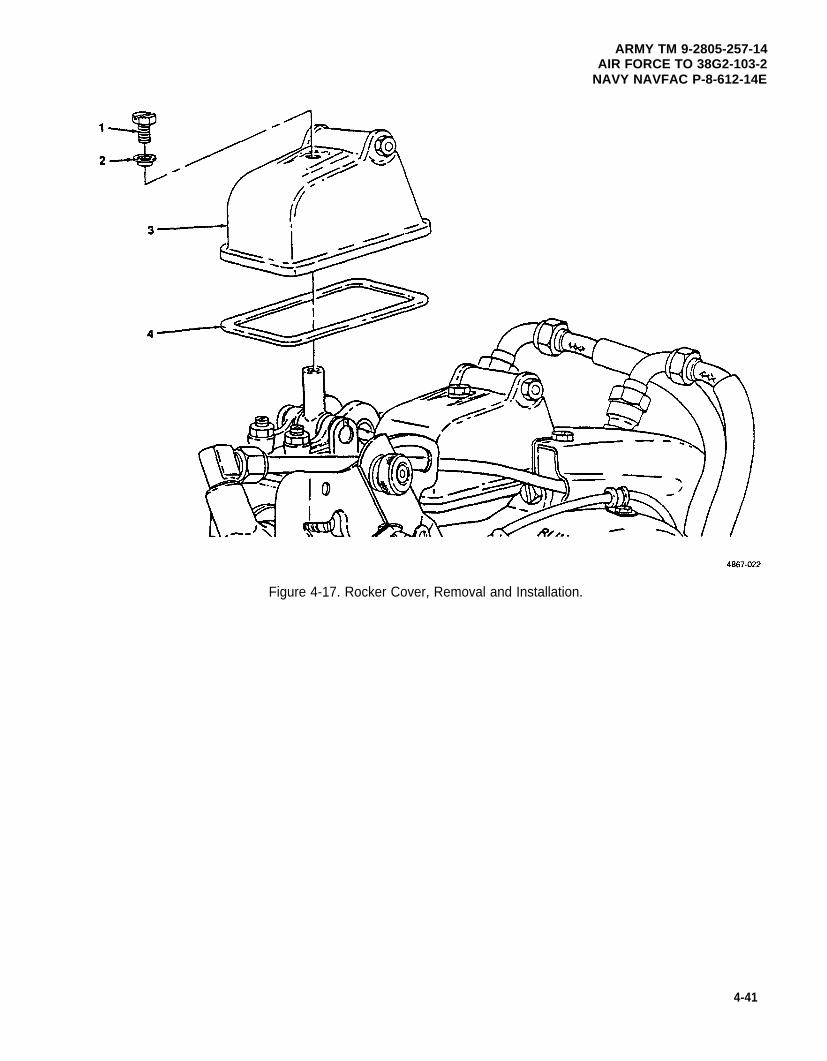
ARMY TM 9-2805-257-14AIR FORCE TO 38G2-103-2
NAVY NAVFAC P-8-612-14E
Figure 4-17. Rocker Cover, Removal and Installation.
4-41
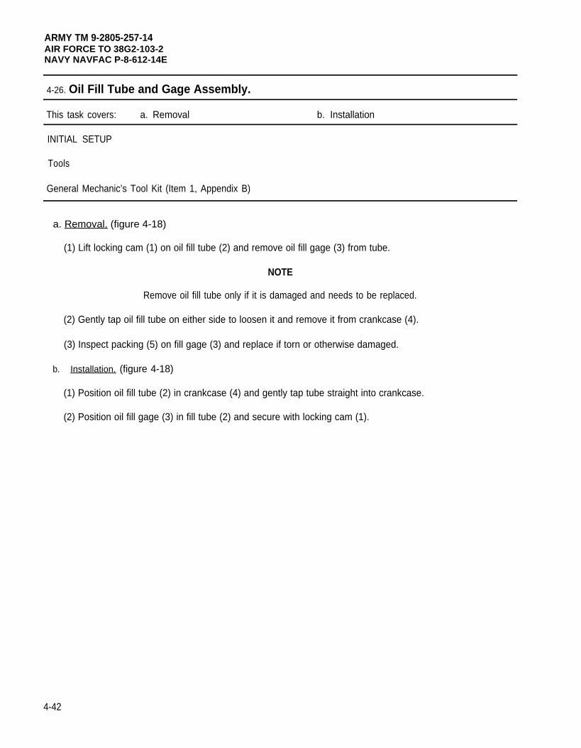
ARMY TM 9-2805-257-14AIR FORCE TO 38G2-103-2NAVY NAVFAC P-8-612-14E
4-26. Oil Fill Tube and Gage Assembly.
This task covers: a. Removal b. Installation
INITIAL SETUP
Tools
General Mechanic’s Tool Kit (Item 1, Appendix B)
a. Removal. (figure 4-18)
(1) Lift locking cam (1) on oil fill tube (2) and remove oil fill gage (3) from tube.
NOTE
Remove oil fill tube only if it is damaged and needs to be replaced.
(2) Gently tap oil fill tube on either side to loosen it and remove it from crankcase (4).
(3) Inspect packing (5) on fill gage (3) and replace if torn or otherwise damaged.
b. Installation. (figure 4-18)
(1) Position oil fill tube (2) in crankcase (4) and gently tap tube straight into crankcase.
(2) Position oil fill gage (3) in fill tube (2) and secure with locking cam (1).
4-42
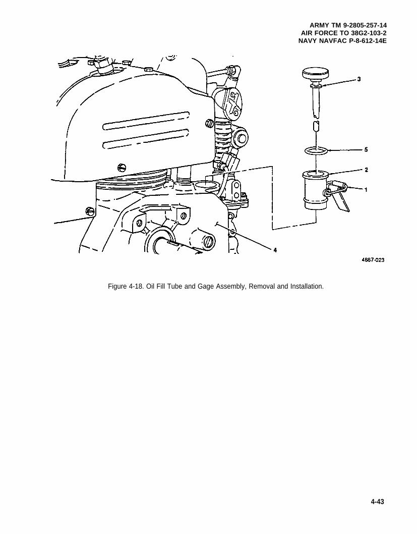
ARMY TM 9-2805-257-14AIR FORCE TO 38G2-103-2
NAVY NAVFAC P-8-612-14E
Figure 4-18. Oil Fill Tube and Gage Assembly, Removal and Installation.
4-43
ARMY TM 9-2805-257-14AIR FORCE TO 38G2-103-2NAVY NAVFAC P-8-612-14E
4-27. Governor Assembly.
This task covers: Adjustment
INITIAL SETUP
Tools Materials/Parts (cont)
General Mechanic’s Tool Kit (Item 1, Appendix B) Gasket, Throttle Housing to Carburetor(P/N 9786E65-4)
Materials/Parts Gasket, Throttle Housing Rear (PIN 9786E65-3)Gasket, Throttle Housing Front (P/N 9786E64-6)
Rags, Wiping (Item 6, Appendix D)Solvent, Drycleaning (Item 7, Appendix D)
a. Adjustment. (figure 4-19)
(1) Remove two screws (1) and washers (2) securing throttle housing cover (3) and remove cover and gasket(4).
(2) Remove screw (5) and washer (6) securing throttle lever (7) to carburetor throttle rod (8) and remove leverfrom rod.
(3) Loosen clamp (9) on governor control rod housing (10) and remove control rod housing (10) from throttlehousing (11).
(4) Remove two screws (12) and washers (13) securing throttle housing (11) to carburetor (14) and removethrottle housing (11 ), gasket (15) rear cover (16), and gasket (17).
(5) Hold carburetor throttle (18) 1/16 infrom the open position, loosen lock nut (19) on control rod (20), and adjustclevis (21) until throttle lever (7) fits onto carburetor throttle rod (8).
(6) Tighten lock nut (19).
(7) Install gasket (17), rear cover (16), gasket (15), throttle housing (11) and secure using two screws (12) andwashers (13).
(8) Install governor control rod housing (10) on throttle housing (11) and secure with clamp (9).
(9) Install throttle lever (7) on carburetor throttle rod (8) and secure with screw (5) and washer (6).
(10) Install throttle housing cover (3) and gasket (4) on throttle housing (11) and secure with two screws (1) andwashers (2).
(11) Start engine (para2-9).
4-44 Change 2
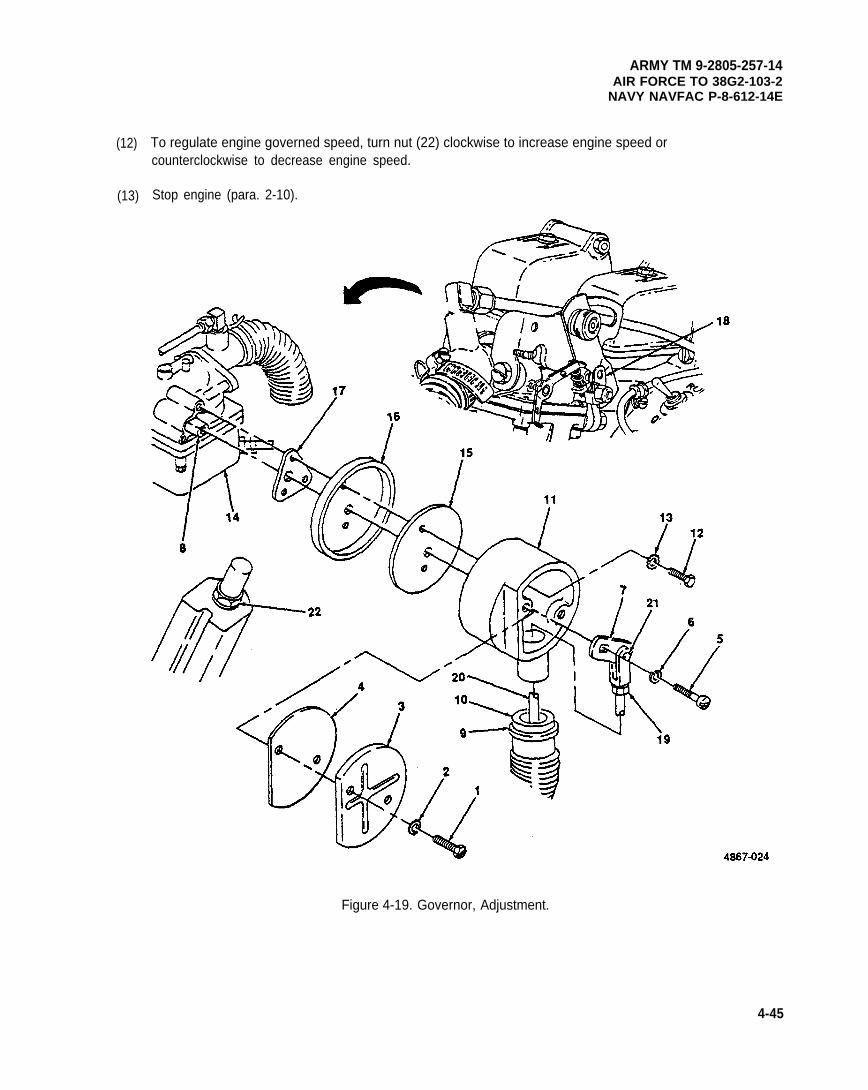
(12)
(13)
ARMY TM 9-2805-257-14AIR FORCE TO 38G2-103-2
NAVY NAVFAC P-8-612-14E
To regulate engine governed speed, turn nut (22) clockwise to increase engine speed orcounterclockwise to decrease engine speed.
Stop engine (para. 2-10).
Figure 4-19. Governor, Adjustment.
4-45
ARMY TM 9-2805-257-14AIR FORCE TO 38G2-103-2NAVY NAVFAC P-8-612-14E
4-28. Breaker Points Cover (Breaker Point Ignition).
This task covers: a. Removal b. Inspect c. Installation
INITIAL SETUP
Tools Materials/Parts
General Mechanic’s Tool Kit (Item 1, Appendix B) Rags, Wiping (Item 6, Appendix D)Solvent, Drycleaning (Item 7, Appendix D)Gasket, Breaker Point Cover Mounting
(NSN 5330-00-103-8793)
a. Removal. (figure 4-20)
(1) Unsnap two clips (1) securing breaker points cover (2) and remove cover (2) and gasket (3).
(2) Remove nut (4) and washer (5) securing ground strap (6) to cover.
(3) Remove screw (7) plastic washer (8), and nut (9).
b. Inspection.
(1) Inspect gasket (3) for wear or other damage and replace as needed.
(2) Inspect plastic washer (8) and replace if cracked or otherwise damaged.
c. Installation. (figure 4-20)
(1)
(2)
(3)
4-46
Install screw (7), plastic washer (8), and nut (9) in cover (2).
Install ground strap (6) on cover and secure with washer (5) and nut (4).
Position cover (2) and gasket (3) on engine and secure with two clips (1).
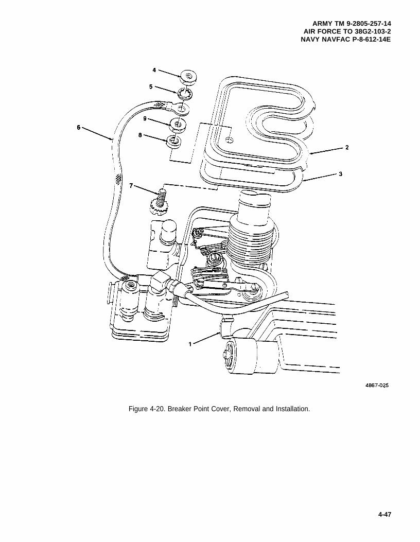
ARMY TM 9-2805-257-14AIR FORCE TO 38G2-103-2
NAVY NAVFAC P-8-612-14E
4-47
Figure 4-20. Breaker Point Cover, Removal and Installation.
ARMY TM 9-2805-257-14AIR FORCE TO 38G2-103-2NAVY NAVFAC P-8-612-14E
4-29. Breaker Points Assembly (Breaker Point Ignition).
This task covers: a. Removal b. Inspection c. Installation
INITIAL SETUP
Tools Materials/Parts
General Mechanic’s Tool Kit (Item 1, Appendix B) Rags, Wiping (Item 6, Appendix D)Oil, Engine 15W-40 (Item 2, Appendix D)
NOTE
This engine is equpped with two sets of breaker points. The following procedures are thesame for both sets.
a. Removal. (figure 4-21)
(1)
(2)
(3)
Unsnap two clips (1) securing breaker points cover (2) and move cover out of way.
Remove screw (3) and Iockwasher (4) and move connector bar (5) out of way.
Remove two screws (7) and washers (8) and remove breaker points (6).
b. Inspection. (figure 4-21)
(1) Inspect contacts (9) for pits or other signs of wear, and replace breaker points as needed.
(2) Inspect cam follower (10) for cracks or wear. Replace breaker points as needed.
c. Installation. (figure 4-21)
(1)
(2)
(3)
(4)
(5)
(6)
(7)
4-48
NOTE
Do not tighten right hand mounting screw fully at this time.
Position breaker points (6) in governor housing (11) and secure with two screws (7) and washers (8).
Rotate engine by hand until cam follower (10) is on highest point of ignition cam (12).
Adjust point gap to .016 -0.20 in. (.040 -.050 cm) and tighten right hand screw.
Recheck point gap and adjust as needed.
Install connector bar (5) and secure with screw (3) and washer (4).
Use clean engine oil and lubricate ignition cam wick (13) sparingly.
Install breaker point cover (2) and secure with two clips (1).
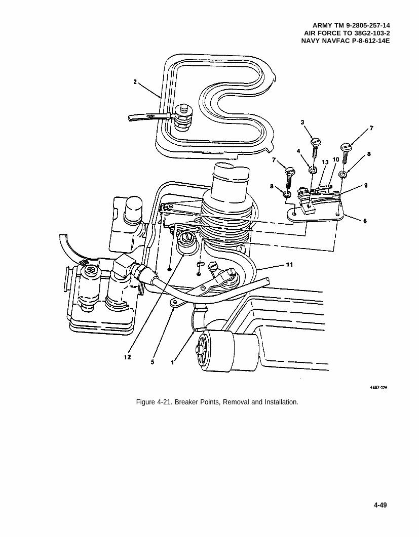
ARMY TM 9-2805-257-14AIR FORCE TO 38G2-103-2
NAVY NAVFAC P-8-612-14E
Figure 4-21. Breaker Points, Removal and Installation.
4-49
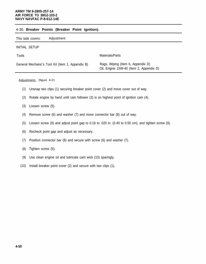
ARMY TM 9-2805-257-14AIR FORCE TO 38G2-103-2NAVY NAVFAC P-8-612-14E
4-30. Breaker Points (Breaker Point Ignition).
This task covers: Adjustment
INITIAL SETUP
Tools Materials/Parts
General Mechanic’s Tool Kit (item 1, Appendix B) Rags, Wiping (Item 6, Appendix D)Oil, Engine 15W-40 (Item 2, Appendix D)
Adjustment. (figure 4-21
(1)
(2)
(3)
(4)
(5)
(6)
(7)
(8)
(9)
(10)
4-50
Unsnap two clips (1) securing breaker point cover (2) and move cover out of way.
Rotate engine by hand until cam follower (3) is on highest point of ignition cam (4).
Loosen screw (5).
Remove screw (6) and washer (7) and move connector bar (8) out of way.
Loosen screw (9) and adjust point gap to 0.16 to .020 in. (0.40 to 0.50 cm), and tighten screw (9).
Recheck point gap and adjust as necessary.
Position connector bar (8) and secure with screw (6) and washer (7).
Tighten screw (5).
Use clean engine oil and lubricate cam wick (10) sparingly.
Install breaker point cover (2) and secure with two clips (1).
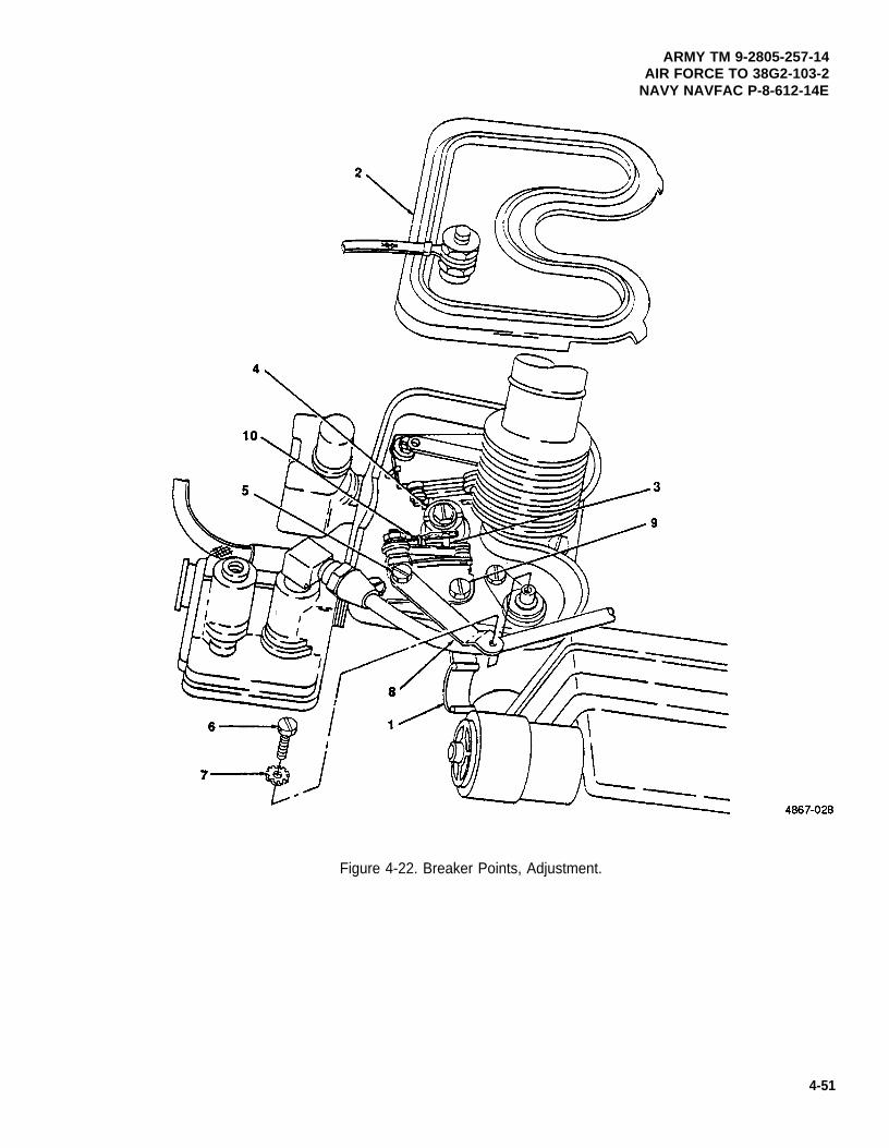
ARMY TM 9-2805-257-14AIR FORCE TO 38G2-103-2
NAVY NAVFAC P-8-612-14E
Figure 4-22. Breaker Points, Adjustment.
4-51
ARMY TM 9-2805-257-14AIR FORCE TO 38G2-103-2NAVY NAVFAC P-8-612-14E
4-31. Condenser (Breaker Point Ignition).
This task covers: a. Removal b. Installation
INITIAL SETUP
Tools
General Mechanic’s Tool Kit (Item 1, Appendix B)
NOTE
This engine is equipped with two condensers. The removal and installation proceduresare the same for both condensers.
a. Removal. (figure 4-23)
(1)
(2)
(3)
(4)
Unsnap two clips (1) securing breaker points cover (2) and move out of way.
Remove screw (3) and washer (4) and remove connector bar (5) from top of condenser (6).
Trace condenser lead (7) to suppression unit (8) and remove nut (9) and washer (10) and removecondenser lead (7).
Remove screw (11 ) and washer (12) and remove condenser (6).
b. Installation . (figure 4-23)
(1) Install condenser (6) and secure with screw (11) and washer (12).
(2) Install condenser lead (7) on suppression unit (8) and secure with nut (9) and washer (10).
(3) Install connector bar (5) and secure with screw (3) and washer (4).
(4) Install breaker points cover (2) and secure with two clips (1).
4-52
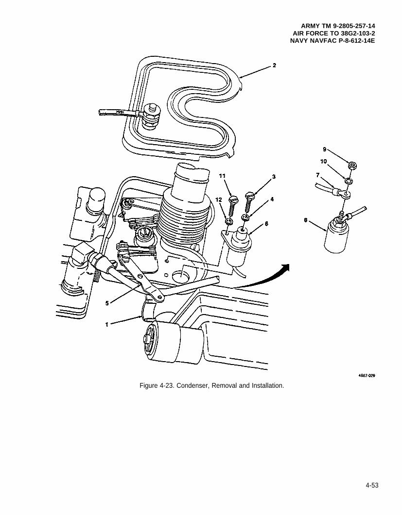
Figure 4-23. Condenser, Removal and Installation.
ARMY TM 9-2805-257-14AIR FORCE TO 38G2-103-2
NAVY NAVFAC P-8-612-14E
4-53
ARMY TM 9-2805-257-14AIR FORCE TO 38G2-103-2NAVY NAVFAC P-8-612-14E
4-32. Breather Line.
This task covers: a. Removal (oil bath) d. Removal (dry)b. Inspection (oil bath) e. Inspection (dry)c. Installation (oil bath) f. Installation (dry)
INITIAL SETUP
Tools Equipment Condition
General Mechanic’s Tool Kit (Item 1, Appendix B) Cylinder head covers removed (para. 4-15).
Materials/Parts
Rags, Wiping (Item 6, Appendix D)Solvent, Drycleaning (Item 7, Appendix D)Rubber Sleeve (NSN 5365-00-215-7421)
a. Removal. Oil Bath. (figure 4-24)
(1) Loosen coupling nut (1) on crankshaft side rocker cover (2).
(2) Loosen coupling nut (3) on flywheel side rocker cover (4).
(3) Loosen coupling nut (5) on air cleaner (6) and remove breather line (7).
(4) Remove coupling nut (5) and rubber sleeve (8) from breather line (7).
b. Inspection.
(1)
(2)
(3)
(4)
4-54
WARNING
Drycleaning solvent PD-680 used to clean parts is potentially dangerous to personnel andproperty. Avoid repeated and prolonged skin contact. Do not use near open flame orexcessive heat. Flash point of solvent is 100°F-138°F (38°C-60°C).
Clean breather line and coupling nut with dry cleaning solvent and dry thoroughly
Ensure there are no obstructions in breather line.
Inspect coupling nuts (1), (3) and (5) for signs of stripped threads or other damage, and replace breatherline if damage is found.
Inspect rubber sleeve (8) replace if ripped or otherwise damaged.
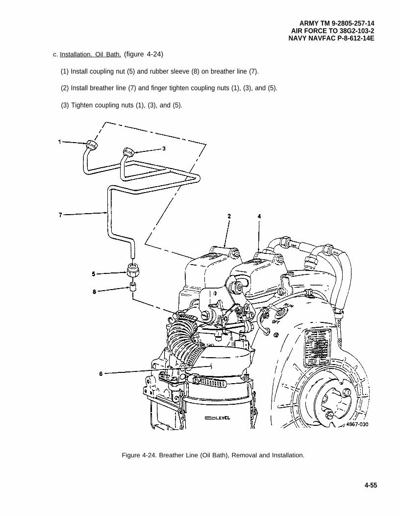
ARMY TM 9-2805-257-14AIR FORCE TO 38G2-103-2
NAVY NAVFAC P-8-612-14E
c. Installation. Oil Bath. (figure 4-24)
(1) Install coupling nut (5) and rubber sleeve (8) on breather line (7).
(2) Install breather line (7) and finger tighten coupling nuts (1), (3), and (5).
(3) Tighten coupling nuts (1), (3), and (5).
Figure 4-24. Breather Line (Oil Bath), Removal and Installation.
4-55
ARMY TM 9-2805-257-14AIR FORCE TO 38G2-103-2NAVY NAVFAC P-8-612-14E
4-32. Breather Line (cont).
d. Removal. Dry. (figure 4-25)
(1) Loosen coupling nut (1) at crankshaft side cylinder head adapter fitting (2).
(2) Loosen coupling nut (3) at flywheel side cylinder head adapter fitting (2).
(3) Loosen coupling nut (4) at air intake elbow (5) and remove breather line (6).
(4) Remove coupling nut (4) and rubber sleeve (7) from breather line (6).
(5) Remove two adapter fittings (2) from cylinder heads (8).
(6) Remove an intake elbow (5).
e. Inspection.
WARNING
(1)
(2)
(3)
(4)
(5)
Drycleaning solvent PD-680 used to clean parts is potentially dangerous to personnel andproperty. Avoid repeated and prolonged skin contact. Do not use near open flame orexcessive heat. Flash point of solvent is 100°F-138°F (38°C-60°C).
Clean breather line and coupling nut with dry cleaning solvent and dry thoroughly.
Ensure there are no obstructions in breather line.
Inspect coupling nuts (1), (3) and (4) for signs of stripped threads or other damage, and replace breatherline if damaged.
Inspect rubber sleeve (7) and replace if torn or damaged.
Inspect adapter fittings (2) for signs of stripped threads or other damage, and replace if damaged.
f. Installation. Dry. (figure 4-25)
(1) install air intake elbow (5).
(2) Install two adapter fittings (2) into cylinder heads (8) and tighten.
(3) Install rubber sleeve (7) and coupling nut (4) onto breather line (6).
(4) Position breather line (6) on cylinder heads (8) and finger tighten coupling nuts (1) and (3).
(5) Position breather line (6) on air intake elbow (5) and finger tighten coupling nut (4).
(6) Tighten coupling nuts (1), (3), and (4).
4-56
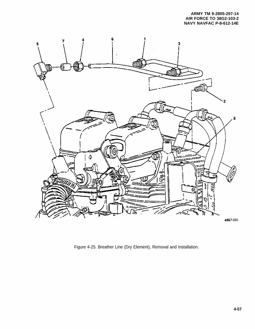
ARMY TM 9-2805-257-14AIR FORCE TO 38G2-103-2
NAVY NAVFAC P-8-612-14E
Figure 4-25. Breather Line (Dry Element), Removal and Installation.
4-57
ARMY TM 9-2805-257-14AIR FORCE TO 38G2-103-2NAVY NAVFAC P-8-612-14E
4-33. Throttle Control.
This task covers: a. Removal b. Installation
INITIAL SETUP
Tools
General Mechanic’s Tool Kit (Item 1, Appendix B)
a. Removal. (figure 4-26)
(1) Remove screw (1) and washer (2).
NOTE
Make note of spring placement before removal of throttle lever.
(2) Remove nut (3) and remove throttle lever (4) and spring (5).
(3) Remove screw (6) and remove throttle control (7).
b. Installation. (figure 4-26)
(1)
(2)
(3)
(4)
4-58
Install spring (5) on throttle rod (9).
Position throttle control (7) on carburetor (8) and secure with screw (6).
Rotate spring (5) counterclockwise half turn and install throttle lever (4) on throttle rod (9) and securewith nut (3).
Install screw (1) and washer (2).
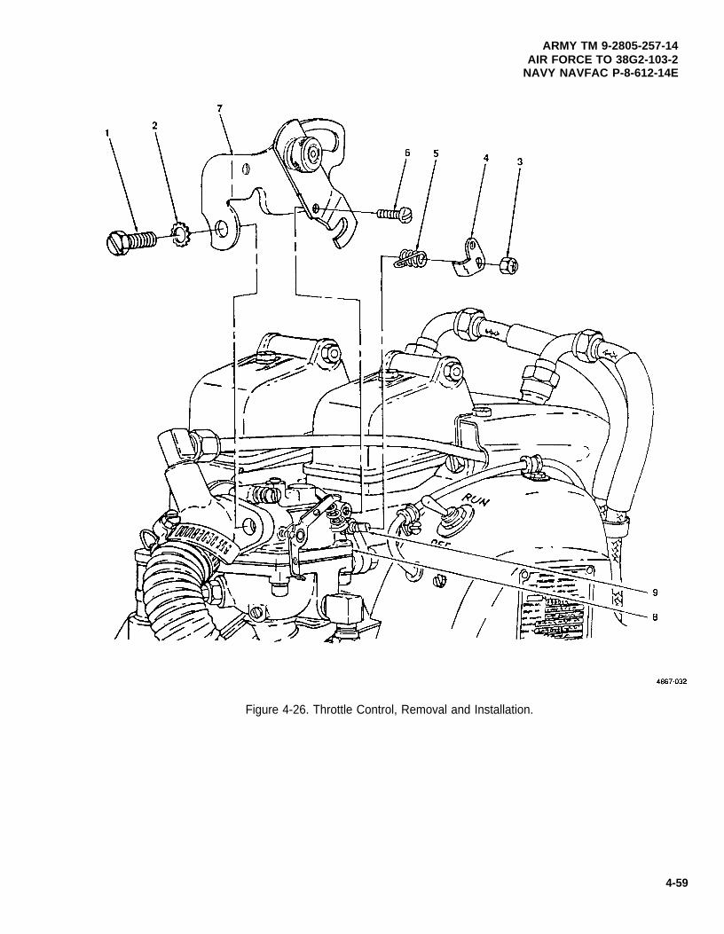
ARMY TM 9-2805-257-14AIR FORCE TO 38G2-103-2
NAVY NAVFAC P-8-612-14E
Figure 4-26. Throttle Control, Removal and Installation.
4-59
ARMY TM 9-2805-257-14AIR FORCE TO 38G2-103-2NAVY NAVFAC P-8-612-14E
4-34. Carburetor.
This task covers: a. Adjustment c. Inspectionb. Removal d. Installation
INITIAL SETUP
Tools Materials/Parts (cont)
General Mechanic’s Tool Kit (Item 1, Appendix B) Gasket, Carburetor Mounting (NSN 5330-00-819-8733)Wrench, Torque (NSN 5120-00-640-6364) Gasket, Throttle Housing Front (P/N 9786E64-6)
(Item 2, Appendix B) Gasket, Throttle Housing Rear (P/N 9786E65-3)Gasket, Throttle Housing to Carburetor
Materials/Parts (P/N 9786E65-4)
Rags, Wiping (Item 6, Appendix D)Solvent, Drycleaning (Item 7, Appendix D)
a. Adjustment. (figure 4-27)
(1)
(2)
(3)
(4)
(5)
(6)
(7)
(8)
(9)
4-60
Turn main adjustment needle (1) and idle adjustment needle (2) fully clockwise to stop.
Turn main adjustment needle (1) 3/4 turns counterclockwise.
Turn idle adjustment (2) 1/2 turns counterclockwise.
Start and warm-up engine (para. 2-9).
Apply end item load and observe exhaust.
If exhaust is black, turn main adjustment needle (1) clockwise.
If engine runs rough or lacks power, turn main adjustment needle (1) counterclockwise.
To set idle speed, turn idle speed regulating screw (3) clockwise to increase idle or counterclockwise todecrease.
Stop engine (para. 2-10).
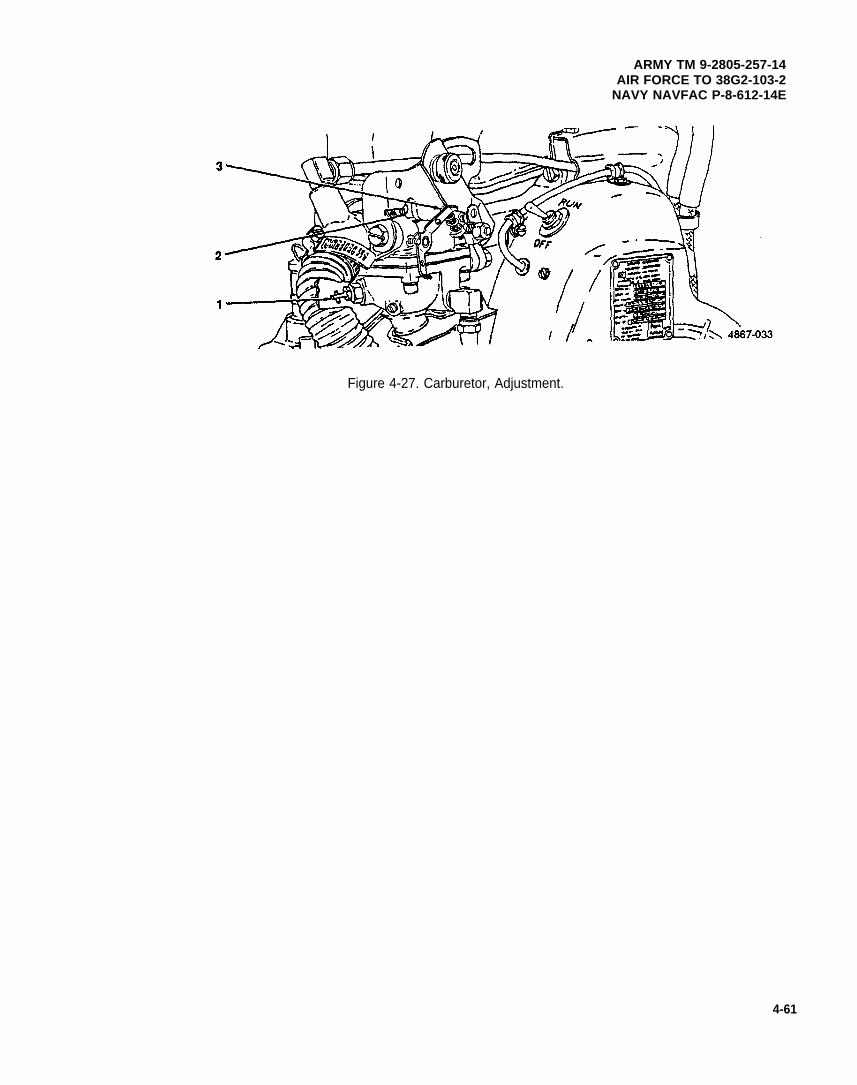
ARMY TM 9-2805-257-14AIR FORCE TO 38G2-103-2
NAVY NAVFAC P-8-612-14E
Figure 4-27. Carburetor, Adjustment.
4-61
ARMY TM 9-2805-257-14AIR FORCE TO 38G2-103-2NAVY NAVFAC P-8-612-14E
4-34. Carburetor (cont).
b. Removal. (figure 4-28)
(1)
(2)
(3)
(4)
(5)
(6)
(7)
(8)
(9)
Remove throttle control (para. 4-33).
Disconnect breather line (1) from air intake elbow (2).
Loosen clamp (3) and remove air cleaner duct (4) from air intake elbow (2).
Remove screw (5) and washers (6) and remove air intake elbow (2) and gasket (7).
Remove two screws (8) and washers (9) and remove throttle housing cover (10) and gasket (11).
Remove screw (12) , washer (13) and remove throttle lever (14) from carburetor (15).
Remove two screws (16), washers (17) and remove throttle housing (18), gasket (19), rear cover (20)and gasket (21).
Disconnect fuel line (22) from carburetor (15).
Remove two nuts (23) and washers (24) securing carburetor (15) to intake manifold (25) and removecarburetor (15) and gasket (26).
WARNING
Drycleaning solvent PD-680 used to clean parts is potentially dangerous to personnel andproperty. Avoid repeated and prolonged skin contact. Do not use near open flame orexcessive heat. Flash point of solvent is 100°F-138°F (38°C-60°C).
c. Inspection.
(1)
(2)
(3)
4-62
Clean carburetor with drycleaning solvent, and dry thoroughly.
Inspect carburetor for cracks, excessive wear, stripped threads or any other signs of damage andreplace as needed.
Clean all gasket surfaces and ensure that old gasket material is removed.
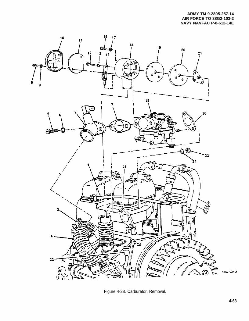
ARMY TM 9-2805-257-14AIR FORCE TO 38G2-103-2
NAVY NAVFAC P-8-612-14E
Figure 4-28. Carburetor, Removal.
4-63
ARMY TM 9-2805-257-14AIR FORCE TO 38G2-103-2NAVY NAVFAC P-8-612-14E
4-34. Carburetor (cont).
d. Installation. (figure 4-29)
(1)
(2)
(3)
(4)
(5)
(6)
(7)
(8)
(9)
(10)
4-64
Position carburetor (15) and gasket (26) on intake manifold (25) and secure with two nuts (23) andwashers (24).
Connect fuel line (22) to carburetor (15).
Position gasket (21), rear cover (20), gasket (19) and throttle housing (18) on carburetor (15) and securewith two screws (16) and washers (17).
Position throttle lever (14) on carburetor (15) and secure with screw (12) and washer (13).
Position gasket (11) and throttle housing cover (10) on throttle housing (18) and secure with two screws(8) and washers (9).
Position air intake elbow (2) and gasket (7) on carburetor (15) and secure with screw (5) and washer (6).
Connect breather line (1) to air intake elbow (2).
Install air cleaner duct (4) on air intake elbow (2) and secure with clamp (3).
Install throttle control (para. 4-33).
Adjust carburetor.
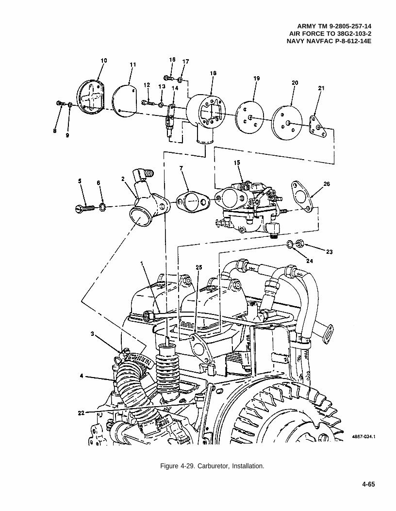
ARMY TM 9-2805-257-14AIR FORCE TO 38G2-103-2
NAVY NAVFAC P-8-612-14E
Figure 4-29. Carburetor, Installation.
4-65
ARMY TM 9-2805-257-14AIR FORCE TO 38G2-103-2NAVY NAVFAC P-8-612-14E
4-35. Fuel Pump.
This task covers: a. Test b. Removal c. Installation
INITIAL SETUP
Tools Equipment Condition
General Mechanic’s Tool Kit (Item 1, Appendix B) Fuel supply removed from engine for removal of fuelTest, Engine Vacuum and Pressure pump.
(NSN 4910-00-253-8673) (Item 2, Appendix B)
Materials/Parts
Gasket, Fuel Pump Mounting (NSN 5330-00-756-1673)
a. Test. (figure 4-30)
(1)
(2)
(3)
(4)
(5)
Disconnect fuel line (1) from fuel pump (2).
Connect suitable fuel pressure gage (3) to fuel pump (2).
Use starting rope to crank engine and check fuel pressure gage. Fuel pressure should be between 11/2-3 psi (10.34-20.69 Kpas).
Replace fuel pump if actual reading does not match specifications.
Remove pressure gage (3) and connect fuel line (1) to fuel pump (2).
4-66
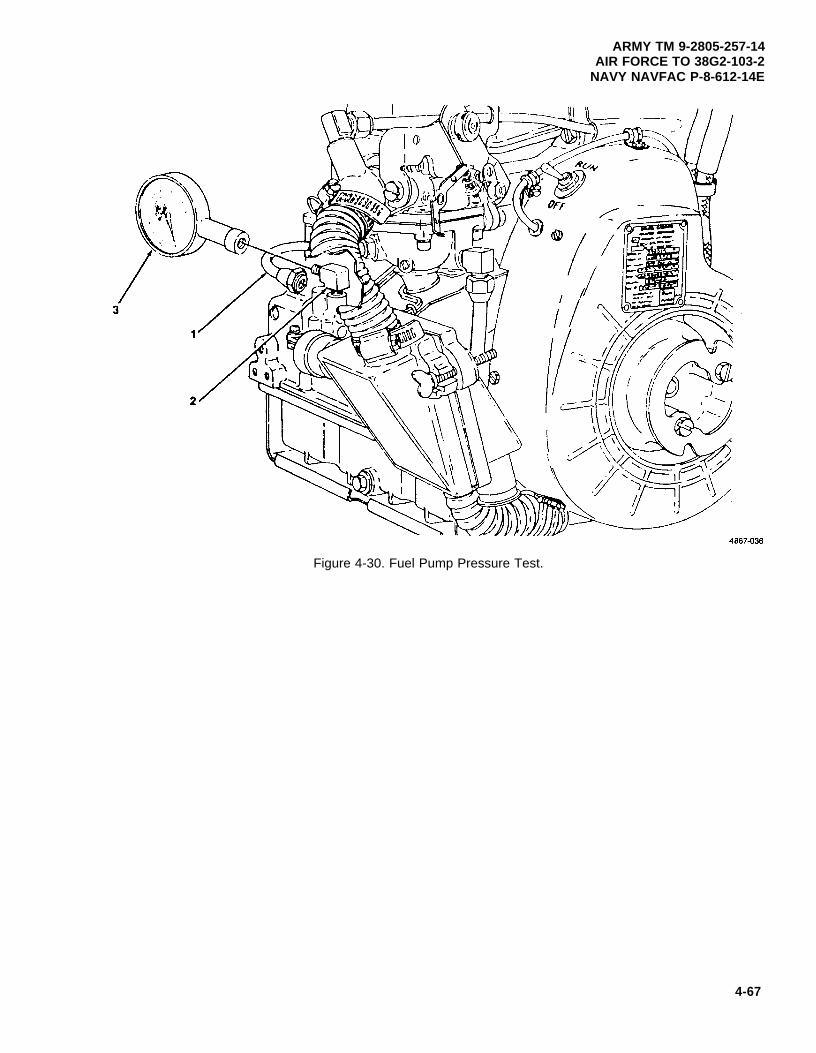
ARMY TM 9-2805-257-14AIR FORCE TO 38G2-103-2
NAVY NAVFAC P-8-612-14E
Figure 4-30. Fuel Pump Pressure Test.
4-67
ARMY TM 9-2805-257-14AIR FORCE TO 38G2-103-2NAVY NAVFAC P-8-612-14E
4-35.
b.
Fuel Pump (cont).
Removal. (figure 4-31)
(1) Loosen fuel line (1) at elbow (2) on fuel pump (3).
NOTE
Perform step 2 only if fuel pump is being replaced.
(2) Remove elbow (2) from fuel pump (3).
(3) Remove two screws (4) and washers (5) securing fuel pump (3) and remove pump and gasket (6).
c. Installation. (figure 4-31)
(1) Clean mounting surface on engine and fuel pump.
(2) Position fuel pump (3) with gasket (6) on engine and secure with two screws (4) and washers (5).
(3) Install elbow (2) on fuel pump (3) and aline it with fuel line fitting (1).
(4) Connect fuel line (1) to elbow (2) on fuel pump (3).
4-68
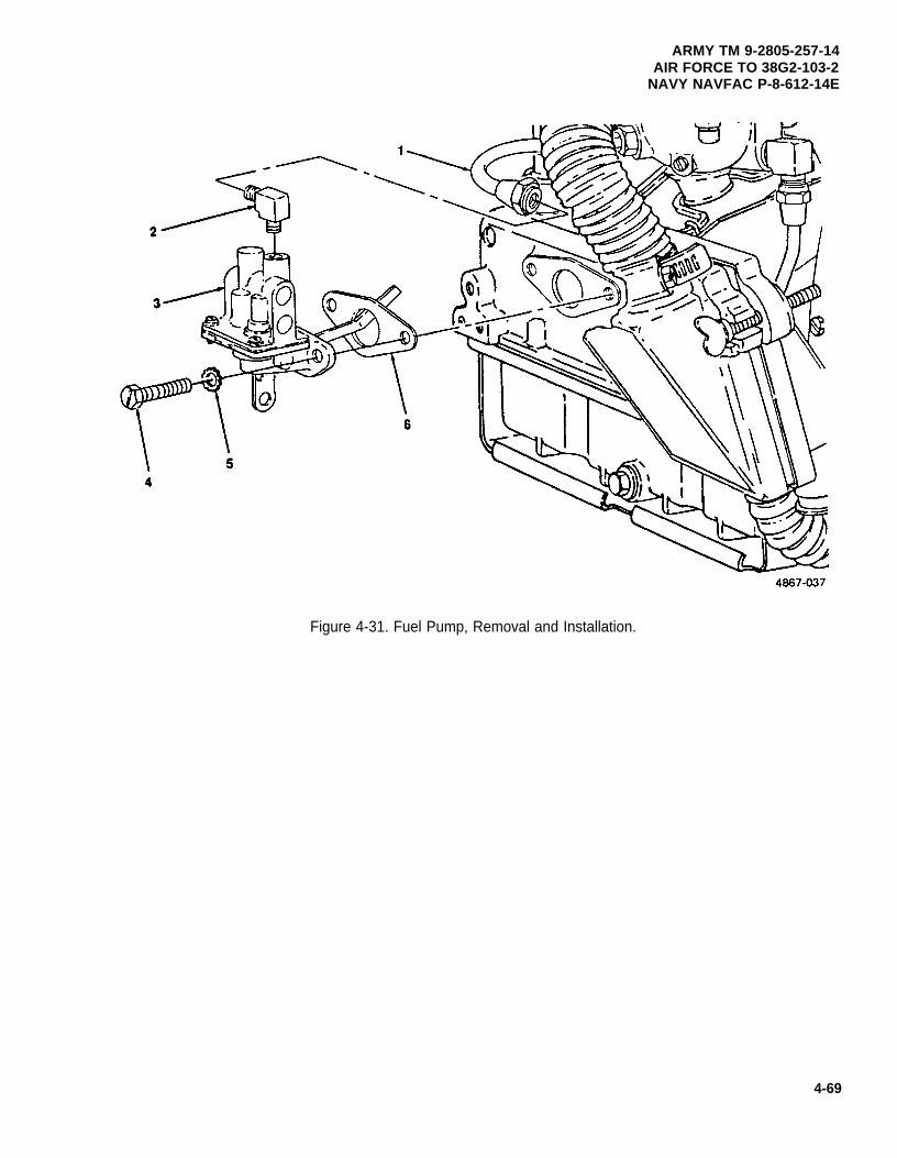
ARMY TM 9-2805-257-14AIR FORCE TO 38G2-103-2
NAVY NAVFAC P-8-612-14E
Figure 4-31. Fuel Pump, Removal and Installation.
4-69
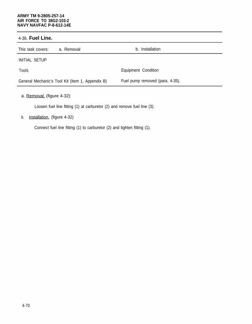
ARMY TM 9-2805-257-14AIR FORCE TO 38G2-103-2NAVY NAVFAC P-8-612-14E
4-36. Fuel Line.
This task covers: a. Removal b. Installation
INITIAL SETUP
Tools Equipment Condition
General Mechanic’s Tool Kit (Item 1, Appendix B) Fuel pump removed (para. 4-35).
a. Removal. (figure 4-32)
Loosen fuel line fitting (1) at carburetor (2) and remove fuel line (3).
b. Installation. (figure 4-32)
Connect fuel line fitting (1) to carburetor (2) and tighten fitting (1).
4-70
ARMY TM 9-2805-257-14AIR FORCE TO 38G2-103-2
NAVY NAVFAC P-8-612-14E
Figure 4-32. Fuel Line, Removal and Installation.
4-71
ARMY TM 9-2805-257-14AIR FORCE TO 38G2-103-2NAVY NAVFAC P-8-612-14E
4-37. Starter Flange.
This task covers: a. Removal b. Installation
INITIAL SETUP
Tools
General Mechanic’s Tool Kit (Item 1, Appendix B)
a. Removal. (figure 4-33)
Remove two screws (1) and washers (2) and remove starter flange (3) from flywheel (4).
b. Installation. (figure 4-33)
Position starter flange (3) on flywheel (4) and secure with two screws (1) and washers (2).
4-72
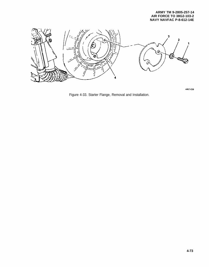
ARMY TM 9-2805-257-14AIR FORCE TO 38G2-103-2
NAVY NAVFAC P-8-612-14E
Figure 4-33. Starter Flange, Removal and Installation.
4-73
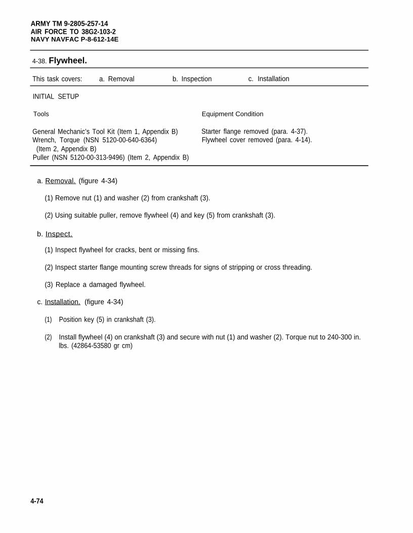
ARMY TM 9-2805-257-14AIR FORCE TO 38G2-103-2NAVY NAVFAC P-8-612-14E
4-38. Flywheel.
This task covers: a. Removal b. Inspection c. Installation
INITIAL SETUP
Tools Equipment Condition
General Mechanic’s Tool Kit (Item 1, Appendix B) Starter flange removed (para. 4-37).Wrench, Torque (NSN 5120-00-640-6364) Flywheel cover removed (para. 4-14).
(Item 2, Appendix B)Puller (NSN 5120-00-313-9496) (Item 2, Appendix B)
a. Removal. (figure 4-34)
(1) Remove nut (1) and washer (2) from crankshaft (3).
(2) Using suitable puller, remove flywheel (4) and key (5) from crankshaft (3).
b. Inspect.
(1) Inspect flywheel for cracks, bent or missing fins.
(2) Inspect starter flange mounting screw threads for signs of stripping or cross threading.
(3) Replace a damaged flywheel.
c. Installation. (figure 4-34)
(1)
(2)
4-74
Position key (5) in crankshaft (3).
Install flywheel (4) on crankshaft (3) and secure with nut (1) and washer (2). Torque nut to 240-300 in.lbs. (42864-53580 gr cm)
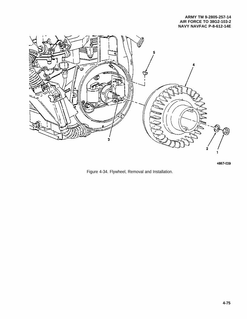
ARMY TM 9-2805-257-14AIR FORCE TO 38G2-103-2
NAVY NAVFAC P-8-612-14E
Figure 4-34. Flywheel, Removal and Installation.
4-75
ARMY TM 9-2805-257-14AIR FORCE TO 38G2-103-2NAVY NAVFAC P-8-612-14E
4-39. Intake Manifold.
This task covers: a. Removal b. Installation
INITIAL SETUP
Tools Equipment Condition
General Mechanic’s Tool Kit (Item 1, Appendix B) Carburetor removed (para. 4-34).Wrench, Torque (NSN 5120-00-640-6364) Cylinder head covers removed (para. 4-15).
(Item 2, Appendix B) Flywheel cover removed (para. 4-16).
Materials/Parts
Rags, Wiping (Item 6, Appendix D)Solvent, Drycleaning (Item 7, Appendix D)Gasket, Intake Manifold Mounting (P/N 9786E26-4)
a. Removal. (figure 4-35)
(1) Remove four screws (1) and washers (2) and remove intake manifold (3) and gaskets (4).
WARNING
Drycleaning solvent PD-680 used to clean parts is potentially dangerous to personnel andproperty. Avoid repeated and prolonged skin contact. Do not use near open flame orexcessive heat. Flash point of solvent is 100°F-138°F (38°C-60°C).
(2) Clean intake manifold (3) with drycleaning solvent and dry thoroughly.
(3) Inspect intake manifold for cracks or other signs of damage and replace if necessary.
b. Installation . (figure 4-35)
(1)
(2)
4-76
Insure gasket surfaces are clean.
Install intake manifold (3) and gaskets (4) and secure with four screws (1) and washers (2). Torquescrews to 40-50 in. Ibs (8037-8930 gr cm).
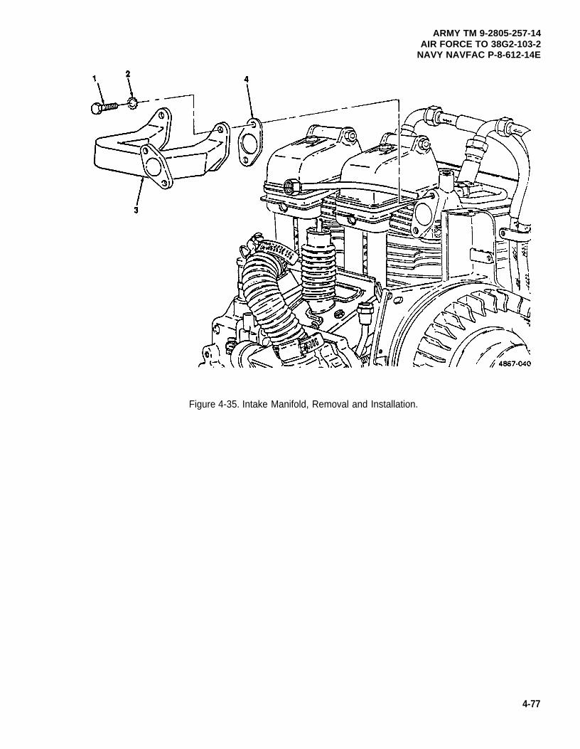
ARMY TM 9-2805-257-14AIR FORCE TO 38G2-103-2
NAVY NAVFAC P-8-612-14E
Figure 4-35. Intake Manifold, Removal and Installation.
4-77
ARMY TM 9-2805-257-14AIR FORCE TO 38G2-103-2NAVY NAVFAC P-8-612-14E
4-40. Exhaust Manifold.
This task covers: a. Removal b. Installation
INITIAL SETUP
Tools Equipment Condition
General Mechanic’s Tool Kit (Item 1, Appendix B) Cylinder head covers removed (para. 4-15).Wrench, Torque (NSN 5120-00-640-6364) Breather line removed (para. 4-32).
(Item 2, Appendix B)
Materials/Parts
Rags, Wiping (Item 6, Appendix D)Solvent, Drycleaning (Item 7, Appendix D)Gasket, Exhaust Manifold Mounting
(NSN 5330-00-797-3506)
a. Removal. (figure 4-36)
(1)
(2)
(3)
Remove four nuts (1) and remove exhaust manifold (2) and gaskets (3).
WARNING
Drycleaning solvent PD-680 used to clean parts is potentially dangerous to personnel andproperty. Avoid repeated and prolonged skin contact. Do not use near open flame orexcessive heat. Flash point of solvent is 100°F-138°F (38°C-60°C).
Clean exhaust manifold with drycleaning solvent and dry thoroughly.
Inspect exhaust manifold for cracks or other signs of damage and replace as needed.
b. Installation . (figure 4-36)
(1) Ensure gasket surfaces are clean.
(2) Install exhaust manifold (2) and gaskets (3) and secure with four nuts (1). Tighten nuts to 60-85 in. Ibs(10716-15181 gr cm).
4-78
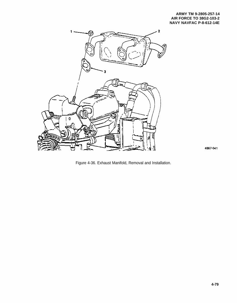
ARMY TM 9-2805-257-14AIR FORCE TO 38G2-103-2
NAVY NAVFAC P-8-612-14E
Figure 4-36. Exhaust Manifold, Removal and Installation.
4-79
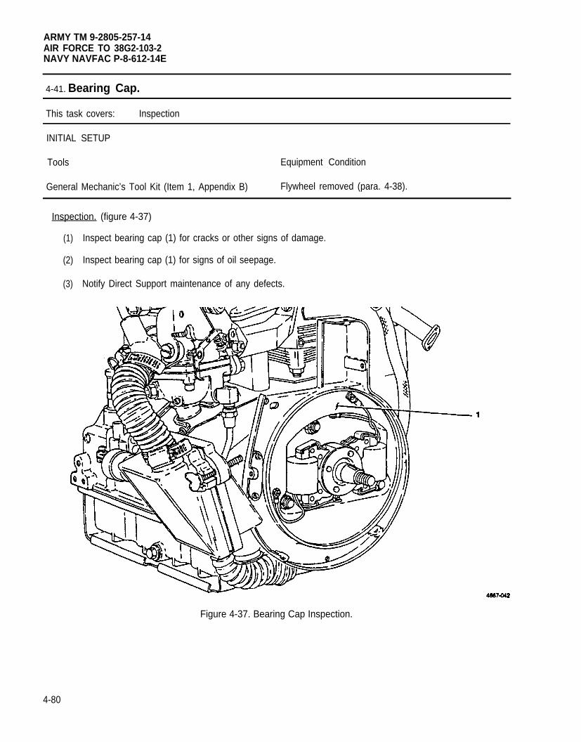
ARMY TM 9-2805-257-14AIR FORCE TO 38G2-103-2NAVY NAVFAC P-8-612-14E
4-41. Bearing Cap.
This task covers: Inspection
INITIAL SETUP
Tools Equipment Condition
General Mechanic’s Tool Kit (Item 1, Appendix B) Flywheel removed (para. 4-38).
Inspection. (figure 4-37)
(1)
(2)
(3)
Inspect bearing cap (1) for cracks or other signs of damage.
Inspect bearing cap (1) for signs of oil seepage.
Notify Direct Support maintenance of any defects.
Figure 4-37. Bearing Cap Inspection.
4-80
ARMY TM 9-2805-257-14AIR FORCE TO 38G2-103-2
NAVY NAVFAC P-8-612-14E
Section VI. PREPARATION FOR SHIPMENT OR STORAGE
Paragraph Page
4-42 General . . . . . . . . . . . . . . . . . . . . . . . . . . . . . . . . . . . . . . . . . . . . . . . . . . . . . . . . . . . . ...4-814-43 Short Term and Intermediate Storage Procedures . . . . . . . . . . . . . . . . . . . . . . . . . . . . . . 4-814-44 Administrative Storage . . . . . . . . . . . . . . . . . . . . . . . . . . . . . . . . . . . . . . . . . . . . . . . . . ...4-81
4-42. General. This section contains procedures to place the engine into either short term or intermediatestorage.
4-43.
a.
b.
c.
d.
e.
4-44.
a.
b.
c.
NOTE
The procedures for placing the engine into either short term or intermediate storage arethe same.
Short Term and Intermediate Storage Procedures.
Perform operator Before and After and Unit PMCS.
Remove end item fuel supply.
Drain fuel system.
Drain engine oil.
Secure fuel filter and starter rope to engine.
Administrative Storage.
Placement of equipment in administrative storage should be for short periods of time when a shortage ofmaintenance effort exists. Items should be in mission readiness within 24 hours or within the time factorsdetermined by the directing authority. During the storage period appropriate maintenance records will bekept.
Before placing equipment in administrative storage, current maintenance services and equipmentserviceable criteria (ESC) evaluations should be corrected, and all modification work orders (MWO’S) shouldbe applied.
Storage site selection. Inside storage is preferred for items selected for administrative storage. If insidestorage is not available, trucks, vans, conex containers and other containers may be used.
4-81/(4-82 blank)

ARMY TM 9-2805-257-14AIR FORCE TO 38G2-103-2
NAVY NAVFAC P-8-612-14E
CHAPTER 5
DIRECT SUPPORT MAINTENANCE INSTRUCTIONS
Page
OVERVIEW . . . . . . . . . . . . . . . . . . . . . . . . . . . . . . . . . . . . . . . . . . . . . . . . . . . . . . . . . . . . . . . ...5-1Section l. Repair Parts; Special Tools; Test, Measurement, Diagnostic
Equipment (TMDE); and Support Equipment . . . . . . . . . . . . . . . . . . . . . . . . . . . . . . 5-1Section Il. Direct Support Troubleshooting.. . . . . . . . . . . . . . . . . . . . . . . . . . . . . . . . . . . . . ...5-2Section lll. Direct Support Maintenance Procedures . . . . . . . . . . . . . . . . . . . . . . . . . . . . . . . ...5-5
OVERVIEW
This chapter contains information for troubleshooting and maintenance of the engine by Direct SupportMaintenance personnel.
Section I. REPAIR PARTS; SPECIAL TOOLS; TEST, MEASUREMENT,DIAGNOSTIC EQUIPMENT (TMDE); AND SUPPORT EQUIPMENT
Paragraph Page
5-1 Common Tools and Test Equipment . . . . . . . . . . . . . . . . . . . . . . . . . . . . . . . . . . . . . . ...5-15-2 Special Tools, TMDE, and Support Equipment . . . . . . . . . . . . . . . . . . . . . . . . . . . . . . . . . 5-15-3 Repair Parts . . . . . . . . . . . . . . . . . . . . . . . . . . . . . . . . . . . . . . . . . . . . . . . . . . . . . . . . . ...5-1
5-1. Common Tools and Equipment. For authorized common tools and equipment, refer to the ModifiedTable of Organization and Equipment (MTOE) applicable to your unit.
5-2. Special Tools, TMDE and Support Equipment. For a listing of special tools, TMDE, and supportequipment authorized for use on this equipment, refer to the Repair Parts and Special Tools List, TM 5-2805-257-24P, and the maintenance allocation chart (MAC), appendix B of this manual.
5-3. Repair Parts. Repair parts are listed and illustrated in the Repair Parts and Special Tools List for 3 HPMilitary Standard Engine, TM 5-2805-257-24P.
Section Il. DIRECT SUPPORT TROUBLESHOOTING
Paragraph Page
5-4 General . . . . . . . . . . . . . . . . . . . . . . . . . . . . . . . . . . . . . . . . . . . . . . . . . . . . . . . . . . . . ..5-15-5 Direct Support Troubleshooting Procedures . . . . . . . . . . . . . . . . . . . . . . . . . . . . . . . . ...5-2
5-4. General. This section contains troubleshooting procedures to determine the probable cause of observedequipment malfunctions. Test or inspections are provided to isolate the faulty component and corrective actionsare provided to eliminate the malfunction.
5-1
RMY TM 9-2805-257-14AIR FORCE TO 38G2-103-2NAVY NAVFAC P-8-612-14E
5-5. Direct Support Troubleshooting Procedures. Table 5-1 lists the common malfunctions that maybe found during operation. Refer to symptom index to locate the troubleshooting procedures for the malfunction.This manual cannot list all malfunctions that may occur, nor all test or inspections and corrective actions. If amalfunction is not corrected by listed corrective actions, notify your supervisor.
SYMP TOM INDEX
PageSymptom
Engine will not start . . . . . . . . . . . . . . . . . . . . . . . . . . . . . . . . . . . . . . . . . . . . . . . . . . . . . . . . . . . . . . . . . . . . . . . . . . . . . . . . . . .. . . . . . . . . . . . . . . 5-2Engine misses or runs erratically . . . . . . . . . . . . . . . . . . . . . . . . . . . . . . . . . . . . . . . . . . . . . . . . . . . . ...5-2Engine oil consumption excessive . . . . . . . . . . . . . . . . . . . . . . . . . . . . . . . . . . . . . . . . . . . . . . . . . . . ...5-3Engine runs excessively noisy . . . . . . . . . . . . . . . . . . . . . . . . . . . . . . . . . . . . . . . . . . . . . . . . . . . . . . ...5-3Engine will not start or runs erratically . . . . . . . . . . . . . . . . . . . . . . . . . . . . . . . . . . . . . . . . . . . . . . . . ...5-4
Table 5-1. Direct Support Troubleshooting Procedures.
MalfunctionTest or Inspection
Corrective Action
1. ENGINE FAILS TO START.
Step 1. Inspect and test coils. Measure resistance of primary and secondary windings. Measurementsshould be as follows for breaker point coil:
Coil type Primary windings Secondary windings
Bendix Corp. .512 ± .050 ohms 3,300 ± 400 ohmsColt Industries .370 ± .025 ohms 8,500 ± 700 ohmsMotor Parts. Inc. .370 ± .025 ohms 8,500 ± 700 ohms
Step 2. Inspect rotating magnet for corrosion.
Replace rotating magnet if corroded or otherwise damaged (para. 5-19).
2. ENGINE MISSES OR RUNS ERRATICALLY.
Step 1. Check ignition timing (para. 5-9).
Adjust ignition timing (para 5-9).
5-2
ARMY TM 9-2805-257-14AIR FORCE TO 38G2-103-2
NAVY NAVFAC P-8-612-14E
Table 5-1. Direct Support Troubleshooting Procedures (cont).
MalfunctionTest or Inspection
Corrective Action
Step 2. Check valve adjustment.
Adjust valves as needed (para. 5-16).
Step 3. Inspect and test coil (para. 5-20).
Replace defective coil (para. 5-20).
Step 4. Check for cracked cylinder head and or leaky gasket.
Replace cracked or otherwise damaged cylinder head (para. 5-14).
Step 5. Check intake and exhaust valve for damage or excessive wear.
Replace damaged valve (para. 5-17).
Step 6. Check piston and piston rings for damage or excessive wear.
Replace damaged or worn piston or rings (para. 5-18).
3. ENGINE OIL CONSUMPTION EXCESSIVE.
Step 1. Check crankshaft side oil seal for seepage or leakage.
Replace faulty crankshaft side oil seal (para 5-23).
Step 2. Check flywheel side oil seal for seepage or leakage.
Replace faulty flywheel side oil seal (para 5-21).
Step 3. Check piston and piston rings for wear.
Replace worn or damaged piston and pinton rings (para. 5-18).
4. ENGINE RUNS EXCESSIVELY NOISY.
Step 1. Cheek valve mechanism for bent or otherwise damaged components.
Replace worn or damaged components (para 5-14).
Step 2. Check piston and connecting rod for wear.
Replace worn piston or connecting rod (para 5-18).
5-3
ARMY TM 9-2805-257-14AIR FORCE TO 38G2-103-2NAVY NAVFAC P-8-612-14E
Table 5-1. Direct Support Troubleshooting Procedures (cont).
MalfunctionTest or Inspection
Corrective Action
5. ENGINE WILL NOT START OR RUNS ERRATICALLY MODEL 2A016-4.
NOTE
The following procedures can be performed with either a digital or analog multimeterrefer to figure 5-26 for wiring diagram of electronic ignition system.
Step 1. Check low and high voltage cable ends for looseness.
Tighten any loose connections.
NOTE
There are two high voltage cables, repeat step for both cables.
Step 2. Remove high voltage cable from spark plug. Ground cable and hold spring approximately1/4 in. (6 cm.) from engine. Pull start engine and check for spark.
If spark is present remove and inspect spark plug (para. 4-19).
Step 3. Remove ignition control unit cover and check for moisture or foreign material.
If moisture is present clean and dry terminals and connections and repeat step 2.
Step 4. Check low voltage cable end to end continuity.
If continuity is not present in all three lines replace low voltage cable (para. 5-13).
Step 5. Remove wiring from no. 1 terminal on ignition control unit module. Measure resistancebetween terminal no. 1 and ground.
If reading is less than 1 Megohm replace ignition module (para. 5-12).
Step 6. Remove wiring from terminals no. 5 and no. 6 and check resistance. Meter should show aninitial deflection then a reading of 1 Megohm.
If final reading is not 1 Megohm then replace ignition control unit ignition module(para. 5-12).
NOTE
There are two transformers in the ignition control unit, repeat steps 7 and 8 for bothtransformers.
5-4
ARMY TM 9-2805-257-14AIR FORCE TO 38G2-103-2
NAVY NAVFAC P-8-612-14E
Table 5-1. Direct Support Troubleshooting Procedures (cont).
MalfunctionTest or Inspection
Corrective Action
Step 7. Check transformer resistance between white and brown wires.
If resistance is more than 1 ohm replace transformer (para. 5-11).
Step 8. Check transformer resistance between white wire and spring on end of high voltage cable.
If resistance is not between 1400 and 2500 ohms, replace transformer (para. 5-11).
Step 9. Check coil resistance between pins A and B of low voltage connector on engine.
If resistance is not between 289 and 329 ohms replace coil (para. 5-20).
Paragraph
5-65-75-85-95-105-115-125-135-145-155-165-175-185-195-205-215-225-235-24
Section Ill. DIRECT SUPPORT MAINTENANCE PROCEDURE
Page
General . . . . . . . . . . . . . . . . . . . . . . . . . . . . . . . . . . . . . . . . . . . . . . . . . . . . . . . . . . . . ...5-5Oil Pan . . . . . . . . . . . . . . . . . . . . . . . . . . . . . . . . . . . . . . . . . . . . . . . . . . . . . . . . . . . . . ...5-6Governor Assembly . . . . . . . . . . . . . . . . . . . . . . . . . . . . . . . . . . . . . . . . . . . . . . . . . . . ...5-8Ignition Timing (Breaker Point Ignition). . . . . . . . . . . . . . . . . . . . . . . . . . . . . . . . . . . . ...5-16Ignition Control Unit (Breakerless Ignition) . . . . . . . . . . . . . . . . . . . . . . . . . . . . . . . . . ...5-18Transformer (Breakerless Ignition) . . . . . . . . . . . . . . . . . . . . . . . . . . . . . . . . . . . . . . . ...5-20Ignition Module (Breakerless Ignition).. . . . . . . . . . . . . . . . . . . . . . . . . . . . . . . . . . . . ...5-22Low Voltage Cable (Breakerless Ignition) . . . . . . . . . . . . . . . . . . . . . . . . . . . . . . . . . . ...5-24Cylinder Head . . . . . . . . . . . . . . . . . . . . . . . . . . . . . . . . . . . . . . . . . . . . . . . . . . . . . . . . . . 5-26Rockers . . . . . . . . . . . . . . . . . . . . . . . . . . . . . . . . . . . . . . . . . . . . . . . . . . . . . . . . . . . . ...5-32Valve Adjustment . . . . . . . . . . . . . . . . . . . . . . . . . . . . . . . . . . . . . . . . . . . . . . . . . . . . . ...5-34lntake and Exhaust Valves . . . . . . . . . . . . . . . . . . . . . . . . . . . . . . . . . . . . . . . . . . . . . ...5-36Piston and Connection Rod Assembly . . . . . . . . . . . . . . . . . . . . . . . . . . . . . . . . . . . . . ...5-38Rotating Magnet . . . . . . . . . . . . . . . . . . . . . . . . . . . . . . . . . . . . . . . . . . . . . . . . . . . . . ...5-44Coil . . . . . . . . . . . . . . . . . . . . . . . . . . . . . . . . . . . . . . . . . . . . . . . . . . . . . . . . . . . . . . . . ...5-46Flywheel Side Oil Seal. . . . . . . . . . . . . . . . . . . . . . . . . . . . . . . . . . . . . . . . . . . . . . . ...5-48Noise Suppression Filter (Breaker Point Ignition) . . . . . . . . . . . . . . . . . . . . . . . . . . . . . . . 5-50Crankshaft Side Oil Seal . . . . . . . . . . . . . . . . . . . . . . . . . . . . . . . . . . . . . . . . . . . . . . . ...5-52Compression Test . . . . . . . . . . . . . . . . . . . . . . . . . . . . . . . . . . . . . . . . . . . . . . . . . . . . ...5-54
5-6. General. This section contains direct support maintenance procedures as authorized by the MAC inAppendix B of this manual. Table 5-2 located at the end of this section contains a list of engine components andtheir wear limits. Any item that does not meet the specified measurements must be replaced. Refer to AppendixE for torque values. All maintenance procedures require only one person to perform.
5-5
ARMY TM 9-2805-257-14AIR FORCE TO 38G2-103-2NAVY NAVFAC P-8-612-14E
5-7. Oil Pan.
This task covers: a. Removal b. Installation
INITIAL SETUP
Tools Materials/Parts
General Mechanic’s Tool Kit (Item 1, Appendix B) Rags, Wiping (Item 6, Appendix D)Wrench, Torque (NSN 5120-00-230-6380) (Item 3, Solvent, Drycleaning (Item 7, Appendix D)
Appendix B) Gasket, Oil Pan Mounting (NSN 5330-00-797-3515)
a. Removal. (figure 5-1)
(1)
(2)
(3)
(4)
(5)
(6)
(7)
Remove either drain plug (1) or (2) and drain oil into suitable container.
Remove lower air duct and upper air duct (para. 4-16).
Remove twelve screws (3) and washers (4) and remove oil pan (5) and gasket (6).
WARNING
Dry cleaning solvent PD-680 used to clean parts is potentially dangerous to personneland property. Avoid repeated and prolonged skin contact. Do not use near open flameor excessive heat. Flash point of solvent is 100°F -138°F (38°C-60°C).
Clean oil pan (5) and drain plug (1) or (2) with dry cleaning solvent and dry thoroughly.
Inspect oil pan and drain plugs for signs of damage. Replace as needed.
Replace washer (7) on drain plug (1) or (2).
Clean gasket surfaces and remove old gasket material.
b. Intallation. (figure 5-1)
(1) Install oil pan (5) and gasket (6) and secure with twelve screws (3) and washers (4). Torque screws to25-30 in. Ibs. (4465-5358 gr. cm.).
(2) Install drain plug (1) or (2) with washer (7).
(3) Install lower air duct and upper air duct (para. 4-16).
(4) Refill engine oil (refer to LO 9-2805-257-14 for proper grade of oil).
5-6
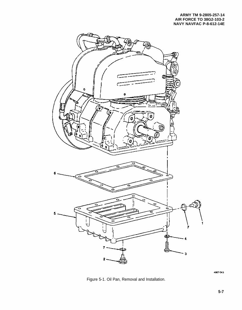
ARMY TM 9-2805-257-14AIR FORCE TO 38G2-103-2
NAVY NAVFAC P-8-612-14E
Figure 5-1. Oil Pan, Removal and Installation.
5-7
ARMY TM 9-2805-257-14AIR FORCE TO 38G2-103-2NAVY NAVFAC P-8-612-14E
5-8. Governor Assembly.
This task covers: a. Removal c. Repair (breaker point ignition)b. Repair (breakerless ignition) d. Installation
INITIAL SETUP
Tools Materials/Parts (cont)
General Mechanic’s Tool Kit (Item 1, Appendix B) Gasket, Throttle Housing to Carburetor(P/N 9786E65-4)
Materials/Parts Gasket, Throttle Housing Front (P/N 9786E64-6)Gasket, Throttle Housing Rear (P/N 9786E65-3)
Rags, Wiping (Item 6, Appendix D)Solvent, Drycleaning (Item 7, Appendix D)
a. Removal. (figure 5-2)
(1)
(2)
(3)
(4)
(5)
(6)
(7)
5-8
Loosen clamp (1) and remove control rod housing (2) from throttle housing (3).
Remove two screws (4) and washers (5) securing throttle housing cover (6) and gasket (7) and remove.
Remove screw (8) and washer (9) securing throttle lever (10) to throttle rod (11) and remove.
Remove two screws (12) and washers (13) and remove throttle housing (3) gasket (14) rear cover (15)and gasket (16).
NOTE
On engines with breaker point ignitions make note of grounding strap placement beforeremoving screws securing governor assembly.
Tag and remove condenser leads (17) and (18) from noise suppression filters (19) and (20).
Remove three screws (21) and washers (22) securing governor assembly (23) and gasket (24) andremove.
Remove old gasket from mating surfaces.
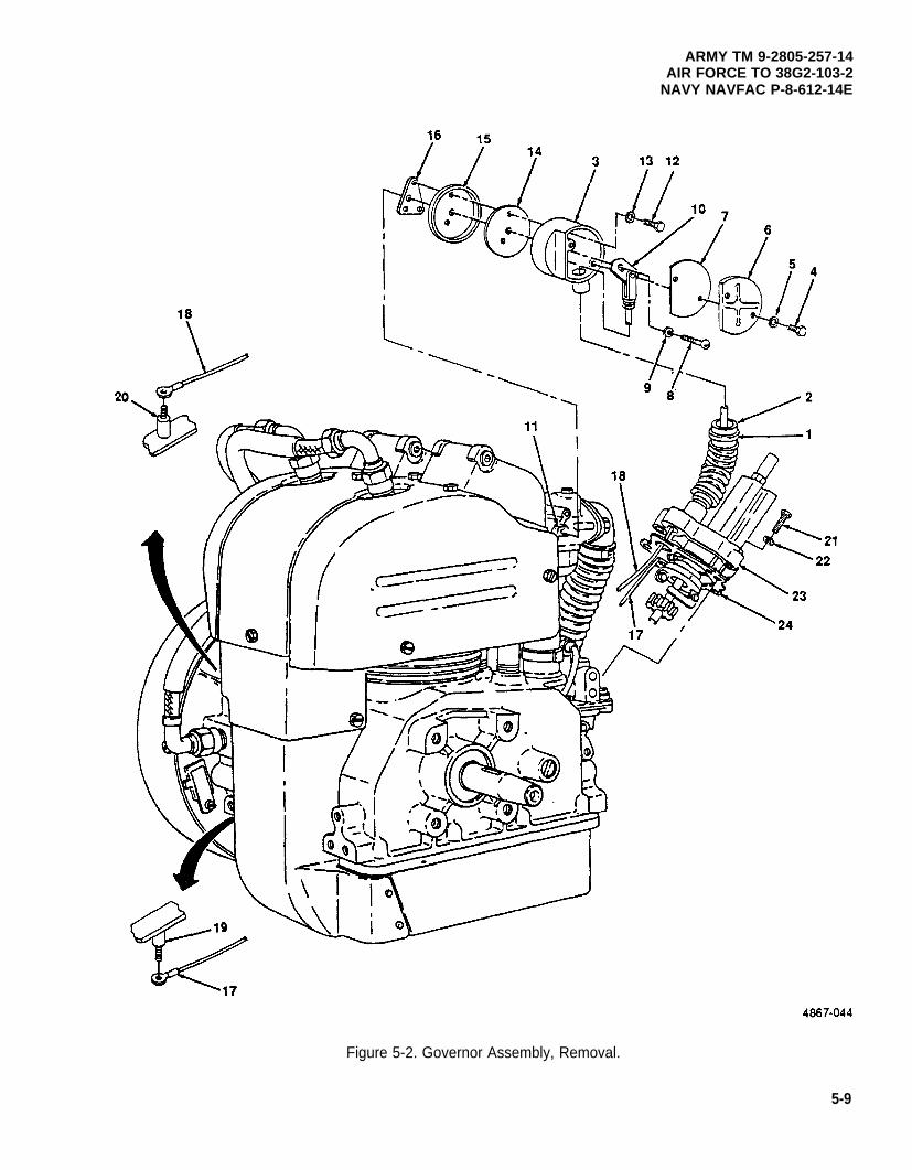
ARMY TM 9-2805-257-14AIR FORCE TO 38G2-103-2
NAVY NAVFAC P-8-612-14E
Figure 5-2. Governor Assembly, Removal.
5-9
ARMY TM 9-2805-257-14AIR FORCE TO 38G2-103-2NAVY NAVFAC P-8-612-14E
5-8. Governor Assembly (cont).
b. Repair Breakerl ess Ignition. (figure 5-3)
(1)
(2)
(3)
(4)
5-10
Using suitable punch, remove pin (1) and remove flyweight and carrier assembly (2) from shaft (3).
WARNING
Dry cleaning solvent PD-680 used to clean parts is potentially dangerous to personneland property. Avoid repeated and prolonged skin contact. Do not use near open flameor excessive heat. Flash point of solvent is 100°F–138°F (38°C-60°C).
Clean flyweight and carrier assembly (2) with drycleaning solvent and dry thoroughly.
Inspect flyweight and carrier assembly (2) for wear and replace if worn or otherwise damaged.
Install flyweight and carrier assembly (2) on shaft (3) and secure with pin (1).
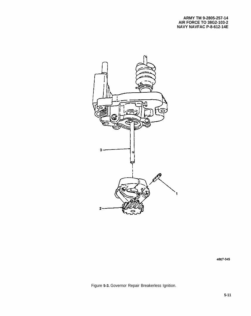
ARMY TM 9-2805-257-14AIR FORCE TO 38G2-103-2
NAVY NAVFAC P-8-612-14E
Figure 5-3. Governor Repair Breakerless Ignition.
5-11
ARMY TM 9-2805-257-14AIR FORCE TO 38G2-103-2NAVY NAVFAC P-8-612-14E
5-8. Governor Assembly (cont).
c. Repair. Breaker Point Ignition. (figure 5-4)
(1) Using suitable punch, remove pin (1) and remove flyweight and carrier assembly (2) from shaft (3).
WARNING
Dry cleaning solvent PD-680 used to clean parts is potentially dangerous to personneland property. Avoid repeated and prolonged skin contact. Do not use near open flameor excessive heat. Flash point of solvent is 100°F -138°F (38°C-60°C).
(2) Clean flyweight and carrier assembly (2) with drycleaning solvent and dry thoroughly.
(3) Inspect flyweight and carrier assembly (2) for wear and replace if worn or otherwise damaged.
(4) Install flyweight and carrier assembly (2) on shaft (3) and secure with pin (1).
5-12
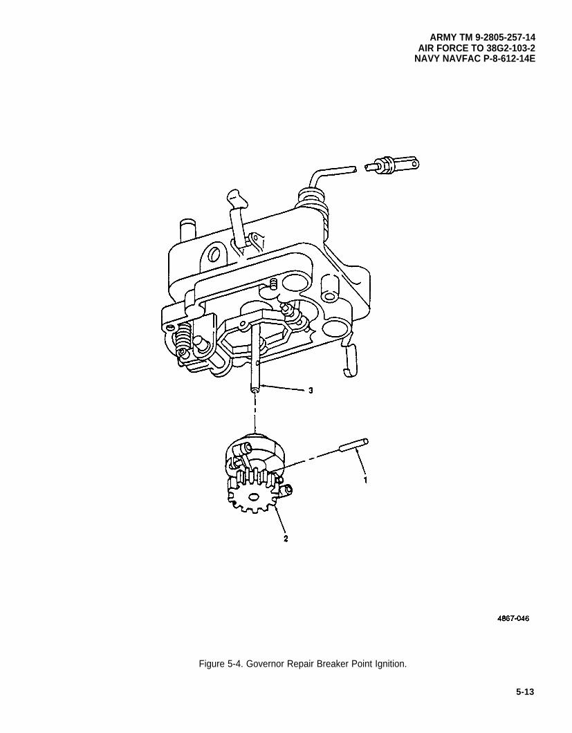
ARMY TM 9-2805-257-14AIR FORCE TO 38G2-103-2
NAVY NAVFAC P-8-612-14E
5-13
Figure 5-4. Governor Repair Breaker Point Ignition.
ARMY TM 9-2805-257-14AIR FORCE TO 38G2-103-2NAVY NAVFAC P-8-612-14E
5-8. Governor Assembly (cont).
d. Installation. (figure 5-5)
(1)
(2)
(3)
(4)
(5)
(6)
5-14
NOTE
On engines with breaker point ignitions install grounding strap at lower left of governorassembly.
Install governor assembly (23) and gasket (24) and secure with three screws (21) and washers (22).
Connect condenser leads (17) and (18) to noise suppression filters (19) and (20) and remove tags.
Install gasket (16), rear cover (15), gasket (14), and throttle housing (3) and secure with two screws (12)and washers (13).
Position throttle lever (10) on throttle rod (11) and secure with screw (8) and washer (9).
Install throttle housing cover (6) and gasket (7) and secure with two screws (4) and washers (5).
Install control rod housing (2) on throttle housing (3) and secure with clamp (1).
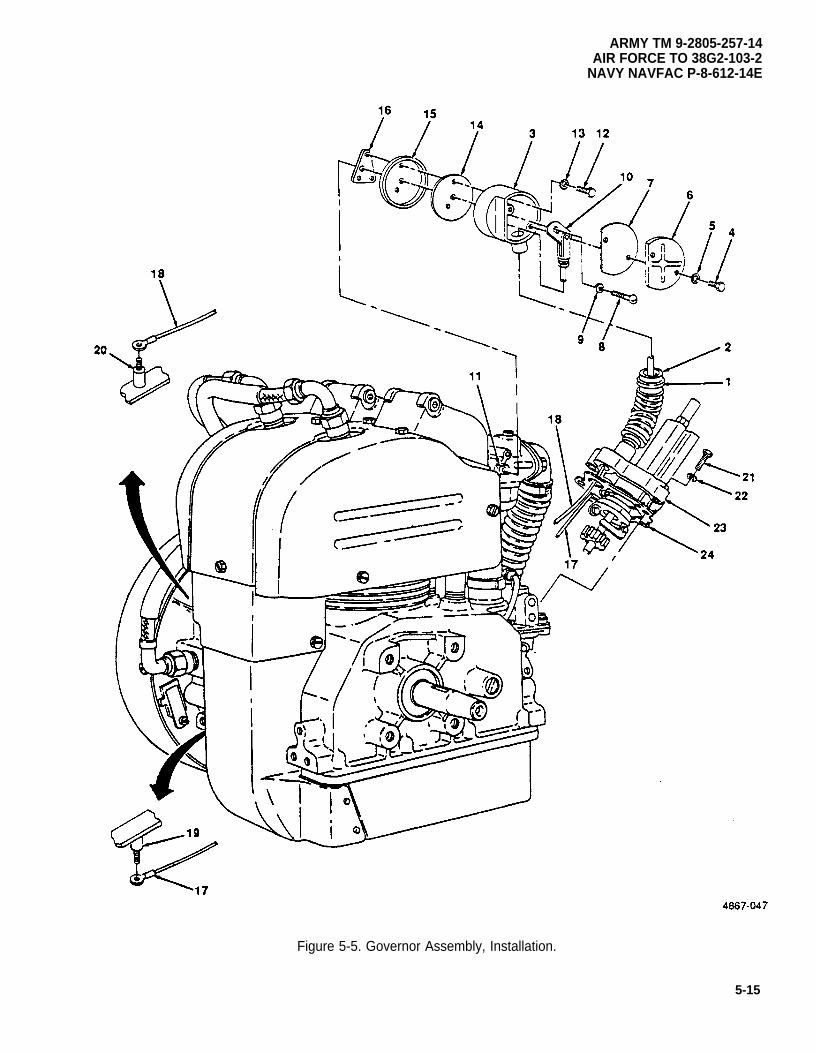
Figure 5-5. Governor Assembly, Installation.
ARMY TM 9-2805-257-14AIR FORCE TO 38G2-103-2
NAVY NAVFAC P-8-612-14E
5-15
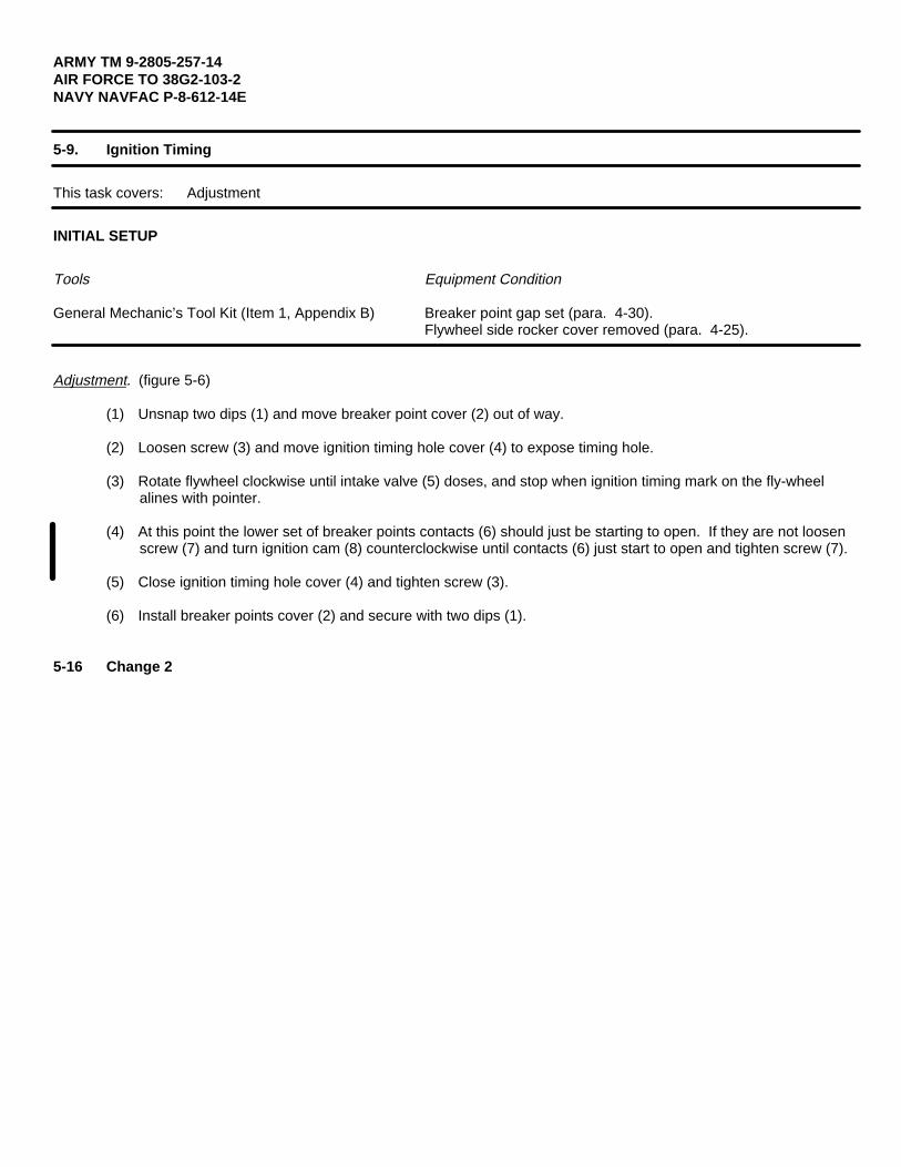
ARMY TM 9-2805-257-14AIR FORCE TO 38G2-103-2NAVY NAVFAC P-8-612-14E
5-9. Ignition Timing
This task covers: Adjustment
INITIAL SETUP
Tools Equipment Condition
General Mechanic’s Tool Kit (Item 1, Appendix B) Breaker point gap set (para. 4-30).Flywheel side rocker cover removed (para. 4-25).
Adjustment. (figure 5-6)
(1) Unsnap two dips (1) and move breaker point cover (2) out of way.
(2) Loosen screw (3) and move ignition timing hole cover (4) to expose timing hole.
(3) Rotate flywheel clockwise until intake valve (5) doses, and stop when ignition timing mark on the fly-wheelalines with pointer.
(4) At this point the lower set of breaker points contacts (6) should just be starting to open. If they are not loosenscrew (7) and turn ignition cam (8) counterclockwise until contacts (6) just start to open and tighten screw (7).
(5) Close ignition timing hole cover (4) and tighten screw (3).
(6) Install breaker points cover (2) and secure with two dips (1).
5-16 Change 2
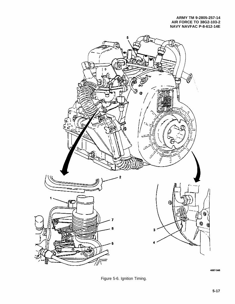
ARMY TM 9-2805-257-14AIR FORCE TO 38G2-103-2
NAVY NAVFAC P-8-612-14E
Figure 5-6. Ignition Timing.
5-17
ARMY TM 9-2805-257-14AIR FORCE TO 38G2-103-2NAVY NAVFAC P-8-612-14E
5-10. Ignition Control Unit (Breakerless Ignition).
This task covers: a. Removal b. Installation
INITIAL SETUP
Tools
General Mechanic’s Tool Kit (Item 1, Appendix B)
a. Removal. (figure 5-7)
(1) Disconnect low voltage cable (1) from ignition control unit (2).
(2) Loosen connector nut (3) and remove high tension cable (4) from ignition control unit (2).
(3) Loosen connector nut (5) and remove high tension cable (6) from ignition control unit (2).
(4) Remove two screws (7) and washers (8) and remove ignition control unit (2).
b. Installation. (figure 5-7)
(1)
(2)
(3)
(4)
5-18
Install ignition control unit (2) and secure with two screws (7) and two washers (8).
Connect low voltage cable (1) to ignition control unit (2).
Install high tension cable (4), and tighten connector nut (3).
Install high tension cable (6), and tighten connector nut (5).
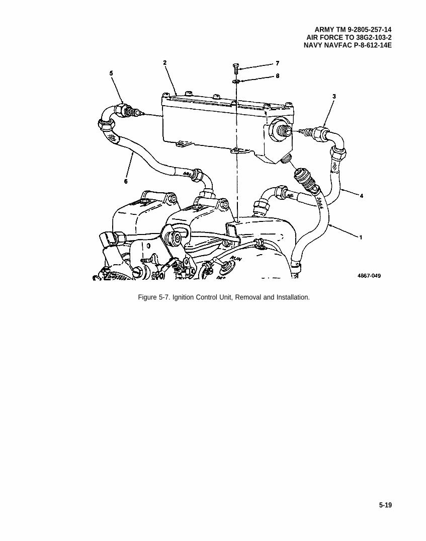
ARMY TM 9-2805-257-14AIR FORCE TO 38G2-103-2
NAVY NAVFAC P-8-612-14E
Figure 5-7. Ignition Control Unit, Removal and Installation.
5-19
ARMY TM 9-2805-257-14AIR FORCE TO 38G2-103-2NAVY NAVFAC P-8-612-14E
5-11. Transformer (Breakerless Ignition).
This task covers: a. Removal b. Installation
INITIAL SETUP
Tools
General Mechanic’s Tool Kit (Item 1, Appendix B)
NOTE
This engine is equipped with two transformers, the removal and installation proceduresare the same for both.
a. Removal. (figure 5-8)
(1)
(2)
(3)
(4)
(5)
Remove six screws (1) and remove cover (2).
Tag and remove transformer leads from ignition control unit (3).
Loosen connector nut (4) and remove ignition cable (5) from ignition control unit (3)
Remove nut (6) and remove transformer (7) and O ring (8).
Inspect O ring (8) and replace if ripped or otherwise damaged.
b. Installation. (figure 5-8)
(1) Install transformer (7) and O ring (8) and secure with nut (6).
(2) Connect transformer leads as tagged.
(3) Install cover (2) and secure with six screws (1).
(4) Install ignition cable (5) and tighten connector nut (4).
5-20
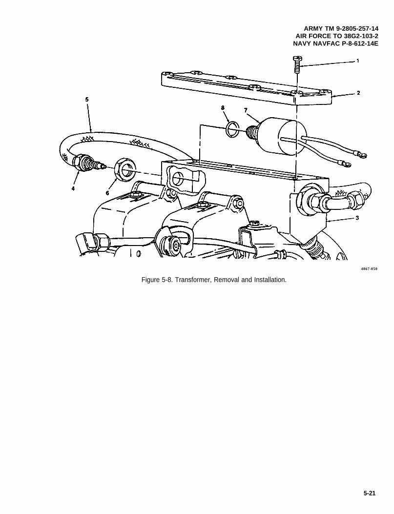
ARMY TM 9-2805-257-14AIR FORCE TO 38G2-103-2
NAVY NAVFAC P-8-612-14E
4867-050
Figure 5-8. Transformer, Removal and Installation.
5-21
ARMY TM 9-2805-257-14AIR FORCE TO 38G2-103-2NAVY NAVFAC P-8-612-14E
5-12. Ignition Module (Breakerless Ignition).
This task covers: a. Removal b. Installation
INITIAL SETUP
Tools
General Mechanic’s Tool Kit (Item 1, Appendix B)
a. Removal. (figure 5-9)
(1)
(2)
(3)
(4)
Remove six screws (1) and remove cover (2).
Tag and remove wiring from terminals on ignition module (3).
Tag wiring secured by ignition module mounting hardware.
Remove two screws (4) and washers (5) and remove ignition module (3).
b. Installation . (figure 5-9)
NOTE
Install wiring as tagged to ignition module mounting screws before installing screws.
(1) Install ignition module (3) and secure with two screws (4) and washers (5).
(2) Connect wiring to ignition module terminals as tagged.
(3) Install cover (2) and secure with six screws (1).
5-22
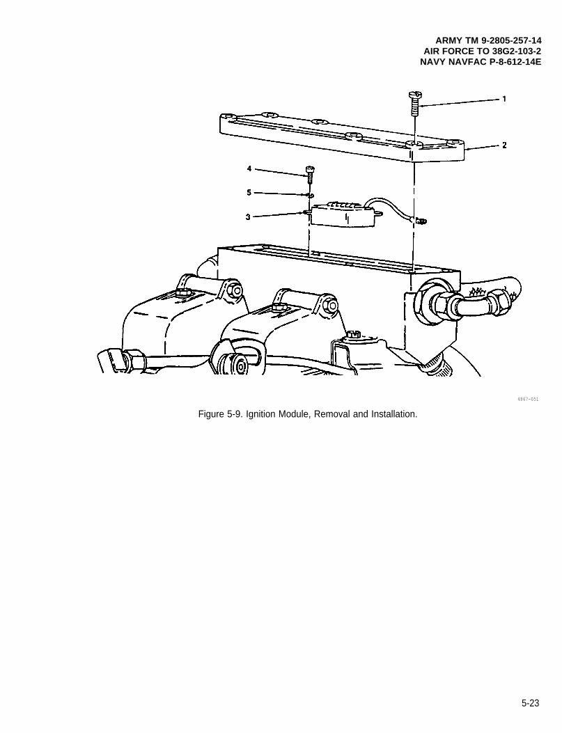
ARMY TM 9-2805-257-14AIR FORCE TO 38G2-103-2
NAVY NAVFAC P-8-612-14E
4867-051
Figure 5-9. Ignition Module, Removal and Installation.
5-23
ARMY TM 9-2805-257-14AIR FORCE TO 38G2-103-2NAVY NAVFAC P-8-612-14E
5-13. Low Voltage Cable (Breakerless Ignition).
This task covers: a. Removal b. Installation
INITIAL SETUP
Tools Equipment Condition
General Mechanic’s Tool Kit (Item 1, Appendix B) Flywheel Removed (para. 4-38)
a. Removal. (figure 5-10)
WARNING
Use extreme care when removing coil clamps. Flying clamps can cause serious eyeinjury. Cover work area with rag or hand when removing clamps.
NOTE
(1)
(2)
(3)
(4)
Before removing coil observe placement of coil leads.
Remove two coil clamps (1) and move coil (2) slightly, tag and disconnect coil leads and remove coil (2).
Disconnect low voltage cable (3) from ignition control unit (4).
Remove two clamps (5), cable nut (6) and washer (7) and pull low voltage cable lead (8) throughbearing cap (9).
Loosen connector nut (10) and remove low voltage cable (3).
b. Installation. (figure 5-10)
(1)
(2)
(3)
(4)
(5)
5-24
Install low voltage cable (3) and tighten connector nut (10).
Route low voltage cable lead (8) through bearing cap (9) and install washer (7) and cable nut (6) andtighten cable nut (6).
Install two clamps (5) on low voltage cable lead (8).
Connect low voltage cable (3) to ignition control unit (4).
Connect coil leads as tagged, and install coil (2) and secure with two coil clamps (1).
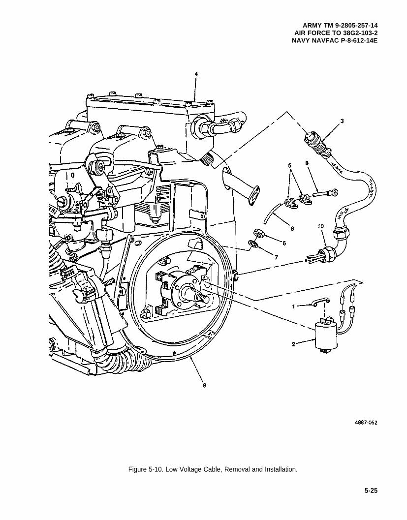
ARMY TM 9-2805-257-14AIR FORCE TO 38G2-103-2
NAVY NAVFAC P-8-612-14E
Figure 5-10. Low Voltage Cable, Removal and Installation.
5-25
ARMY TM 9-2805-257-14AIR FORCE TO 38G2-103-2NAVY NAVFAC P-8-612-14E
5-14. Cylinder Head.
This task covers: a. Removal b. Repair c. Installation
INITIAL SETUP
Tools
General Mechanic’s Tool Kit (Item 1, Appendix B)Wrench, Torque (NSN 5120-00-230-6380)
(Item 3, Appendix B)Compressor, Valve Spring (NSN 5330-00-096-6677)
(Item 3, Appendix B)
Materials/Parts
Rags, Wiping (Item 6, Appendix D)Solvent, Drycleaning (Item 7, Appendix D)
Materials/Parts (cont)
Gasket, Cylinder Head Mounting(NSN 5330-00-819-8734)Packing, Push Rod Housing (NSN 5330-00-797-3510)
Equipment Condition
Spark plugs removed (para. 4-19).Intake manifold removed (para. 4-39).Exhaust manifold removed (para. 4-40).Rocker cover removed (para. 4-25).Flywheel cover removed (para. 4-14).
NOTE
When removing cylinder heads, both heads must be removed at the same time.
a. Removal. (figure 5-11)
(1) Turn flywheel clockwise until both rockers (1), in cylinder heads (2) are closed.
(2) Remove eight nuts (3) and washers (4) and remove cylinder heads (2) and gaskets (5).
(3) Remove push rods (6), push rod housings (7), and preformed packings (8).
(4) Remove rear cylinder cover (9).
5-26
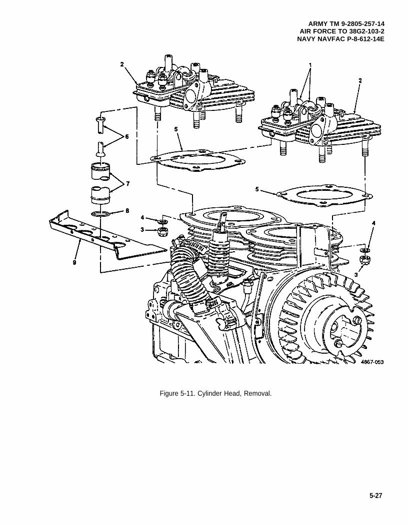
ARMY TM 9-2805-257-14AIR FORCE TO 38G2-103-2
NAVY NAVFAC P-8-612-14E
Figure 5-11. Cylinder Head, Removal.
5-27
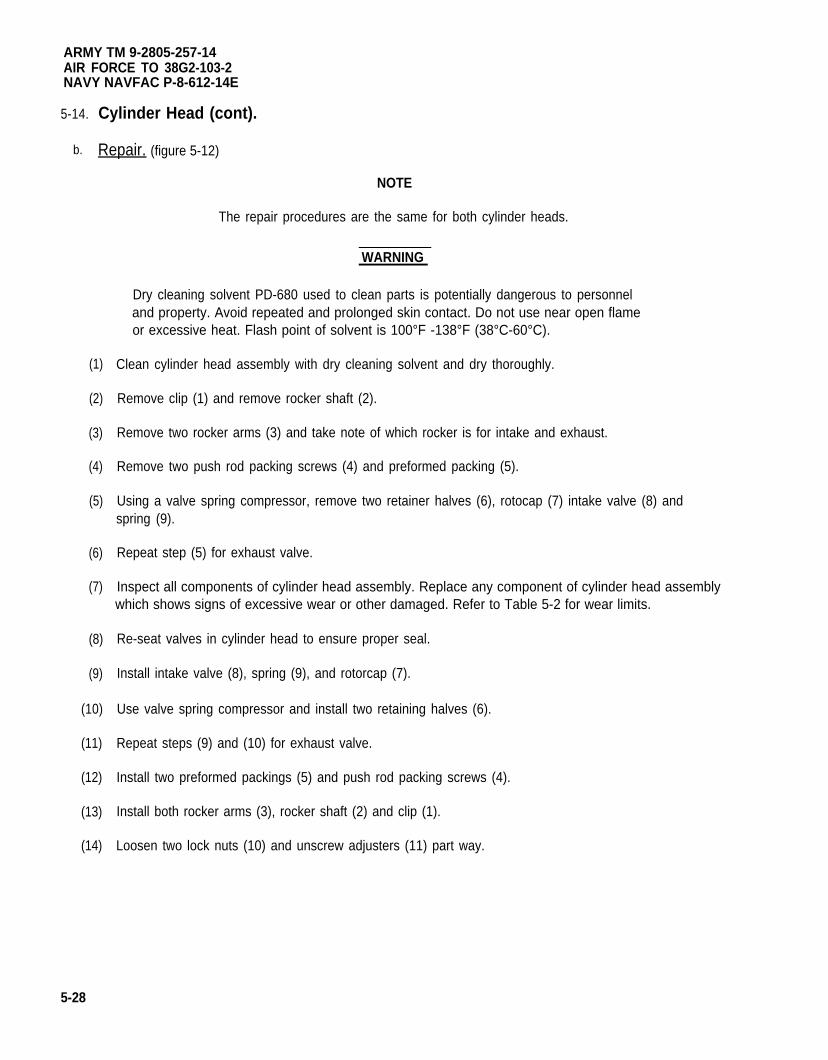
ARMY TM 9-2805-257-14AIR FORCE TO 38G2-103-2NAVY NAVFAC P-8-612-14E
5-14.
b.
(1)
(2)
(3)
(4)
(5)
(6)
(7)
(8)
(9)
(10)
(11)
(12)
(13)
(14)
5-28
Cylinder Head (cont).
Repair. (figure 5-12)
NOTE
The repair procedures are the same for both cylinder heads.
WARNING
Dry cleaning solvent PD-680 used to clean parts is potentially dangerous to personneland property. Avoid repeated and prolonged skin contact. Do not use near open flameor excessive heat. Flash point of solvent is 100°F -138°F (38°C-60°C).
Clean cylinder head assembly with dry cleaning solvent and dry thoroughly.
Remove clip (1) and remove rocker shaft (2).
Remove two rocker arms (3) and take note of which rocker is for intake and exhaust.
Remove two push rod packing screws (4) and preformed packing (5).
Using a valve spring compressor, remove two retainer halves (6), rotocap (7) intake valve (8) andspring (9).
Repeat step (5) for exhaust valve.
Inspect all components of cylinder head assembly. Replace any component of cylinder head assemblywhich shows signs of excessive wear or other damaged. Refer to Table 5-2 for wear limits.
Re-seat valves in cylinder head to ensure proper seal.
Install intake valve (8), spring (9), and rotorcap (7).
Use valve spring compressor and install two retaining halves (6).
Repeat steps (9) and (10) for exhaust valve.
Install two preformed packings (5) and push rod packing screws (4).
Install both rocker arms (3), rocker shaft (2) and clip (1).
Loosen two lock nuts (10) and unscrew adjusters (11) part way.
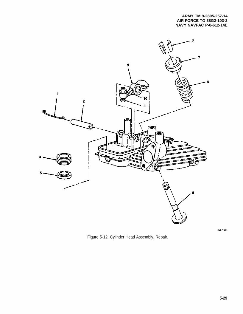
ARMY TM 9-2805-257-14AIR FORCE TO 38G2-103-2
NAVY NAVFAC P-8-612-14E
Figure 5-12. Cylinder Head Assembly, Repair.
5-29
ARMY TM 9-2805-257-14AIR FORCE TO 38G2-103-2NAVY NAVFAC P-8-612-14E
5-14. Cylinder Head (cont).
c. Installation. (figure 5-13)
(1) Install rear cylinder cover (9), four preformed packings (8), push rod housings (7) and push rods (6).
(2) Ensure cylinder head gasket mating surface is clean and all old gasket material is removed.
(3) Install cylinder heads (2) and new gaskets (5) and secure with eight nuts (3) and washers (4). Torquenuts to 140 to 155 in. Ibs (25000-27680 gr cm).
(4) Adjust valves (para. 5-16).
5-30
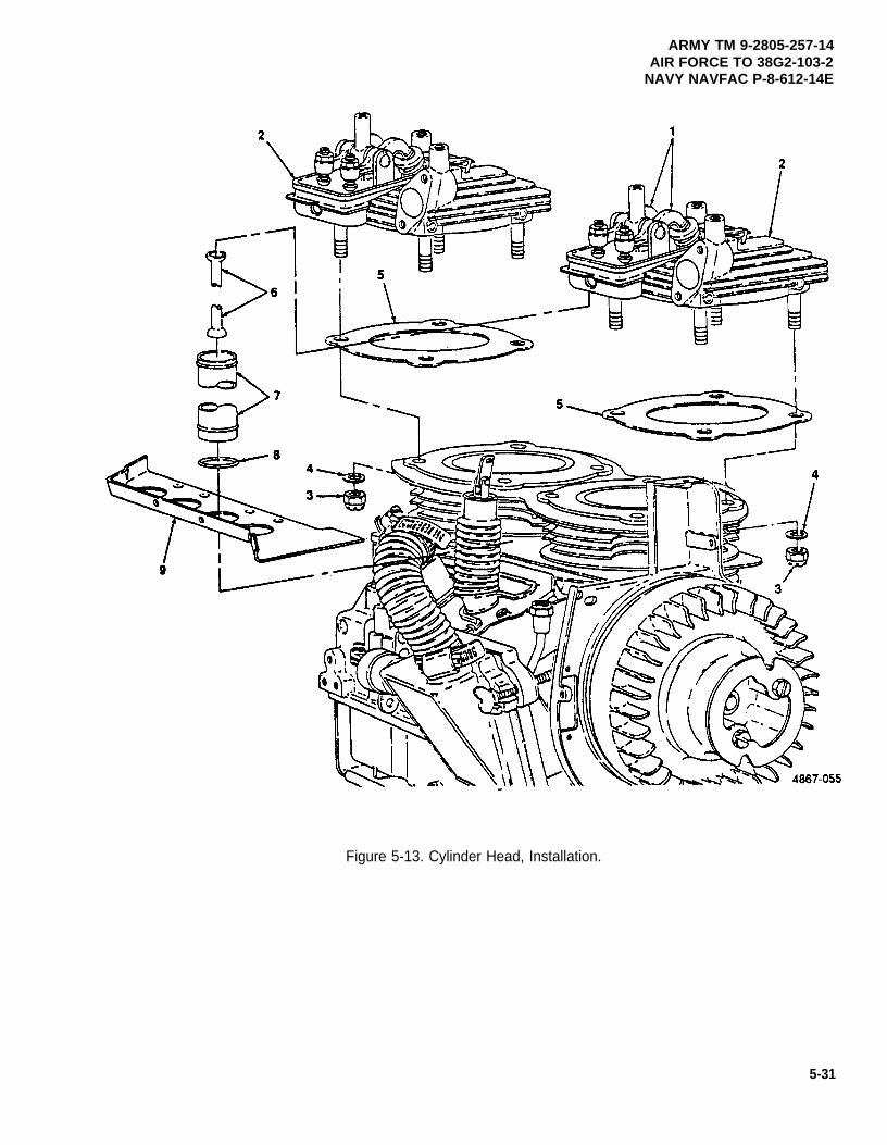
ARMY TM 9-2805-257-14AIR FORCE TO 38G2-103-2
NAVY NAVFAC P-8-612-14E
Figure 5-13. Cylinder Head, Installation.
5-31
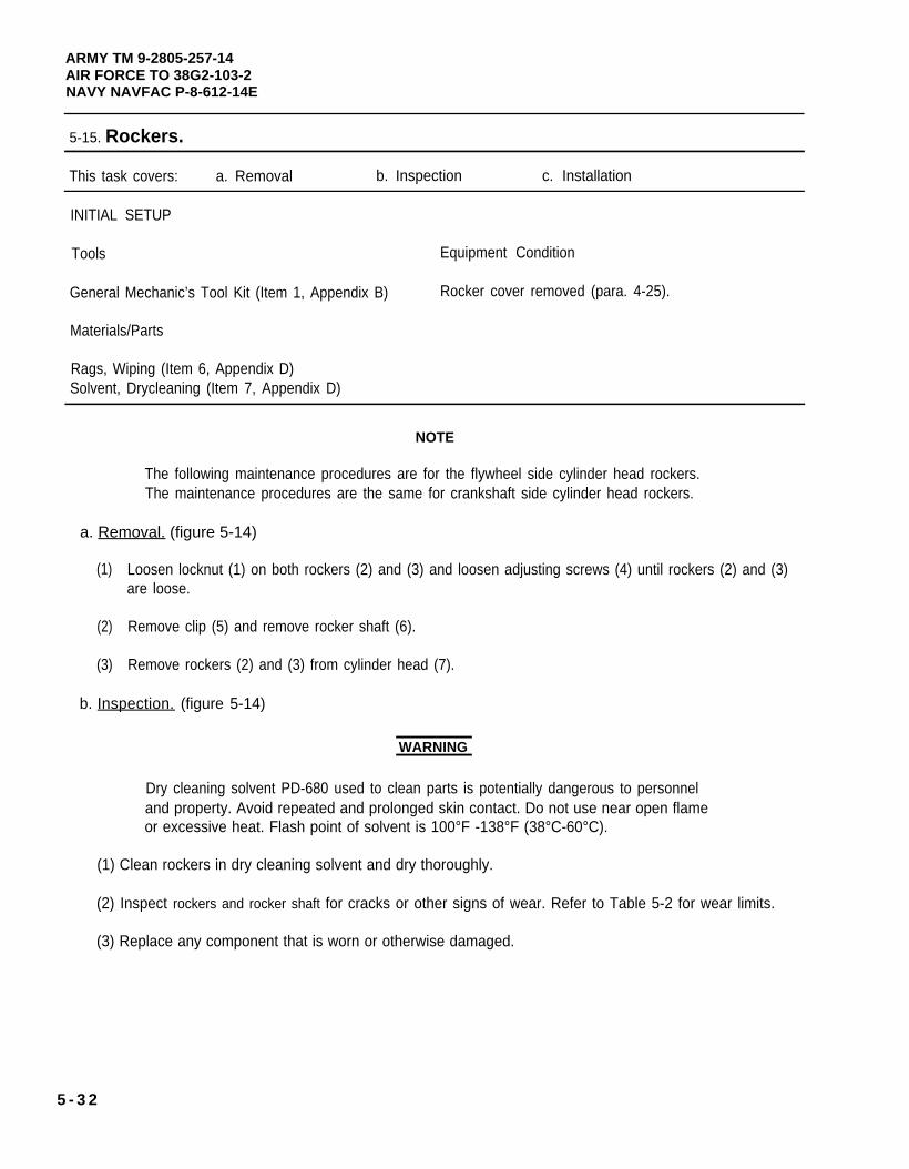
ARMY TM 9-2805-257-14AIR FORCE TO 38G2-103-2NAVY NAVFAC P-8-612-14E
5-15. Rockers.
This task covers: a. Removal b. Inspection c. Installation
INITIAL SETUP
Tools Equipment Condition
General Mechanic’s Tool Kit (Item 1, Appendix B) Rocker cover removed (para. 4-25).
Materials/Parts
Rags, Wiping (Item 6, Appendix D)Solvent, Drycleaning (Item 7, Appendix D)
NOTE
The following maintenance procedures are for the flywheel side cylinder head rockers.The maintenance procedures are the same for crankshaft side cylinder head rockers.
a. Removal. (figure 5-14)
(1)
(2)
(3)
Loosen locknut (1) on both rockers (2) and (3) and loosen adjusting screws (4) until rockers (2) and (3)are loose.
Remove clip (5) and remove rocker shaft (6).
Remove rockers (2) and (3) from cylinder head (7).
b. Inspection. (figure 5-14)
WARNING
Dry cleaning solvent PD-680 used to clean parts is potentially dangerous to personneland property. Avoid repeated and prolonged skin contact. Do not use near open flameor excessive heat. Flash point of solvent is 100°F -138°F (38°C-60°C).
(1) Clean rockers in dry cleaning solvent and dry thoroughly.
(2) Inspect rockers and rocker shaft for cracks or other signs of wear. Refer to Table 5-2 for wear limits.
(3) Replace any component that is worn or otherwise damaged.
5 - 3 2
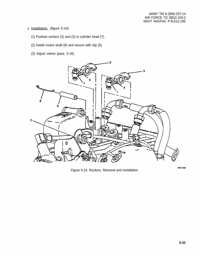
ARMY TM 9-2805-257-14AIR FORCE TO 38G2-103-2
NAVY NAVFAC P-8-612-14E
c. Installation. (figure 5-14)
(1) Position rockers (2) and (3) in cylinder head (7).
(2) Install rocker shaft (6) and secure with clip (5).
(3) Adjust valves (para. 5-16).
Figure 5-14. Rockers, Removal and Installation.
5-33
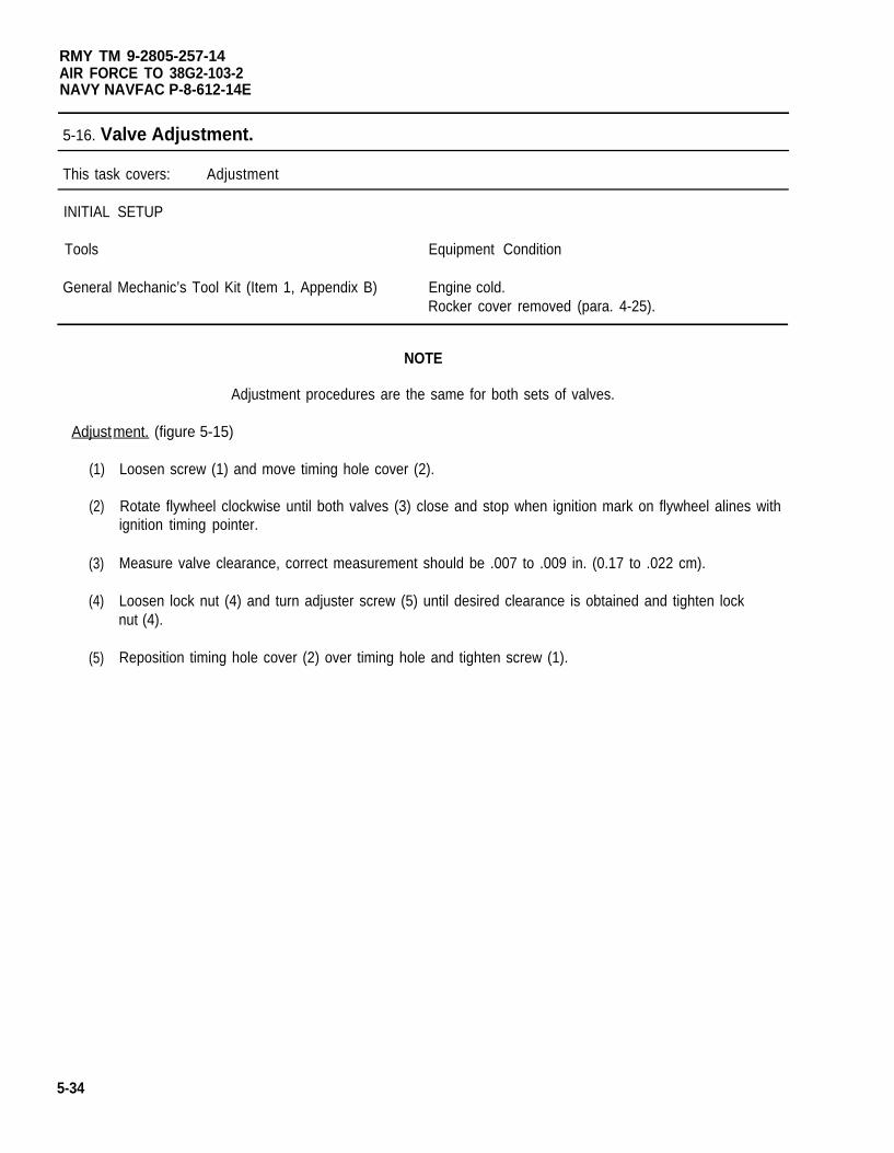
RMY TM 9-2805-257-14AIR FORCE TO 38G2-103-2NAVY NAVFAC P-8-612-14E
5-16. Valve Adjustment.
This task covers: Adjustment
INITIAL SETUP
Tools Equipment Condition
General Mechanic’s Tool Kit (Item 1, Appendix B) Engine cold.Rocker cover removed (para. 4-25).
NOTE
Adjustment procedures are the same for both sets of valves.
Adjustment. (figure 5-15)
(1)
(2)
(3)
(4)
(5)
5-34
Loosen screw (1) and move timing hole cover (2).
Rotate flywheel clockwise until both valves (3) close and stop when ignition mark on flywheel alines withignition timing pointer.
Measure valve clearance, correct measurement should be .007 to .009 in. (0.17 to .022 cm).
Loosen lock nut (4) and turn adjuster screw (5) until desired clearance is obtained and tighten locknut (4).
Reposition timing hole cover (2) over timing hole and tighten screw (1).
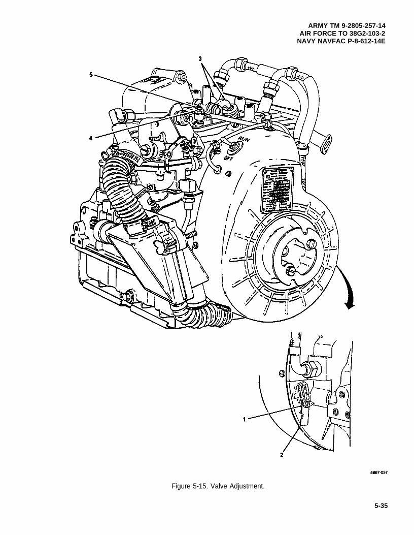
Figure 5-15. Valve Adjustment.
ARMY TM 9-2805-257-14AIR FORCE TO 38G2-103-2
NAVY NAVFAC P-8-612-14E
5-35
ARMY TM 9-2805-257-14AIR FORCE TO 38G2-103-2NAVY NAVFAC P-8-612-14E
5-17. Intake and Exhaust Valves.
This task covers: a. Removal b. Installation
INITIAL SETUP
Tools Equipment Condition
General Mechanic’s Tool Kit (item 1, Appendix B) Cylinder head assembly removed (para. 5-14).Compressor, Valve Spring (NSN 5330-00-096-6677)
(Item 3, Appendix B)
a. Removal. (figure 5-16)
NOTE
The removal and installation procedures are the same for intake and exhaust valve.
(1) Remove rocker shaft clip (1) and remove rocker shaft (2).
(2) Remove rocker arm (3).
(3) Using suitable valve spring compressor, compress valve spring (4) and remove two retainers (5), valve(6), spring (4) and rotocap (7).
(4) Replace any damaged or defective parts. Refer to Table 5-2 for wear limits.
b. Instalation. (figure 5-16)
(1) Install valve (6), spring (4), rotocap (7) in cylinder head (8).
(2) Using suitable valve spring compressor compress spring (4) and install two retainers (5).
(3) Install rocker arm (3), rocker shaft (2) and rocker shaft clip (1).
5-36
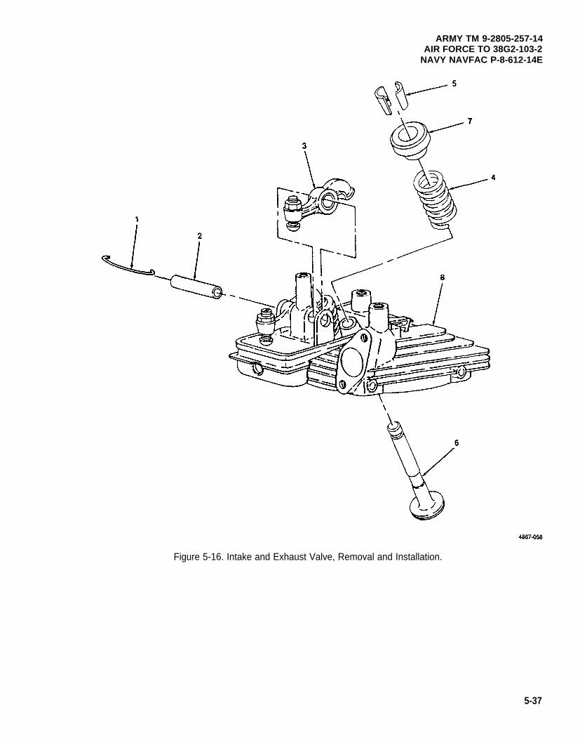
ARMY TM 9-2805-257-14AIR FORCE TO 38G2-103-2
NAVY NAVFAC P-8-612-14E
Figure 5-16. Intake and Exhaust Valve, Removal and Installation.
5-37
ARMY TM 9-2805-257-14AIR FORCE TO 38G2-103-2NAVY NAVFAC P-8-612-14E
5-18. Piston and Connecting Rod Assembly.
This task covers: a. Removal b. Repair c. Installation
INITIAL SETUP
Tools Materials/Parts (cont)
General Mechanic’s Tool Kit (Item 1, Appendix B) Lockwasher, Tab (NSN 2805-00-439-8116)Wrench, Torque (NSN 5120-00-230-6380) Ring, Retaining (NSN 5365-00-070-1928)
(Item 3, Appendix B)Compressor, Ring (NSN 5120-00-250-6055) Equipment Condition
Materials/Parts Cylinder head assembly removed (para. 5-14)Oil pan removed (para 5-7).
Rags, Wiping (Item 6, Appendix D)Solvent, Drycleaning (Item 7, Appendix D)Rings, Piston (NSN 2805-01-093-2392)
a. Removal. (figure 5-17)
(1)
(2)
(3)
(4)
5-38
WARNING
Dry cleaning solvent PD-680 used to clean parts is potentially dangerous to personneland property. Avoid repeated and prolonged skin contact. Do not use near open flameor excessive heat. Flash point of solvent is 100°F -138°F (38°C-60°C).
NOTE
This engine is equipped with two piston and connecting rod assemblies, the removal andinstallation procedures are the same for both.
Remove carbon deposits from top of piston (1) and cylinder wall (2) and clean with dry cleaning solvent.
Bend tangs on Iockwasher (3) out.
Remove bearing cap bolt (4), dipper bolt (5), Iockwasher (3) and remove connecting rod cap (6).
Slide piston (1) out of cylinder (7).
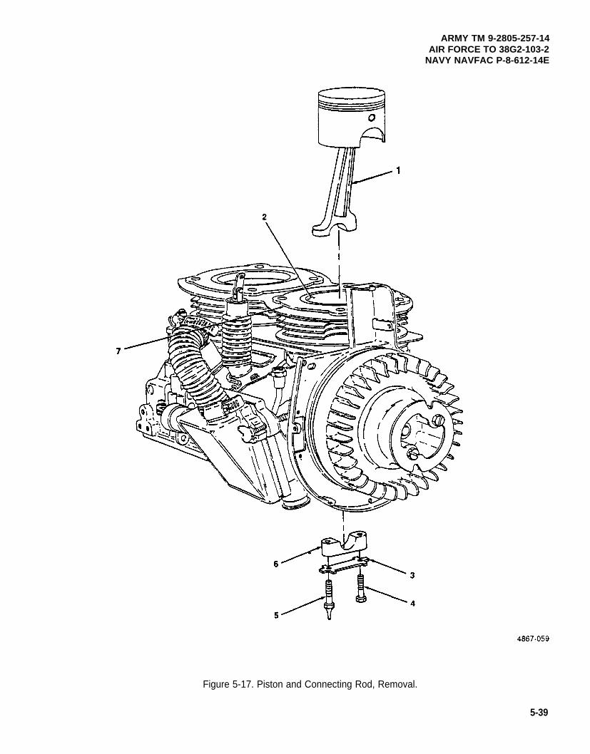
ARMY TM 9-2805-257-14AIR FORCE TO 38G2-103-2
NAVY NAVFAC P-8-612-14E
Figure 5-17. Piston and Connecting Rod, Removal.
5-39
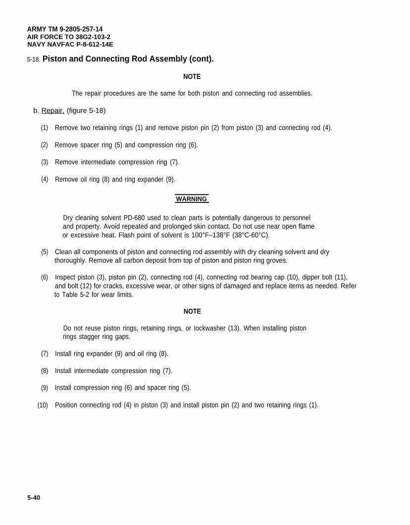
ARMY TM 9-2805-257-14AIR FORCE TO 38G2-103-2NAVY NAVFAC P-8-612-14E
5-18. Piston and Connecting Rod Assembly (cont).
NOTE
The repair procedures are the same for both piston and connecting rod assemblies.
b. Repair. (figure 5-18)
(1)
(2)
(3)
(4)
(5)
(6)
(7)
(8)
(9)
(10)
5-40
Remove two retaining rings (1) and remove piston pin (2) from piston (3) and connecting rod (4).
Remove spacer ring (5) and compression ring (6).
Remove intermediate compression ring (7).
Remove oil ring (8) and ring expander (9).
WARNING
Dry cleaning solvent PD-680 used to clean parts is potentially dangerous to personneland property. Avoid repeated and prolonged skin contact. Do not use near open flameor excessive heat. Flash point of solvent is 100°F–138°F (38°C-60°C).
Clean all components of piston and connecting rod assembly with dry cleaning solvent and drythoroughly. Remove all carbon deposit from top of piston and piston ring groves.
Inspect piston (3), piston pin (2), connecting rod (4), connecting rod bearing cap (10), dipper bolt (11),and bolt (12) for cracks, excessive wear, or other signs of damaged and replace items as needed. Referto Table 5-2 for wear limits.
NOTE
Do not reuse piston rings, retaining rings, or Iockwasher (13). When installing pistonrings stagger ring gaps.
Install ring expander (9) and oil ring (8).
Install intermediate compression ring (7).
Install compression ring (6) and spacer ring (5).
Position connecting rod (4) in piston (3) and install piston pin (2) and two retaining rings (1).
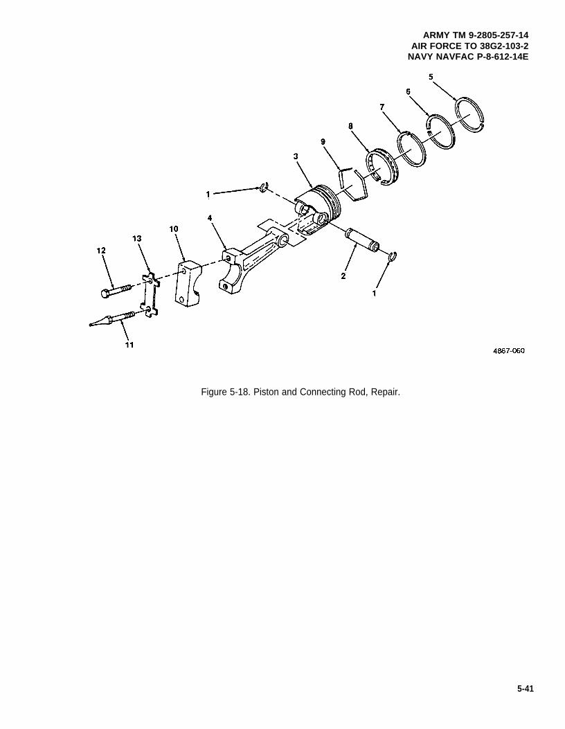
ARMY TM 9-2805-257-14AIR FORCE TO 38G2-103-2
NAVY NAVFAC P-8-612-14E
Figure 5-18. Piston and Connecting Rod, Repair.
5-41
ARMY TM 9-2805-257-14AIR FORCE TO 38G2-103-2NAVY NAVFAC P-8-612-14E
5-18. Piston and Connecting Rod Assembly (cont).
c. Installation. (figure 5-19)
(1)
(2)
(3)
5-42
NOTE
Use a suitable ring compressor when installing piston in cylinder.
Install piston and connecting rod assembly (1) in cylinder (7) and position the connecting rod oncrankshaft (8).
NOTE
Install a new Iockwasher. Do not reuse old Iockwasher.
Install connecting rod bearing cap (6) and Iockwasher (3) and secure with dipper bolt (5) and bolt (4).Torque bolts to 90-100 in. Ibs (10047-17860gm. cm.).
Bend tangs on Iockwasher (3) around bolt and dipper bolt head.
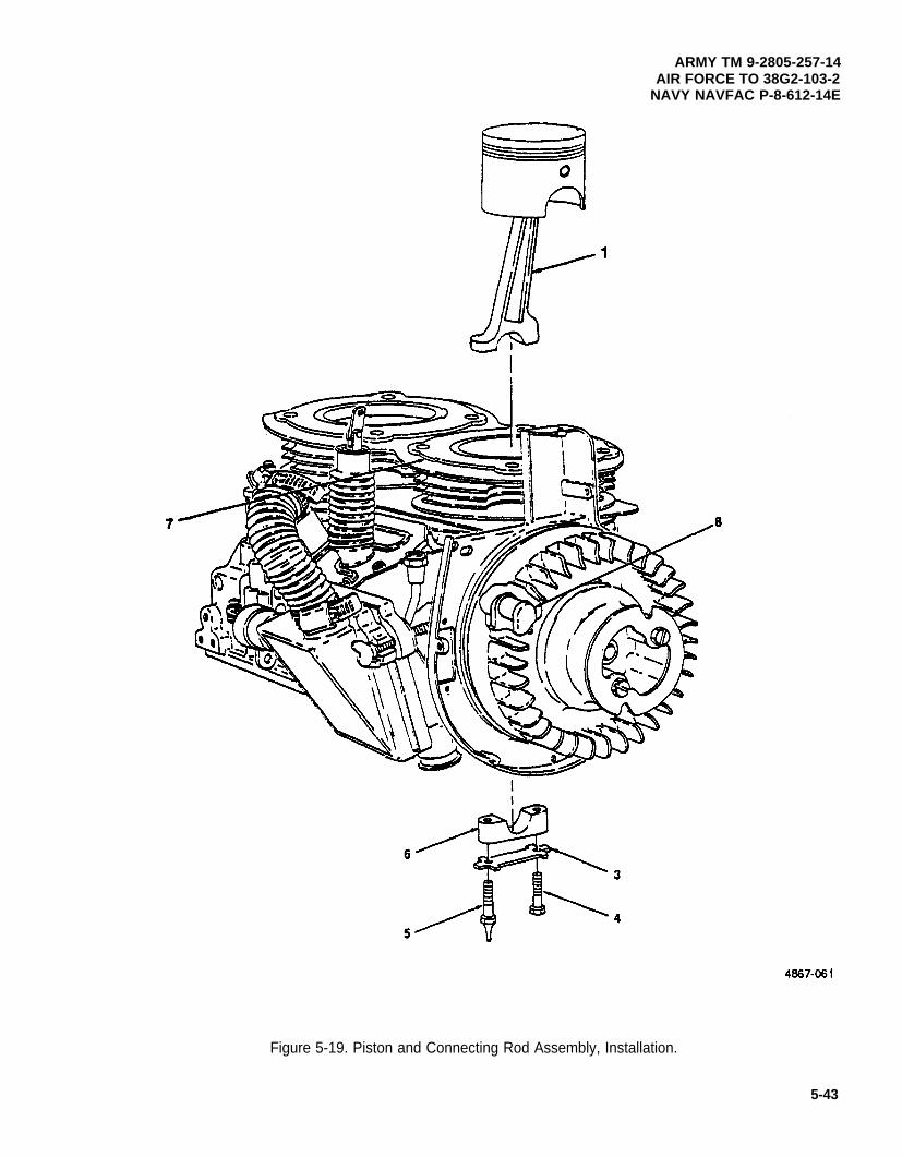
ARMY TM 9-2805-257-14AIR FORCE TO 38G2-103-2
NAVY NAVFAC P-8-612-14E
Figure 5-19. Piston and Connecting Rod Assembly, Installation.
5-43
ARMY TM 9-2805-257-14AIR FORCE TO 38G2-103-2NAVY NAVFAC P-8-612-14E
5-19. Rotating Magnet.
This task covers: a. Removal b. Installation
INITIAL SETUP
Tools Equipment Condition
General Mechanic’s Tool Kit (item 1, Appendix B) Flywheel removed (para. 4-38).Puller, Kit Mechanical (NSN 5120-00-423-1596)(Item 3, Appendix B)
a. Removal. (figure 5-20)
NOTE
In the event the rotating magnet cannot be removed as a single assembly, replace theentire rotating magnet.
(1) Mark the face of rotating magnet to ensure proper installation.
(2) Using suitable puller, remove rotating magnet (1) and key (2) from crankshaft (3).
b. Installation. (figure 5-20)
(1) Install key (2) on crankshaft (3).
(2) Ensure proper orientation of rotating magnet (1) and install it on crankshaft (3).
5-44
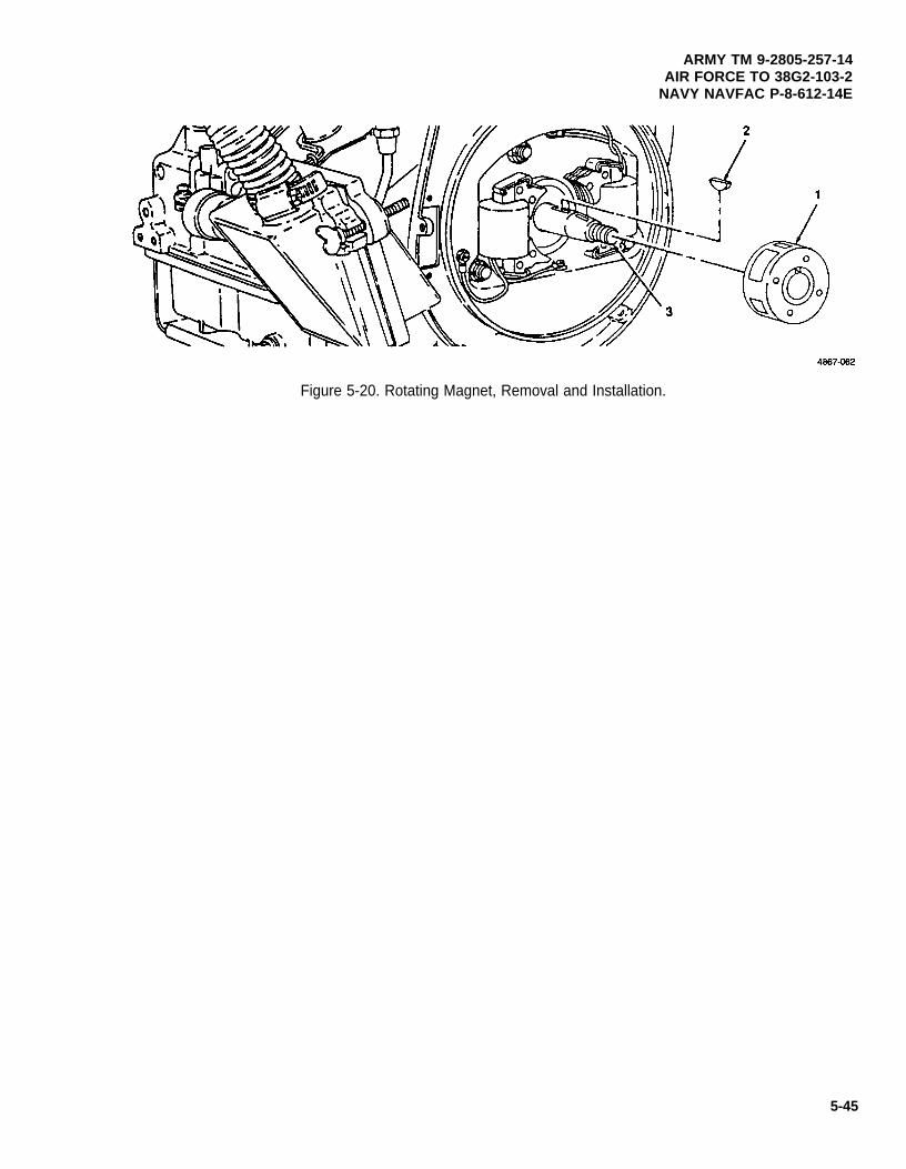
Figure 5-20. Rotating Magnet, Removal and Installation.
ARMY TM 9-2805-257-14AIR FORCE TO 38G2-103-2
NAVY NAVFAC P-8-612-14E
5-45
ARMY TM 9-2805-257-14AIR FORCE TO 38G2-103-2NAVY NAVFAC P-8-612-14E
5-20. Coil.
This task covers: a. Removal b. Test c. Installation.
INITIAL SETUP
Tools Equipment Condition
General Mechanic’s Tool Kit (Item 1, Appendix B) Flywheel removed (para.Multimeter (NSN 6625-01-139-2512)
(Item 2, Appendix B)
4-38).
a. Removal. (figure 5-21)
WARNING
Use extreme care when removing coil clamps. Flying clamps can cause severe eyeinjury, cover work area with rag or hand when removing clamps.
NOTE
Make note of coil leads placement before removing coil.
Engines with breakerless ignition system have only one coil.
(1) Remove two coil clamps (1) securing coil (2) and remove.
(2) Tag and disconnect coil leads.
(1) Perform resistance test between leads of coil.
(2) Resistance for coil in breakerless ignition system should be 320 ± 20 ohms.
(3) Resistance of coils for breaker point ignition system areas follows:
Primary windings Secondary windingsManufacturer (ohms) (ohms)
Bendix Corp. 0.512 ± 0.050 3,300 ± 400Colt Industries 0.370 ± 0.025 8,500 ± 700Motor Parts. Inc. 0.370 ± 0.025 8,500 ± 700
(4) if the measured resistance does not match specified resistance then replace coil.
5-46
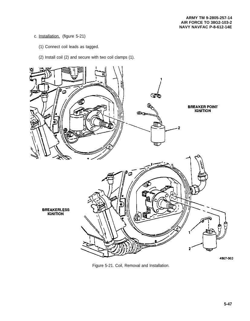
ARMY TM 9-2805-257-14AIR FORCE TO 38G2-103-2
NAVY NAVFAC P-8-612-14E
c. Installation. (figure 5-21)
(1) Connect coil leads as tagged.
(2) Install coil (2) and secure with two coil clamps (1).
Figure 5-21. Coil, Removal and Installation.
5-47
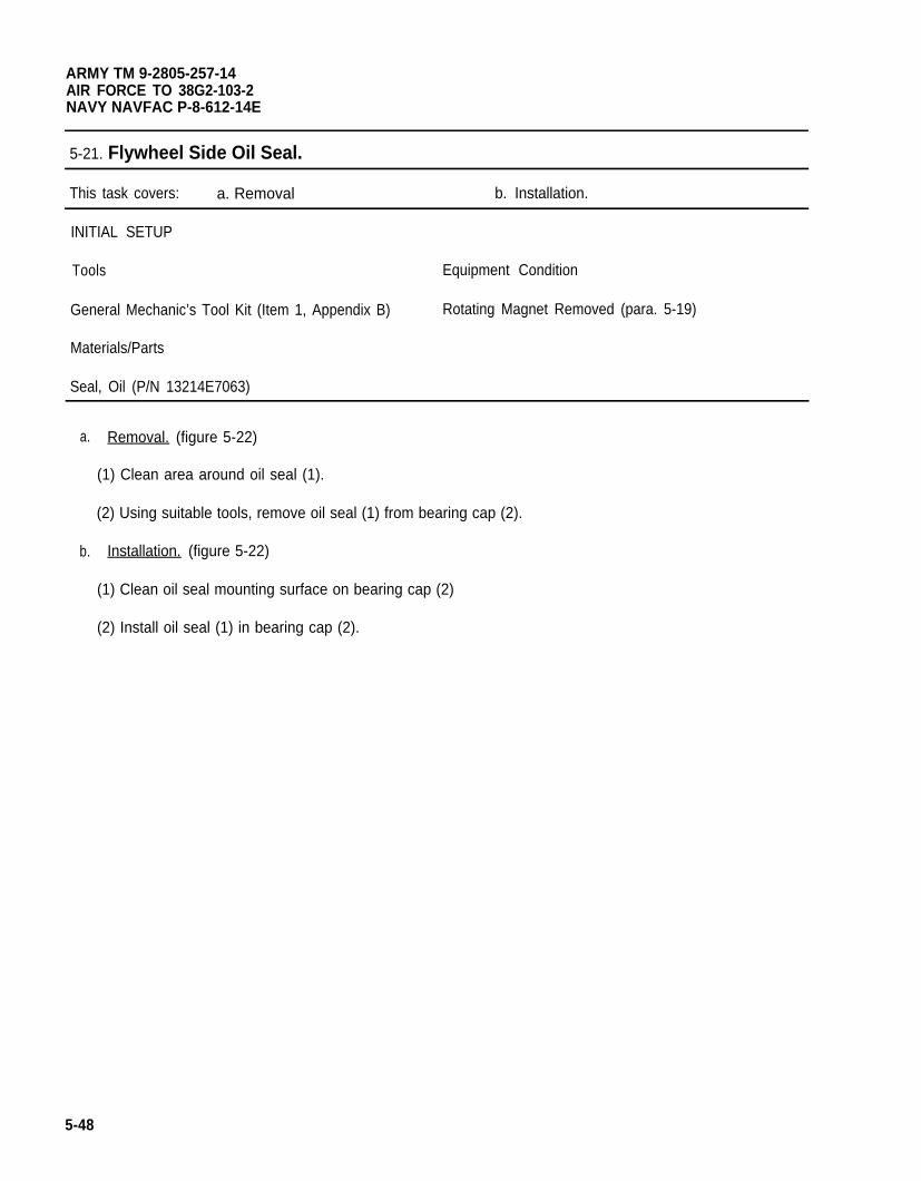
ARMY TM 9-2805-257-14AIR FORCE TO 38G2-103-2NAVY NAVFAC P-8-612-14E
5-21. Flywheel Side Oil Seal.
This task covers: a. Removal b. Installation.
INITIAL SETUP
Tools Equipment Condition
General Mechanic’s Tool Kit (Item 1, Appendix B)
Materials/Parts
Seal, Oil (P/N 13214E7063)
Rotating Magnet Removed (para. 5-19)
a.
b.
Removal. (figure 5-22)
(1) Clean area around oil seal (1).
(2) Using suitable tools, remove oil seal (1) from bearing cap (2).
Installation. (figure 5-22)
(1) Clean oil seal mounting surface on bearing cap (2)
(2) Install oil seal (1) in bearing cap (2).
5-48
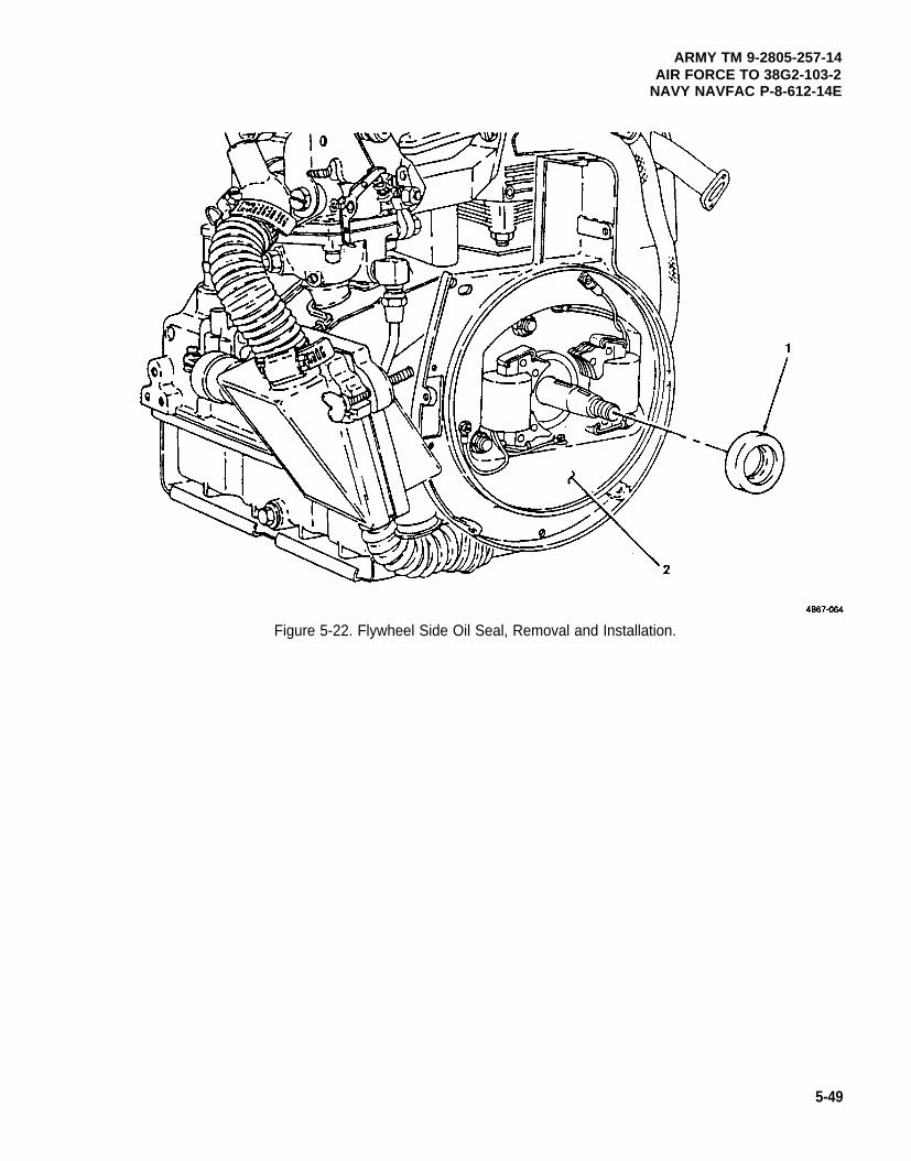
ARMY TM 9-2805-257-14AIR FORCE TO 38G2-103-2
NAVY NAVFAC P-8-612-14E
Figure 5-22. Flywheel Side Oil Seal, Removal and Installation.
5-49
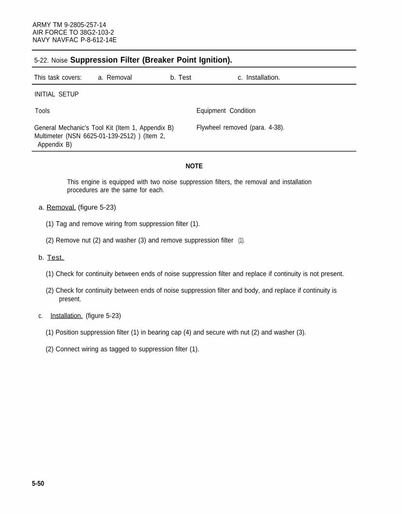
ARMY TM 9-2805-257-14AIR FORCE TO 38G2-103-2NAVY NAVFAC P-8-612-14E
5-22. Noise Suppression Filter (Breaker Point Ignition).
This task covers: a. Removal b. Test c. Installation.
INITIAL SETUP
Tools Equipment Condition
General Mechanic’s Tool Kit (Item 1, Appendix B) Flywheel removed (para. 4-38).Multimeter (NSN 6625-01-139-2512) ) (Item 2,Appendix B)
NOTE
This engine is equipped with two noise suppression filters, the removal and installationprocedures are the same for each.
a. Removal. (figure 5-23)
(1) Tag and remove wiring from suppression filter (1).
(2) Remove nut (2) and washer (3) and remove suppression filter
b. Test.
(1).
(1) Check for continuity between ends of noise suppression filter and replace if continuity is not present.
(2) Check for continuity between ends of noise suppression filter and body, and replace if continuity ispresent.
c. Installation. (figure 5-23)
(1) Position suppression filter (1) in bearing cap (4) and secure with nut (2) and washer (3).
(2) Connect wiring as tagged to suppression filter (1).
5-50
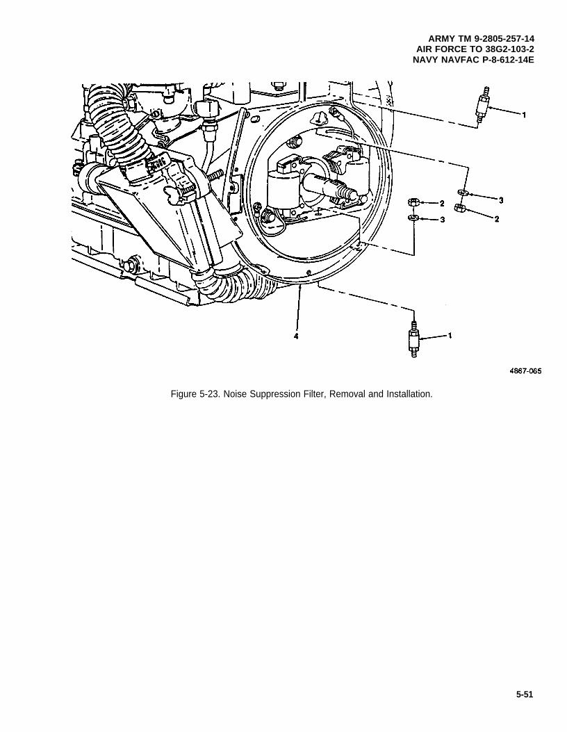
ARMY TM 9-2805-257-14AIR FORCE TO 38G2-103-2
NAVY NAVFAC P-8-612-14E
Figure 5-23. Noise Suppression Filter, Removal and Installation.
5-51
ARMY TM 9-2805-257-14AIR FORCE TO 38G2-103-2NAVY NAVFAC P-8-612-14E
5-23. Crankshaft Side Oil Seal.
This task covers: a. Removal b. Installation.
INITIAL SETUP
Tools Materials/Parts
General Mechanic’s Tool Kit (Item 1, Appendix B) Seal, Oil (P/N 13214E7063)
a. Removal. (figure 5-24)
(1) Clean area around oil seal (1).
(2) Using suitable tools, remove oil seal (1) from crankcase (2).
b. Installation. (figure 5-24)
(1) Clean crankcase mounting surface.
(2) Install oil seal (1) in crankcase (2).
5-52
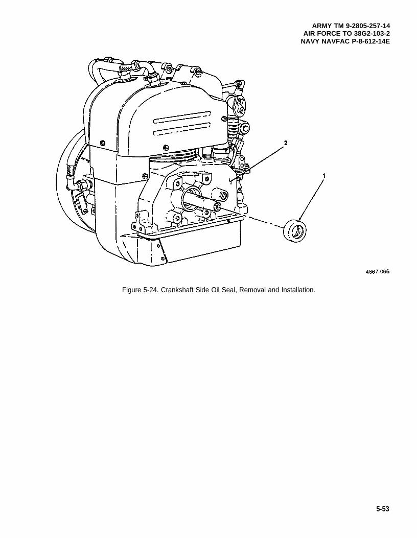
ARMY TM 9-2805-257-14AIR FORCE TO 38G2-103-2
NAVY NAVFAC P-8-612-14E
Figure 5-24. Crankshaft Side Oil Seal, Removal and Installation.
5-53
ARMY TM 9-2805-257-14AIR FORCE TO 38G2-103-2NAVY NAVFAC P-8-612-14E
5-24. Compression Test.
This task covers: Test
INITIAL SETUP
Tools
General Mechanic’s Tool Kit (Item 1, Appendix B)Tester, Cylinder Compression (NSN 4910-00-250-2423)
(Item 2, Appendix B)
NOTE
This engine is equipped with two cylinders, the procedures for compression test is thesame for both.
Test. (figure 5-25)
(1)
(2)
(3)
(4)
(5)
(6)
(7)
Disconnect ignition cable (1) from spark plug (2).
Remove spark plug (2) from engine (3).
Install suitable pressure gage (4) in spark plug hole.
Using starter rope crank engine several times, and check pressure gage.
NOTE
As altitude increases cylinder compression will decrease.
Cylinder compression should be a minimum of 90 psi (63279 kpa) at sea level.
Remove pressure gage (4).
Install spark plug (2), and connect ignition cable (1).
5-54
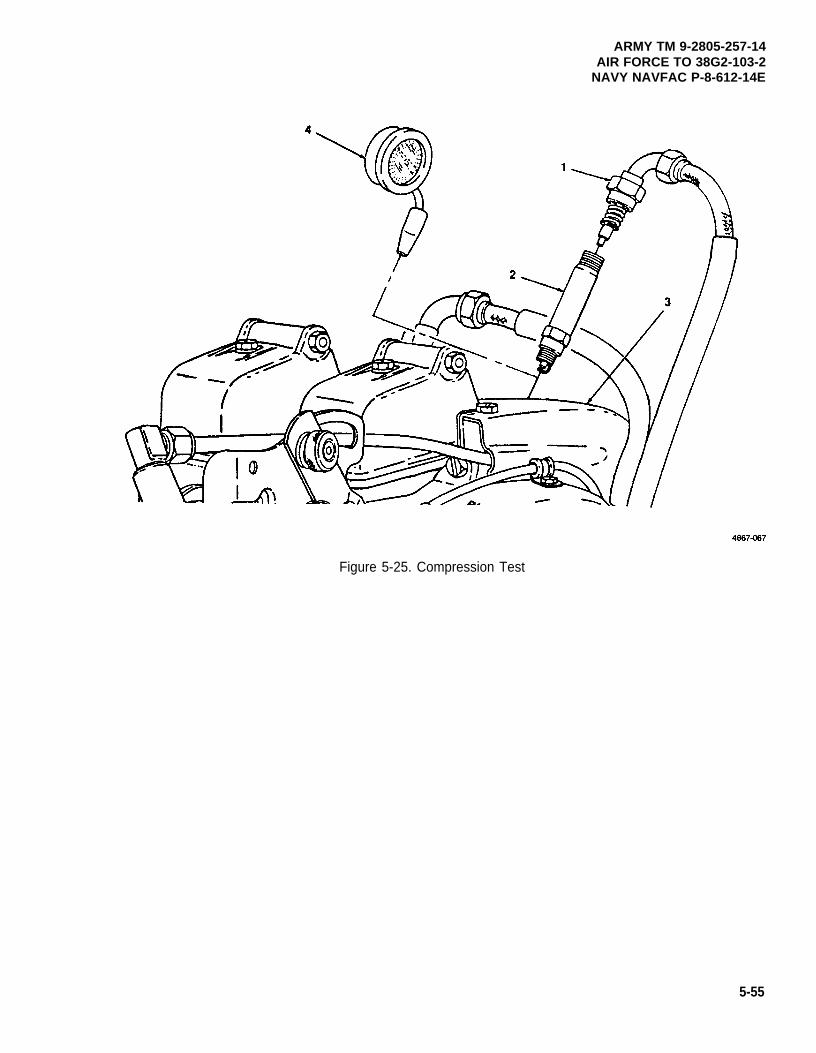
ARMY TM 9-2805-257-14AIR FORCE TO 38G2-103-2
NAVY NAVFAC P-8-612-14E
Figure 5-25. Compression Test
5-55
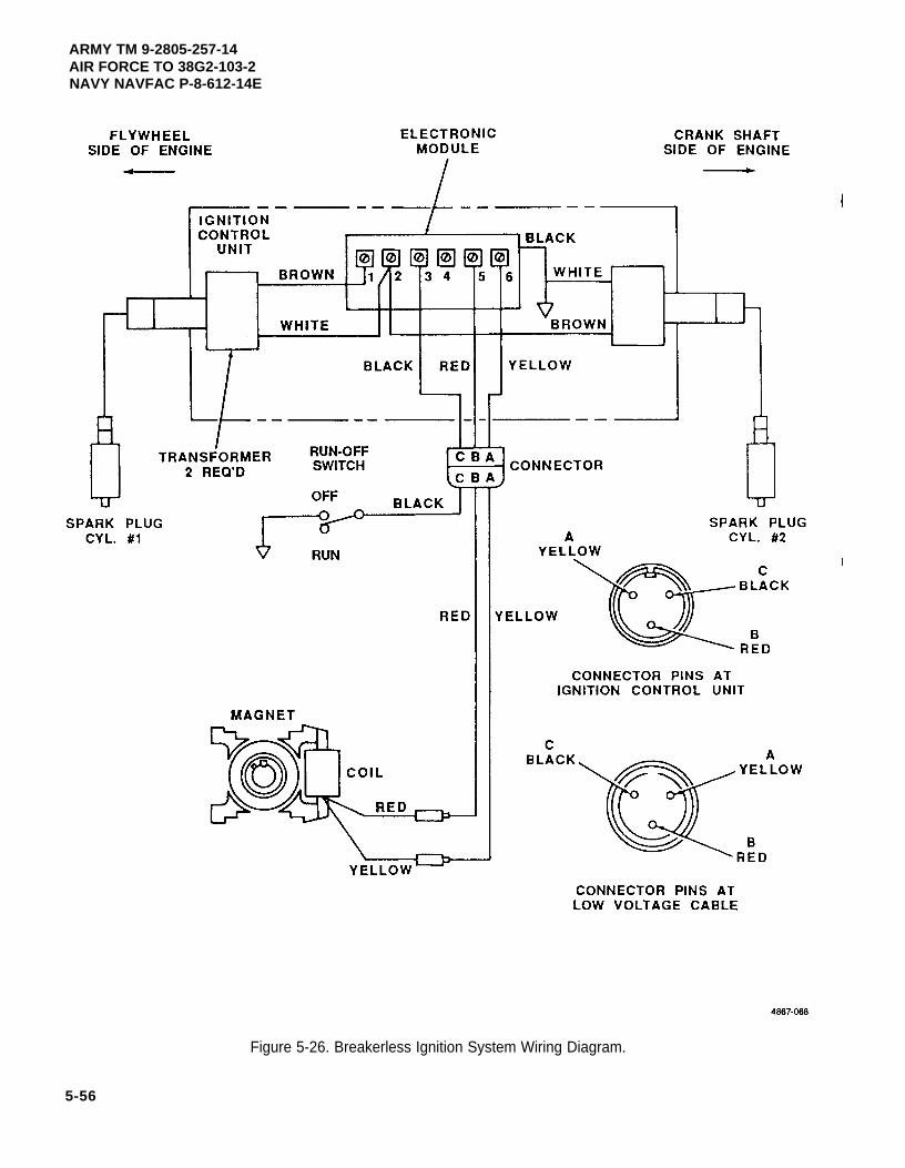
ARMY TM 9-2805-257-14AIR FORCE TO 38G2-103-2NAVY NAVFAC P-8-612-14E
5-56
Figure 5-26. Breakerless Ignition System Wiring Diagram.
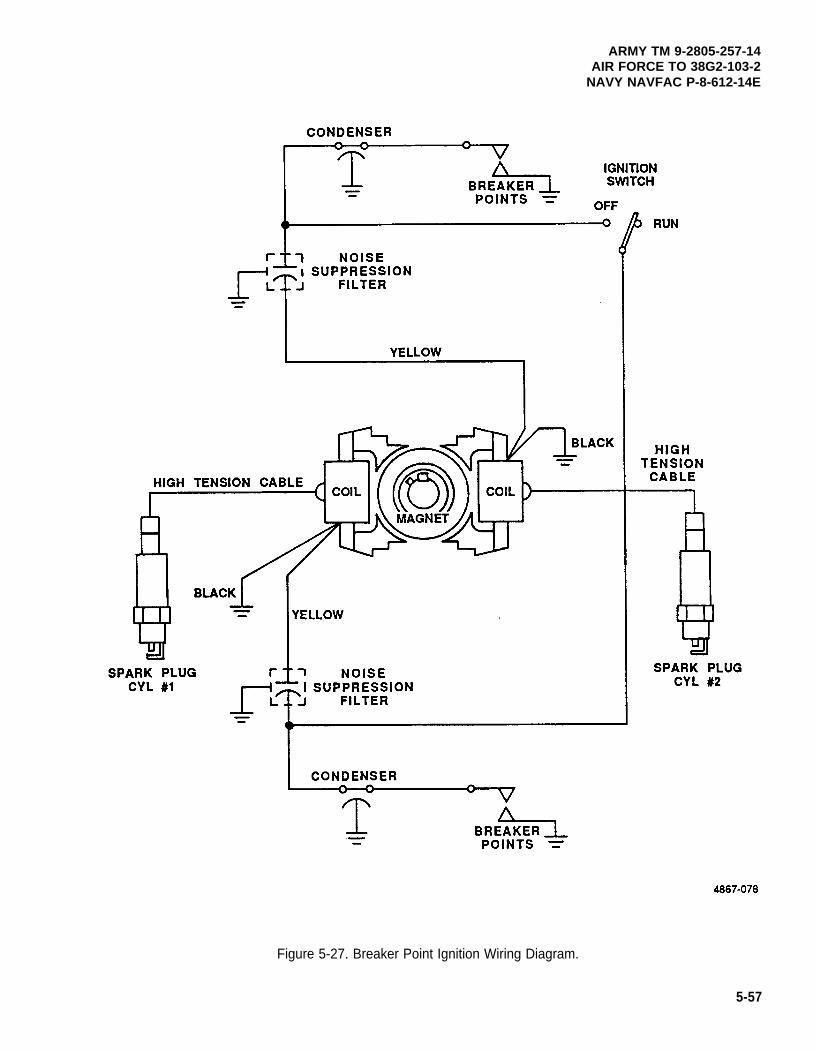
ARMY TM 9-2805-257-14AIR FORCE TO 38G2-103-2
NAVY NAVFAC P-8-612-14E
Figure 5-27. Breaker Point Ignition Wiring Diagram.
5-57
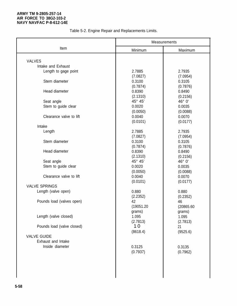
ARMY TM 9-2805-257-14AIR FORCE TO 38G2-103-2NAVY NAVFAC P-8-612-14E
Table 5-2. Engine Repair and Replacements Limits.
Item
VALVESIntake and Exhaust
Length to gage point
Stem diameter
Head diameter
Seat angleStem to guide clear
Clearance valve to lift
IntakeLength
Stem diameter
Head diameter
Seat angleStem to guide clear
Clearance valve to lift
VALVE SPRINGSLength (valve open)
Pounds load (valves open)
Length (valve closed)
Pounds load (valve closed)
VALVE GUIDEExhaust and Intake
Inside diameter
Measurements
Minimum
2.7885(7.0827)0.3100(0.7874)0.8390(2.1310)45° 45’0.0020(0.0050)0.0040(0.0101)
2.7885(7.0827)0.3100(0.7874)0.8390(2.1310)45° 45’0.0020(0.0050)0.0040(0.0101)
0.880(2.2352)42(19051.20grams)1.095(2.7813)1 0
(8618.4)
0.3125(0.7937)
Maximum
2.7935(7.0954)0.3105(0.7876)0.8490(0.2156)46° 0’0.0035(0.0088)0.0070(0.0177)
2.7935(7.0954)0.3105(0.7876)0.8490(0.2156)46° 0’0.0035(0.0088)0.0070(0.0177)
0.880(0.2352)46(20865.60grams)1.095(2.7813)21(9525.6)
0.3135(0.7962)
5-58
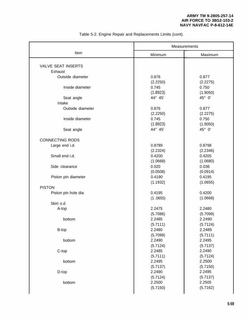
ARMY TM 9-2805-257-14AIR FORCE TO 38G2-103-2
NAVY NAVFAC P-8-612-14E
Table 5-2. Engine Repair and Replacements Limits (cont).
Item
VALVE SEAT INSERTSExhaust
Outside diameter
Inside diameter
Seat angleIntake
Outside diameter
Inside diameter
Seat angle
CONNECTING RODSLarge end i.d.
Small end i.d.
Side clearance
Piston pin diameter
PISTONPiston pin hole dia
Skirt o.d.A-top
bottom
B-top
bottom
C-top
bottom
D-top
bottom
Measurements
Minimum
0.876(2.2250)0.745(1.8923)44° 45’
0.876(2.2250)0.745(1.8923)44° 45’
0.8789(2.2324)0.4200(1.0668)0.020(0.0508)0.4190(1.1932)
0.4195(1 .0655)
2.2475(5.7086)2.2485(5.7111)2.2480(5.7099)2.2490(5.7124)2.2485(5.7111)2.2495(5.7137)2.2490(5.7124)2.2500(5.7150)
Maximum
0.877(2.2275)0.750(1.9050)45° 0’
0.877(2.2275)0.750(1.9050)45° 0’
0.8798(2.2346)0.4205(1.0680)0.036(0.0914)0.4195(1.0655)
0.4200(1.0668)
2.2480(5.7099)2.2490(5.7124)2.2485(5.7111)2.2495(5.7137)2.2490(5.7124)2.2500(5.7150)2.2495(5.7137)2.2505(5.7162)
5-59
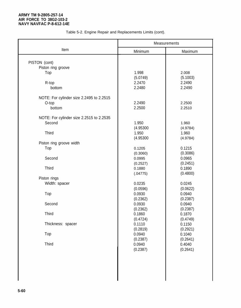
ARMY TM 9-2805-257-14AIR FORCE TO 38G2-103-2NAVY NAVFAC P-8-612-14E
Table 5-2. Engine Repair and Replacements Limits (cont).
Item
PISTON (cont)Piston ring groove
Top
R-topbottom
NOTE: For cylinder size 2.2495 to 2.2515O-top
bottom
NOTE: For cylinder size 2.2515 to 2.2535Second
Third
Piston ring groove widthTop
Second
Third
Piston ringsWidth: spacer
Top
Second
Third
Thickness: spacer
Top
Third
Measurements
Minimum
1.998(5.0749)2.24702.2480
2.24902.2500
1.950(4.953001.950(4.95300
0.1205(0.3060)0.0995(0.2527)0.1880(.04775)
0.0235(0.0596)0.0930(0.2362)0.0930(0.2362)0.1860(0.4724)0.1110(0.2819)0.0940(0.2387)0.0940(0.2387)
Maximum
2.008(5.1003)2.24902.2490
2.25002.2510
1.960(4.9784)1.960(4.9784)
0.1215(0.3086)0.0965(0.2451)0.1890(0.4800)
0.0245(0.0622)0.0940(0.2387)0.0940(0.2387)0.1870(0.4749)0.1150(0.2921)0.1040(0.2641)0.4040(0.2641)
5-60
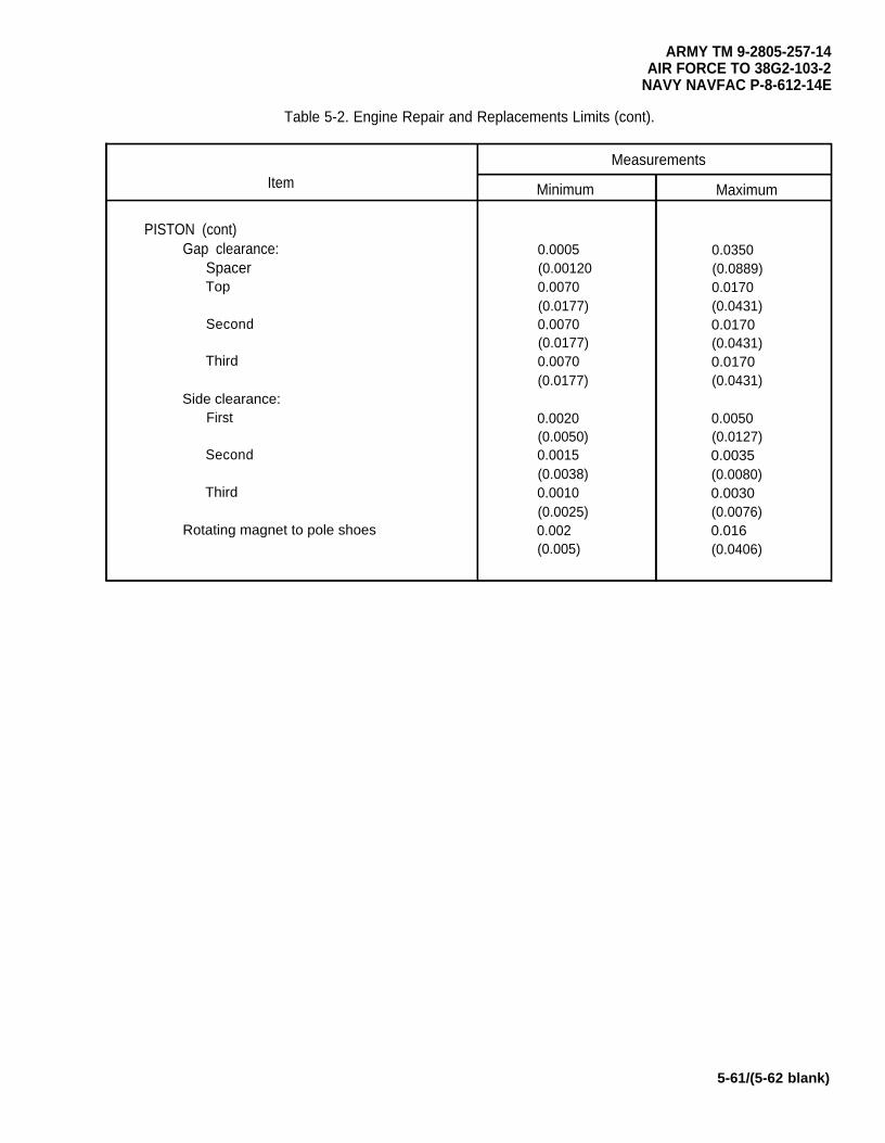
ARMY TM 9-2805-257-14AIR FORCE TO 38G2-103-2
NAVY NAVFAC P-8-612-14E
Table 5-2. Engine Repair and Replacements Limits (cont).
Measurements
Item Minimum Maximum
PISTON (cont)Gap clearance: 0.0005 0.0350
Spacer (0.00120 (0.0889)Top 0.0070 0.0170
(0.0177) (0.0431)Second 0.0070 0.0170
(0.0177) (0.0431)Third 0.0070 0.0170
(0.0177) (0.0431)Side clearance:
First 0.0020 0.0050(0.0050) (0.0127)
Second 0.0015 0.0035(0.0038) (0.0080)
Third 0.0010 0.0030(0.0025) (0.0076)
Rotating magnet to pole shoes 0.002 0.016(0.005) (0.0406)
5-61/(5-62 blank)

ARMY TM 9-2805-257-14AIR FORCE TO 38G2-103-2
NAVY NAVFAC P-8-612-14E
CHAPTER 6
GENERAL SUPPORT MAINTENANCE INSTRUCTIONS
OVERVIEW . . . . . . . . . . . . . . . . . . . . . . . . . . . . . . . . . . . . . . . . . . . . . . . . . . . . . . . . . . . . . .Section l. Repair Parts; Special Tools; Test, Measurement, Diagnostic
Page
. . 6-1
Equipment (TMDE); and Support Equipment . . . . . . . . . . . . . . . . . . . . . . . . . . . . . . 6-1Section Il. General Support Troubleshooting . . . . . . . . . . . . . . . . . . . . . . . . . . . . . . . . . . . . ...6-1Section lll. General Support Maintenance Procedures . . . . . . . . . . . . . . . . . . . . . . . . . . . . . . . . 6-3
OVERVIEW
This chapter provides procedures for troubleshooting and maintenance of the 3 HP Military Standard Engine byGeneral Support maintenance personnel.
Section I. REPAIR PARTS; SPECIAL TOOLS; TEST, MEASUREMENT, DIAGNOSTICEQUIPMENT (TMDE); AND SUPPORT EQUIPMENT
Paragraph Page
6-1 Common Tools and Test Equipment . . . . . . . . . . . . . . . . . . . . . . . . . . . . . . . . . . . . . . ...6-16-2 Special Tools, TMDE, and Support Equipment . . . . . . . . . . . . . . . . . . . . . . . . . . . . . . . . . 6-16-3 Repair Parts . . . . . . . . . . . . . . . . . . . . . . . . . . . . . . . . . . . . . . . . . . . . . . . . . . . . . . . . . ...6-1
6-1. Common Tools and Test Equipment. For authorized common tools and equipment, refer to theModified Table of Organization and Equipment (MTOE) applicable to your unit.
6-2. Special Tools, TMDE and Support Equipment. For a listing of special tools, TMDE, and supportequipment authorized for use on this equipment, refer to the Repair Parts and Special Tools List, TM 5-2805-257-24P, and the maintenance allocation chart (MAC), appendix B of this manual.
6-3. Repair Parts. Repair parts are listed and illustrated in the Repair Parts and Special Tools List for 3 HPMilitary Standard Engine TM 5-2805-257-24P.
Section II. GENERAL SUPPORT TROUBLESHOOTING
Paragraph Page
6-4 General . . . . . . . . . . . . . . . . . . . . . . . . . . . . . . . . . . . . . . . . . . . . . . . . . . . . . . . . . . . . ...6-16-5 General Support Troubleshooting Procedures . . . . . . . . . . . . . . . . . . . . . . . . . . . . . . . . . 6-2
6-4. General. This section contains troubleshooting procedures to determine the probable cause of observedequipment malfunctions. Tests or inspections are provided to isolate the faulty component and corrective actionsare provided to eliminate the malfunction.
6-1
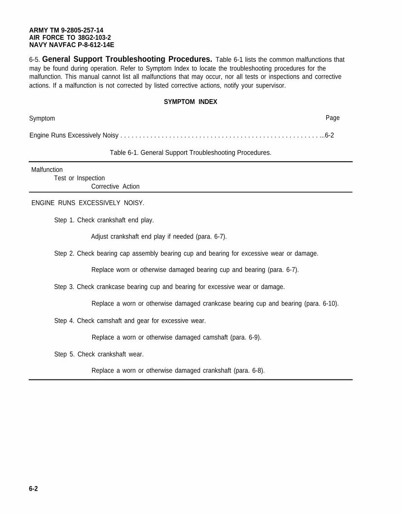
ARMY TM 9-2805-257-14AIR FORCE TO 38G2-103-2NAVY NAVFAC P-8-612-14E
6-5. General Support Troubleshooting Procedures. Table 6-1 lists the common malfunctions thatmay be found during operation. Refer to Symptom Index to locate the troubleshooting procedures for themalfunction. This manual cannot list all malfunctions that may occur, nor all tests or inspections and correctiveactions. If a malfunction is not corrected by listed corrective actions, notify your supervisor.
SYMPTOM INDEX
Symptom Page
Engine Runs Excessively Noisy . . . . . . . . . . . . . . . . . . . . . . . . . . . . . . . . . . . . . . . . . . . . . . . . . . . . . ...6-2
Table 6-1. General Support Troubleshooting Procedures.
MalfunctionTest or Inspection
Corrective Action
ENGINE RUNS EXCESSIVELY NOISY.
Step 1. Check crankshaft end play.
Adjust crankshaft end play if needed (para. 6-7).
Step 2. Check bearing cap assembly bearing cup and bearing for excessive wear or damage.
Replace worn or otherwise damaged bearing cup and bearing (para. 6-7).
Step 3. Check crankcase bearing cup and bearing for excessive wear or damage.
Replace a worn or otherwise damaged crankcase bearing cup and bearing (para. 6-10).
Step 4. Check camshaft and gear for excessive wear.
Replace a worn or otherwise damaged camshaft (para. 6-9).
Step 5. Check crankshaft wear.
Replace a worn or otherwise damaged crankshaft (para. 6-8).
6-2
ARMY TM 9-2805-257-14AIR FORCE TO 38G2-103-2
NAVY NAVFAC P-8-612-14E
Section Ill. GENERAL SUPPORT MAINTENANCE PROCEDURES
Paragraph Page
6-6 General . . . . . . . . . . . . . . . . . . . . . . . . . . . . . . . . . . . . . . . . . . . . . . . . . . . . . . . . . . . . ...6-36-7 Bearing Cap Assembly . . . . . . . . . . . . . . . . . . . . . . . . . . . . . . . . . . . . . . . . . . . . . . . . ...6-46-8 Crankshaft Assembly . . . . . . . . . . . . . . . . . . . . . . . . . . . . . . . . . . . . . . . . . . . . . . . . . . ...6-86-9 Camshaft Assembly . . . . . . . . . . . . . . . . . . . . . . . . . . . . . . . . . . . . . . . . . . . . . . . . . . . ...6-126-10 Crankcase Assembly . . . . . . . . . . . . . . . . . . . . . . . . . . . . . . . . . . . . . . . . . . . . . . . . . . ...6-16
6-6. General. This section contains general support maintenance procedures as authorized by the MAC inAppendix B of this manual. Table 6-2 at the end of this section, contains wear limits for those items maintained bygeneral support maintenance. Those items which to not meet the specified measurements must be replaced.Refer to Appendix E for torque values. All maintenance procedures require only one person to perform.
6-3
ARMY TM 9-2805-257-14AIR FORCE TO 38G2-103-2NAVY NAVFAC P-6-612-14E
6-7. Bearing Cap Assembly.
This task covers: a. Removal b. Repair c. Installation
INITIAL SETUP
Tools Equipment Condition
General Mechanic’s Tool Kit (Item 1, Appendix B) Air cleaner assembly removed (para. 4-21).Wrench, Torque (NSN 5120-00-230-6380) Ignition coils removed (para. 5-20).
(Item 3, Appendix B) Rotating magnet removed (para. 5-19).Low voltage cable removed (para. 5-13).
Materials/Parts
Rags, Wiping (Item 6, Appendix D)Solvent, Drycleaning (Item 7, Appendix D)Packing, Preformed (NSN 5330-00-608-6432)Seal (P/N 13214E7063)
a. Removal. (figure 6-1)
(1)
(2)
(3)
(4)
(5)
NOTE
Steps 1 through 4 are for engines equipped with breaker point ignition.
Loosen connector nut (1) and tag and remove high tension cable (2) from bearing cap (3).
Remove two screws (4) and washers (5) and remove high tension cable access plate (6).
Loosen connector nut (7) and tag and remove high tension cable (8) from bearing cap (3).
Tag and remove wiring from noise suppression filters (9).
Remove three nuts (10) and remove bearing cap (3), shims (11) and O-ring (12).
b. Repair. (figure 6-1)
(1)
(2)
(3)
6-4
WARNING
Drycleaning solvent PD-680 used to clean parts is potentially dangerous to personnel andproperty. Avoid repeated and prolonged skin contact. Do not use near open flame orexcessive heat. Flash point of solvent is 100°F-138°F (38°C-60°C).
Clean bearing cap (3) with dry cleaning solvent, and dry thoroughly.
Inspect bearing cap (3) for cracks or other damage and replace if damage is found.
Inspect flywheel side oil seal (15) for signs of wear and replace if damaged.
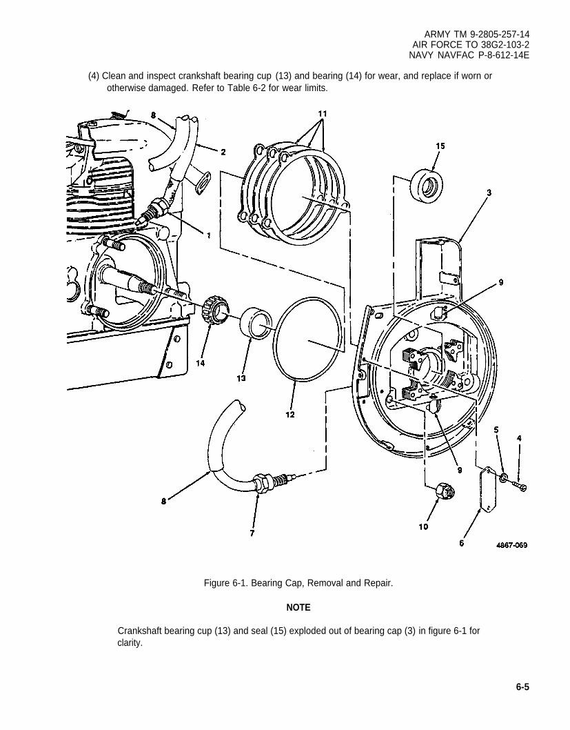
ARMY TM 9-2805-257-14AIR FORCE TO 38G2-103-2
NAVY NAVFAC P-8-612-14E
(4) Clean and inspect crankshaft bearing cup (13) and bearing (14) for wear, and replace if worn orotherwise damaged. Refer to Table 6-2 for wear limits.
Figure 6-1. Bearing Cap, Removal and Repair.
NOTE
Crankshaft bearing cup (13) and seal (15) exploded out of bearing cap (3) in figure 6-1 forclarity.
6-5
ARMY TM 9-2805-257-14AIR FORCE TO 38G2-103-2NAVY NAVFAC P-8-612-14E
6-7. Bearing Cap Assembly (cont).
c. Installation. (figure 6-2)
(1) Install bearing (14), O-ring (12), shims (11) and bearing cap (3) and secure with three nuts (10). Torquenuts to 100-125 in. Ibs. (17860-22325 gr cm).
(2) Check crankshaft end-play. Remove or install shims (11), as necessary, to obtain crankshaft end-play of.000-.003 in. (.000-.007 cm).
Note
(3)
(4)
(5)
(6)
Steps 3 through 6 are for engines equipped with breaker point ignition.
Connect wiring, as tagged to noise suppression filters (9).
Install high tension cable (8) and tighten connector nut (7).
Install high tension cable access plate (6) and secure with two screws (4) and washers (5).
Install high tension cable (2) and tighten connector nut (1).
6-6
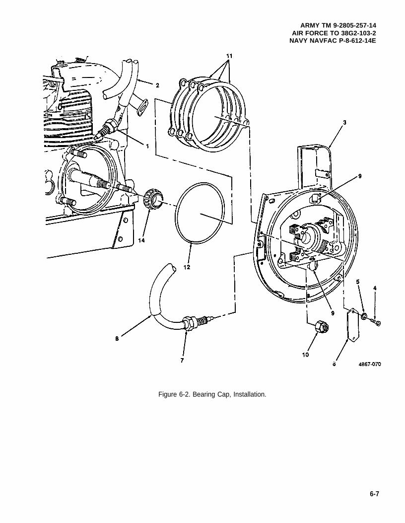
ARMY TM 9-2805-257-14AIR FORCE TO 38G2-103-2
NAVY NAVFAC P-8-612-14E
Figure 6-2. Bearing Cap, Installation.
6-7
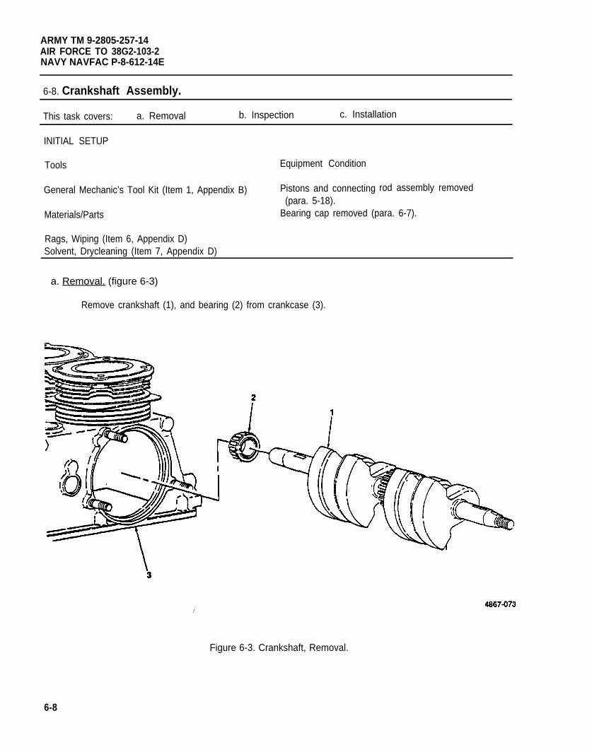
ARMY TM 9-2805-257-14AIR FORCE TO 38G2-103-2NAVY NAVFAC P-8-612-14E
6-8. Crankshaft Assembly.
This task covers: a. Removal b. Inspection c. Installation
INITIAL SETUP
Tools Equipment Condition
rod assembly removedGeneral Mechanic’s Tool Kit (Item 1, Appendix B) Pistons and connecting(para. 5-18).
Materials/Parts Bearing cap removed (para. 6-7).
Rags, Wiping (Item 6, Appendix D)Solvent, Drycleaning (Item 7, Appendix D)
a. Removal. (figure 6-3)
Remove crankshaft (1), and bearing (2) from crankcase (3).
Figure 6-3. Crankshaft, Removal.
6-8
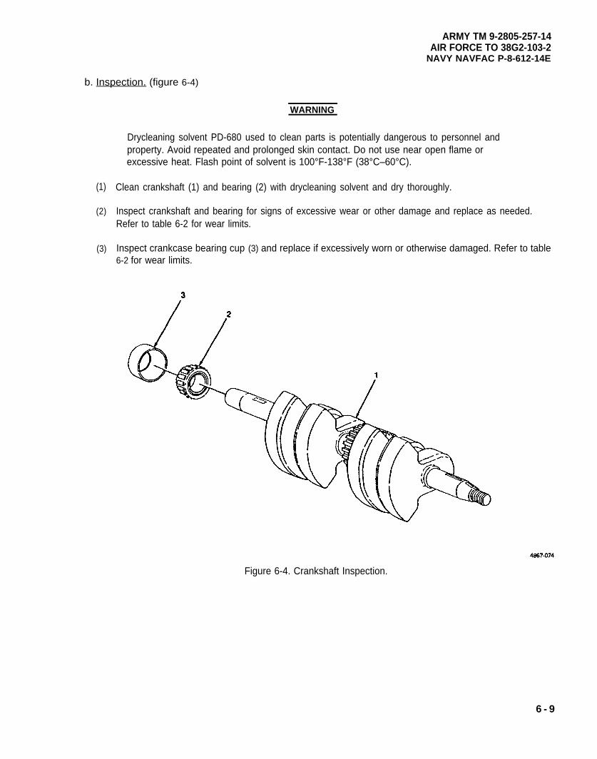
ARMY TM 9-2805-257-14AIR FORCE TO 38G2-103-2
NAVY NAVFAC P-8-612-14E
b. Inspection. (figure 6-4)
(1)
(2)
(3)
WARNING
Drycleaning solvent PD-680 used to clean parts is potentially dangerous to personnel andproperty. Avoid repeated and prolonged skin contact. Do not use near open flame orexcessive heat. Flash point of solvent is 100°F-138°F (38°C–60°C).
Clean crankshaft (1) and bearing (2) with drycleaning solvent and dry thoroughly.
Inspect crankshaft and bearing for signs of excessive wear or other damage and replace as needed.Refer to table 6-2 for wear limits.
Inspect crankcase bearing cup (3) and replace if excessively worn or otherwise damaged. Refer to table6-2 for wear limits.
Figure 6-4. Crankshaft Inspection.
6 - 9
ARMY TM 9-2805-257-14AIR FORCE TO 38G2-103-2NAVY NAVFAC P-8-612-14E
6-8. Crankshaft Assembly
c. Installation. (figure 6-5)
(cont).
Install bearing (2) and crankshaft (1) in crankcase (3) and aline timing marks on camshaft (4) andcrankshaft (1).
6-10
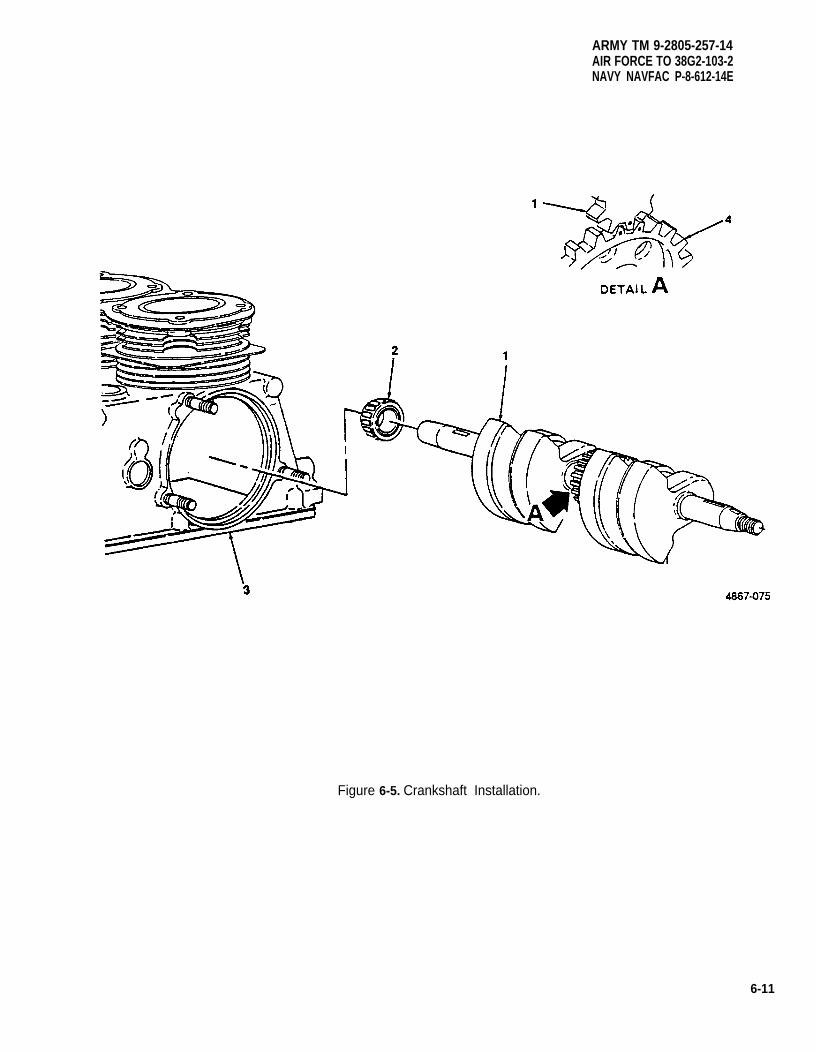
ARMY TM 9-2805-257-14AIR FORCE TO 38G2-103-2NAVY NAVFAC P-8-612-14E
Figure 6-5. Crankshaft Installation.
6-11
ARMY TM 9-2805-257-14AIR FORCE TO 38G2-103-2NAVY NAVFAC P-8-612-14E
6-9. Camshaft, Camshaft Axle, and Tappets.
This task covers: a. Removal b. Inspection c. Installation
INITIAL SETUP
Tools Equipment Condition
General Mechanic’s Tool Kit (Item 1, Appendix B) Crankshaft removed (para. 6-8).Puller, Kit Mechanical (NSN 5120-00-423-1596)
(Item 4, Appendix B)
Materials/Parts
Rags, Wiping (Item 6, Appendix D)Solvent, Drycleaning (Item 7, Appendix D)Seal, Camshaft Axle Plug (NSN 5330-00-797-4639)
a. Removal. (figure 6-6)
(1) Remove camshaft axle plug (1) and seal (2).
NOTE
To remove the camshaft axle install a long screw, with the same thread size as one of thescrews that secures the oil pan, into the camshaft axle and remove the axle.
(2) Remove camshaft axle (3).
(3) Remove camshaft (4) and valve tappets (5).
(4) Remove C clip (6) from camshaft axle (3).
b. Inspection. (figure 6-6)
WARNING
Drycleaning solvent PD-680 used to clean parts is potentially dangerous to personnel andproperty. Avoid repeated and prolonged skin contact. Do not use near open flame orexcessive heat. Flash point of solvent is 100°F-138°F (38°C-60°C).
(1) Clean camshaft (4), camshaft axle (3), and valve tappets (5) in dry cleaning solvent and dry thoroughly.
(2) Inspect all components for signs of excessive wear and replace items that are worm or otherwisedamaged. Refer to Table 6-2 for wear limits.
6-12
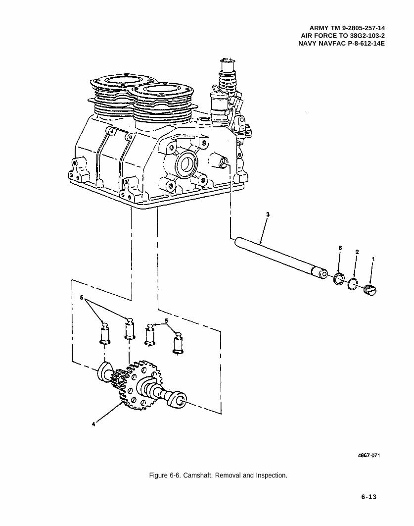
ARMY TM 9-2805-257-14AIR FORCE TO 38G2-103-2
NAVY NAVFAC P-8-612-14E
Figure 6-6. Camshaft, Removal and Inspection.
6-13
ARMY TM 9-2805-257-14AIR FORCE TO 38G2-103-2NAVY NAVFAC P-8-612-14E
6-9. Camshaft, Camshaft Axle, and Tappets (cont).
c. Installation. (figure 6-7)
(1) Install C clip (6) on axle (3).
(2) Install valve tappets (5).
(3) Install camshaft (4).
(4) Install camshaft axle (3).
(5) Install seal (2) and camshaft axle plug (1).
6-14
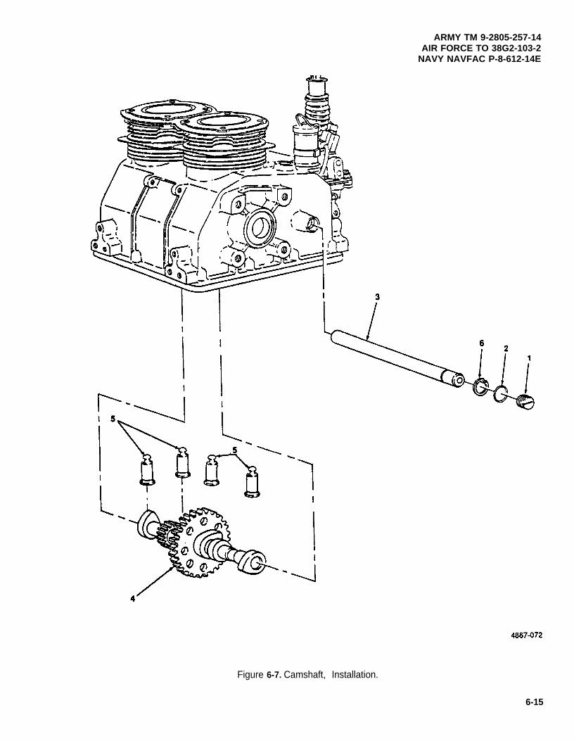
ARMY TM 9-2805-257-14AIR FORCE TO 38G2-103-2
NAVY NAVFAC P-8-612-14E
Figure 6-7. Camshaft, Installation.
6-15
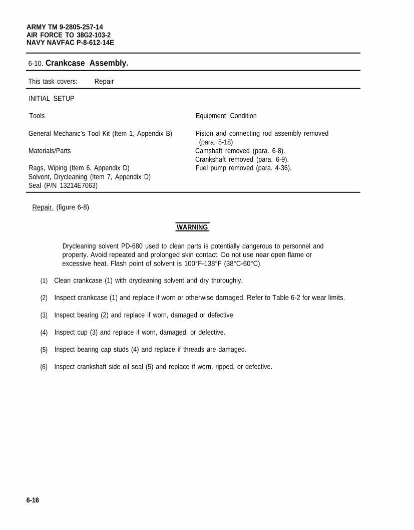
ARMY TM 9-2805-257-14AIR FORCE TO 38G2-103-2NAVY NAVFAC P-8-612-14E
6-10. Crankcase Assembly.
This task covers: Repair
INITIAL SETUP
Tools Equipment Condition
General Mechanic’s Tool Kit (Item 1, Appendix B) Piston and connecting rod assembly removed(para. 5-18)
Materials/Parts Camshaft removed (para. 6-8).Crankshaft removed (para. 6-9).
Rags, Wiping (Item 6, Appendix D) Fuel pump removed (para. 4-36).Solvent, Drycleaning (Item 7, Appendix D)Seal (P/N 13214E7063)
Repair. (figure 6-8)
(1)
(2)
(3)
(4)
(5)
(6)
WARNING
Drycleaning solvent PD-680 used to clean parts is potentially dangerous to personnel andproperty. Avoid repeated and prolonged skin contact. Do not use near open flame orexcessive heat. Flash point of solvent is 100°F-138°F (38°C-60°C).
Clean crankcase (1) with drycleaning solvent and dry thoroughly.
Inspect crankcase (1) and replace if worn or otherwise damaged. Refer to Table 6-2 for wear limits.
Inspect bearing (2) and replace if worn, damaged or defective.
Inspect cup (3) and replace if worn, damaged, or defective.
Inspect bearing cap studs (4) and replace if threads are damaged.
Inspect crankshaft side oil seal (5) and replace if worn, ripped, or defective.
6-16
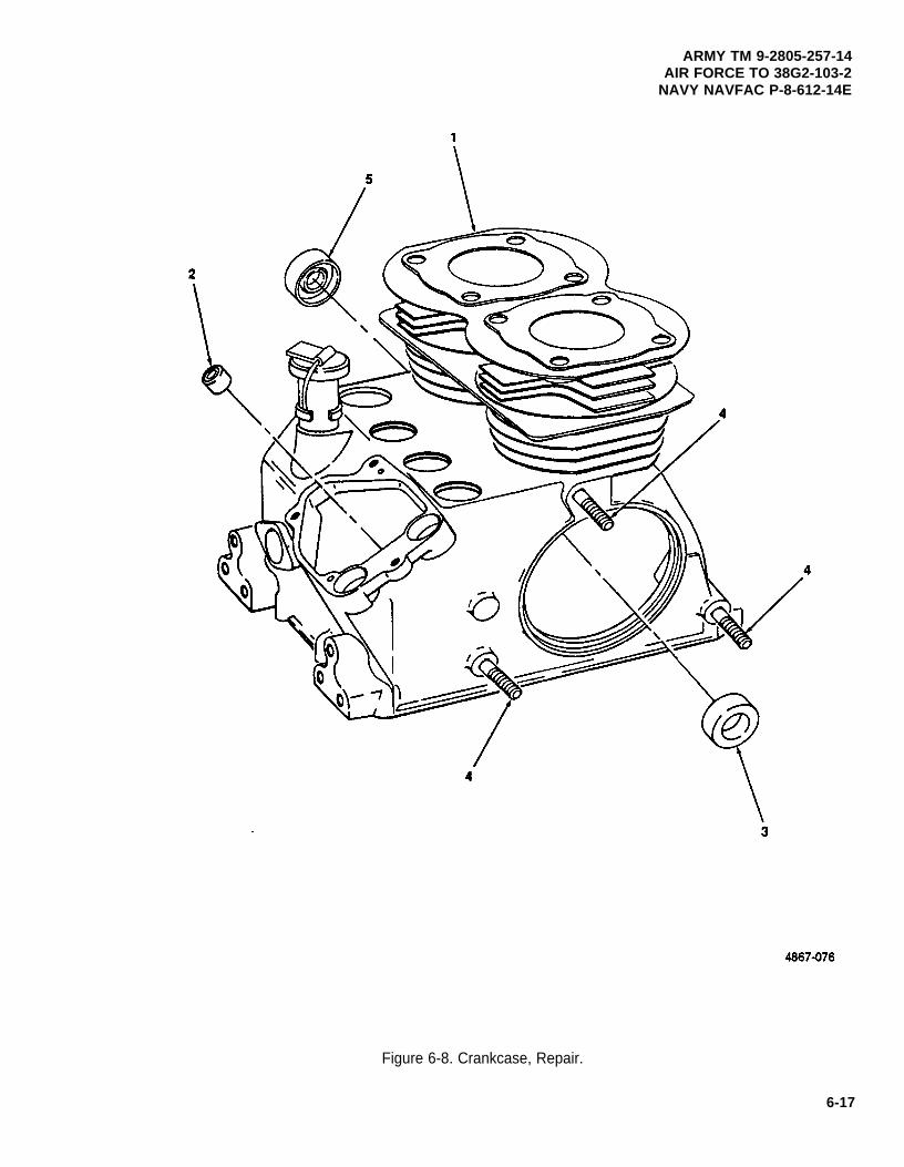
ARMY TM 9-2805-257-14AIR FORCE TO 38G2-103-2
NAVY NAVFAC P-8-612-14E
Figure 6-8. Crankcase, Repair.
6-17
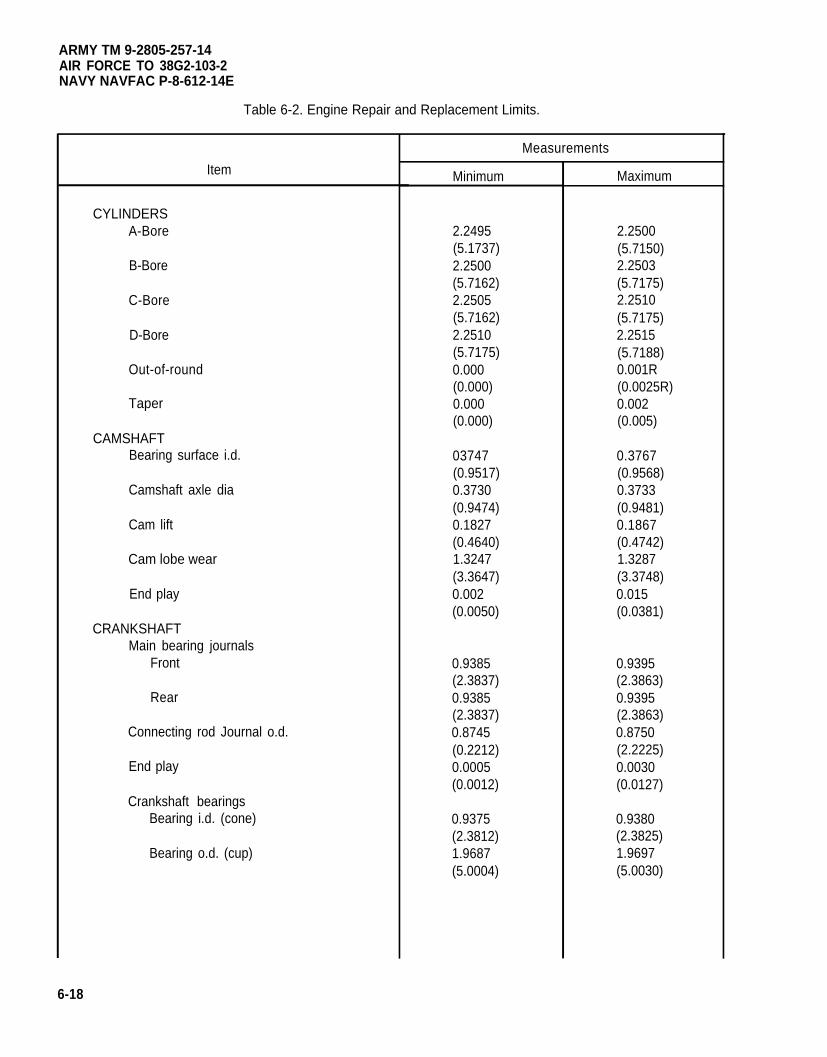
ARMY TM 9-2805-257-14AIR FORCE TO 38G2-103-2NAVY NAVFAC P-8-612-14E
Table 6-2. Engine Repair and Replacement Limits.
Item
CYLINDERSA-Bore
B-Bore
C-Bore
D-Bore
Out-of-round
Taper
CAMSHAFTBearing surface i.d.
Camshaft axle dia
Cam lift
Cam lobe wear
End play
CRANKSHAFTMain bearing journals
Front
Rear
Connecting rod Journal o.d.
End play
Crankshaft bearingsBearing i.d. (cone)
Bearing o.d. (cup)
Measurements
Minimum
2.2495(5.1737)2.2500(5.7162)2.2505(5.7162)2.2510(5.7175)0.000(0.000)0.000(0.000)
03747(0.9517)0.3730(0.9474)0.1827(0.4640)1.3247(3.3647)0.002(0.0050)
0.9385(2.3837)0.9385(2.3837)0.8745(0.2212)0.0005(0.0012)
0.9375(2.3812)1.9687(5.0004)
Maximum
2.2500(5.7150)2.2503(5.7175)2.2510(5.7175)2.2515(5.7188)0.001R(0.0025R)0.002(0.005)
0.3767(0.9568)0.3733(0.9481)0.1867(0.4742)1.3287(3.3748)0.015(0.0381)
0.9395(2.3863)0.9395(2.3863)0.8750(2.2225)0.0030(0.0127)
0.9380(2.3825)1.9697(5.0030)
6-18
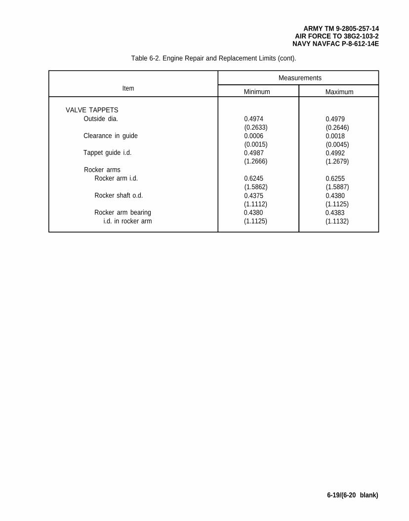
ARMY TM 9-2805-257-14AIR FORCE TO 38G2-103-2
NAVY NAVFAC P-8-612-14E
Table 6-2. Engine Repair and Replacement Limits (cont).
Measurements
Item Minimum Maximum
VALVE TAPPETSOutside dia. 0.4974 0.4979
(0.2633) (0.2646)Clearance in guide 0.0006 0.0018
(0.0015) (0.0045)Tappet guide i.d. 0.4987 0.4992
(1.2666) (1.2679)Rocker arms
Rocker arm i.d. 0.6245 0.6255(1.5862) (1.5887)
Rocker shaft o.d. 0.4375 0.4380(1.1112) (1.1125)
Rocker arm bearing 0.4380 0.4383i.d. in rocker arm (1.1125) (1.1132)
6-19/(6-20 blank)

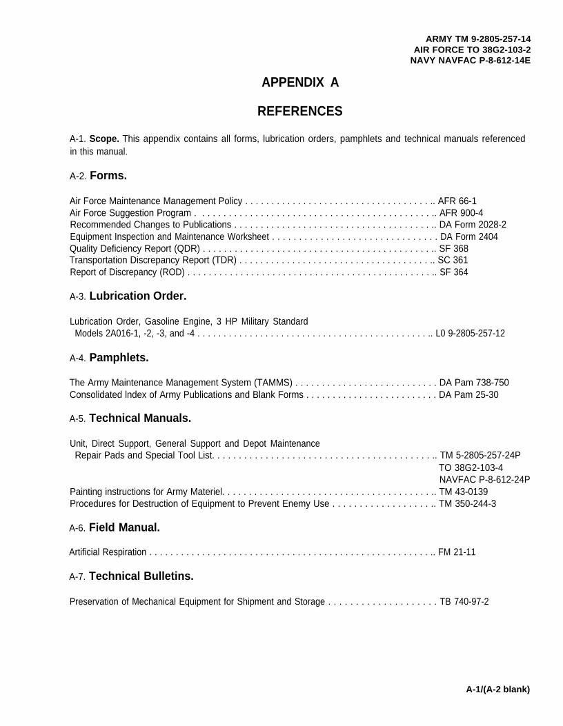
ARMY TM 9-2805-257-14AIR FORCE TO 38G2-103-2
NAVY NAVFAC P-8-612-14E
APPENDIX A
REFERENCES
A-1. Scope. This appendix contains all forms, lubrication orders, pamphlets and technical manuals referencedin this manual.
A-2. Forms.
Air Force Maintenance Management Policy . . . . . . . . . . . . . . . . . . . . . . . . . . . . . . . . . . . .. AFR 66-1Air Force Suggestion Program . . . . . . . . . . . . . . . . . . . . . . . . . . . . . . . . . . . . . . . . . . . . .. AFR 900-4Recommended Changes to Publications . . . . . . . . . . . . . . . . . . . . . . . . . . . . . . . . . . . . . .. DA Form 2028-2Equipment Inspection and Maintenance Worksheet . . . . . . . . . . . . . . . . . . . . . . . . . . . . . . . DA Form 2404Quality Deficiency Report (QDR) . . . . . . . . . . . . . . . . . . . . . . . . . . . . . . . . . . . . . . . . . . . .. SF 368Transportation Discrepancy Report (TDR) . . . . . . . . . . . . . . . . . . . . . . . . . . . . . . . . . . . . .. SC 361Report of Discrepancy (ROD) . . . . . . . . . . . . . . . . . . . . . . . . . . . . . . . . . . . . . . . . . . . . . . .. SF 364
A-3. Lubrication Order.
Lubrication Order, Gasoline Engine, 3 HP Military StandardModels 2A016-1, -2, -3, and -4 . . . . . . . . . . . . . . . . . . . . . . . . . . . . . . . . . . . . . . . . . . . . .. L0 9-2805-257-12
A-4. Pamphlets.
The Army Maintenance Management System (TAMMS) . . . . . . . . . . . . . . . . . . . . . . . . . . . DA Pam 738-750Consolidated lndex of Army Publications and Blank Forms . . . . . . . . . . . . . . . . . . . . . . . . . DA Pam 25-30
A-5. Technical Manuals.
Unit, Direct Support, General Support and Depot MaintenanceRepair Pads and Special Tool List. . . . . . . . . . . . . . . . . . . . . . . . . . . . . . . . . . . . . . . . . .. TM 5-2805-257-24P
TO 38G2-103-4NAVFAC P-8-612-24P
Painting instructions for Army Materiel. . . . . . . . . . . . . . . . . . . . . . . . . . . . . . . . . . . . . . . .. TM 43-0139Procedures for Destruction of Equipment to Prevent Enemy Use . . . . . . . . . . . . . . . . . . .. TM 350-244-3
A-6. Field Manual.
Artificial Respiration . . . . . . . . . . . . . . . . . . . . . . . . . . . . . . . . . . . . . . . . . . . . . . . . . . . . . .. FM 21-11
A-7. Technical Bulletins.
Preservation of Mechanical Equipment for Shipment and Storage . . . . . . . . . . . . . . . . . . . . TB 740-97-2
A-1/(A-2 blank)

ARMY TM 9-2805-257-14AIR FORCE TO 38G2-103-2
NAVY NAVFAC P-8-612-14E
APPENDIX B
MAINTENANCE ALLOCATION CHART
Section I. INTRODUCTION
B-1. Maintenance Allocation Chart (MAC). This MAC assigns maintenance functions in accordancewith the Three Level Maintenance Concept.
B-2. Use of the Maintenance Allocation Chart, Section Il.
a. The MAC assigns maintenance functions based on the following considerations:
(1) Skills available.
(2) Work time required.
(3) Tools and test equipment required and/or available.
b. If a lower level of maintenance identified in column (4) of the MAC cannot perform all tasks of a singlemaintenance function (e.g., test, repair), then the higher level that can perform other tasks of that function is alsoindicated.
c. Higher maintenance levels are automatically authorized to perform maintenance functions assigned to alower maintenance level.
d. Higher maintenance levels will perform the maintenance functions of lower maintenance levels whenrequired or directed by the Commander who has authority to direct such tasking.
e. Assignment of a maintenance function in the MAC does not carry automatic authorization to carry therelated spare or repair parts in stock. Information to requisition or secure parts will be as specified in theassociated RPSTL.
f. Normally, there will be no deviation from the assigned level of maintenance. However, in cases ofoperational necessity, maintenance functions assigned a higher level may, at the request of the lower level, beassigned to the lower level on a one-time basis, if specifically authorized by the maintenance officer of the higherlevel to which the function is assigned. In such a case, the special tools, equipment, etc., required by the lowerlevel to perform this function will be furnished by the higher level assigned the function. Also, transfer of a functionto a lower level does not relieve the higher level of responsibility for the function, so the higher level will providetechnical supervision and inspection of the function being performed at the lower level.
B-3. Maintenance Functions. Maintenance functions will be limited to and defined as follows:
a. Inspect. TO determine the serviceability of an item by comparing its physical, mechanical, and/or electricalcharacteristics with established standards through examination (e.g., by sight, sound, or feel).
b. Test. To verify serviceability and detect incipient failure by measuring the mechanical or electricalcharacteristics of an item and comparing those characteristics with prescribed standards.
B-1
ARMY TM 9-2805-257-14AIR FORCE TO 38G2-103-2NAVY NAVFAC P-8-612-14E
c. Service. Operations required periodically to keep an item in proper operating condition, i.e., to clean(includes decontaminate), to preserve, to drain, or to replenish fuel, lubricants, hydraulic fluids, or compressed air supplies.
d. Adjust. To maintain within prescribed limits, by bringing into proper or exact position, or by setting theoperating characteristics to the specified parameters.
e. Aline. To adjust specified variable elements of an item to bring about optimum or desired performance.
f. Calibrate. To determine and cause corrections to be made or to be adjusted on instruments or testmeasuring and diagnostic equipment used in precision measurement. Consists of comparison of two instruments,one of which is a certified standard of known accuracy, to detect and adjust any discrepancy inn the accuracy ofthe instrument being compared.
g. Install. The act of emplacing, seating, or fixing into position an item, part, or module (component assembly)in a manner to allow the proper functioning of an equipment or system.
h. Replace. The act of substituting a serviceable like type part, a subassembly, or module (component orassembly) for an unserviceable counterpart.
i. Repair. The application of maintenance services (inspect, test, service, adjust, aline, calibrate, or replace)or other maintenance actions (welding, grinding, riveting, straightening, facing, remachining, or resurfacing) torestore serviceability to an item by correcting specific damage, fault, malfunction, or failure in a part, subassembly,module (component or assembly), end item, or system.
j. Overhaul. That maintenance effort (service/action) necessary to restore an item to a completelyserviceable operational condition as prescribed by maintenance standards in appropriate technical publications(i.e., DMWR). Overhaul does not normally return an item to a like new condition.
k. Rebuild. Consists of those services/actions necessary for the restoration of unserviceable equipment to alike new condition in accordance with original manufacturing standards. Rebuild is the highest degree of materielmaintenance applied to Army equipment. The rebuild operation includes the act of returning to zero those agemeasurements (hours/miles, etc.) considered in classifying Army equipment/components.
B-4. Explanation of Columns in the MAC, Section II.
a. Column (1). Group Number. Column 1 lists functional group code numbers which are assigned to identifymaintenance significant components, assemblies, subassemblies, and modules to their next higher assembly.
b. Column (2). Component/Assembly. Column 2 contains the item names of components, assemblies,subassemblies, and modules for which group numbers (column 1) are assigned and for which maintenance isauthorized.
c. Column (3). Maintenace Function. Column 3 lists the functions to be performed on items listed in Column2. (Function definitions are contained in paragraph A-3.)
B-2
ARMY TM 9-2805-257-14AIR FORCE TO 38G2-103-2
NAVY NAVFAC P-8-612-14E
d. Column (4). Maintenance Level. The maintenance levels, Unit, Intermediate, and Depot, are allottedseparate subcolumns within column 4. Entry of a work time figure (such as 1.0, 0.2) in a subcolumn indicates thatthat level is authorized to perform the function listed in column 3, and the average time required to do the functionis the work time figure. If the number or complexity of tasks within a maintenance function varies from onemaintenance level to another, the applicable work time figure for each level will be entered for that function. Thework time figure represents the average time it takes to restore a component/assembly to a serviceable conditionunder a typical field operating environment.
e. Column (5). Tools and Equipment. Column 5 specifies, by code, common tool sets (not individual toolsfrom those sets), common TM DE, and special tools, TM DE, and support equipment required to perform adesignated function. The code in Column 5 keys to the listing in Section Ill of the MAC.
f. Column (6). Remarks. This column when applicable, contains a letter code with is keyed to an explanationof the code contained in Section IV of the MAC.
B-5. Explanation of Columns in the MAC, Section Ill.
a. Column (1). Tool or Test Equipment Reference Code. The tool or test equipment reference code correlateswith a code used in the MAC, Section II, Column 5.
b. Column (2). Maintenance Category. The lowest category of maintenance authorized to use the tool or testequipment.
c.
d.
e.
B-6.
a.
b.
Column (3). Nomenclature. Name or identification of the tool or test equipment.
Column (4). National/NATO Stock Number. The National stock number of the tool or test equipment.
Column (5). Tool Number. The manufacturer’s part number.
Explanation of Columns in the MAC, Section IV.
Column (1). Reference Code. The code recorded in column 6, Section Il.
Column (2). Remarks. This column lists information pertinent to the maintenance function being performedas indicated in the MAC, Section Il.
B-3
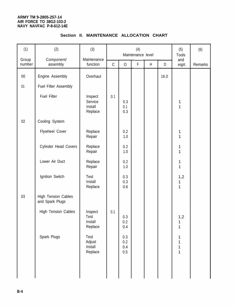
ARMY TM 9-2805-257-14AIR FORCE TO 38G2-103-2NAVY NAVFAC P-8-612-14E
Section Il. MAINTENANCE ALLOCATION CHART
(1)
Groupnumber
00
01
02
03
(2)
Component/assembly
Engine Assembly
Fuel Filter Assembly
Fuel Filter
Cooling System
Flywheel Cover
Cylinder Head Covers
Lower Air Duct
Ignition Switch
High Tension Cablesand Spark Plugs
High Tension Cables
Spark Plugs
(3)
Maintenancefunction
Overhaul
InspectServiceInstallReplace
ReplaceRepair
ReplaceRepair
ReplaceRepair
TestInstallReplace
InspectTestInstallReplace
TestAdjustInstallReplace
C
0.1
0.1
(4)Maintenance level
O
0.30.10.3
0.21.0
0.21.0
0.21.0
0.30.30.6
0.30.20.4
0.30.20.40.5
F H D
16.0
(5)Toolsandeqpt.
11
11
11
11
1,211
1,211
1111
(6)
Remarks
B-4
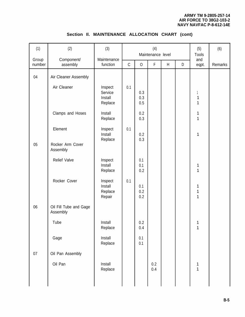
(1)
Groupnumber
04
05
06
07
ARMY TM 9-2805-257-14AIR FORCE TO 38G2-103-2
NAVY NAVFAC P-8-612-14E
Section Il. MAINTENANCE ALLOCATION CHART (cont)
(2)
Component/assembly
Air Cleaner Assembly
Air Cleaner
Clamps and Hoses
Element
Rocker Arm CoverAssembly
Relief Valve
Rocker Cover
Oil Fill Tube and GageAssembly
Tube
Gage
Oil Pan Assembly
Oil Pan
(3)
Maintenancefunction
InspectServiceInstallReplace
InstallReplace
InspectInstallReplace
InspectInstallReplace
InspectInstallReplaceRepair
InstallReplace
InstallReplace
InstallReplace
C
0.1
0.1
0.1
(4)Maintenance level
O
0.30.30.5
0.20.3
0.20.3
0.10.10.2
0.10.20.2
0.20.4
0.10.1
F
0.20.4
H D
(5)Toolsandeqpt.
111
11
1
11
111
11
11
(6)
Remarks
B-5
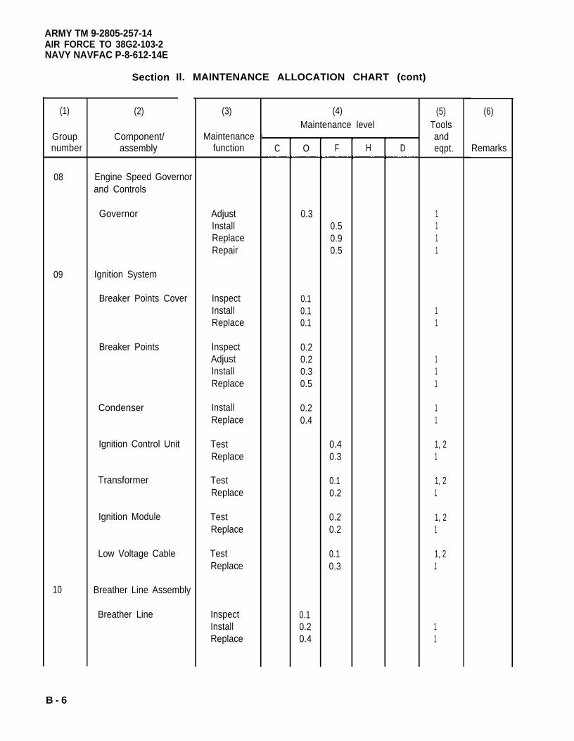
ARMY TM 9-2805-257-14AIR FORCE TO 38G2-103-2NAVY NAVFAC P-8-612-14E
(1)
Groupnumber
08
09
10
Section Il. MAINTENANCE ALLOCATION CHART (cont)
(2)
Component/assembly
Engine Speed Governorand Controls
Governor
Ignition System
Breaker Points Cover
Breaker Points
Condenser
Ignition Control Unit
Transformer
Ignition Module
Low Voltage Cable
Breather Line Assembly
Breather Line
(3)
Maintenancefunction
AdjustInstallReplaceRepair
InspectInstallReplace
InspectAdjustInstallReplace
InstallReplace
TestReplace
TestReplace
TestReplace
TestReplace
InspectInstallReplace
C
(4)Maintenance level
O
0.3
0.10.10.1
0.20.20.30.5
0.20.4
0.10.20.4
F
0.50.90.5
0.40.3
0.10.2
0.20.2
0.10.3
H D
(5)Toolsandeqpt.
1111
11
111
11
1, 21
1, 21
1, 21
1, 21
11
(6)
Remarks
B - 6
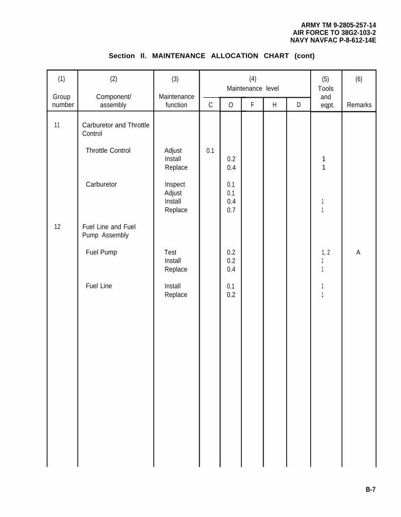
(1)
Groupnumber
11
12
ARMY TM 9-2805-257-14AIR FORCE TO 38G2-103-2
NAVY NAVFAC P-8-612-14E
Section Il. MAINTENANCE ALLOCATION CHART (cont)
(2)
Component/assembly
Carburetor and ThrottleControl
Throttle Control
Carburetor
Fuel Line and FuelPump Assembly
Fuel Pump
Fuel Line
(3)
Maintenancefunction
AdjustInstallReplace
InspectAdjustInstallReplace
TestInstallReplace
InstallReplace
C
0.1
(4)Maintenance level
O
0.20.4
0.10.10.40.7
0.20.20.4
0.10.2
F H D
(5)Toolsandeqpt.
11
11
1, 211
11
(6)
Remarks
A
B-7
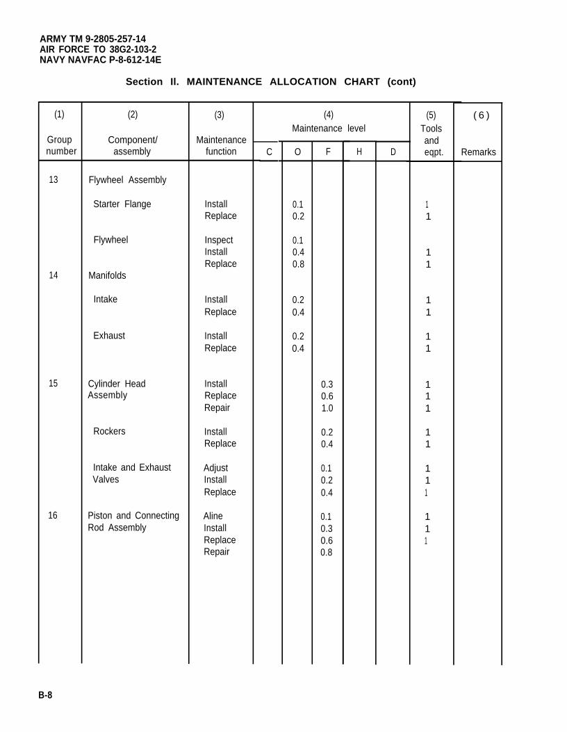
ARMY TM 9-2805-257-14AIR FORCE TO 38G2-103-2NAVY NAVFAC P-8-612-14E
(1)
Groupnumber
13
14
15
16
Section Il. MAINTENANCE ALLOCATION CHART (cont)
(2)
Component/assembly
Flywheel Assembly
Starter Flange
Flywheel
Manifolds
Intake
Exhaust
Cylinder HeadAssembly
Rockers
Intake and ExhaustValves
Piston and ConnectingRod Assembly
(3)
Maintenancefunction
InstallReplace
InspectInstallReplace
InstallReplace
InstallReplace
InstallReplaceRepair
InstallReplace
AdjustInstallReplace
AlineInstallReplaceRepair
C
(4)Maintenance level
O
0.10.2
0.10.40.8
0.20.4
0.20.4
F
0.30.61.0
0.20.4
0.10.20.4
0.10.30.60.8
H D
(5)Toolsandeqpt.
11
11
11
11
111
11
111
111
( 6 )
Remarks
B-8
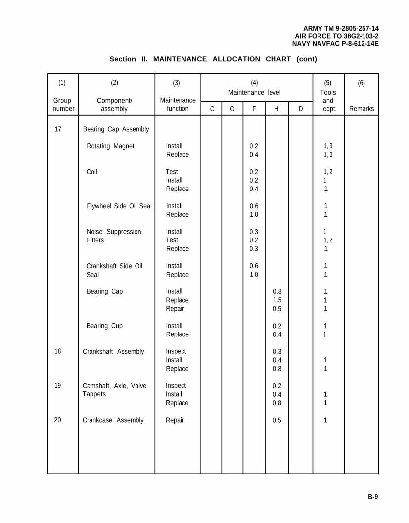
ARMY TM 9-2805-257-14AIR FORCE TO 38G2-103-2
NAVY NAVFAC P-8-612-14E
Section II. MAINTENANCE ALLOCATION CHART (cont)
(1) (2) (3) (4) (5) (6)Maintenance level Tools
Group Component/ Maintenance andnumber assembly function C O F H D eqpt. Remarks
17 Bearing Cap Assembly
Rotating Magnet Install 0.2 1, 3Replace 0.4 1, 3
Coil Test 0.2 1, 2Install 0.2 1Replace 0.4 1
Flywheel Side Oil Seal Install 0.6 1Replace 1.0 1
Noise Suppression Install 0.3 1Fitters Test 0.2 1, 2
Replace 0.3 1
Crankshaft Side Oil Install 0.6 1Seal Replace 1.0 1
Bearing Cap Install 0.8 1Replace 1.5 1Repair 0.5 1
Bearing Cup Install 0.2 1Replace 0.4 1
18 Crankshaft Assembly Inspect 0.3Install 0.4 1Replace 0.8 1
19 Camshaft, Axle, Valve Inspect 0.2Tappets Install 0.4 1
Replace 0.8 1
20 Crankcase Assembly Repair 0.5 1
B-9
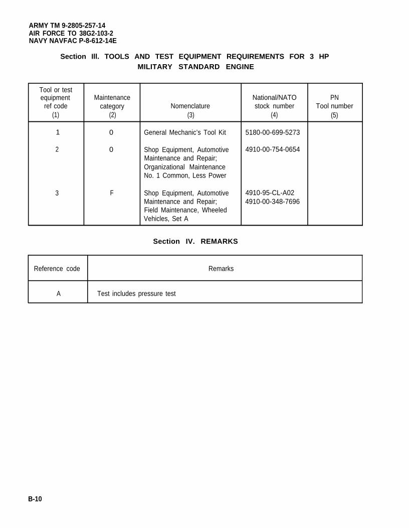
ARMY TM 9-2805-257-14AIR FORCE TO 38G2-103-2NAVY NAVFAC P-8-612-14E
Section Ill. TOOLS AND TEST EQUIPMENT REQUIREMENTS FOR 3 HPMILITARY STANDARD ENGINE
Tool or testequipment Maintenance National/NATO PN
ref code category Nomenclature stock number Tool number(1) (2) (3) (4) (5)
1 0 General Mechanic’s Tool Kit 5180-00-699-5273
2 0 Shop Equipment, Automotive 4910-00-754-0654Maintenance and Repair;Organizational MaintenanceNo. 1 Common, Less Power
3 F Shop Equipment, Automotive 4910-95-CL-A02Maintenance and Repair; 4910-00-348-7696Field Maintenance, WheeledVehicles, Set A
Section IV. REMARKS
Reference code Remarks
A Test includes pressure test
B-10
ARMY TM 9-2805-257-14AIR FORCE TO 38G2-103-2
NAVY NAVFAC P-8-612-14E
APPENDIX C
COMPONENTS OF END ITEM AND BASIC ISSUE ITEMS LISTS
Section I.
C-1. Scope.
INTRODUCTION
This appendix lists components of end item and basic issue items for the 3 HP Military Standard Engine to helpyou inventory items required for safe and efficient operation.
C-2. General.
The Components of End Item and Basic Issue Items Lists are divided into the following sections.
a. Section II. Components of End Item. This listing is for informational purposes only, and is not authority torequisition replacements. The items are part of the end item, but are removed and separately packaged fortransportation or shipment. As part of the end item, these items must be with the end item whenever it is issuedor transferred between properly accounts. Illustrations are furnished to assist you in identifying the items.
b. Section III. Basic Issue Items. These are the minimum essential items required to place the 3 HP Militarystandard engine in operation. The illustrations will assist you with hard-to-identify items. This manual is yourauthority to request/requisition replacement Bll, based on TO E/MTOE authorization of the end item.
C-3. Explanation of Columns.
The following provides an explanation of columns found in the tabular listings:
a. Column (1), Illustration Number (Illus Number). This column indicates the number of the illustration inwhich the item is shown.
b. Column (2). National Stock Number. Indicates the National Stock Number assigned to the item and will beused for requisitioning purposes.
c. Column (3). Description. Indicates the Federal item name, and, if required, a minimum description toidentify and locate the item. The last line for each item indicates the FSCM (in parentheses) followed by the partnumber.
d. Column (4). Unit of Measure (U/M). Indicates the measure used in performing the actual operational/maintenance function. This measure is expressed by a two-character alphabetical abbreviation (e.g., ea, in., pr).
e. Column (5). Quantity Required (QTY RQR). Indicates the quantity of the item authorized to be used with/onthe equipment.
C-1
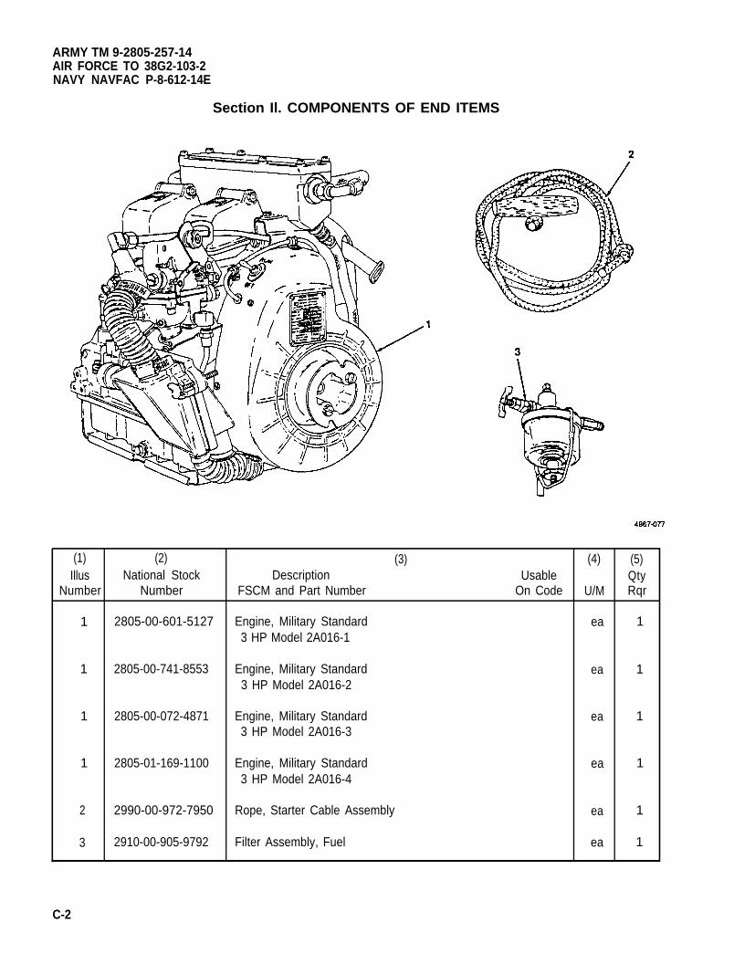
ARMY TM 9-2805-257-14AIR FORCE TO 38G2-103-2NAVY NAVFAC P-8-612-14E
Section Il. COMPONENTS OF END ITEMS
(1) (2) (3) (4) (5)Illus National Stock Description Usable Qty
Number Number FSCM and Part Number On Code U/M Rqr
1 2805-00-601-5127 Engine, Military Standard ea 13 HP Model 2A016-1
1 2805-00-741-8553 Engine, Military Standard ea 13 HP Model 2A016-2
1 2805-00-072-4871 Engine, Military Standard ea 13 HP Model 2A016-3
1 2805-01-169-1100 Engine, Military Standard ea 13 HP Model 2A016-4
2 2990-00-972-7950 Rope, Starter Cable Assembly ea 1
3 2910-00-905-9792 Filter Assembly, Fuel ea 1
C-2
ARMY TM 9-2805-257-14AIR FORCE TO 38G2-103-2
NAVY NAVFAC P-8-612-14E
Section Ill. BASIC ISSUE ITEMS
Not Applicable
C-3/(C-4 blank)

ARMY TM 9-2805-257-14AIR FORCE TO 38G2-103-2
NAVY NAVFAC P-8-612-14E
APPENDIX D
EXPENDABLE/DURABLE SUPPLIES MATERIALS LIST
Section I. INTRODUCTION
D-1. Scope. This listing is for informational purposes only and is not authority to requisition the listed items.These items are authorized to you by CTA 50-970, Expendable/Durable Items (except medical, class V, repairparts, and heraldic items).
D-2. Explanation of Columns.
a. Column (1) - Item Number. This number is assigned to the entry in the listing and is referenced in thenarrative instructions to identify the material (e.g., ”Use cleaning compound, item 5, appendix C)”.
b. Colunm (2) - Level. This column identifies the lowest level of maintenance that requires the listed item.
C - Operator/CrewO - Organizational MaintenanceF - Direct Support MaintenanceH - General Support Maintenance
c. Column (3) - National Stock Number.request or requisition the item.
This is the National stock number assigned to the item; use it to
d. Column (4) - Description. Indicates the Federal item name, and, if required, a description to identify theitem. The last line for each item indicates the Federal Supply code for Manufacturer (FSCM) in parenthesesfollowed by the part number.
d. Column (5) - Unit of Measure (U/M). Indicates the measure used in performing the actual maintenancefunction. This measure is expressed by a two-character alphabetical abbreviation (e.g., EA, IN., PR). If the unit ofmeasure differs from the unit of issue, requisition the lowest unit of issue that will satisfy your requirements.
D-1
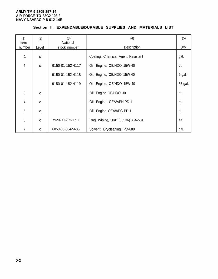
ARMY TM 9-2805-257-14AIR FORCE TO 38G2-103-2NAVY NAVFAC P-8-612-14E
Section Il. EXPENDABLE/DURABLE SUPPLIES AND MATERIALS LIST
(1) (2) (3) (4) (5)Item National
number Level stock number Description U/M
1 c Coating, Chemical Agent Resistant gal.
2 c 9150-01-152-4117 Oil, Engine, OE/HDO 15W-40 qt.
9150-01-152-4118 Oil, Engine, OE/HDO 15W-40 5 gal.
9150-01-152-4119 Oil, Engine, OE/HDO 15W-40 55 gal.
3 c Oil, Engine OE/HDO 30 qt.
4 c Oil, Engine, OEA/APH-PD-1 qt.
5 c Oil, Engine OEA/APG-PD-1 qt.
6 c 7920-00-205-1711 Rag, Wiping, 50/B (58536) A-A-531 ea
7 c 6850-00-664-5685 Solvent, Drycleaning, PD-680 gal.
D-2
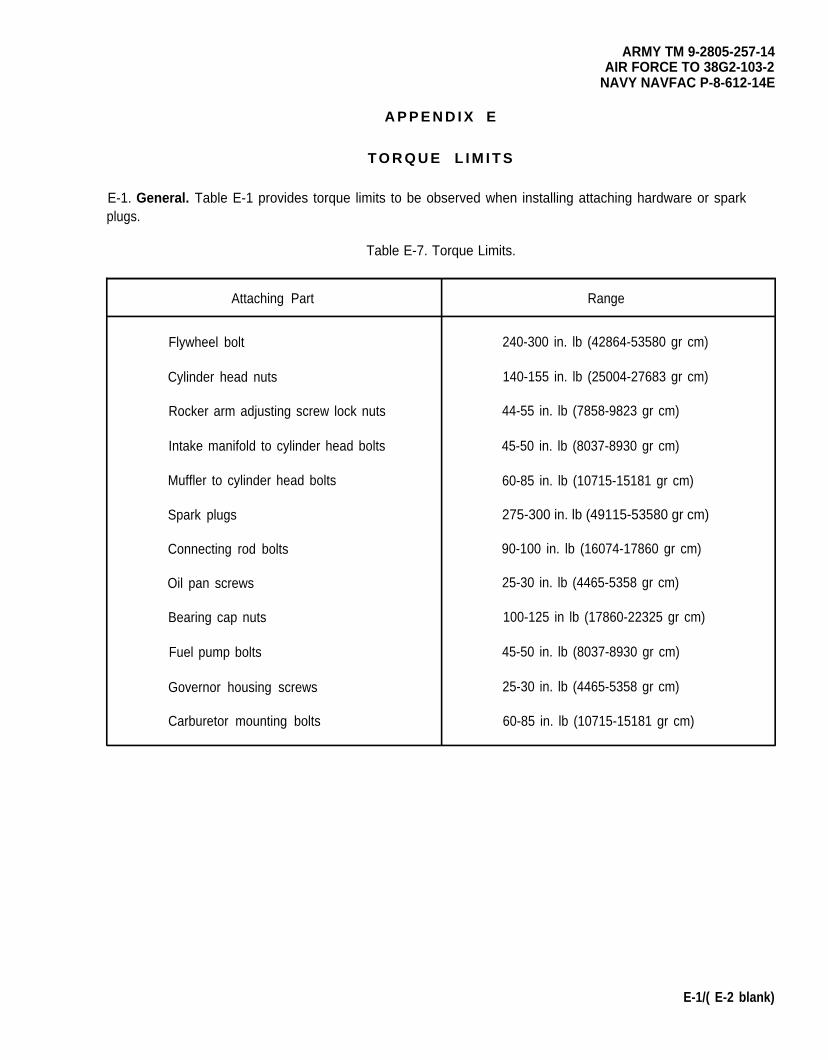
ARMY TM 9-2805-257-14AIR FORCE TO 38G2-103-2
NAVY NAVFAC P-8-612-14E
A P P E N D I X E
T O R Q U E L I M I T S
E-1. General. Table E-1 provides torque limits to be observed when installing attaching hardware or sparkplugs.
Table E-7. Torque Limits.
Attaching Part Range
Flywheel bolt 240-300 in. lb (42864-53580 gr cm)
Cylinder head nuts 140-155 in. lb (25004-27683 gr cm)
Rocker arm adjusting screw lock nuts 44-55 in. lb (7858-9823 gr cm)
Intake manifold to cylinder head bolts 45-50 in. lb (8037-8930 gr cm)
Muffler to cylinder head bolts 60-85 in. lb (10715-15181 gr cm)
Spark plugs 275-300 in. lb (49115-53580 gr cm)
Connecting rod bolts 90-100 in. lb (16074-17860 gr cm)
Oil pan screws 25-30 in. lb (4465-5358 gr cm)
Bearing cap nuts 100-125 in lb (17860-22325 gr cm)
Fuel pump bolts 45-50 in. lb (8037-8930 gr cm)
Governor housing screws 25-30 in. lb (4465-5358 gr cm)
Carburetor mounting bolts 60-85 in. lb (10715-15181 gr cm)
E-1/( E-2 blank)
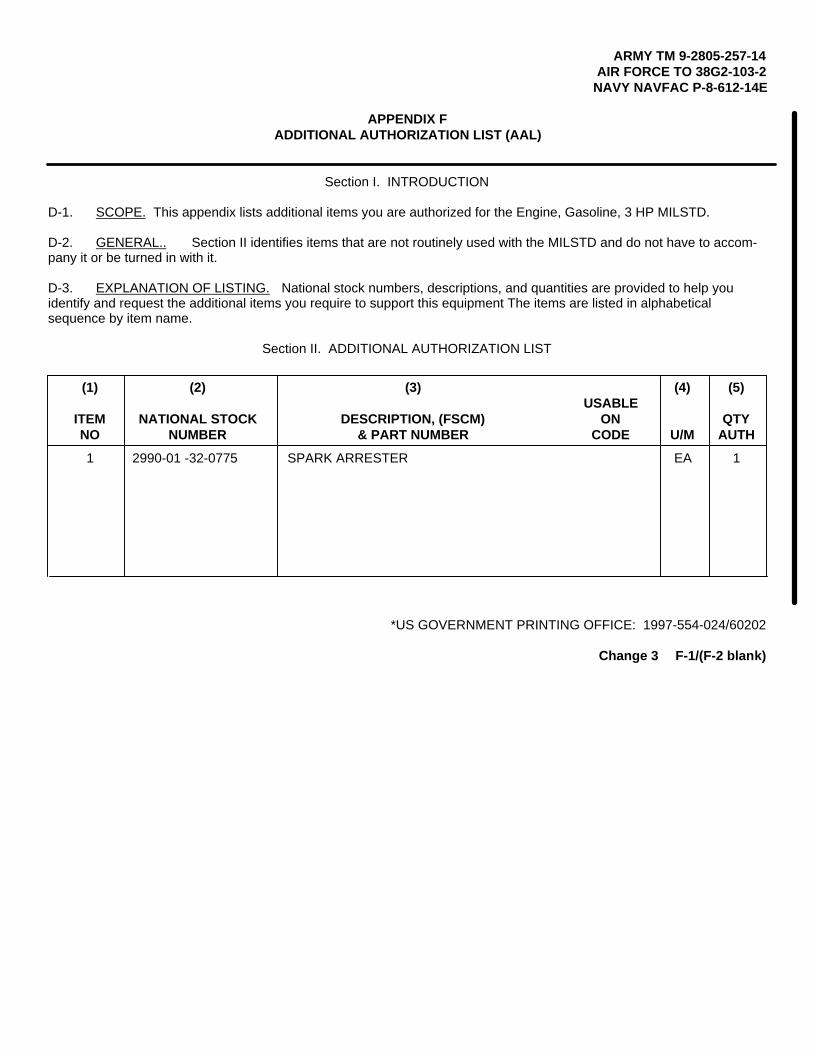
ARMY TM 9-2805-257-14AIR FORCE TO 38G2-103-2
NAVY NAVFAC P-8-612-14E
APPENDIX FADDITIONAL AUTHORIZATION LIST (AAL)
Section I. INTRODUCTION
D-1. SCOPE. This appendix lists additional items you are authorized for the Engine, Gasoline, 3 HP MILSTD.
D-2. GENERAL.. Section II identifies items that are not routinely used with the MILSTD and do not have to accom-pany it or be turned in with it.
D-3. EXPLANATION OF LISTING. National stock numbers, descriptions, and quantities are provided to help youidentify and request the additional items you require to support this equipment The items are listed in alphabeticalsequence by item name.
Section II. ADDITIONAL AUTHORIZATION LIST
(1) (2) (3) (4) (5)USABLE
ITEM NATIONAL STOCK DESCRIPTION, (FSCM) ON QTYNO NUMBER & PART NUMBER CODE U/M AUTH
1 2990-01 -32-0775 SPARK ARRESTER EA 1
*US GOVERNMENT PRINTING OFFICE: 1997-554-024/60202
Change 3 F-1/(F-2 blank)
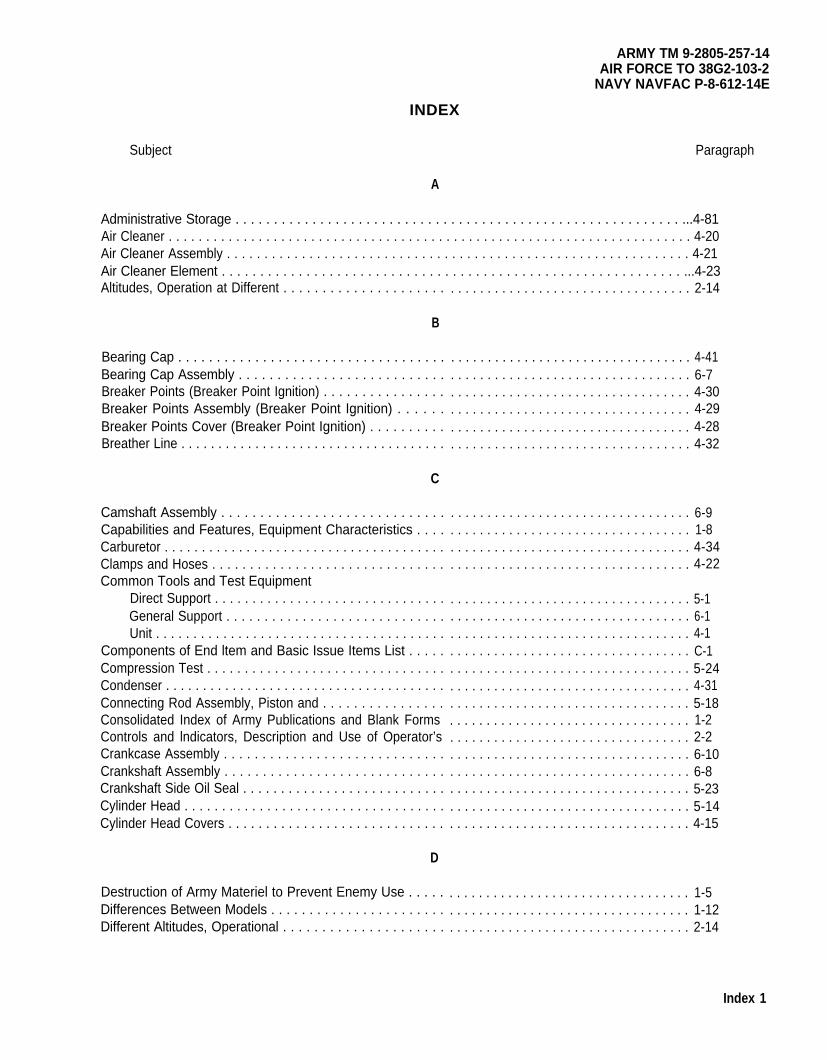
ARMY TM 9-2805-257-14AIR FORCE TO 38G2-103-2
NAVY NAVFAC P-8-612-14E
INDEX
Subject Paragraph
A
Administrative Storage . . . . . . . . . . . . . . . . . . . . . . . . . . . . . . . . . . . . . . . . . . . . . . . . . . . . . . . . . . ...4-81Air Cleaner . . . . . . . . . . . . . . . . . . . . . . . . . . . . . . . . . . . . . . . . . . . . . . . . . . . . . . . . . . . . . . . . . . . . . . 4-20Air Cleaner Assembly . . . . . . . . . . . . . . . . . . . . . . . . . . . . . . . . . . . . . . . . . . . . . . . . . . . . . . . . . . . . . . 4-21Air Cleaner Element . . . . . . . . . . . . . . . . . . . . . . . . . . . . . . . . . . . . . . . . . . . . . . . . . . . . . . . . . . . . ...4-23Altitudes, Operation at Different . . . . . . . . . . . . . . . . . . . . .
B
Bearing Cap . . . . . . . . . . . . . . . . . . . . . . . . . . . . . . . . . . .Bearing Cap Assembly . . . . . . . . . . . . . . . . . . . . . . . . . . .Breaker Points (Breaker Point Ignition) . . . . . . . . . . . . . . . .Breaker Points Assembly (Breaker Point Ignition) . . . . . .Breaker Points Cover (Breaker Point Ignition) . . . . . . . . . .Breather Line . . . . . . . . . . . . . . . . . . . . . . . . . . . . . . . . . . . .
C
Camshaft Assembly . . . . . . . . . . . . . . . . . . . . . . . . . . . . .Capabilities and Features, Equipment Characteristics . . . .Carburetor . . . . . . . . . . . . . . . . . . . . . . . . . . . . . . . . . . . . . .Clamps and Hoses . . . . . . . . . . . . . . . . . . . . . . . . . . . . . . .Common Tools and Test Equipment
Direct Support . . . . . . . . . . . . . . . . . . . . . . . . . . . . . . .General Support . . . . . . . . . . . . . . . . . . . . . . . . . . . . .Unit . . . . . . . . . . . . . . . . . . . . . . . . . . . . . . . . . . . . . . .
Components of End ltem and Basic Issue Items List . . . . .Compression Test . . . . . . . . . . . . . . . . . . . . . . . . . . . . . . . .Condenser . . . . . . . . . . . . . . . . . . . . . . . . . . . . . . . . . . . . . .Connecting Rod Assembly, Piston and . . . . . . . . . . . . . . . .Consolidated Index of Army Publications and Blank FormsControls and lndicators, Description and Use of Operator’sCrankcase Assembly . . . . . . . . . . . . . . . . . . . . . . . . . . . . .Crankshaft Assembly . . . . . . . . . . . . . . . . . . . . . . . . . . . . .Crankshaft Side Oil Seal . . . . . . . . . . . . . . . . . . . . . . . . . . .Cylinder Head . . . . . . . . . . . . . . . . . . . . . . . . . . . . . . . . . . .Cylinder Head Covers . . . . . . . . . . . . . . . . . . . . . . . . . . . . .
D
Destruction of Army Materiel to Prevent Enemy Use . . . . .Differences Between Models . . . . . . . . . . . . . . . . . . . . . . .Different Altitudes, Operational . . . . . . . . . . . . . . . . . . . . .
. . . . . . . . . . . . . . . . . . . . . . . . . . . . . . . . . 2-14
. . . . . . . . . . . . . . . . . . . . . . . . . . . . . . . . . 4-41
. . . . . . . . . . . . . . . . . . . . . . . . . . . . . . . . . 6-7
. . . . . . . . . . . . . . . . . . . . . . . . . . . . . . . . . 4-30
. . . . . . . . . . . . . . . . . . . . . . . . . . . . . . . . . 4-29
. . . . . . . . . . . . . . . . . . . . . . . . . . . . . . . . . 4-28
. . . . . . . . . . . . . . . . . . . . . . . . . . . . . . . . . 4-32
. . . . . . . . . . . . . . . . . . . . . . . . . . . . . . . . . 6-9
. . . . . . . . . . . . . . . . . . . . . . . . . . . . . . . . . 1-8
. . . . . . . . . . . . . . . . . . . . . . . . . . . . . . . . . 4-34
. . . . . . . . . . . . . . . . . . . . . . . . . . . . . . . . . 4-22
. . . . . . . . . . . . . . . . . . . . . . . . . . . . . . . . . 5-1
. . . . . . . . . . . . . . . . . . . . . . . . . . . . . . . . . 6-1
. . . . . . . . . . . . . . . . . . . . . . . . . . . . . . . . . 4-1
. . . . . . . . . . . . . . . . . . . . . . . . . . . . . . . . . C-1
. . . . . . . . . . . . . . . . . . . . . . . . . . . . . . . . . 5-24
. . . . . . . . . . . . . . . . . . . . . . . . . . . . . . . . . 4-31
. . . . . . . . . . . . . . . . . . . . . . . . . . . . . . . . . 5-18
. . . . . . . . . . . . . . . . . . . . . . . . . . . . . . . . . 1-2
. . . . . . . . . . . . . . . . . . . . . . . . . . . . . . . . . 2-2
. . . . . . . . . . . . . . . . . . . . . . . . . . . . . . . . . 6-10
. . . . . . . . . . . . . . . . . . . . . . . . . . . . . . . . . 6-8
. . . . . . . . . . . . . . . . . . . . . . . . . . . . . . . . . 5-23
. . . . . . . . . . . . . . . . . . . . . . . . . . . . . . . . . 5-14
. . . . . . . . . . . . . . . . . . . . . . . . . . . . . . . . . 4-15
. . . . . . . . . . . . . . . . . . . . . . . . . . . . . . . . . 1-5
. . . . . . . . . . . . . . . . . . . . . . . . . . . . . . . . . 1-12
. . . . . . . . . . . . . . . . . . . . . . . . . . . . . . . . . 2-14
Index 1
ARMY TM 9-2805-257-14AIR FORCE TO 38G2-103-2NAVY NAVFAC P-8-612-14E
Subject
INDEX (cont)
D (cont)Paragraph
Direct Support Maintenance ProceduresCoil . . . . . . . . . . . . . . . . . . . . . . . . . . . . . . . . . . . . . . . . . . . . . . . . . . . . . . . . . . . . . . . . . . . . . ...5-20Compression Test . . . . . . . . . . . . . . . . . . . . . . . . . . . . . . . . . . . . . . . . . . . . . . . . . . . . . . . . . . ...5-24Crankshaft Side or Seal . . . . . . . . . . . . . . . . . . . . . . . . . . . . . . . . . . . . . . . . . . . . . . . . . . . . ...5-23Cylinder Head . . . . . . . . . . . . . . . . . . . . . . . . . . . . . . . . . . . . . . . . . . . . . . . . . . . . . . . . . . . . . ...5-14Flywheel Side Oil Seal . . . . . . . . . . . . . . . . . . . . . . . . . . . . . . . . . . . . . . . . . . . . . . . . . . . . . . . . .5-21Governor Assembly . . . . . . . . . . . . . . . . . . . . . . . . . . . . . . . . . . . . . . . . . . . . . . . . . . . . . . . . . ...5-8Ignition Control Unit (Breakerless Ignition) . . . . . . . . . . . . . . . . . . . . . . . . . . . . . . . . . . . . . . . ...5-10Ignition Module (Breakerless Ignition) . . . . . . . . . . . . . . . . . . . . . . . . . . . . . . . . . . . . . . . . . . . ...5-12Ignition Timing (Breaker Point Ignition) . . . . . . . . . . . . . . . . . . . . . . . . . . . . . . . . . . . . . . . . . . ...5-9lntakeand Exhaust Valves . . . . . . . . . . . . . . . . . . . . . . . . . . . . . . . . . . . . . . . . . . . . . . . . . . . ...5-17Low Voltage Cable (Breakerless Ignition) . . . . . . . . . . . . . . . . . . . . . . . . . . . . . . . . . . . . . . . . ...5-13Noise Suppression Filter(Breaker Point Ignition) . . . . . . . . . . . . . . . . . . . . . . . . . . . . . . . . . . ...5-22Oil Pan . . . . . . . . . . . . . . . . . . . . . . . . . . . . . . . . . . . . . . . . . . . . . . . . . . . . . . . . . . . . . . . . . ...5-7Piston and Connecting Rod Assembly . . . . . . . . . . . . . . . . . . . . . . . . . . . . . . . . . . . . . . . . . . ...5-18Rockers . . . . . . . . . . . . . . . . . . . . . . . . . . . . . . . . . . . . . . . . . . . . . . . . . . . . . . . . . . . . . . . . . . ...5-15Rotating Magnet . . . . . . . . . . . . . . . . . . . . . . . . . . . . . . . . . . . . . . . . . . . . . . . . . . . . . . . . . . . ...5-19Transformer (Breakerless Ignition) . . . . . . . . . . . . . . . . . . . . . . . . . . . . . . . . . . . . . . . . . . . . . ...5-11Valve Adjustment . . . . . . . . . . . . . . . . . . . . . . . . . . . . . . . . . . . . . . . . . . . . . . . . . . . . . . . . . . . ..5-16
Direct Support Troubleshooting Procedures . . . . . . . . . . . . . . . . . . . . . . . . . . . . . . . . . . . . . . . . . . ...5-5Dusty orSandy Areas, Operation in . . . . . . . . . . . . . . . . . . . . . . . . . . . . . . . . . . . . . . . . . . . . . . . . . . . 2-11
E
Element, Air Cleaner . . . . . . . . . . . . . . . . . . . . . . . . . . . . . . . . . . . . . . . . . . . . . . . . . . . . . . . . . . . . ...4-23Equipment Characteristics,Capabilities and Features . . . . . . . . . . . . . . . . . . . . . . . . . . . . . . . . . . ...1-8Equipment Data . . . . . . . . . . . . . . . . . . . . . . . . . . . . . . . . . . . . . . . . . . . . . . . . . . . . . . . . . . . . . . . ...1-11Equipment Improvement Recommendations (EIR), Reporting . . . . . . . . . . . . . . . . . . . . . . . . . . . . ...1-4Exhaust Manifold . . . . . . . . . . . . . . . . . . . . . . . . . . . . . . . . . . . . . . . . . . . . . . . . . . . . . . . . . . . . . . . ...4-40Exhaust Valves, lntake and . . . . . . . . . . . . . . . . . . . . . . . . . . . . . . . . . . . . . . . . . . . . . . . . . . . . . . . ...5-17Expendables/DurablesSupplies Materiels List . . . . . . . . . . . . . . . . . . . . . . . . . . . . . . . . . . . . . . . . . ..D-1Extreme Cold, Operation in . . . . . . . . . . . . . . . . . . . . . . . . . . . . . . . . . . . . . . . . . . . . . . . . . . . . . . . . . . 2-15Extreme Heat, Operation in. . . . . . . . . . . . . . . . . . . . . . . . . . . . . . . . . . . . . . . . . . . . . . . . . . . . . . . . ..2-13
F
Fiiter, Noise Suppression . . . . . . . . . . . . . . . . . . . . . . . . . . . . . . . . . . . . . . . . . . . . . . . . . . . . . . . . ...5-22Flywheel . . . . . . . . . . . . . . . . . . . . . . . . . . . . . . . . . . . . . . . . . . . . . . . . . . . . . . . . . . . . . . . . . . . . . ...4-38Flywheel Cover . . . . . . . . . . . . . . . . . . . . . . . . . . . . . . . . . . . . . . . . . . . . . . . . . . . . . . . . . . . . . . . . ...4-14Flywheel Side Oil Seal . . . . . . . . . . . . . . . . . . . . . . . . . . . . . . . . . . . . . . . . . . . . . . . . . . . . . . . . . . ...5-21Fuel Filter Assembly . . . . . . . . . . . . . . . . . . . . . . . . . . . . . . . . . . . . . . . . . . . . . . . . . . . . . . . . . . . . ...4-13Fuel Line . . . . . . . . . . . . . . . . . . . . . . . . . . . . . . . . . . . . . . . . . . . . . . . . . . . . . . . . . . . . . . . . . . . . . ...4-36Fuel Pump . . . . . . . . . . . . . . . . . . . . . . . . . . . . . . . . . . . . . . . . . . . . . . . . . . . . . . . . . . . . . . . . . . . . ...4-35
Index 2
ARMY TM 9-2805-257-14AIR FORCE TO 38G2-103-2
NAVY NAVFAC P-8-612-14E
INDEX (cont)
Subject ParagraphG
Gage Assembly, Oil Fill Tube and. . . . . . . . . . . . . . . . . . . . . . . . . . . . . . . . . . . . . . . . . . . . . . . . . . ...4-26General Support Maintenance Procedures
Bearing Cap Assembly . . . . . . . . . . . . . . . . . . . . . . . . . . . . . . . . . . . . . . . . . . . . . . . . . . . . . . ...6-7Camshaft Assembly . . . . . . . . . . . . . . . . . . . . . . . . . . . . . . . . . . . . . . . . . . . . . . . . . . . . . . . . . ..6-9Crankcase Assembly . . . . . . . . . . . . . . . . . . . . . . . . . . . . . . . . . . . . . . . . . . . . . . . . . . . . . . . . ...6-10Crankshaft Assembly . . . . . . . . . . . . . . . . . . . . . . . . . . . . . . . . . . . . . . . . . . . . . . . . . . . . . . . . ..6-8
General Support Troubleshooting Procedures . . . . . . . . . . . . . . . . . . . . . . . . . . . . . . . . . . . . . . . . ...6-5Glossary . . . . . . . . . . . . . . . . . . . . . . . . . . . . . . . . . . . . . . . . . . . . . . . . . . . . . . . . . . . . . . . . . . . . . ...1-7Governor Assembly . . . . . . . . . . . . . . . . . . . . . . . . . . . . . . . . . . . . . . . . . . . . . . . . . . . . . . . . . . . . . ...4-27. 5-8
H
Handling, Safety, Care, and. . . .. . . . . . . . . . . . . . . . . . . . . . . . . . . . . . . . . . . . . . . . . . . . . . . . . . ...1-13High Tension Cable . . . . . . . . . . . . . . . . . . . . . . . . . . . . . . . . . . . . . . . . . . . . . . . . . . . . . . . . . . . . . ...4-18Hoses, Clamps and . . . . . . . . . . . . . . . . . . . . . . . . . . . . . . . . . . . . . . . . . . . . . . . . . . . . . . . . . . . . . ...4-22
I
Ignition Control Unit (Breakerless Ignition) . . . . . . . . . . . . . . . . . . . . . . . . . . . . . . . . . . . . . . . . . . . ...5-10Ignition Module (Breakerless Ignition) . . . . . . . . . . . . . . . . . . . . . . . . . . . . . . . . . . . . . . . . . . . . . . . ...5-12Ignition Timing (Breaker Point Ignition) . . . . . . . . . . . . . . . . . . . . . . . . . . . . . . . . . . . . . . . . . . . . . . ...5-9Ignition Switch . . . . . . . . . . . . . . . . . . . . . . . . . . . . . . . . . . . . . . . . . . . . . . . . . . . . . . . . . . . . . . . . . . . . 4-17Indictors, Operator’s Controls and . . . . . . . . . . . . . . . . . . . . . . . . . . . . . . . . . . . . . . . . . . . . . . . . . ...2-2Inspection . . . . . . . . . . . . . . . . . . . . . . . . . . . . . . . . . . . . . . . . . . . . . . . . . . . . . . . . . . . . . . . . . . . . . . . 4-4lntake and Exhaust Valves . . . . . . . . . . . . . . . . . . . . . . . . . . . . . . . . . . . . . . . . . . . . . . . . . . . . . . . . . . 5-17Intake Manifold . . . . . . . . . . . . . . . . . . . . . . . . . . . . . . . . . . . . . . . . . . . . . . . . . . . . . . . . . . . . . . . . ...4-39Intermediate Storage Procedures, Short Term and . . . . . . . . . . . . . . . . . . . . . . . . . . . . . . . . . . . . ...4-43
J, K
L
Location and Description of Major Components (Models 1A08-1, -2) . . . . . . . . . . . . . . . . . . . . . . . ...1-9Location and Description of Major Components (Models 1A08-3, -4) . . . . . . . . . . . . . . . . . . . . . . . ...1-10Lower Air Duct . . . . . . . . . . . . . . . . . . . . . . . . . . . . . . . . . . . . . . . . . . . . . . . . . . . . . . . . . . . . . . . . . ...4-16Low Voltage Cable . . . . . . . . . . . . . . . . . . . . . . . . . . . . . . . . . . . . . . . . . . . . . . . . . . . . . . . . . . . . . ...5-13Lubrication . . . . . . . . . . . . . . . . . . . . . . . . . . . . . . . . . . . . . . . . . . . . . . . . . . . . . . . . . . . . . . . . . . . . . . . 3-2, 4-5
M
Magnet, Rotating . . . . . . . . . . . . . . . . . . . . . . . . . . . . . . . . . . . . . . . . . . . . . . . . . . . . . . . . . . . . . . . . ..5-19Maintenance Allocation Chart. . . . . . . . . . . . . . . . . . . . . . . . . . . . . . . . . . . . . . . . . . . . . . . . . . . . . . ..B-1Maintenance Forms, Records and Reports . . . . . . . . . . . . . . . . . . . . . . . . . . . . . . . . . . . . . . . . . . . ...1-3
Index 3

ARMY TM 9-2805-257-14AIR FORCE TO 38G2-103-2NAVY NAVFAC P-8-612-14E
Subject
INDEX (cont)
M (cont)Paragraph
Maintenance Procedures, Direct SupportCoil . . . . . . . . . . . . . . . . . . . . . . . . . . . . . . . . . . . . . . . . . . . . . . . . . . . . . . . . . . . . . . . . . . . . . ...5-20Compression Test . . . . . . . . . . . . . . . . . . . . . . . . . . . . . . . . . . . . . . . . . . . . . . . . . . . . . . . . . . ...5-24Crankshaft Side Oil Seal . . . . . . . . . . . . . . . . . . . . . . . . . . . . . . . . . . . . . . . . . . . . . . . . . . . . . ...5-23Cylinder Head . . . . . . . . . . . . . . . . . . . . . . . . . . . . . . . . . . . . . . . . . . . . . . . . . . . . . . . . . . . . . ...5-14Flywheel Side Oil Seal . . . . . . . . . . . . . . . . . . . . . . . . . . . . . . . . . . . . . . . . . . . . . . . . . . . . . . ...5-21Governor Assembly . . . . . . . . . . . . . . . . . . . . . . . . . . . . . . . . . . . . . . . . . . . . . . . . . . . . . . . . . ...5-8Ignition Control Unit (Breakerless Ignition) . . . . . . . . . . . . . . . . . . . . . . . . . . . . . . . . . . . . . . . ...5-10Ignition Module (Breakerless Ignition) . . . . . . . . . . . . . . . . . . . . . . . . . . . . . . . . . . . . . . . . . . . ...5-12Ignition Timing (Breaker Point Ignition) . . . . . . . . . . . . . . . . . . . . . . . . . . . . . . . . . . . . . . . . . . ...5-9lntake and Exhaust Valves . . . . . . . . . . . . . . . . . . . . . . . . . . . . . . . . . . . . . . . . . . . . . . . . . . . ...5-17Low Voltage Cable (Breakerless Ignition) . . . . . . . . . . . . . . . . . . . . . . . . . . . . . . . . . . . . . . . . ...5-13Noise Suppression Filter (Breaker Point Ignition) . . . . . . . . . . . . . . . . . . . . . . . . . . . . . . . . . . ...5-22Oil Pan . . . . . . . . . . . . . . . . . . . . . . . . . . . . . . . . . . . . . . . . . . . . . . . . . . . . . . . . . . . . . . . . . . . ...5-7Piston and Connecting Rod Assembly . . . . . . . . . . . . . . . . . . . . . . . . . . . . . . . . . . . . . . . . . . ...5-18Rockers . . . . . . . . . . . . . . . . . . . . . . . . . . . . . . . . . . . . . . . . . . . . . . . . . . . . . . . . . . . . . . . . . . ...5-15Rotating Magnet . . . . . . . . . . . . . . . . . . . . . . . . . . . . . . . . . . . . . . . . . . . . . . . . . . . . . . . . . . . ...5-19Transformer (Breakerless Ignition) . . . . . . . . . . . . . . . . . . . . . . . . . . . . . . . . . . . . . . . . . . . . . ...5-11Valve Adjustment . . . . . . . . . . . . . . . . . . . . . . . . . . . . . . . . . . . . . . . . . . . . . . . . . . . . . . . . . . . ..5-16
Maintenance Procedures, General SupportBearing Cap Assembly . . . . . . . . . . . . . . . . . . . . . . . . . . . . . . . . . . . . . . . . . . . . . . . . . . . . . . ...6-7Camshaft Assembly . . . . . . . . . . . . . . . . . . . . . . . . . . . . . . . . . . . . . . . . . . . . . . . . . . . . . . . . . . . 6-9Crankcase Assembly . . . . . . . . . . . . . . . . . . . . . . . . . . . . . . . . . . . . . . . . . . . . . . . . . . . . . . . . ...6-10Crankshaft Assembly . . . . . . . . . . . . . . . . . . . . . . . . . . . . . . . . . . . . . . . . . . . . . . . . . . . . . . . . ..6-8
Maintenance Procedures, UnitAir Cleaner . . . . . . . . . . . . . . . . . . . . . . . . . . . . . . . . . . . . . . . . . . . . . . . . . . . . . . . . . . . . . . . ...4-20Air Cleaner Assembly . . . . . . . . . . . . . . . . . . . . . . . . . . . . . . . . . . . . . . . . . . . . . . . . . . . . . . ...4-21Air Cleaner Element . . . . . . . . . . . . . . . . . . . . . . . . . . . . . . . . . . . . . . . . . . . . . . . . . . . . . . . . . ..4-23Bearing Cap . . . . . . . . . . . . . . . . . . . . . . . . . . . . . . . . . . . . . . . . . . . . . . . . . . . . . . . . . . . . . . ...4-41Breaker Points (Breaker Point Ignition) . . . . . . . . . . . . . . . . . . . . . . . . . . . . . . . . . . . . . . . . . . ...4-30Breaker Points Assembly (Breaker Point Ignition) . . . . . . . . . . . . . . . . . . . . . . . . . . . . . . . . . . ...4-29Breaker Points Cover (Breaker Point Ignition) . . . . . . . . . . . . . . . . . . . . . . . . . . . . . . . . . . . . ...4-28Breather Line . . . . . . . . . . . . . . . . . . . . . . . . . . . . . . . . . . . . . . . . . . . . . . . . . . . . . . . . . . . . . . ...4-32Carburetor . . . . . . . . . . . . . . . . . . . . . . . . . . . . . . . . . . . . . . . . . . . . . . . . . . . . . . . . . . . . . . . . ...4-34Clamps and Hoses . . . . . . . . . . . . . . . . . . . . . . . . . . . . . . . . . . . . . . . . . . . . . . . . . . . . . . . . . ...4-22Condenser (Breaker Point Ignition) . . . . . . . . . . . . . . . . . . . . . . . . . . . . . . . . . . . . . . . . . . . . . ...4-31Cylinder Head Covers . . . . . . . . . . . . . . . . . . . . . . . . . . . . . . . . . . . . . . . . . . . . . . . . . . . . . . . ...4-15Exhaust Manifold . . . . . . . . . . . . . . . . . . . . . . . . . . . . . . . . . . . . . . . . . . . . . . . . . . . . . . . . . . . ...4-40Flywheel . . . . . . . . . . . . . . . . . . . . . . . . . . . . . . . . . . . . . . . . . . . . . . . . . . . . . . . . . . . . . . . . . ...4-38Flywheel Cover . . . . . . . . . . . . . . . . . . . . . . . . . . . . . . . . . . . . . . . . . . . . . . . . . . . . . . . . . . . . ...4-14Fuel Filter Assembly . . . . . . . . . . . . . . . . . . . . . . . . . . . . . . . . . . . . . . . . . . . . . . . . . . . . . . . . ...4-13Fuel Line . . . . . . . . . . . . . . . . . . . . . . . . . . . . . . . . . . . . . . . . . . . . . . . . . . . . . . . . . . . . . . . . . ...4-36Fuel Pump . . . . . . . . . . . . . . . . . . . . . . . . . . . . . . . . . . . . . . . . . . . . . . . . . . . . . . . . . . . . . . . . ...4-35Governor Assembly . . . . . . . . . . . . . . . . . . . . . . . . . . . . . . . . . . . . . . . . . . . . . . . . . . . . . . . . . ...4-27
Index 4
ARMY TM 9-2805-257-14AIR FORCE TO 38G2-103-2
Subject
NAVY NAVFAC P-8-612-14E
INDEX (cont)
ParagraphM (cont)
High Tension Cables . . . . . . . . . . . . . . . . . . . . . .Ignition Switch . . . . . . . . . . . . . . . . . . . . . . . . . . .Intake Manifold . . . . . . . . . . . . . . . . . . . . . . . . . .Lower Air Duct and Upper Air Duct . . . . . . . . . . .Oil Fill Tube and Gage Assembly . . . . . . . . . . . .Painting . . . . . . . . . . . . . . . . . . . . . . . . . . . . . . . .Relief Valve . . . . . . . . . . . . . . . . . . . . . . . . . . . . .Rocker Cover . . . . . . . . . . . . . . . . . . . . . . . . . . .Spark Plugs . . . . . . . . . . . . . . . . . . . . . . . . . . . . .Starter Flange . . . . . . . . . . . . . . . . . . . . . . . . . . .Throttle Control . . . . . . . . . . . . . . . . . . . . . . . . . .
MajorComponents (Models 1A08-1, -2), Location andMajorComponents (Models 1A08-3, -4) , Location andManifold, Exhaust . . . . . . . . . . . . . . . . . . . . . . . . . . .Manifold, Intake . . . . . . . . . . . . . . . . . . . . . . . . . . . . . .Models, Differences Between . . . . . . . . . . . . . . . . . . .Module (Breakerless Ignition), Ignition . . . . . . . . . . . .
Noise Suppression Filter(Breaker Point Ignition) . . . .
Oil Fill Tube andGageAssembly . . . . . . . . . . . . . . . .Oil Pan . . . . . . . . . . . . . . . . . . . . . . . . . . . . . . . . . . . .Oil Seal, Crankshaft Side . . . . . . . . . . . . . . . . . . . . . .Oil Seal, Flywheel Side . . . . . . . . . . . . . . . . . . . . . . . .Operational Different Altitudes . . . . . . . . . . . . . . . . . .Operationin Dusty or Sandy Areas. . . . . . . . . . . . . . .Operationin Extreme Cold . . . . . . . . . . . . . . . . . . . . .Operation in Extreme Heat . . . . . . . . . . . . . . . . . . . . .Operation, Principles of . . . . . . . . . . . . . . . . . . . . . . . .Operation in Rainy, Humid, or Salt Air Conditions . . .Operator’sControls and lndicators . . . . . . . . . . . . . . .OperatorTroubleshooting Procedures . . . . . . . . . . . .
Painting . . . . . . . . . . . . . . . . . . . . . . . . . . . . . . . . . . . .Pan, Oil . . . . . . . . . . . . . . . . . . . . . . . . . . . . . . . . . . . .Piston and Connecting Rod Assembly . . . . . . . . . . . .Preparation for Storage or Shipment . . . . . . . . . . . . .
. . . . . . . . . . . . . . . . . . . . . . . . . . . . . . . . . . . . . 4-18
. . . . . . . . . . . . . . . . . . . . . . . . . . . . . . . . . . . . . 4-17
. . . . . . . . . . . . . . . . . . . . . . . . . . . . . . . . . . . . . 4-39
. . . . . . . . . . . . . . . . . . . . . . . . . . . . . . . . . . . . . 4-16
. . . . . . . . . . . . . . . . . . . . . . . . . . . . . . . . . . . . . 4-26
. . . . . . . . . . . . . . . . . . . . . . . . . . . . . . . . . . . . . 4-12
. . . . . . . . . . . . . . . . . . . . . . . . . . . . . . . . . . . . . 4-24
. . . . . . . . . . . . . . . . . . . . . . . . . . . . . . . . . . . . . 4-25
. . . . . . . . . . . . . . . . . . . . . . . . . . . . . . . . . . . . . 4-19
. . . . . . . . . . . . . . . . . . . . . . . . . . . . . . . . . . . . . 4-37
. . . . . . . . . . . . . . . . . . . . . . . . . . . . . . . . . . . . . 4-33Descriptions of . . . . . . . . . . . . . . . . . . . . . ...1-9Descriptions of . . . . . . . . . . . . . . . . . . . . . ...1-10. . . . . . . . . . . . . . . . . . . . . . . . . . . . . . . . . . . . . 4-40. . . . . . . . . . . . . . . . . . . . . . . . . . . . . . . . . . . . . 4-39. . . . . . . . . . . . . . . . . . . . . . . . . . . . . . . . . . . . . 1-12. . . . . . . . . . . .
N
. . . . . . . . . . . .
0
. . . . . . . . . . . .
. . . . . . . . . . . . . . . . . . . . . .
. . . . . . . . . . . . . . . . . . . . . .
. . . . . . . . . . . . . . . . . . . . . .
.5-12
.5-22
.4-26. . . . . . . . . . . . . . . . . . . . . . . . . . . . . . . . . . . . . 5-7. . . . . . . . . . . . . . . . . . . . . . . . . . . . . . . . . . . . . 5-23. . . . . . . . . . . . . . . . . . . . . . . . . . . . . . . . . . . . . 5-21. . . . . . . . . . . . . . . . . . . . . . . . . . . . . . . . . . . . . 2-14. . . . . . . . . . . . . . . . . . . . . . . . . . . . . . . . . . . . . 2-11. . . . . . . . . . . . . . . . . . . . . . . . . . . . . . . . . . . . . 2-15. . . . . . . . . . . . . . . . . . . . . . . . . . . . . . . . . . . . . 2-13. . . . . . . . . . . . . . . . . . . . . . . . . . . . . . . . . . . . . 1-14. . . . . . . . . . . . . . . . . . . . . . . . . . . . . . . . . . . . . 2-12. . . . . . . . . . . . . . . . . . . . . . . . . . . . . . . . . . . . . 2-2. . . . . . . . . . . . . . . . . . . . . . . . . . . . . . . . . . . . . 3-4
P
. . . . . . . . . . . . . . . . . . . . . . . . . . . . . . . . . . . . . 4-12
. . . . . . . . . . . . . . . . . . . . . . . . . . . . . . . . . . . . . 5-7
. . . . . . . . . . . . . . . . . . . . . . . . . . . . . . . . . . . . . 5-18
. . . . . . . . . . . . . . . . . . . . . . . . . . . . . . . . . . . . . 1-6
Index 5
ARMY TM 9-2805-257-14AIR FORCE TO 38G2-103-2NAVY NAVFAC P-8-612-14E
INDEX (cont)
Subject P a r a g r p h
P (cont)
Preventive Maintenance Checks and Services (PMCS)Operator . . . . . . . . . . . . . . . . . . . . . . . . . . . . . . . . . . . . . . . . . . . . . . . . . . . . . . . . . . . . . . . . . . . .2-3Unit . . . . . . . . . . . . . . . . . . . . . . . . . . . . . . . . . . . . . . . . . . . . . . . . . . . . . . . . . . . . . . . . . . . . . ...4-8
Principles of Operation . . . . . . . . . . . . . . . . . . . . . . . . . . . . . . . . . . . . . . . . . . . . . . . . . . . . . . . . . . . . . 1-14Procedures, Starting .Procedures, StoppingPump, Fuel . . . . . . . .
. . . . . . . . . . . . . . . . . . . . . . . . . . . . . . . . . . . . . . . . . . . . . . . . . . . . . . . . . . . . . . 2-9
. . . . . . . . . . . . . . . . . . . . . . . . . . . . . . . . . . . . . . . . . . . . . . . . . . . . . . . . . . . . . . 2-10
. . . . . . . . . . . . . . . . . . . . . . . . . . . . . . . . . . . . . . . . . . . . . . . . . . . . . . . . . . . . . . 4-35
Q
R
Rainy, Humid, or Salt air Conditions, Operation in . . . . . . . . . . . . . . . . . . . . . . . . . . . . . . . . . . . . . . . .2-12Records and Reports, Maintenance Forms . . . . . . . . . . . . . . . . . . . . . . . . . . . . . . . . . . . . . . . . . . . ...1-3References . . . . . . . . . . . . . . . . . . . . . . . . . . . . . . . . . . . . . . . . . . . . . . . . . . . . . . . . . . . . . . . . . . . . . . A-1Relief Valve . . . . . . . . . . . . . . . . . . . . . . . . . . . . . . . . . . . . . . . . . . . . . . . . . . . . . . . . . . . . . . . . . . . ...4-24Repair Parts
Direct Support . . . . . . . . . . . . . . . . . . . . . . . . . . . . . . . . . . . . . . . . . . . . . . . . . . . . . . . . . . . . . . . .5-3General Support . . . . . . . . . . . . . . . . . . . . . . . . . . . . . . . . . . . . . . . . . . . . . . . . . . . . . . . . . . . ...6-3Unit . . . . . . . . . . . . . . . . . . . . . . . . . . . . . . . . . . . . . . . . . . . . . . . . . . . . . . . . . . . . . . . . . . . . . ...4-3
Reporting Equipment Improvement Recommendations (EIR) . . . . . . . . . . . . . . . . . . . . . . . . . . . . . . .1-4Rocker Cover . . . . . . . . . . . . . . . . . . . . . . . . . . . . . . . . . . . . . . . . . . . . . . . . . . . . . . . . . . . . . . . . . . . . 4-25Rockers . . . . . . . . . . . . . . . . . . . . . . . . . . . . . . . . . . . . . . . . . . . . . . . . . . . . . . . . . . . . . . . . . . . . . . ...5-15Rotating Magnet . . . . . . . . . . . . . . . . . . . . . . . . . . . . . . . . . . . . . . . . . . . . . . . . . . . . . . . . . . . . . . . ...5-19
s
Safety, Care and Handling . . . . . . . . . . . . . . . . . . . . . . . . . . . . . . . . . . . . . . . . . . . . . . . . . . . . . . . ...1-13Salt Air Conditions, Operation in Rainy, Humido r . . . . . . . . . . . . . . . . . . . . . . . . . . . . . . . . . . . . . ...2-12Sandy or Dusty Areas, Operation in . . . . . . . . . . . . . . . . . . . . . . . . . . . . . . . . . . . . . . . . . . . . . . . . ...2-11Spark Plug . . . . . . . . . . . . . . . . . . . . . . . . . . . . . . . . . . . . . . . . . . . . . . . . . . . . . . . . . . . . . . . . . . . . . ..4-19Special Tools,Test Measurementand Diagnostic Equipment (TMDE)and Support Equipment . . . . . . . . . . . . . . . . . . . . . . . . . . . . . . . . . . . . . . . . . . . . . . . . . . . . . . . . ...4-2, 5-2, 6-2
Starter Flange . . . . . . . . . . . . . . . . . . . . . . . . . . . . . . . . . . . . . . . . . . . . . . . . . . . . . . . . . . . . . . . . . ...4-37Starting Procedures . . . . . . . . . . . . . . . . . . . . . . . . . . . . . . . . . . . . . . . . . . . . . . . . . . . . . . . . . . . . ...2-9Stopping Procedures . . . . . . . . . . . . . . . . . . . . . . . . . . . . . . . . . . . . . . . . . . . . . . . . . . . . . . . . . . . . ...2-10Storage or Shipment, Preparation for . . . . . . . . . . . . . . . . . . . . . . . . . . . . . . . . . . . . . . . . . . . . . . . ...1-6Storage, Administrative . . . . . . . . . . . . . . . . . . . . . . . . . . . . . . . . . . . . . . . . . . . . . . . . . . . . . . . . . ...4-81Support Equipment, Special Tools,Test Measurement and
Diagnostic Equipment, and. . . . . . . . . . . . . . . . . . . . . . . . . . . . . . . . . . . . . . . . . . . . . . . . . . . . . . . . .4-2, 5-2, 6-2Switch, Ignition . . . . . . .
Index 6
. . . . . . . . . . . . . . . . . . . . . . . . . . . . . . . . . . . . . . . . . . . . . . . . . . . . . . . . . 4-17
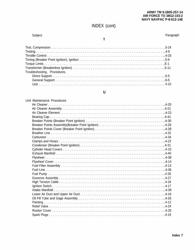
ARMY TM 9-2805-257-14AIR FORCE TO 38G2-103-2
NAVY NAVFAC P-8-612-14E
INDEX (cont)
Subject ParagraphT
Test, Compression . . . . . . . . . . . . . . . . . . . . . . . . . . . . . . . . . . . . . . . . . . . . . . . . . . . . . . . . . . . . . . ..5-24Testing . . . . . . . . . . . . . . . . . . . . . . . . . . . . . . . . . . . . . . . . . . . . . . . . . . . . . . . . . . . . . . . . . . . . . . ...4-6Throttle Control . . . . . . . . . . . . . . . . . . . . . . . . . . . . . . . . . . . . . . . . . . . . . . . . . . . . . . . . . . . . . . . . ...4-33Timing (Breaker Point Ignition), Ignition . . . . . . . . . . . . . . . . . . . . . . . . . . . . . . . . . . . . . . . . . . . . . ...5-9Torque Limits . . . . . . . . . . . . . . . . . . . . . . . . . . . . . . . . . . . . . . . . . . . . . . . . . . . . . . . . . . . . . . . . . . ..E-1Transformer (Breakerless Ignition) . . . . . . . . . . . . . . . . . . . . . . . . . . . . . . . . . . . . . . . . . . . . . . . . . ...5-11Troubleshooting, Procedures,
Direct Support . . . . . . . . . . . . . . . . . . . . . . . . . . . . . . . . . . . . . . . . . . . . . . . . . . . . . . . . . . . . . ...5-5General Support . . . . . . . . . . . . . . . . . . . . . . . . . . . . . . . . . . . . . . . . . . . . . . . . . . . . . . . . . . . ...6-5Unit . . . . . . . . . . . . . . . . . . . . . . . . . . . . . . . . . . . . . . . . . . . . . . . . . . . . . . . . . . . . . . . . . . . . . . . 4-10
U
Unit Maintenance ProceduresAir Cleaner . . . . . . . . . . . . . . . . . . . . . . . . . . . . . . . . . . . . . . . . . . . . . . . . . . . . . . . . . . . . . . . ...4-20Air Cleaner Assembly . . . . . . . . . . . . . . . . . . . . . . . . . . . . . . . . . . . . . . . . . . . . . . . . . . . . . . . ...4-21Air Cleaner Element . . . . . . . . . . . . . . . . . . . . . . . . . . . . . . . . . . . . . . . . . . . . . . . . . . . . . . . . ...4-23Bearing Cap . . . . . . . . . . . . . . . . . . . . . . . . . . . . . . . . . . . . . . . . . . . . . . . . . . . . . . . . . . . . . . ...4-41Breaker Points (Breaker Point Ignition) . . . . . . . . . . . . . . . . . . . . . . . . . . . . . . . . . . . . . . . . . . ...4-30Breaker Points Assembly(Breaker Point Ignition) . . . . . . . . . . . . . . . . . . . . . . . . . . . . . . . . . . ...4-29Breaker Points Cover (Breaker Point Ignition) . . . . . . . . . . . . . . . . . . . . . . . . . . . . . . . . . . . . ...4-28Breather Line . . . . . . . . . . . . . . . . . . . . . . . . . . . . . . . . . . . . . . . . . . . . . . . . . . . . . . . . . . . . . . ...4-32Carburetor . . . . . . . . . . . . . . . . . . . . . . . . . . . . . . . . . . . . . . . . . . . . . . . . . . . . . . . . . . . . . . . . ...4-34Clamps and Hoses . . . . . . . . . . . . . . . . . . . . . . . . . . . . . . . . . . . . . . . . . . . . . . . . . . . . . . . . . ...4-22Condenser (Breaker Point Ignition) . . . . . . . . . . . . . . . . . . . . . . . . . . . . . . . . . . . . . . . . . . . . . ...4-31Cylinder Head Covers . . . . . . . . . . . . . . . . . . . . . . . . . . . . . . . . . . . . . . . . . . . . . . . . . . . . . . . ...4-15Exhaust Manifold . . . . . . . . . . . . . . . . . . . . . . . . . . . . . . . . . . . . . . . . . . . . . . . . . . . . . . . . . . . ...4-40Flywheel . . . . . . . . . . . . . . . . . . . . . . . . . . . . . . . . . . . . . . . . . . . . . . . . . . . . . . . . . . . . . . . . . ...4-38Flywheel Cover . . . . . . . . . . . . . . . . . . . . . . . . . . . . . . . . . . . . . . . . . . . . . . . . . . . . . . . . . . . . ...4-14Fuel Filter Assembly . . . . . . . . . . . . . . . . . . . . . . . . . . . . . . . . . . . . . . . . . . . . . . . . . . . . . . . . ...4-13Fuel Line . . . . . . . . . . . . . . . . . . . . . . . . . . . . . . . . . . . . . . . . . . . . . . . . . . . . . . . . . . . . . . . . . ...4-36Fuel Pump . . . . . . . . . . . . . . . . . . . . . . . . . . . . . . . . . . . . . . . . . . . . . . . . . . . . . . . . . . . . . . . . ...4-35Governor Assembly . . . . . . . . . . . . . . . . . . . . . . . . . . . . . . . . . . . . . . . . . . . . . . . . . . . . . . . . . ...4-27High Tension Cable . . . . . . . . . . . . . . . . . . . . . . . . . . . . . . . . . . . . . . . . . . . . . . . . . . . . . . . . . ...4-18Ignition Switch . . . . . . . . . . . . . . . . . . . . . . . . . . . . . . . . . . . . . . . . . . . . . . . . . . . . . . . . . . . . . ...4-17Intake Manifold . . . . . . . . . . . . . . . . . . . . . . . . . . . . . . . . . . . . . . . . . . . . . . . . . . . . . . . . . . . . ...4-39Lower Air Duct and Upper Air Duct . . . . . . . . . . . . . . . . . . . . . . . . . . . . . . . . . . . . . . . . . . . . . ...4-16Oil Fill Tube and Gage Assembly. . . . . . . . . . . . . . . . . . . . . . . . . . . . . . . . . . . . . . . . . . . . . . ...4-26Painting . . . . . . . . . . . . . . . . . . . . . . . . . . . . . . . . . . . . . . . . . . . . . . . . . . . . . . . . . . . . . . . . . . ...4-12Relief Valve . . . . . . . . . . . . . . . . . . . . . . . . . . . . . . . . . . . . . . . . . . . . . . . . . . . . . . . . . . . . . . . ...4-24Rocker Cover . . . . . . . . . . . . . . . . . . . . . . . . . . . . . . . . . . . . . . . . . . . . . . . . . . . . . . . . . . . . ...4-25Spark Plugs . . . . . . . . . . . . . . . . . . . . . . . . . . . . . . . . . . . . . . . . . . . . . . . . . . . . . . . . . . . . . . . ...4-19
Index 7
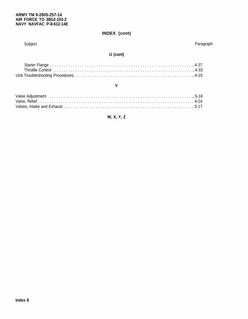
ARMY TM 9-2805-257-14AIR FORCE TO 38G2-103-2NAVY NAVFAC P-8-612-14E
Subject
INDEX (cont)
Paragraph
U (cont)
Starter Flange . . . . . . . . . . . . . . . . . . . . . . . . . . . . . . . . . . . . . . . . . . . . . . . . . . . . . . . . . . . . . ...4-37Throttle Control . . . . . . . . . . . . . . . . . . . . . . . . . . . . . . . . . . . . . . . . . . . . . . . . . . . . . . . . . . . . ...4-33
Unit Troubleshooting Procedures. . . . . . . . . . . . . . . . . . . . . . . . . . . . . . . . . . . . . . . . . . . . . . . . . . ...4-10
V
Valve Adjustment . . . . . . . . . . . . . . . . . . . . . . . . . . . . . . . . . . . . . . . . . . . . . . . . . . . . . . . . . . . . . . ...5-16Valve, Relief . . . . . . . . . . . . . . . . . . . . . . . . . . . . . . . . . . . . . . . . . . . . . . . . . . . . . . . . . . . . . . . . . . . . . 4-24Valves, Intake and Exhaust . . . . . . . . . . . . . . . . . . . . . . . . . . . . . . . . . . . . . . . . . . . . . . . . . . . . . . . ...5-17
W, X, Y, Z
Index 8
ARMY TM 9-2805-257-14AIR FORCE TO 38G2-103-2NAVY NAVFAC P-8-612-14E
By Order of the Secretaries of the Army, Air Force and Navy (Including the MarineC o r p s ) :
CARL E. VUONOG e n e r a l , U n i t e d S t a t e s
C h i e f o f S t a f f
O f f i c i a l :WILLIAM J. MEEHAN, I I
B r i g a d i e r G e n e r a l , United States ArmyThe Adjutant General
Army
LARRY D. WELCH, General USAFC h i e f o f S t a f f
O f f i c i a l :ALFRED G. HANSEN
General , USAF, Commander, Air ForceLogistics Comnand
B. F. M0NTOYARear Admiral, CEC, US NavyCommanderNavy Faci l i t ies Engineer ing Command
DISTRIBUTION:To be distributed in accordance with DA Form 12-25A, Operator, Unit, Direct Sup-
port and General Support Maintenance requirements for Engine, Gasoline, 3 HP,Models 2AO16-1/2/3.
*U .S . GOVERNMENT PRINT ING OFF ICE : 1990 754 -029 /20203

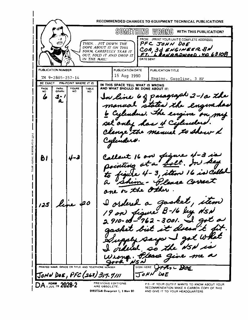

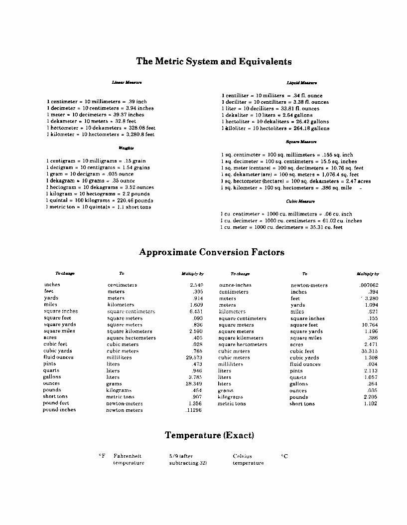

PIN: 067946-000

This fine document...
Was brought to you by me:
Liberated Manuals -- free army and government manuals
Why do I do it? I am tired of sleazy CD-ROM sellers, who take publicly available information, slap “watermarks” and other junk on it, and sell it. Those masters of search engine manipulation make sure that their sites that sell free information, come up first in search engines. They did not create it... They did not even scan it... Why should they get your money? Why are not letting you give those free manuals to your friends?
I am setting this document FREE. This document was made by the US Government and is NOT protected by Copyright. Feel free to share, republish, sell and so on.
I am not asking you for donations, fees or handouts. If you can, please provide a link to liberatedmanuals.com, so that free manuals come up first in search engines:
<A HREF=http://www.liberatedmanuals.com/>Free Military and Government Manuals</A>
– SincerelyIgor Chudovhttp://igor.chudov.com/
– Chicago Machinery Movers


![SITREP, OVER! · 2021. 4. 19. · SS-Panzer-Aufklärunsabteilung) located in Grüssow [on the island of Usedom]. The battalion commander was Sturmbannführer Rudolf ... he joined](https://img.pdfslide.net/doc/110x75/614ab27b12c9616cbc699546/sitrep-over-2021-4-19-ss-panzer-aufklrunsabteilung-located-in-grssow.jpg)