Embed Size (px)
Citation preview

Technical Manual - English
System Board D3049for PRIMERGY TX140 S1 / TX120 S3 Technical Manual
Edition May 2012

Comments… Suggestions… Corrections…The User Documentation Department would like toknow your opinion of this manual. Your feedback helpsus optimize our documentation to suit your individual needs.
Feel free to send us your comments by e-mail to [email protected].
Certified documentation according to DIN EN ISO 9001:2008To ensure a consistently high quality standard anduser-friendliness, this documentation was created tomeet the regulations of a quality management system which complies with the requirements of the standardDIN EN ISO 9001:2008.
cognitas. Gesellschaft für Technik-Dokumentation mbHwww.cognitas.de
Copyright and TrademarksCopyright © 2012 Fujitsu Technology Solutions GmbH.
All rights reserved.Delivery subject to availability; right of technical modifications reserved.
All hardware and software names used are trademarks of their respective manufacturers.
– The contents of this manual may be revised without prior notice.
– Fujitsu assumes no liability for damages to third party copyrights or other rights arising from the use of any information in this manual.
– No part of this manual may be reproduced in any form without the prior written permission of Fujitsu.
Microsoft, Windows, Windows Server, and Hyper V are trademarks or registered trademarks of Microsoft Corporation in the USA and other countries.
Intel and Xeon are trademarks or registered trademarks of Intel Corporation or its subsidiaries in the USA and other countries.

TX140 S1 / TX120 S3 Technical Manual
Before reading this manual
For your safety
This manual contains important information for safely and correctly using this product.
Carefully read the manual before using this product. Pay particular attention to the accompanying manual "Safety Notes and Regulations" and ensure these safety notes are understood before using the product. Keep this manual and the manual "Safety Notes and Regulations" in a safe place for easy reference while using this product.
Radio interference
This product is a "Class A" ITE (Information Technology Equipment). In a domestic environment this product may cause radio interference, in which case the user may be required to take appropriate measures. VCCI-A
Aluminum electrolytic capacitors
The aluminum electrolytic capacitors used in the product's printed circuit board assemblies and in the mouse and keyboard are limited-life components. Use of these components beyond their operating life may result in electrolyte leakage or depletion, potentially causing emission of foul odor or smoke.
As a guideline, in a normal office environment (25°C) operating life is not expected to be reached within the maintenance support period (5 years). However, operating life may be reached more quickly if, for example, the product is used in a hot environment. The customer shall bear the cost of replacing replaceable components which have exceeded their operating life. Note that these are only guidelines, and do not constitute a guarantee of trouble-free operation during the maintenance support period.
High safety use
This product has been designed and manufactured for general uses such as general office use, personal use, domestic use and normal industrial use. It has not been designed or manufactured for uses which demand an extremely high level of safety and carry a direct and serious risk to life or body if such safety cannot be ensured.
Technical Manual TX140 S1 / TX120 S3
These uses include control of nuclear reactions in nuclear power plants, automatic airplane flight control, air traffic control, traffic control in mass transport systems, medical devices for life support, and missile guidance control in weapons systems (hereafter, "high safety use"). Customers should not use this product for high safety use unless measures are in place for ensuring the level of safety demanded of such use. Please consult the sales staff of Fujitsu if intending to use this product for high safety use.
Measures against momentary voltage drop
This product may be affected by a momentary voltage drop in the power supply caused by lightning. To prevent a momentary voltage drop, use of an AC uninterruptible power supply is recommended.
(This notice follows the guidelines of Voltage Dip Immunity of Personal Computer issued by JEITA, the Japan Electronics and Information Technology Industries Association.)
Technology controlled by the Foreign Exchange and Foreign Trade Control Law of Japan
Documents produced by Fujitsu may contain technology controlled by the Foreign Exchange and Foreign Trade Control Law of Japan. Documents which contain such technology should not be exported from Japan or transferred to non-residents of Japan without first obtaining authorization in accordance with the above law.
Harmonic Current Standards
This product conforms to harmonic current standard JIS C 61000-3-2.
Only for the Japanese market: About SATA hard disk drives
The SATA version of this server supports hard disk drives with SATA / BC-SATA storage interfaces. Please note that the usage and operation conditions differ depending on the type of hard disk drive used.
Please refer to the following internet address for further information on the usage and operation conditions of each available type of hard disk drive:
http://jp.fujitsu.com/platform/server/primergy/harddisk/

TX140 S1 / TX120 S3 Technical Manual
Only for the Japanese market:
I Although described in this manual, some sections do not apply to the Japanese market. These options and routines include:
– USB Flash Module (UFM)
– CSS (Customer Self Service)

Technical Manual TX140 S1 / TX120 S3

TX140 S1 / TX120 S3 Technical Manual
Contents
1 Introduction . . . . . . . . . . . . . . . . . . . . . . . . . . . . 9
1.1 Notational conventions . . . . . . . . . . . . . . . . . . . . 10
2 Important information . . . . . . . . . . . . . . . . . . . . . 11
2.1 Notes on safety . . . . . . . . . . . . . . . . . . . . . . . . . 11
2.2 CE certificate of conformity . . . . . . . . . . . . . . . . . . 14
2.3 Environmental protection . . . . . . . . . . . . . . . . . . . 15
3 Features . . . . . . . . . . . . . . . . . . . . . . . . . . . . . 17
3.1 Overview . . . . . . . . . . . . . . . . . . . . . . . . . . . . 20
3.2 Main memory . . . . . . . . . . . . . . . . . . . . . . . . . . 243.2.1 Module population . . . . . . . . . . . . . . . . . . . . . . . . 243.2.1.1 Types of memory modules . . . . . . . . . . . . . . . . . . 243.2.1.2 Modes of operation . . . . . . . . . . . . . . . . . . . . . . 25
3.3 PCI slots . . . . . . . . . . . . . . . . . . . . . . . . . . . . . 26
3.4 Screen resolution . . . . . . . . . . . . . . . . . . . . . . . 27
3.5 Temperature / system monitoring . . . . . . . . . . . . . . . 27
3.6 Connectors and indicators . . . . . . . . . . . . . . . . . . 293.6.1 System board . . . . . . . . . . . . . . . . . . . . . . . . . . 293.6.2 Connector panel . . . . . . . . . . . . . . . . . . . . . . . . . 33
3.7 Settings . . . . . . . . . . . . . . . . . . . . . . . . . . . . . 353.7.1 Jumper . . . . . . . . . . . . . . . . . . . . . . . . . . . . . . 35
8 Technical Manual TX140 S1 / TX120 S3
Contents

TX140 S1 / TX120 S3 Technical Manual 9
1 IntroductionThis technical manual describes the system board D3049, which can be equipped with one processor.
For additional driver information (if available), refer to the Readme files located on the server hard disk and on the supplied DVDs (see Installation DVD of ServerView Suite - ServerView Software Products).
You will find further information about the BIOS setup in the "D3049 BIOS Setup Utility for PRIMERGY TX140 S1 / TX120 S3" manual.
I PRIMERGY manuals are available in PDF format on the ServerView Suite DVD 2. The ServerView Suite DVD 2 is part of the ServerView Suite supplied with every server.
PRIMERGY Abbreviations and Glossary can also be found on the ServerView Suite DVD 2.
Model lines for TX140 S1
There are two model lines for the TX140 S1 server:
– TX140 S1– TX140 S1p
I For the European market:
You can identify the model line by the model name "TX140 S1p" printed on the identification rating plate and on the ID card.
I For the Japanese market:
"TX140 S1p" is not used as the model name in the Japanese market.
You can identify the model line by the product number; The product number "PYT14Pxxx" means TX140 S1p.
For an overview of the different features please refer to table 1 on page 17.

10 Technical Manual TX140 S1 / TX120 S3
Introduction
Model lines for TX120 S3
There are two model lines for the TX120 S3 server:
– TX120 S3– TX120 S3p
I For the European market:
You can identify the model line by the model name "TX120 S3p" printed on the identification rating plate and on the ID card.
I For the Japanese market:
"TX120 S3p" is not used as the model name in the Japanese market.
You can identify the model line by the product number; The product number "PYT12Pxxx" means TX120 S3p.
For an overview of the different features please refer to table 2 on page 18.
1.1 Notational conventions
The following notational conventions are used in this manual:
Text in italics indicates commands or menu items."Quotation marks" indicate names of chapters and terms that are being
emphasized.Ê describes activities that must be performed in the order
shown.V CAUTION! pay particular attention to texts marked with this symbol.
Failure to observe this warning may endanger your life, destroy the system or lead to the loss of data.
I indicates additional information, notes and tips.

TX140 S1 / TX120 S3 Technical Manual 11
2 Important informationIn this chapter you will find essential information regarding safety when working with your server.
V CAUTION!
With the system board installed you must open the system to access the system board. How to access the system board of your system is described in the appropriate Upgrade and Maintenance Manual.
When handling the system board, refer to the specific notes on safety in the Operating Manual and/or Upgrade and Maintenance Manual for the respective server.
2.1 Notes on safety
V CAUTION!
● The actions described in these instructions should only be performed by authorized, qualified personnel. Equipment repairs should only be performed by qualified staff. Any failure to observe the guidelines in this manual, and any unauthorized openings and improper repairs could expose the user to risks (electric shock, fire hazards) and could also damage the equipment. Please note that any unauthorized openings of the device will result in the invalidation of the warranty and exclusion from all liability.
● Transport the device only in the antistatic original packaging or in packaging that protects it from knocks and jolts.
● Only install expansions that are allowed for the system board. If you install other expansions, you may damage the requirements and rules governing safety and electromagnetic compatibility or your system. Information on which system expansions are approved for installation can be obtained from our customer service center or your sales outlet.
● The warranty expires if the device is damaged during the installation or replacement of system expansions.

12 Technical Manual TX140 S1 / TX120 S3
Important information
V CAUTION!
● Components can become very hot during operation. Ensure you do not touch components when making extensions to the system board. There is a danger of burns!
● Transmission lines to peripheral devices must be adequately shielded.
● Ethernet cabling has to comply with EN 50173 and EN 50174-1/2 standards or ISO/IEC 11801 standard respectively. The minimum requirement is a Category 5 shielded cable for 10/100 Ethernet, or Category 5e for Gigabit Ethernet.
● Never connect or disconnect data transmission lines during a storm (risk of lightning hazard).
Batteries
V CAUTION!
● Incorrect replacement of batteries may result in a risk of explosion. The batteries may only be replaced with identical batteries or with a type recommended by the manufacturer (this information doesn’t apply to the Japanese market).
It is essential to observe the instructions in the Upgrade and Maintenance Manual for the respective server.

TX140 S1 / TX120 S3 Technical Manual 13
Important information
Modules with Electrostatic-Sensitive Devices
Modules with electrostatic-sensitive devices are identified by the following sticker:
Figure 1: ESD label
When you handle components fitted with ESDs, you must always observe the following points:
● Switch off the system and remove the power plugs from the power outlets before installing or removing components with ESDs.
● You must always discharge static build-up (e.g. by touching a grounded object) before working with such components.
● Any devices or tools that are used must be free of electrostatic charge.
● Wear a suitable grounding cable that connects you to the external chassis of the system unit.
● Always hold components with ESDs at the edges or at the points marked green (touch points).
● Do not touch any connectors or conduction paths on an ESD.
● Place all the components on a pad which is free of electrostatic charge.
I For a detailed description of how to handle ESD components, see the relevant European or international standards (EN 61340-5-1, ANSI/ESD S20.20).

14 Technical Manual TX140 S1 / TX120 S3
Important information
Notes about boards
● During installation/deinstallation of the board, observe the specific instructions described in the Upgrade and Maintenance Manual for the respective server.
● Shut down the server and disconnect the power plug, before you make modifications on an installed board.
● To prevent damage to the board, the components and conductors on it, please take great care when you insert or remove boards. Take great care to ensure that extension boards are slotted in straight, without damaging components or conductors on the board, or any other components, for example EMI spring contacts.
● Be careful with the locking mechanisms (catches, centring pins etc.) when you replace the system board or components on it, for example memory modules or processors.
● Never use sharp objects (screw drivers) for leverage.
● Do not damage or modify internal cables or devices. Doing so may cause a device failure, fire, or electric shock.
● Do not touch the circuitry on boards or soldered parts. Hold the metallic areas or the edges of the circuit boards.
2.2 CE certificate of conformity
The board complies with the requirements of the EC directives 2004/108/EC regarding “Electromagnetic Compatibility” and 2006/95/EC “Low Voltage Directive”. This is indicated by the CE marking (CE = Communauté Européenne).
Compliance was tested in a typical PRIMERGY configuration.

TX140 S1 / TX120 S3 Technical Manual 15
Important information
2.3 Environmental protection
Environmentally-friendly product design and development
This product has been designed in accordance with the Fujitsu standard for "environmentally friendly product design and development". This means that key factors such as durability, selection and labeling of materials, emissions, packaging, ease of dismantling and recycling have been taken into account.
This saves resources and thus reduces the harm done to the environment. Further information can be found at:
– http://ts.fujitsu.com/products/standard_servers/index.html (for the EMEA market)– http://jp.fujitsu.com/platform/server/primergy/concept/ (for the Japanese
market)
Energy-saving information
Devices that do not need to be constantly switched on should be switched off until they are needed as well as during long breaks and after completion of work.
Packaging information
This packaging information doesn’t apply to the Japanese market.
Do not throw away the packaging. You may need it later for transporting the system. If possible, the equipment should only be transported in its original packaging.
Information on handling consumables
Please dispose of printer consumables and batteries in accordance with the applicable national regulations.
In accordance with EU directives, batteries must not be disposed of with unsorted domestic waste. They can be returned free of charge to the manufacturer, dealer or an authorized agent for recycling or disposal.
All batteries containing pollutants are marked with a symbol (a crossed-out garbage can). They are also marked with the chemical symbol for the heavy metal that causes them to be categorized as containing pollutants:
Cd CadmiumHg MercuryPb Lead

16 Technical Manual TX140 S1 / TX120 S3
Important information
Labels on plastic casing parts
Please avoid sticking your own labels on plastic parts wherever possible, since this makes it difficult to recycle them.
Returns, recycling and disposal
Please handle returns, recycling and disposal in accordance with local regulations.
Details regarding the return and recycling of devices and consumables within Europe can also be found in the "Returning used devices" manual, via your local Fujitsu branch or from our recycling center in Paderborn:
Fujitsu Technology SolutionsRecycling CenterD-33106 Paderborn
Tel. +49 5251 525 1410Fax +49 5251 525 32 1410
The device must not be disposed of with domestic waste. This device is labeled in compliance with European directive 2002/96/EC on waste electrical and electronic equipment (WEEE).
This directive sets the framework for returning and recycling used equipment and is valid across the EU. When returning your used device, please use the return and collection systems available to you. Further information can be found at http://ts.fujitsu.com/recycling.

TX140 S1 / TX120 S3 Technical Manual 17
3 FeaturesModel lines for TX140 S1
There are two model lines for the TX140 S1 server:
– TX140 S1– TX140 S1p
The following table provides an overview of the different features:
TX140 S1 TX140 S1pSystem board D3049-Axx D3049-BxxProcessors Intel® XEON® E3-1200
processor series
Intel® Pentium® processor series
Intel® Core™ i3-2100 processor series
Intel® XEON® E3-1200v2 processor series
Intel® Pentium® processor series
Intel® Core™ i3 processor series
Main Memory DDR3 UDIMM with 1333 MHz speed
up to 21 GB/s bandwidth in dual channel mode and 10.6 GB/s in single channel mode
DDR3 UDIMM with 1600 MHz speed
up to 25.6 GB/s bandwidth in dual channel mode and 12.8 GB/s in single channel mode
PCI slots 1x PCI 3.0 (32 Bit / 33MHz)
1x PCIe x16 Gen 2
1x PCIe x4 Gen 2 (mechanical x8)
1x PCIe x1 Gen 2 (mechanical x4 notched)
1x PCI 3.0 (32 Bit / 33MHz)
1x PCIe x16 Gen 3
1x PCIe x4 Gen 2 (mechanical x8)
1x PCIe x1 Gen 2 (mechanical x4 notched)
Table 1: Differences between TX140 S1 and TX140 S1p

18 Technical Manual TX140 S1 / TX120 S3
Features
I For the EMEA market:
You can identify the model line by the model name "TX140 S1p" printed on the identification rating plate and on the ID card.
I For the Japanese market:
"TX140 S1p" is not used as the model name in the Japanese market.
You can identify the model line by the product number; The product number "PYT14Pxxx" means TX140 S1p.
Model lines for TX120 S3
There are two model lines for the TX120 S3 server:
– TX120 S3– TX120 S3p
The following table provides an overview of the different features:
TX120 S3 TX120 S3pSystem board D3049-Axx D3049-BxxProcessors Intel® XEON® E3-1200
processor series
Intel® Pentium® / Celeron® processor series
Intel® Core™ i3-2100 processor series
Intel® XEON® E3-1200v2 processor series
Intel® Pentium® / Celeron® processor series
Intel® Core™ i3processor series
Main Memory DDR3 UDIMM with 1333 MHz speed
up to 21 GB/s bandwidth in dual channel mode and 10.6 GB/s in single channel mode
DDR3 UDIMM with 1600 MHz speed
up to 25.6 GB/s bandwidth in dual channel mode and 12.8 GB/s in single channel mode
Table 2: Differences between TX120 S3 and TX120 S3p

TX140 S1 / TX120 S3 Technical Manual 19
Features
I For the EMEA market:
You can identify the model line by the model name "TX120 S3p" printed on the identification rating plate and on the ID card.
I For the Japanese market:
"TX120 S3p" is not used as the model name in the Japanese market.
You can identify the model line by the product number; The product number "PYT12Pxxx" means TX120 S3p.
PCI slots 1x PCI 3.0 (32 Bit / 33MHz)
1x PCIe x16 Gen 2
1x PCIe x4 Gen 2 (mechanical x8)
1x PCIe x1 Gen 2 (mechanical x4 notched)
1x PCI 3.0 (32 Bit / 33MHz)
1x PCIe x16 Gen 3
1x PCIe x4 Gen 2 (mechanical x8)
1x PCIe x1 Gen 2 (mechanical x4 notched)
TX120 S3 TX120 S3p
Table 2: Differences between TX120 S3 and TX120 S3p

20 Technical Manual TX140 S1 / TX120 S3
Features
3.1 Overview
Processors
– one processor socket LGA1155– one Intel® Xeon® Pentium®, or Core i3 processor– CPUs with up to 95 W TDP (FMB 2011D) are supported
Main memory
– up to 4 slots for main memory– up to 4 DDR3 UDIMM (unbuffered DIMM) memory modules– only DIMMs with ECC are supported– minimum memory configuration: one DIMM in DIMM1A– maximum memory configuration: four DIMM in all slots– up to 25.6 GB/s bandwidth in dual channel mode and 12.8 GB/s in single
channel mode– ECC multiple bit error detection and single bit error correction
Chips on the system board
– Intel® C202 chipset– Gigabit Ethernet controller (Intel® 82574L)– Gigabit Ethernet PHY controller (Intel® 82579LM)– Realtek® RTL8211E Gigabit Ethernet PHY– onboard iRMC S3 Server Management Controller with integrated graphics
controller– 32 MB SPI Flash (code) and 2 MB SPI Flash (data) for iRMC S3– 128 MB DDR3-800 SRAM for iRMC S3– 8 MB SPI Flash BIOS / ME firmware

TX140 S1 / TX120 S3 Technical Manual 21
Features
Internal connectors
– 1x USB CCR / DAT connector(only one of both can be used at the same time)
– 1x Mini SAS/SATA connector (4 ports)– 2x SATA connectors– 1x power supply connector 16 pin (12V and 12V auxiliary)– 1x SATA power connector 8 pin (12V, 5V) for HDD and optical drives– 1x PC2009 connector– 1x front panel server connector (26 pin)– 1x connector for front LAN module (optional)– 1x connector for USB Flash Module (optional)– 1x connector for TPM (optional)– 2x connectors for system fans (4 pin)– 1x connector for CPU fan (4 pin)– 1x intrusion connector– 1x connector for HDD activity LED– 1x RST connector for 3rd party reset button
External connectors
– front side:
– 2x USB 2.0 connectors– 1x RJ45 LAN connector (optional)
– rear side:
– 1x serial connector (COM1) – 1x video connector (VGA)– 6x USB 2.0 connectors– 3x RJ45 LAN connectors
PCI slots
– 3 x PCI-Express slots:
– 1x PCIe x1 slot– 1x PCIe x4 slot– 1x PCIe x16 slot
– 1 x PCI slot (32 bit / 33 MHz)

22 Technical Manual TX140 S1 / TX120 S3
Features
Power management
– ACPI (states S0, S4, S5)– 3.3 V auxiliary power on the PCI / PCI Express slots– on/off/sleep/wake by power button– on/off by software– wake on by RTC, external serial connector (COM1), LAN, PCI, PCI Express
controller and iRMC S3– power on by power button, external serial connector, LAN, PCI, PCI Express
controller and iRMC S3– 0-Watt standby support with management interval
BIOS features
– AMI Aptio– SMBIOS 2.6 (DMI)– Server Hardware Design Guide– WfM 2.0– ACPI 4.0 support– LSI SAS/RAID BIOS– USB keyboard/mouse– boot possible from:
– CD-ROM/DVD (IDE, SATA, SAS)– hard disk (SATA, SAS, SCSI, USB)– LAN
– console redirection support– OEM logo– CPU, memory disable
Environmental protection
– battery in holder
Form factor
– µATX 244 x 244 mm
CSS (Customer Self Service)
This system board supports the CSS functionality. You will find a description of CSS functionality in the Operating Manual of your server.

TX140 S1 / TX120 S3 Technical Manual 23
Features
USB Flash Module (option)
The system board can be equipped with an USB Flash Module (UFM) by the manufacturer or by an add-on kit. The module is used by VMware.
TPM (option)
The system board can be equipped with a TPM (Trusted Platform Module) by the manufacturer or by an add-on kit. This module enables programs from third party manufacturers to store key information (e.g. drive encryption using Windows Bitlocker Drive Encryption).
The TPM is activated via the BIOS system (for more information, refer to the BIOS manual).
V CAUTION!
– When using the TPM, note the program descriptions provided by the third party manufacturers.
– You must also create a backup of the TPM content. To do this, follow the third party manufacturer's instructions. Without this backup, if the TPM or the system board is faulty you will not be able to access your data.
– If a failure occurs, please inform your service about the TPM activation before it takes any action, and be prepared to provide them with your backup copies of the TPM content.

24 Technical Manual TX140 S1 / TX120 S3
Features
3.2 Main memory
I You will find the descriptions how to install memory modules in the Upgrade and Maintenance Manual of your server.
Figure 2: Slots of the main memory
3.2.1 Module population
– Memory slot 1 / channel A (DIMM 1A) needs to be populated first.
– Within all channels memory slot 1 must be populated prior to slot 2.
– Install memory modules within a channel in descending order of capacity: higher capacity in slot 1, lower capacity in slot 2.
3.2.1.1 Types of memory modules
UDIMM memory modules
Technology: DDR3 1333/1600 unbuffered single rank (SR) or dual rank (DR) UDIMM memory modules with ECC. Support for up to 4 UDIMM memory modules.
Total memory size: up to 32 GB
POW
ER1
DIMM2ADIMM1A
DIMM2BDIMM1B
CPU
Fron
t pan
el U
SB
SATA POWER
PC20
09
Jumper
COM1
VGA
ManagementLAN/USB 9/10
FAN2 SYS
FRONT LAN

TX140 S1 / TX120 S3 Technical Manual 25
Features
3.2.1.2 Modes of operation
Figure 3: Dual-channel symmetric and asymmetric mode
– The maximum performance can be achieved in a symmetric dual-channel configuration. Therefore both channels have to be populated with the same amount of memory. The DRAM device technology (1 Gbit / 2 Gbit / 4 Gbit) may vary from one channel to the other.
– If the amount of memory differs between the two channels, the system board will run in dual-channel asymmetric mode.
– Regardless of the mode, all DIMMs will run at the highest common frequency that is allowed by the SPD Data of the DIMMs and the maximum speed of the selected configuration.
– Single-channel mode is used when 1 memory module is populated in DIMM 1A.
Configuration per channel
Max. speed DIMM-2 DIMM-1
1 DDR3-1333/1600 empty SR/DR2 DDR3-1333/1600 SR/DR SR/DR
channe lA B
Dua
l mo
de
M em ory s ize
channe lA B
Dua
l mo
deS
ing
lem
ode
Dual-channel symmetric mode Dual-channel asymmetric mode
M em ory s ize A
M em ory s ize B

26 Technical Manual TX140 S1 / TX120 S3
Features
3.3 PCI slots
Figure 4: PCI slots
PCI slot Type Function1 PCI 32 32-bit / 33 MHz PCI slot2 PCIe x1 PCIe x1 slot3 PCIe x4 PCIe x4 slot 4 PCIe x16 PCIe x16 slot
Slot 3 PCIe x4
Slot 1 PCI 32 Bit / 33 MHz
FAN1 SYS
Intrusion
SATA MLC1
USB1 DAT
HDD ACTIVITY
Battery
Indicate CSS
SATA6
SATA
5
TPM
Slot 2 PCIe x1
Standard LAN/USB 5/6
Slot 4 PCIe x16
iRMC 3 Cougar Point PCH
USB1AUX
UFM

TX140 S1 / TX120 S3 Technical Manual 27
Features
3.4 Screen resolution
Depending on the operating system used the screen resolutions in the following table refer to the graphic controller on the system board. The graphic controller is integrated in the iRMC S3 (integrated Remote Management Controller).
If you are using an external graphic controller, you will find details of supported screen resolutions in the Operating Manual or Technical Manual supplied with the graphic controller.
3.5 Temperature / system monitoring
Temperature and system monitoring aim to reliably protect the computer hardware against damage caused by overheating. In addition, any unnecessary noise is also prevented by reducing the fan speed, and information is provided about the system status.
The following functions are supported:
Temperature monitoring
Measurement of the processor and the system internal temperature by an onboard temperature sensor, measurement of the ambient temperature by a I2C temperature sensor.
Fan monitoring
The power supply unit and system fans are monitored. Fans that are no longer available, blocked or stuck fans are detected.
Screen resolution (pixel)
Maximum refresh rate (Hz)
Max. number of colours
640x480 85 32 bit800x600 85 32 bit1024x768 75 32 bit1152x864 60 16 bit1280x1024 60 24 bit1600x1200 60 16 bit
28 Technical Manual TX140 S1 / TX120 S3
Features
Fan control
The fans are regulated according to temperature.
Sensor monitoring
The removal of, or a fault in, a temperature sensor is detected. Should this happen all fans monitored by this sensor run at maximum speed, to achieve the greatest possible protection of the hardware.
Voltage monitoring
When voltage exceeds warning level high or falls below warning level low an alert will be generated.
Cover monitoring (optional)
Unauthorized opening of the cover is detected, even when the system is switched off. However, this will only be indicated when the system is switched on again.
System Event Log (SEL)
All monitored events of the system board are signalized via the Global Error LED or CSS LED and recorded in the System Event Log. They could be retrieved in the BIOS Setup, iRMC S3’s Web interface or via the ServerView Operations Manager.
PRIMERGY Local Diagnostic LEDs
Optical signaling through the LEDs on the system board identifies defective modules and components (CSS functionality) as well as gaining information on the PDA (Prefailure Detection and Analysis).
TX140 S1 / TX120 S3 Technical Manual 29
Features
3.6 Connectors and indicators
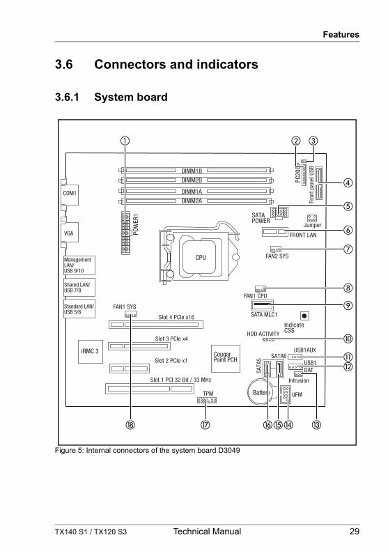
3.6.1 System board
Figure 5: Internal connectors of the system board D3049
Slot 3 PCIe x4
Slot 1 PCI 32 Bit / 33 MHz
POW
ER1
FAN1 SYS
Intrusion
SATA MLC1
USB1 DAT
HDD ACTIVITY
Battery
DIMM2ADIMM1A
DIMM2BDIMM1B
Indicate CSS
CPU
SATA6
SATA
5
Fron
t pan
el U
SB
SATA POWER
PC20
09
TPM
Slot 2 PCIe x1
Jumper
COM1
VGA
ManagementLAN/USB 9/10
Shared LAN/USB 7/8
Standard LAN/USB 5/6
Slot 4 PCIe x16
iRMC 3 Cougar Point PCH
USB1AUX
FAN1 CPU
FAN2 SYS
FRONT LAN
UFM
30 Technical Manual TX140 S1 / TX120 S3
Features
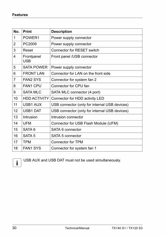
I USB AUX and USB DAT must not be used simultaneously.
No. Print Description1 POWER1 Power supply connector2 PC2009 Power supply connector3 Reset Connector for RESET switch4 Frontpanel
USBFront panel /USB connector
5 SATA POWER Power supply connector6 FRONT LAN Connector for LAN on the front side7 FAN2 SYS Connector for system fan 28 FAN1 CPU Connector for CPU fan9 SATA MLC SATA MLC connector (4 port)10 HDD ACTIVITY Connector for HDD activity LED11 USB1 AUX USB connector (only for internal USB devices)12 USB1 DAT USB connector (only for internal USB devices)13 Intrusion Intrusion connector14 UFM Connector for USB Flash Module (UFM)15 SATA 6 SATA 6 connector16 SATA 5 SATA 5 connector17 TPM Connector for TPM18 FAN1 SYS Connector for system fan 1
TX140 S1 / TX120 S3 Technical Manual 31
Features
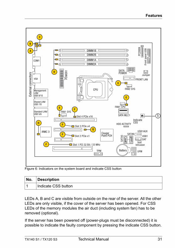
Figure 6: Indicators on the system board and indicate CSS button
LEDs A, B and C are visible from outside on the rear of the server. All the other LEDs are only visible, if the cover of the server has been opened. For CSS LEDs of the memory modules the air duct (including system fan) has to be removed (optional).
If the server has been powered off (power-plugs must be disconnected) it is possible to indicate the faulty component by pressing the indicate CSS button.
No. Description1 Indicate CSS button
Slot 3 PCIe x4
Slot 1 PCI 32 Bit / 33 MHz
POW
ER1
FAN1 SYS
Intrusion
SATA MLC1
USB1 DAT
HDD ACTIVITY
Battery
DIMM2ADIMM1A
DIMM2BDIMM1B
Indicate CSS
CPU
SATA6
SATA
5
Fron
t pan
el U
SB
SATA POWER
PC20
09
TPM
Slot 2 PCIe x1
Jumper
H
COM1
VGA
Exte
rnal
con
nect
ors
ManagementLAN/USB 9/10
Shared LAN/USB 7/8
Standard LAN/USB 5/6
Slot 4 PCIe x16
iRMC 3 Cougar Point PCH
USB1AUX
FAN1 CPU
FAN2 SYS
FRONT LAN
UFM
G

32 Technical Manual TX140 S1 / TX120 S3
Features
The LEDs have the following meaning:
LED Indicator MeaningA - GEL(Global Error LED)
off no error (non CSS component)orange on indicates a prefailure (non CSS
component)orange flashing indicates a failure of a non CSS
component.Reasons for a failure may be:
– over temperature measured by one of the sensors
– sensor is defective– CPU error– software detected an error
B - CSS(Customer Self Service)
off no error (CSS component)yellow on indicates a prefailure (CSS component)yellow flashing indicates a failure (CSS component)
C - Identification blue on server is identified via the ServerView Operations Manager or by ID button
blue flashing local monitor offD - Memory off memory module running
orange on memory module failureE - System fan CPU fan (optional)
off fan runningorange on fan failure
F - PCI card off PCI card okayorange on PCI card failure
G - AUX power yellow on all aux voltages okayH - iRMC green flashing iRMC S3 is okay
TX140 S1 / TX120 S3 Technical Manual 33
Features
3.6.2 Connector panel
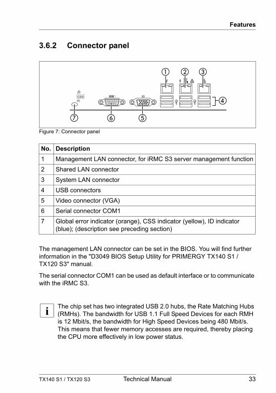
Figure 7: Connector panel
The management LAN connector can be set in the BIOS. You will find further information in the "D3049 BIOS Setup Utility for PRIMERGY TX140 S1 / TX120 S3" manual.
The serial connector COM1 can be used as default interface or to communicate with the iRMC S3.
I The chip set has two integrated USB 2.0 hubs, the Rate Matching Hubs (RMHs). The bandwidth for USB 1.1 Full Speed Devices for each RMH is 12 Mbit/s, the bandwidth for High Speed Devices being 480 Mbit/s. This means that fewer memory accesses are required, thereby placing the CPU more effectively in low power status.
No. Description1 Management LAN connector, for iRMC S3 server management function2 Shared LAN connector 3 System LAN connector 4 USB connectors5 Video connector (VGA)6 Serial connector COM17 Global error indicator (orange), CSS indicator (yellow), ID indicator
(blue); (description see preceding section)

34 Technical Manual TX140 S1 / TX120 S3
Features
LAN connectors
The system board is equipped with a Gigabit Ethernet Controller of the type Intel® 82574L and 82579LM. The LAN controller supports transmission rates of 10 Mbit/s, 100 Mbit/s and 1 Gbit/s.
The LAN controller (only for Shared LAN) also supports WOL functionality by means of Magic Packet™. It is also possible to start a system via a LAN without a separate boot hard disk drive. PXE is supported here.
The separate management LAN connector is used as a management interface (iRMC S3) and is prepared for operation with the Remote Management. Optionally LAN connector 2 (center) can also be used for iRMC S3 server management.
Each LAN connector has two LEDs which display the speed of the connection and its status:
Figure 8: LAN LEDs
No. Indicator Description1 LAN
link/transferSteady green signal when a LAN connection exists.
Remains dark when no LAN connection exists.
Flashes green when LAN transfer takes place.2 LAN speed Steady yellow signal (without Management LAN) in the
event of a LAN transfer rate of 1 Gbit/s
Steady green signal in the event of a LAN transfer rate of 100 Mbit/s.
Remains dark in the event of a LAN transfer rate of 10 Mbit/s.
TX140 S1 / TX120 S3 Technical Manual 35
Features
3.7 Settings
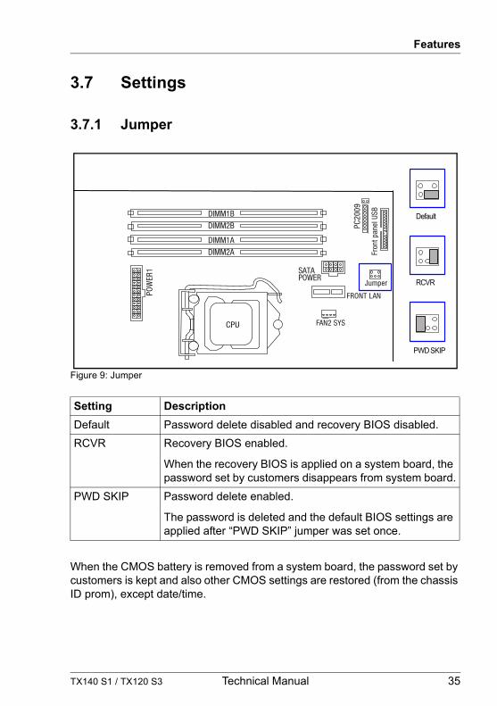
3.7.1 Jumper
Figure 9: Jumper
When the CMOS battery is removed from a system board, the password set by customers is kept and also other CMOS settings are restored (from the chassis ID prom), except date/time.
Setting DescriptionDefault Password delete disabled and recovery BIOS disabled.RCVR Recovery BIOS enabled.
When the recovery BIOS is applied on a system board, the password set by customers disappears from system board.
PWD SKIP Password delete enabled.
The password is deleted and the default BIOS settings are applied after “PWD SKIP” jumper was set once.
Default
RCVR
PWD SKIP
POW
ER1
DIMM2ADIMM1A
DIMM2BDIMM1B
CPU
Fron
t pan
el U
SB
SATA POWER
PC20
09
Jumper
FAN2 SYS
FRONT LAN

36 Technical Manual TX140 S1 / TX120 S3
Features

![Civic Reception House Nagoya EntranceTechnical Tour2 Technical Tour3 Technical Tour4 Technical Tour5 [12] Technical Tour6 Technical Tour7 Technical Tour8 Technical Tour9 Technical](https://img.pdfslide.net/doc/110x75/60511276b5492f765a3fd03c/civic-reception-house-nagoya-entrance-technical-tour2-technical-tour3-technical.jpg)