Embed Size (px)
Citation preview

MDT technologies GmbH • 51766 Engelskirchen • Papiermühle 1
Tel.: +49-2263-880 • Fax: +49-2263-4588 • [email protected] • www.mdt.de
Stand 2/2016
Technical Manual
MDT
Time Switch
SCN-RTC20.01

Technical Manual Time Switch SCN-RTC20.01
MDT technologies GmbH • 51766 Engelskirchen • Papiermühle 1
Tel.: +49-2263-880 • Fax: +49-2263-4588 • [email protected] • www.mdt.de 2
1 Content
1 Content ................................................................................................................................................. 2
2 Overview ............................................................................................................................................... 4
2.1 Overview Devices .......................................................................................................................... 4
2.2 Usage & Areas of application ........................................................................................................ 4
2.3 Exemplary Circuit diagram ............................................................................................................ 5
2.4 Design & Usage .............................................................................................................................. 5
2.5 Functions ....................................................................................................................................... 6
2.7. Starting up .................................................................................................................................... 6
3 Communication objects ........................................................................................................................ 7
3.1 Summary and Usage ...................................................................................................................... 7
3.1.1 Time ........................................................................................................................................ 7
3.1.2 Time Switch ............................................................................................................................ 9
3.1.3 Logic setting .......................................................................................................................... 11
3.2 Default settings of the communication objects .......................................................................... 12
3.2.1 Time ...................................................................................................................................... 12
3.2.2 Time Switch .......................................................................................................................... 13
3.2.3 Logic functions ...................................................................................................................... 14
4 Parameter ........................................................................................................................................... 15
4.1 General settings ........................................................................................................................... 15
4.2 Time settings ............................................................................................................................... 16
4.3 General time-switch settings ....................................................................................................... 20
4.4 Function settings – Time Switch .................................................................................................. 23
4.4.1 Key function .......................................................................................................................... 24
Function group: Send value ....................................................................................................... 24
Function group: Dimming .......................................................................................................... 25
Function group: Shutter ............................................................................................................ 26
Function group: Scenes ............................................................................................................. 27
4.4.2 Assignment of cycle times .................................................................................................... 28
4.5 Controlling the timer on the device ............................................................................................ 30
4.6 Logic functions ............................................................................................................................. 32
4.6.1 Behavior after rest ................................................................................................................ 32
4.6.2 Settings Logic A-H ................................................................................................................. 33
4.6.3 Logic inputs ........................................................................................................................... 35

Technical Manual Time Switch SCN-RTC20.01
MDT technologies GmbH • 51766 Engelskirchen • Papiermühle 1
Tel.: +49-2263-880 • Fax: +49-2263-4588 • [email protected] • www.mdt.de 3
5 Index ................................................................................................................................................... 36
5.1 List of figures ............................................................................................................................... 36
5.2 List of tables................................................................................................................................. 37
6 Attachment ......................................................................................................................................... 38
6.1 Statutory requirements ............................................................................................................... 38
6.2 Routine disposal .......................................................................................................................... 38
6.3 Assemblage .................................................................................................................................. 38
6.4 Datasheet .................................................................................................................................... 38

Technical Manual Time Switch SCN-RTC20.01
MDT technologies GmbH • 51766 Engelskirchen • Papiermühle 1
Tel.: +49-2263-880 • Fax: +49-2263-4588 • [email protected] • www.mdt.de 4
2 Overview
2.1 Overview Devices
The manual refers to the following time switches (order number printed in bold letters):
SCN-RTC20.01 – Time Switch with LCD-Display, 6SU
o Time Switch with 20 channels, 6 cycle times each channel
o Direct switching of the 20 channels (Manual Mode)
o Daily/weekly/astro switching function
o Large LCD Display
o Power reserve
o Cycle time adjustable by the ETS and directly at the device
o Cyclic sending of the time on the KNX bus (Master)
o Clock time adjustment by bus telegram (Slave)
o 8 logical blocks with 4 inputs
2.2 Usage & Areas of application
The time switch can operate as master and pretend the time for other devices at the bus or receive
the time from other devices in the slave-mode.
Up to 20 functions can be connected with up to 6 cycle times. All adjusted functions can be named
individually and switched directly on the device. Furthermore the time switch contains of an astro
and random function.
The settings can be made via the ETS and at the device itself. Thus, functions, switching times or
functions can be changed quickly and easily.
With the logic functions up to 8 And- / Or and XOR functions can be realized. Each logic up to 8 inputs
can be assigned.

Technical Manual Time Switch SCN-RTC20.01
MDT technologies GmbH • 51766 Engelskirchen • Papiermühle 1
Tel.: +49-2263-880 • Fax: +49-2263-4588 • [email protected] • www.mdt.de 5
2.3 Exemplary Circuit diagram
Figure 1: Exemplary circuit diagram
2.4 Design & Usage
The following figure provides an overview of the structure and controls:
Figure 2: Design & Usage
1 = Programming Button & Programming LED
Buttons A-D = Buttons for menu navigation and executing switching functions
Press any key A-D for cancelling the standby and calling the function menu of the timer.
1
A
B
C
D

Technical Manual Time Switch SCN-RTC20.01
MDT technologies GmbH • 51766 Engelskirchen • Papiermühle 1
Tel.: +49-2263-880 • Fax: +49-2263-4588 • [email protected] • www.mdt.de 6
2.5 Functions
The functions of the time switch are divided into the following areas:
Setup general
The general settings of the device are made here, such as the device startup time, the
language of the display and the LCD display.
Time settings
In this menu, the time switch can be set as master or as slave and the sending condition of
the time can be set. Furthermore, the location data for the astro function can be made here.
Moreover, a time clock can be set which allows cyclic switching functions.
Functions of time switch
Up to 20 functions can be activated and parameterized further. Furthermore, for each
function up to 6 cycle times can be adjusted.
Logikeinstellungen
8 logic functions using XOR, AND, OR can be activated and send 1-bit values, 1-byte values or
calling scenes.
2.6. Settings at the ETS-Software
Selection at the product database:
Manufacturer: MDT Technologies
Product family: Control
Product type: Time switch
Medium Type: Twisted Pair (TP)
Product name: SCN-RTC20.01
Order number: SCN-RTC20.01
2.7. Starting up
After wiring the allocation of the physical address and the parameterization of every channel follow:
(1) Connect the interface with the bus, e.g. MDT USB interface
(2) set bus power up
(3) Press the programming button at the device(red programming LED lights)
(4) Loading of the physical address out of the ETS-Software by using the interface(red LED goes
out, as well this process was completed successful)
(5) Loading of the application, with requested parameterization
(6) If the device is enabled you can test the requested functions(also possible by using the ETS-
Software)

Technical Manual Time Switch SCN-RTC20.01
MDT technologies GmbH • 51766 Engelskirchen • Papiermühle 1 • Tel.: +49-2263-880 • Fax: +49-2263-4588 • [email protected] • www.mdt.de
7
3 Communication objects
3.1 Summary and Usage
3.1.1 Time
Nr. Name Object function Data type Direction Info Usage Tip
Objects for time of day:
0 Time Send/Receive state DPT 10.001 receicve/
send
Master = Time
switch sends time;
Slave = Time
switch receives
time
Time switch,
group monitor
(once), Visu
Communication object is
always shown and
sends/receive the time
1 Date Send/Receive state DPT 11.001 receicve/
send
Master = Time
switch sends date;
Slave = Time
switch receives
date
Time switch,
group monitor
(once), Visu
Communication object is
always shown and
sends/receive the date
2 Date and Time Send/Receive state DPT 19.001 receicve/
send
Master = Time
switch sends time
and date;
Slave = Time
switch receives
time and date
Time switch,
group monitor
(once), Visu
Communication object is
always shown and
sends/receive the time and
date

Technical Manual Time Switch SCN-RTC20.01
MDT technologies GmbH • 51766 Engelskirchen • Papiermühle 1 • Tel.: +49-2263-880 • Fax: +49-2263-4588 • [email protected] • www.mdt.de
8
105 Time cycle Minute cycle DPT 1.001 send Time switch sends
a 1-telegram every
minute
synchronization,
calling cyclic
functions
Object is shown when the
fu tio „Cy le progra s a d Ti e y le is a ti ated
106 Time cycle Hour cycle DPT 1.001 send Time switch sends
a 1-telegram every
hour
synchronization,
calling cyclic
functions
Object is shown when the
fu tio „Cy le progra s a d Ti e y le is a ti ated
107 Time cycle Day cylce DPT 1.001 send Time switch sends
a 1-telegram every
day
synchronization,
calling cyclic
functions
Object is shown when the
fu tio „Cy le programs and
Ti e y le is a ti ated
108 Cycle 1 Send DPT 1.001 send Timer sends
telegrams after
activation
cyclic functions,
creating impulse
Object is shown when cycle 1 is
activated in the menu time
setting
109 Cycle 2 Send DPT 1.001 send Timer sends
telegrams after
activation
cyclic functions,
creating impulse
Object is shown when cycle 2 is
activated in the menu time
setting
110 Cycle 1 Start/Stop DPT 1.010 receive Start/Stop cycle 1 cyclic functions,
creating impulse
Object is shown when cycle 1 is
activated in the menu time
setting

Technical Manual Time Switch SCN-RTC20.01
MDT technologies GmbH • 51766 Engelskirchen • Papiermühle 1 • Tel.: +49-2263-880 • Fax: +49-2263-4588 • [email protected] • www.mdt.de
9
110 Cycle 2 Start/Stop DPT 1.010 receive Start/Stop cycle 1 cyclic functions,
creating impulse
Object is shown when cycle 2 is
activated in the menu time
setting
Table 1: Overview communication objects - time
3.1.2 Time Switch
Nr. Name Object function Data type Direction Info Usage Tip
Objects, which can be sent from the time switch:
3 Channel 1 Switch On/Off DPT 1.001 send Timer sends
current value
Actuator… Timer sends switching
command
3 Channel 1 Day/Night switch DPT 1.001 send Timer sends
current value
A tuator… Timer sends day/night
switchover
3 Channel 1 Send value (0..255) DPT 5.005 send Timer sends
current value
A tuator… Timer sends value(0-255)
3 Channel 1 Send value (0..100%) DPT 5.001 send Timer sends
current value
A tuator… Timer sends value(0-100%)
3 Channel 1 Send HVAC Mode DPT 20.102 send Timer sends
current value
Temperature
Co troller…
Timer sends HVAC Mode for
operating mode switchover
3 Channel 1 Send temperature value
DPT 9.001 send Timer sends
current value
Temperature
Controller,
Heati g a tuator…
Timer sends temperature
setpoint
3 Channel 1 Dimming On/Off DPT 1.001 send Timer sends
current value
Dimming
a tuator…
On/Off command for dimming
3 Channel 1 Shutter Down/Up DPT 1.008 send Timer sends
current value
“hutter a tuator… Up/Down command for
shutter

Technical Manual Time Switch SCN-RTC20.01
MDT technologies GmbH • 51766 Engelskirchen • Papiermühle 1 • Tel.: +49-2263-880 • Fax: +49-2263-4588 • [email protected] • www.mdt.de
10
4 Channel 1 Dimming DPT 3.007 send Timer sends
current value
Dimming
a tuator…
relative dimming command for
dimming
4 Channel 1 Stop/Slats Open/Close DPT 1.009 send Timer sends
current value
“hutter a tuator… moving command for shutter
5 Channel 1 Status dimming value DPT 5.001 receive Timer sends
current value
A tuator… timer receives current
dimming value
5 Channel 1 Status absolute position DPT 5.001 receive Timer sends
current value
A tuator… timer receives current position
of the shutter
5 Channel 1 Scene DPT 17.001/
DPT 18.001
send Timer sends
current value
A tuator… timer sends scene number
+3 next channel (same functions as channel 1)
63 Lock 1 Lock time switch DPT 1.003 receive blocking time
switch channels
Push Button,
Visu…
blocks the channels, which are
set for this blocking function
64 Lock 2 Lock time switch DPT 1.003 receive blocking time
switch channels
Push Button,
Visu…
blocks the channels, which are
set for this blocking function Table 2: Overview communication objects - time switch

Technical Manual Time Switch SCN-RTC20.01
MDT technologies GmbH • 51766 Engelskirchen • Papiermühle 1 • Tel.: +49-2263-880 • Fax: +49-2263-4588 • [email protected] • www.mdt.de
11
3.1.3 Logic setting
Nr. Name Object function Data type Direction Info Usage Tip
Objects for the logic settings:
65 Logic A Input logic 1 DPT 1.002 receive logic input Connection with
every 1-Bit object
possible
Object is only shown if logic A and
logic input 1 is active
66 Logic A Input logic 2 DPT 1.002 receive logic input Connection with
every 1-Bit object
possible
Object is only shown if logic A and
logic input 2 is active
67 Logic A Input logic 3 DPT 1.002 receive logic input Connection with
every 1-Bit object
possible
Object is only shown if logic A and
logic input 3 is active
68 Logic A Input logic 4 DPT 1.002 receive logic input Connection with
every 1-Bit object
possible
Object is only shown if logic A and
logic input 4 is active
69 Logic A Output switch DPT 1.001 send logic output Connection with
every 1-Bit object
possible: LED,
a tuator…
Object is only shown if logic A
ith o je t type s it h is a ti e
69 Logic A Output scene DPT 17.001 send logic output Connection with
every scene- object
possible
Object is only shown if logic A
ith o je t type s e e is a ti e
69 Logic A Output value DPT 5.005 send logic output Connection with
every 1-Byte object
possible
Object is only shown if logic A
ith o je t type alue is a ti e
+5 next logic same function as logic A available Table 3: Overview communication objects - logic functions

Technical Manual Time Switch SCN-RTC20.01
MDT technologies GmbH • 51766 Engelskirchen • Papiermühle 1
Tel.: +49-2263-880 • Fax: +49-2263-4588 • [email protected] • www.mdt.de 12
3.2 Default settings of the communication objects
The respective table shows the default values for the communication objects. According to
requirements the priority of the particular communication objects as well as the flags can be
adjusted by the user. The flags allocates the function of the objects in the programming thereby
stands C for communication, R for Read, W for write, T for transmit and U for update.
3.2.1 Time
Default settings
Nr. Name Object Function Length Priority C R W T U
0 Time Send/Receive state 3 Byte Low X X X
1 Date Send/Receive state 3 Byte Low X X X
2 Date and Time Send/Receive state 8 Byte Low X X X
105 Time cycle Minute cycle 1 Bit Low X
106 Time cycle Hour cycle 1 Bit Low X X
107 Time cycle Day cylce 1 Bit Low X X
108 Cycle 1 Send 1 Bit Low X X X
109 Cycle 2 Send 1 Bit Low X X X
110 Cycle 1 Start/Stop 1 Bit Low X X X
111 Cycle 2 Start/Stop 1 Bit Low X X X Table 4: Default settings of the communication objects - time

Technical Manual Time Switch SCN-RTC20.01
MDT technologies GmbH • 51766 Engelskirchen • Papiermühle 1
Tel.: +49-2263-880 • Fax: +49-2263-4588 • [email protected] • www.mdt.de 13
3.2.2 Time Switch
Default settings
Nr. Name Object Function Length Priority C R W T U
3 Channel 1 Switch On/Off 1 Bit Low X X X
3 Channel 1 Day/Night switch 1 Bit Low X X X
3 Channel 1 Send value (0..255) 1 Byte Low X X X
3 Channel 1 Send value (0..100%) 1 Byt1 Low X X X
3 Channel 1 Send HVAC Mode 1 Byte Low X X X
3 Channel 1 Send temperature value 1 Byte Low X X X
3 Channel 1 Dimming On/Off 1 Bit Low X X X
3 Channel 1 Shutter Down/Up 1 Bit Low X X X
4 Channel 1 Dimming 4 Bit Low X X X
4 Channel 1 Stop/Slats Open/Close 1 Bit Low X X X
5 Channel 1 Status dimming value 1 Byte Low X X
5 Channel 1 Status absolute position 1 Byte Low X X
5 Channel 1 Scene 1 Bit Low X X X
+3 next function
63 Lock 1 Lock Time Switch 1 Bit Low X X X
64 Lock 2 Lock Time Switch 1 Bit Low X X X Table 5: Default settings of the communication objects - time switch

Technical Manual Time Switch SCN-RTC20.01
MDT technologies GmbH • 51766 Engelskirchen • Papiermühle 1
Tel.: +49-2263-880 • Fax: +49-2263-4588 • [email protected] • www.mdt.de 14
3.2.3 Logic functions
Default settings
Nr. Name Object Function Length Priority C R W T U
65 Logic A Input logic 1 1 Bit Low X X X
66 Logic A Input logic 2 1 Bit Low X X X
67 Logic A Input logic 3 1 Bit Low X X X
68 Logic A Input logic 4 1 Bit Low X X X
69 Logic A Output switch 1 Bit Low X X X
69 Logic A Output scene 1 Byte Low X X X
69 Logic A Output value 1 Byte Low X X X
+5 next logic Table 6: Default settings of the communication objects - logic functions

Technical Manual Time Switch SCN-RTC20.01
MDT technologies GmbH • 51766 Engelskirchen • Papiermühle 1
Tel.: +49-2263-880 • Fax: +49-2263-4588 • [email protected] • www.mdt.de 15
4 Parameter
4.1 General settings
Following the general settings are shown, which affect to all functions of the time switch:
Figure 3: Menu general settings
The chart shows the dynamic range of the available parameters:
ETS-text Dynamic range
[default value]
comment
Startup delaytime 0-60s
[0s]
defines the time between a restart and
the functional start of the device
Language German
English
Selection of the language of the LCD-
Display
Standby display time
switched off
defines the functional block, which is
called after a restart
Standby time never-60s
[20s]
defines the time between the last key
press and the activation of the standby
mode
Query of time after reset No
Yes
defines if the time should be displayed
after a reset Table 7: General settings

Technical Manual Time Switch SCN-RTC20.01
MDT technologies GmbH • 51766 Engelskirchen • Papiermühle 1
Tel.: +49-2263-880 • Fax: +49-2263-4588 • [email protected] • www.mdt.de 16
4.2 Time settings
The following figure shows the menu „Ti e setti gs :
Figure 4: Menu "Time settings"

Technical Manual Time Switch SCN-RTC20.01
MDT technologies GmbH • 51766 Engelskirchen • Papiermühle 1
Tel.: +49-2263-880 • Fax: +49-2263-4588 • [email protected] • www.mdt.de 17
The following settings are available for the time of day:
ETS-text Dynamic range
[default value]
comment
System time mode Master
Slave
Master: The timer sends the time for all
devices at the KNX-system.
Slave: The timer receives the time from
any master device.
At Master mode:
Send system time
cyclic:
never
10min – 24h
[1h]
defines the sending interval of the
time(setting only for master mode
available)
At Slave mode:
Query time after
reset
No
Yes
defines if the time should be queried
after a reset(setting only for slave mode
available)
Time change allow winter and summer time
no winter and sumer time
defines if the timer switches
automatically between summer to
winter time Table 8: Settings time
In addition to the settings for the time settings, the settings for the astro function can be made in this
menu. The astro function allows the calculation of sunrise and sunset times. Sunrise and sunset can
then be used for time switch channels as cycle time.
The following settings are available:
ETS-text Dynamic range
[default value]
comment
Location determination by place
coordinates
Adjustment if the location should be
determined by place or coordinates
Determination by place:
Country Adjustment of the country
Town Adjustment of the town
Determination by coordinates:
Latitude north
south
Determining whether north or south
latitude to be counted
Latitude in degrees 0-90° Determination of the latitude
Latitude in minutes ‘-59‘ Determination of the minutes
Longitude east
west
Determining whether east or west
longitude to be counted
Longitude in degrees 0-180° Determination of the longitude
Longitude in
minutes
‘-59‘ Determination of the minutes
Time difference from
universal time UTC+…
Adjustment of the time zone
Table 9: Adjustment of the astro function

Technical Manual Time Switch SCN-RTC20.01
MDT technologies GmbH • 51766 Engelskirchen • Papiermühle 1
Tel.: +49-2263-880 • Fax: +49-2263-4588 • [email protected] • www.mdt.de 18
The following table shows the relevant communication objects. At the slave mode, the timer must
receive the state on the objects. At the master mode, the timer sends the current state on the
objects.
Number Name Length Usage
0 Time 3 Byte Send receive of the time
1 Date 3 Byte Send receive of the date
2 Date and Time 8 Byte Send receive of the date and time Table 10: Communication objects - Date/Time
The following picture shows the time in the standby mode:
1 = calculated sunrise
2 = calculated sunset
Furthermore, the timer can send a time cycle and two cycle programs. The time cycle sends cyclic
(every minute/hour/day) a 1-telegram and can be used for synchronization or starting cyclic
functions.
The y le progra starts y usi g the “tart-/Stop-o je t a d se ds periodically On-/Off-telegrams:
The first On-pulse is send directly after sending a start-command and is hold for the adjusted on-time.
Afterwards the Off-pulse is sent for the adjusted off-time and the cycle is restarted. The cycle
program runs until a stop command is sent. For example, cycle programs can be started by the time
cycle or at a determined time by the time switch.
1 2

Technical Manual Time Switch SCN-RTC20.01
MDT technologies GmbH • 51766 Engelskirchen • Papiermühle 1
Tel.: +49-2263-880 • Fax: +49-2263-4588 • [email protected] • www.mdt.de 19
The following communication objects are available for the time cycle and the cycle programs:
Number Name Length Usage
105 Minute cycle 1 Bit Sending a 1-signal every minute, every full
minute
106 Hour cycle 1 Bit Sending a 1-signal every hour, every full hour
107 Day cylce 1 Bit Sending a 1-signal every day, always at 0:00AM
108 Cycle 1 1 Bit Sends after the start of this cycle, a 1-signal for
the set time and then a 0 signal for the set time,
cycle runs periodically until the cycle is stopped
109 Cycle 2 1 Bit see cycle 1
110 Cycle 1 - Start/Stop 1 Bit Starts (= 1 command) or stops (= 0 command)
the cyclical transmission of Cycle 1
111 Cycle 2 - Start/Stop 1 Bit Starts (= 1 command) or stops (= 0 command)
the cyclical transmission of Cycle 2 Table 11: Communication objects - time cycle and cycle program

Technical Manual Time Switch SCN-RTC20.01
MDT technologies GmbH • 51766 Engelskirchen • Papiermühle 1
Tel.: +49-2263-880 • Fax: +49-2263-4588 • [email protected] • www.mdt.de 20
4.3 General time-switch settings
The follo i g pi ture sho s the e u Fu tio s of Ti e “ it h in which the general settings for
the time switch can be done:
Figure 5: Menu "Functions of the time-switch"

Technical Manual Time Switch SCN-RTC20.01
MDT technologies GmbH • 51766 Engelskirchen • Papiermühle 1
Tel.: +49-2263-880 • Fax: +49-2263-4588 • [email protected] • www.mdt.de 21
The following table shows the available settings:
ETS-text Dynamic range
[default value]
comment
Des riptio of e u Ti e “ it h
Zeitschaltuhr Adjusting the name, which is displayed for
the menu time switch
Settings for time switch fixed via application
manual input and via
application
only manual input
fixed via application: Switching times can
only be set in the database and cannot be
changed in the device.
manual input and via application: Switching
times can be set in the database and in the
device.
only manual input: Switching times can only
be set in the device.
Please Note: At the settings with
manual input, the times must be
confirmed after every programming!
Catch up switch times at
restart
inactive
active
defines if the timer sends all valid states
after a reset
Catch up switch times at
time change
inactive
active
defines if the timer sends all missed out
switching states after a time shift into
future
Catch up switch times at
unlocking
inactive
active
defines if the time switch sends all missed
out switching states after unlocking
Assignment of the function groups:
Description of function
„“ it h
Schalten Determining of the function name, which is
displayed for all functions of the function
group: switch - 1 bit
Description of function
„Di i g
Dimmen Determining of the function name, which is
displayed for all functions of the function
group: Dimming
Description of function
„“hutter
Jalousie Determining of the function name, which is
displayed for all functions of the function
group: Shutter
Description of function
„“ e es
Szenen Determining of the function name, which is
displayed for all functions of the function
group: Scenes
Description of function
„Values
Werte Determining of the function name, which is
displayed for all functions of the function
group: Values
Activation of the channels:
Channel 1-20: inactive
active
activates/deactivates the submenu for
channel 1 of the time switch, 4.4 Function
settings – Time Switch Table 12: Settings Time Switch

Technical Manual Time Switch SCN-RTC20.01
MDT technologies GmbH • 51766 Engelskirchen • Papiermühle 1
Tel.: +49-2263-880 • Fax: +49-2263-4588 • [email protected] • www.mdt.de 22
Function catch up switch times:
Making up the switching states allows setting if switching states that were left out due to
unscheduled events are made up.
Catch up switch times on restart
After a restart, the latest switching states are made up, i.e. the timer produces the state
which should be active at this time.
Catch up switch times at time change
At a time leap forward, i.e. a time adjustment +.. min / h, the switching operations that were
left out due to time jump rescheduled. At a time jump up to + 90min all switching events are
made up. At a time jump of 90 minutes only the last of each channel.
Catch up switch times at unlocking
After unlocking, the switching states are rescheduled, which were left out during the device
was locked. This ensures that all trades are in "real" state after unlocking.
Assignment to the function groups:
The names are displayed in the device as headings for the various functional groups for each function
group:
See also: 4.5 Controlling the timer on the device.

Technical Manual Time Switch SCN-RTC20.01
MDT technologies GmbH • 51766 Engelskirchen • Papiermühle 1
Tel.: +49-2263-880 • Fax: +49-2263-4588 • [email protected] • www.mdt.de 23
4.4 Function settings – Time Switch
The follo i g pi ture sho s the su e u „Fu tio setti g Cha el - i hi h ea h ha el a be defined and the cycle times can be set for each channel:
Figure 6: Menu - Time switch
The para eter Des riptio of fu tio i the display defi es the a e of the fu tio , hi h is displayed in the device. In this example, the function 1 is set as switching function (send value – 1 Bit)
ith the des riptio Fu ctio . “o the fu tio is sho i the de i e as follo s:

Technical Manual Time Switch SCN-RTC20.01
MDT technologies GmbH • 51766 Engelskirchen • Papiermühle 1
Tel.: +49-2263-880 • Fax: +49-2263-4588 • [email protected] • www.mdt.de 24
4.4.1 Key function
Function group: Send value
The function group is divided in several sub functions:
Send 1 Bit value (On/Off):
The following picture shows the sub function Switch On/Off:
Figure 7: Send value/Send 1 Bit value (On/Off)
The fu tio is assig ed to the fu tio group s it h. The para eter “ it h fu tio assig s the commands On/Off to the keys.
1 Bit-Day/Night switch:
The fu tio is assig ed to the fu tio group s it h. The para eter “etti g for the alues assig s the commands to the keys.
Send 1 Byte Value (0-255):
Figure 8: Send value/Send 1 Byte value(0..255)
The function is assig ed to the fu tio group alues. The para eter Value at a ti atio of utto C/D assig s the alues to the key. Send 1 Byte Value (0-100%):
Same functionality as send 1 byte value (0..255), only with percent values.
Send HVAC Mode:
Figure 9: Send value/Send HVAC Mode
Function sends the adjusted mode for the adjusted key according to DPT20.102-HVAC mode.

Technical Manual Time Switch SCN-RTC20.01
MDT technologies GmbH • 51766 Engelskirchen • Papiermühle 1
Tel.: +49-2263-880 • Fax: +49-2263-4588 • [email protected] • www.mdt.de 25
Send temperature value:
Figure 10: Send value/Send temperature value
The su fu tio “e d te perature alue a se d as ell a e set poi t as a set poi t alue offset. At the setting “e d te perature alue as setpoi t , the alue is se t as DPT9. . At the setti g “e d te perature alue as setpoi t alue offset , the alue is se t as DPT9.002. The
temperature value can be set for each key.
Function group: Dimming
The following picture shows the available settings for the key function dimming:
Figure 11: Key function dimming
The following table shows the available communication objects:
Number Name Length Usage
3 Dimming on/off 1 Bit Switching function = function of the time switch
4 Dimming 4 Bit dimming relative via the keys
5 Status dimming value 1 Byte Feedback on current dimming value for the key-
operated control Table 13: Communication objects time switch-dimming
The dimming function is shown in the device as follows:
The state of the dimming actuator is used for the feedback of the current dimming value and is
shown in the device by the symbol and in percent.

Technical Manual Time Switch SCN-RTC20.01
MDT technologies GmbH • 51766 Engelskirchen • Papiermühle 1
Tel.: +49-2263-880 • Fax: +49-2263-4588 • [email protected] • www.mdt.de 26
Function group: Shutter
The following picture shows the available settings for the function group shutter:
Figure 12: Function group shutter
The following table shows the relevant communication objects:
Number Name Length Usage
3 Shutter Down/Up 1 Bit Moving function = function for the time switch
4 Stop/Slats Open/Close 4 Bit Movement of the slats/ stops an Up/Down
movement
5 Status absolute position 1 Byte Feedback on the current position of the blind
for operation with keys Table 14: Communication objects time switch - shutter
The shutter function is shown in the device as follows:
The state of the shutter actuator is used for the feedback of the current position, which is shown in
the symbol and as percent value.

Technical Manual Time Switch SCN-RTC20.01
MDT technologies GmbH • 51766 Engelskirchen • Papiermühle 1
Tel.: +49-2263-880 • Fax: +49-2263-4588 • [email protected] • www.mdt.de 27
Function group: Scenes
The following picture shows the available settings for the function group scenes:
Figure 13: Function group Scene
The following table shows the relevant communication objects:
Number Name Length Usage
5 Scene 1 Byte Calling/Saving Scenes Table 15: Communication objects time switch - scene
The scene function is shown in the device as follows:

Technical Manual Time Switch SCN-RTC20.01
MDT technologies GmbH • 51766 Engelskirchen • Papiermühle 1
Tel.: +49-2263-880 • Fax: +49-2263-4588 • [email protected] • www.mdt.de 28
4.4.2 Assignment of cycle times
The following picture shows the parameter for assigning cycle times to the functions. In this example,
the function, which is assigned to button C, is executed weekdays at 6:30AM and at the weekend at
8:00AM:
Figure 14: Assignment of time switches
Technical Manual Time Switch SCN-RTC20.01
MDT technologies GmbH • 51766 Engelskirchen • Papiermühle 1
Tel.: +49-2263-880 • Fax: +49-2263-4588 • [email protected] • www.mdt.de 29
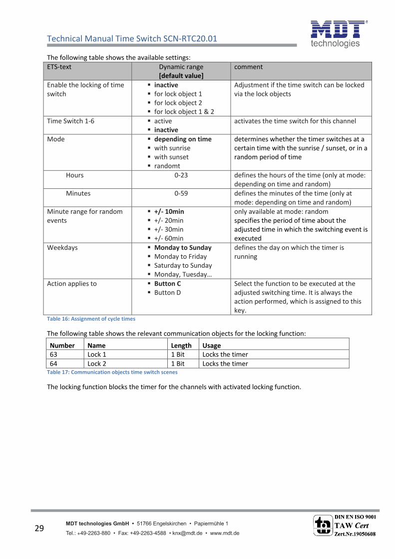
The following table shows the available settings:
ETS-text Dynamic range
[default value]
comment
Enable the locking of time
switch
inactive
for lock object 1
for lock object 2
for lock object 1 & 2
Adjustment if the time switch can be locked
via the lock objects
Time Switch 1-6 active
inactive
activates the time switch for this channel
Mode depending on time
with sunrise
with sunset
randomt
determines whether the timer switches at a
certain time with the sunrise / sunset, or in a
random period of time
Hours 0-23 defines the hours of the time (only at mode:
depending on time and random)
Minutes 0-59 defines the minutes of the time (only at
mode: depending on time and random)
Minute range for random
events
+/- 10min
+/- 20min
+/- 30min
+/- 60min
only available at mode: random
specifies the period of time about the
adjusted time in which the switching event is
executed
Weekdays Monday to Sunday
Monday to Friday
Saturday to Sunday
Monday, Tuesday…
defines the day on which the timer is
running
Action applies to Button C
Button D
Select the function to be executed at the
adjusted switching time. It is always the
action performed, which is assigned to this
key. Table 16: Assignment of cycle times
The following table shows the relevant communication objects for the locking function:
Number Name Length Usage
63 Lock 1 1 Bit Locks the timer
64 Lock 2 1 Bit Locks the timer Table 17: Communication objects time switch scenes
The locking function blocks the timer for the channels with activated locking function.

Technical Manual Time Switch SCN-RTC20.01
MDT technologies GmbH • 51766 Engelskirchen • Papiermühle 1
Tel.: +49-2263-880 • Fax: +49-2263-4588 • [email protected] • www.mdt.de 30
4.5 Controlling the timer on the device
For getting into the menu of the timer, press the left button as long as this menu appears:
Button 1 = Exit the menu
Button 2/3 = Choosing the menu
Button 4 = Calling the menu
In the picture above, button 4 calls the menu to adjust the date and time.
By pressing button 4 in the following setting, all timers are reset:
The cycle times are reset to the values, which are set by the ETS-“oft are. If the para eter “etti g of Ti e “ it h is set to o ly a ual i put ,see: 4.3 , all timers are deactivated.
By pressing button 4 in the following setting, the menu for setting the timers is opened:
At the first step, the fu tio group “ it h, “hutter,… a e selected. By selecting a function group,
all channels are shown, which are sorted into this group. Now, the channel can be selected.
Afterwards the following menu is shown:
By pressing button 4-Edit, the cycle time can be set:
1
2
3 4
1
2 3
4
1
2
3 4

Technical Manual Time Switch SCN-RTC20.01
MDT technologies GmbH • 51766 Engelskirchen • Papiermühle 1
Tel.: +49-2263-880 • Fax: +49-2263-4588 • [email protected] • www.mdt.de 31
1 = Cancel setting
2/3 = Setting in the currently selected menu
4 = select next menu
At setting the cycle time, the following steps are passed:
1.) Setting the days on which the timer is executed.
2.) Set the mode of the timer(time, sunrise, sunset, random, here: time)
3.) Setting the time
4.) Set the action which should be executed
At the mode sunrise, the configuration menu is as follows:
In this example, the timer sends every Thursday 20min after sunrise an On-command.
At the mode random, the configuration menu is as follows:
In this example, the timer sends every Saturday and Sunday between 14:30 and 15:30 an Off-
command.

Technical Manual Time Switch SCN-RTC20.01
MDT technologies GmbH • 51766 Engelskirchen • Papiermühle 1
Tel.: +49-2263-880 • Fax: +49-2263-4588 • [email protected] • www.mdt.de 32
4.6 Logic functions
The following picture shows the available settings for the logic function:
Figure 15: Logic functions
4.6.1 Behavior after rest
The para eter Query logi o je ts after reset is alid for logi A to H a d defi es hether the logi inputs are queried after a reset. The settings have the following meaning:
inactive
The input objects are not queried after a reset and will be initialized with the value 0.
active
The input objects are queried after a reset and accepted with its current value.
Technical Manual Time Switch SCN-RTC20.01
MDT technologies GmbH • 51766 Engelskirchen • Papiermühle 1
Tel.: +49-2263-880 • Fax: +49-2263-4588 • [email protected] • www.mdt.de 33
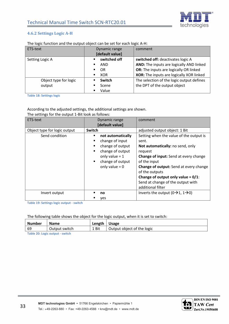
4.6.2 Settings Logic A-H
The logic function and the output object can be set for each logic A-H:
ETS-text Dynamic range
[default value]
comment
Setting Logic A switched off
AND
OR
XOR
switched off: deactivates logic A
AND: The inputs are logically AND linked
OR: The inputs are logically OR linked
XOR: The inputs are logically XOR linked
Object type for logic
output
Switch
Scene
Value
The selection of the logic output defines
the DPT of the output object
Table 18: Settings logic
According to the adjusted settings, the additional settings are shown.
The settings for the output 1-Bit look as follows:
ETS-text Dynamic range
[default value]
comment
Object type for logic output Switch adjusted output object: 1 Bit
Send condition not automatically
change of input
change of output
change of output
only value = 1
change of output
only value = 0
Setting when the value of the output is
sent.
Not automatically: no send, only
request
Change of input: Send at every change
of the input
Change of output: Send at every change
of the outputs
Change of output only value = 0/1:
Send at change of the output with
additional filter
Invert output no
yes
Inverts the output (01, 10)
Table 19: Settings logic output - switch
The following table shows the object for the logic output, when it is set to switch:
Number Name Length Usage
69 Output switch 1 Bit Output object of the logic Table 20: Logic output - switch

Technical Manual Time Switch SCN-RTC20.01
MDT technologies GmbH • 51766 Engelskirchen • Papiermühle 1
Tel.: +49-2263-880 • Fax: +49-2263-4588 • [email protected] • www.mdt.de 34
For a scene output, the settings look as follows:
ETS-text Dynamic range
[default value]
comment
Object type for logic output Scene adjusted output object: Scene
Scene number 1-64
[2]
Adjusting which scene is called after
completing the logic function Table 21: Setting logic output - scene
The following table shows the object which is shown when the logic output is set to scene:
Number Name Length Usage
69 Output scene 1 Byte Output object of the logic Table 22: Logic output - scene
For a byte output, the settings look as follows:
ETS-text Dynamic range
[default value]
comment
Object type for logic output Value adjusted output object: Value
1 Byte-Value 0-255
[0]
Adjusting which value is sent after
completing the logic function Table 23: Setting logic output - value
The following table shows the object which is shown when the logic output is set to 1 Byte value:
Number Name Length Usage
69 Output value 1 Byte Output object of the logic Table 24: Logic output - 1 Byte value

Technical Manual Time Switch SCN-RTC20.01
MDT technologies GmbH • 51766 Engelskirchen • Papiermühle 1
Tel.: +49-2263-880 • Fax: +49-2263-4588 • [email protected] • www.mdt.de 35
4.6.3 Logic inputs
Once a logic module is enabled, a submenu appears in which the inputs can be parameterized for this
logic module.
The following figure shows this menu:
Figure 16: Logic inputs
ETS-text Dynamic range
[default value]
comment
Input logic 1-4 inactive
active - normal
active - inverted
Setting which defines how the input is
evaluated:
inactive: The object for this logic object is
deactivated
active - normal: The object is normal
active
active - inverted: The object is inverted
active (10, 01) Table 25: Settings logic inputs
The following table shows the objects for the logic inputs of logic A:
Number Name Length Usage
65-68 Input logic 1-4 1 Bit Input objects for logic A Table 26: Objects - Input logic

Technical Manual Time Switch SCN-RTC20.01
MDT technologies GmbH • 51766 Engelskirchen • Papiermühle 1
Tel.: +49-2263-880 • Fax: +49-2263-4588 • [email protected] • www.mdt.de 36
5 Index
5.1 List of figures
Figure 1: Exemplary circuit diagram ........................................................................................................ 5
Figure 2: Design & Usage ......................................................................................................................... 5
Figure 3: Menu general settings ............................................................................................................ 15
Figure 4: Menu "Time settings" ............................................................................................................. 16
Figure 5: Menu "Functions of the time-switch" .................................................................................... 20
Figure 6: Menu - Time switch ................................................................................................................ 23
Figure 7: Send value/Send 1 Bit value (On/Off) .................................................................................... 24
Figure 8: Send value/Send 1 Byte value(0..255).................................................................................... 24
Figure 9: Send value/Send HVAC Mode ................................................................................................ 24
Figure 10: Send value/Send temperature value .................................................................................... 25
Figure 11: Key function dimming .......................................................................................................... 25
Figure 12: Function group shutter ......................................................................................................... 26
Figure 13: Function group Scene ........................................................................................................... 27
Figure 14: Assignment of time switches ................................................................................................ 28
Figure 15: Logic functions ...................................................................................................................... 32
Figure 16: Logic inputs ........................................................................................................................... 35

Technical Manual Time Switch SCN-RTC20.01
MDT technologies GmbH • 51766 Engelskirchen • Papiermühle 1
Tel.: +49-2263-880 • Fax: +49-2263-4588 • [email protected] • www.mdt.de 37
5.2 List of tables
Table 1: Overview communication objects - time................................................................................... 9
Table 2: Overview communication objects - time switch ..................................................................... 10
Table 3: Overview communication objects - logic functions ................................................................ 11
Table 4: Default settings of the communication objects - time ............................................................ 12
Table 5: Default settings of the communication objects - time switch ................................................. 13
Table 6: Default settings of the communication objects - logic functions ............................................ 14
Table 7: General settings ....................................................................................................................... 15
Table 8: Settings time ............................................................................................................................ 17
Table 9: Adjustment of the astro function ............................................................................................ 17
Table 10: Communication objects - Date/Time..................................................................................... 18
Table 11: Communication objects - time cycle and cycle program ....................................................... 19
Table 12: Settings Time Switch .............................................................................................................. 21
Table 13: Communication objects time switch-dimming ...................................................................... 25
Table 14: Communication objects time switch - shutter ...................................................................... 26
Table 15: Communication objects time switch - scene ......................................................................... 27
Table 16: Assignment of cycle times ..................................................................................................... 29
Table 17: Communication objects time switch scenes ......................................................................... 29
Table 18: Settings logic .......................................................................................................................... 33
Table 19: Settings logic output - switch ................................................................................................ 33
Table 20: Logic output - switch ............................................................................................................. 33
Table 21: Setting logic output - scene ................................................................................................... 34
Table 22: Logic output - scene ............................................................................................................... 34
Table 23: Setting logic output - value .................................................................................................... 34
Table 24: Logic output - 1 Byte value .................................................................................................... 34
Table 25: Settings logic inputs ............................................................................................................... 35
Table 26: input logic .............................................................................................................................. 35

Technical Manual Time Switch SCN-RTC20.01
MDT technologies GmbH • 51766 Engelskirchen • Papiermühle 1
Tel.: +49-2263-880 • Fax: +49-2263-4588 • [email protected] • www.mdt.de 38
6 Attachment
6.1 Statutory requirements
The above-described devices must not be used with devices, which serve directly or indirectly the
purpose of human, health- or lifesaving. Further the devices must not be used if their usage can
occur danger for humans, animals or material assets.
Do not let the packaging lying around careless, plastic foil/ -bags etc. can be a dangerous toy for kids.
6.2 Routine disposal
Do not throw the waste equipment in the household rubbish. The device contains electrical devices,
which must be disposed as electronic scrap. The casing contains of recyclable synthetic material.
6.3 Assemblage
Risk for life of electrical power!
All activities on the device should only be done by an electrical specialist. The county specific
regulations and the applicable EIB-directives have to be observed.
6.4 Datasheet

SCN-RTC20.01
MDT Time Switch with 20 channels and LCD display, MDRC
Version
SCN-RTC20.01 Time Switch 6SU MDRC, Time Switch with 20 channels. 6 cycle times each channel
MDT Time Switch
The MDT Time switch with 20 channels (6 cycle times each channel) has a daily/weekly/astro switching function and an
adequate power reserve if the bus voltage fails. The cycle times of the single channels are adjustable by the ETS or can
be set directly at the device. The large LCD display for comfortable handling allows direct switching of the 20 channels
(Manual Mode).
The time switch offers cyclic sending of the time on the KNX bus and clock time adjustment by bus telegram (Master-/
slave mode). The 8 logical blocks with 4 inputs each allow individal conjunctions.
The MDT Time Switch is a modular installation device for ixed installation in dry rooms. It its on DIN 35mm rails in power distribution boards or closed compact boxes.
For project design and commissioning of the MDT Time Switch it is recommended to use the ETS.
Please download the application software at www.mdt.de/Downloads.html
• Production in Germany, certiied according to ISO 9001• Time switch with 20 channels (6 cycle times each channel)• Direct switching of the 20 channels (Manual Mode)• Daily/weekly/astro switching function• Large LCD Display• Power reserve• Cycle time adjustable by the ETS and directly at the device• Cyclic sending of the time on the KNX bus (Master)
• Clock time adjustment by bus telegram (Slave)• 8 logical blocks with 4 inputs• Modular installation device for DIN 35mm rails• Integrated bus coupling unit • 3 years warranty
MDT technologies GmbH • 51766 Engelskirchen • Papiermühle 1
Tel.: + 49 - 2263 - 880 • Fax: + 49 - 2263 - 4588 • [email protected] • www.mdt.de
Stand: 0316
DIN EN ISO 9001
TAW Cert
Zert.Nr.1905606
N
MDT Time Switch
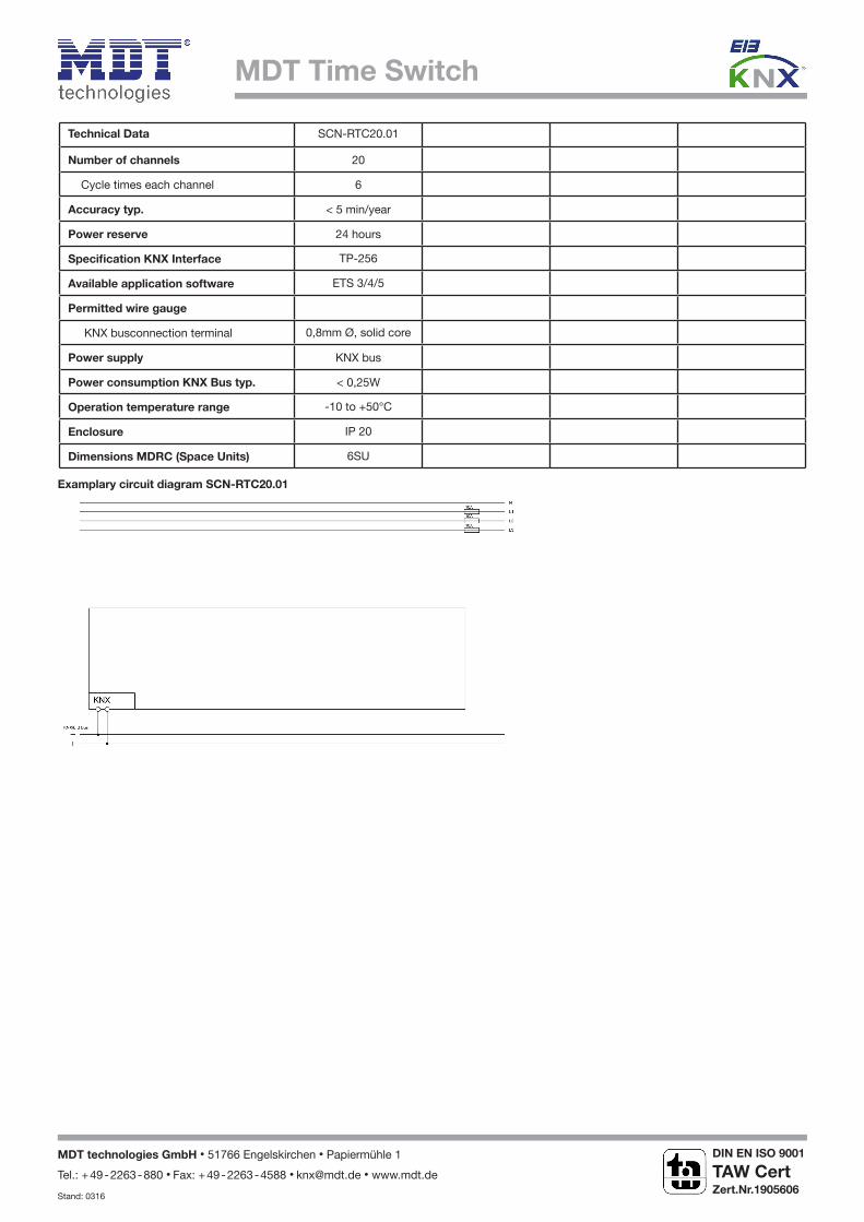
Examplary circuit diagram SCN-RTC20.01
Technical Data SCN-RTC20.01
Number of channels 20
Cycle times each channel 6
Accuracy typ. < 5 min/year
Power reserve 24 hours
Speciication KNX Interface TP-256
Available application software ETS 3/4/5
Permitted wire gauge
KNX busconnection terminal 0,8mm Ø, solid core
Power supply KNX bus
Power consumption KNX Bus typ. < 0,25W
Operation temperature range -10 to +50°C
Enclosure IP 20
Dimensions MDRC (Space Units) 6SU
MDT technologies GmbH • 51766 Engelskirchen • Papiermühle 1
Tel.: + 49 - 2263 - 880 • Fax: + 49 - 2263 - 4588 • [email protected] • www.mdt.de
Stand: 0316
DIN EN ISO 9001
TAW Cert
Zert.Nr.1905606
N