Embed Size (px)
Citation preview

TECHNICAL MANUAL
INSTALLATION, MAINTENANCE AND USE INSTRUCTIONS
ENGLISH

Dear Friends,
This is our first attempt to communicate with you in this manner, where writing becomes a friendly chat. Through the pages of our second enriched publication now in your hands, we present to you our com-pany.
A company offering sunny solutions, working with passion and dedica-tion, for three decades now, to always offer you the best.
HELIOAKMI has been manufacturing and installing solar water heaters since the 1970’s making thousands of loyal friends like you along the way. Our experience in producing highly efficient non-defective prod-ucts economically, makes us justifiably proud of our contribution to society. Because a solar water heater isn’t just a simple appliance that makes our life easier. It is a whole philosophy. A philosophy that has taken HELIOAKMI to the top of the world’s hot water technology from the sun, in over 60 countries, in all climatic conditions and for all types of water qualities.
A philosophy that leads the way and makes us, as professionals, feel the weight of responsibility and obligation to offer products and services that are in harmony with the environment and man. To hand over a better world to our children.
Always true to our principle for excellence in design and continuous advancements, HELIOAKMI today offers high standard solar water heat-ers.
Along with architects, engineers, installers and professionals in this field we can all create together. Using the most economic and efficient technologies available we produce hot water from the sun. For the com-mon good.
We live in “special” times. The environment is sounding the alarm. The whole world is looking towards other renewable energy sources….. The international outcry is raising consciousness… When the answer is right next to us, should we still be searching for it?
Solar water heaters are not a luxury. They are a part of the future, today. The future we promised our children.
Our goal is one. Quality of life. This is our philosophy.
Sincerely yours,
Christos PapadopoulosGeneral Manager
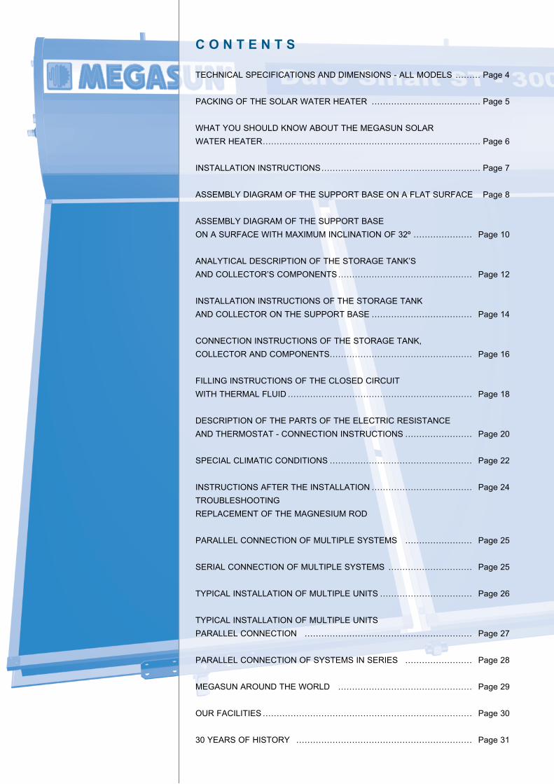
C O N T E N T S
TECHNICAL SPECIFICATIONS AND DIMENSIONS - ALL MODELS ……… Page 4
PACKING OF THE SOLAR WATER HEATER ………………………………… Page 5
WHAT YOU SHOULD KNOW ABOUT THE MEGASUN SOLAR WATER HEATER …………………………………………………………………… Page 6
INSTALLATION INSTRUCTIONS ………………………………………………… Page 7
ASSEMBLY DIAGRAM OF THE SUPPORT BASE ON A FLAT SURFACE Page 8
ASSEMBLY DIAGRAM OF THE SUPPORT BASE ON A SURFACE WITH MAXIMUM INCLINATION OF 32º ………………… Page 10
ANALYTICAL DESCRIPTION OF THE STORAGE TANK’S AND COLLECTOR’S COMPONENTS ………………………………………… Page 12
INSTALLATION INSTRUCTIONS OF THE STORAGE TANK AND COLLECTOR ON THE SUPPORT BASE ……………………………… Page 14
CONNECTION INSTRUCTIONS OF THE STORAGE TANK, COLLECTOR AND COMPONENTS…………………………………………… Page 16
FILLING INSTRUCTIONS OF THE CLOSED CIRCUIT WITH THERMAL FLUID ………………………………………………………… Page 18
DESCRIPTION OF THE PARTS OF THE ELECTRIC RESISTANCE AND THERMOSTAT - CONNECTION INSTRUCTIONS …………………… Page 20
SPECIAL CLIMATIC CONDITIONS …………………………………………… Page 22
INSTRUCTIONS AFTER THE INSTALLATION ……………………………… Page 24TROUBLESHOOTINGREPLACEMENT OF THE MAGNESIUM ROD
PARALLEL CONNECTION OF MULTIPLE SYSTEMS …………………… Page 25
SERIAL CONNECTION OF MULTIPLE SYSTEMS ………………………… Page 25
TYPICAL INSTALLATION OF MULTIPLE UNITS …………………………… Page 26
TYPICAL INSTALLATION OF MULTIPLE UNITS PARALLEL CONNECTION …………………………………………………… Page 27
PARALLEL CONNECTION OF SYSTEMS IN SERIES …………………… Page 28
MEGASUN AROUND THE WORLD ………………………………………… Page 29
OUR FACILITIES ………………………………………………………………… Page 30
30 YEARS OF HISTORY ……………………………………………………… Page 31
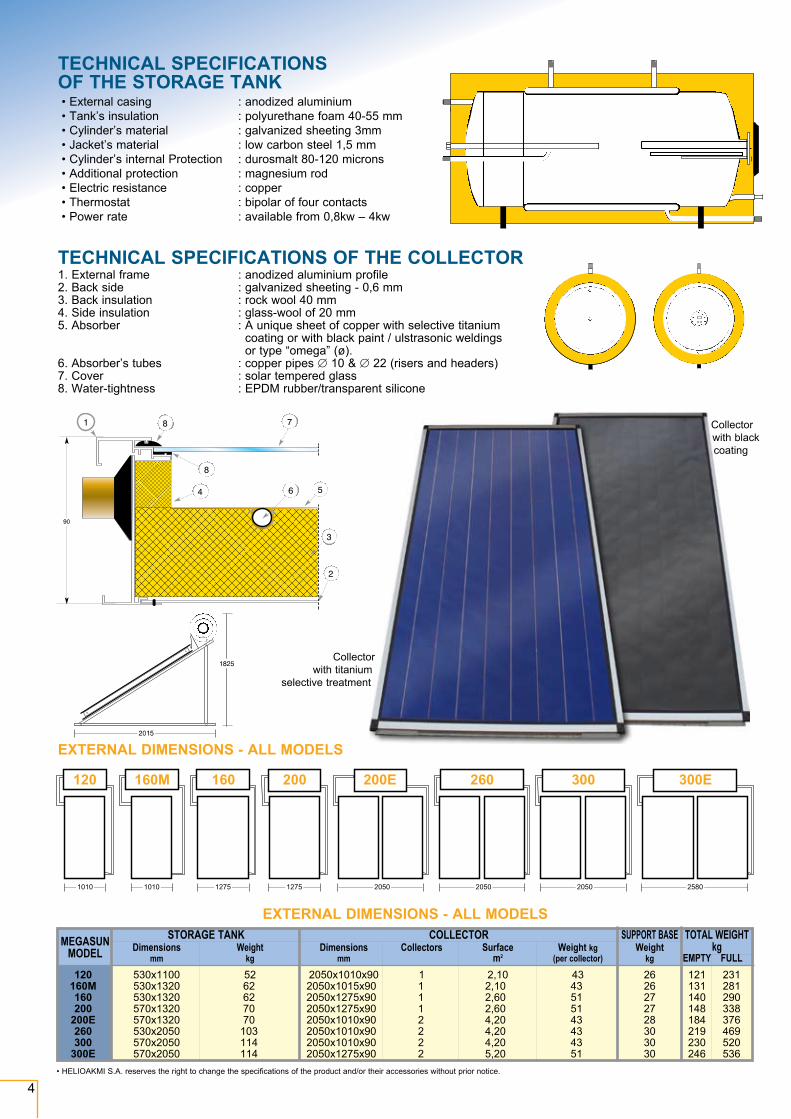
TECHNICAL SPECIFICATIONS OF THE COLLECTOR 1. External frame : anodized aluminium profile 2. Back side : galvanized sheeting - 0,6 mm 3. Back insulation : rock wool 40 mm 4. Side insulation : glass-wool of 20 mm 5. Absorber : A unique sheet of copper with selective titanium
coating or with black paint / ulstrasonic weldings or type “omega” (ø).
6. Absorber’s tubes : copper pipes ∅ 10 & ∅ 22 (risers and headers) 7. Cover : solar tempered glass 8. Water-tightness : EPDM rubber/transparent silicone
4
EXTERNAL DIMENSIONS - ALL MODELS MEGASUN STORAGE TANK COLLECTOR SUPPORT BASE TOTAL WEIGHT MODEL kg Dimensions Weight Dimensions Collectors Surface Weight kg Weight mm kg mm m2 (per collector) kg EMPTY FULL 120 530x1100 52 2050x1010x90 1 2,10 43 26 121 231 160Μ 530x1320 62 2050x1015x90 1 2,10 43 26 131 281 160 530x1320 62 2050x1275x90 1 2,60 51 27 140 290 200 570x1320 70 2050x1275x90 1 2,60 51 27 148 338 200E 570x1320 70 2050x1010x90 2 4,20 43 28 184 376 260 530x2050 103 2050x1010x90 2 4,20 43 30 219 469 300 570x2050 114 2050x1010x90 2 4,20 43 30 230 520 300E 570x2050 114 2050x1275x90 2 5,20 51 30 246 536
• External casing : anodized aluminium • Tank’s insulation : polyurethane foam 40-55 mm • Cylinder’s material : galvanized sheeting 3mm • Jacket’s material : low carbon steel 1,5 mm • Cylinder’s internal Protection : durosmalt 80-120 microns • Additional protection : magnesium rod • Electric resistance : copper • Thermostat : bipolar of four contacts • Power rate : available from 0,8kw – 4kw
TECHNICAL SPECIFICATIONS OF THE STORAGE TANK
• HELIOAKMI S.A. reserves the right to change the specifications of the product and/or their accessories without prior notice.
Collector with titanium
selective treatment
Collector with black coating
EXTERNAL DIMENSIONS - ALL MODELS
1010
120
1275
160
1275
200
2050
200E
2050
260
2050
300
2580
300E
1010
160Μ
Collector with black coating
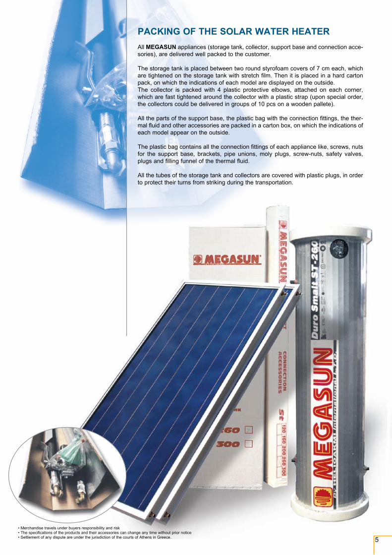
PACKING OF THE SOLAR WATER HEATERAll MEGASUN appliances (storage tank, collector, support base and connection acce-sories), are delivered well packed to the customer.
The storage tank is placed between two round styrofoam covers of 7 cm each, which are tightened on the storage tank with stretch film. Then it is placed in a hard carton pack, on which the indications of each model are displayed on the outside.The collector is packed with 4 plastic protective elbows, attached on each corner, which are fast tightened around the collector with a plastic strap (upon special order, the collectors could be delivered in groups of 10 pcs on a wooden pallete).
All the parts of the support base, the plastic bag with the connection fittings, the ther-mal fluid and other accessories are packed in a carton box, on which the indications of each model appear on the outside.
The plastic bag contains all the connection fittings of each appliance like, screws, nuts for the support base, brackets, pipe unions, moly plugs, screw-nuts, safety valves, plugs and filling funnel of the thermal fluid.
All the tubes of the storage tank and collectors are covered with plastic plugs, in order to protect their turns from striking during the transportation.
• Merchandise travels under buyers responsibility and risk • The specifications of the products and their accessories can change any time without prior notice • Settlement of any dispute are under the jurisdiction of the courts of Athens in Greece. 5
6
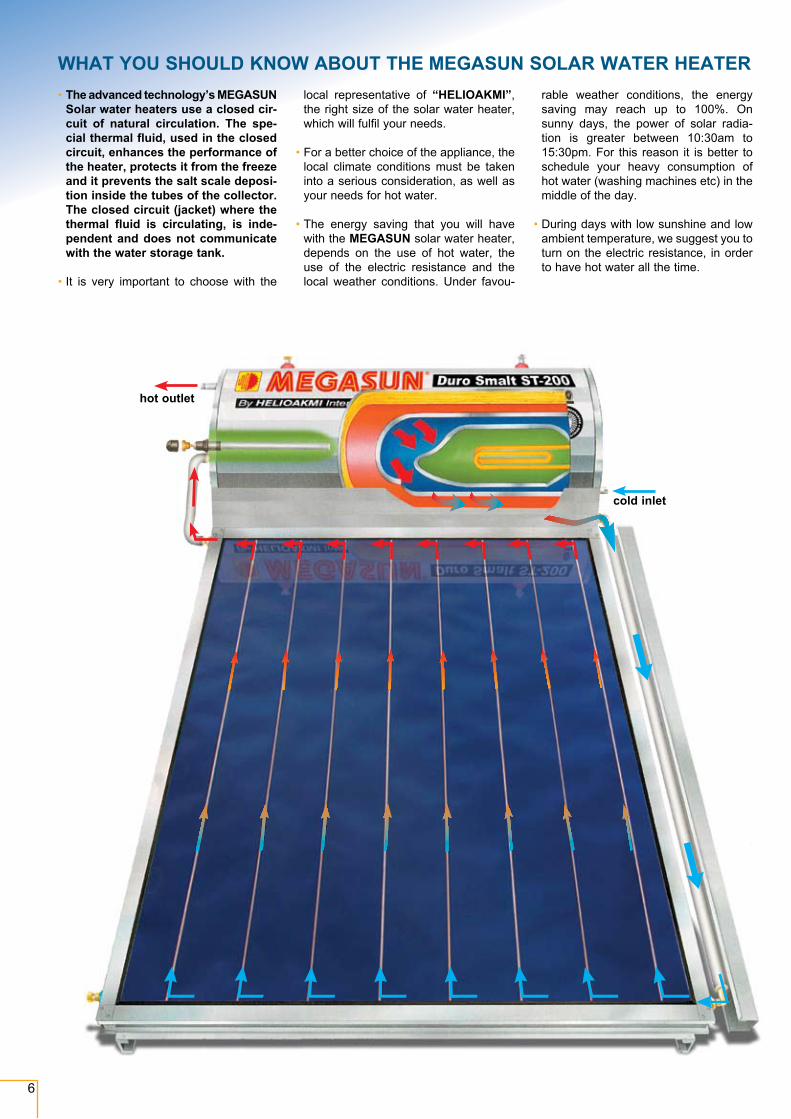
WHAT YOU SHOULD KNOW ABOUT THE MEGASUN SOLAR WATER HEATER• The advanced technology’s MEGASUN
Solar water heaters use a closed cir-cuit of natural circulation. The spe-cial thermal fluid, used in the closed circuit, enhances the performance of the heater, protects it from the freeze and it prevents the salt scale deposi-tion inside the tubes of the collector. The closed circuit (jacket) where the thermal fluid is circulating, is inde-pendent and does not communicate with the water storage tank.
• It is very important to choose with the
local representative of “HELIOAKMI”, the right size of the solar water heater, which will fulfil your needs.
• For a better choice of the appliance, the local climate conditions must be taken into a serious consideration, as well as your needs for hot water.
• The energy saving that you will have with the MEGASUN solar water heater, depends on the use of hot water, the use of the electric resistance and the local weather conditions. Under fa vou-
rable weather conditions, the energy saving may reach up to 100%. On sunny days, the power of solar radia-tion is greater between 10:30am to 15:30pm. For this reason it is better to schedule your heavy consumption of hot water (washing machines etc) in the middle of the day.
• During days with low sunshine and low ambient temperature, we suggest you to turn on the electric resistance, in order to have hot water all the time.
hot outlet
cold inlet
WHAT YOU SHOULD KNOW ABOUT THE MEGASUN SOLAR WATER HEATER
7
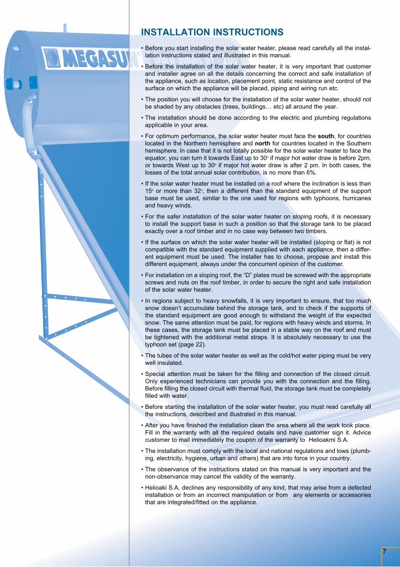
INSTALLATION INSTRUCTIONS• Before you start installing the solar water heater, please read carefully all the instal-
lation instructions stated and illustrated in this manual.
• Before the installation of the solar water heater, it is very important that customer and installer agree on all the details concerning the correct and safe installation of the appliance, such as location, placement point, static resistance and control of the surface on which the appliance will be placed, piping and wiring run etc.
• The position you will choose for the installation of the solar water heater, should not be shaded by any obstacles (trees, buildings… etc) all around the year.
• The installation should be done according to the electric and plumbing regulations applicable in your area.
• For optimum performance, the solar water heater must face the south, for countries located in the Northern hemisphere and north for countries located in the Southern hemisphere. In case that it is not totally possible for the solar water heater to face the equator, you can turn it towards East up to 30o if major hot water draw is before 2pm, or towards West up to 30o if major hot water draw is after 2 pm. In both cases, the losses of the total annual solar contribution, is no more than 6%.
• If the solar water heater must be installed on a roof where the inclination is less than 15o or more than 32o, then a different than the standard equipment of the support base must be used, similar to the one used for regions with typhoons, hurricanes and heavy winds.
• For the safer installation of the solar water heater on sloping roofs, it is necessary to install the support base in such a position so that the storage tank to be placed exactly over a roof timber and in no case way between two timbers.
• If the surface on which the solar water heater will be installed (sloping or flat) is not compatible with the standard equipment supplied with each appliance, then a differ-ent equipment must be used. The installer has to choose, propose and install this different equipment, always under the concurrent opinion of the customer.
• For installation on a sloping roof, the “D” plates must be screwed with the appropriate screws and nuts on the roof timber, in order to secure the right and safe installation of the solar water heater.
• In regions subject to heavy snowfalls, it is very important to ensure, that too much snow doesn’t accumulate behind the storage tank, and to check if the supports of the standard equipment are good enough to withstand the weight of the expected snow. The same attention must be paid, for regions with heavy winds and storms. In these cases, the storage tank must be placed in a stable way on the roof and must be tightened with the additional metal straps. It is absolutely necessary to use the typhoon set (page 22).
• The tubes of the solar water heater as well as the cold/hot water piping must be very well insulated.
• Special attention must be taken for the filling and connection of the closed circuit. Only experienced technicians can provide you with the connection and the filling. Before filling the closed circuit with thermal fluid, the storage tank must be completely filled with water.
• Before starting the installation of the solar water heater, you must read carefully all the instructions, described and illustrated in this manual.
• After you have finished the installation clean the area where all the work took place. Fill in the warranty with all the required details and have customer sign it. Advice customer to mail immediately the coupon of the warranty to Helioakmi S.A.
• The installation must comply with the local and national regulations and lows (plumb-ing, electricity, hygiene, urban and others) that are into force in your country.
• The observance of the instructions stated on this manual is very important and the non-observance may cancel the validity of the warranty.
• Helioaki S.A. declines any responsibility of any kind, that may arise from a defected installation or from an incorrect manipulation or from any elements or accessories that are integrated/fitted on the appliance.
A
U
D
D
C
EZ Z
B
F
8
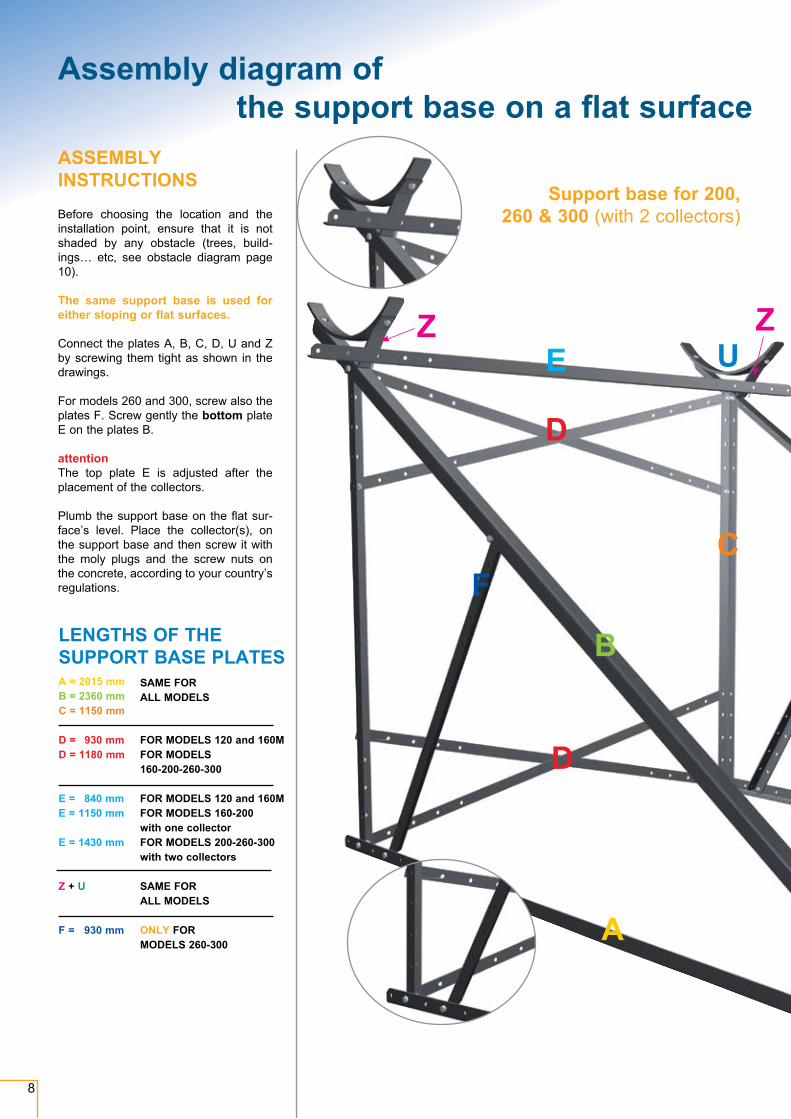
A = 2015 mmB = 2360 mmC = 1150 mm
D = 930 mmD = 1180 mm
E = 840 mmE = 1150 mm
E = 1430 mm
Z + U
F = 930 mm
SAME FOR ALL MODELS
FOR MODELS 120 and 160MFOR MODELS 160-200-260-300
FOR MODELS 120 and 160MFOR MODELS 160-200 with one collectorFOR MODELS 200-260-300 with two collectors
SAME FOR ALL MODELS
ONLY FOR MODELS 260-300
LENGTHS OF THE SUPPORT BASE PLATES
ASSEMBLY INSTRUCTIONSBefore choosing the location and the installation point, ensure that it is not shaded by any obstacle (trees, build-ings… etc, see obstacle diagram page 10).
The same support base is used for either sloping or flat surfaces.
Connect the plates A, B, C, D, U and Z by screwing them tight as shown in the drawings.
For models 260 and 300, screw also the plates F. Screw gently the bottom plate E on the plates B.
attentionThe top plate E is adjusted after the placement of the collectors.
Plumb the support base on the flat sur-face’s level. Place the collector(s), on the support base and then screw it with the moly plugs and the screw nuts on the concrete, according to your country’s regulations.
Support base for 200, 260 & 300 (with 2 collectors)
Assembly diagram of the support base on a flat surface
9
A
B
E
F
A
U
U
C
D
D
C
EZ
A
B
E
B
Z
D
E
EU Z
A
BC F
9
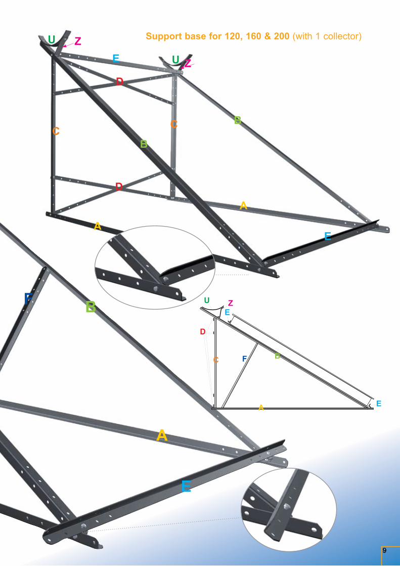
Support base for 120, 160 & 200 (with 1 collector)
10
Assembly diagram of the support base on a surface with maximum inclination of 320
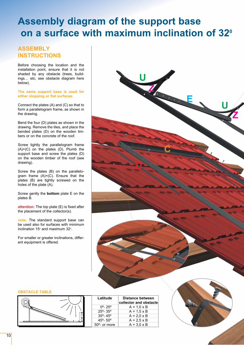
ASSEMBLY INSTRUCTIONS Before choosing the location and the installation point, ensure that it is not shaded by any obstacle (trees, build-ings… etc, see obstacle diagram here below).
The same support base is used for either slopping or flat surfaces.
Connect the plates (A) and (C) so that to form a parallelogram frame, as shown in the drawing.
Bend the four (D) plates as shown in the drawing. Remove the tiles, and place the bended plates (D) on the wooden tim-bers or on the concrete of the roof.
Screw tightly the parallelogram frame (A)+(C) on the plates (D). Plumb the support base and screw the plates (D) on the wooden timber of the roof (see drawing).
Screw the plates (B) on the parallelo-gram frame (A)+(C). Ensure that the plates (B) are tightly screwed on the holes of the plate (A).
Screw gently the bottom plate E on the plates B.
attention: The top plate (E) is fixed after the placement of the collector(s).
note: The standard support base can be used also for surfaces with minimum inclination 15o and maximum 32o.
For smaller or greater inclinations, differ-ent equipment is offered.
OBSTACLE TABLE
Latitude Distance between collector and obstacle 0º- 25º A = 1,0 x B 25º- 35º A = 1,5 x B 35º- 45º A = 2,0 x B 45º- 50º A = 2,5 x B 50º- or more A = 3,0 x B
A
CD
D
C
E
A
BB
E
ZU
UZ
11
A
CD
D
C
E
A
BB
E
ZU
UZ
A
U
U
C
D
D
C
EZ
A
B
E
B
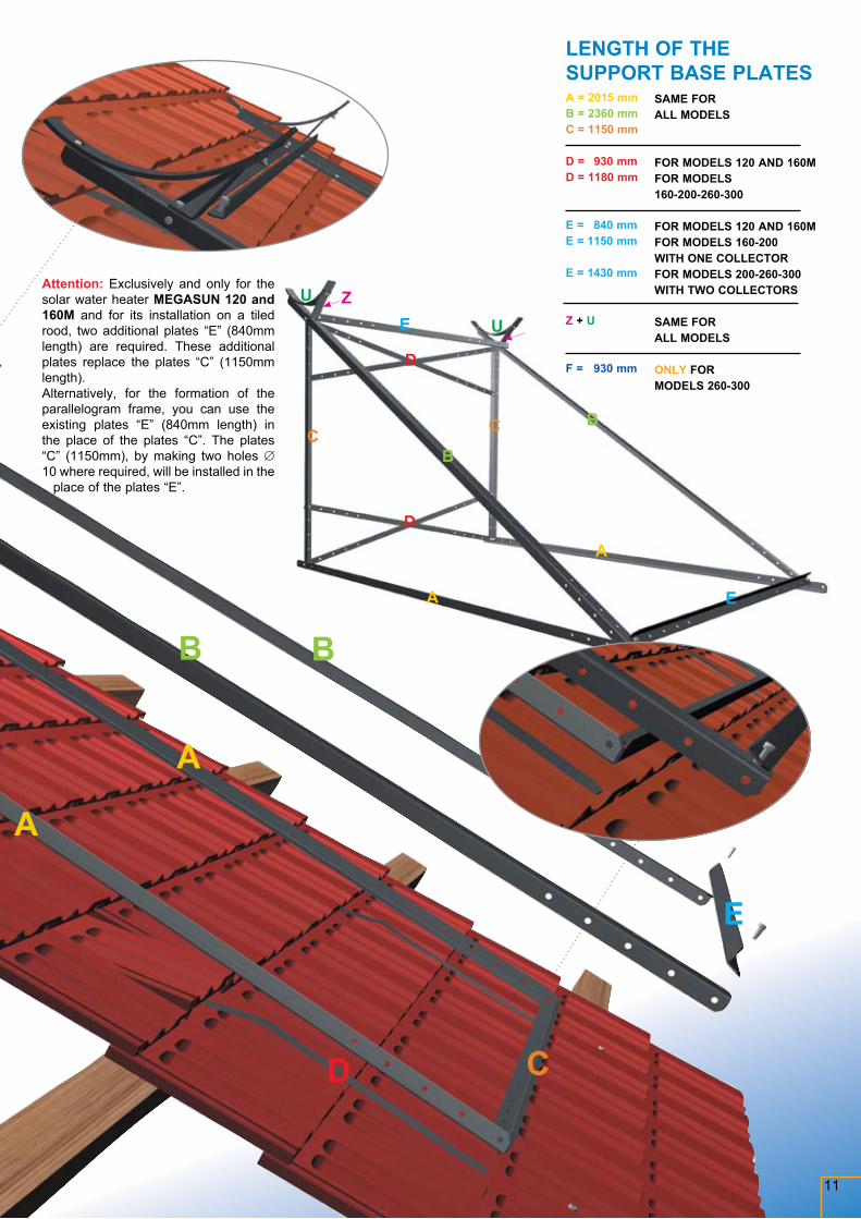
Attention: Exclusively and only for the solar water heater MEGASUN 120 and 160M and for its installation on a tiled rood, two additional plates “E” (840mm length) are required. These additional plates replace the plates “C” (1150mm length). Alternatively, for the formation of the parallelogram frame, you can use the existing plates “E” (840mm length) in the place of the plates “C”. The plates “C” (1150mm), by making two holes ∅ 10 where required, will be installed in the
place of the plates “E”.
A = 2015 mmB = 2360 mmC = 1150 mm
D = 930 mmD = 1180 mm
E = 840 mmE = 1150 mm
E = 1430 mm
Z + U
F = 930 mm
SAME FOR ALL MODELS
FOR MODELS 120 AND 160MFOR MODELS 160-200-260-300
FOR MODELS 120 AND 160MFOR MODELS 160-200 WITH ONE COLLECTORFOR MODELS 200-260-300 WITH TWO COLLECTORS
SAME FOR ALL MODELS
ONLY FOR MODELS 260-300
LENGTH OF THE SUPPORT BASE PLATES
01
02A
02
11
12
03
04
13A
07
07
05A
01A01B
08
09A
09
01C
09B
10
05
06
13
12
13
03
03
0307
19
07
12
Analytical description of the storage tank’s and collector’s components
14A
14
16
07
18
20A
20
14A
15
15A
15A03
14
17A
17A
17
19
07
03
13
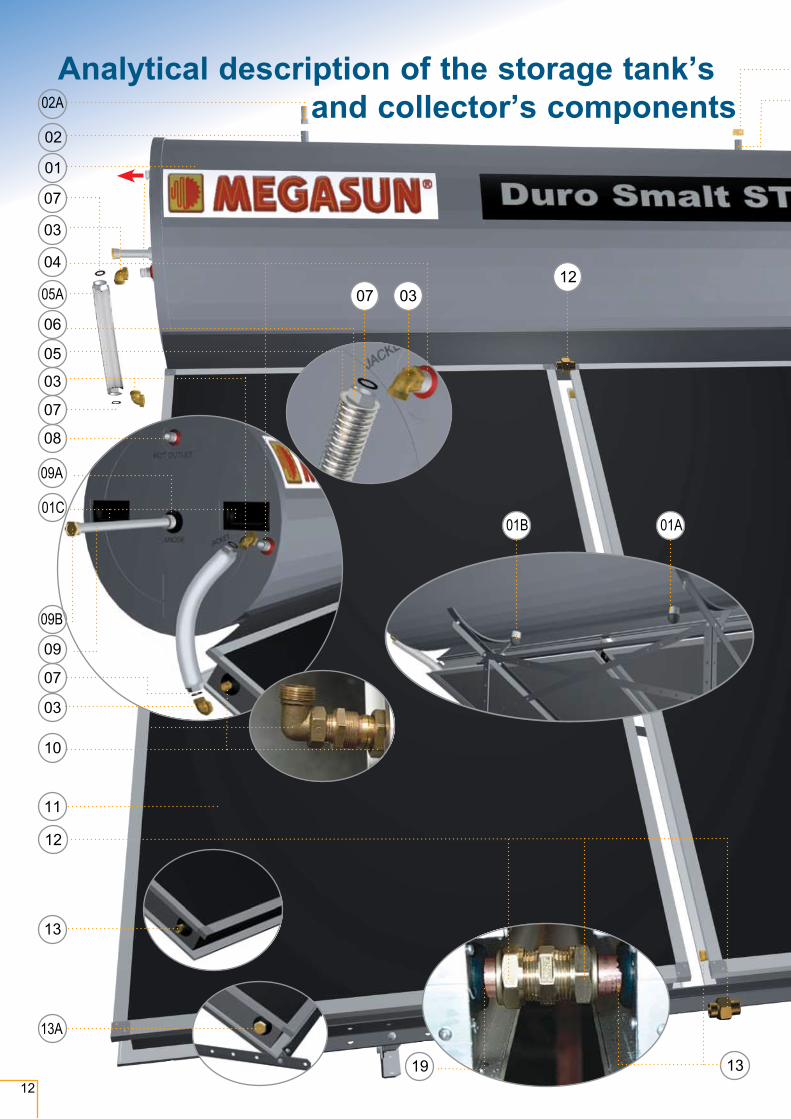
01 Storage tank01A+B Storage tank’s suspension point
(used only in production process, ignore them)
01C Handles
02 Filling pipe (for the closed circuit)02A Safety valve 3 BAR
03 Elbow raccord (4 pcs)
04 Thermal fluid inlet pipe (to the stor-age tank from the collector) (indica-tion “jacket”)
05 Small connection tube 05A Insulated cover of the small con-
nection tube
06 Raccord
07 Water-tight compression ring (4 pcs).
08 Hot water outlet pipe for home consumption (indication: “hot outlet”)
09 Magnesium rod09A Magnesium rod socket09B Magnesium rod’s plug (ó”)
10 Thermal fluid outlet pipe (from the collector to the storage tank)
11 Collector(s)
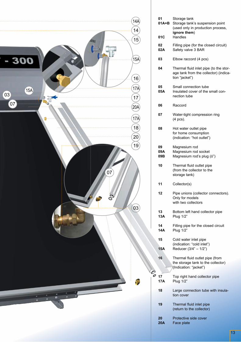
12 Pipe unions (collector connectors). Only for models with two collectors
13 Bottom left hand collector pipe13A Plug 1/2”
14 Filling pipe for the closed circuit14A Plug 1/2”
15 Cold water inlet pipe (indication: “cold inlet”)
15A Reducer (3/4” – 1/2”)
16 Thermal fluid outlet pipe (from the storage tank to the collector) (Indication: “jacket”)
17 Top right hand collector pipe17A Plug 1/2”
18 Large connection tube with insula-tion cover
19 Thermal fluid inlet pipe (return to the collector)
20 Protective side cover20A Face plate
14
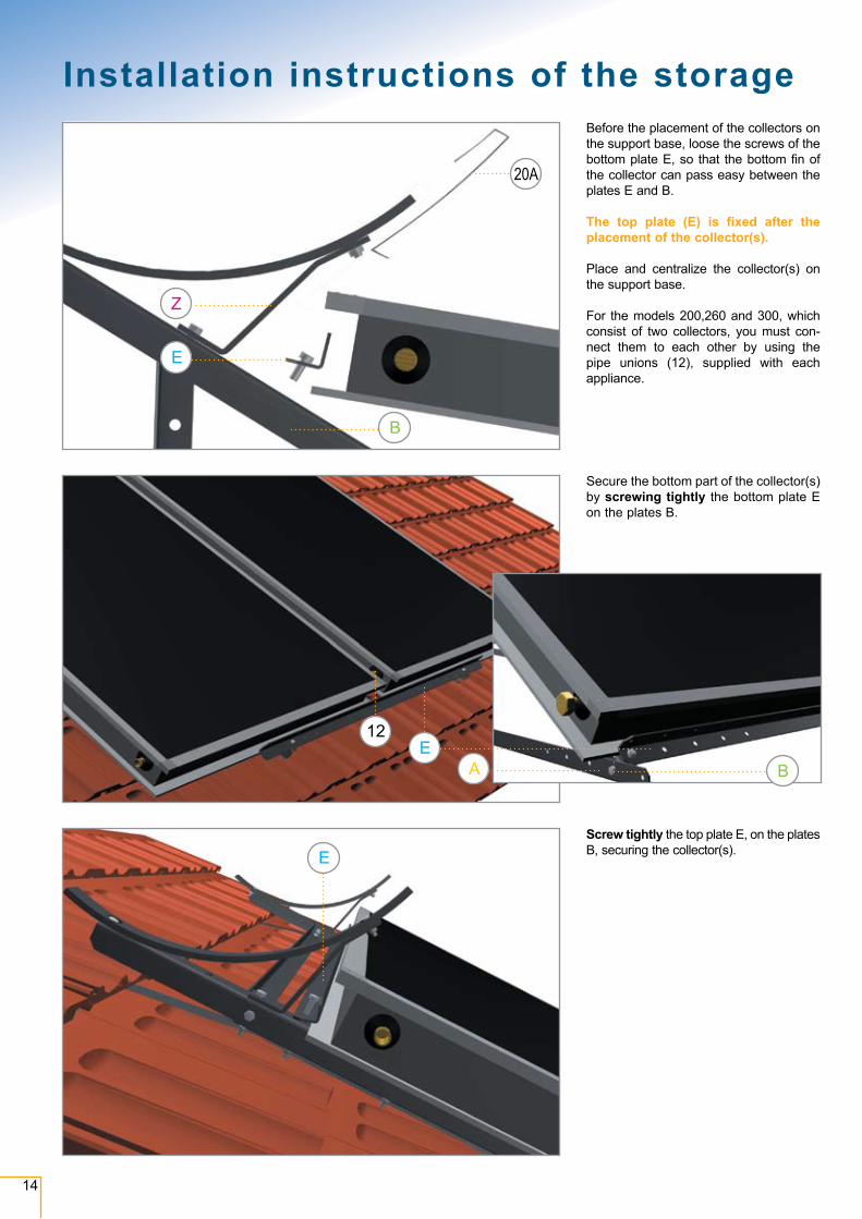
Before the placement of the collectors on the support base, loose the screws of the bottom plate E, so that the bottom fin of the collector can pass easy between the plates E and B.
The top plate (E) is fixed after the placement of the collector(s).
Place and centralize the collector(s) on the support base.
For the models 200,260 and 300, which consist of two collectors, you must con-nect them to each other by using the pipe unions (12), supplied with each appliance.
Secure the bottom part of the collector(s) by screwing tightly the bottom plate E on the plates B.
Screw tightly the top plate E, on the plates B, securing the collector(s).
EA
12
E
B
E
Z
B
20A
Installation instructions of the storage tank and collector on the support base
15
Installation instructions of the storage tank and collector on the support base
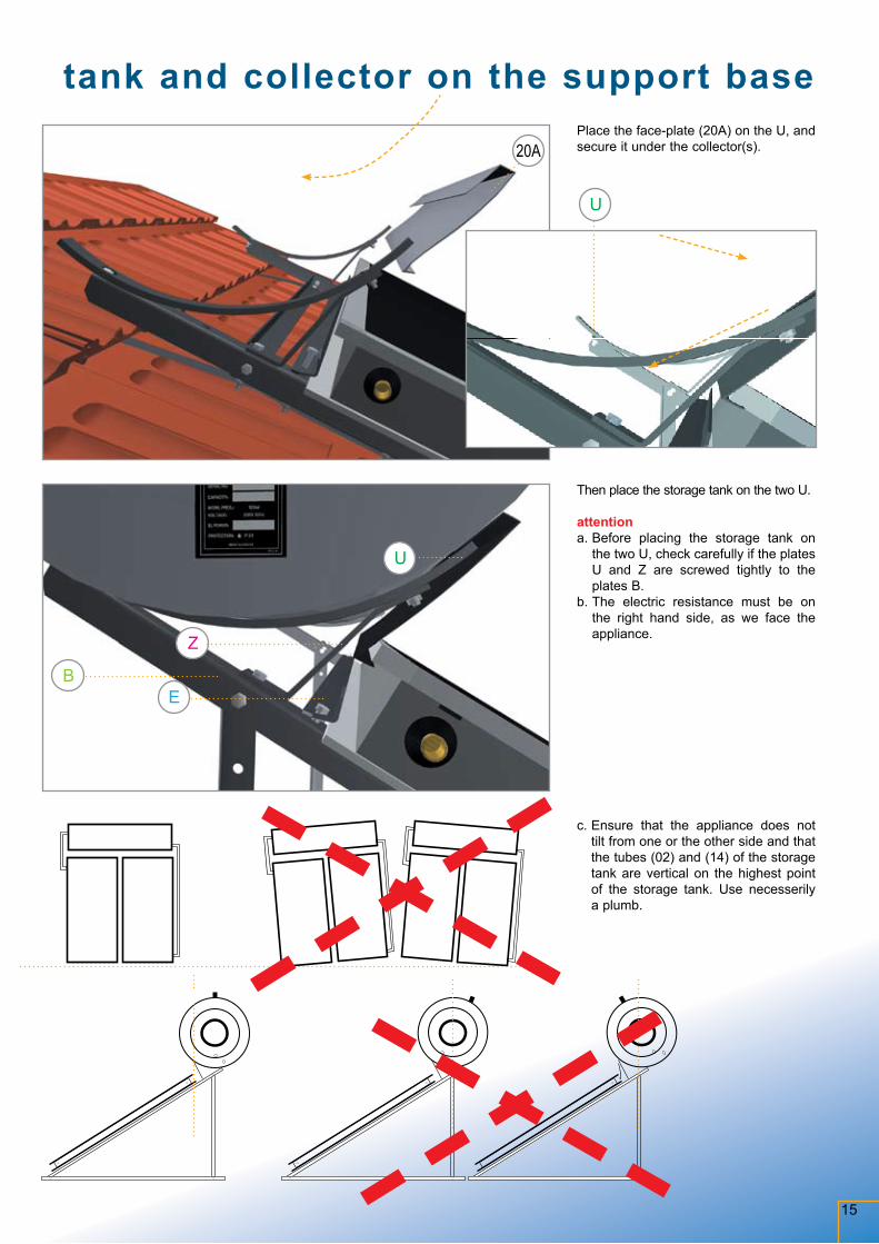
Then place the storage tank on the two U.
attentiona. Before placing the storage tank on
the two U, check carefully if the plates U and Z are screwed tightly to the plates B.
b. The electric resistance must be on the right hand side, as we face the appliance.
c. Ensure that the appliance does not tilt from one or the other side and that the tubes (02) and (14) of the storage tank are vertical on the highest point of the storage tank. Use necesserily a plumb.
Z
BE
U
Place the face-plate (20A) on the U, and secure it under the collector(s).
U
20A
16
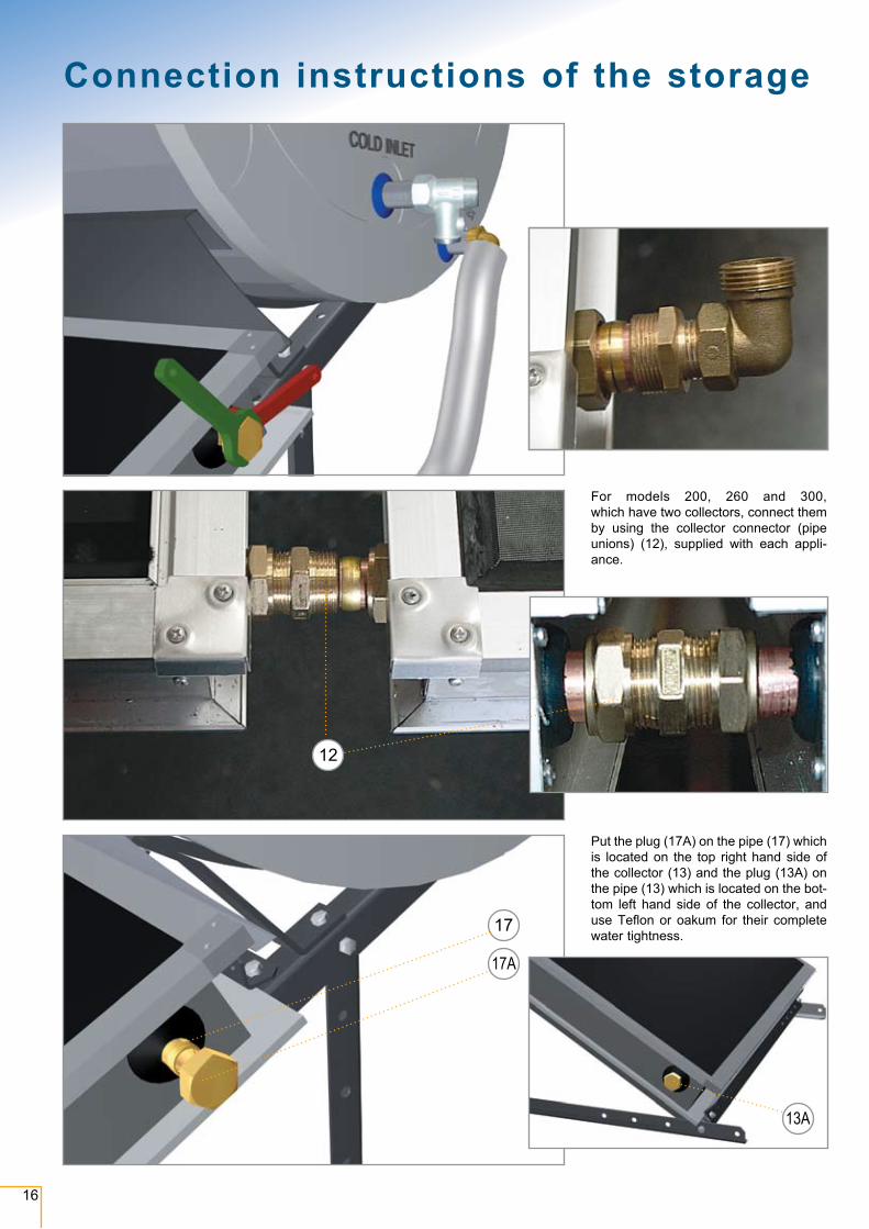
Put the plug (17A) on the pipe (17) which is located on the top right hand side of the collector (13) and the plug (13A) on the pipe (13) which is located on the bot-tom left hand side of the collector, and use Teflon or oakum for their complete water tightness.
For models 200, 260 and 300, which have two collectors, connect them by using the collector connector (pipe unions) (12), supplied with each appli-ance.
17
17A
13A
12
Connection instructions of the storage tank, collector and components
17
03
1816
15 15A
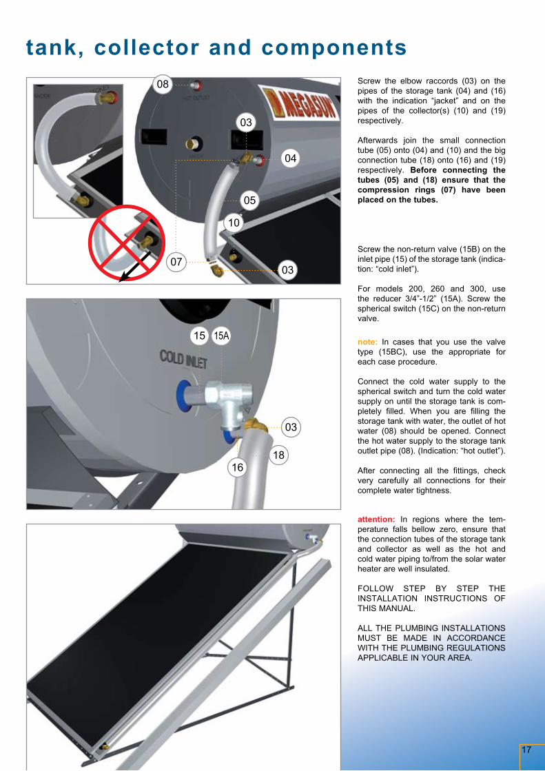
Screw the elbow raccords (03) on the pipes of the storage tank (04) and (16) with the indication “jacket” and on the pipes of the collector(s) (10) and (19) respectively.
Afterwards join the small connection tube (05) onto (04) and (10) and the big connection tube (18) onto (16) and (19) respectively. Before connecting the tubes (05) and (18) ensure that the compression rings (07) have been placed on the tubes.
Screw the non-return valve (15B) on the inlet pipe (15) of the storage tank (indica-tion: “cold inlet”).
For models 200, 260 and 300, use the reducer 3/4”-1/2” (15A). Screw the spherical switch (15C) on the non-return valve.
note: In cases that you use the valve type (15BC), use the appropriate for each case procedure.
Connect the cold water supply to the spherical switch and turn the cold water supply on until the storage tank is com-pletely filled. When you are filling the storage tank with water, the outlet of hot water (08) should be opened. Connect the hot water supply to the storage tank outlet pipe (08). (Indication: “hot outlet”).
After connecting all the fittings, check very carefully all connections for their complete water tightness.
attention: In regions where the tem-perature falls bellow zero, ensure that the connection tubes of the storage tank and collector as well as the hot and cold water piping to/from the solar water heater are well insulated.
FOLLOW STEP BY STEP THE INSTALLATION INSTRUCTIONS OF THIS MANUAL.
ALL THE PLUMBING INSTALLATIONS MUST BE MADE IN ACCORDANCE WITH THE PLUMBING REGULATIONS APPLICABLE IN YOUR AREA.
Connection instructions of the storage tank, collector and components
03
0307
05
08
04
10

1402A
14A02
18
For antifreeze protection of the solar water heater, please follow
the ratio of antifreeze protection stated in the table here below.
Mix well the thermal fluid with water.
Start filling the closed circuit with the mixture, from the pipes (14)
and (02).
The filling must be done alternatively, from both pipes (14) and (02).
During the filling, we advice you to shake the system, so that to ensure that no air is trapped inside
the storage tank and the collector.
Continue this procedure until the close circuit is completely
full.
The responsibility for the cor-rect use of the antifreeze liquid
quantity is for the account of the installer and in no case of Helioakmi
S.A.
The use of water only or other liquid may cancel the validity of the warranty.
ANTIFREEZE PROTECTION RATIO TABLE FOR SOLAR WATER HEATERS
Please take into account also to the dilution table on the bottle of the antifreeze liquid.
Filling Instructions of the Closed Circuit with Thermal Fluid (for the solar water heaters of closed circuit)
MODELMEGASUN ΜΕGASUN MEGASUN MEGASUN MEGASUN MEGASUN MEGASUN MEGASUN
120 x 2.10m2 160 x 2,10m2 160 x 2.60m2 200 x 2.60m2 200E x 4.20m2 260 x 4.20m2 300 x 4.20m2 300E x 5m2
CLOSED CIRCUIT TOTAL CAPACITY 9 lt 10 lt. 11 lt 13 lt 18 lt 21 lt 22 lt 23 lt
TEMPERATURE RATIO
- 5ºCWater 8 lt 9 lt 10 lt 11,5 lt 16 lt 19 lt 19,5 lt 20,5 lt
Fluid 1 lt 1 lt 1 lt 1,5 lt 2 lt 2 lt 2,5 lt 2,5 lt
- 11ºCWater 7 lt 8 lt 9 lt 10,5 lt 14,5 lt 16,5 lt 17,5 lt 18,5 lt
Fluid 2 lt 2 lt 2 lt 2,5 lt 3,5 lt 4,5 lt 4,5 lt 4,5 lt
- 18ºCWater 6 lt 6,5 lt 7,5 lt 9 lt 12,5 lt 14,5 lt 15,5 lt 16 lt
Fluid 3 lt 3,5 lt 3,5 lt 4 lt 5,5 lt 6,5 lt 6,5 lt 7 lt
- 20ºCWater 6 lt 6,5 lt 7,5 lt 9 lt 12 lt 14 lt 14,5 lt 15,5 lt
Fluid 3 lt 3,5 lt 3,5 lt 4 lt 6 lt 7 lt 7,5 lt 7,5 lt
- 27ºCWater 5,5 lt 5,5 lt 6,5 lt 7,5 lt 10,5 lt 12,5 lt 13 lt 13,5 lt
Fluid 3,5 lt 4,5 lt 4,5 lt 5,5 lt 7,5 lt 8,5 lt 9 lt 9,5 lt
- 36ºCWater 4,5 lt 5 lt 5,5 lt 6,5 lt 9 lt 10,5 lt 11 lt 11,5 lt
Fluid 4,5 lt 5 lt 5,5 lt 6,5 lt 9 lt 10,5 lt 11 lt 11,5 lt
1402A
14A02
1919
20
17A
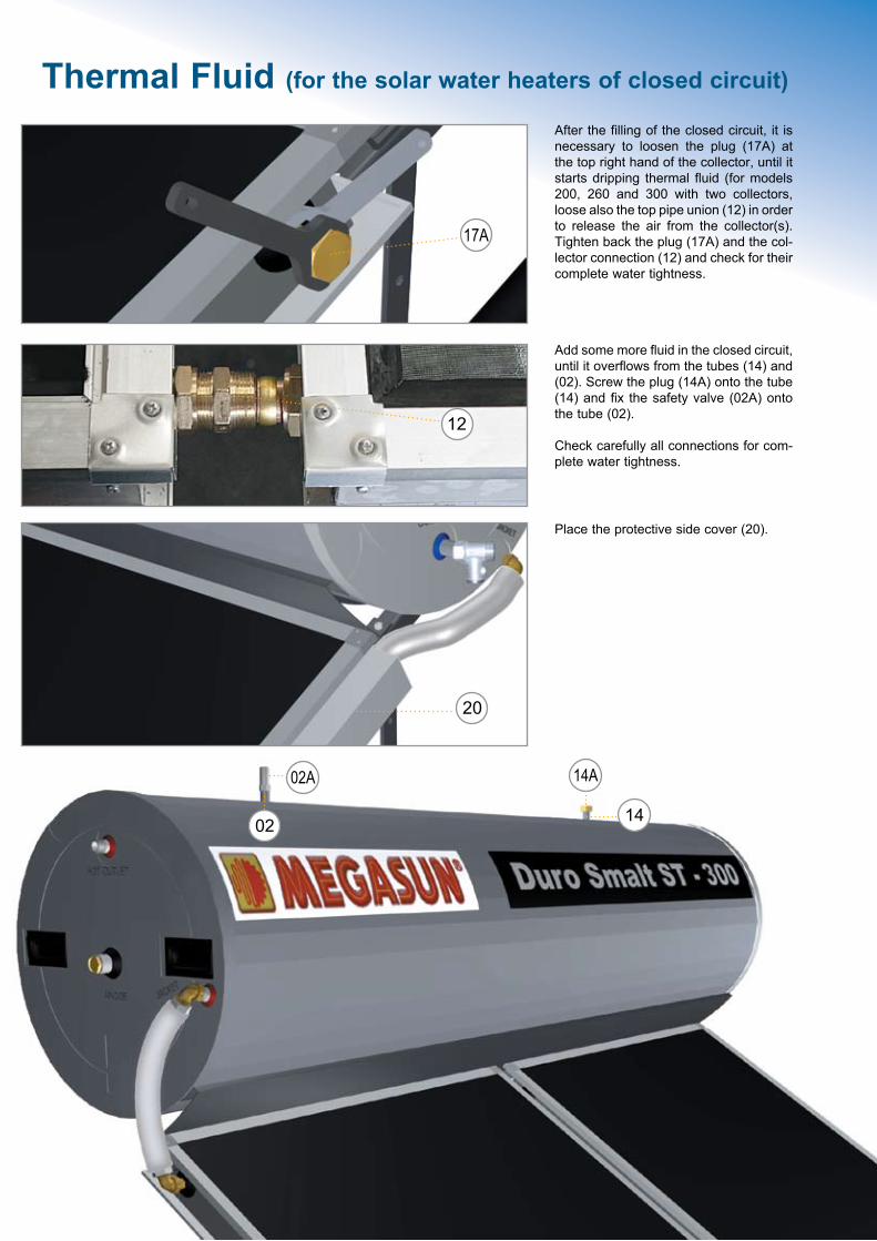
After the filling of the closed circuit, it is necessary to loosen the plug (17A) at the top right hand of the collector, until it starts dripping thermal fluid (for models 200, 260 and 300 with two collectors, loose also the top pipe union (12) in order to release the air from the collector(s). Tighten back the plug (17A) and the col-lector connection (12) and check for their complete water tightness.
Place the protective side cover (20).
12
Add some more fluid in the closed circuit, until it overflows from the tubes (14) and (02). Screw the plug (14A) onto the tube (14) and fix the safety valve (02A) onto the tube (02).
Check carefully all connections for com-plete water tightness.
Filling Instructions of the Closed Circuit with Thermal Fluid (for the solar water heaters of closed circuit)
14
02A 14A
02
20
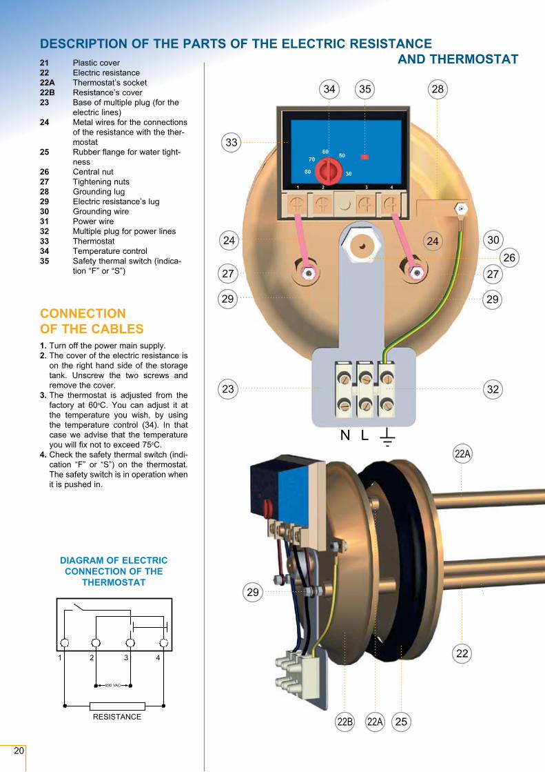
DESCRIPTION OF THE PARTS OF THE ELECTRIC RESISTANCE AND THERMOSTAT21 Plastic cover
22 Electric resistance22A Thermostat’s socket 22B Resistance’s cover23 Base of multiple plug (for the
electric lines)24 Metal wires for the connections
of the resistance with the ther-mostat
25 Rubber flange for water tight-ness
26 Central nut27 Tightening nuts28 Grounding lug29 Electric resistance’s lug30 Grounding wire31 Power wire32 Multiple plug for power lines33 Thermostat34 Temperature control35 Safety thermal switch (indica-
tion “F” or “S”)
CONNECTION OF THE CABLES1. Turn off the power main supply.2. The cover of the electric resistance is
on the right hand side of the storage tank. Unscrew the two screws and remove the cover.
3. The thermostat is adjusted from the factory at 60oC. You can adjust it at the temperature you wish, by using the temperature control (34). In that case we advise that the temperature you will fix not to exceed 75oC.
4. Check the safety thermal switch (indi-cation “F” or “S”) on the thermostat. The safety switch is in operation when it is pushed in.
DIAGRAM OF ELECTRIC CONNECTION OF THE
THERMOSTAT29
22A
22B 22A
22
25
28
26
34 35
33
24
27
32
24
27
2929
23
30
1 2 3 4
30
5060
70
80
N L
230 VAC
1 2 3 4
RΕSISTAnCE
21
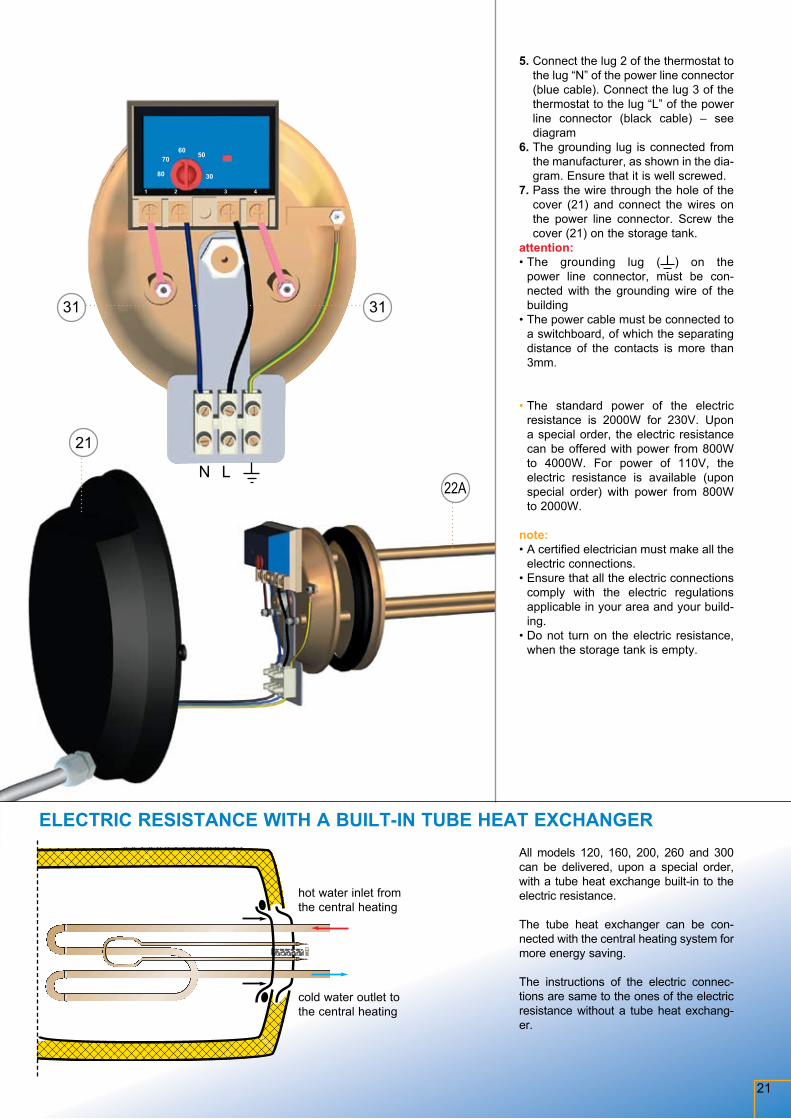
5. Connect the lug 2 of the thermostat to the lug “N” of the power line connector (blue cable). Connect the lug 3 of the thermostat to the lug “L” of the power line connector (black cable) – see diagram
6. The grounding lug is connected from the manufacturer, as shown in the dia-gram. Ensure that it is well screwed.
7. Pass the wire through the hole of the cover (21) and connect the wires on the power line connector. Screw the cover (21) on the storage tank.
attention: • The grounding lug ( ) on the
power line connector, must be con-nected with the grounding wire of the building
• The power cable must be connected to a switchboard, of which the separating distance of the contacts is more than 3mm.
• The standard power of the electric resistance is 2000W for 230V. Upon a special order, the electric resistance can be offered with power from 800W to 4000W. For power of 110V, the electric resistance is available (upon special order) with power from 800W to 2000W.
note: • A certified electrician must make all the
electric connections.• Ensure that all the electric connections
comply with the electric regulations applicable in your area and your build-ing.
• Do not turn on the electric resistance, when the storage tank is empty.
All models 120, 160, 200, 260 and 300 can be delivered, upon a special order, with a tube heat exchange built-in to the electric resistance.
The tube heat exchanger can be con-nected with the central heating system for more energy saving.
The instructions of the electric connec-tions are same to the ones of the electric resistance without a tube heat exchang-er.
ELECTRIC RESISTANCE WITH A BUILT-IN TUBE HEAT EXCHANGER
hot water inlet from the central heating
cold water outlet to the central heating
29
22A
22B 22A
22
25
21
22A
31 31
1 2 3 4
N L
30
5060
70
80
22
In regions where heavy winds, typhoons, hurricanes and storms are usual, it is necessary to use the special TYPHOON SET, provided by HELIOAKMI.
The typhoon set contains:1. Plates (J) of 1150mm2. Plates (D) of 930 mm3. Short fixing plates (L)
4. Long screws - small step nuts5. Tape of metal belt.6. Rubber profile7. Moly plugs - screw nuts
Before you start installing the appliance, you should check the following:
• For installation on a flat surface, check
the density, hardness and strength of the concrete.
• For installation on a sloping roof, addi-tional rafters must be installed under the tiles, so that the distance between the rafters doesn’t exceed 50 cm, and their strength must be good enough for the safe installation of the appliance.
S p e c i a l c l i m a t i c c o n d i t i o n s
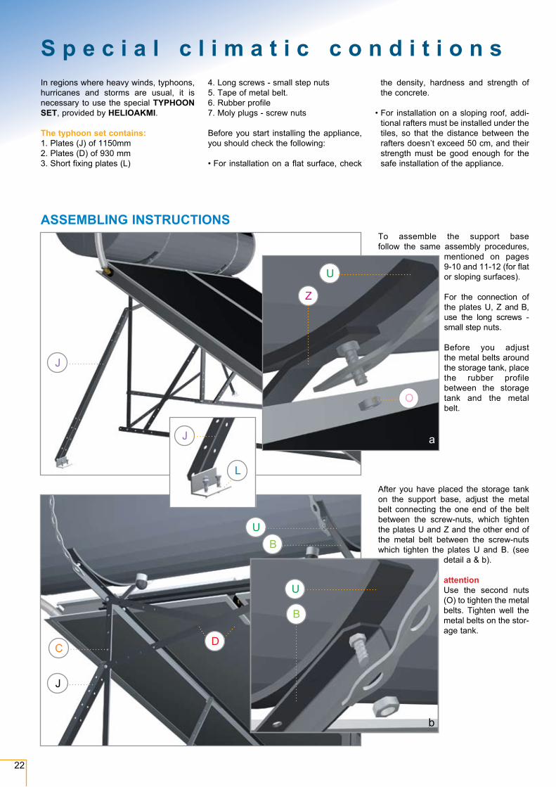
To assemble the support base follow the same assembly procedures,
mentioned on pages 9-10 and 11-12 (for flat or sloping surfaces).
For the connection of the plates U, Z and B, use the long screws - small step nuts.
Before you adjust the metal belts around the storage tank, place the rubber profile between the storage tank and the metal belt.
After you have placed the storage tank on the support base, adjust the metal belt connecting the one end of the belt between the screw-nuts, which tighten the plates U and Z and the other end of the metal belt between the screw-nuts which tighten the plates U and B. (see
detail a & b).
attentionUse the second nuts (O) to tighten the metal belts. Tighten well the metal belts on the stor-age tank.
ASSEMBLING INSTRUCTIONS
J
UB
J
C D
b
U
B
J
L
a
U
Z
O
23
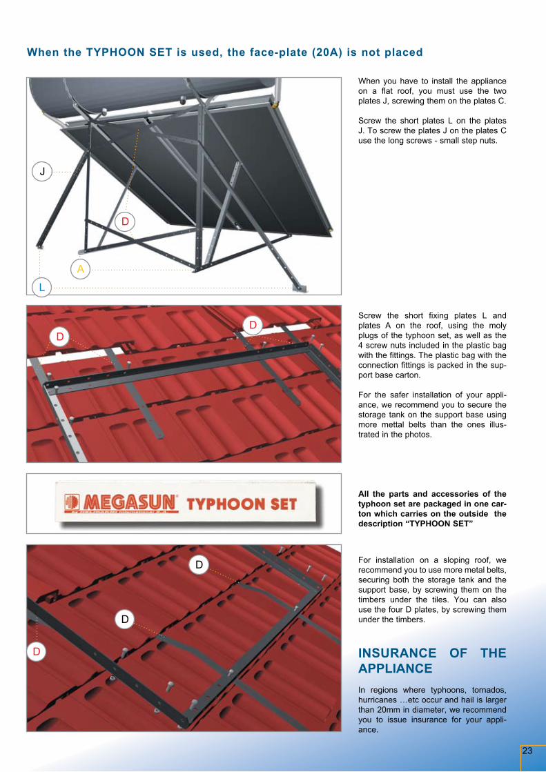
When you have to install the appliance on a flat roof, you must use the two plates J, screwing them on the plates C.
Screw the short plates L on the plates J. To screw the plates J on the plates C use the long screws - small step nuts.
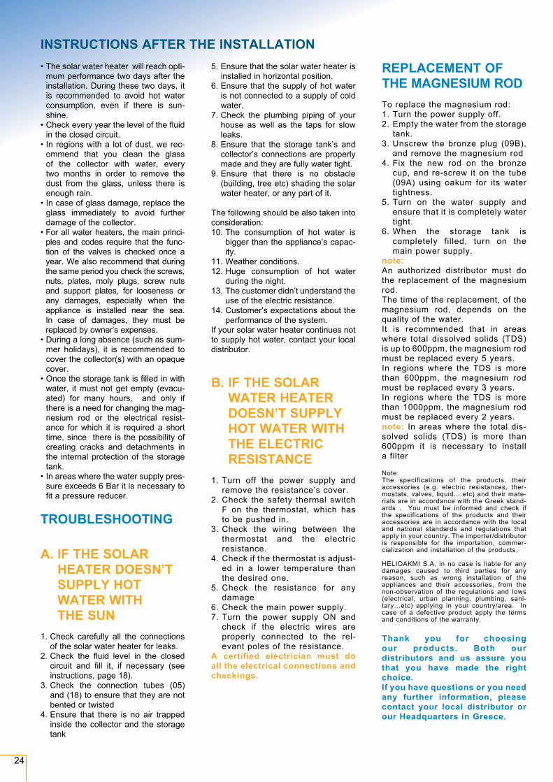
Screw the short fixing plates L and plates A on the roof, using the moly plugs of the typhoon set, as well as the 4 screw nuts included in the plastic bag with the fittings. The plastic bag with the connection fittings is packed in the sup-port base carton.
For the safer installation of your appli-ance, we recommend you to secure the storage tank on the support base using more mettal belts than the ones illus-trated in the photos.
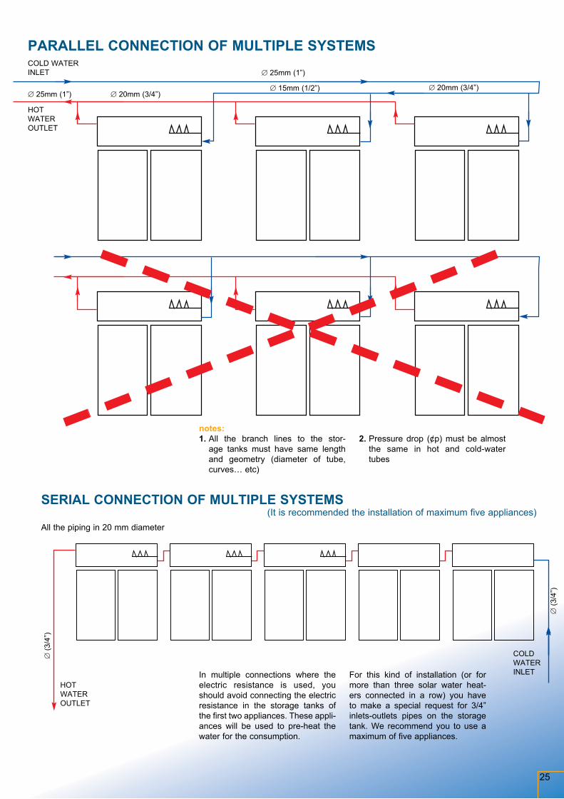
All the parts and accessories of the typhoon set are packaged in one car-ton which carries on the outside the description “TYPHOON SET”
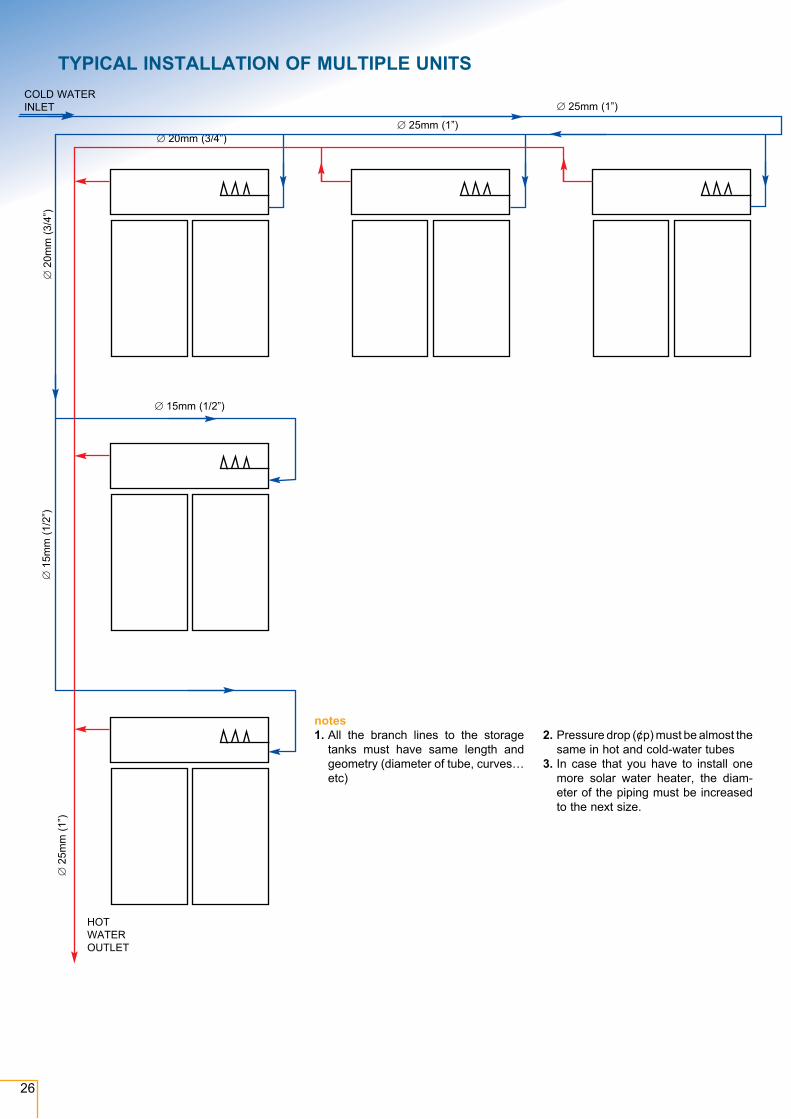
For installation on a sloping roof, we recommend you to use more metal belts, securing both the storage tank and the support base, by screwing them on the timbers under the tiles. You can also use the four D plates, by screwing them under the timbers.
INSURANCE OF THE APPLIANCEIn regions where typhoons, tornados, hurricanes …etc occur and hail is larger than 20mm in diameter, we recommend you to issue insurance for your appli-ance.
When the TYPHOON SET is used, the face-plate (20A) is not placed
J
L
A
DD
b
U
B
J
L
a
U
Z
O
D
D
D
D
24
• The solar water heater will reach opti-mum performance two days after the installation. During these two days, it is recommended to avoid hot water consumption, even if there is sun-shine.
• Check every year the level of the fluid in the closed circuit.
• In regions with a lot of dust, we rec-ommend that you clean the glass of the collector with water, every two months in order to remove the dust from the glass, unless there is enough rain.
• In case of glass damage, replace the glass immediately to avoid further damage of the collector.
• For all water heaters, the main princi-ples and codes require that the func-tion of the valves is checked once a year. We also recommend that during the same period you check the screws, nuts, plates, moly plugs, screw nuts and support plates, for looseness or any damages, especially when the appliance is installed near the sea. In case of damages, they must be replaced by owner’s expenses.
• During a long absence (such as sum-mer holidays), it is recommended to cover the collector(s) with an opaque cover.
• Once the storage tank is filled in with water, it must not get empty (evacu-ated) for many hours, and only if there is a need for changing the mag-nesium rod or the electrical resist-ance for which it is required a short time, since there is the possibility of creating cracks and detachments in the internal protection of the storage tank.
• In areas where the water supply pres-sure exceeds 6 Bar it is necessary to fit a pressure reducer.
TROUBLESHOOTING
A. IF THE SOLAR HEATER DOESN’T SUPPLY HOT WATER WITH THE SUN
1. Check carefully all the connections
of the solar water heater for leaks.2. Check the fluid level in the closed
circuit and fill it, if necessary (see instructions, page 18).
3. Check the connection tubes (05) and (18) to ensure that they are not bented or twisted
4. Ensure that there is no air trapped inside the collector and the storage tank
5. Ensure that the solar water heater is installed in horizontal position.
6. Ensure that the supply of hot water is not connected to a supply of cold water.
7. Check the plumbing piping of your house as well as the taps for slow leaks.
8. Ensure that the storage tank’s and collector’s connections are properly made and they are fully water tight.
9. Ensure that there is no obstacle (building, tree etc) shading the solar water heater, or any part of it.
The following should be also taken into consideration:10. The consumption of hot water is
bigger than the appliance’s capac-ity.
11. Weather conditions.12. Huge consumption of hot water
during the night.13. The customer didn’t understand the
use of the electric resistance.14. Customer’s expectations about the
performance of the system.If your solar water heater continues not to supply hot water, contact your local distributor.
B. IF THE SOLAR WATER HEATER DOESN’T SUPPLY HOT WATER WITH THE ELECTRIC RESISTANCE
1. Turn off the power supply and remove the resistance’s cover.
2. Check the safety thermal switch F on the thermostat, which has to be pushed in.
3. Check the wiring between the thermostat and the electric resistance.
4. Check if the thermostat is adjust-ed in a lower temperature than the desired one.
5. Check the resistance for any damage
6. Check the main power supply.7. Turn the power supply ON and
check if the electric wires are properly connected to the rel-evant poles of the resistance.
A certified electrician must do all the electrical connections and checkings.
REPLACEMENT OF THE MAGNESIUM ROD
To replace the magnesium rod:1. Turn the power supply off.2. Empty the water from the storage
tank.3. Unscrew the bronze plug (09B),
and remove the magnesium rod4. Fix the new rod on the bronze
cup, and re-screw it on the tube (09A) using oakum for its water tightness.
5. Turn on the water supply and ensure that it is completely water tight.
6. When the storage tank is completely filled, turn on the main power supply.
note: An authorized distributor must do the replacement of the magnesium rod.The time of the replacement, of the magnesium rod, depends on the quality of the water. It is recommended that in areas where total dissolved solids (TDS) is up to 600ppm, the magnesium rod must be replaced every 5 years. In regions where the TDS is more than 600ppm, the magnesium rod must be replaced every 3 years. In regions where the TDS is more than 1000ppm, the magnesium rod must be replaced every 2 years. note: In areas where the total dis-solved solids (TDS) is more than 600ppm it is necessary to install a filter
Note:The specifications of the products, their accessories (e.g. electric resistances, ther-mostats, valves, liquid….etc) and their mate-rials are in accordance with the Greek stand-ards . You must be informed and check if the specifications of the products and their accessories are in accordance with the local and national standards and regulations that apply in your country. The importer/distributor is responsible for the importation, commer-cialization and installation of the products.
HELIOAKMI S.A. in no case is liable for any damages caused to third parties for any reason, such as wrong installation of the appliances and their accessories, from the non-observation of the regulations and lows (electrical, urban planning, plumbing, sani-tary…etc) applying in your country/area. In case of a defective product apply the terms and conditions of the warranty.
Thank you for choosing our products. Both our distributors and us assure you that you have made the right choice.If you have questions or you need any further information, please contact your local distributor or our Head quarters in Greece.
INSTRUCTIONS AFTER THE INSTALLATION
25
PARALLEL CONNECTION OF MULTIPLE SYSTEMS
notes: 1. All the branch lines to the stor-
age tanks must have same length and geometry (diameter of tube, curves… etc)
2. Pressure drop (¢p) must be almost the same in hot and cold-water tubes
∅ 20mm (3/4”)∅ 15mm (1/2”) ∅ 20mm (3/4”)
∅ 25mm (1”)
∅ 25mm (1”)
COLD WATER INLET
HOT WATER OUTLET
SERIAL CONNECTION OF MULTIPLE SYSTEMS (It is recommended the installation of maximum five appliances)
In multiple connections where the electric resistance is used, you should avoid connecting the electric resistance in the storage tanks of the first two appliances. These appli-ances will be used to pre-heat the water for the consumption.
For this kind of installation (or for more than three solar water heat-ers connected in a row) you have to make a special request for 3/4” inlets-outlets pipes on the storage tank. We recommend you to use a maximum of five appliances.
All the piping in 20 mm diameter
COLD WATER INLET
HOT WATER OUTLET
∅ (3
/4”)
∅ (3
/4”)
26
TYPICAL INSTALLATION OF MULTIPLE UNITS
notes 1. All the branch lines to the storage
tanks must have same length and geo metry (diameter of tube, curves… etc)
2. Pressure drop (¢p) must be almost the same in hot and cold-water tubes
3. In case that you have to install one more solar water heater, the diam-eter of the piping must be increased to the next size.
COLD WATER INLET ∅ 25mm (1”)
∅ 25mm (1”)∅ 20mm (3/4”)
∅ 2
0mm
(3/4
”)∅
15m
m (1
/2”)
∅ 15mm (1/2”)
∅ 2
5mm
(1”)
HOT WATER OUTLET
27
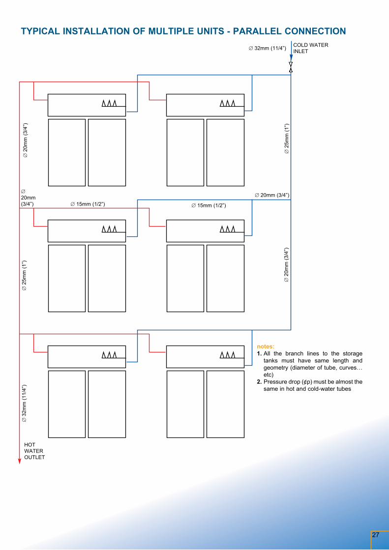
TYPICAL INSTALLATION OF MULTIPLE UNITS - PARALLEL CONNECTION
notes: 1. All the branch lines to the storage
tanks must have same length and geo metry (diameter of tube, curves… etc)
2. Pressure drop (¢p) must be almost the same in hot and cold-water tubes
COLD WATERINLET∅ 32mm (11/4”)
∅ 2
5mm
(1”)
∅ 20mm (3/4”)∅ 20mm (3/4”)
∅ 2
0mm
(3/4
”)
∅ 15mm (1/2”)∅ 15mm (1/2”)
∅ 2
0mm
(3/4
”)∅
25m
m (1
”)∅
32m
m (1
1/4”
)
HOT WATER OUTLET
28
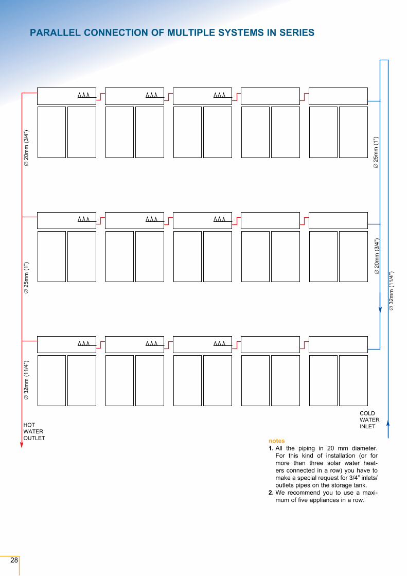
PARALLEL CONNECTION OF MULTIPLE SYSTEMS IN SERIES
notes1. All the piping in 20 mm diameter.
For this kind of installation (or for more than three solar water heat-ers connected in a row) you have to make a special request for 3/4” inlets/outlets pipes on the storage tank.
2. We recommend you to use a maxi-mum of five appliances in a row.
COLD WATER INLET
∅ 3
2mm
(11/
4”)
∅ 3
2mm
(11/
4”)
∅ 2
5mm
(1”)
∅ 2
5mm
(1”)
∅ 2
0mm
(3/4
”)
∅ 2
0mm
(3/4
”)
HOT WATER OUTLET
29
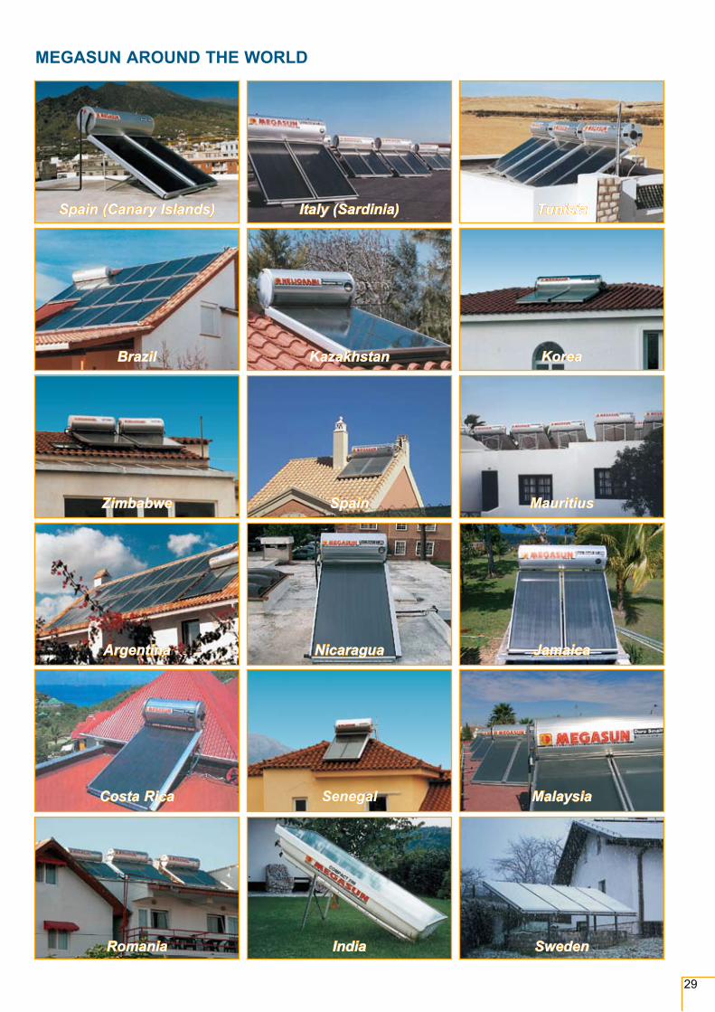
MEGASUN AROUND THE WORLD
Spain (Canary Islands) Italy (Sardinia) Tunisia
Brazil Kazakhstan Korea
Zimbabwe Spain Mauritius
Argentina Nicaragua Jamaica
Romania India Sweden
Costa Rica Senegal Malaysia
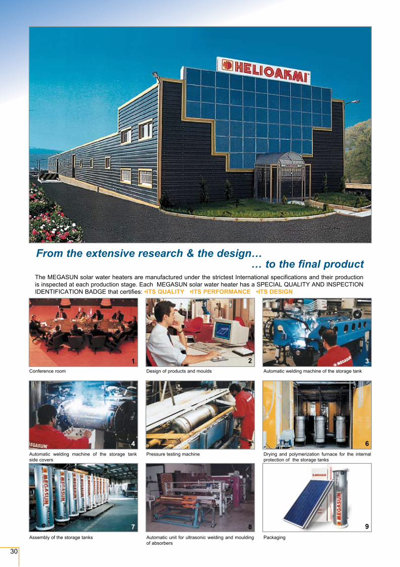
Conference room
Automatic welding machine of the storage tank side covers
Assembly of the storage tanks
Design of products and moulds
Pressure testing machine
Automatic unit for ultrasonic welding and moulding of absorbers
Automatic welding machine of the storage tank
Drying and polymerization furnace for the internal protection of the storage tanks
Packaging
1 2 3
4 5 6
7 8 9
30
From the extensive research & the design…… to the final product
The MEGASUN solar water heaters are manufactured under the strictest International specifications and their production is inspected at each production stage. Each MEGASUN solar water heater has a SPECIAL QUALITY AND INSPECTION IDENTIFICATION BADGE that certifies: •ITS QUALITY •ITS PERFORMANCE •ITS DESIGN
31
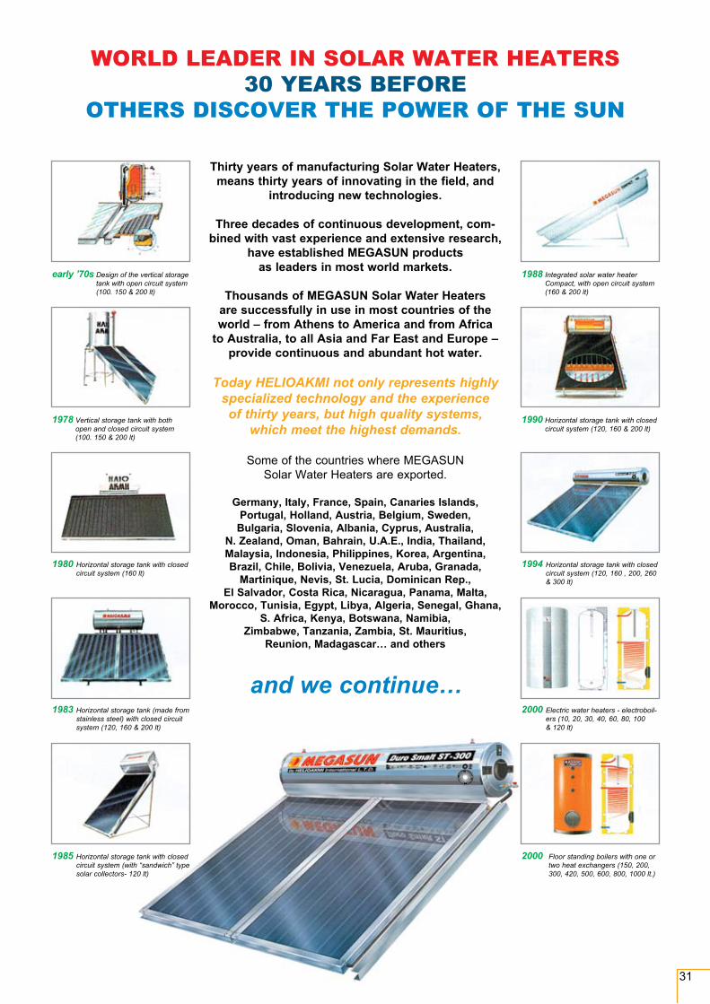
early ’70s Design of the vertical storage tank with open circuit system (100. 150 & 200 lt)
1978 Vertical storage tank with both open and closed circuit system (100. 150 & 200 lt)
1980 Horizontal storage tank with closed circuit system (160 lt)
1983 Horizontal storage tank (made from stainless steel) with closed circuit system (120, 160 & 200 lt)
1985 Horizontal storage tank with closed circuit system (with “sandwich” type solar collectors- 120 lt)
1988 Integrated solar water heater Compact, with open circuit system (160 & 200 lt)
1990 Horizontal storage tank with closed circuit system (120, 160 & 200 lt)
1994 Horizontal storage tank with closed circuit system (120, 160 , 200, 260 & 300 lt)
2000 Electric water heaters - electroboil-ers (10, 20, 30, 40, 60, 80, 100 & 120 lt)
Thirty years of manufacturing Solar Water Heaters, means thirty years of innovating in the field, and
introducing new technologies.
Three decades of continuous development, com-bined with vast experience and extensive research,
have established MEGASUN products as leaders in most world markets.
Thousands of MEGASUN Solar Water Heaters are successfully in use in most countries of the world – from Athens to America and from Africa
to Australia, to all Asia and Far East and Europe – provide continuous and abundant hot water.
Today HelIoAKMI not only represents highly specialized technology and the experience of thirty years, but high quality systems,
which meet the highest demands.
Some of the countries where MEGASUN Solar Water Heaters are exported.
Germany, Italy, France, Spain, Canaries Islands, Portugal, Holland, Austria, Belgium, Sweden,
Bulgaria, Slovenia, Albania, Cyprus, Australia, N. Zealand, Oman, Bahrain, U.A.E., India, Thailand, Malaysia, Indonesia, Philippines, Korea, Argentina, Brazil, Chile, Bolivia, Venezuela, Aruba, Granada,
Martinique, Nevis, St. Lucia, Dominican Rep., El Salvador, Costa Rica, Nicaragua, Panama, Malta,
Morocco, Tunisia, Egypt, Libya, Algeria, Senegal, Ghana, S. Africa, Kenya, Botswana, Namibia,
Zimbabwe, Tanzania, Zambia, St. Mauritius, Reunion, Madagascar… and others
WORLD LEADER IN SOLAR WATER HEATERS30 YEARS BEFORE
OTHERS DISCOVER THE POWER OF THE SUN
and we continue…
2000 Floor standing boilers with one or two heat exchangers (150, 200, 300, 420, 500, 600, 800, 1000 lt.)
Helioakmi S.A., Nea Zoi, 19300, ASPROPYRGOS, ATTIKI, GREECE Tel.: (+30) 210 5595 624 - 210 5595 625 - 210 5595 626, Fax: (+30) 210 5595723 web-site: www.helioakmi.com • e-mail: [email protected]
ISO 9001 QUALITY SYSTEMISO 9001 QUALITY SYSTEMG
raph
ic A
rtist
: Des
pina
Sam
ourk
asog
lou,
226
70 2
9305
, 699
7 03
3996
, dsa
m@
omni
net.g
r • 3
D: O
Mn
InE
T, 2
10 9
5 36
360
, om
nine
t@om
nine
t.gr
Cov
er p
hoto
: Ale
xis
Sof
iano
poul
os, +
30 2
10 8
1422
59, m
ob.:
6932
200
0768
, ww
w. f
otog
rafe
i.gr,
e-m
ail:
aale
x@ot
enet
.gr
Distributor:
NOTE: HELIOAKMI S.A reserves the right to change any specifications of the product and their accessories without prior notice.
INTERNATIONAL RECOGNITION
INTERNATIONAL RECOGNITION
090210

![Инструкция2 - geolex-geolex.rugeolex-geolex.ru/media/docs/MegaSun_Tower_V_Manual.pdf · no megaSun . uri npMKpenHTe nocraaneHHyo npenynpeAvtTenbHyk] acne aarapa, npoaonxaeT](https://img.pdfslide.net/doc/110x75/5ac0667e7f8b9ad73f8baf8b/2-geolex-megasun-uri-npmkpenhte-nocraanehhyo-npenynpeavttenbhyk.jpg)