Embed Size (px)
Citation preview
Atlanta Attachment Company
362 Industrial Park Drive
Lawrenceville, GA 30046
770-963-7369 • www.atlatt.com
Technical Manual & Parts Lists
Model 1384 Revision 3.7 Updated Jan 27, 2016


Technical Manual & Parts Lists
ATLANTA ATTACHMENT COMPANY, INC.
Confidential and Proprietary Information The materials contained herein are confidential and proprietary information of Atlanta Attachment Company. In addition to any confidentiality and non-disclosure obligations that currently exist between you and Atlanta Attachment Company, your use of these materials serves as an acknowledgment of the confidential and proprietary nature of these materials and your duty not to make any unauthorized use or disclosure of these materials. All materials contained herein are additionally protected by United States Copyright law and may not be used, disclosed, reproduced, distributed, published or sold without the express written consent of Atlanta Attachment Company, which consent may be withheld in Atlanta Attachment Company’s sole discretion. You may not alter or remove any copyright, trademark or other notice from copies of these materials.
IMPORTANTIt is important to read and understand the information contained within this manual before attempting to operate the machine. Atlanta Attachment Co., Inc. shall not be held liable for damage resulting from misuse of the information presented within, and reserves the right to change the information contained within, without prior notification.

Technical Manual & Parts Lists
Contents Important Safety Instruction ....................................................................................................................... 1
Liability ...................................................................................................................................................... 2
Safety Equipment on the Machines ............................................................................................................ 3
Protective Eyewear ..................................................................................................................................... 4
Important Notices........................................................................................................................................ 5
Maintenance ................................................................................................................................................ 7
Repair .......................................................................................................................................................... 8
A Word to the End User.............................................................................................................................. 9
Safety Precautions ....................................................................................................................................... 9
General Description .................................................................................................................................. 10
Blade Canister Installation ........................................................................................................................ 11
Machine Operation.................................................................................................................................... 12
Remove Cut Roll and Load....................................................................................................................... 13
Stiff Arms Adjustment and Use (optional) ............................................................................................... 13
Retainer Plates (optional) .......................................................................................................................... 13
Changing Blade ......................................................................................................................................... 14
Bow Alignment ......................................................................................................................................... 15
Gearbox Lubrication ................................................................................................................................. 15
Programming the Distance on Roll Slitter ................................................................................................ 16
Preventative Maintenance ......................................................................................................................... 17
Troubleshooting ........................................................................................................................................ 18
Crane Installation (optional) ..................................................................................................................... 18
Assembly Drawings & Parts Lists ............................................................................................................ 21
1384-Kit2 Shrink Wrap Mount ................................................................................................................. 22
Dovetail ..................................................................................................................................................... 23
Control Handle .......................................................................................................................................... 25
Bow ........................................................................................................................................................... 26
Hinge Pin .................................................................................................................................................. 27
Motor & Collet .......................................................................................................................................... 28
Traverse Block- 4” .................................................................................................................................... 29
1” Tensioner Head (1384-034 assembly) ............................................................................................... 30
Stiff Arms.................................................................................................................................................. 31
Air Spring or Gas Spring (all Models 1384-033) ..................................................................................... 32

Technical Manual & Parts Lists
1
Important Safety Instruction This part of the Instruction Material is provided for the safe use of your equipment. It contains important information to help work safely with the unit and describes the dangers inherent in machinery. Some of these dangers are obvious, while others are less evident.
Mandatory Information
All persons operating and/or working on the 1384should read and understand all parts of the Safety Instructions. This applies, in particular, for persons who only operate and/or work on the unit occasionally (e.g. for maintenance and repair). Persons who have difficulty reading must receive particularly thorough instruction.
Scope of the Instruction Material
The Instruction Material comprises: Safety information Operator Instructions Electrical and Pneumatic diagrams
And may also include; A list of recommended spare parts Instruction Manual(s) for components made by other manufacturers The layout and installation diagram containing information for installation
Intended Use
Our machines are designed and built in line with the state of the art and the accepted safety rules. However, all machines may endanger the life and limb of their users and/or third parties and be damaged or cause damage to other property, particularly if they are operated incorrectly or used for purposes other than those specified in the Instruction Manual.
Exclusion of Misuse
Non-conforming uses include, for example, using the equipment for something other than it was designed for, as well as operation without duly installed safety equipment. The risk rests exclusively with the end user. Conforming use of the machine includes compliance with the technical data, information and regulations in all parts of the complete Instruction Material, as well as compliance with the maintenance regulations. All local safety and accident prevention regulations must also be observed.

Technical Manual & Parts Lists
2
Liability
The machine should only be operated when in perfect working order, with due regard for safety and the potential dangers, as well as in accordance with the Instruction Material. Faults and malfunctions capable of impairing safety should be remedied immediately. We cannot accept any liability for personal injury or property damage due to operator errors or non-compliance with the safety instructions contained in this booklet. The risk rests exclusively with the end user. The Instruction Material should always be kept near the machine so that it is accessible to all concerned. The local, general, statutory and other binding regulations on accident prevention and environmental protection must also be observed in addition to the Instruction Material. The operating staff must be instructed accordingly. This obligation also includes the handling of dangerous substances and provision/use of personal protective equipment. The Instruction Material should be supplemented by instructions, including supervisory and notification duties with due regard for special operational features, such as the organization of work, work sequences, the personnel deployed, etc. The personnel's awareness of the dangers and compliance with the safety regulations should be checked at irregular intervals.
Choice and Qualification of Personnel
Ensure that work on the machine is only carried out by reliable persons who have been appropriately trained for such work - either within the company, by our field staff or at our office - and who have not only been duly appointed and authorized, but are also fully familiar with the local regulations. Work on the machine should only be carried out by skilled personnel, under the management and supervision of a duly qualified engineer. This not only applies when the machine is used for production, but also for special work associated with its operation (start-up and maintenance), especially when it concerns work on the hydraulic or electrical systems, as well as on the software/serial bus system.
Training
Everyone working on or with the machine should be duly trained and informed with regard to correct use of the safety equipment, the foreseeable dangers which may arise during operation of the machine and the safety precautions to be taken. In addition, the personnel should be instructed to check all safety mechanisms at regular intervals.
Responsibilities
Clearly define exactly who is responsible for operating, setting-up, servicing and repairing the machine. Define the responsibilities of the machine operator and authorize him to refuse any instructions by third parties if they run contrary to the machine's safety. This applies in particular for the operators of machines linked to other equipment. Persons receiving training of any kind may only work on or with the machine under the constant supervision of an experienced operator. Note the minimum age limits permitted by law.

Technical Manual & Parts Lists
3
A Word to the Operator
The greatest danger inherent in our machines: is that of fingers, hands or loose clothing being drawn into a machine by live, coasting or rotating tools or assemblies or of being cut by sharp tools or burned by hot elements. ALWAYS BE CONSCIOUS OF THESE DANGERS!
Safety Equipment on the Machines
All machines are delivered with safety equipment, which shall not be removed or bypassed during operation. The correct functioning of safety equipment on machines and systems should be checked every day and before every new shift starts, after maintenance and repair work, when starting up for the first time and when restarting (e.g. after prolonged shutdowns).
If safety equipment has to be dismantled for setting-up, maintenance or repair work, such safety equipment shall be replaced and checked immediately upon completing the maintenance or repair work. All protective mechanisms shall be fitted and fully operational whenever the machine is at a standstill or if it has been shut down for a longer period of time.
Damage
If any changes capable of impairing safety are observed in the machine or its mode of operation, such as malfunctions, faults or changes in the machine or tools, appropriate steps must be taken immediately, the machine switched off and a proper lockout tagout procedure followed. The machine should be examined for obvious damage and defects at least once per shift. Damage found shall be immediately remedied by a duly authorized person before resuming operation of machine. The machine should only be operated when in perfect working order and when all protective mechanisms and safety equipment, such as detachable protective mechanisms, emergency STOP systems, etc. are in place and operational.
Faults or Errors
The machine must be switched off and all moving or rotating parts allowed to come to a standstill and secured against accidental restart before starting to remedy any faults or errors.
Signs on the Machine
Safety and danger signs on the machine should be observed and checked at regular intervals to ensure that they are complete and undamaged. They should be clearly visible and legible at all times. Clothing, Jewelry, Protective Equipment Long loose hair, loose-fitting clothes, gloves and jewelry, including rings, should be avoided in order to avoid injuries due to being caught, drawn in and wound up inside the machine.
Technical Manual & Parts Lists
4
Protective Eyewear Protective eyewear that has been tested by the local authorities should be worn whenever there is a possibility of loose or flying objects or particles such as when cleaning the machine with compressed air.
Tools
Always count the number of tools in your possession before starting work on the machine. This will allow you to check that no tools have been left behind inside the machine. Never leave a tool in the machine while working.
Oils, Lubricants, Chemicals
Note the applicable safety regulations for the product used.
No Smoking, Fire, Explosion Hazard
Smoking and open flame (e.g. welding work) should be prohibited in the production area due to the risk of fire and explosions.
Workplace
A clear working area without any obstructions whatsoever is essential for safe operation of the machine. The floor should be level and clean, without any waste. The workplace should be well lit, either by the general lighting or by local lights.
Emergency STOP
The emergency STOP buttons bring all machine movements to a standstill. Make sure you know exactly where they are located and how they work. Try them out. Always ensure easy access to the nearest emergency STOP button while working on the machine.
First Aid
1. Keep calm even when injured. 2. Clear the operator from the danger zone. The decision of what to do and whether to seek
additional assistance rests entirely with you, particularly if someone has been trapped. 3. Give First Aid. Special courses are offered by such organizations as the employers' liability
insurance association. Your colleagues should be able to rely on you and vice versa. 4. Call an ambulance. Do you know the telephone numbers for the ambulance service, police and
fire service?

Technical Manual & Parts Lists
5
Important Notices
Reporting and Fighting Fires
Read the instructions posted in the factory with regard to reporting fires and the emergency exits. Make sure you know exactly where the fire extinguishers and sprinkler systems are located and how they are operated. Pass on the corresponding information to the firemen when they arrive. Ensure there are enough signs to avoid fire hazards. The following fire extinguishers may be used: - Dry powder extinguishers, ABC fire-extinguishing powder. - Carbon dioxide fire extinguishers to DIN 14461 for electronic components. Great care must be exercised when using carbon dioxide fire extinguishers in confined, badly ventilated rooms (see DIN 14406 and 14270). Isolate the machine from the power supply if a fire breaks out. Do not use water on burning electrical parts until it is absolutely certain that they have been completely disconnected from the power supply. Burning oils, lubricants, plastics and coatings on the machine can give off gases and vapors that may be harmful to your health. A qualified person should be consulted to repair the damage after a fire.
Electrical Power Supply
Before undertaking any maintenance or repair work on the machine, switch off the electrical power to the machine at the main source and secure it with a padlock so that it cannot be switched on again without authorization. In practice, this may mean that the technician, electrician and operator all attach their own padlock to the master switch simultaneously so that they can carry out their work safely. Locking extension plates should be available for multiple locks if required. The primary purpose for a lockout/tagout procedure is to protect workers
from injury caused by unexpected energizing or start-up of equipment. Energy sources (electrical/pneumatic/hydraulic, etc.) for the equipment shall be turned off or disconnected and the switches locked or labeled with a warning tag. It is the responsibility of the employer to establish control procedures. Follow lockout/tagout procedures before, setup and/or any service or maintenance work is performed, including lubrication, cleaning or clearance of jams. Caution: The machine is still not completely de-energized even when the master switch is off. - Electricity - The machine is always isolated from the electrical power supply whenever the master switch has been switched off. However, this does not apply for the power supply in the control cabinet, nor for equipment that does not draw its power via the master switch. - Pneumatic / hydraulic energy - Almost all our machines carry compressed air. In addition to switching off the master switch, the air supply must also be disconnected and the machine checked to ensure it is depressurized before starting any work on the machine; otherwise the machine may execute uncontrolled movements.

Technical Manual & Parts Lists
6
- Kinetic energy - Note that some motors or spindles, for example, may continue to run or coast run on after being switched off. - Potential energy - Individual assemblies may need to be secured if necessary for repair work.
Delivery of the Machine/Packaging
Note any markings on the packaging, such as weights, lifting points and special information. Avoid temperature fluctuations. Condensation may damage the machine.
Transport Damage
The packaging and machine must immediately be examined for signs of damage in transit. Such damage must be reported to the shipper/transporter within the applicable time limits. Contact Atlanta Attachment Company and/or your transport insurer immediately, if signs of damage are visible. Never operate a damaged machine.
Interim Storage
If the machine has to be stored temporarily, it must be oiled or greased and stored in a dry place where it is protected from the weather in order to avoid damage. A corrosion-inhibiting coating should be applied if the machine has to be stored for a longer period of time and additional precautions taken to avoid corrosion.
Transporting the Machine
Disconnect the machine from all external connections and secure any loose assemblies or parts. Never step under a suspended load. When transporting the machine or assemblies in a crate, ensure that the ropes or arms of a forklift truck are positioned as close to the edge of the crate as possible. The center of gravity is not necessarily in the middle of the crate. Note the accident prevention regulations, safety instructions and local regulations governing transport of the machine and its assemblies. Only use suitable transport vehicles, hoisting gear and load suspension devices that are in perfect working order and of adequate carrying capacity. Transport should only be entrusted to duly qualified personnel. Never allow the straps to rest against the machine enclosure and never push or pull sensitive parts of the machine. Ensure that the load is always properly secured. Before or immediately after loading the machine, secure it properly and affix corresponding warnings. All transport guards and lifting devices must be removed before the machine is started up again. Any parts that are to be removed for transport must be carefully refitted and secured before the machine is started up again.
Workplace Environment
Our machines are designed for use in enclosed rooms: Permissible ambient temperature approx. 5 - 40 °C (40 - 104 °F). Malfunctions of the control systems and uncontrolled machine movements may occur at temperatures outside this range. Protect against climatic influences, such as electrostatic charges, lightning strikes, hail, storm damage, high humidity, salinity of the air in coastal regions.

Technical Manual & Parts Lists
7
Protect against influences from the surroundings: no structure-borne vibrations, no grinding dust, or chemical vapors. Protect against unauthorized access. Ensure that the machine and accessories are set up in a stable position. Ensure easy access for operation and maintenance (Instruction Manual and layout diagram); also verify that the floor is strong enough to carry the weight of the machine.
Local Regulations
Particular attention must be paid to local and statutory regulations, etc. when installing machines and the plant (e.g. with regard to the specified escape routes). Note the safety zones in relation to adjacent machines.
Maintenance
General Safety Instructions
The machine shall be switched off, come to a standstill and be secured so that it cannot be switched on again inadvertently before starting any maintenance work whatsoever. Use proper lockout/tagout procedures to secure the machine against inadvertent startup. Remove any oil, grease, dirt and waste from the machine, particularly from the connections and screws, when starting the maintenance and/or repair work. Do not use any corrosive-cleaning agents. Use lint-free rags. Retighten all screw connections that have to be loosened for the maintenance and repair work. Any safety mechanisms that have to be dismantled for setting-up, maintenance or repair purposes must be refitted and checked immediately after completing the work.
Maintenance, Care, Adjustment
The activities and intervals specified in the Instruction Manual for carrying out adjustments, maintenance and inspections must be observed and parts replaced as specified. All hydraulic and pneumatic lines should be examined for leaks, loose connections, rubbing and damage whenever the machine is serviced. Any defects found must be remedied immediately.
Waste, Disassembly, Disposal
Waste products should be cleared from the machine as soon as possible as not to create a fire hazard. Ensure that fuels and operating lubricants, as well as replacement parts are disposed of in a safe and ecologically acceptable manner. Note the local regulations on pollution control. When scrapping (disassembling) the machine and its assemblies, ensure that these materials are disposed of safely. Either commission a specialist company familiar with the local regulations or note the local regulations when disposing of these materials yourself. Materials should be sorted properly.
Technical Manual & Parts Lists
8
Repair
Replacement Parts
We cannot accept any liability whatsoever for damage due to the use of parts made by other manufacturers or due to unqualified repair or modification of the machine.
Repair, Electrical
The power supply must be switched off (master switch off) and secured so that it cannot be switched on again inadvertently before starting any work on live parts. Those parts of the machine and plant on which inspection, maintenance or repair work is to be carried out must be isolated from the power supply, if specified. The isolated parts must first be checked to determine that they are truly de-energized before being grounded and short-circuited. Adjacent live parts must also be isolated. The protective measures implemented (e.g. grounding resistance) must be tested before restarting the machine after all assembly or repair work on electric parts. Signal generators (limit switches) and other electrical parts on the safety mechanisms must not be removed or bypassed. Only use original fuses or circuit overloads with the specified current rating. The machine must be switched off immediately if a fault develops in the electrical power supply. The electrical equipment of our machines must be checked at regular intervals and any defects found must be remedied immediately. If it is necessary to carry out work on live parts, a second person should be on hand to operate the emergency OFF switch or master switch with voltage release in the event of an emergency. The working area should be cordoned off and marked by a warning sign. Only use electrically insulated tools.
Ventilation/Hazardous Gases
It is the end users responsibility to ensure adequate ventilation is provided to exhaust any and all noxious or hazardous gases that may be present in the working environment.
Hydraulic and Pneumatic Systems
Work on hydraulic or pneumatic equipment shall only be carried out by persons with training, knowledge and experience of hydraulic systems. Pressure lines shall be depressurized before starting any repair work.
General Liability
Liability for machine damage and personal injury is extinguished completely if any unauthorized conversions or modifications are undertaken. The machine must not be modified, enlarged or converted in any way capable of affecting safety without the manufacturer's prior approval.
Starting Machine Movements
Read the Instruction Manual carefully to establish which keys and functions start machine movements.

Technical Manual & Parts Lists
9
A Word to the End User The end user has sole responsibility to enforce the use of safety procedures and guards on the machine. Any other safety devices or procedures due to local regulations should be should be retrofitted in accordance to these regulations and/or the EC Directive on the safety of machines. Operator’s position must always be readily accessible. Escape routes must always be kept clear and safety areas should be identified.
Safety Precautions Safety should be a constant concern for everyone. Always be careful when working with this equipment. While normal safety precautions were taken in the design and manufacture of this equipment, there are some potential safety hazards. Everyone involved with the operation and maintenance of this equipment should read and follow the instructions in this manual. Operate the equipment only as stated in this manual. Incorrect use could cause damage to the equipment or personal injury. It is the owner’s responsibility to make certain that the operator reads and understands this manual before operating this equipment. It is also the owner’s responsibility to make certain that the operator is a qualified and physically able individual, properly trained in the operation of this equipment. Specific safety warning decals are located on the equipment near the immediate areas of potential hazards. These decals should not be removed or obliterated. Replace them if they become non-readable.
• ALWAYS keep safety shields and covers in place, except for servicing. • ALWAYS operate equipment in daylight or with adequate working lights. • Follow daily and weekly checklists, making sure hoses are tightly secured and bolts are
tightened. • ALWAYS watch and avoid holes or deep depressions. • ALWAYS wear adequate eye protection when servicing the hydraulic system and battery. • NEVER operate a poorly maintained machine. • NEVER allow persons to operate this machine without proper instruction. • NEVER put hands or feet under any part of the machine while it is running. • NEVER attempt to make any adjustments or repairs to the machine while running. Repairs or
maintenance should be performed by trained personnel only. • NEVER work under the machine unless it is safely supported with stands, blocks or a hoist and
blocks. • NEVER touch hot parts of machine.
Technical Manual & Parts Lists
10
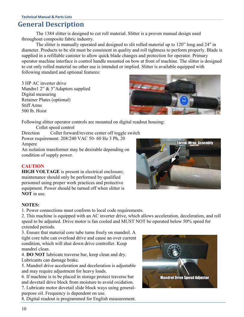
General Description The 1384 slitter is designed to cut roll material. Slitter is a proven manual design used throughout composite fabric industry. The slitter is manually operated and designed to slit rolled material up to 120” long and 24" in diameter. Products to be slit must be consistent in quality and roll tightness to perform properly. Blade is supplied in a refillable canister to allow quick blade changes and protection for operator. Primary operator machine interface is control handle mounted on bow at front of machine. The slitter is designed to cut only rolled material no other use is intended or implied. Slitter is available equipped with following standard and optional features: 3 HP AC inverter drive Mandre1 2” & 3”Adaptors supplied Digital measuring Retainer Plates (optional) Stiff Arms 500 lb. Hoist Following slitter operator controls are mounted on digital readout housing: Collet speed control Direction Collet forward/reverse center off toggle switch Power requirement: 208/240 VAC 50- 60 Hz 3 Ph, 20 Ampere An isolation transformer may be desirable depending on condition of supply power. CAUTION HIGH VOLTAGE is present in electrical enclosure; maintenance should only be performed by qualified personnel using proper work practices and protective equipment. Power should be turned off when slitter is NOT in use. NOTES: 1. Power connections must conform to local code requirements. 2. This machine is equipped with an AC inverter drive, which allows acceleration, deceleration, and roll speed to be adjusted. Drive motor is fan cooled and MUST NOT be operated below 50% speed for extended periods. 3. Ensure that material core tube turns freely on mandrel. A tight core tube can overload drive and cause an over current condition, which will shut down drive controller. Keep mandrel clean. 4. DO NOT lubricate traverse bar, keep clean and dry. Lubricants can damage brake. 5. Mandrel drive acceleration and deceleration is adjustable and may require adjustment for heavy loads. 6. If machine is to be placed in storage protect traverse bar and dovetail drive block from moisture to avoid oxidation. 7. Lubricate motor dovetail slide block ways using general-purpose oil. Frequency is dependent on use. 8. Digital readout is programmed for English measurement.
Technical Manual & Parts Lists
11
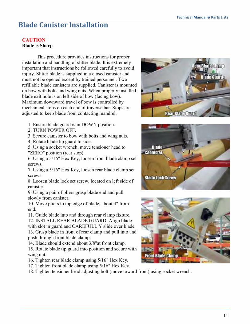
Blade Canister Installation CAUTION Blade is Sharp This procedure provides instructions for proper installation and handling of slitter blade. It is extremely important that instructions be followed carefully to avoid injury. Slitter blade is supplied in a closed canister and must not be opened except by trained personnel. Two refillable blade canisters are supplied. Canister is mounted on bow with bolts and wing nuts. When properly installed blade exit hole is on left side of bow (facing bow). Maximum downward travel of bow is controlled by mechanical stops on each end of traverse bar. Stops are adjusted to keep blade from contacting mandrel.
1. Ensure blade guard is in DOWN position. 2. TURN POWER OFF. 3. Secure canister to bow with bolts and wing nuts. 4. Rotate blade tip guard to side. 5. Using a socket wrench, move tensioner head to "ZERO" position (rear stop). 6. Using a 5/16" Hex Key, loosen front blade clamp set screws. 7. Using a 5/16" Hex Key, loosen rear blade clamp set screws. 8. Loosen blade lock set screw, located on left side of canister. 9. Using a pair of pliers grasp blade end and pull slowly from canister. 10. Move pliers to top edge of blade, about 4" from end. 11. Guide blade into and through rear clamp fixture. 12. INSTALL REAR BLADE GUARD. Align blade with slot in guard and CAREFULL Y slide over blade. 13. Grasp blade in front of rear clamp and pull into and push through front blade clamp. 14. Blade should extend about 3/8"at front clamp. 15. Rotate blade tip guard into position and secure with wing nut. 16. Tighten rear blade clamp using 5/16" Hex Key. 17. Tighten front blade clamp using 5/16" Hex Key. 18. Tighten tensioner head adjusting bolt (move toward front) using socket wrench.
Technical Manual & Parts Lists
12
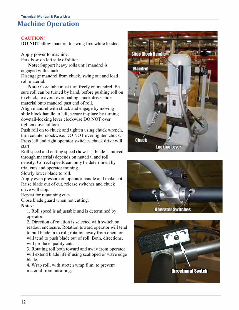
Machine Operation CAUTION! DO NOT allow mandrel to swing free while loaded Apply power to machine. Park bow on left side of slitter. Note: Support heavy rolls until mandrel is engaged with chuck. Disengage mandrel from chuck, swing out and load roll material. Note: Core tube must turn freely on mandrel. Be sure roll can be turned by hand, before pushing roll on to chuck, to avoid overloading chuck drive slide material onto mandrel past end of roll. Align mandrel with chuck and engage by moving slide block handle to left, secure in-place by turning dovetail-locking lever clockwise DO NOT over tighten dovetail lock. Push roll on to chuck and tighten using chuck wrench, turn counter clockwise. DO NOT over tighten chuck. Press left and right operator switches chuck drive will start Roll speed and cutting speed (how fast blade is moved through material) depends on material and roll density. Correct speeds can only be determined by trial cuts and operator training. Slowly lower blade to roll. Apply even pressure on operator handle and make cut. Raise blade out of cut, release switches and chuck drive will stop. Repeat for remaining cuts. Close blade guard when not cutting. Notes:
1. Roll speed is adjustable and is determined by operator. 2. Direction of rotation is selected with switch on readout enclosure. Rotation toward operator will tend to pull blade in to roll; rotation away from operator will tend to push blade out of roll. Both, directions, will produce quality cuts. 3. Rotating roll both toward and away from operator will extend blade life if using scalloped or wave edge blade. 4. Wrap roll, with stretch wrap film, to prevent material from unrolling.
Technical Manual & Parts Lists
13
Remove Cut Roll and Load CAUTION! DO NOT hammer on chuck.
1. After machine stops, close blade guard and loosen chuck using wrench, turn wrench clockwise. 2. Park bow on left side of slitter, close blade guard. 3. Push material to left off of chuck. 4. Disengage mandrel from chuck by rotating dovetail locking lever counter-clockwise, move slide block handle to right until chuck is clear of mandrel. 5. Support roll, and swing mandrel out to unload cut rolls. 6. Repeat steps 1 through 5 for next roll.
Stiff Arms Adjustment and Use (optional)
NOTES: a. Stiff arms are not required for most material, try material first. b. Stiff arms provide improved blade stability when slitting small diameter rolls. c. Stiff arms can be used to, set blade, if cut leads off when cutting, usually this is only a problem with very hard material. d. Hand tighten stiff arm blade screws, DO NOT torque Gown. 1. Place roll on mandrel. 2. Move stiff arms toward roll, do not allow still arms to contact roll. 3. Tighten blade clamp screws to just touch blade, DO NOT over tighten. 4. Make trial slits and adjust for best results.
Retainer Plates (optional)
NOTES: a. Retainer plates are used to support narrow slits and to assist in rotating loosely wound material. b. If not required remove retainer plates drive pins from machine. 1. Install retainer plate drive pins (bolt and plastic drive bushing) on chuck, ensure bolts are not bent. 2. Place right side retainer plate with drive channels on chuck. 3. Place left side retainer plate with mandrel locking ring on mandrel. 4. Load roll to be slit on mandrel. 5. Engage roll with chuck. 6. Slide left side retainer plate against roll and tighten on mandrel flat, DO NOT OVER TIGHTEN.
Technical Manual & Parts Lists
14
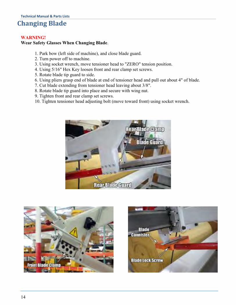
Changing Blade WARNING! Wear Safety Glasses When Changing Blade. 1. Park bow (left side of machine), and close blade guard. 2. Turn power off to machine. 3. Using socket wrench, move tensioner head to "ZERO" tension position. 4. Using 5/16" Hex Key loosen front and rear clamp set screws. 5. Rotate blade tip guard to side. 6. Using pliers grasp end of blade at end of tensioner head and pull out about 4" of blade. 7. Cut blade extending from tensioner head leaving about 3/8". 8. Rotate blade tip guard into place and secure with wing nut. 9. Tighten front and rear clamp set screws. 10. Tighten tensioner head adjusting bolt (move toward front) using socket wrench.
Technical Manual & Parts Lists
15
Bow Alignment
Proper bow alignment is necessary for satisfactory operation and should be checked on a regular schedule. Best indication of a misalignment will be poor quality cuts. CAUTION! Blade is exposed while checking alignment. 1. Turn power off 2. With no roll loaded move bow to center of mandrel. 3. Engage mandrel with chuck by moving motor slide block to left. 4. Raise blade guard. 5. Check that blade is perpendicular to machined flat on mandrel in horizontal direction. If not, shim bow as required in horizontal direction. 6. Position blade about 6" above mandrel. 7. Check that blade is perpendicular to flat on mandrel in vertical direction (tolerance I-degree toward machine chuck). 8. Loosen bow mounting bolts slightly and adjust with adjusting nut, on bottom of traverse block under bow, position bow as desired. 9. Tighten bow-mounting bolts. 10. Close blade guard.
Mandrel Changing and Adjustment NOTES: Mandrel adjustment is required when mandrel is changed to a different size. Changing mandrel is 2-person operation mandrels are heavy. 1. If mandrel is to be changed carefully lift mandrel off of hinge pin. 2. Select mandrel and place on hinge pin. 3. Adjust mandrel by loosen 2 set screws on right side of hinge pin column. 4. Adjust setscrew on left side to raise or lower mandrel. 5. Mandrel should be adjusted to allow chuck pin to slide into mandrel bearing without binding. 6. Snug up 2 set screws on right side of hinge pin column. DO NOT torque down.
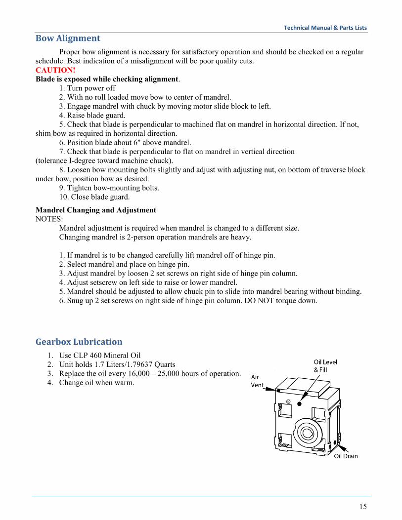
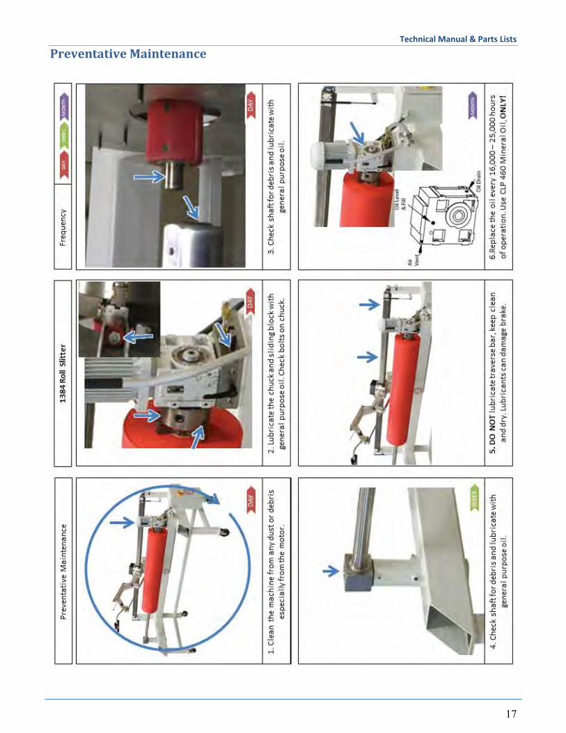
Gearbox Lubrication
1. Use CLP 460 Mineral Oil 2. Unit holds 1.7 Liters/1.79637 Quarts 3. Replace the oil every 16,000 – 25,000 hours of operation. 4. Change oil when warm.

Technical Manual & Parts Lists
16
Programming the Distance on Roll Slitter
1. First determine how far the counter is off. Place two pencil marks or tape on mandrel at 100 inches apart. Align the blade at the first mark and press the reset button. Index the blade to the second mark and make note of the display on the counter. If it is more than .1-.2 off, then you may want to adjust the scale. To adjust the scale, continue below.
2. Loosen the two set screws on the top of the enclosure that hold the counter in place and slide the counter forward out of the enclosure.
3. Temporarily disconnect the programming jumper located on the USR terminal (loosen the screw and remove the wire from USR)
4. Press and hold the SEL button to enter programming mode. The screen will flash then .
5. Press the RST button 1 time, screen will display . 6. Press the SEL button 3 times, screen will flash then
. (or some other value) 7. If your counter is measuring a number Larger than it should for
a given distance, then this value must Decrease. If your counter is measuring a number Smaller than it should for a given distance, then this value must Increase.
(Note: To give you an idea of the scale of this number, incrementing
this number by .007 will equal approximately a 1 inch change over 100 inches)
8. To adjust the value of this number, press the RST button. The rightmost digit of the number will begin flashing press the RST button again to increment this digit by 1. Continue incrementing this digit using the RST button until the desired value for this digit is reached. Use the SEL button to move to the next digit to the left and again use the RST button to increment this digit. Once all the digits have been set, press and hold the SEL button to exit the adjustment.
9. Program changes to scaling are now complete and you must exit programming by pressing the SEL multiple times (about 10x). Once you see the screen flash then , press SEL one more time and you are done and the program changes are saved.
10. Using the 100 inch marks made previously, check the adjustments that were made and adjust the scaling again if necessary.
11. Once programming is complete, re-connect the programming jumper and re-assemble the counter into the enclosure.
Technical Manual & Parts Lists
17
Preventative Maintenance
Technical Manual & Parts Lists
18
Troubleshooting
It is recommended to call a mechanic in the event the machine will not operate.
Crane Installation (optional)
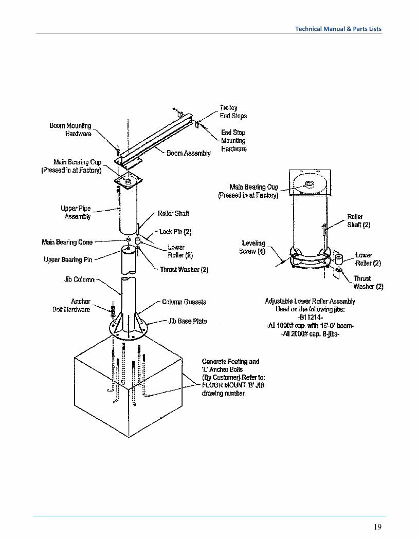
The jib crane is shipped in three sections: head assembly, mast assembly, and boom assembly. A box containing the top bearing and mounting hardware is also included. The footing shown is the only method recommended by the manufacturer. An individual competent in related foundation design methods and familiar with the installation site should design any alternative method. Use a minimum 3000 PSI (5 bag) mix for concrete. A 2500 PSF soil pressure is assumed. Prior to pouring, position the rebar and ‘L’ shaped anchor bolts as shown. Anchor bolts are submerged ¾ of footing depth. The anchor bolt material specification is A36. Rebar is located 6 inches from top and bottom of the footing. Be sure to allow for power conduit if feeding through the base of the jib. Position the anchor bolts according to the base plate bolt circle dimensions. (The anchor bolts can be purchased through your jib crane supplier.) After the concrete hardens, make sure a flat, level surface exists for accepting the mast assembly. Machinery grout and jam nuts may be used to level the surface. Erect the mast on the prepared surface, taking care not to damage the anchor bolt threads while setting the base plate in position. Tighten double nuts onto the anchor bolts after insuring that the mast is plumb. Mount the top pivot bearing cone over the pin on top of the mast assembly. If installing the bottom entry collector option; read the collector installation instructions at this time. Attach boom assembly to head assembly with the hardware provided. Set the boom and head assembly in place on the mast. Make sure the roller bearing on top of the mast is seated correctly into the bearing race on the boom assembly. Adjust the lower roller assembly in the head section to bring the boom into horizontal.* Grease upper bearing and 5” diameter lower rollers through zerk fitting provided. Re-lube as conditions require. The 3” diameter lower rollers are self-lubricating. ** Rotate the boom assembly to check for free movement and proper bearing seating. Install the trolley end stops on the boom. Attach other optional equipment according to directions provided with the equipment. *Note - Small jibs are not adjustable at the lower rollers and may be leveled by shimming between the boom and the head mounting plates. **Note - Small jibs are not equipped with a zerk fitting and need to be greased at the top bearing prior to seating the boom and head assembly.
Technical Manual & Parts Lists
19

Technical Manual & Parts Lists
20

Technical Manual & Parts Lists
21
Assembly Drawings & Parts Lists The materials contained herein are confidential and proprietary information of Atlanta Attachment Company. In addition to any confidentiality and non-disclosure obligations that currently exist between you and Atlanta Attachment Company, your use of these materials serves as an acknowledgment of the confidential and proprietary nature of these materials and your duty not to make any unauthorized use or disclosure of these materials.
Technical Manual & Parts Lists
22
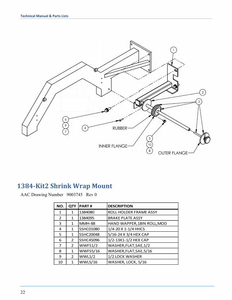
1384-Kit2 Shrink Wrap Mount AAC Drawing Number 9003745 Rev 0
NO. QTY PART # DESCRIPTION
1 1 1384080 ROLL HOLDER FRAME ASSY
2 1 1384095 BRAKE PLATE ASSY
3 1 MMH-88 HAND WAPPER,18IN ROLL,MOD
4 1 SSHC01080 1/4-20 X 1-1/4 HHCS
5 1 SSHC20048 5/16-24 X 3/4 HEX CAP
6 2 SSHC45096 1/2-13X1-1/2 HEX CAP
7 2 WWFS1/2 WASHER,FLAT,SAE,1/2
8 1 WWFS5/16 WASHER,FLAT,SAE,5/16
9 2 WWL1/2 1/2 LOCK WASHER
10 1 WWL5/16 WASHER, LOCK, 5/16
Technical Manual & Parts Lists
23
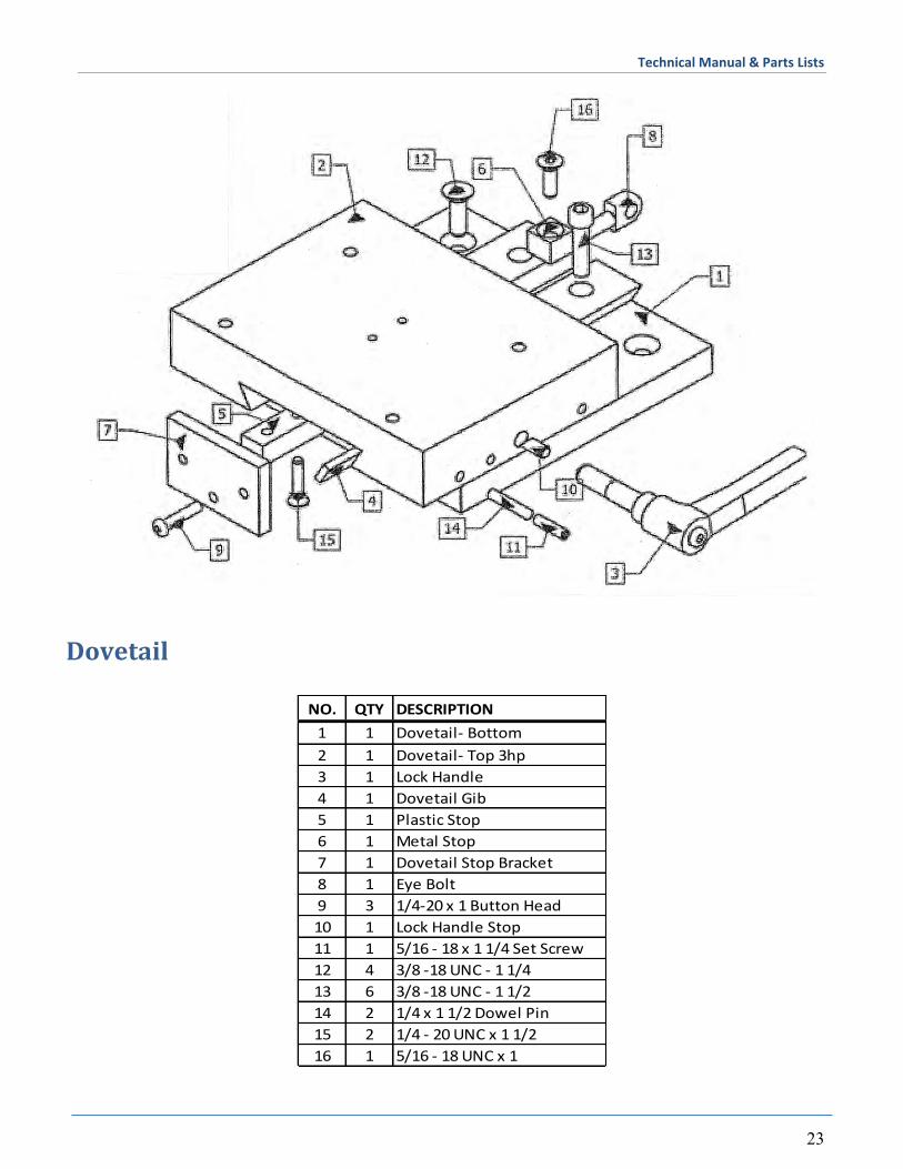
Dovetail
NO. QTY DESCRIPTION
1 1 Dovetail- Bottom
2 1 Dovetail- Top 3hp
3 1 Lock Handle
4 1 Dovetail Gib
5 1 Plastic Stop
6 1 Metal Stop
7 1 Dovetail Stop Bracket
8 1 Eye Bolt
9 3 1/4-20 x 1 Button Head
10 1 Lock Handle Stop
11 1 5/16 - 18 x 1 1/4 Set Screw
12 4 3/8 -18 UNC - 1 1/4
13 6 3/8 -18 UNC - 1 1/2
14 2 1/4 x 1 1/2 Dowel Pin
15 2 1/4 - 20 UNC x 1 1/2
16 1 5/16 - 18 UNC x 1
Technical Manual & Parts Lists
24
Technical Manual & Parts Lists
25
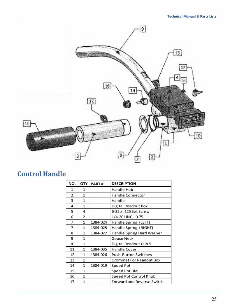
Control Handle
NO. QTY PART # DESCRIPTION
1 1 Handle Hub
2 1 Handle Connector
3 1 Handle
4 1 Digital Readout Box
5 4 6-32 x .125 Set Screw
6 2 1/4-20 UNC - 0.75
7 1 1384-024 Handle Spring (LEFT)
7 1 1384-025 Handle Spring (RIGHT)
8 1 1384-027 Handle Spring Hard Washer
9 1 Goose Neck
10 1 Digital Readout Cub 5
11 1 1384-035 Handle Cover
12 1 1384-026 Push-Button Switches
13 1 Grommet For Readout Box
14 1 1384-019 Speed Pot
15 1 Speed Pot Dial
16 1 Speed Pot Control Knob
17 1 Forward and Reverse Switch
Technical Manual & Parts Lists
26
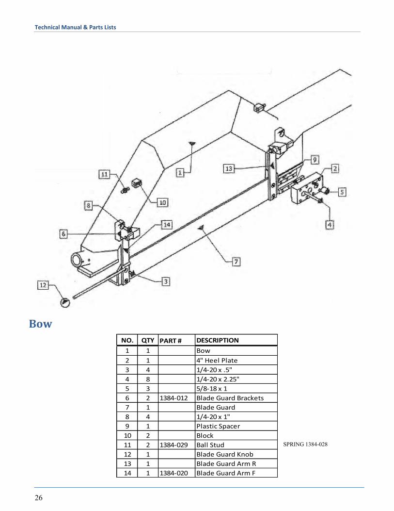
Bow
NO. QTY PART # DESCRIPTION
1 1 Bow
2 1 4" Heel Plate
3 4 1/4-20 x .5"
4 8 1/4-20 x 2.25"
5 3 5/8-18 x 1
6 2 1384-012 Blade Guard Brackets
7 1 Blade Guard
8 4 1/4-20 x 1"
9 1 Plastic Spacer
10 2 Block
11 2 1384-029 Ball Stud
12 1 Blade Guard Knob
13 1 Blade Guard Arm R
14 1 1384-020 Blade Guard Arm F
SPRING 1384-028
Technical Manual & Parts Lists
27
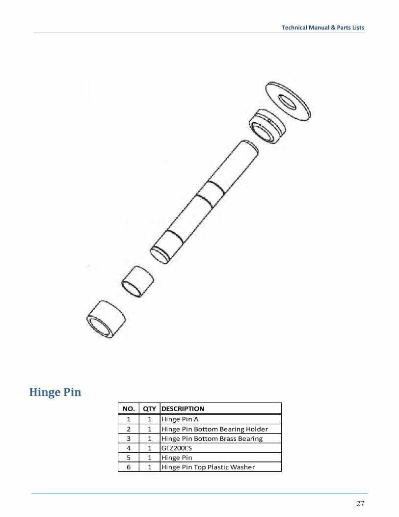
Hinge Pin
NO. QTY DESCRIPTION
1 1 Hinge Pin A
2 1 Hinge Pin Bottom Bearing Holder
3 1 Hinge Pin Bottom Brass Bearing
4 1 GEZ200ES
5 1 Hinge Pin
6 1 Hinge Pin Top Plastic Washer
Technical Manual & Parts Lists
28
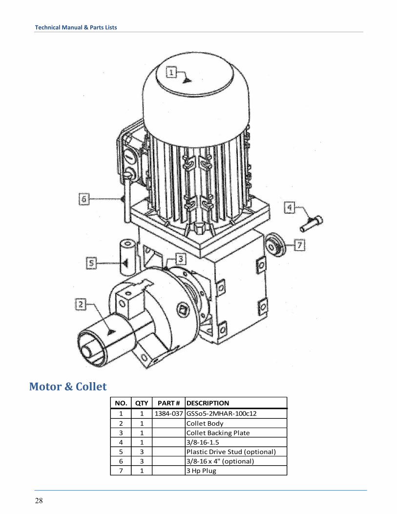
Motor & Collet
NO. QTY PART # DESCRIPTION
1 1 1384-037 GSSo5-2MHAR-100c12
2 1 Collet Body
3 1 Collet Backing Plate
4 1 3/8-16-1.5
5 3 Plastic Drive Stud (optional)
6 3 3/8-16 x 4" (optional)
7 1 3 Hp Plug
Technical Manual & Parts Lists
29
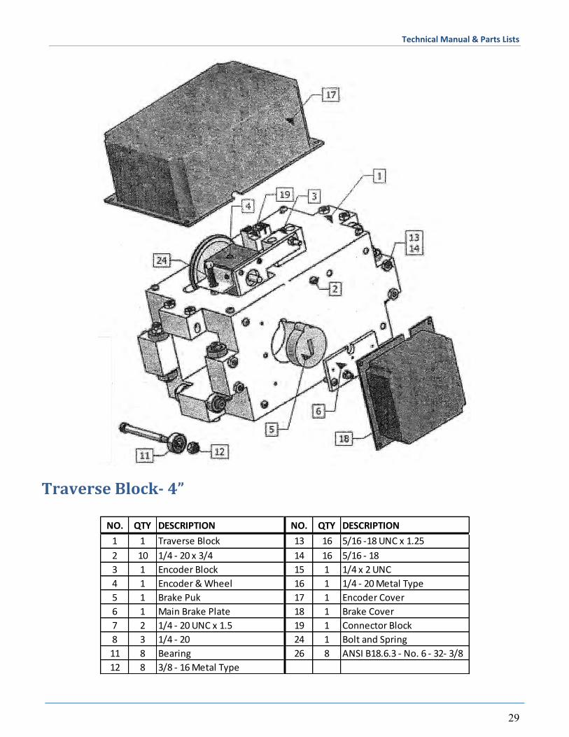
Traverse Block- 4”
NO. QTY DESCRIPTION NO. QTY DESCRIPTION
1 1 Traverse Block 13 16 5/16 -18 UNC x 1.25
2 10 1/4 - 20 x 3/4 14 16 5/16 - 18
3 1 Encoder Block 15 1 1/4 x 2 UNC
4 1 Encoder & Wheel 16 1 1/4 - 20 Metal Type
5 1 Brake Puk 17 1 Encoder Cover
6 1 Main Brake Plate 18 1 Brake Cover
7 2 1/4 - 20 UNC x 1.5 19 1 Connector Block
8 3 1/4 - 20 24 1 Bolt and Spring
11 8 Bearing 26 8 ANSI B18.6.3 - No. 6 - 32- 3/8
12 8 3/8 - 16 Metal Type
Technical Manual & Parts Lists
30
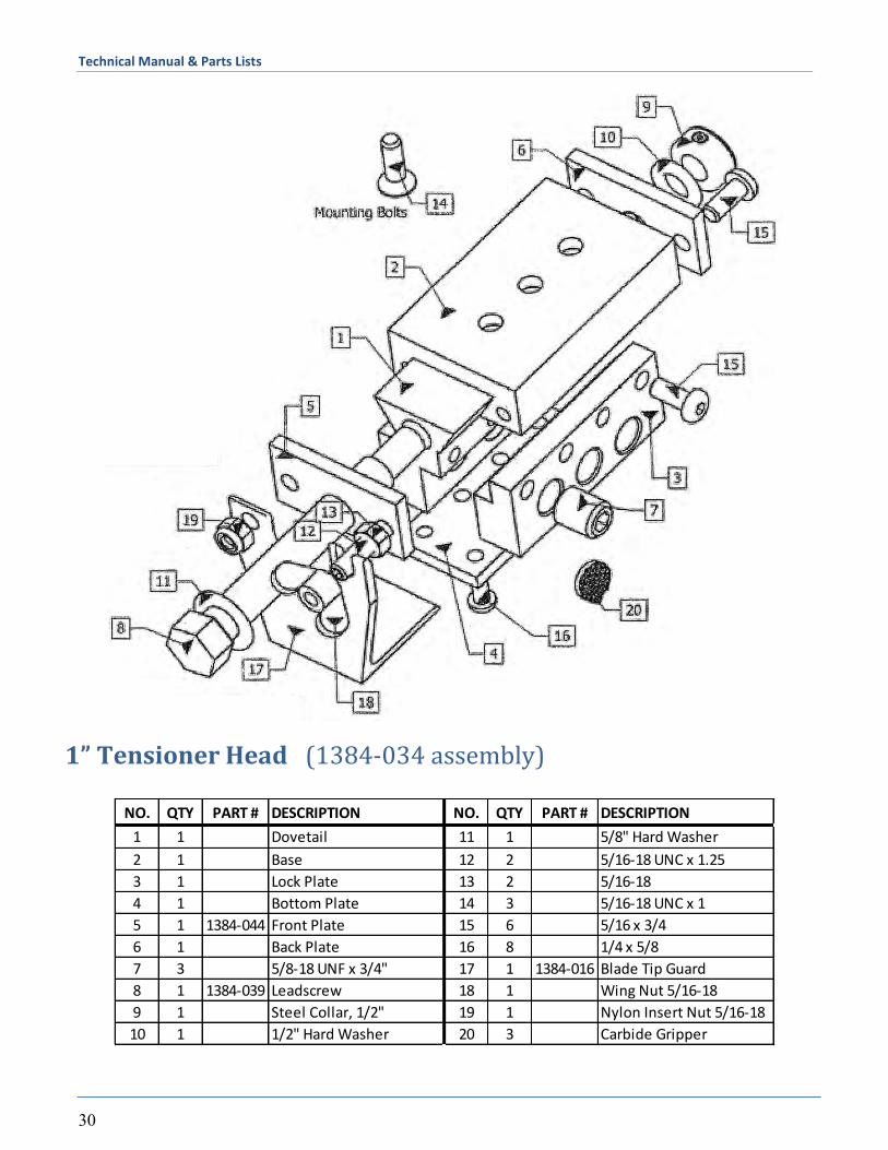
1” Tensioner Head (1384-034 assembly)
NO. QTY PART # DESCRIPTION NO. QTY PART # DESCRIPTION
1 1 Dovetail 11 1 5/8" Hard Washer
2 1 Base 12 2 5/16-18 UNC x 1.25
3 1 Lock Plate 13 2 5/16-18
4 1 Bottom Plate 14 3 5/16-18 UNC x 1
5 1 1384-044 Front Plate 15 6 5/16 x 3/4
6 1 Back Plate 16 8 1/4 x 5/8
7 3 5/8-18 UNF x 3/4" 17 1 1384-016 Blade Tip Guard
8 1 1384-039 Leadscrew 18 1 Wing Nut 5/16-18
9 1 Steel Collar, 1/2" 19 1 Nylon Insert Nut 5/16-18
10 1 1/2" Hard Washer 20 3 Carbide Gripper
Technical Manual & Parts Lists
31
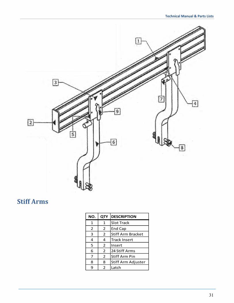
Stiff Arms
NO. QTY DESCRIPTION
1 1 Slot Track
2 2 End Cap
3 2 Stiff Arm Bracket
4 4 Track Insert
5 2 Insert
6 2 24 Stiff Arms
7 2 Stiff Arm Pin
8 8 Stiff Arm Adjuster
9 2 Latch
Technical Manual & Parts Lists
32
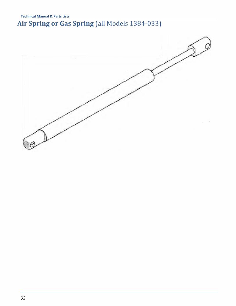
Air Spring or Gas Spring (all Models 1384-033)

Technical Manual & Parts Lists
33

Technical Manual & Parts Lists
34
Atlanta Attachment Company (AAC) Statement of Warranty
Manufactured Products Atlanta Attachment Company warrants manufactured products to be free from defects in material and workmanship for a period of eight hundred (800) hours of operation or one hundred (100) days whichever comes first. Atlanta Attachment Company warrants all electrical components of the Serial Bus System to be free from defects in material or workmanship for a period of thirty six (36) months.
Terms and Conditions: AAC Limited Warranty becomes effective on the date of shipment. AAC Warranty claims may be made by telephone, letter, fax or e-mail. All verbal claims must be con-
firmed in writing. AAC reserves the right to require the return of all claimed defective parts with a completed warranty
claim form. AAC will, at its option, repair or replace the defective machine and parts upon return to AAC. AAC reserves the right to make the final decision on all warranty coverage questions. AAC warranty periods as stated are for eight hundred (800) hours or one hundred (100) days whichever
comes first. AAC guarantees satisfactory operation of the machines on the basis of generally accepted industry
standards, contingent upon proper application, installation and maintenance. AAC Limited Warranty may not be changed or modified and is not subject to any other warranty
expressed or implied by any other agent, dealer, or distributor unless approved in writing by AAC in advance of any claim being filed.
What Is Covered Electrical components that are not included within the Serial Bus System that fail due to defects in
material or workmanship, which are manufactured by AAC are covered for a period of eight hundred (800) hours.
Mechanical parts or components that fail due to defects in material or workmanship, which are manufactured by AAC.
Purchased items (sewing heads, motors, etc.) will be covered by the manufacturers (OEM) warranty. AAC will assist in the procurement and handling of the manufacturers (OEM) claim.
What Is Not Covered Parts that fail due to improper usage, lack of proper maintenance, lubrication and/or modification. Damages caused by; improper freight handling, accidents, fire and issues resulting from unauthorized
service and/or personnel, improper electrical, plumbing connections. Normal wear of machine and parts such as Conveyor belts, "O" rings, gauge parts, cutters, needles, etc. Machine adjustments related to sewing applications and/or general machine operation. Charges for field service. Loss of time, potential revenue, and/or profits. Personal injury and/or property damage resulting from the operation of this equipment.
Technical Manual & Parts Lists
35
Declaración de Garantia
Productos Manufacturados Atlanta Attachment Company garantiza que los productos de fabricación son libres de defectos de mate-rial y de mano de obra durante un periodo de ochocientos (800) horas de operación o cien (100) días cual llegue primero. Atlanta Attachment Company garantiza que todos los componentes del Serial bus son libres de defectos de material y de mano de obra durante un periodo de treinta y seis (36) meses.
Términos y Condiciones: La Garantía Limitada de AAC entra en efecto el día de transporte. Reclamos de la Garantía de AAC pueden ser realizados por teléfono, carta, fax o correo electrónico. Todo
reclamo verbal tiene que ser confirmado vía escrito. AAC reserva el derecho para exigir el retorno de cada pieza defectuosa con un formulario de reclamo de
garantía. AAC va, según su criterio, reparar o reemplazar las máquinas o piezas defectuosas devueltas para AAC. AAC reserva el derecho para tomar la decisión final sobre toda cuestión de garantía. Las garantías de AAC tiene una validez de ochocientas (800) horas o cien (100) días cual llega prim-ero. AAC garantiza la operación satisfactoria de sus máquinas en base de las normas aceptadas de la industria
siempre y cuando se instale use y mantenga de forma apropiada. La garantía de AAC no puede ser cambiado o modificado y no está sujeto a cualquier otra garantía
implicado por otro agente o distribuidor menos al menos que sea autorizado por AAC antes de cual-quier reclamo.
Lo Que Está Garantizado Componentes eléctricos que no están incluidos dentro del sistema Serial Bus que fallen por defectos de
materiales o de fabricación que han sido manufacturados por AAC son garantizados por un peri-odo de ochocientas (800) horas.
Componentes mecánicos que fallen por defectos de materiales o de fabricación que han sido manu-facturados por AAC son garantizados por un periodo de ochocientas (800) horas.
Componentes comprados (Motores, Cabezales, ) son protegidos debajo de la garantía del fabricante. AAC asistirá con el manejo de todo reclamo de garantía bajo la garantía del fabricante.
Lo Que No Está Garantizado Falla de repuestos al raíz de uso incorrecto, falta de mantenimiento, lubricación o modificación. Daños ocurridos a raíz de mal transporte, accidentes, incendios o cualquier daño como resultado de
servicio por personas no autorizados o instalaciones incorrectas de conexiones eléctricas o neumáti-cas. Desgaste normal de piezas como correas, anillos de goma, cuchillas, agujas, etc. Ajustes de la máquina en relación a las aplicaciones de costura y/o la operación en general de la máquina. Gastos de Reparaciones fuera de las instalaciones de AAC Pérdida de tiempo, ingresos potenciales, y/o ganancias. Daños personales y/o daños a la propiedad como resultado de la operación de este equipo.

Atlanta Attachment Company 362 Industrial Park Drive Lawrenceville, GA 30046 770-963-7369 www.atlatt.com Printed in the USA